ESA Science Operations Center Mars Express & ExoMars 2016
53
Alejandro Cardesín Moinelo ESA Science Operations Center Mars Express & ExoMars 2016 (slides courtesy of Christian Erd & Peter Falkner, ESA-ESTEC) ESAC, 7 th February 2017
Transcript of ESA Science Operations Center Mars Express & ExoMars 2016

Alejandro Cardesín Moinelo ESA Science Operations Center Mars Express & ExoMars 2016 (slides courtesy of Christian Erd & Peter Falkner, ESA-ESTEC)
ESAC, 7th February 2017

Slide 2
Mission Flow Diagram

Slide 3
Space Mission Timeline: Phases
Slide 4
Science Mission Design Process

Slide 5
Science Objectives – Requirements - Solutions
Science Objective is the high level motivation • Which scientific question/application purpose shall the
project address and what answer is sought
Requirement is the translation of this objective into verifiable statements of what is needed to achieve the objective
• With detailed quantities (unambiguous) • Several levels of detail • Traceable, all the way back to the top level • Careful with conflicting requirements
Solution is the response to the all requirements
• There can be several solutions meeting requirements • Non-compliance needs to be negotiated
WHY?
WHAT?
HOW?

Slide 6
Conflicting Requirements
Farm “Optimal” Animal :
Eierlegende Wollmilchsau (famous Austrian animal)

Slide 7
Trade-off
Trade-off allows exploring alternative solutions to a baseline Most common criteria: mass, cost budget; several
system properties can be translated into them Power consumption generation of more power solar array size mass
Higher telemetry volume larger HGA, more power for TM&C mass
High performance complex solutions more effort for verification longer integration time cost
Mass Cost
System Performance

Slide 8
Mission Segments, Systems & Subsystems
Slide 9
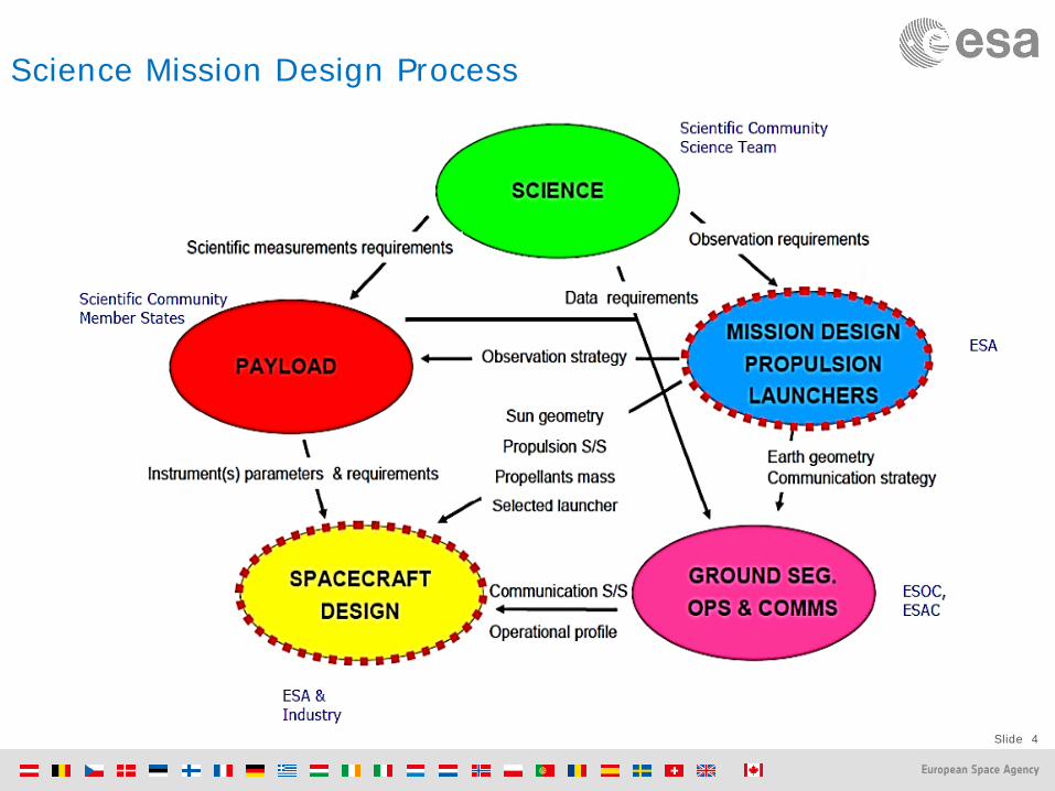
Mission Analysis
Launch Transfer trajectory Insertion into target orbit Orbit and Maintenance End-of-Life disposal

Slide 10
Launchers
Rocket launcher gives initial impulse in order to: Compensate gravity and atmospheric drag Insertion in terrestrial orbit (Low/Medium/Geostationary) Earth Escape Velocity (11km/s, 40000km/h) Insertion into interplanetary transfer orbit 3 types of ESA launchers: Vega (35M€) : 1500kg Low Earth Orbit Soyuz-Fregat (70M€) : 3000kg GEO transfer Ariane 5 (150M€) : 6000-10000kg GEO transfer Mars Express on Soyuz-Fregat
Baikonur 2003

Slide 11
SC size needs to fit the Launcher! Ariane 5
~4.5x10m

Slide 12
Interplanetary Transfer Orbit: Simple Hohmann transfer trajectory
Cheapest transfer ellipse between two circular co-planar orbits:
minimum acceleration: least fuel Other trajectories may
be faster, but more expensive!

Slide 13
Lambert Problem - Cost function
Lambert Problem: In the real world the orbits of the planets are neither coplanar nor circular We are looking for the ellipse or hyperbola which connects r1 to r2 If we specify the time-of-flight(t -t = Dt), only one solution exists Cost function: Minimize fuel consumption for departure and arrival maneuvers (dv1+dv2)
Earth-Mars Transfer : 309 days Launch : 31 Oct 2026 Arrival Date: 6 Sep 2027

Slide 14
Lambert Problem Cost function
Earth-Mercury Transfer : 100 days Launch Date: Date 11 May 2025 Arrival Date: Date 20 Aug 2025
Earth-Venus Transfer : 127 days Launch : Date 1 Jan 2025 Arrival Date: Date 8 May 2025

Slide 15
Hohhman Transfer time durations from Earth
J S
U
P
N

Slide 16
Interplanetary Transfer Orbit: Other trajectories can be much more complex…
L+22.3 years
L+129 days
August 2026
L+1.2 years
L+5.9 years
L+3.5 years
D.S
.M.
D.S
.M.
D.S
.M.
D.S
.M.
...

Slide 17
Gravity Assist concept

Slide 18
B-Plane

Slide 19
Off-plane swing-bys Ulysses Polar orbit

Slide 20
Orbit Insertion
1300kg fuel (TGO) Collission trajectory
Lander release
Insertion trajectory
MARS ORBIT INSERTION

Slide 21
Target orbit selection
MEX motion
Phobosmotion
Drift of orbitLine of apsides
Mars
Crossing of MEX/Phobos orbits
Potential fly-by
MEX motion
Phobosmotion
Drift of orbitLine of apsides
Mars
Crossing of MEX/Phobos orbits
Potential fly-by
Driven by (contradicting) requirements: Resolution, revisit time, link budgets,
ground station visibility, eclipse duration Cost of orbit acquisition and maintenance
(e.g. drag, J-term perturbations, 3rd body perturbations etc…)
Illumination conditions

Slide 22
Space Environment Radiation effects electronics, materials and increase noise in detectors Solar wind & flares: protons: 1 MeV to > 1 GeV Cosmic Rays (protons, heavy nuclei) Spacecraft charging (electric currents) Magnetic Field Solar Radiation Pressure Thermal environment Vacuum: Atomic Oxygen
Radiation belts of Earth, Jupiter,… electrons, protons
Jupiter

Slide 23
Solar Flare caught by SOHO

Slide 24
Spacecraft Sub-systems
Structure Propulsion Orientation Power On-board Computer Communications Thermal Control Payload

Slide 25
Structures
Primary structure (platform harness)
Secondary Structure (equipment + mechanisms)
Structure can be a large fraction of the total satellite mass: ~30 %

Slide 28
MARSIS Antenna deployment 2005

Slide 29
MARSIS Antenna deployment 2005
Slide 30
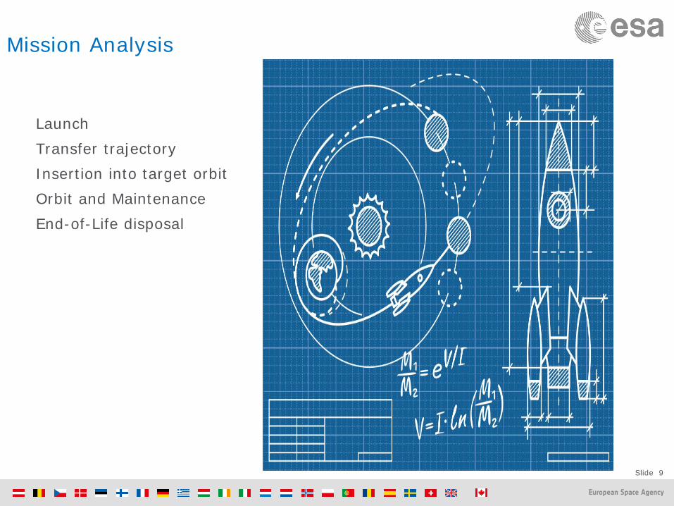
Propulsion
Subsystem in charge of satellite manoeuvring Includes thrusters, tanks, piping and valves Many technologies available
Solid thruster: single one off, high thrust Monopropellant Bi-propellant: Solar Electric
For orbital manoeuvres with high ΔV: “high” Isp (> 300 s), e.g. bipropellant or electric propulsion
For orbital manoeuvres with low ΔV: “medium” Isp and thrust (~1 N) – e.g. monopropellant - hydrazine
For fine control: “low” thrust: (≤10 mN) – cold gas or FEEP based
Specifics for deep space missions: Pressurized tanks will be necessary (engine re-start) Valve isolation and redundancy
500 N engine
22N thruster

Slide 31
Propulsion Example (Mars Express)
Main Engine for Orbit Insertion – 1 x 400 Newtons (for Δv=800m/s)
Thrusters for Attitude Control – 8 x 10 Newtons
Bi-propellant system – 2 tanks 270L: Oxidizer + Propellant – 1 tank 35L : Helium for pressure – 500 kg in total
31

Slide 33
Propulsion Reaction Control System Thrusters
Definition and location of thrusters Thrusting in any direction in any attitude Redundancy required RCS Thrusters could act as backup for main engine
Messenger RCS layout

Slide 34
Future: Solar Sail Force on solar sail 𝐹 = 𝑝 ∙ 𝑐 ∙ 𝐴 ∙ 𝑐𝑐𝑐𝑐 p ~ 4.6 µN / R2 c = 1 ideal absorption ~ 2 ideal reflection
Sail Requirements: Large area Low mass – few µm!
Container + Deployment mechanism (~100 m booms)
Contingency (SAFE mode) recovery strategy needed Limitations for
Communications Attitude control (Large angular inertia – high torque) Solar power generation
JAXA IKAROS mission (2010) 7 µm 14x14m Sail (200m2) 100m/s after 6 months NASA NanoSail-D2 (2010) 4Kg CubeSat (30x10x10 cm): 10m2 sail for de-orbit

Slide 36
GNC Guidance and Navigation Control (AOCS Attitude and Orbit Control System)
Fully redundant system , 3-axis stabilized, Δφ <0.05deg, ω < 0.15 deg/s

Slide 37
Bike wheel video

Slide 38
CD Player: reaction wheels in microgravity

Slide 39
Actuators: Reaction wheels
ExoMars TGO Reaction Wheels: - 4 wheels - 5 Kilograms each wheel - 23Nms Angular Momentum - 7,500 RPM Spin speed: - 35x12cm centimeters
Lunar Reconnaisance Orbiter
Mars Express

Slide 40
Inertial Sensors: Star Trackers
Rosetta Star Tracker 6 July 2015

Slide 41
Inertial Sensors: Star Tracker Examples
Mars Express ExoMars TGO

Slide 42
Star Tracker Rosetta Anomaly 2015
Rosetta Star Tracker Anomaly July 2015

Slide 44
Electrical Power Subsystem (EPS)
How Much Power Does a Spacecraft Need? Small (Light-Bulb Sized)
Mars Climate Orbiter; Mars Odyssey: 300W Mars Polar Lander; Mars Exploration Rover: 150W Stardust; Genesis: 200W
Medium (Hair Dryer Sized) Mars Reconnaissance Orbiter (1kW) Metereological Satellites (2kW - 5kW) Commercial & Military Communication Satellites (1kW -
15kW)
Large (House-Sized) Hubble Space Telescope (25kW) NASA / International Space Station (50kW)
Monster (City-Sized) Lunar & Martian Stations (100kW - 1MW)

Slide 45
Electrical Power Subsystem (EPS)
Solar Panels Panels need to point to the sun Need special design or rotation mechanism Solar Flux at Earth ~1400 W/m2, at Mars ~600W/m2 MEX: 11.4m2 sillicon cells ~10% eff. => ~500 Watts
(new technologies increase efficiency ~30%)
Battery Needed for eclipses, emergency, … MEX: Lithium-Ion battery 67 Amp hour
(60 times a normal phone battery) Alternative Power sources
Nuclear Power (RTG, RHU’s, ASGR’s), constant power (necessary for missions beyond Jupiter)
Provides electrical power to S/C and payload
Slide 46
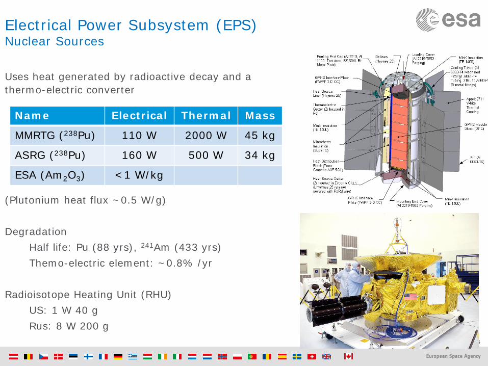
Electrical Power Subsystem (EPS) Nuclear Sources
Uses heat generated by radioactive decay and a thermo-electric converter (Plutonium heat flux ~0.5 W/g) Degradation
Half life: Pu (88 yrs), 241Am (433 yrs) Themo-electric element: ~0.8% /yr
Radioisotope Heating Unit (RHU)
US: 1 W 40 g Rus: 8 W 200 g
Name Electrical Thermal Mass
MMRTG (238Pu) 110 W 2000 W 45 kg
ASRG (238Pu) 160 W 500 W 34 kg
ESA (Am2O3) <1 W/kg

Slide 47
Communications
Earth-Spacecraft-Lander transmission Science Data, Commands, housekeeping, Tracking (location, velocity), Radio science
Radio Link Data rate increases with antenna size and frequency, Data rate decreases with distance (MEX maximum 228kbps X-band)
At short distance low frequency is enough: S band (2 GHz), UHF (<1GHz) for lander
At longer distance higher frequency needed: X (or Ka)-band (7/32 GHz)
Spacecraft Antenna MEX High Gain Antenna 1.6m diameter X/S-band MEX Low Gain Antenna (emergency) 20cm S-band + UHF for lander
Ground Stations ESA 35m diameter: Madrid, Australia, Argentina NASA 35/70m diameter: Madrid, Australia, USA

Slide 49
HGA Performance
High Gain Antenna (HGA) versus pointing performance Optimum antenna diameter for known AOCS off-pointing Further iteration to be done once AOCS performance is known
Diam1
Diam2 > Diam1Pointin
P
1
2
3
4
(the
Diam1
Diam2 > Diam1Pointin
P
11
22
33
44
(the
Parabolic reflector antenna @ 32,05GHz
0,00
0,05
0,10
0,15
0,20
0,25
0,30
0,35
2 2,2 2,4 2,6 2,8 3 4 5 6
Antenna diameter [m]
Dou
ble
side
d be
amw
idth
[deg
]
51,50
52,00
52,50
53,00
53,50
54,00
54,50
55,00
55,50
56,00
Gai
n w
ith o
ff-po
intin
g [d
Bi]
3dB double sided beamwidth [deg] Gain with off-pointing of 0,1deg [dBi]see also in SMAD

Slide 50
Thermal Control Subsystem
The subsystem that allows keeping the spacecraft and payload temperatures within allowable limits
Generally, separated thermal control for spacecraft
and payload due to different temperature requirements
Basic principles:
Insulate the spacecraft from the environment to keep stable temperatures inside and provide an aperture for dissipation of excess heat (radiator).
During eclipse provide heating power to keep the spacecraft warm
• thermal blankets (MLI) • external paints to modify
optical properties • radiator(s), associated
heat transport devices (heat pipes, high conductivity paths)

Slide 51
Heat sources
Thermal Control
External Temperatures -100 ~ +150oC Multi-Layer Insulator to avoid
illumination and dissipation Most electrical power is
converted into heat Radiators + Heaters + pipes…
~10º
Sun Planets
Electronics Heaters
Rosetta radiator louvers
Dissipation Sources
Antenna, Radar
Heat Leaks (openings)
Radiators (& louvers)

Slide 54
On Board Data Handling (OBDH)
Data Management System Telecommand distribution Telemetry data Events, housekeeping, … Control and Data Managament Units 4 Processor Modules (2 DMS + 2 AOCS) Bus Architecture + High speed Link Solid State Mass Memory Payload Data Handling Unit (MEX: 8 Gbit EXM: 1024Gbit)

Slide 55
Payload Subsystems

Slide 57
System Summary
Mission profile & lifetime Launcher: launch mass, fairing Budgets: Mass, Power Total system margin
Equipment 5~20% (based on TRL) Total System Level 20%
Operations, Cost, risks, schedule

Slide 58
Technology Readiness Levels (TRL)

Slide 60
Operations

Slide 61
Cost
Cost estimate is very difficult ! 3 basic methods: Bottom up approach, parametric analysis or by analogy with other missions Need cost model and data base with cost info Most difficult is the estimate on engineering, validation & verification cost, manpower etc. extra cost of technology TRL upgrade! Cost is driven by complexity of mission
Mission CaC: Cost at Completion comprises: Development cost Procurement cost of the space segment (industrial cost) Test facilities cost Launch cost Mission operation cost Science operations cost (science planning, data processing and archiving) Agency cost and margins Management costs Payload cost Contingency …

Slide 62
Cosmic Vision Science Program Missions
L-missions (L1 JUICE , L2 ATHENA, L3 Gravitational Waves Observatory)
Cost to ESA of around 2 annual budgets (1000 M€)
European led flagships with <20% international contributions
May need technology development
M-missions (M1 Solar Orbiter, M2 Euclid, M3 Plato, M4 ARIEL/THOR/XIPE?, …)
Cost to ESA of around one annual budget (500 M€)
ESA led or contribution to international collaboration.
No technology development
S-missions (S1 CHEOPS, S2 SMILE, ...)
Cost to ESA of 0.1 annual budgets (50 M€)
National agencies play a leading role
No technology development
O-missions Missions of opportunity, led by other agencies, small contributions.

¿preguntas?
GRACIAS