EPFL B. Varga - IETF Datatracker
238
DetNet N. Finn Internet-Draft Huawei Technologies Co. Ltd Intended status: Standards Track J-Y. Le Boudec Expires: January 3, 2019 E. Mohammadpour EPFL B. Varga J. Farkas Ericsson July 2, 2018 DetNet Bounded Latency draft-finn-detnet-bounded-latency-01 Abstract This document presents a parameterized timing model for Deterministic Networking so that existing and future standards can achieve bounded latency and zero congestion loss. Status of This Memo This Internet-Draft is submitted in full conformance with the provisions of BCP 78 and BCP 79. Internet-Drafts are working documents of the Internet Engineering Task Force (IETF). Note that other groups may also distribute working documents as Internet-Drafts. The list of current Internet- Drafts is at https://datatracker.ietf.org/drafts/current/. Internet-Drafts are draft documents valid for a maximum of six months and may be updated, replaced, or obsoleted by other documents at any time. It is inappropriate to use Internet-Drafts as reference material or to cite them other than as "work in progress." This Internet-Draft will expire on January 3, 2019. Copyright Notice Copyright (c) 2018 IETF Trust and the persons identified as the document authors. All rights reserved. This document is subject to BCP 78 and the IETF Trust’s Legal Provisions Relating to IETF Documents (https://trustee.ietf.org/license-info) in effect on the date of publication of this document. Please review these documents carefully, as they describe your rights and restrictions with respect to this document. Code Components extracted from this document must Finn, et al. Expires January 3, 2019 [Page 1]
Transcript of EPFL B. Varga - IETF Datatracker

DetNet N. FinnInternet-Draft Huawei Technologies Co. LtdIntended status: Standards Track J-Y. Le BoudecExpires: January 3, 2019 E. Mohammadpour EPFL B. Varga J. Farkas Ericsson July 2, 2018
DetNet Bounded Latency draft-finn-detnet-bounded-latency-01
Abstract
This document presents a parameterized timing model for Deterministic Networking so that existing and future standards can achieve bounded latency and zero congestion loss.
Status of This Memo
This Internet-Draft is submitted in full conformance with the provisions of BCP 78 and BCP 79.
Internet-Drafts are working documents of the Internet Engineering Task Force (IETF). Note that other groups may also distribute working documents as Internet-Drafts. The list of current Internet- Drafts is at https://datatracker.ietf.org/drafts/current/.
Internet-Drafts are draft documents valid for a maximum of six months and may be updated, replaced, or obsoleted by other documents at any time. It is inappropriate to use Internet-Drafts as reference material or to cite them other than as "work in progress."
This Internet-Draft will expire on January 3, 2019.
Copyright Notice
Copyright (c) 2018 IETF Trust and the persons identified as the document authors. All rights reserved.
This document is subject to BCP 78 and the IETF Trust’s Legal Provisions Relating to IETF Documents (https://trustee.ietf.org/license-info) in effect on the date of publication of this document. Please review these documents carefully, as they describe your rights and restrictions with respect to this document. Code Components extracted from this document must
Finn, et al. Expires January 3, 2019 [Page 1]

Internet-Draft DetNet Bounded Latency July 2018
include Simplified BSD License text as described in Section 4.e of the Trust Legal Provisions and are provided without warranty as described in the Simplified BSD License.
Table of Contents
1. Introduction . . . . . . . . . . . . . . . . . . . . . . . . 2 2. Conventions Used in This Document . . . . . . . . . . . . . . 3 3. Terminology and Definitions . . . . . . . . . . . . . . . . . 4 4. DetNet bounded latency model . . . . . . . . . . . . . . . . 4 4.1. Flow creation . . . . . . . . . . . . . . . . . . . . . . 4 4.2. End-to-end model . . . . . . . . . . . . . . . . . . . . 5 4.3. Relay system model . . . . . . . . . . . . . . . . . . . 5 5. Computing End-to-end Latency Bounds . . . . . . . . . . . . . 7 5.1. Examples of Computations . . . . . . . . . . . . . . . . 8 5.1.1. Per-flow queuing . . . . . . . . . . . . . . . . . . 8 5.1.2. Time-Sensitive Networking with Asynchronous Traffic Shaping . . . . . . . . . . . . . . . . . . . . . . . 8 6. Achieving zero congestion loss . . . . . . . . . . . . . . . 9 6.1. A General Formula . . . . . . . . . . . . . . . . . . . . 9 7. Queuing model . . . . . . . . . . . . . . . . . . . . . . . . 10 7.1. Queuing data model . . . . . . . . . . . . . . . . . . . 10 7.2. IEEE 802.1 Queuing Model . . . . . . . . . . . . . . . . 12 7.2.1. Queuing Data Model with Preemption . . . . . . . . . 12 7.2.2. Transmission Selection Model . . . . . . . . . . . . 13 7.3. Time-Sensitive Networking with Asynchronous Traffic Shaping . . . . . . . . . . . . . . . . . . . . . . . . . 15 7.4. Other queuing models, e.g. IntServ . . . . . . . . . . . 17 8. Parameters for the bounded latency model . . . . . . . . . . 17 8.1. Sender parameters . . . . . . . . . . . . . . . . . . . . 17 8.2. Relay system parameters . . . . . . . . . . . . . . . . . 17 9. References . . . . . . . . . . . . . . . . . . . . . . . . . 17 9.1. Normative References . . . . . . . . . . . . . . . . . . 17 9.2. Informative References . . . . . . . . . . . . . . . . . 18 Authors’ Addresses . . . . . . . . . . . . . . . . . . . . . . . 20
1. Introduction
The ability for IETF Deterministic Networking (DetNet) or IEEE 802.1 Time-Sensitive Networking (TSN) to provide the DetNet services of bounded latency and zero congestion loss depends upon A) configuring and allocating network resources for the exclusive use of DetNet/TSN flows; B) identifying, in the data plane, the resources to be utilized by any given packet, and C) the detailed behavior of those resources, especially transmission queue selection, so that latency bounds can be reliably assured. Thus, DetNet is an example of an INTSERV Guaranteed Quality of Service [RFC2212]
Finn, et al. Expires January 3, 2019 [Page 2]

Internet-Draft DetNet Bounded Latency July 2018
As explained in [I-D.ietf-detnet-architecture], DetNet flows are characterized by 1) a maximum bandwidth, guaranteed either by the transmitter or by strict input metering; and 2) a requirement for a guaranteed worst-case end-to-end latency. That latency guarantee, in turn, provides the opportunity for the network to supply enough buffer space to guarantee zero congestion loss. To be of use to the applications identified in [I-D.ietf-detnet-use-cases], it must be possible to calculate, before the transmission of a DetNet flow commences, both the worst-case end-to-end network latency, and the amount of buffer space required at each hop to ensure against congestion loss.
Rather than defining, in great detail, specific mechanisms to be used to control packet transmission at each output port, this document presents a timing model for sources, destinations, and the network nodes that relay packets. The parameters specified in this model:
o Characterize a DetNet flow in a way that provides externally measureable verification that the sender is conforming to its promised maximum, can be implemented reasonably easily by a sending device, and does not require excessive over-allocation of resources by the network.
o Enable resonably accurate computation of worst-case end-to-end latency, in a way that requires as little detailed knowledge as possible of the behavior of the Quality of Service (QoS) algorithms implemented in each devince, including queuing, shaping, metering, policing, and transmission selection techniques.
Using the model presented in this document, it should be possible for an implementor, user, or standards development organization to select a particular set of QoS algorithms for each device in a DetNet network, and to select a resource reservation algorithm for that network, so that those elements can work together to provide the DetNet service.
This document does not specify any resource reservation protocol or server. It does not describe all of the requirements for that protocol or server. It does describe a set of requirements for resource reservation algorithms and for QoS algorithms that, if met, will enable them to work together.
2. Conventions Used in This Document
The key words "MUST", "MUST NOT", "REQUIRED", "SHALL", "SHALL NOT", "SHOULD", "SHOULD NOT", "RECOMMENDED", "MAY", and "OPTIONAL" in this document are to be interpreted as described in [RFC2119].
Finn, et al. Expires January 3, 2019 [Page 3]

Internet-Draft DetNet Bounded Latency July 2018
The lowercase forms with an initial capital "Must", "Must Not", "Shall", "Shall Not", "Should", "Should Not", "May", and "Optional" in this document are to be interpreted in the sense defined in [RFC2119], but are used where the normative behavior is defined in documents published by SDOs other than the IETF.
3. Terminology and Definitions
This document uses the terms defined in [I-D.ietf-detnet-architecture].
4. DetNet bounded latency model
4.1. Flow creation
The bounded latency model assusmes the use of the following paradigm for provisioning a particular DetNet flow:
1. Perform any onfiguration required by the relay systems in the network for the classes of service to be offered, including one or more classes of DetNet service. This configuration is general; it is not tied to any particular flow.
2. Characterize the DetNet flow in terms of limitations on the sender Section 8.1 and flow requirements Section 8.2.
3. Establish the path that the DetNet flow will take through the network from the source to the destination(s). This can be a point-to-point or a point-to-multipoint path.
4. Select one of the DetNet classes of service for the DetNet flow.
5. Compute the worst-case end-to-end latency for the DetNet flow. In the process, determine whether sufficient resources are available for that flow to guarantee the required latency and provide zero congestion loss.
6. Assuming that the resources are available, commit those resources to the flow. This may or may not require adjusting the parameters that control the QoS algorithms at each hop along the flow’s path.
This paradigm can be static and/or dynamic, and can be implemented using peer-to-peer protocols or with a central server model. In some situations, backtracking and recursing through this list may be necessary.
Finn, et al. Expires January 3, 2019 [Page 4]

Internet-Draft DetNet Bounded Latency July 2018
Issues such as un-provisioning a DetNet flow in favor of another when resources are scarce are not considered. How the path to be taken by a DetNet flow is chosen is not considered in this document.
4.2. End-to-end model
[Suggestion: This is the introduction to network calculus. The starting point is a model in which a relay system is a black box.]
4.3. Relay system model
[NWF I think that at least some of this will be useful. We won’t know until we see what J-Y has to say in Section 4.2. I’m especially interested in whether J-Y thinks that the "output delay" in Figure 1 is useful in determining the number of buffers needed in the next hop. It is possible that we can define the parameters we need without this section.]
In Figure 1 we see a breakdown of the per-hop latency experienced by a packet passing through a relay system, in terms that are suitable for computing both hop-by-hop latency and per-hop buffer requirements.
DetNet relay node A DetNet relay node B +-------------------+ +-------------------+ | Reg. Queue | | Reg. Queue | | +-+-+ +-+-+-+ | | +-+-+ +-+-+-+ | -->+ | | | | | | + +------->+ | | | | | | + +---> | +-+-+ +-+-+-+ | | +-+-+ +-+-+-+ | | | | | +-------------------+ +-------------------+ |<->|<-->|<---->|<->|<------>|<->|<-->|<---->|<->|<-- 2,3 4 5 6 1 2,3 4 5 6 1 2,3 1: Output delay 3: Preemption delay 2: Link delay 4: Processing delay 5: Regulation delay 6: Queuing delay.
Figure 1: Timing model for DetNet or TSN
In Figure 1, we see two DetNet relay nodes (typically, bridges or routers), with a wired link between them. In this model, the only queues we deal with explicitly are attached to the output port; other queues are modeled as variations in the other delay times. (E.g., an input queue could be modeled as either a variation in the link delay [2] or the processing delay [4].) There are five delays that a packet can experience from hop to hop.
1. Output delay
Finn, et al. Expires January 3, 2019 [Page 5]

Internet-Draft DetNet Bounded Latency July 2018
The time taken from the selection of a packet for output from a queue to the transmission of the first bit of the packet on the physical link. If the queue is directly attached to the physical port, output delay can be a constant. But, in many implementations, the queuing mechanism in a forwarding ASIC is separated from a multi-port MAC/PHY, in a second ASIC, by a multiplexed connection. This causes variations in the output delay that are hard for the forwarding node to predict or control.
2. Link delay The time taken from the transmission of the first bit of the packet to the reception of the last bit, assuming that the transmission is not suspended by a preemption event. This delay has two components, the first-bit-out to first-bit-in delay and the first-bit-in to last-bit-in delay that varies with packet size. The former is typically measured by the Precision Time Protocol and is constant (see [I-D.ietf-detnet-architecture]). However, a virtual "link" could exhibit a variable link delay.
3. Preemption delay If the packet is interrupted (e.g. [IEEE8023br] preemption) in order to transmit another packet or packets, an arbitrary delay can result.
4. Processing delay This delay covers the time from the reception of the last bit of the packet to that packet being eligible, if there were no other packets in the queue, for selection for output. This delay can be variable, and depends on the details of the operation of the forwarding node.
5. Regulation delay This is the time spent from the insertion of the packet into a regulation queue until the time the packet is declared eligible according to its regulation constraints. We assume that this time can be calculated based on the details of regulation policy. If there is no regulation, this time is zero.
6. Queuing delay This is the time spent for a packet from being declared eligibile until being selected for output on the next link. We assume that this time is calculable based on the details of the queuing mechanism. If there is no regulation, this time is from the insertion of the packet into a queue until it is selected for output on the next link.
Not shown in Figure 1 are the other output queues that we presume are also attached to that same output port as the queue shown, and
Finn, et al. Expires January 3, 2019 [Page 6]

Internet-Draft DetNet Bounded Latency July 2018
against which this shown queue competes for transmission opportunities.
The initial and final measurement point in this analysis (that is, the definition of a "hop") is the point at which a packet is selected for output. In general, any queue selection method that is suitable for use in a DetNet network includes a detailed specification as to exactly when packets are selected for transmission. Any variations in any of the delay times 1-4 result in a need for additional buffers in the queue. If all delays 1-4 are constant, then any variation in the time at which packets are inserted into a queue depends entirely on the timing of packet selection in the previous node. If the delays 1-4 are not constant, then additional buffers are required in the queue to absorb these variations. Thus:
o Variations in output delay (1) require buffers to absorb that variation in the next hop, so the output delay variations of the previous hop (on each input port) must be known in order to calculate the buffer space required on this hop.
o Variations in processing delay (4) require additional output buffers in the queues of that same Detnet relay node. Depending on the details of the queueing delay (6) calculations, these variations need not be visible outside the DetNet relay node.
5. Computing End-to-end Latency Bounds
End-to-end latency bounds can be computed using the delay model in Section 4.3. Here it is important to be aware that for several queuing mechanisms, the worst-case end-to-end delay is less than the sum of the per-hop worst-case delays. An end-to-end latency bound for one detnet flow can be computed as
end_to_end_latency_bound = non_queuing_latency + queuing_latency
The two terms in the above formula are computed as follows. First, at the h-th hop along the path of this detnet flow, obtain an upper bound per-hop_non_queuing_latency[h] on the sum of delays 1,2,3,4 of Figure 1. These upper-bounds are expected to depend on the specific technology of the node at the h-th hop but not on the T-SPEC of this detnet flow. Then set non_queuing_latency = the sum of per- hop_non_queuing_latency[h] over all hops h.
Second, compute queuing_latency as an upper bound to the sum of the queuing delays along the path. The value of queuing_latency depends on the T-SPEC of this flow and possibly of other flows in the network, as well as the specifics of the queuing mechanisms deployed along the path of this flow.
Finn, et al. Expires January 3, 2019 [Page 7]

Internet-Draft DetNet Bounded Latency July 2018
For several queuing mechanisms, queuing_latency is less than the sum of upper bounds on the queuing delays (5,6) at every hop. Section 5.1 gives such practical computation examples.
For other queuing mechanisms the only available value of queuing_latency is the sum of the per-hop queuing delay bounds. In such cases, the computation of per-hop queuing delay bounds must account for the fact that the T-SPEC of a detnet flow is no longer satisfied at the ingress of a hop, since burstiness increases as one flow traverses one detnet node.
5.1. Examples of Computations
5.1.1. Per-flow queuing
[[ JYLB: THIS IS WHERE DETAILS OF END-TO-END LATENCY COMPUTATION ARE GIVEN FOR PER-FLOW QUEUING]]
5.1.2. Time-Sensitive Networking with Asynchronous Traffic Shaping
Figure 2 shows an example of a network with 5 nodes, which have the queuing model as Section 7.3. An end-to-end delay bound for flow f of a given AVB class (A or B), traversing from node 1 to 5, is calculated as following:
end_to_end_latency_bound_of_flow_f = C12 + C23 + C34 + S4
In the above formula, Cij is a bound on the aggregate response time of the AVB FIFO queue with CBS (Credit Based Shaper) in node i and interleaved regulator of node j, and S4 is a bound on the response time of the AVB FIFO queue with CBS in node 4 for flow f. In fact, using the delay definitions in Section 4.3, Cij is a bound on sum of the delays 1,2,3,6 of node i and 4,5 of node j. Similarly, S4 is a bound on sum of the delays 1,2,3,6 of node 4. The detail of calculation for the these response time bounds can be found in [TSNwithATS].
f -----------------------------> +---+ +---+ +---+ +---+ +---+ | 1 |---| 2 |---| 3 |---| 4 |---| 5 | +---+ +---+ +---+ +---+ +---+ \__C12_/\__C23_/\__C34_/\_S4_/
Figure 2: End-to-end latency computation example
Finn, et al. Expires January 3, 2019 [Page 8]
Internet-Draft DetNet Bounded Latency July 2018
REMARK: The end-to-end delay bound calculation provided here gives a much better upper bound in comparison with end-to-end delay bound computation by adding the delay bounds of each node in the path of a flow [TSNwithATS].
6. Achieving zero congestion loss
When the input rate to an output queue exceeds the output rate for a sufficient length of time, the queue must overflow. This is congestion loss, and this is what deterministic networking seeks to avoid.
6.1. A General Formula
To avoid congestion losses, an upper bound on the backlog present in the queue of Figure 1 must be computed during path computation. This bound depends on the set of flows that use this queue, the details of the specific queuing mechanism and an upper bound on the processing delay (4). The queue must contain the packet in transmission plus all other packets that are waiting to be selected for output.
A conservative backlog bound, that applies to all systems, can be derived as follows.
The backlog bound is counted in data units (bytes, or words of multiple bytes) that are relevant for buffer allocation. For every class we need one buffer space for the packet in transmission, plus space for the packets that are waiting to be selected for output. Excluding transmission and preemption times, the packets are waiting in the queue since reception of the last bit, for a duration equal to the processing delay (4) plus the queuing delays (5,6).
Let
o nb_classes be the number of classes of traffic that may use this output port
o total_in_rate be the sum of the line rates of all input ports that send traffic of any class to this output port. The value of total_in_rate is in data units (e.g. bytes) per second.
o nb_input_ports be the number input ports that send traffic of any class to this output port
o max_packet_length be the maximum packet size for packets of any class that may be sent to this output port. This is counted in data units.
Finn, et al. Expires January 3, 2019 [Page 9]

Internet-Draft DetNet Bounded Latency July 2018
o max_delay45 be an upper bound, in seconds, on the sum of the processing delay (4) and the queuing delays (5,6) for a packet of any class at this ouput port.
Then a bound on the backlog of traffic of all classes in the queue at this output port is
backlog_bound = ( nb_classes + nb_input_ports ) * max_packet_length + total_in_rate* max_delay45
7. Queuing model
[[ JYLB: THIS IS WHERE DETAILS OF END-TO-END LATENCY COMPUTATION ARE GIVEN FOR PER-FLOW QUEUING AND FOR TSN WITH ATS]]
7.1. Queuing data model
Sophisticated QoS mechanisms are available in Layer 3 (L3), see, e.g., [RFC7806] for an overview. In general, we assume that "Layer 3" queues, shapers, meters, etc., are instantiated hierarchically above the "Layer 2" queuing mechanisms, among which packets compete for opportunities to be transmitted on a physical (or sometimes, logical) medium. These "Layer 2 queuing mechanisms" are not the province solely of bridges; they are an essential part of any DetNet relay node. As illustrated by numerous implementation examples, the "Layer 3" some of mechanisms described in documents such as [RFC7806] are often integrated, in an implementation, with the "Layer 2" mechanisms also implemented in the same system. An integrated model is needed in order to successfully predict the interactions among the different queuing mechanisms needed in a network carrying both DetNet flows and non-DetNet flows.
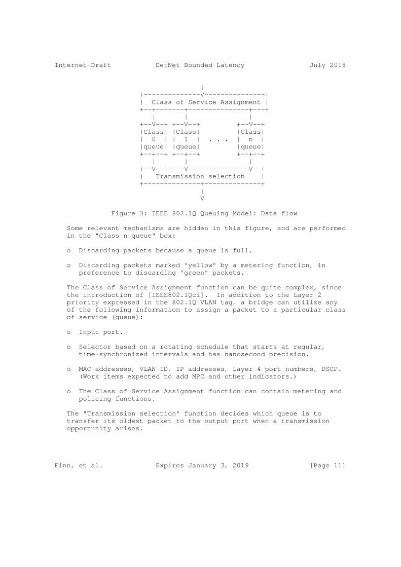
Figure 3 shows the (very simple) model for the flow of packets through the queues of an IEEE 802.1Q bridge. Packets are assigned to a class of service. The classes of service are mapped to some number of physical FIFO queues. IEEE 802.1Q allows a maximum of 8 classes of service, but it is more common to implement 2 or 4 queues on most ports.
Finn, et al. Expires January 3, 2019 [Page 10]
Internet-Draft DetNet Bounded Latency July 2018
| +--------------V---------------+ | Class of Service Assignment | +--+-------+---------------+---+ | | | +--V--+ +--V--+ +--V--+ |Class| |Class| |Class| | 0 | | 1 | . . . | n | |queue| |queue| |queue| +--+--+ +--+--+ +--+--+ | | | +--V-------V---------------V--+ | Transmission selection | +--------------+--------------+ | V
Figure 3: IEEE 802.1Q Queuing Model: Data flow
Some relevant mechanisms are hidden in this figure, and are performed in the "Class n queue" box:
o Discarding packets because a queue is full.
o Discarding packets marked "yellow" by a metering function, in preference to discarding "green" packets.
The Class of Service Assignment function can be quite complex, since the introduction of [IEEE802.1Qci]. In addition to the Layer 2 priority expressed in the 802.1Q VLAN tag, a bridge can utilize any of the following information to assign a packet to a particular class of service (queue):
o Input port.
o Selector based on a rotating schedule that starts at regular, time-synchronized intervals and has nanosecond precision.
o MAC addresses, VLAN ID, IP addresses, Layer 4 port numbers, DSCP. (Work items expected to add MPC and other indicators.)
o The Class of Service Assignment function can contain metering and policing functions.
The "Transmission selection" function decides which queue is to transfer its oldest packet to the output port when a transmission opportunity arises.
Finn, et al. Expires January 3, 2019 [Page 11]

Internet-Draft DetNet Bounded Latency July 2018
7.2. IEEE 802.1 Queuing Model
7.2.1. Queuing Data Model with Preemption
Figure 3 must be modified if the output port supports preemption ([IEEE8021Qbu] and [IEEE8023br]). This modification is shown in Figure 4.
| +------------------------------V------------------------------+ | Class of Service Assignment | +--+-------+-------+-------+-------+-------+-------+-------+--+ | | | | | | | | +--V--+ +--V--+ +--V--+ +--V--+ +--V--+ +--V--+ +--V--+ +--V--+ |Class| |Class| |Class| |Class| |Class| |Class| |Class| |Class| | a | | b | | c | | d | | e | | f | | g | | h | |queue| |queue| |queue| |queue| |queue| |queue| |queue| |queue| +--+--+ +--+--+ +--+--+ +--+--+ +--+--+ +--+--+ +--+--+ +--+--+ | | | +-+ | | | | | | | | | | | | +--V-------V-------V------+ +V-----V-------V-------V-------V--+ | Interrupted xmit select | | Preempting xmit select | 802.1 +-------------+-----------+ +----------------+----------------+ | | ====== +-------------V-----------+ +----------------V----------------+ | Preemptible MAC | | Express MAC | 802.3 +--------+----------------+ +----------------+----------------+ | | +--------V-----------------------------------V----------------+ | MAC merge sublayer | +--------------------------+----------------------------------+ | +--------------------------V----------------------------------+ | PHY (unaware of preemption) | +--------------------------+----------------------------------+ | V
Figure 4: IEEE 802.1Q Queuing Model: Data flow with preemption
From Figure 4, we can see that, in the IEEE 802 model, the preemption feature is modeled as consisting of two MAC/PHY stacks, one for packets that can be interrupted, and one for packets that can interrupt the interruptible packets. The Class of Service (queue) determines which packets are which. In Figure 4, the classes of service are marked "a, b, ..." instead of with numbers, in order to avoid any implication about which numeric Layer 2 priority values correspond to preemptible or preempting queues. Although it shows
Finn, et al. Expires January 3, 2019 [Page 12]

Internet-Draft DetNet Bounded Latency July 2018
three queues going to the preemptible MAC/PHY, any assignment is possible.
7.2.2. Transmission Selection Model
In Figure 5, we expand the "Transmission selection" function of Figure 4.
Figure 5 does NOT show the data path. It shows an example of a configuration of the IEEE 802.1Q transmission selection box shown in Figure 3 and Figure 4. Each queue m presents a "Class m Ready" signal. These signals go through various logic, filters, and state machines, until a single queue’s "not empty" signal is chosen for presentation to the underlying MAC/PHY. When the MAC/PHY is ready to take another output packet, then a packet is selected from the one queue (if any) whose signal manages to pass all the way through the transmission selection function.
Finn, et al. Expires January 3, 2019 [Page 13]

Internet-Draft DetNet Bounded Latency July 2018
+-----+ +-----+ +-----+ +-----+ +-----+ +-----+ +-----+ +-----+ |Class| |Class| |Class| |Class| |Class| |Class| |Class| |Class| | 1 | | 0 | | 4 | | 5 | | 6 | | 7 | | 2 | | 3 | |Ready| |Ready| |Ready| |Ready| |Ready| |Ready| |Ready| |Ready| +--+--+ +--+--+ +--+--+ +-XXX-+ +--+--+ +--+--+ +--+--+ +--+--+ | | | | | | | | +--V--+ +--V--+ +--+--+ +--V--+ | +--V--+ +--V--+ | |Prio.| |Prio.| |Prio.| |Prio.| | |Sha- | |Sha- | | | 0 | | 4 | | 5 | | 6 | | | per| | per| | | PFC | | PFC | | PFC | | PFC | | | A | | B | | +--+--+ +--+--+ +-XXX-+ +-XXX-+ | +--+--+ +-XXX-+ | | | | | +--V--+ +--V--+ +--V--+ +--+--+ +--+--+ +--V--+ +--V--+ +--+--+ |Time | |Time | |Time | |Time | |Time | |Time | |Time | |Time | | Gate| | Gate| | Gate| | Gate| | Gate| | Gate| | Gate| | Gate| | 1 | | 0 | | 4 | | 5 | | 6 | | 7 | | 2 | | 3 | +--+--+ +-XXX-+ +--+--+ +--+--+ +-XXX-+ +--+--+ +-XXX-+ +--+--+ | | | +--V-------+-------V-------+--+ | |802.1Q Enhanced Transmission | | | Selection (ETS) = Weighted | | | Fair Queuing (WFQ) | | +--+-------+------XXX------+--+ | | | +--V-------+-------+-------+-------+-------V-------+-------+--+ | Strict Priority selection (rightmost first) | +-XXX------+-------+-------+-------+-------+-------+-------+--+ | V
Figure 5: 802.1Q Transmission Selection
The following explanatory notes apply to Figure 5
o The numbers in the "Class n Ready" boxes are the values of the Layer 2 priority that are assigned to that Class of Service in this example. The rightmost CoS is the most important, the leftmost the least. Classes 2 and 3 are made the most important, because they carry DetNet flows. It is all right to make them more important than the priority 7 queue, which typically carries critical network control protocols such as spanning tree or IS-IS, because the shaper ensures that the highest priority best-effort queue (7) will get reasonable access to the MAC/PHY. Note that Class 5 has no Ready signal, indicating that that queue is empty.
o Below the Class Ready signals are shown the Priority Flow Control gates (IEEE Std 802.1Qbb-2011 Priority-based Flow Control, now [IEEE8021Q] clause 36) on Classes of Service 1, 0, 4, and 5, and
Finn, et al. Expires January 3, 2019 [Page 14]

Internet-Draft DetNet Bounded Latency July 2018
two 802.1Q shapers, A and B. Perhaps shaper A conforms to the IEEE Std 802.1Qav-2009 (now [IEEE8021Q] clause 34) credit-based shaper, and shaper B conforms to [IEEE8021Qcr] Asynchronous Traffic Shaper. Any given Class of Service can have either a PFC function or a shaper, but not both.
o Next are the IEEE Std 802.1Qbv time gates ([IEEE8021Qbv]). Each one of the 8 Classes of Service has a time gate. The gates are controlled by a repeating schedule that restarts periodically, and can be programmed to turn any combination of gates on or off with nanosecond precision. (Although the implementation is not necessarily that accurate.)
o Following the time gates, any number of Classes of Service can be linked to one ore more instances of the Enhanced Transmission Selection function. This does weighted fair queuing among the members of its group.
o A final selection of the one queue to be selected for output is made by strict priority. Note that the priority is determined not by the Layer 2 priority, but by the Class of Service.
o An "XXX" in the lower margin of a box (e.g. "Prio. 5 PFC" indicates that the box has blocked the "Class n Ready" signal.
o IEEE 802.1Qch Cyclic Queuing and Forwarding [IEEE802.1Qch] is accomplished using two or three queues (e.g. 2 and 3 in the figure), using sophisticated time-based schedules in the Class of Service Assignment function, and using the IEEE 802.1Qbv time gates [IEEE8021Qbv] to swap between the output buffers.
7.3. Time-Sensitive Networking with Asynchronous Traffic Shaping
Consider a network with a set of nodes (switches and hosts) along with a set of flows between hosts. Hosts are sources or destinations of flows. There are four types of flows, namely, control-data traffic (CDT), class A, class B, and best effort (BE) in decreasing order of priority. Flows of classes A and B are together referred to as AVB flows. It is assumed a subset of TSN functions as described next.
It is also assumed that contention occurs only at the output port of a TSN node. Each node output port performs per-class scheduling with eight classes: one for CDT, one for class A traffic, one for class B traffic, and five for BE traffic denoted as BE0-BE4 (according to TSN standard). In addition, each node output port also performs per-flow regulation for AVB flows using an interleaved regulator (IR), called Asynchronous Traffic Shaper (ATS) in TSN. Thus, at each output port
Finn, et al. Expires January 3, 2019 [Page 15]

Internet-Draft DetNet Bounded Latency July 2018
of a node, there is one interleaved regulator per-input port and per- class. The detailed picture of scheduling and regulation architecture at a node output port is given by Figure 6. The packets received at a node input port for a given class are enqueued in the respective interleaved regulator at the output port. Then, the packets from all the flows, including CDT and BE flows, are enqueued in a class based FIFO system (CBFS) [TSNwithATS].
+--+ +--+ +--+ +--+ | | | | | | | | |IR| |IR| |IR| |IR| | | | | | | | | +-++XXX++-+ +-++XXX++-+ | | | | | | | | +-----+ +-v-XXX-v-+ +-v-XXX-v-+ +-----+ +-----+ +-----+ +-----+ +-----+ | | | | | | |Class| |Class| |Class| |Class| |Class| | CDT | | Class A | | Class B | | BE4 | | BE3 | | BE2 | | BE1 | | BE0 | | | | | | | | | | | | | | | | | +--+--+ +----+----+ +----+----+ +--+--+ +--+--+ +--+--+ +--+--+ +--+--+ | | | | | | | | | +-v-+ +-v-+ | | | | | | |CBS| |CBS| | | | | | | +-+-+ +-+-+ | | | | | | | | | | | | | +--v---------v-----------v---------v-------V-------v-------v-------v--+ | Strict Priority selection | +----------------------------------+----------------------------------+ | V
Figure 6: Architecture of one TSN node output port with interleaved regulators (IRs)
The CBFS includes two CBS subsystems, one for each class A and B. The CBS serves a packet from a class according to the available credit for that class. The credit for each class A or B increases based on the idle slope, and decreases based on the send slope, both of which are parameters of the CBS. The CDT and BE0-BE4 flows in the CBFS are served by separate FIFO subsystems. Then, packets from all flows are served by a transmission selection subsystem that serves packets from each class based on its priority. All subsystems are non-preemptive. Guarantees for AVB traffic can be provided only if CDT traffic is bounded; it is assumed that the CDT traffic has an affine arrival curve r t + b in each node, i.e. the amount of bits entering a node within a time interval t is bounded by r t + b.
Finn, et al. Expires January 3, 2019 [Page 16]
Internet-Draft DetNet Bounded Latency July 2018
[[ EM: THE FOLLOWING PARAGRAPH SHOULD BE ALIGNED WITH Section 8.2. ]]
Additionally, it is assumed that flows are regulated at their source, according to either leaky bucket (LB) or length rate quotient (LRQ). The LB-type regulation forces flow f to conform to an arrival curve r_f t+b_f . The LRQ-type regulation with rate r_f ensures that the time separation between two consecutive packets of sizes l_n and l_n+1 is at least l_n/r_f. Note that if flow f is LRQ-regulated, it satisfies an arrival curve constraint r_f t + L_f where L_f is its maximum packet size (but the converse may not hold). For an LRQ regulated flow, b_f = L_f. At the source hosts, the traffic satisfies its regulation constraint, i.e. the delay due to interleaved regulator at hosts is ignored.
At each switch implementing an interleaved regulator, packets of multiple flows are processed in one FIFO queue; the packet at the head of the queue is regulated based on its regulation constraints; it is released at the earliest time at which this is possible without violating the constraint. The regulation type and parameters for a flow are the same at its source and at all switches along its path.
7.4. Other queuing models, e.g. IntServ
[[NWF More sections that discuss specific models]]
8. Parameters for the bounded latency model
8.1. Sender parameters
8.2. Relay system parameters
[[NWF This section talks about the paramters that must be passed hop- by-hop (T-SPEC? F-SPEC?) by a resoure reservation protocol.]]
9. References
9.1. Normative References
[I-D.ietf-detnet-architecture] Finn, N. and P. Thubert, "Deterministic Networking Architecture", draft-ietf-detnet-architecture-00 (work in progress), September 2016.
[I-D.ietf-detnet-dp-alt] Korhonen, J., Farkas, J., Mirsky, G., Thubert, P., Zhuangyan, Z., and L. Berger, "DetNet Data Plane Protocol and Solution Alternatives", draft-ietf-detnet-dp-alt-00 (work in progress), October 2016.
Finn, et al. Expires January 3, 2019 [Page 17]

Internet-Draft DetNet Bounded Latency July 2018
[I-D.ietf-detnet-use-cases] Grossman, E., "Deterministic Networking Use Cases", draft- ietf-detnet-use-cases-16 (work in progress), May 2018.
[RFC2119] Bradner, S., "Key words for use in RFCs to Indicate Requirement Levels", BCP 14, RFC 2119, DOI 10.17487/RFC2119, March 1997, <https://www.rfc-editor.org/info/rfc2119>.
[RFC2212] Shenker, S., Partridge, C., and R. Guerin, "Specification of Guaranteed Quality of Service", RFC 2212, DOI 10.17487/RFC2212, September 1997, <https://www.rfc-editor.org/info/rfc2212>.
[RFC4364] Rosen, E. and Y. Rekhter, "BGP/MPLS IP Virtual Private Networks (VPNs)", RFC 4364, DOI 10.17487/RFC4364, February 2006, <https://www.rfc-editor.org/info/rfc4364>.
[RFC6658] Bryant, S., Ed., Martini, L., Swallow, G., and A. Malis, "Packet Pseudowire Encapsulation over an MPLS PSN", RFC 6658, DOI 10.17487/RFC6658, July 2012, <https://www.rfc-editor.org/info/rfc6658>.
[RFC7806] Baker, F. and R. Pan, "On Queuing, Marking, and Dropping", RFC 7806, DOI 10.17487/RFC7806, April 2016, <https://www.rfc-editor.org/info/rfc7806>.
9.2. Informative References
[IEEE802.1Qch] IEEE, "IEEE Std 802.1Qch-2017 IEEE Standard for Local and metropolitan area networks - Bridges and Bridged Networks Amendment 29: Cyclic Queuing and Forwarding (amendment to 802.1Q-2014)", 2017, <http://www.ieee802.org/1/files/private/ch-drafts/>.
[IEEE802.1Qci] IEEE, "IEEE Std 802.1Qci-2017 IEEE Standard for Local and metropolitan area networks - Bridges and Bridged Networks - Amendment 30: Per-Stream Filtering and Policing", 2017, <http://www.ieee802.org/1/files/private/ci-drafts/>.
[IEEE8021Q] IEEE 802.1, "IEEE Std 802.1Q-2014: IEEE Standard for Local and metropolitan area networks - Bridges and Bridged Networks", 2014, <http://standards.ieee.org/getieee802/ download/802-1Q-2014.pdf>.
Finn, et al. Expires January 3, 2019 [Page 18]

Internet-Draft DetNet Bounded Latency July 2018
[IEEE8021Qbu] IEEE, "IEEE Std 802.1Qbu-2016 IEEE Standard for Local and metropolitan area networks - Bridges and Bridged Networks - Amendment 26: Frame Preemption", 2016, <http://standards.ieee.org/getieee802/ download/802.1Qbu-2016.zip>.
[IEEE8021Qbv] IEEE 802.1, "IEEE Std 802.1Qbv-2015: IEEE Standard for Local and metropolitan area networks - Bridges and Bridged Networks - Amendment 25: Enhancements for Scheduled Traffic", 2015, <http://standards.ieee.org/getieee802/ download/802.1Qbv-2015.zip>.
[IEEE8021Qcr] IEEE 802.1, "IEEE P802.1Qcr: IEEE Draft Standard for Local and metropolitan area networks - Bridges and Bridged Networks - Amendment: Asynchronous Traffic Shaping", 2017, <http://www.ieee802.org/1/files/private/cr-drafts/>.
[IEEE8021TSN] IEEE 802.1, "IEEE 802.1 Time-Sensitive Networking (TSN) Task Group", <http://www.ieee802.org/1/>.
[IEEE8023] IEEE 802.3, "IEEE Std 802.3-2015: IEEE Standard for Local and metropolitan area networks - Ethernet", 2015, <http://standards.ieee.org/getieee802/ download/802.3-2015.zip>.
[IEEE8023br] IEEE 802.3, "IEEE Std 802.3br-2016: IEEE Standard for Local and metropolitan area networks - Ethernet - Amendment 5: Specification and Management Parameters for Interspersing Express Traffic", 2016, <http://standards.ieee.org/getieee802/ download/802.3br-2016.pdf>.
[TSNwithATS] E. Mohammadpour, E. Stai, M. Mohiuddin, and J.-Y. Le Boudec, "End-to-end Latency and Backlog Bounds in Time- Sensitive Networking with Credit Based Shapers and Asynchronous Traffic Shaping", <https://arxiv.org/abs/1804.10608/>.
Finn, et al. Expires January 3, 2019 [Page 19]

Internet-Draft DetNet Bounded Latency July 2018
Authors’ Addresses
Norman Finn Huawei Technologies Co. Ltd 3101 Rio Way Spring Valley, California 91977 US
Phone: +1 925 980 6430 Email: [email protected]
Jean-Yves Le Boudec EPFL IC Station 14 Lausanne EPFL 1015 Switzerland
Email: [email protected]
Ehsan Mohammadpour EPFL IC Station 14 Lausanne EPFL 1015 Switzerland
Email: [email protected]
Balazs Varga Ericsson Konyves Kalman krt. 11/B Budapest 1097 Hungary
Email: [email protected]
Janos Farkas Ericsson Konyves Kalman krt. 11/B Budapest 1097 Hungary
Email: [email protected]
Finn, et al. Expires January 3, 2019 [Page 20]

Network Working Group X. GengInternet-Draft M. ChenIntended status: Standards Track HuaweiExpires: January 3, 2019 Z. Li China Mobile R. Rehman Cisco July 02, 2018
DetNet Configuration YANG Model draft-geng-detnet-conf-yang-02
Abstract
This document defines a YANG data model for Deterministic Networking (DetNet). It covers the model of DetNet device, service layer and transport layer. It also covers the DetNet topology YANG model.
Requirements Language
The key words "MUST", "MUST NOT", "REQUIRED", "SHALL", "SHALL NOT", "SHOULD", "SHOULD NOT", "RECOMMENDED", "MAY", and "OPTIONAL" in this document are to be interpreted as described in RFC 2119 [RFC2119].
Status of This Memo
This Internet-Draft is submitted in full conformance with the provisions of BCP 78 and BCP 79.
Internet-Drafts are working documents of the Internet Engineering Task Force (IETF). Note that other groups may also distribute working documents as Internet-Drafts. The list of current Internet- Drafts is at https://datatracker.ietf.org/drafts/current/.
Internet-Drafts are draft documents valid for a maximum of six months and may be updated, replaced, or obsoleted by other documents at any time. It is inappropriate to use Internet-Drafts as reference material or to cite them other than as "work in progress."
This Internet-Draft will expire on January 3, 2019.
Copyright Notice
Copyright (c) 2018 IETF Trust and the persons identified as the document authors. All rights reserved.
Geng, et al. Expires January 3, 2019 [Page 1]

Internet-Draft DetNet Model July 2018
This document is subject to BCP 78 and the IETF Trust’s Legal Provisions Relating to IETF Documents (https://trustee.ietf.org/license-info) in effect on the date of publication of this document. Please review these documents carefully, as they describe your rights and restrictions with respect to this document. Code Components extracted from this document must include Simplified BSD License text as described in Section 4.e of the Trust Legal Provisions and are provided without warranty as described in the Simplified BSD License.
Table of Contents
1. Introduction . . . . . . . . . . . . . . . . . . . . . . . . 3 2. Terminologies . . . . . . . . . . . . . . . . . . . . . . . . 4 3. Model Overview . . . . . . . . . . . . . . . . . . . . . . . 4 3.1. Modules Relationship . . . . . . . . . . . . . . . . . . 4 3.2. Design Considerations . . . . . . . . . . . . . . . . . . 5 4. DetNet Topology Attributes . . . . . . . . . . . . . . . . . 5 4.1. Node Type . . . . . . . . . . . . . . . . . . . . . . . . 5 4.2. PREOF Capability . . . . . . . . . . . . . . . . . . . . 6 4.3. Queuing Management Algorithm Capability . . . . . . . . . 6 4.4. Resource Reservation Base . . . . . . . . . . . . . . . . 6 4.5. Bandwidth Metric . . . . . . . . . . . . . . . . . . . . 6 4.6. Delay Metric . . . . . . . . . . . . . . . . . . . . . . 7 4.7. Synchronization Accuracy . . . . . . . . . . . . . . . . 8 5. DetNet Configuration Attributes . . . . . . . . . . . . . . . 8 5.1. DetNet Device Configuration Attribute . . . . . . . . . . 8 5.2. DetNet Flow Configuration Attributes . . . . . . . . . . 8 5.2.1. DetNet Service Proxy Instance . . . . . . . . . . . . 9 5.2.2. DetNet Service Instance . . . . . . . . . . . . . . . 10 5.2.3. DetNet Transport Instance . . . . . . . . . . . . . . 12 6. DetNet Yang Structure . . . . . . . . . . . . . . . . . . . . 12 6.1. DetNet Topology Model Tree Diagram . . . . . . . . . . . 12 6.2. DetNet Flow Configuration Model Tree Diagram . . . . . . 13 6.3. DetNet Device Configuration Model Tree Diagram . . . . . 16 7. DetNet YANG Model . . . . . . . . . . . . . . . . . . . . . . 16 7.1. DetNet Topology YANG Model . . . . . . . . . . . . . . . 16 7.2. DetNet Flow Configuration YANG Model . . . . . . . . . . 22 7.3. DetNet Device Configuration Yang Model . . . . . . . . . 32 8. DetNet Configuration Model Classification . . . . . . . . . . 33 8.1. Fully Distributed Configuration Model . . . . . . . . . . 34 8.2. Fully Centralized Configuration Model . . . . . . . . . . 34 8.3. Hybrid Configuration Model . . . . . . . . . . . . . . . 35 9. IANA Considerations . . . . . . . . . . . . . . . . . . . . . 36 10. Security Considerations . . . . . . . . . . . . . . . . . . . 36 11. Acknowledgements . . . . . . . . . . . . . . . . . . . . . . 36 12. References . . . . . . . . . . . . . . . . . . . . . . . . . 36 12.1. Normative References . . . . . . . . . . . . . . . . . . 36
Geng, et al. Expires January 3, 2019 [Page 2]

Internet-Draft DetNet Model July 2018
12.2. Informative References . . . . . . . . . . . . . . . . . 37 Authors’ Addresses . . . . . . . . . . . . . . . . . . . . . . . 38
1. Introduction
A lot of use cases in industry and other areas require the network to provide service that can satisfy strict quality requirements, e.g., extremely low packet loss rate, bounded low latency and jitter, together with other best effort flows [I-D.ietf-detnet-use-cases]. Deterministic Networking (DetNet) is able to provide high quality deterministic service in layer 3 in an IP/MPLS network.
[I-D.ietf-detnet-architecture] defines the whole picture of DetNet; [I-D.dt-detnet-dp-sol] defines DetNet flow encapsulation and forwarding process;
As defined in the [I-D.ietf-detnet-flow-information-model] , DetNet information model can be distinguished as:
o Flow models describe characteristics of data flows. These models describe in detail all relevant aspects of a flow that are needed to support the flow properly by the network between the source and the destination(s).
o Service models describe characteristics of services being provided for data flows over a network. These models can be treated as a network operator independent information model.
o Configuration models describe in detail the settings required on network nodes to serve a data flow properly. Service and flow information models are used between the user and the network operator. Configuration information models are used between the management/control plane entity of the network and the network nodes.
They are shown in the Figure 1.
Geng, et al. Expires January 3, 2019 [Page 3]

Internet-Draft DetNet Model July 2018
User Network Operator flow/service /\ info model +---+ / \ <---------------> | X | management/control ---- +-+-+ plane entity ^ | configuration | info model +------------+ v | | +-+ | v Network +-+ v +-+ nodes +-+ +-+ +-+
Figure 1. Three Information Models
[I-D.ietf-detnet-flow-information-model] defines the user network interface (UNI), including flow/service information model.
This document defines a YANG data model for Deterministic Networking (DetNet). It covers the model of DetNet device, DetNet service layer and DetNet transport layer. It also covers the DetNet topology. The models defined in this document can be used for DetNet device capability configuration, DetNet flow configuration, DetNet flow status reporting and DetNet topology discovery.
2. Terminologies
This documents uses the terminologies defined in [I-D.ietf-detnet-architecture].
3. Model Overview
3.1. Modules Relationship
Geng, et al. Expires January 3, 2019 [Page 4]

Internet-Draft DetNet Model July 2018
+--------------------+ |ietf-detnet-topology| +--------------------+
+-------------------+ +--------------+ |ietf-detnet-device | --------->|ietf-detnet-ip| +-------------------+ / +--------------+ / DetNet ip data plane solution +------------------+ / |ietf-detnet-static|o-----+ +------------------+ \ DetNet mpls data plane solution \ +----------------+ ---------> |ietf-detnet-mpls| +----------------+ o | V +--------------+ |ietf-detnet-sr| +--------------+ Figure 1 : Relationship of DetNet configuration yang modules
3.2. Design Considerations
There are 6 yang models defined in this draft. The ietf-detnet- topology model covers the DetNet topology that can be used for DetNet topology discovery; the ietf-detnet-device model covers the DetNet device configuration; the ietf-detnet-static covers the static DetNet flow configuration. The ietf-detnet-ip and ietf-detnet-mpls are augmentations to ietf-detnet-static, which covers the IP encapsulation and MPLS encapsulation respectively. The ietf-detnet- sr is an augmentation to ietf-detnet-mpls. The ietf-detnet-ip, ietf- detnet-mpls and ietf-detnet-mpls will be defined in future once the data plane encapsulations are stabilized.
4. DetNet Topology Attributes
This section introduces the topology related attributes for DetNet.
4.1. Node Type
[I-D.ietf-detnet-architecture] introduces three types of DetNet nodes which play different roles with different functions. To differentiate to which type a node belong, Node Type is introduced. It also implies DetNet node capabilities, which is useful for path computation.
Geng, et al. Expires January 3, 2019 [Page 5]

Internet-Draft DetNet Model July 2018
4.2. PREOF Capability
Packet Replication, Elimination and Ordering Function (PREOF) are defined in [I-D.ietf-detnet-architecture], a PREOF capable node SHOULD advertise its capabilities that are necessary for the path computation nodes when compute a DetNet flow path. PREOF capability is actually consist of Packet Replication Function (PRF), Packet Elimination Function (PEF), Packet Ordering Function (POF).
4.3. Queuing Management Algorithm Capability
Queuing Management Algorithms are for congestion protection, which include scheduling, shaping and preemption. IEEE defines several queuing management algorithms for Time Sensitive Networking (TSN), most of them can be reused by DetNet. This document introduces the following types to identify the corresponding Queuing Management Algorithms:
o Credit-based shaper algorithm [IEEE802.1Q-2014]
o Frame Preemption[IEEE802.1Qbu]
o Scheduled Traffic [IEEE802.1Qbv]
o Per-Stream Filtering and Policing [IEEE802.1Qci]
o Cyclic Queuing and Forwarding [IEEE802.1Qch]
4.4. Resource Reservation Base
There is a set of parameters that influence reservation operation for the entire device. Those parameters are contained in Reservation Base attribute, including the following parameters:
o MaxFanInPorts: maximum number of fan-in ports in the device
o MaxPacketSize: maximum packet size that the node allows to transmit
o MaxDetNetClasses: maximum number of traffic classes that can be reserved for DetNet
4.5. Bandwidth Metric
[I-D.ietf-teas-yang-te-topo]defines the following parameters for bandwidth reservation:
o Max-link-bandwidth: maximum link bandwidth
Geng, et al. Expires January 3, 2019 [Page 6]

Internet-Draft DetNet Model July 2018
o Max-resv-link-bandwidth: maximum reservable link bandwidth
o Unreserved-bandwidth(N): unreserved bandwidth for priority N
Considering the features of DetNet, bandwidth reservation parameters for DetNet are defined as follows to augment the te-topology:
o Maximum DetNet Reservable Bandwidth(N): is represented as a percentage of port transmit rate, that can be used by DetNet of traffic class N and it is also available for other DetNet traffic classes that have lower latency requirements;
o DetNet Unreserved Bandwidth(N): is represented as a percentage of maximum DetNet Reservable bandwidth that has not been reserved;
For example, there are three classes of DetNet service A, B, and C, with A the lowest latency and C the highest. ’Maximum DetNet Reservable Bandwidth(N)’ can be presented as ’MaxBw(N)’; DetNet Unreserved Bandwidth(N) can be presented as ’UnBw(N)’. MaxBw(A) can be used by A; MaxBw(B) can by used by A&B, and MaxBw(C) can be used by A&B&C. So, if MaxBw(A)=10, MaxBw(B)=25, MaxBw(C)=40, and we allocate 15 to A, 30 to B and 10 to C, then UnBw(A)=0, UnBw(B)= 0, UnBw(C)=20.
4.6. Delay Metric
Delay Metric is used to describe the delay of every hop, which includes the following parameters:
o Link Delay
o Maximum Packet Processing Delay
o Minimum Packet Processing Delay
o Maximum Output Queuing Delay
o Minimum Output Queuing Delay
Link Delay specifies the delay along the network media for a packet transmitted from the specified Port of this node to the neighboring Port on a different node.
Operations causing Packet Processing Delay includes: Per-Stream Filtering and Policing (PSFP) ([IEEE802.1Qci]), Flow Classification, Forwarding Information Base (FIB) lookup, and etc. It covers the processes from the packet being received by the node to the packet being sent to the output queue.
Geng, et al. Expires January 3, 2019 [Page 7]

Internet-Draft DetNet Model July 2018
Editor’s Note: The delay metric is also discussed in IEEE with other considerations, which can be found: <http://www.ieee802.org/1/files/public/docs2017/cr-finn-timing-model- 0617-v00.pdf> and <http://www.ieee802.org/1/files/public/docs2017/cr- specht-bridge-timing-0917-v01.pdf>. More discussions are needed here.
4.7. Synchronization Accuracy
Most of the DetNet service requires clock synchronization. Synchronization Accuracy is necessary for queuing algorithm configuration and delay prediction. For example, Synchronization Accuracy is an important parameter when calculating the guard band for CQF[IEEE802.1Qch].
Editor’s Note: The method used to achieve time synchronization is not specified in this draft.
5. DetNet Configuration Attributes
DetNet configuration attributes include two parts: DetNet device related attributes (Section 5.1) and DetNet flow related attributes (Section 5.2).
5.1. DetNet Device Configuration Attribute
DetNet device configuration is flow irrelevant, and it covers PREOF and interfaces configurations. The interface configuration part is defined in IEEE, which are mainly about how to configure the queuing management algorithms and relevant parameters.
For DetNet device configuration, the following attributes are included:
o PRF Enable
o PEF Enable
o POF Enable
o DetNet interface configuration
5.2. DetNet Flow Configuration Attributes
DetNet flow configuration attributes include three parts: DetNet service proxy instance configuration, DetNet service instance configuration and DetNet transport layer instance configuration.
Geng, et al. Expires January 3, 2019 [Page 8]

Internet-Draft DetNet Model July 2018
|<---------- End to End DetNet Service ------>| | Transit Transit | (AC) | |<-Tunnel->| |<-Tnl->| | (AC) End | V V 1 V V 2 V V | End System | +--------+ +--------+ +--------+ | System +---+ | | E1 |==========| R1 |=======| E2 | | +---+ | |--|----|--------| | -------| |--------|---|---| | |CE1| | | DSPI 1 | | | | DSPI 2 | | |CE2| | | |+-------+ | | +-------+| | | +---+ || DSI 1 | | DSI 2 | | DSI 3 || +---+ || + | +------+ | || || +-----+ | |DTI 2 |..DF2..| || || |DTI 1|...DF1....| +------+ | || || +-----+ | |DTI 3 |..DF3..| || ^ |+-------+ | +------+ +-------+| +--------+==========+--------+=======+--------+ ^ Edge Node Relay Node Edge Node | | |<-------- DetNet Service --------->|DF: DetNet FlowDTI: DetNet Transport InstanceDSI: DetNet Service InstanceDSP: DetNet Service Proxy Instance
Figure 2: End to end DetNet Flow Configuration
5.2.1. DetNet Service Proxy Instance
DetNet Flow to Service Mapping covers the function of DetNet service proxy defined in [I-D.ietf-detnet-architecture], as showed in the picture below:
+-------------+--------------+--------------+ | In-coming | |DetNet Service| | Flow 1 | | Instance 1 | +-------------+ Flow +--------------+ | In-coming | |DetNet Service| | Flow 2 | Service | Instance 2 | +-------------+ +--------------+ | In-coming | Mapping | | | Flow 3 | |DetNet Service| +-------------+ | Instance 3 | | In-coming | | | | Flow 4 | | | +-------------+--------------+--------------+
Figure 3: DetNet Service Proxy Instance in Ingress Node
Geng, et al. Expires January 3, 2019 [Page 9]

Internet-Draft DetNet Model July 2018
At the ingress node, incoming DetNet flows outside the DetNet domain will be mapped to a DetNet service instance. If flow aggregation is allowed, multiple incoming flows can be mapped onto single DetNet service instance.
+--------------+--------------+--------------+ |DetNet Service| | Out-going | | Instance 1 | | Flow 1 | +--------------+ Flow +--------------+ |DetNet Service| | Out-going | | Instance 2 | Service | Flow 2 | +--------------+ +--------------+ | | Mapping | Out-going | |DetNet Service| | Flow 3 | | Instance 3 | +--------------+ | | | Out-going | | | | Flow 4 | +--------------+--------------+--------------+
Figure 4: DetNet Service Proxy Instance in Egress Node
At the egress node, a DetNet service instance will be mapped onto out-going flow. If flow aggregation is allowed, a DetNet Service Instance can be mapped onto multiple out-going flows.
DetNet service proxy instance includes: in-coming/out-going flow, DetNet service instance, and the mapping relationship between in- coming/out-going flow list and DetNet service instance list.
The in-coming/out-going flows are identified by the following attributes:
o Flow Identification
o Traffic Specification
DetNet service instance attributes are specified in section 5.2.2.
5.2.2. DetNet Service Instance
DetNet Service Instance (DSI) covers the functions of DetNet service layer, including flow PRF (Packet Replication Function), PEF(Packet Elimination Function) and POF(Packet Ordering Function).
Geng, et al. Expires January 3, 2019 [Page 10]
Internet-Draft DetNet Model July 2018
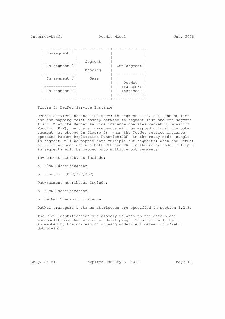
+--------------+--------------+--------------+ | In-segment 1 | | | | | | | +--------------+ Segment | | | In-segment 2 | | Out-segment | | | Mapping | | +--------------+ | +-----------+ | In-segment 3 | Base | | | | | | | DetNet | +--------------+ | | Transport | | In-segment 3 | | | Instance 1| | | | +-----------+ +--------------+--------------+--------------+
Figure 5: DetNet Service Instance
DetNet Service Instance includes: in-segment list, out-segment list and the mapping relationship between in-segment list and out-segment list. When the DetNet service instance operates Packet Elimination Function(PEF), multiple in-segments will be mapped onto single out- segment (as showed in figure 4); when the DetNet service instance operates Packet Replication Function(PRF) in the relay node, single in-segment will be mapped onto multiple out-segments; When the DetNet service instance operate both PEF and PRF in the relay node, multiple in-segments will be mapped onto multiple out-segments.
In-segment attributes include:
o Flow Identification
o Function (PRF/PEF/POF)
Out-segment attributes include:
o Flow Identification
o DetNet Transport Instance
DetNet transport instance attributes are specified in section 5.2.3.
The Flow Identification are closely related to the data plane encapsulations that are under developing. This part will be augmented by the corresponding yang model(ietf-detnet-mpls/ietf- detnet-ip).
Geng, et al. Expires January 3, 2019 [Page 11]

Internet-Draft DetNet Model July 2018
5.2.3. DetNet Transport Instance
DetNet Transport Instance (DTI) covers the functions of DetNet transport layer, it describes the DetNet tunnel that is used to transmit DetNet flows between DetNet service instances.
DetNet Transport Instance attributes include:
The tunnel attributes are closely related to the data plane encapsulations that are under developing. This part will be augmented by the corresponding yang model(ietf-detnet-mpls/ietf- detnet-ip).
6. DetNet Yang Structure
6.1. DetNet Topology Model Tree Diagram
module: ietf-te-detnet-topology augment /nw:networks/nw:network/nw:node: +--rw detnet-performance-metric-attributes | +--rw maximum-detnet-reservable-bandwidth | | +--rw te-bandwidth | | +--rw (technology)? | | +--:(generic) | | +--rw generic? te-bandwidth | +--rw reserved-detnet-bandwidth | | +--rw te-bandwidth | | +--rw (technology)? | | +--:(generic) | | +--rw generic? te-bandwidth | +--rw available-detnet-bandwidth | | +--rw te-bandwidth | | +--rw (technology)? | | +--:(generic) | | +--rw generic? te-bandwidth | +--rw minimum-detnet-device-delay? uint32 | +--rw maximum-detnet-device-delay? uint32 +--rw detnet-queuing-management-algorithm +--rw queuing-management-algorithm? enumeration augment /nw:networks/nw:network/nt:link: +--rw detnet-node-type | +--rw detnet-node-type? enumeration +--rw detnet-resource-reservation-attributes | +--rw MaxFanInPorts? uint32 | +--rw MaxPacketSize? uint32 | +--rw MaxDetNetClasses? uint32 +--rw detnet-elimination-capability? boolean +--rw detnet-replication-capability? boolean
Geng, et al. Expires January 3, 2019 [Page 12]
Internet-Draft DetNet Model July 2018
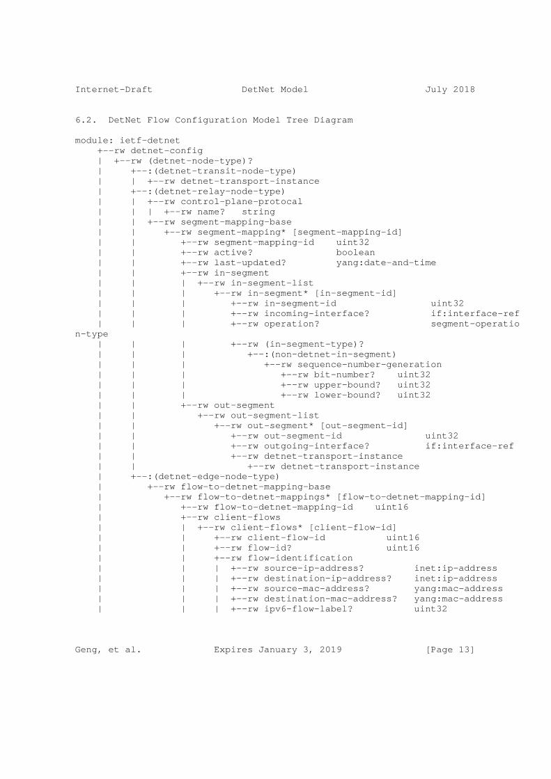
6.2. DetNet Flow Configuration Model Tree Diagram
module: ietf-detnet +--rw detnet-config | +--rw (detnet-node-type)? | +--:(detnet-transit-node-type) | | +--rw detnet-transport-instance | +--:(detnet-relay-node-type) | | +--rw control-plane-protocal | | | +--rw name? string | | +--rw segment-mapping-base | | +--rw segment-mapping* [segment-mapping-id] | | +--rw segment-mapping-id uint32 | | +--rw active? boolean | | +--rw last-updated? yang:date-and-time | | +--rw in-segment | | | +--rw in-segment-list | | | +--rw in-segment* [in-segment-id] | | | +--rw in-segment-id uint32 | | | +--rw incoming-interface? if:interface-ref | | | +--rw operation? segment-operation-type | | | +--rw (in-segment-type)? | | | +--:(non-detnet-in-segment) | | | +--rw sequence-number-generation | | | +--rw bit-number? uint32 | | | +--rw upper-bound? uint32 | | | +--rw lower-bound? uint32 | | +--rw out-segment | | +--rw out-segment-list | | +--rw out-segment* [out-segment-id] | | +--rw out-segment-id uint32 | | +--rw outgoing-interface? if:interface-ref | | +--rw detnet-transport-instance | | +--rw detnet-transport-instance | +--:(detnet-edge-node-type) | +--rw flow-to-detnet-mapping-base | +--rw flow-to-detnet-mappings* [flow-to-detnet-mapping-id] | +--rw flow-to-detnet-mapping-id uint16 | +--rw client-flows | | +--rw client-flows* [client-flow-id] | | +--rw client-flow-id uint16 | | +--rw flow-id? uint16 | | +--rw flow-identification | | | +--rw source-ip-address? inet:ip-address | | | +--rw destination-ip-address? inet:ip-address | | | +--rw source-mac-address? yang:mac-address | | | +--rw destination-mac-address? yang:mac-address | | | +--rw ipv6-flow-label? uint32
Geng, et al. Expires January 3, 2019 [Page 13]

Internet-Draft DetNet Model July 2018
| | | +--rw mpls-label? rt-types:mpls-label | | +--rw traffic-specification | | +--rw max-packets-per-interval? uint16 | | +--rw max-packet-size? uint16 | | +--rw queuing-algorithm-selection? uint8 | +--rw detnet-service-instance | +--rw control-plane-protocal | | +--rw name? string | +--rw segment-mapping-base | +--rw segment-mapping* [segment-mapping-id] | +--rw segment-mapping-id uint32 | +--rw active? boolean | +--rw last-updated? yang:date-and-time | +--rw in-segment | | +--rw in-segment-list | | +--rw in-segment* [in-segment-id] | | +--rw in-segment-id uint32 | | +--rw incoming-interface? if:interface-ref | | +--rw operation? segment-operation-type | | +--rw (in-segment-type)? | | +--:(non-detnet-in-segment) | | +--rw sequence-number-generation | | +--rw bit-number? uint32 | | +--rw upper-bound? uint32 | | +--rw lower-bound? uint32 | +--rw out-segment | +--rw out-segment-list | +--rw out-segment* [out-segment-id] | +--rw out-segment-id uint32 | +--rw outgoing-interface? if:interface-ref | +--rw detnet-transport-instance | +--rw detnet-transport-instance +--ro detnet-state +--ro (detnet-node-type)? +--:(detnet-transit-node-type) | +--ro detnet-transport-instance +--:(detnet-relay-node-type) | +--ro control-plane-protocal | | +--ro name? string | +--ro segment-mapping-base | +--ro segment-mapping* [segment-mapping-id] | +--ro segment-mapping-id uint32 | +--ro active? boolean | +--ro last-updated? yang:date-and-time | +--ro in-segment | | +--ro in-segment-list | | +--ro in-segment* [in-segment-id] | | +--ro in-segment-id uint32
Geng, et al. Expires January 3, 2019 [Page 14]

Internet-Draft DetNet Model July 2018
| | +--ro incoming-interface? if:interface-ref | | +--ro operation? segment-operation-type | | +--ro (in-segment-type)? | | +--:(non-detnet-in-segment) | | +--ro sequence-number-generation | | +--ro bit-number? uint32 | | +--ro upper-bound? uint32 | | +--ro lower-bound? uint32 | +--ro out-segment | +--ro out-segment-list | +--ro out-segment* [out-segment-id] | +--ro out-segment-id uint32 | +--ro outgoing-interface? if:interface-ref | +--ro detnet-transport-instance | +--ro detnet-transport-instance +--:(detnet-edge-node-type) +--ro flow-to-detnet-mapping-base +--ro flow-to-detnet-mappings* [flow-to-detnet-mapping-id] +--ro flow-to-detnet-mapping-id uint16 +--ro client-flows | +--ro client-flows* [client-flow-id] | +--ro client-flow-id uint16 | +--ro flow-id? uint16 | +--ro flow-identification | | +--ro source-ip-address? inet:ip-address | | +--ro destination-ip-address? inet:ip-address | | +--ro source-mac-address? yang:mac-address | | +--ro destination-mac-address? yang:mac-address | | +--ro ipv6-flow-label? uint32 | | +--ro mpls-label? rt-types:mpls-label | +--ro traffic-specification | +--ro max-packets-per-interval? uint16 | +--ro max-packet-size? uint16 | +--ro queuing-algorithm-selection? uint8 +--ro detnet-service-instance +--ro control-plane-protocal | +--ro name? string +--ro segment-mapping-base +--ro segment-mapping* [segment-mapping-id] +--ro segment-mapping-id uint32 +--ro active? boolean +--ro last-updated? yang:date-and-time +--ro in-segment | +--ro in-segment-list | +--ro in-segment* [in-segment-id] | +--ro in-segment-id uint32 | +--ro incoming-interface? if:interface-ref | +--ro operation? segment-operation-type
Geng, et al. Expires January 3, 2019 [Page 15]

Internet-Draft DetNet Model July 2018
| +--ro (in-segment-type)? | +--:(non-detnet-in-segment) | +--ro sequence-number-generation | +--ro bit-number? uint32 | +--ro upper-bound? uint32 | +--ro lower-bound? uint32 +--ro out-segment +--ro out-segment-list +--ro out-segment* [out-segment-id] +--ro out-segment-id uint32 +--ro outgoing-interface? if:interface-ref +--ro detnet-transport-instance +--ro detnet-transport-instance
6.3. DetNet Device Configuration Model Tree Diagram
module: ietf-detnet-device +--rw detnet-device-config | +--rw PEF-enabled? boolean | +--rw PRF-enabled? boolean | +--rw POF-enabled? boolean | +--rw detnet-interfaces +--ro detnet-device-states +--ro PEF-enabled? boolean +--ro PRF-enabled? boolean +--ro POF-enabled? boolean +--ro detnet-interfaces
7. DetNet YANG Model
7.1. DetNet Topology YANG Model
<CODE BEGINS> file "[email protected]" module ietf-detnet-topology { namespace "urn:ietf:params:xml:ns:yang:ietf-detnet-topology"; prefix "detnet-topo";
import ietf-te-types { prefix "te-types"; }
import ietf-routing-types { prefix "rt-types"; }
import ietf-te-topology { prefix "tet";
Geng, et al. Expires January 3, 2019 [Page 16]

Internet-Draft DetNet Model July 2018
}
import ietf-network { prefix "nw"; }
import ietf-network-topology { prefix "nt"; }
organization "IETF Deterministic Networking(detnet)Working Group";
contact "WG Web: <http://tools.ietf.org/wg/detnet/> WG List: <mailto:[email protected]>
WG Chair: Lou Berger <mailto:[email protected]>
Editor: Xuesong Geng <mailto:[email protected]>
Editor: Mach Chen <mailto:[email protected]>
Eidtor: Reshad Rahman <[email protected]>";
description "This YAGN module augments the ’ietf-te-topology’ module with detnet capability data for detnet configuration";
revision "2018-01-15" { description "Initial revision"; reference "RFC XXXX: YANG Data Model for DetNet Topologies"; //RFC Ed.: replace XXXX with actual RFC number and remove // this note }
grouping detnet-link-info-attributes{ description "DetNet capability attributes in a DetNet topology"; container detnet-performance-metric-attributes{ description "Link performance information in real time."; uses detnet-performance-metric-attributes;
Geng, et al. Expires January 3, 2019 [Page 17]
Internet-Draft DetNet Model July 2018
} container detnet-queuing-management-algorithm{ description "Detnet queuing management algorithm used in output queue"; uses detnet-queuing-management-algorithm; } }
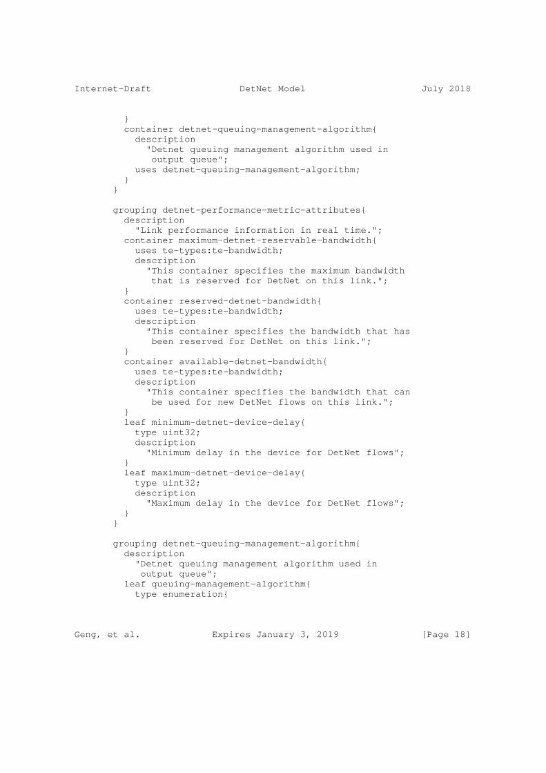
grouping detnet-performance-metric-attributes{ description "Link performance information in real time."; container maximum-detnet-reservable-bandwidth{ uses te-types:te-bandwidth; description "This container specifies the maximum bandwidth that is reserved for DetNet on this link."; } container reserved-detnet-bandwidth{ uses te-types:te-bandwidth; description "This container specifies the bandwidth that has been reserved for DetNet on this link."; } container available-detnet-bandwidth{ uses te-types:te-bandwidth; description "This container specifies the bandwidth that can be used for new DetNet flows on this link."; } leaf minimum-detnet-device-delay{ type uint32; description "Minimum delay in the device for DetNet flows"; } leaf maximum-detnet-device-delay{ type uint32; description "Maximum delay in the device for DetNet flows"; } }
grouping detnet-queuing-management-algorithm{ description "Detnet queuing management algorithm used in output queue"; leaf queuing-management-algorithm{ type enumeration{
Geng, et al. Expires January 3, 2019 [Page 18]

Internet-Draft DetNet Model July 2018
enum credit-based-shaping{ reference "IEEE P802.1 Qav"; } enum time-aware-shaping{ reference "IEEE P802.1 Qbv"; } enum cyclic-queuing-and-forwarding{ reference "IEEE P802.1 Qch"; } enum asynchronous-traffic-shaping{ reference "IEEE P802.1 Qcr"; } } description "Detnet queuing management algorithm type"; } }
grouping detnet-node-info-attributes{ description "DetNet capability attributes in a DetNet node"; container detnet-node-type{ description "Three types of DetNet nodes"; reference "draft-ietf-detnet-architecture-03: Deterministic Networking Architecture"; uses detnet-node-type; } container detnet-resource-reservation-attributes{ description "Attributes about resource reservation for DetNet flows"; uses detnet-resource-reservation-attributes; } leaf detnet-elimination-capability{ type boolean; description "This node is able to do DetNet packet elimination"; } leaf detnet-replication-capability{ type boolean;
Geng, et al. Expires January 3, 2019 [Page 19]

Internet-Draft DetNet Model July 2018
description "This node is able to do DetNet packet replication"; } }
grouping detnet-node-type{ description "This grouping defines three types of DetNet nodes"; reference "draft-ietf-detnet-architecture-03:Deterministic Networking Architecture"; leaf detnet-node-type{ type enumeration{ enum edge-node{ description "An instance of a DetNet relay node that includes either a DetNet service layer proxy function for DetNet service protection (e.g. the addition or removal of packet sequencing information) for one or more end systems, or starts or terminate congestion protection at the DetNet transport layer,analogous to a Label Edge Router (LER)."; } enum relay-node{ description "A DetNet node including a service layer function that interconnects different DetNet transport layer paths to provide service protection.A DetNet relay node can be a bridge, a router, a firewall, or any other system that participates in the DetNet service layer. It typically incorporates DetNet transport layer functions as well, in which case it is collocated with a transit node."; } enum transit-node{ description "A node operating at the DetNet transport layer, that utilizes link layer and/or network layer switching across multiple links and/or sub-networks to provide paths for DetNet service layer functions.Optionally provides congestion protection over those paths.An MPLS LSR is an example of a DetNet transit node."; } }
Geng, et al. Expires January 3, 2019 [Page 20]

Internet-Draft DetNet Model July 2018
description "The type this node belongs to, which also determines the role the node can play in DetNet "; } }
grouping detnet-resource-reservation-attributes{ description "This grouping describs reservation operation for the entire device"; leaf MaxFanInPorts{ type uint32; description "maximum number of fan-in ports in the device"; } leaf MaxPacketSize{ type uint32; description "maximum Packet size the device allows"; } leaf MaxDetNetClasses{ type uint32; description "maximum number of traffic classes that can be reserved for DetNet"; } }
augment "/nw:networks/nw:network/nw:node" { when "../nw:network-types/tet:te-topology" { description ""; } description "Advertised DetNet link information attributes."; uses detnet-link-info-attributes; }
augment "/nw:networks/nw:network/nt:link" { when "../nw:network-types/tet:te-topology" { description ""; } description "Advertised DetNet node information attributes."; uses detnet-node-info-attributes;
Geng, et al. Expires January 3, 2019 [Page 21]

Internet-Draft DetNet Model July 2018
} } <CODE ENDS>
7.2. DetNet Flow Configuration YANG Model
<CODE BEGINS> file "[email protected]" module ietf-flow-detnet { namespace "urn:ietf:params:xml:ns:yang:ietf-flow-detnet"; prefix "detnet";
import ietf-yang-types { prefix "yang"; }
import ietf-interfaces { prefix "if"; }
import ietf-inet-types{ prefix "inet"; }
import ietf-routing-types { prefix "rt-types"; }
organization "IETF DetNet Working Group";
contact "WG Web: <http://tools.ietf.org/wg/detnet/> WG List: <mailto: [email protected]> WG Chair: Lou Berger <mailto:[email protected]> Editor: Xuesong Geng <mailto:[email protected]> Editor: Mach Chen <mailto:[email protected]> Editor: Zhenqiang Li <[email protected]> Eidtor: Reshad Rahman <[email protected]>"; description "This YAGN module describes the parameters needed for DetNet configuration";
revision "2018-06-26" { description "Latest revision for ietf-detnet";
Geng, et al. Expires January 3, 2019 [Page 22]

Internet-Draft DetNet Model July 2018
reference "RFC XXXX: YANG Data Model for ietf-detnet"; }
identity detnet-node-type { description "base detnet-node-type"; }
identity detnet-edge-node-type { base detnet-node-type; description "An instance of a DetNet relay node that includes either a DetNet service layer proxy function for DetNet service protection (e.g. the addition or removal of packet sequencing information) for one or more end systems, or starts or terminate congestion protection at the DetNet transport layer,analogous to a Label Edge Router (LER)."; }
identity detnet-relay-node-type { base detnet-node-type; description "A DetNet node including a service layer function that interconnects different DetNet transport layer paths to provide service protection.A DetNet relay node can be a bridge, a router, a firewall, or any other system that participates in the DetNet service layer. It typically incorporates DetNet transport layer functions as well, in which case it is collocated with a transit node."; }
identity detnet-transit-node-type { base detnet-node-type; description "A node operating at the DetNet transport layer, that utilizes link layer and/or network layer switching across multiple links and/or sub-networks to provide paths for DetNet service layer functions.Optionally provides congestion protection over those paths.An MPLS LSR is an example of a DetNet transit node."; }
Geng, et al. Expires January 3, 2019 [Page 23]

Internet-Draft DetNet Model July 2018
identity detnet-transport-layer { description "The layer that optionally provides congestion protection for DetNet flows over paths provided by the underlying network."; }
identity detnet-service-layer { description "The layer at which service protection is provided, either packet sequencing, replication, and elimination or packet encoding"; }
typedef segment-operation-type { type enumeration { enum replication { description "One of the Packet Replication and Elimination Function (PREF), which does the packet elimination processing of DetNet flow packets in edge or relay nodes."; } enum elimination { description "One of the Packet Replication and Elimination Function (PREF), which does the packet replication processing of DetNet flow packets in edge or relay nodes."; } enum elimination-and-replication { description "One of the Packet Replication and Elimination Function (PREF), which does the packet elimination and replication processing of DetNet flow packets in edge or relay nodes."; } } description ""; } grouping detnet-transport-instance{ description ""; container detnet-transport-instance{
Geng, et al. Expires January 3, 2019 [Page 24]

Internet-Draft DetNet Model July 2018
description "the contents of detnet transport instance depend on data plane solution of this detnet domain"; } }
grouping sequence-number-generation { description ""; leaf bit-number{ type uint32; description ""; } leaf upper-bound { type uint32; description ""; } leaf lower-bound { type uint32; description ""; } }
grouping in-segment-content { description "in-segment grouping in the detnet service layer"; container in-segment-list { description ""; list in-segment { key "in-segment-id"; description ""; leaf in-segment-id{ type uint32; description ""; } leaf incoming-interface { type if:interface-ref; description "Name of the incoming interface.";
Geng, et al. Expires January 3, 2019 [Page 25]

Internet-Draft DetNet Model July 2018
} leaf operation { type segment-operation-type; description ""; } choice in-segment-type{ description ""; case non-detnet-in-segment{ description ""; container sequence-number-generation{ description ""; uses sequence-number-generation; } } } } } }
grouping out-segment-content{ description ""; container out-segment-list { description ""; list out-segment{ key "out-segment-id"; description ""; leaf out-segment-id{ type uint32; description ""; } leaf outgoing-interface { type if:interface-ref; description "Name of the outgoing interface."; } container detnet-transport-instance{ description ""; uses detnet-transport-instance; }
Geng, et al. Expires January 3, 2019 [Page 26]

Internet-Draft DetNet Model July 2018
} } }
grouping segment-mapping-metadata{ description ""; leaf active { type boolean; description "Whether the segment mapping base is active or not"; } leaf last-updated { type yang:date-and-time; description "Time stamp of the last modification of the mapping. If the mapping was never modified, it is the time when the mapping was inserted into the RIB."; } }
grouping detnet-service-instance{ description ""; container control-plane-protocal{ description ""; leaf name{ type string; description "the name of the control plane protocal"; } } container segment-mapping-base{ description ""; list segment-mapping{ key "segment-mapping-id"; description ""; leaf segment-mapping-id{ type uint32; description ""; } uses segment-mapping-metadata;
Geng, et al. Expires January 3, 2019 [Page 27]

Internet-Draft DetNet Model July 2018
container in-segment{ description ""; uses in-segment-content; } container out-segment{ description ""; uses out-segment-content; } } } }
grouping flow-identfication { description "DetNet flow identification"; reference "draft-farkas-detnet-flow-information-model"; leaf source-ip-address { type inet:ip-address; description "Source IP address"; } leaf destination-ip-address { type inet:ip-address; description "Destination IP address"; } leaf source-mac-address { type yang:mac-address; description "Source MAC address"; } leaf destination-mac-address { type yang:mac-address; description "Destination MAC address"; } leaf ipv6-flow-label { type uint32; description "ipv6 flow label"; } leaf mpls-label { type rt-types:mpls-label; description "MPLS Label";
Geng, et al. Expires January 3, 2019 [Page 28]

Internet-Draft DetNet Model July 2018
} }
grouping traffic-specification{ description "traffic-specification specifies how the Source transmits packets for the flow. This is the promise/request of the Source to the network. The network uses this traffic specification to allocate resources and adjust queue parameters in network nodes."; reference "draft-farkas-detnet-flow-information-model"; leaf max-packets-per-interval{ type uint16; description "max-packets-per-interval specifies the maximum number of packets that the application shall transmit in one Interval."; } leaf max-packet-size{ type uint16; description "max-packet-size specifies maximum packet size that the Source will transmit"; } leaf queuing-algorithm-selection{ type uint8; description ""; } }
grouping client-flow{ description ""; leaf flow-id{ type uint16; description ""; } container flow-identification{ description ""; uses flow-identfication; } container traffic-specification{ description
Geng, et al. Expires January 3, 2019 [Page 29]

Internet-Draft DetNet Model July 2018
""; uses traffic-specification; } }
grouping flow-to-detnet-mapping{ description ""; container flow-to-detnet-mapping-base{ description ""; list flow-to-detnet-mappings{ key "flow-to-detnet-mapping-id"; description ""; leaf flow-to-detnet-mapping-id{ type uint16; description ""; } container client-flows{ description ""; list client-flows{ key "client-flow-id"; description ""; leaf client-flow-id{ type uint16; description ""; } uses client-flow; } } container detnet-service-instance{ description ""; uses detnet-service-instance; } } } }
/* Congfiguration Data */
container detnet-config{ description
Geng, et al. Expires January 3, 2019 [Page 30]

Internet-Draft DetNet Model July 2018
""; choice detnet-node-type{ description ""; case detnet-transit-node-type{ description ""; uses detnet-transport-instance; } case detnet-relay-node-type{ description ""; uses detnet-service-instance; } case detnet-edge-node-type{ description ""; uses flow-to-detnet-mapping; } } }
/* Status Data */
container detnet-state{ config "false"; description ""; choice detnet-node-type{ description ""; case detnet-transit-node-type{ description ""; uses detnet-transport-instance; } case detnet-relay-node-type{ description ""; uses detnet-service-instance; } case detnet-edge-node-type{ description ""; uses flow-to-detnet-mapping; } } }
Geng, et al. Expires January 3, 2019 [Page 31]

Internet-Draft DetNet Model July 2018
} <CODE ENDS>
7.3. DetNet Device Configuration Yang Model
<CODE BEGINS> file "[email protected]" module ietf-detnet-device { namespace "urn:ietf:params:xml:ns:yang:ietf-detnet-device"; prefix "detnet-device";
organization "IETF DetNet Working Group"; contact "WG Web: <http://tools.ietf.org/wg/detnet/> WG List: <mailto: [email protected]> WG Chair: Lou Berger <mailto:[email protected]> Editor: Xuesong Geng <mailto:[email protected]> Editor: Mach Chen <mailto:[email protected]> Editor: Zhenqiang Li <[email protected]> Eidtor: Reshad Rahman <[email protected]>"; description "This YAGN module describes the parameters needed for DetNet configuration in device"; revision "2018-06-29" { description "Latest revision for ietf-detnet-device"; reference "RFC XXXX: YANG Data Model for ietf-detnet-device"; }
grouping detnet-device-parameters { description "Parameters of queuing, bandwidth on device."; leaf PEF-enabled { type boolean; description "A Packet Elimination Function (PEF) eliminates duplicate copies of packets to prevent excess packets flooding the network or duplicate packets being sent out of the DetNet domain. PEF can be implemented by an edge node, a relay node, or an end system."; } leaf PRF-enabled { type boolean;
Geng, et al. Expires January 3, 2019 [Page 32]

Internet-Draft DetNet Model July 2018
description "A Packet Replication Function (PRF) replicates DetNet flow packets and forwards them to one or more next hops in the DetNet domain. The number of packet copies sent to each next hop is a DetNet flow specific parameter at the node doing the replication. PRF can be implemented by an edge node, a relay node, or an end system."; } leaf POF-enabled { type boolean; description "A Packet Ordering Function (POF) re-orders packets within a DetNet flow that are received out of order. This function can be implemented by an edge node, a relay node, or an end system."; }
container detnet-interfaces { description "A list of interfaces that are DetNet enabled."; //Edior notes: This is heavily related to the YANG models //defined in IEEE Qcw project. } }
container detnet-device-config { description "DetNet device configurations."; uses detnet-device-parameters; }
container detnet-device-states { config false; description "DetNet device states."; uses detnet-device-parameters; } }<CODE ENDS>
8. DetNet Configuration Model Classification
This section defines three classes of DetNet configuration model: fully distributed configuration model, fully centralized configuration model, hybrid configuration model, based on different network architectures, showing how configuration information exchanges between various entities in the network.
Geng, et al. Expires January 3, 2019 [Page 33]

Internet-Draft DetNet Model July 2018
8.1. Fully Distributed Configuration Model
In a fully distributed configuration model, UNI information is transmitted over DetNet UNI protocol from the user side to the network side; then UNI information and network configuration information propagate in the network over distributed control plane protocol. For example:
1) IGP collects topology information and DetNet capabilities of network([I-D.geng-detnet-info-distribution]);
2) Control Plane of the Edge Node(Ingress) receives a flow establishment request from UNI and calculates a/some valid path(s);
3) Using RSVP-TE, Edge Node(Ingress) sends a PATH message with explicit route. After receiving the PATH message, the other Edge Node(Egress) sends a Resv message with distributed label and resource reservation request.
Current distributed control plane protocol,e.g., RSVP-TE[RFC3209], SRP[IEEE802.1Qcc], can only reserve bandwidth along the path, while the configuration of a fine-grained schedule, e.g.,Time Aware Shaping(TAS) defined in [IEEE802.1Qbv], is not supported.
The fully distributed configuration model is not covered by this draft. It should be discussed in the future DetNet control plane work.
8.2. Fully Centralized Configuration Model
In the fully centralized configuration model, UNI information is transmitted from Centralized User Configuration (CUC) to Centralized Network Configuration(CNC). Configurations of routers for DetNet flows are performed by CNC with network management protocol.For example:
1) CNC collects topology information and DetNet capability of network through Netconf;
2) CNC receives a flow establishment request from UNI and calculates a/some valid path(s);
3) CNC configures the devices along the path for flow transmission.
Geng, et al. Expires January 3, 2019 [Page 34]
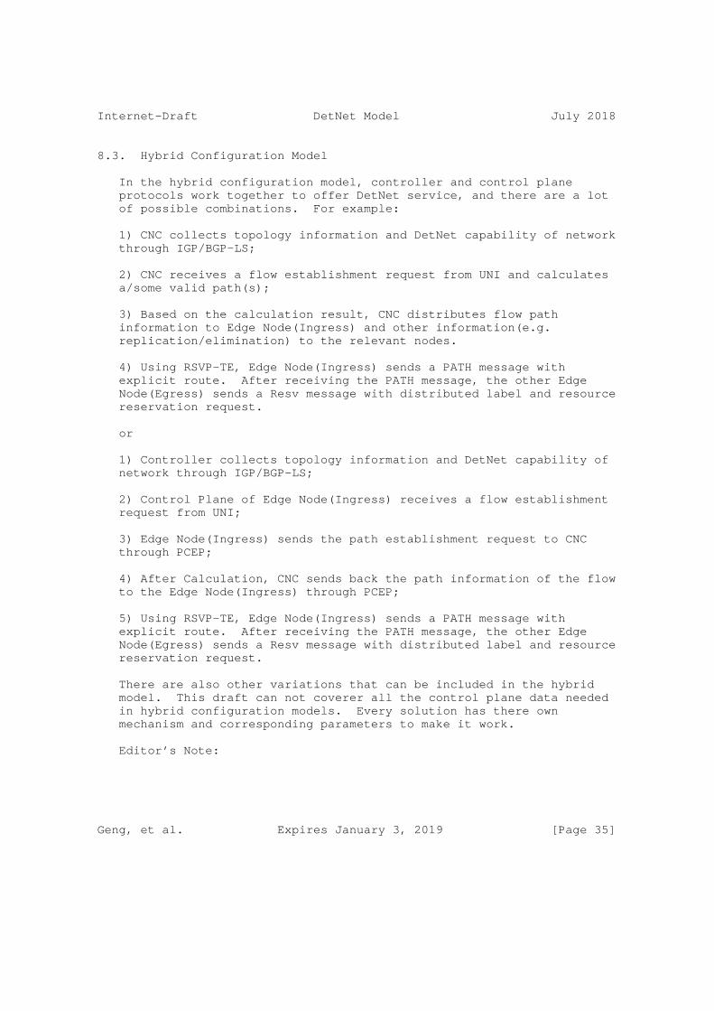
Internet-Draft DetNet Model July 2018
8.3. Hybrid Configuration Model
In the hybrid configuration model, controller and control plane protocols work together to offer DetNet service, and there are a lot of possible combinations. For example:
1) CNC collects topology information and DetNet capability of network through IGP/BGP-LS;
2) CNC receives a flow establishment request from UNI and calculates a/some valid path(s);
3) Based on the calculation result, CNC distributes flow path information to Edge Node(Ingress) and other information(e.g. replication/elimination) to the relevant nodes.
4) Using RSVP-TE, Edge Node(Ingress) sends a PATH message with explicit route. After receiving the PATH message, the other Edge Node(Egress) sends a Resv message with distributed label and resource reservation request.
or
1) Controller collects topology information and DetNet capability of network through IGP/BGP-LS;
2) Control Plane of Edge Node(Ingress) receives a flow establishment request from UNI;
3) Edge Node(Ingress) sends the path establishment request to CNC through PCEP;
4) After Calculation, CNC sends back the path information of the flow to the Edge Node(Ingress) through PCEP;
5) Using RSVP-TE, Edge Node(Ingress) sends a PATH message with explicit route. After receiving the PATH message, the other Edge Node(Egress) sends a Resv message with distributed label and resource reservation request.
There are also other variations that can be included in the hybrid model. This draft can not coverer all the control plane data needed in hybrid configuration models. Every solution has there own mechanism and corresponding parameters to make it work.
Editor’s Note:
Geng, et al. Expires January 3, 2019 [Page 35]

Internet-Draft DetNet Model July 2018
1. There are a lot of optional DetNet configuration models, and different scenario in different use case can choose one of them based on its conditions. Maybe next step of the work is to pick up one or more typical scenarios and give a practical solution.
2. [IEEE802.1Qcc] also defines three TSN configuration models: fully-centralized model, fully-distributed model, centralized Network / distributed User Model. This section defines the configuration model roughly the same, to keep the design of L2 and L3 in the same structure. Hybrid configuration model is slightly different from the ’centralized Network / distributed User Model’. The hybrid configuration model intends to contain more variations.
9. IANA Considerations
This document makes no request of IANA.
Note to RFC Editor: this section may be removed on publication as an RFC.
10. Security Considerations
11. Acknowledgements
12. References
12.1. Normative References
[I-D.dt-detnet-dp-sol] Korhonen, J., Andersson, L., Jiang, Y., Finn, N., Varga, B., Farkas, J., Bernardos, C., Mizrahi, T., and L. Berger, "DetNet Data Plane Encapsulation", draft-dt-detnet-dp- sol-02 (work in progress), September 2017.
[I-D.ietf-detnet-architecture] Finn, N., Thubert, P., Varga, B., and J. Farkas, "Deterministic Networking Architecture", draft-ietf- detnet-architecture-05 (work in progress), May 2018.
[I-D.ietf-detnet-flow-information-model] Farkas, J., Varga, B., [email protected], r., Jiang, Y., and Y. Zha, "DetNet Flow Information Model", draft- ietf-detnet-flow-information-model-01 (work in progress), March 2018.
Geng, et al. Expires January 3, 2019 [Page 36]

Internet-Draft DetNet Model July 2018
[RFC2119] Bradner, S., "Key words for use in RFCs to Indicate Requirement Levels", BCP 14, RFC 2119, DOI 10.17487/RFC2119, March 1997, <https://www.rfc-editor.org/info/rfc2119>.
12.2. Informative References
[I-D.geng-detnet-info-distribution] Geng, X., Chen, M., and Z. Li, "IGP-TE Extensions for DetNet Information Distribution", draft-geng-detnet-info- distribution-02 (work in progress), March 2018.
[I-D.ietf-detnet-use-cases] Grossman, E., "Deterministic Networking Use Cases", draft- ietf-detnet-use-cases-16 (work in progress), May 2018.
[I-D.ietf-teas-yang-te] Saad, T., Gandhi, R., Liu, X., Beeram, V., Shah, H., and I. Bryskin, "A YANG Data Model for Traffic Engineering Tunnels and Interfaces", draft-ietf-teas-yang-te-15 (work in progress), June 2018.
[I-D.ietf-teas-yang-te-topo] Liu, X., Bryskin, I., Beeram, V., Saad, T., Shah, H., and O. Dios, "YANG Data Model for Traffic Engineering (TE) Topologies", draft-ietf-teas-yang-te-topo-17 (work in progress), June 2018.
[I-D.thubert-tsvwg-detnet-transport] Thubert, P., "A Transport Layer for Deterministic Networks", draft-thubert-tsvwg-detnet-transport-01 (work in progress), October 2017.
[I-D.varga-detnet-service-model] Varga, B. and J. Farkas, "DetNet Service Model", draft- varga-detnet-service-model-02 (work in progress), May 2017.
[IEEE802.1CB] "IEEE, "Frame Replication and Elimination for Reliability (IEEE Draft P802.1CB)", 2017, <http://www.ieee802.org/1/files/private/cb-drafts/>.", 2016.
[IEEE802.1Q-2014] "IEEE, "IEEE Std 802.1Q Bridges and Bridged Networks", 2014, <http://ieeexplore.ieee.org/document/6991462/>.", 2014.
Geng, et al. Expires January 3, 2019 [Page 37]

Internet-Draft DetNet Model July 2018
[IEEE802.1Qbu] "IEEE, "IEEEE Std 802.1Qbu Bridges and Bridged Networks - Amendment 26: Frame Preemption", 2016, <http://ieeexplore.ieee.org/document/7553415/>.", 2016.
[IEEE802.1Qbv] "IEEE, "IEEE Std 802.1Qbu Bridges and Bridged Networks - Amendment 25: Enhancements for Scheduled Traffic", 2015, <http://ieeexplore.ieee.org/document/7572858/>.", 2016.
[IEEE802.1Qcc] "IEEE, "Stream Reservation Protocol (SRP) Enhancements and Performance Improvements (IEEE Draft P802.1Qcc)", 2017, <http://www.ieee802.org/1/files/private/cc-drafts/>.".
[IEEE802.1Qch] "IEEE, "Cyclic Queuing and Forwarding (IEEE Draft P802.1Qch)", 2017, <http://www.ieee802.org/1/files/private/ch-drafts/>.", 2016.
[IEEE802.1Qci] "IEEE, "Per-Stream Filtering and Policing (IEEE Draft P802.1Qci)", 2016, <http://www.ieee802.org/1/files/private/ci-drafts/>.", 2016.
[RFC3209] Awduche, D., Berger, L., Gan, D., Li, T., Srinivasan, V., and G. Swallow, "RSVP-TE: Extensions to RSVP for LSP Tunnels", RFC 3209, DOI 10.17487/RFC3209, December 2001, <https://www.rfc-editor.org/info/rfc3209>.
[RFC4875] Aggarwal, R., Ed., Papadimitriou, D., Ed., and S. Yasukawa, Ed., "Extensions to Resource Reservation Protocol - Traffic Engineering (RSVP-TE) for Point-to- Multipoint TE Label Switched Paths (LSPs)", RFC 4875, DOI 10.17487/RFC4875, May 2007, <https://www.rfc-editor.org/info/rfc4875>.
Authors’ Addresses
Xuesong Geng Huawei
Email: [email protected]
Geng, et al. Expires January 3, 2019 [Page 38]

Internet-Draft DetNet Model July 2018
Mach(Guoyi) Chen Huawei
Email: [email protected]
Zhenqiang China Mobile
Email: [email protected]
Reshad Cisco
Geng, et al. Expires January 3, 2019 [Page 39]

Network Working Group L. GengInternet-Draft L. WangIntended status: Informational China MobileExpires: January 3, 2019 L. Qiang Huawei Technologies July 2, 2018
Technical Requirements of Bounded Latency in Large-scale DetNet Deployment draft-geng-detnet-requirements-bounded-latency-00
Abstract
This document summarizes the technical requirements of bounded latency of DetNet system in large-scale deployment.
Status of This Memo
This Internet-Draft is submitted in full conformance with the provisions of BCP 78 and BCP 79.
Internet-Drafts are working documents of the Internet Engineering Task Force (IETF). Note that other groups may also distribute working documents as Internet-Drafts. The list of current Internet- Drafts is at https://datatracker.ietf.org/drafts/current/.
Internet-Drafts are draft documents valid for a maximum of six months and may be updated, replaced, or obsoleted by other documents at any time. It is inappropriate to use Internet-Drafts as reference material or to cite them other than as "work in progress."
This Internet-Draft will expire on January 3, 2019.
Copyright Notice
Copyright (c) 2018 IETF Trust and the persons identified as the document authors. All rights reserved.
This document is subject to BCP 78 and the IETF Trust’s Legal Provisions Relating to IETF Documents (https://trustee.ietf.org/license-info) in effect on the date of publication of this document. Please review these documents carefully, as they describe your rights and restrictions with respect to this document. Code Components extracted from this document must include Simplified BSD License text as described in Section 4.e of the Trust Legal Provisions and are provided without warranty as described in the Simplified BSD License.
Geng, et al. Expires January 3, 2019 [Page 1]

Internet-DraTechnical Requirements of DetNet Deployment in La July 2018
Table of Contents
1. Introduction . . . . . . . . . . . . . . . . . . . . . . . . 2 1.1. Requirements Language . . . . . . . . . . . . . . . . . . 3 1.2. Terminology & Abbreviations . . . . . . . . . . . . . . . 3 2. End-to-end bounded latency requirements . . . . . . . . . . . 3 3. Tolerance of time deviation . . . . . . . . . . . . . . . . . 4 4. Massive number of deterministic flows . . . . . . . . . . . . 4 5. Stable jitter with long transmission delay . . . . . . . . . 4 6. IANA Considerations . . . . . . . . . . . . . . . . . . . . . 5 7. Security Considerations . . . . . . . . . . . . . . . . . . . 5 8. Acknowledgements . . . . . . . . . . . . . . . . . . . . . . 5 9. Normative References . . . . . . . . . . . . . . . . . . . . 5 Authors’ Addresses . . . . . . . . . . . . . . . . . . . . . . . 6
1. Introduction
Deterministic Networking (DetNet) enables the transmission of specific data flows in large scale networks with extremely low data loss rates and bounded latency. [draft-ietf-detnet-problem-statement] outlines the problems that need to be resolved in DetNet, and [draft-ietf-detnet-use-cases] presents the use cases in which DetNet deployment is found beneficial and useful.
In DetNet WG, many of the technical requirements and solution have been discussed In order to achieve deterministic networking performance in large-scale network. This mainly include the following aspect.
o DetNet Definition and architecture are discussed in [draft-ietf-detnet-architecture]
o Encapsulation methods are discussed in[draft-ietf-detnet-dp-sol] with specific mechanisms for identification of DetNet services and approaches for reliable transmission (i.e. Replication of packets).
o Security requirements are specially discussed in [draft-ietf-detnet-security].
To some extend, TSN is assumed to be used for Layer 2 underlay for DetNet services to guarantee the bounded latency performance. However, TSN is originally designed for LAN scenario which suffers from scalability problems (i.e. end-to-end time synchronization, sensitive jitter performance subject to transmission latency). Meanwhile, it is also considered challenging to using MPLS/IP encapsulation for DetNet service in which the forwarding plane is purely based on Layer 2 TSN technology. There is yet a document
Geng, et al. Expires January 3, 2019 [Page 2]

Internet-DraTechnical Requirements of DetNet Deployment in La July 2018
which specifically discusses the requirements of bounded latency with an assumption that DetNet runs as an standalone underlay technology rather than an overlay of TSN.
1.1. Requirements Language
The key words "MUST", "MUST NOT", "REQUIRED", "SHALL", "SHALL NOT", "SHOULD", "SHOULD NOT", "RECOMMENDED", "MAY", and "OPTIONAL" in this document are to be interpreted as described in RFC 2119.
1.2. Terminology & Abbreviations
This document uses the terminology defined in [draft-ietf-detnet-architecture].
TSN: Time Sensitive Network
2. End-to-end bounded latency requirements
As [draft-ietf-detnet-dp-sol] declares, there are two types of scenarios considered in DetNet as shown in Figure 1: (i) inter- connect TSN domains scenario, and (ii) native connectivity between DetNet-aware end systems.
+--------------+ +--------------+ | | | | | TSN Domain I +-----------------------------+ TSN Domain II| | | | | +--------------+ +--------------+
(i) Inter-connect TSN Domains
+--------------+ +--------------+ |DetNet Device +---------------------------+DetNet Device | +--------------+ +--------------+
(ii) Native Connectivity between DetNet-aware End Systems
Figure 1: Two Types of DetNet Scenarios
Req 1: Stitching TSN domains with bounded latency.
In scenario (i) TSN islands are bridged through DetNet connections, and time synchronization is required inside each TSN domain. Note that different TSN domains may be misaligned in time and it may not be feasible to achieve end-to-end time synchronization in large scale. It is the DetNet domain who has to maintain the bounded latency performance between the separated TSN domains.
Geng, et al. Expires January 3, 2019 [Page 3]

Internet-DraTechnical Requirements of DetNet Deployment in La July 2018
Req 2: Flexible and fast convergence mechanism as new DetNet flow is created.
Considering the features of TSN applications we can speculate that the applications in scenario (i) are usually in a simple manner, which means the number of deterministic flows will not dramatically change with time. At the same time, the traffic patterns are relative regular. While in scenario (ii) there are more bandwidth- greddy applications such as VR communication. They may require establishment or tear-down of the DetNet connections frequently. Mechanisms like IEEE 802.1 Qch, and IEEE 802.1 Qbv which need re- computation whenever new flow are added may be not suitable for this case. In order to deploy DetNet services in scenario (ii).
3. Tolerance of time deviation
Req 3: Tolerance of a certain level of end-to-end time deviation.
Different from the TSN services which are deployed in small-scale local area network, DetNet service targets at large scale implementation. There are a great amount of heterogeneous devices in large scale network. It will be difficult and costly to keep precise synchronization among all devices. It is worthy of have a DetNet system which can keep the bounded latency performance even under an unsynchronized situation..
4. Massive number of deterministic flows
Req 4: Fine-grained and scalable resource reservation method.
Resource reservation for individual DetNet flows are required in order to maintain per-flow state in the devices along the path. Given a large number of DetNet flows, aggregation of such resource reservation may be necessary at least at the core routers. However, aggregating massive DetNet flows into a tunnel will sacrifice some network resources or accuracy, just like change from DiffServ to IntServ. Certain trade-off needs to be studied carefully to achieve optimal performance.
5. Stable jitter with long transmission delay
Req 5: Tolerance of transmission latency
Large transmission latency is expected in large scale network which may further lead to larger jitter in some mechanisms such as IEEE 802.1 Qch. It would be preferred to have a mechanism where the jitter performance does not scale up with the transmission latency. Thus
Geng, et al. Expires January 3, 2019 [Page 4]
Internet-DraTechnical Requirements of DetNet Deployment in La July 2018
end user can have same bounded latency performance in a P2MP deployment.
6. IANA Considerations
This document makes no request of IANA.
7. Security Considerations
This document will not introduce new security problems.
8. Acknowledgements
TBD.
9. Normative References
[draft-ietf-detnet-architecture] "DetNet Architecture", <https://datatracker.ietf.org/doc/ draft-ietf-detnet-architecture/>.
[draft-ietf-detnet-dp-sol] "DetNet Data Plane Encapsulation", <https://datatracker.ietf.org/doc/ draft-ietf-detnet-dp-sol/>.
[draft-ietf-detnet-problem-statement] "DetNet Problem Statement", <https://datatracker.ietf.org/doc/ draft-ietf-detnet-problem-statement/>.
[draft-ietf-detnet-security] "DetNet Security Considerations", <https://datatracker.ietf.org/doc/ draft-ietf-detnet-security/>.
[draft-ietf-detnet-use-cases] "DetNet Use Cases", <https://datatracker.ietf.org/doc/ draft-ietf-detnet-use-cases/>.
[RFC2119] Bradner, S., "Key words for use in RFCs to Indicate Requirement Levels", BCP 14, RFC 2119, DOI 10.17487/RFC2119, March 1997, <https://www.rfc-editor.org/info/rfc2119>.
Geng, et al. Expires January 3, 2019 [Page 5]

Internet-DraTechnical Requirements of DetNet Deployment in La July 2018
Authors’ Addresses
Liang Geng China Mobile Beijing China
Email: [email protected]
Lei Wang China Mobile Beijing China
Email: [email protected]
Li Qiang Huawei Technologies Huawei Campus, No. 156 Beiqing Rd. Beijing 100095 China
Email: [email protected]
Geng, et al. Expires January 3, 2019 [Page 6]

DetNet N. FinnInternet-Draft HuaweiIntended status: Standards Track P. ThubertExpires: December 30, 2018 Cisco B. Varga J. Farkas Ericsson June 28, 2018
Deterministic Networking Architecture draft-ietf-detnet-architecture-06
Abstract
Deterministic Networking (DetNet) provides a capability to carry specified unicast or multicast data flows for real-time applications with extremely low data loss rates and bounded latency. Techniques used include: 1) reserving data plane resources for individual (or aggregated) DetNet flows in some or all of the intermediate nodes (e.g., bridges or routers) along the path of the flow; 2) providing explicit routes for DetNet flows that do not immediately change with the network topology; and 3) distributing data from DetNet flow packets over time and/or space to ensure delivery of each packet’s data’ in spite of the loss of a path.
Status of This Memo
This Internet-Draft is submitted in full conformance with the provisions of BCP 78 and BCP 79.
Internet-Drafts are working documents of the Internet Engineering Task Force (IETF). Note that other groups may also distribute working documents as Internet-Drafts. The list of current Internet- Drafts is at https://datatracker.ietf.org/drafts/current/.
Internet-Drafts are draft documents valid for a maximum of six months and may be updated, replaced, or obsoleted by other documents at any time. It is inappropriate to use Internet-Drafts as reference material or to cite them other than as "work in progress."
This Internet-Draft will expire on December 30, 2018.
Copyright Notice
Copyright (c) 2018 IETF Trust and the persons identified as the document authors. All rights reserved.
Finn, et al. Expires December 30, 2018 [Page 1]

Internet-Draft Deterministic Networking Architecture June 2018
This document is subject to BCP 78 and the IETF Trust’s Legal Provisions Relating to IETF Documents (https://trustee.ietf.org/license-info) in effect on the date of publication of this document. Please review these documents carefully, as they describe your rights and restrictions with respect to this document. Code Components extracted from this document must include Simplified BSD License text as described in Section 4.e of the Trust Legal Provisions and are provided without warranty as described in the Simplified BSD License.
Table of Contents
1. Introduction . . . . . . . . . . . . . . . . . . . . . . . . 3 2. Terminology . . . . . . . . . . . . . . . . . . . . . . . . . 4 2.1. Terms used in this document . . . . . . . . . . . . . . . 4 2.2. IEEE 802.1 TSN to DetNet dictionary . . . . . . . . . . . 6 3. Providing the DetNet Quality of Service . . . . . . . . . . . 7 3.1. Primary goals defining the DetNet QoS . . . . . . . . . . 7 3.2. Mechanisms to achieve DetNet QoS . . . . . . . . . . . . 9 3.2.1. Congestion protection . . . . . . . . . . . . . . . . 9 3.2.1.1. Eliminate congestion loss . . . . . . . . . . . . 9 3.2.1.2. Jitter Reduction . . . . . . . . . . . . . . . . 10 3.2.2. Service Protection . . . . . . . . . . . . . . . . . 11 3.2.2.1. In-Order Delivery . . . . . . . . . . . . . . . . 11 3.2.2.2. Packet Replication and Elimination . . . . . . . 11 3.2.2.3. Packet encoding for service protection . . . . . 13 3.2.3. Explicit routes . . . . . . . . . . . . . . . . . . . 13 3.3. Secondary goals for DetNet . . . . . . . . . . . . . . . 14 3.3.1. Coexistence with normal traffic . . . . . . . . . . . 14 3.3.2. Fault Mitigation . . . . . . . . . . . . . . . . . . 15 4. DetNet Architecture . . . . . . . . . . . . . . . . . . . . . 16 4.1. DetNet stack model . . . . . . . . . . . . . . . . . . . 16 4.1.1. Representative Protocol Stack Model . . . . . . . . . 16 4.1.2. DetNet Data Plane Overview . . . . . . . . . . . . . 18 4.1.3. Network reference model . . . . . . . . . . . . . . . 20 4.2. DetNet systems . . . . . . . . . . . . . . . . . . . . . 21 4.2.1. End system . . . . . . . . . . . . . . . . . . . . . 21 4.2.2. DetNet edge, relay, and transit nodes . . . . . . . . 22 4.3. DetNet flows . . . . . . . . . . . . . . . . . . . . . . 23 4.3.1. DetNet flow types . . . . . . . . . . . . . . . . . . 23 4.3.2. Source transmission behavior . . . . . . . . . . . . 23 4.3.3. Incomplete Networks . . . . . . . . . . . . . . . . . 25 4.4. Traffic Engineering for DetNet . . . . . . . . . . . . . 25 4.4.1. The Application Plane . . . . . . . . . . . . . . . . 25 4.4.2. The Controller Plane . . . . . . . . . . . . . . . . 26 4.4.3. The Network Plane . . . . . . . . . . . . . . . . . . 26 4.5. Queuing, Shaping, Scheduling, and Preemption . . . . . . 27 4.6. Service instance . . . . . . . . . . . . . . . . . . . . 28
Finn, et al. Expires December 30, 2018 [Page 2]

Internet-Draft Deterministic Networking Architecture June 2018
4.7. Flow identification at technology borders . . . . . . . . 29 4.7.1. Exporting flow identification . . . . . . . . . . . . 29 4.7.2. Flow attribute mapping between layers . . . . . . . . 31 4.7.3. Flow-ID mapping examples . . . . . . . . . . . . . . 32 4.8. Advertising resources, capabilities and adjacencies . . . 34 4.9. Scaling to larger networks . . . . . . . . . . . . . . . 34 4.10. Compatibility with Layer-2 . . . . . . . . . . . . . . . 34 5. Security Considerations . . . . . . . . . . . . . . . . . . . 35 6. Privacy Considerations . . . . . . . . . . . . . . . . . . . 35 7. IANA Considerations . . . . . . . . . . . . . . . . . . . . . 35 8. Acknowledgements . . . . . . . . . . . . . . . . . . . . . . 35 9. Informative References . . . . . . . . . . . . . . . . . . . 36 Authors’ Addresses . . . . . . . . . . . . . . . . . . . . . . . 39
1. Introduction
Deterministic Networking (DetNet) is a service that can be offered by a network to DetNet flows. DetNet provides these flows with extremely low packet loss rates and assured maximum end-to-end delivery latency. This is accomplished by dedicating network resources such as link bandwidth and buffer space to DetNet flows and/or classes of DetNet flows, and by replicating packets along multiple paths. Unused reserved resources are available to non- DetNet packets.
The Deterministic Networking Problem Statement [I-D.ietf-detnet-problem-statement] introduces Deterministic Networking, and Deterministic Networking Use Cases [I-D.ietf-detnet-use-cases] summarizes the need for it. See [I-D.ietf-detnet-dp-sol-mpls] and [I-D.ietf-detnet-dp-sol-ip] for specific techniques that can be used to identify DetNet Flows and assign them to specific paths through a network.
A goal of DetNet is a converged network in all respects. That is, the presence of DetNet flows does not preclude non-DetNet flows, and the benefits offered DetNet flows should not, except in extreme cases, prevent existing QoS mechanisms from operating in a normal fashion, subject to the bandwidth required for the DetNet flows. A single source-destination pair can trade both DetNet and non-DetNet flows. End systems and applications need not instantiate special interfaces for DetNet flows. Networks are not restricted to certain topologies; connectivity is not restricted. Any application that generates a data flow that can be usefully characterized as having a maximum bandwidth should be able to take advantage of DetNet, as long as the necessary resources can be reserved. Reservations can be made by the application itself, via network management, by an applications controller, or by other means, e.g., a dynamic control plane (e.g., [RFC2205]).
Finn, et al. Expires December 30, 2018 [Page 3]

Internet-Draft Deterministic Networking Architecture June 2018
Many applications, that are intended to be served by Deterministic Networking, require the ability to synchronize the clocks in end systems to a sub-microsecond accuracy. Some of the queue control techniques defined in Section 4.5 also require time synchronization among relay and transit nodes. The means used to achieve time synchronization are not addressed in this document. DetNet should accommodate various synchronization techniques and profiles that are defined elsewhere to solve exchange time in different market segments.
2. Terminology
2.1. Terms used in this document
The following terms are used in the context of DetNet in this document:
allocation Resources are dedicated to support a DetNet flow. Depending on an implementation, the resource may be reused by non- DetNet flows when it is not used by the DetNet flow.
App-flow The native format of a DetNet flow.
DetNet destination An end system capable of terminating a DetNet flow.
DetNet domain The portion of a network that is DetNet aware. It includes end systems and other DetNet nodes.
DetNet flow A DetNet flow is a sequence of packets to which the DetNet service is to be provided.
DetNet compound flow and DetNet member flow A DetNet compound flow is a DetNet flow that has been separated into multiple duplicate DetNet member flows for service protection at the DetNet service layer. Member flows are merged back into a single DetNet compound flow such that there are no duplicate packets. "Compound" and "member" are strictly relative to each other, not absolutes; a DetNet compound flow comprising multiple DetNet member flows can, in turn, be a member of a higher-order compound.
DetNet intermediate node A DetNet relay node or transit node.
Finn, et al. Expires December 30, 2018 [Page 4]

Internet-Draft Deterministic Networking Architecture June 2018
DetNet edge node An instance of a DetNet relay node that acts as a source and/ or destination at the DetNet service layer. For example, it can include a DetNet service layer proxy function for DetNet service protection (e.g., the addition or removal of packet sequencing information) for one or more end systems, or starts or terminates congestion protection at the DetNet transport layer, or aggregates DetNet services into new DetNet flows. It is analogous to a Label Edge Router (LER) or a Provider Edge (PE) router.
DetNet-UNI User-to-Network Interface with DetNet specific functionalities. It is a packet-based reference point and may provide multiple functions like encapsulation, status, synchronization, etc.
end system Commonly called a "host" in IETF documents, and an "end station" is IEEE 802 documents. End systems of interest to this document are either sources or destinations of DetNet flows. And end system may or may not be DetNet transport layer aware or DetNet service layer aware.
link A connection between two DetNet nodes. It may be composed of a physical link or a sub-network technology that can provide appropriate traffic delivery for DetNet flows.
DetNet system A DetNet aware end system, transit node, or relay node. "DetNet" may be omitted in some text.
DetNet relay node A DetNet node including a service layer function that interconnects different DetNet transport layer paths to provide service protection. A DetNet relay node can be a bridge, a router, a firewall, or any other system that participates in the DetNet service layer. It typically incorporates DetNet transport layer functions as well, in which case it is collocated with a transit node.
PEF A Packet Elimination Function (PEF) eliminates duplicate copies of packets to prevent excess packets flooding the network or duplicate packets being sent out of the DetNet domain. PEF can be implemented by an edge node, a relay node, or an end system.
Finn, et al. Expires December 30, 2018 [Page 5]

Internet-Draft Deterministic Networking Architecture June 2018
PRF A Packet Replication Function (PRF) replicates DetNet flow packets and forwards them to one or more next hops in the DetNet domain. The number of packet copies sent to each next hop is a DetNet flow specific parameter at the node doing the replication. PRF can be implemented by an edge node, a relay node, or an end system.
PREOF Collective name for Packet Replication, Elimination, and Ordering Functions.
POF A Packet Ordering Function (POF) re-orders packets within a DetNet flow that are received out of order. This function can be implemented by an edge node, a relay node, or an end system.
reservation The set of resources allocated between a source and one or more destinations through transit nodes and subnets associated with a DetNet flow, to provide the expected DetNet Service.
DetNet service layer The layer at which A DetNet Service, such as congestion or service protection is provided.
DetNet service proxy Maps between App-flows and DetNet flows.
DetNet source An end system capable of originating a DetNet flow.
DetNet transit node A node operating at the DetNet transport layer, that utilizes link layer and/or network layer switching across multiple links and/or sub-networks to provide paths for DetNet service layer functions. Typically provides congestion protection over those paths. An MPLS LSR is an example of a DetNet transit node.
DetNet transport layer The layer that optionally provides congestion protection for DetNet flows over paths provided by the underlying network.
2.2. IEEE 802.1 TSN to DetNet dictionary
This section also serves as a dictionary for translating from the terms used by the Time-Sensitive Networking (TSN) Task Group [IEEE802.1TSNTG] of the IEEE 802.1 WG to those of the DetNet WG.
Finn, et al. Expires December 30, 2018 [Page 6]

Internet-Draft Deterministic Networking Architecture June 2018
Listener The IEEE 802.1 term for a destination of a DetNet flow.
relay system The IEEE 802.1 term for a DetNet intermediate node.
Stream The IEEE 802.1 term for a DetNet flow.
Talker The IEEE 802.1 term for the source of a DetNet flow.
bridged path A VLAN bridge uses the VLAN ID and the destination MAC address to select the outbound port hence the path for a frame.
3. Providing the DetNet Quality of Service
3.1. Primary goals defining the DetNet QoS
The DetNet Quality of Service can be expressed in terms of:
o Minimum and maximum end-to-end latency from source to destination; timely delivery, and bounded jitter (packet delay variation) derived from these constraints.
o Probability of loss of a packet, under various assumptions as to the operational states of the nodes and links. If packet replication is used to reduce the probability of packet loss, then a related property is the probability (may be zero) of delivery of a duplicate packet. Duplicate packet delivery is an inherent risk in highly reliable and/or broadcast transmissions.
o An upper bound on out-of-order packet delivery. It is worth noting that some DetNet applications are unable to tolerate any out-of-order delivery.
It is a distinction of DetNet that it is concerned solely with worst- case values for the end-to-end latency, jitter, and misordering. Average, mean, or typical values are of little interest, because they do not affect the ability of a real-time system to perform its tasks. In general, a trivial priority-based queuing scheme will give better average latency to a data flow than DetNet, but of course, the worst- case latency can be essentially unbounded.
Three techniques are used by DetNet to provide these qualities of service:
Finn, et al. Expires December 30, 2018 [Page 7]
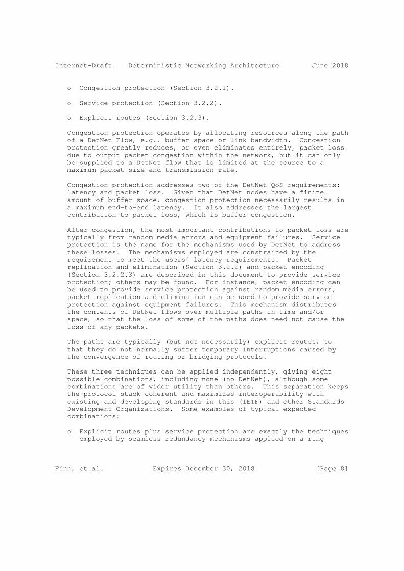
Internet-Draft Deterministic Networking Architecture June 2018
o Congestion protection (Section 3.2.1).
o Service protection (Section 3.2.2).
o Explicit routes (Section 3.2.3).
Congestion protection operates by allocating resources along the path of a DetNet Flow, e.g., buffer space or link bandwidth. Congestion protection greatly reduces, or even eliminates entirely, packet loss due to output packet congestion within the network, but it can only be supplied to a DetNet flow that is limited at the source to a maximum packet size and transmission rate.
Congestion protection addresses two of the DetNet QoS requirements: latency and packet loss. Given that DetNet nodes have a finite amount of buffer space, congestion protection necessarily results in a maximum end-to-end latency. It also addresses the largest contribution to packet loss, which is buffer congestion.
After congestion, the most important contributions to packet loss are typically from random media errors and equipment failures. Service protection is the name for the mechanisms used by DetNet to address these losses. The mechanisms employed are constrained by the requirement to meet the users’ latency requirements. Packet replication and elimination (Section 3.2.2) and packet encoding (Section 3.2.2.3) are described in this document to provide service protection; others may be found. For instance, packet encoding can be used to provide service protection against random media errors, packet replication and elimination can be used to provide service protection against equipment failures. This mechanism distributes the contents of DetNet flows over multiple paths in time and/or space, so that the loss of some of the paths does need not cause the loss of any packets.
The paths are typically (but not necessarily) explicit routes, so that they do not normally suffer temporary interruptions caused by the convergence of routing or bridging protocols.
These three techniques can be applied independently, giving eight possible combinations, including none (no DetNet), although some combinations are of wider utility than others. This separation keeps the protocol stack coherent and maximizes interoperability with existing and developing standards in this (IETF) and other Standards Development Organizations. Some examples of typical expected combinations:
o Explicit routes plus service protection are exactly the techniques employed by seamless redundancy mechanisms applied on a ring
Finn, et al. Expires December 30, 2018 [Page 8]

Internet-Draft Deterministic Networking Architecture June 2018
topology as described, e.g., in [IEEE802.1CB]. In this case, explicit routes are achieved by limiting the physical topology of the network to a ring. Sequentialization, replication, and duplicate elimination are facilitated by packet tags added at the front or the end of Ethernet frames.
o Congestion protection alone is offered by IEEE 802.1 Audio Video bridging [IEEE802.1BA]. As long as the network suffers no failures, zero congestion loss can be achieved through the use of a reservation protocol (MSRP [IEEE802.1Q]), shapers in every bridge, and proper dimensioning.
o Using all three together gives maximum protection.
There are, of course, simpler methods available (and employed, today) to achieve levels of latency and packet loss that are satisfactory for many applications. Prioritization and over-provisioning is one such technique. However, these methods generally work best in the absence of any significant amount of non-critical traffic in the network (if, indeed, such traffic is supported at all), or work only if the critical traffic constitutes only a small portion of the network’s theoretical capacity, or work only if all systems are functioning properly, or in the absence of actions by end systems that disrupt the network’s operations.
There are any number of methods in use, defined, or in progress for accomplishing each of the above techniques. It is expected that this DetNet Architecture will assist various vendors, users, and/or "vertical" Standards Development Organizations (dedicated to a single industry) to make selections among the available means of implementing DetNet networks.
3.2. Mechanisms to achieve DetNet QoS
3.2.1. Congestion protection
3.2.1.1. Eliminate congestion loss
The primary means by which DetNet achieves its QoS assurances is to reduce, or even completely eliminate, congestion within a node as a cause of packet loss. Given that a DetNet flow cannot be throttled, this can be achieved only by the provision of sufficient buffer storage at each hop through the network to ensure that no packets are dropped due to a lack of buffer storage.
Ensuring adequate buffering requires, in turn, that the source, and every intermediate node along the path to the destination (or nearly every node, see Section 4.3.3) be careful to regulate its output to
Finn, et al. Expires December 30, 2018 [Page 9]

Internet-Draft Deterministic Networking Architecture June 2018
not exceed the data rate for any DetNet flow, except for brief periods when making up for interfering traffic. Any packet sent ahead of its time potentially adds to the number of buffers required by the next hop and may thus exceed the resources allocated for a particular DetNet flow.
The low-level mechanisms described in Section 4.5 provide the necessary regulation of transmissions by an end system or intermediate node to provide congestion protection. The allocation of the bandwidth and buffers for a DetNet flow requires provisioning A DetNet node may have other resources requiring allocation and/or scheduling, that might otherwise be over-subscribed and trigger the rejection of a reservation.
3.2.1.2. Jitter Reduction
A core objective of DetNet is to enable the convergence of sensitive non-IP networks onto a common network infrastructure. This requires the accurate emulation of currently deployed mission-specific networks, which for example rely on point-to-point analog (e.g., 4-20mA modulation) and serial-digital cables (or buses) for highly reliable, synchronized and jitter-free communications. While the latency of analog transmissions is basically the speed of light, legacy serial links are usually slow (in the order of Kbps) compared to, say, GigE, and some latency is usually acceptable. What is not acceptable is the introduction of excessive jitter, which may, for instance, affect the stability of control systems.
Applications that are designed to operate on serial links usually do not provide services to recover the jitter, because jitter simply does not exist there. DetNet flows are generally expected to be delivered in-order and the precise time of reception influences the processes. In order to converge such existing applications, there is a desire to emulate all properties of the serial cable, such as clock transportation, perfect flow isolation and fixed latency. While minimal jitter (in the form of specifying minimum, as well as maximum, end-to-end latency) is supported by DetNet, there are practical limitations on packet-based networks in this regard. In general, users are encouraged to use, instead of, "do this when you get the packet," a combination of:
o Sub-microsecond time synchronization among all source and destination end systems, and
o Time-of-execution fields in the application packets.
Jitter reduction is provided by the mechanisms described in Section 4.5 that also provide congestion protection.
Finn, et al. Expires December 30, 2018 [Page 10]

Internet-Draft Deterministic Networking Architecture June 2018
3.2.2. Service Protection
Service protection aims to mitigate or eliminate packet loss due to equipment failures, random media and/or memory faults. These types of packet loss can be greatly reduced by spreading the data over multiple disjoint forwarding paths. Various service protection methods are described in [RFC6372], e.g., 1+1 linear protection. This section describes the functional details of an additional method in Section 3.2.2.2, which can be implemented as described in Section 3.2.2.3 or as specified in [I-D.ietf-detnet-dp-sol-mpls] in order to provide 1+n hitless protection. The appropriate service protection mechanism depends on the scenario and the requirements.
3.2.2.1. In-Order Delivery
Out-of-order packet delivery can be a side effect of service protection. Packets delivered out-of-order impact the amount of buffering needed at the destination to properly process the received data. Such packets also influence the jitter of a flow. The DetNet service includes maximum allowed misordering as a constraint. Zero misordering would be a valid service constraint to reflect that the end system(s) of the flow cannot tolerate any out-of-order delivery. Service protection may provide a mechanism to support in-order delivery.
3.2.2.2. Packet Replication and Elimination
This section describes a service protection method that sends copies of the same packets over multiple paths.
The DetNet service layer includes the packet replication (PRF), the packet elimination (PEF), and the packet ordering functionality (POF) for use in DetNet edge, relay node, and end system packet processing. Either of these functions can be enabled in a DetNet edge node, relay node or end system. The collective name for all three functions is PREOF. The packet replication and elimination service protection method altogether involves four capabilities:
o Providing sequencing information to the packets of a DetNet compound flow. This may be done by adding a sequence number or time stamp as part of DetNet, or may be inherent in the packet, e.g., in a transport protocol, or associated to other physical properties such as the precise time (and radio channel) of reception of the packet. This is typically done once, at or near the source.
o The Packet Replication Function (PRF) replicates these packets into multiple DetNet member flows and typically sends them along
Finn, et al. Expires December 30, 2018 [Page 11]

Internet-Draft Deterministic Networking Architecture June 2018
multiple different paths to the destination(s), e.g., over the explicit routes of Section 3.2.3. The location within a node, and the mechanism used for the PRF is implementation specific.
o The Packet Elimination Function (PEF) eliminates duplicate packets of a DetNet flow based on the sequencing information and a history of received packets. The output of the PEF is always a single packet. This may be done at any node along the path to save network resources further downstream, in particular if multiple Replication points exist. But the most common case is to perform this operation at the very edge of the DetNet network, preferably in or near the receiver. The location within a node, and mechanism used for the PEF is implementation specific.
o The Packet Ordering Function (POF) uses the sequencing information to re-order a DetNet flow’s packets that are received out of order.
The order in which a node applies PEF, POF, and PRF to a DetNet flow is implementation specific.
Some service protection mechanisms rely on switching from one flow to another when a failure of a flow is detected. Contrarily, packet replication and elimination combines the DetNet member flows sent along multiple different paths, and performs a packet-by-packet selection of which to discard, e.g., based on sequencing information.
In the simplest case, this amounts to replicating each packet in a source that has two interfaces, and conveying them through the network, along separate (disjoint non-SRLG) paths, to the similarly dual-homed destinations, that discard the extras. This ensures that one path (with zero congestion loss) remains, even if some intermediate node fails. The sequencing information can also be used for loss detection and for re-ordering.
DetNet relay nodes in the network can provide replication and elimination facilities at various points in the network, so that multiple failures can be accommodated.
This is shown in Figure 1, where the two relay nodes each replicate (R) the DetNet flow on input, sending the DetNet member flows to both the other relay node and to the end system, and eliminate duplicates (E) on the output interface to the right-hand end system. Any one link in the network can fail, and the DetNet compound flow can still get through. Furthermore, two links can fail, as long as they are in different segments of the network.
Finn, et al. Expires December 30, 2018 [Page 12]

Internet-Draft Deterministic Networking Architecture June 2018
> > > > > > > > > relay > > > > > > > > > /------------+ R node E +------------\ > > / v + ^ \ > end R + v | ^ + E end system + v | ^ + system > \ v + ^ / > > \------------+ R relay E +-----------/ > > > > > > > > > > node > > > > > > > >
Figure 1: Packet replication and elimination
Packet replication and elimination does not react to and correct failures; it is entirely passive. Thus, intermittent failures, mistakenly created packet filters, or misrouted data is handled just the same as the equipment failures that are handled by typical routing and bridging protocols.
If packet replication and elimination is used over paths providing congestion protection (Section 3.2.1), and member flows that take different-length paths through the network are combined, a merge point may require extra buffering to equalize the delays over the different paths. This equalization ensures that the resultant compound flow will not exceed its contracted bandwidth even after one or the other of the paths is restored after a failure. The extra buffering can be also used to provide in-order delivery.
3.2.2.3. Packet encoding for service protection
There are methods for using multiple paths to provide service protection that involve encoding the information in a packet belonging to a DetNet flow into multiple transmission units, combining information from multiple packets into any given transmission unit. Such techniques, also known as "network coding", can be used as a DetNet service protection technique.
3.2.3. Explicit routes
In networks controlled by typical dynamic control protocols such as IS-IS or OSPF, a network topology event in one part of the network can impact, at least briefly, the delivery of data in parts of the network remote from the failure or recovery event. Even the use of redundant paths through a network defined, e.g., by [RFC6372] do not eliminate the chances of packet loss. Furthermore, out-of-order packet delivery can be a side effect of route changes.
Many real-time networks rely on physical rings or chains of two-port devices, with a relatively simple ring control protocol. This supports redundant paths for service protection with a minimum of
Finn, et al. Expires December 30, 2018 [Page 13]

Internet-Draft Deterministic Networking Architecture June 2018
wiring. As an additional benefit, ring topologies can often utilize different topology management protocols than those used for a mesh network, with a consequent reduction in the response time to topology changes. Of course, this comes at some cost in terms of increased hop count, and thus latency, for the typical path.
In order to get the advantages of low hop count and still ensure against even very brief losses of connectivity, DetNet employs explicit routes, where the path taken by a given DetNet flow does not change, at least immediately, and likely not at all, in response to network topology events. Service protection (Section 3.2.2 or Section 3.2.2.3) over explicit routes provides a high likelihood of continuous connectivity. Explicit routes can be established various ways, e.g., with RSVP-TE [RFC3209], with Segment Routing (SR) [I-D.ietf-spring-segment-routing], via a Software Defined Networking approach [RFC7426], with IS-IS [RFC7813], etc. Explicit routes are typically used in MPLS TE LSPs.
Out-of-order packet delivery can be a side effect of distributing a single flow over multiple paths especially when there is a change from one path to another when combining the flow. This is irrespective of the distribution method used, also applies to service protection over explicit routes. As described in Section 3.2.2.1, out-of-order packets influence the jitter of a flow and impact the amount of buffering needed to process the data; therefore, DetNet service includes maximum allowed misordering as a constraint. The use of explicit routes helps to provide in-order delivery because there is no immediate route change with the network topology, but the changes are plannable as they are between the different explicit routes.
3.3. Secondary goals for DetNet
Many applications require DetNet to provide additional services, including coexistence with other QoS mechanisms Section 3.3.1 and protection against misbehaving transmitters Section 3.3.2.
3.3.1. Coexistence with normal traffic
A DetNet network supports the dedication of a high proportion (e.g. 75%) of the network bandwidth to DetNet flows. But, no matter how much is dedicated for DetNet flows, it is a goal of DetNet to coexist with existing Class of Service schemes (e.g., DiffServ). It is also important that non-DetNet traffic not disrupt the DetNet flow, of course (see Section 3.3.2 and Section 5). For these reasons:
Finn, et al. Expires December 30, 2018 [Page 14]

Internet-Draft Deterministic Networking Architecture June 2018
o Bandwidth (transmission opportunities) not utilized by a DetNet flow are available to non-DetNet packets (though not to other DetNet flows).
o DetNet flows can be shaped or scheduled, in order to ensure that the highest-priority non-DetNet packet is also ensured a worst- case latency (at any given hop).
o When transmission opportunities for DetNet flows are scheduled in detail, then the algorithm constructing the schedule should leave sufficient opportunities for non-DetNet packets to satisfy the needs of the users of the network. Detailed scheduling can also permit the time-shared use of buffer resources by different DetNet flows.
Ideally, the net effect of the presence of DetNet flows in a network on the non-DetNet packets is primarily a reduction in the available bandwidth.
3.3.2. Fault Mitigation
One key to building robust real-time systems is to reduce the infinite variety of possible failures to a number that can be analyzed with reasonable confidence. DetNet aids in the process by allowing for filters and policers to detect DetNet packets received on the wrong interface, or at the wrong time, or in too great a volume, and to then take actions such as discarding the offending packet, shutting down the offending DetNet flow, or shutting down the offending interface.
It is also essential that filters and service remarking be employed at the network edge to prevent non-DetNet packets from being mistaken for DetNet packets, and thus impinging on the resources allocated to DetNet packets.
There exist techniques, at present and/or in various stages of standardization, that can perform these fault mitigation tasks that deliver a high probability that misbehaving systems will have zero impact on well-behaved DetNet flows, except of course, for the receiving interface(s) immediately downstream of the misbehaving device. Examples of such techniques include traffic policing functions (e.g. [RFC2475]) and separating flows into per-flow rate- limited queues.
Finn, et al. Expires December 30, 2018 [Page 15]

Internet-Draft Deterministic Networking Architecture June 2018
4. DetNet Architecture
4.1. DetNet stack model
4.1.1. Representative Protocol Stack Model
Figure 2 illustrates a conceptual DetNet data plane layering model. One may compare it to that in [IEEE802.1CB], Annex C.
| packets going | ^ packets coming ^ v down the stack v | up the stack | +----------------------+ +-----------------------+ | Source | | Destination | +----------------------+ +-----------------------+ | Service layer: | | Service layer: | | Packet sequencing | | Duplicate elimination | | Flow replication | | Flow merging | | Packet encoding | | Packet decoding | +----------------------+ +-----------------------+ | Transport layer: | | Transport layer: | | Congestion prot. | | Congestion prot. | | Explicit routes | | Explicit routes | +----------------------+ +-----------------------+ | Lower layers | | Lower layers | +----------------------+ +-----------------------+ v ^ \_________________________/
Figure 2: DetNet data plane protocol stack
Not all layers are required for any given application, or even for any given network. The functionality shown in Figure 2 is:
Application Shown as "source" and "destination" in the diagram.
Packet sequencing As part of DetNet service protection, supplies the sequence number for packet replication and elimination (Section 3.2.2). Peers with Duplicate elimination. This layer is not needed if a higher-layer transport protocol is expected to perform any packet sequencing and duplicate elimination required by the DetNet flow replication.
Duplicate elimination As part of the DetNet service layer, based on the sequenced number supplied by its peer, packet sequencing, Duplicate elimination discards any duplicate packets generated by
Finn, et al. Expires December 30, 2018 [Page 16]

Internet-Draft Deterministic Networking Architecture June 2018
DetNet flow replication. It can operate on member flows, compound flows, or both. The replication may also be inferred from other information such as the precise time of reception in a scheduled network. The duplicate elimination layer may also perform resequencing of packets to restore packet order in a flow that was disrupted by the loss of packets on one or another of the multiple paths taken.
Flow replication As part of DetNet service protection, packets that belong to a DetNet compound flow are replicated into two or more DetNet member flows. This function is separate from packet sequencing. Flow replication can be an explicit replication and remarking of packets, or can be performed by, for example, techniques similar to ordinary multicast replication, albeit with resource allocation implications. Peers with DetNet flow merging.
Flow merging As part of DetNet service protection, merges DetNet member flows together for packets coming up the stack belonging to a specific DetNet compound flow. Peers with DetNet flow replication. DetNet flow merging, together with packet sequencing, duplicate elimination, and DetNet flow replication perform packet replication and elimination (Section 3.2.2).
Packet encoding As part of DetNet service protection, as an alternative to packet sequencing and flow replication, packet encoding combines the information in multiple DetNet packets, perhaps from different DetNet compound flows, and transmits that information in packets on different DetNet member Flows. Peers with Packet decoding.
Packet decoding As part of DetNet service protection, as an alternative to flow merging and duplicate elimination, packet decoding takes packets from different DetNet member flows, and computes from those packets the original DetNet packets from the compound flows input to packet encoding. Peers with Packet encoding.
Congestion protection The DetNet transport layer provides congestion protection. See Section 4.5. The actual queuing and shaping mechanisms are typically provided by underlying subnet layers, these can be closely associated with the means of providing paths for
Finn, et al. Expires December 30, 2018 [Page 17]
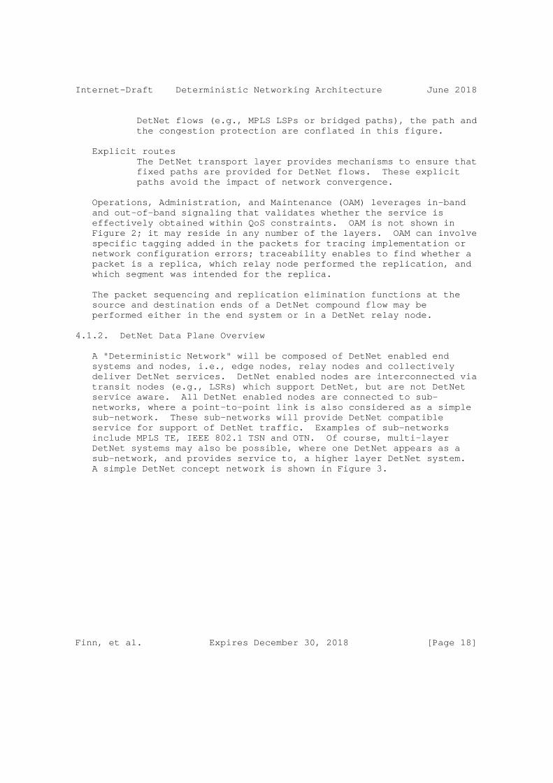
Internet-Draft Deterministic Networking Architecture June 2018
DetNet flows (e.g., MPLS LSPs or bridged paths), the path and the congestion protection are conflated in this figure.
Explicit routes The DetNet transport layer provides mechanisms to ensure that fixed paths are provided for DetNet flows. These explicit paths avoid the impact of network convergence.
Operations, Administration, and Maintenance (OAM) leverages in-band and out-of-band signaling that validates whether the service is effectively obtained within QoS constraints. OAM is not shown in Figure 2; it may reside in any number of the layers. OAM can involve specific tagging added in the packets for tracing implementation or network configuration errors; traceability enables to find whether a packet is a replica, which relay node performed the replication, and which segment was intended for the replica.
The packet sequencing and replication elimination functions at the source and destination ends of a DetNet compound flow may be performed either in the end system or in a DetNet relay node.
4.1.2. DetNet Data Plane Overview
A "Deterministic Network" will be composed of DetNet enabled end systems and nodes, i.e., edge nodes, relay nodes and collectively deliver DetNet services. DetNet enabled nodes are interconnected via transit nodes (e.g., LSRs) which support DetNet, but are not DetNet service aware. All DetNet enabled nodes are connected to sub- networks, where a point-to-point link is also considered as a simple sub-network. These sub-networks will provide DetNet compatible service for support of DetNet traffic. Examples of sub-networks include MPLS TE, IEEE 802.1 TSN and OTN. Of course, multi-layer DetNet systems may also be possible, where one DetNet appears as a sub-network, and provides service to, a higher layer DetNet system. A simple DetNet concept network is shown in Figure 3.
Finn, et al. Expires December 30, 2018 [Page 18]

Internet-Draft Deterministic Networking Architecture June 2018
TSN Edge Transit Relay DetNet End System Node Node Node End System
+---------+ +.........+ +---------+ | Appl. |<--:Svc Proxy:-- End to End Service ---------->| Appl. | +---------+ +---------+ +---------+ +---------+ | TSN | |TSN| |Svc|<-- DetNet flow ---: Service :-->| Service | +---------+ +---+ +---+ +---------+ +---------+ +---------+ |Transport| |Trp| |Trp| |Transport| |Trp| |Trp| |Transport| +-------.-+ +-.-+ +-.-+ +--.----.-+ +-.-+ +-.-+ +---.-----+ : Link : / ,-----. \ : Link : / ,-----. \ +.......+ +-[ Sub ]-+ +........+ +-[ Sub ]-+ [Network] [Network] ‘-----’ ‘-----’
Figure 3: A Simple DetNet Enabled Network
Distinguishing the function of two DetNet data plane layers, the DetNet service layer and the DetNet transport layer, helps to explore and evaluate various combinations of the data plane solutions available, some are illustrated in Figure 4. This separation of DetNet layers, while helpful, should not be considered as formal requirement. For example, some technologies may violate these strict layers and still be able to deliver a DetNet service.
. . +-----------+ | Service | PW, UDP, GRE +-----------+ | Transport | IPv6, IPv4, MPLS TE LSPs, MPLS SR +-----------+ . .
Figure 4: DetNet adaptation to data plane
In some networking scenarios, the end system initially provides a DetNet flow encapsulation, which contains all information needed by DetNet nodes (e.g., Real-time Transport Protocol (RTP) [RFC3550] based DetNet flow transported over a native UDP/IP network or PseudoWire). In other scenarios, the encapsulation formats might differ significantly.
There are many valid options to create a data plane solution for DetNet traffic by selecting a technology approach for the DetNet service layer and also selecting a technology approach for the DetNet transport layer. There are a high number of valid combinations.
Finn, et al. Expires December 30, 2018 [Page 19]
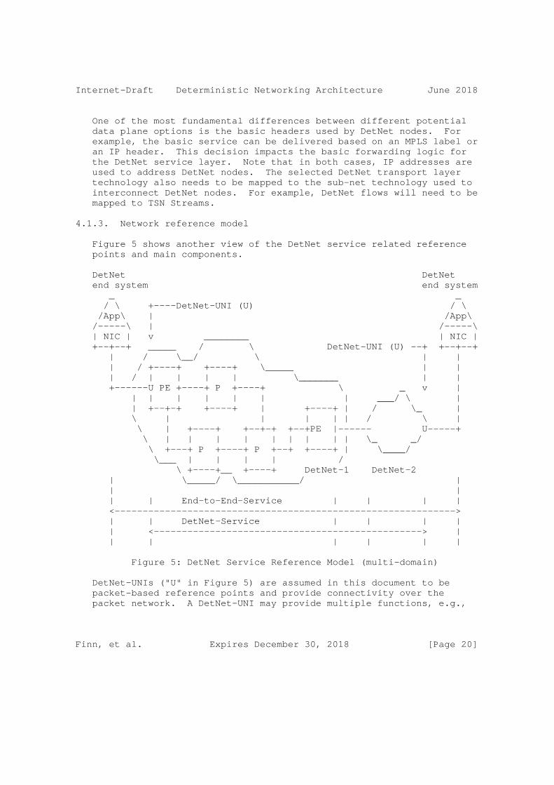
Internet-Draft Deterministic Networking Architecture June 2018
One of the most fundamental differences between different potential data plane options is the basic headers used by DetNet nodes. For example, the basic service can be delivered based on an MPLS label or an IP header. This decision impacts the basic forwarding logic for the DetNet service layer. Note that in both cases, IP addresses are used to address DetNet nodes. The selected DetNet transport layer technology also needs to be mapped to the sub-net technology used to interconnect DetNet nodes. For example, DetNet flows will need to be mapped to TSN Streams.
4.1.3. Network reference model
Figure 5 shows another view of the DetNet service related reference points and main components.
DetNet DetNet end system end system _ _ / \ +----DetNet-UNI (U) / \ /App\ | /App\ /-----\ | /-----\ | NIC | v ________ | NIC | +--+--+ _____ / \ DetNet-UNI (U) --+ +--+--+ | / \__/ \ | | | / +----+ +----+ \_____ | | | / | | | | \_______ | | +------U PE +----+ P +----+ \ _ v | | | | | | | | ___/ \ | | +--+-+ +----+ | +----+ | / \_ | \ | | | | | / \ | \ | +----+ +--+-+ +--+PE |------ U-----+ \ | | | | | | | | | \_ _/ \ +---+ P +----+ P +--+ +----+ | \____/ \___ | | | | / \ +----+__ +----+ DetNet-1 DetNet-2 | \_____/ \___________/ | | | | | End-to-End-Service | | | | <-------------------------------------------------------------> | | DetNet-Service | | | | | <------------------------------------------------> | | | | | | |
Figure 5: DetNet Service Reference Model (multi-domain)
DetNet-UNIs ("U" in Figure 5) are assumed in this document to be packet-based reference points and provide connectivity over the packet network. A DetNet-UNI may provide multiple functions, e.g.,
Finn, et al. Expires December 30, 2018 [Page 20]

Internet-Draft Deterministic Networking Architecture June 2018
it may add networking technology specific encapsulation to the DetNet flows if necessary; it may provide status of the availability of the resources associated with a reservation; it may provide a synchronization service for the end system; it may carry enough signaling to place the reservation in a network without a controller, or if the controller only deals with the network but not the end systems. Internal reference points of end systems (between the application and the NIC) are more challenging from control perspective and they may have extra requirements (e.g., in-order delivery is expected in end system internal reference points, whereas it is considered optional over the DetNet-UNI).
4.2. DetNet systems
4.2.1. End system
The native data flow between the source/destination end systems is referred to as application-flow (App-flow). The traffic characteristics of an App-flow can be CBR (constant bit rate) or VBR (variable bit rate) and can have L1 or L2 or L3 encapsulation (e.g., TDM (time-division multiplexing), Ethernet, IP). These characteristics are considered as input for resource reservation and might be simplified to ensure determinism during transport (e.g., making reservations for the peak rate of VBR traffic, etc.).
An end system may or may not be DetNet transport layer aware or DetNet service layer aware. That is, an end system may or may not contain DetNet specific functionality. End systems with DetNet functionalities may have the same or different transport layer as the connected DetNet domain. Categorization of end systems are shown in Figure 6.
Finn, et al. Expires December 30, 2018 [Page 21]
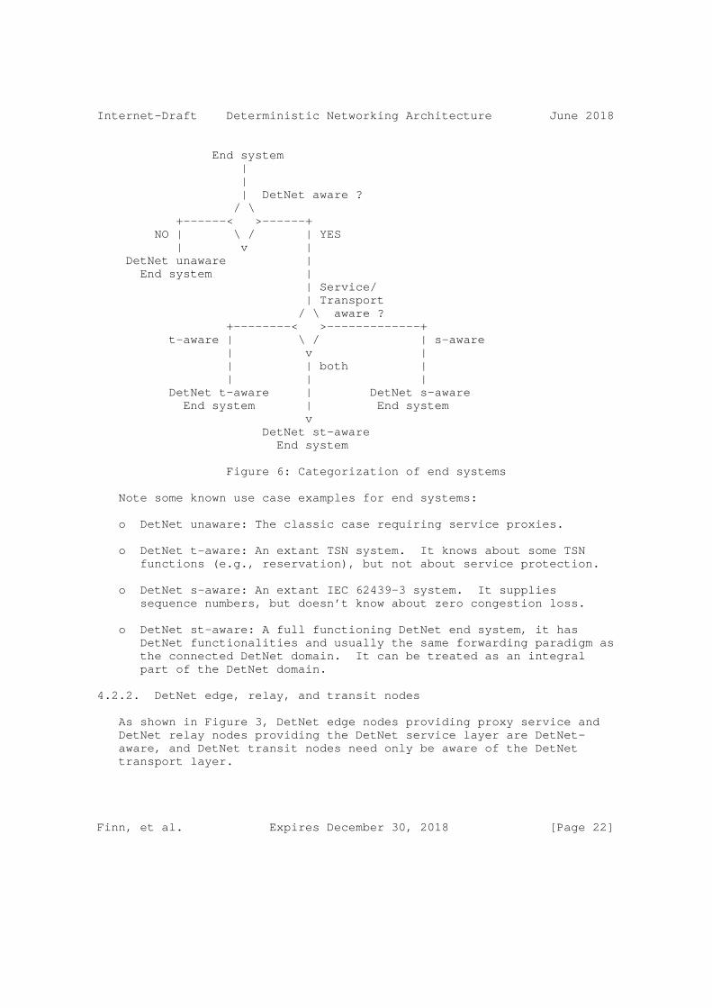
Internet-Draft Deterministic Networking Architecture June 2018
End system | | | DetNet aware ? / \ +------< >------+ NO | \ / | YES | v | DetNet unaware | End system | | Service/ | Transport / \ aware ? +--------< >-------------+ t-aware | \ / | s-aware | v | | | both | | | | DetNet t-aware | DetNet s-aware End system | End system v DetNet st-aware End system
Figure 6: Categorization of end systems
Note some known use case examples for end systems:
o DetNet unaware: The classic case requiring service proxies.
o DetNet t-aware: An extant TSN system. It knows about some TSN functions (e.g., reservation), but not about service protection.
o DetNet s-aware: An extant IEC 62439-3 system. It supplies sequence numbers, but doesn’t know about zero congestion loss.
o DetNet st-aware: A full functioning DetNet end system, it has DetNet functionalities and usually the same forwarding paradigm as the connected DetNet domain. It can be treated as an integral part of the DetNet domain.
4.2.2. DetNet edge, relay, and transit nodes
As shown in Figure 3, DetNet edge nodes providing proxy service and DetNet relay nodes providing the DetNet service layer are DetNet- aware, and DetNet transit nodes need only be aware of the DetNet transport layer.
Finn, et al. Expires December 30, 2018 [Page 22]
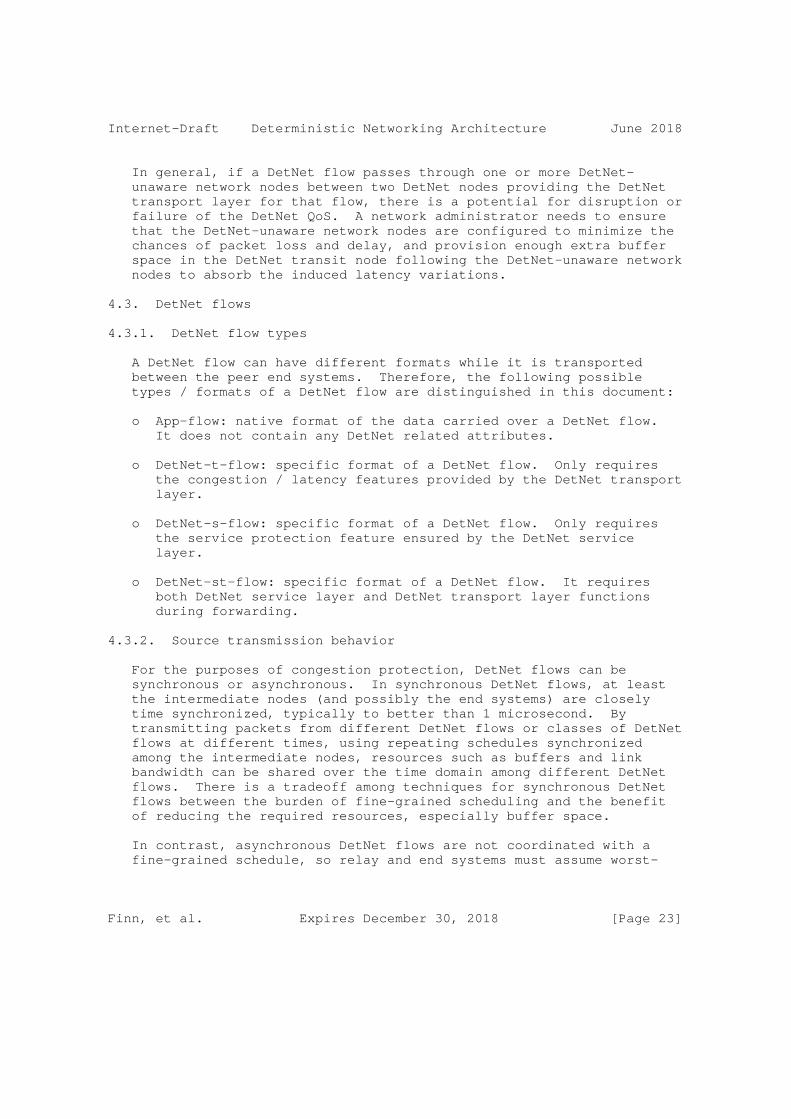
Internet-Draft Deterministic Networking Architecture June 2018
In general, if a DetNet flow passes through one or more DetNet- unaware network nodes between two DetNet nodes providing the DetNet transport layer for that flow, there is a potential for disruption or failure of the DetNet QoS. A network administrator needs to ensure that the DetNet-unaware network nodes are configured to minimize the chances of packet loss and delay, and provision enough extra buffer space in the DetNet transit node following the DetNet-unaware network nodes to absorb the induced latency variations.
4.3. DetNet flows
4.3.1. DetNet flow types
A DetNet flow can have different formats while it is transported between the peer end systems. Therefore, the following possible types / formats of a DetNet flow are distinguished in this document:
o App-flow: native format of the data carried over a DetNet flow. It does not contain any DetNet related attributes.
o DetNet-t-flow: specific format of a DetNet flow. Only requires the congestion / latency features provided by the DetNet transport layer.
o DetNet-s-flow: specific format of a DetNet flow. Only requires the service protection feature ensured by the DetNet service layer.
o DetNet-st-flow: specific format of a DetNet flow. It requires both DetNet service layer and DetNet transport layer functions during forwarding.
4.3.2. Source transmission behavior
For the purposes of congestion protection, DetNet flows can be synchronous or asynchronous. In synchronous DetNet flows, at least the intermediate nodes (and possibly the end systems) are closely time synchronized, typically to better than 1 microsecond. By transmitting packets from different DetNet flows or classes of DetNet flows at different times, using repeating schedules synchronized among the intermediate nodes, resources such as buffers and link bandwidth can be shared over the time domain among different DetNet flows. There is a tradeoff among techniques for synchronous DetNet flows between the burden of fine-grained scheduling and the benefit of reducing the required resources, especially buffer space.
In contrast, asynchronous DetNet flows are not coordinated with a fine-grained schedule, so relay and end systems must assume worst-
Finn, et al. Expires December 30, 2018 [Page 23]
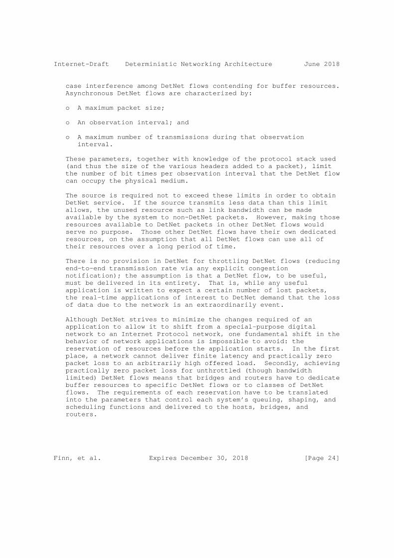
Internet-Draft Deterministic Networking Architecture June 2018
case interference among DetNet flows contending for buffer resources. Asynchronous DetNet flows are characterized by:
o A maximum packet size;
o An observation interval; and
o A maximum number of transmissions during that observation interval.
These parameters, together with knowledge of the protocol stack used (and thus the size of the various headers added to a packet), limit the number of bit times per observation interval that the DetNet flow can occupy the physical medium.
The source is required not to exceed these limits in order to obtain DetNet service. If the source transmits less data than this limit allows, the unused resource such as link bandwidth can be made available by the system to non-DetNet packets. However, making those resources available to DetNet packets in other DetNet flows would serve no purpose. Those other DetNet flows have their own dedicated resources, on the assumption that all DetNet flows can use all of their resources over a long period of time.
There is no provision in DetNet for throttling DetNet flows (reducing end-to-end transmission rate via any explicit congestion notification); the assumption is that a DetNet flow, to be useful, must be delivered in its entirety. That is, while any useful application is written to expect a certain number of lost packets, the real-time applications of interest to DetNet demand that the loss of data due to the network is an extraordinarily event.
Although DetNet strives to minimize the changes required of an application to allow it to shift from a special-purpose digital network to an Internet Protocol network, one fundamental shift in the behavior of network applications is impossible to avoid: the reservation of resources before the application starts. In the first place, a network cannot deliver finite latency and practically zero packet loss to an arbitrarily high offered load. Secondly, achieving practically zero packet loss for unthrottled (though bandwidth limited) DetNet flows means that bridges and routers have to dedicate buffer resources to specific DetNet flows or to classes of DetNet flows. The requirements of each reservation have to be translated into the parameters that control each system’s queuing, shaping, and scheduling functions and delivered to the hosts, bridges, and routers.
Finn, et al. Expires December 30, 2018 [Page 24]
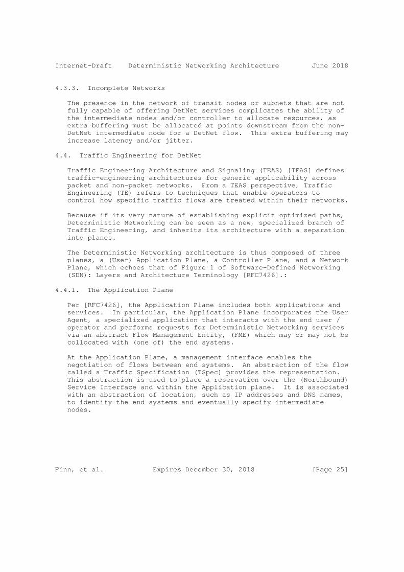
Internet-Draft Deterministic Networking Architecture June 2018
4.3.3. Incomplete Networks
The presence in the network of transit nodes or subnets that are not fully capable of offering DetNet services complicates the ability of the intermediate nodes and/or controller to allocate resources, as extra buffering must be allocated at points downstream from the non- DetNet intermediate node for a DetNet flow. This extra buffering may increase latency and/or jitter.
4.4. Traffic Engineering for DetNet
Traffic Engineering Architecture and Signaling (TEAS) [TEAS] defines traffic-engineering architectures for generic applicability across packet and non-packet networks. From a TEAS perspective, Traffic Engineering (TE) refers to techniques that enable operators to control how specific traffic flows are treated within their networks.
Because if its very nature of establishing explicit optimized paths, Deterministic Networking can be seen as a new, specialized branch of Traffic Engineering, and inherits its architecture with a separation into planes.
The Deterministic Networking architecture is thus composed of three planes, a (User) Application Plane, a Controller Plane, and a Network Plane, which echoes that of Figure 1 of Software-Defined Networking (SDN): Layers and Architecture Terminology [RFC7426].:
4.4.1. The Application Plane
Per [RFC7426], the Application Plane includes both applications and services. In particular, the Application Plane incorporates the User Agent, a specialized application that interacts with the end user / operator and performs requests for Deterministic Networking services via an abstract Flow Management Entity, (FME) which may or may not be collocated with (one of) the end systems.
At the Application Plane, a management interface enables the negotiation of flows between end systems. An abstraction of the flow called a Traffic Specification (TSpec) provides the representation. This abstraction is used to place a reservation over the (Northbound) Service Interface and within the Application plane. It is associated with an abstraction of location, such as IP addresses and DNS names, to identify the end systems and eventually specify intermediate nodes.
Finn, et al. Expires December 30, 2018 [Page 25]

Internet-Draft Deterministic Networking Architecture June 2018
4.4.2. The Controller Plane
The Controller Plane corresponds to the aggregation of the Control and Management Planes in [RFC7426], though Common Control and Measurement Plane (CCAMP) [CCAMP] makes an additional distinction between management and measurement. When the logical separation of the Control, Measurement and other Management entities is not relevant, the term Controller Plane is used for simplicity to represent them all, and the term controller plane entity (CPE) refers to any device operating in that plane, whether is it a Path Computation entity, or a Network Management entity (NME)), or a distributed control plane. The Path Computation Element (PCE) [RFC4655] is a core element of a controller, in charge of computing Deterministic paths to be applied in the Network Plane.
A (Northbound) Service Interface enables applications in the Application Plane to communicate with the entities in the Controller Plane as illustrated in Figure 7.
One or more PCE(s) collaborate to implement the requests from the FME as Per-Flow Per-Hop Behaviors installed in the intermediate nodes for each individual flow. The PCEs place each flow along a deterministic sequence of intermediate nodes so as to respect per-flow constraints such as security and latency, and optimize the overall result for metrics such as an abstract aggregated cost. The deterministic sequence can typically be more complex than a direct sequence and include redundancy path, with one or more packet replication and elimination points.
4.4.3. The Network Plane
The Network Plane represents the network devices and protocols as a whole, regardless of the Layer at which the network devices operate. It includes Forwarding Plane (data plane), Application, and Operational Plane (control plane) aspects.
The network Plane comprises the Network Interface Cards (NIC) in the end systems, which are typically IP hosts, and intermediate nodes, which are typically IP routers and switches. Network-to-Network Interfaces such as used for Traffic Engineering path reservation in [RFC5921], as well as User-to-Network Interfaces (UNI) such as provided by the Local Management Interface (LMI) between network and end systems, are both part of the Network Plane, both in the control plane and the data plane.
A Southbound (Network) Interface enables the entities in the Controller Plane to communicate with devices in the Network Plane as
Finn, et al. Expires December 30, 2018 [Page 26]

Internet-Draft Deterministic Networking Architecture June 2018
illustrated in Figure 7. This interface leverages and extends TEAS to describe the physical topology and resources in the Network Plane.
End End System System
-+-+-+-+-+-+-+ Northbound -+-+-+-+-+-+-+-+-+-+-+-+-+-+-+-+-+-
CPE CPE CPE CPE
-+-+-+-+-+-+-+ Southbound -+-+-+-+-+-+-+-+-+-+-+-+-+-+-+-+-+-
intermediate intermed. intermed. intermed. Node Node Node Node NIC NIC intermediate intermed. intermed. intermed. Node Node Node Node
Figure 7: Northbound and Southbound interfaces
The intermediate nodes (and eventually the end systems NIC) expose their capabilities and physical resources to the controller (the CPE), and update the CPEs with their dynamic perception of the topology, across the Southbound Interface. In return, the CPEs set the per-flow paths up, providing a Flow Characterization that is more tightly coupled to the intermediate node Operation than a TSpec.
At the Network plane, intermediate nodes may exchange information regarding the state of the paths, between adjacent systems and eventually with the end systems, and forward packets within constraints associated to each flow, or, when unable to do so, perform a last resort operation such as drop or declassify.
This document focuses on the Southbound interface and the operation of the Network Plane.
4.5. Queuing, Shaping, Scheduling, and Preemption
DetNet achieves congestion protection and bounded delivery latency by reserving bandwidth and buffer resources at every hop along the path of the DetNet flow. The reservation itself is not sufficient, however. Implementors and users of a number of proprietary and standard real-time networks have found that standards for specific data plane techniques are required to enable these assurances to be made in a multi-vendor network. The fundamental reason is that latency variation in one system results in the need for extra buffer space in the next-hop system(s), which in turn, increases the worst- case per-hop latency.
Finn, et al. Expires December 30, 2018 [Page 27]

Internet-Draft Deterministic Networking Architecture June 2018
Standard queuing and transmission selection algorithms allow a central controller to compute the latency contribution of each transit node to the end-to-end latency, to compute the amount of buffer space required in each transit node for each incremental DetNet flow, and most importantly, to translate from a flow specification to a set of values for the managed objects that control each relay or end system. For example, the IEEE 802.1 WG has specified (and is specifying) a set of queuing, shaping, and scheduling algorithms that enable each transit node (bridge or router), and/or a central controller, to compute these values. These algorithms include:
o A credit-based shaper [IEEE802.1Q] Clause 34.
o Time-gated queues governed by a rotating time schedule, synchronized among all transit nodes [IEEE802.1Qbv].
o Synchronized double (or triple) buffers driven by synchronized time ticks. [IEEE802.1Qch].
o Pre-emption of an Ethernet packet in transmission by a packet with a more stringent latency requirement, followed by the resumption of the preempted packet [IEEE802.1Qbu], [IEEE802.3br].
While these techniques are currently embedded in Ethernet [IEEE802.3] and bridging standards, we can note that they are all, except perhaps for packet preemption, equally applicable to other media than Ethernet, and to routers as well as bridges. Other media may have its own methods, see, e.g., [I-D.ietf-6tisch-architecture], [RFC7554]. DetNet may include such definitions in the future, or may define how these techniques can be used by DetNet nodes.
4.6. Service instance
A Service instance represents all the functions required on a node to allow the end-to-end service between the UNIs.
The DetNet network general reference model is shown in Figure 8 for a DetNet-Service scenario (i.e., between two DetNet-UNIs). In this figure, end systems ("A" and "B") are connected directly to the edge nodes of an IP/MPLS network ("PE1" and "PE2"). End systems participating in DetNet communication may require connectivity before setting up an App-flow that requires the DetNet service. Such a connectivity related service instance and the one dedicated for DetNet service share the same access. Packets belonging to a DetNet flow are selected by a filter configured on the access ("F1" and "F2"). As a result, data flow specific access ("access-A + F1" and "access-B + F2") are terminated in the flow specific service instance
Finn, et al. Expires December 30, 2018 [Page 28]

Internet-Draft Deterministic Networking Architecture June 2018
("SI-1" and "SI-2"). A tunnel is used to provide connectivity between the service instances.
The tunnel is used to transport exclusively the packets of the DetNet flow between "SI-1" and "SI-2". The service instances are configured to implement DetNet functions and a flow specific DetNet transport. The service instance and the tunnel may or may not be shared by multiple DetNet flows. Sharing the service instance by multiple DetNet flows requires properly populated forwarding tables of the service instance.
access-A access-B <-----> <-------- tunnel ----------> <----->
+---------+ ___ _ +---------+ End system | +----+ | / \/ \_ | +----+ | End system "A" -------F1+ | | / \ | | +F2----- "B" | | +========+ IP/MPLS +=======+ | | | |SI-1| | \__ Net._/ | |SI-2| | | +----+ | \____/ | +----+ | |PE1 | | PE2| +---------+ +---------+
Figure 8: DetNet network general reference model
The tunnel between the service instances may have some special characteristics. For example, in case of a DetNet L3 service, there are differences in the usage of the PW for DetNet traffic compared to the network model described in [RFC6658]. In the DetNet scenario, the PW is likely to be used exclusively by the DetNet flow, whereas [RFC6658] states: "The packet PW appears as a single point-to-point link to the client layer. Network-layer adjacency formation and maintenance between the client equipment will follow the normal practice needed to support the required relationship in the client layer ... This packet pseudowire is used to transport all of the required Layer-2 and Layer-3 protocols between LSR1 and LSR2". Further details are network technology specific and can be found in [I-D.ietf-detnet-dp-sol-mpls] and [I-D.ietf-detnet-dp-sol-ip].
4.7. Flow identification at technology borders
4.7.1. Exporting flow identification
A DetNet node may need to map specific flows to lower layer flows (or Streams) in order to provide specific queuing and shaping services for specific flows. For example:
Finn, et al. Expires December 30, 2018 [Page 29]

Internet-Draft Deterministic Networking Architecture June 2018
o A non-IP, strictly L2 source end system X may be sending multiple flows to the same L2 destination end system Y. Those flows may include DetNet flows with different QoS requirements, and may include non-DetNet flows.
o A router may be sending any number of flows to another router. Again, those flows may include DetNet flows with different QoS requirements, and may include non-DetNet flows.
o Two routers may be separated by bridges. For these bridges to perform any required per-flow queuing and shaping, they must be able to identify the individual flows.
o A Label Edge Router (LER) may have a Label Switched Path (LSP) set up for handling traffic destined for a particular IP address carrying only non-DetNet flows. If a DetNet flow to that same address is requested, a separate LSP may be needed, in order that all of the Label Switch Routers (LSRs) along the path to the destination give that flow special queuing and shaping.
The need for a lower-layer node to be aware of individual higher- layer flows is not unique to DetNet. But, given the endless complexity of layering and relayering over tunnels that is available to network designers, DetNet needs to provide a model for flow identification that is better than packet inspection. That is not to say that packet inspection to layer 4 or 5 addresses will not be used, or the capability standardized; but, there are alternatives.
A DetNet relay node can connect DetNet flows on different paths using different flow identification methods. For example:
o A single unicast DetNet flow passing from router A through a bridged network to router B may be assigned a TSN Stream identifier that is unique within that bridged network. The bridges can then identify the flow without accessing higher-layer headers. Of course, the receiving router must recognize and accept that TSN Stream.
o A DetNet flow passing from LSR A to LSR B may be assigned a different label than that used for other flows to the same IP destination.
In any of the above cases, it is possible that an existing DetNet flow can be an aggregate carrying multiple other DetNet flows. (Not to be confused with DetNet compound vs. member flows.) Of course, this requires that the aggregate DetNet flow be provisioned properly to carry the aggregated flows.
Finn, et al. Expires December 30, 2018 [Page 30]

Internet-Draft Deterministic Networking Architecture June 2018
Thus, rather than packet inspection, there is the option to export higher-layer information to the lower layer. The requirement to support one or the other method for flow identification (or both) is a complexity that is part of DetNet control models.
4.7.2. Flow attribute mapping between layers
Transport of DetNet flows over multiple technology domains may require that lower layers are aware of specific flows of higher layers. Such an "exporting of flow identification" is needed each time when the forwarding paradigm is changed on the transport path (e.g., two LSRs are interconnected by a L2 bridged domain, etc.). The three representative forwarding methods considered for deterministic networking are:
o IP routing
o MPLS label switching
o Ethernet bridging
A packet with corresponding Flow-IDs is illustrated in Figure 9.
add/remove add/remove Eth Flow-ID IP Flow-ID | | v v +-----------------------------------------------------------+ | | | | | | Eth | MPLS | IP | Application data | | | | | | +-----------------------------------------------------------+ ^ | add/remove MPLS Flow-ID
Figure 9: Packet with multiple Flow-IDs
The additional (domain specific) Flow-ID can be
o created by a domain specific function or
o derived from the Flow-ID added to the App-flow.
The Flow-ID must be unique inside a given domain. Note that the Flow-ID added to the App-flow is still present in the packet, but
Finn, et al. Expires December 30, 2018 [Page 31]

Internet-Draft Deterministic Networking Architecture June 2018
transport nodes may lack the function to recognize it; that’s why the additional Flow-ID is added.
4.7.3. Flow-ID mapping examples
IP nodes and MPLS nodes are assumed to be configured to push such an additional (domain specific) Flow-ID when sending traffic to an Ethernet switch (as shown in the examples below).
Figure 10 shows a scenario where an IP end system ("IP-A") is connected via two Ethernet switches ("ETH-n") to an IP router ("IP- 1").
IP domain <-----------------------------------------------
+======+ +======+ |L3-ID | |L3-ID | +======+ /\ +-----+ +======+ / \ Forward as | | /IP-A\ per ETH-ID |IP-1 | Recognize Push ------> +-+----+ | +---+-+ <----- ETH-ID ETH-ID | +----+-----+ | | v v | | +-----+ +-----+ | +------+ | | +---------+ +......+ |ETH-1+----+ETH-2| +======+ .L3-ID . +-----+ +-----+ |L3-ID | +======+ +......+ +======+ |ETH-ID| .L3-ID . |ETH-ID| +======+ +======+ +------+ |ETH-ID| +======+
Ethernet domain <---------------->
Figure 10: IP nodes interconnected by an Ethernet domain
End system "IP-A" uses the original App-flow specific ID ("L3-ID"), but as it is connected to an Ethernet domain it has to push an Ethernet-domain specific flow-ID ("VID + multicast MAC address", referred as "ETH-ID") before sending the packet to "ETH-1" node. Ethernet switch "ETH-1" can recognize the data flow based on the "ETH-ID" and it does forwarding toward "ETH-2". "ETH-2" switches the packet toward the IP router. "IP-1" must be configured to receive the Ethernet Flow-ID specific multicast flow, but (as it is an L3
Finn, et al. Expires December 30, 2018 [Page 32]

Internet-Draft Deterministic Networking Architecture June 2018
node) it decodes the data flow ID based on the "L3-ID" fields of the received packet.
Figure 11 shows a scenario where MPLS domain nodes ("PE-n" and "P-m") are connected via two Ethernet switches ("ETH-n").
MPLS domain <----------------------------------------------->
+=======+ +=======+ |MPLS-ID| |MPLS-ID| +=======+ +-----+ +-----+ +=======+ +-----+ | | Forward as | | | | |PE-1 | per ETH-ID | P-2 +-----------+ PE-2| Push -----> +-+---+ | +---+-+ +-----+ ETH-ID | +-----+----+ | \ Recognize | v v | +-- ETH-ID | +-----+ +-----+ | +---+ | | +----+ +.......+ |ETH-1+----+ETH-2| +=======+ .MPLS-ID. +-----+ +-----+ |MPLS-ID| +=======+ +=======+ |ETH-ID | +.......+ |ETH-ID | +=======+ .MPLS-ID. +-------+ +=======+ |ETH-ID | +=======+ Ethernet domain <---------------->
Figure 11: MPLS nodes interconnected by an Ethernet domain
"PE-1" uses the MPLS specific ID ("MPLS-ID"), but as it is connected to an Ethernet domain it has to push an Ethernet-domain specific flow-ID ("VID + multicast MAC address", referred as "ETH-ID") before sending the packet to "ETH-1". Ethernet switch "ETH-1" can recognize the data flow based on the "ETH-ID" and it does forwarding toward "ETH-2". "ETH-2" switches the packet toward the MPLS node ("P-2"). "P-2" must be configured to receive the Ethernet Flow-ID specific multicast flow, but (as it is an MPLS node) it decodes the data flow ID based on the "MPLS-ID" fields of the received packet.
One can appreciate from the above example that, when the means used for DetNet flow identification is altered or exported, the means for encoding the sequence number information must similarly be altered or exported.
Finn, et al. Expires December 30, 2018 [Page 33]

Internet-Draft Deterministic Networking Architecture June 2018
4.8. Advertising resources, capabilities and adjacencies
There are three classes of information that a central controller or distributed control plane needs to know that can only be obtained from the end systems and/or nodes in the network. When using a peer- to-peer control plane, some of this information may be required by a system’s neighbors in the network.
o Details of the system’s capabilities that are required in order to accurately allocate that system’s resources, as well as other systems’ resources. This includes, for example, which specific queuing and shaping algorithms are implemented (Section 4.5), the number of buffers dedicated for DetNet allocation, and the worst- case forwarding delay and misordering.
o The dynamic state of a node’s DetNet resources.
o The identity of the system’s neighbors, and the characteristics of the link(s) between the systems, including the length (in nanoseconds) of the link(s).
4.9. Scaling to larger networks
Reservations for individual DetNet flows require considerable state information in each transit node, especially when adequate fault mitigation (Section 3.3.2) is required. The DetNet data plane, in order to support larger numbers of DetNet flows, must support the aggregation of DetNet flows. Such aggregated flows can be viewed by the transit nodes’ data plane largely as individual DetNet flows. Without such aggregation, the per-relay system may limit the scale of DetNet networks. Example techniques that may be used include MPLS hierarchy and IP DiffServ Code Points (DSCPs).
4.10. Compatibility with Layer-2
Standards providing similar capabilities for bridged networks (only) have been and are being generated in the IEEE 802 LAN/MAN Standards Committee. The present architecture describes an abstract model that can be applicable both at Layer-2 and Layer-3, and over links not defined by IEEE 802.
DetNet enabled end systems and intermediate nodes can be interconnected by sub-networks, i.e., Layer-2 technologies. These sub-networks will provide DetNet compatible service for support of DetNet traffic. Examples of sub-networks include MPLS TE, 802.1 TSN, and a point-to-point OTN link. Of course, multi-layer DetNet systems may be possible too, where one DetNet appears as a sub-network, and provides service to, a higher layer DetNet system.
Finn, et al. Expires December 30, 2018 [Page 34]

Internet-Draft Deterministic Networking Architecture June 2018
5. Security Considerations
Security in the context of Deterministic Networking has an added dimension; the time of delivery of a packet can be just as important as the contents of the packet, itself. A man-in-the-middle attack, for example, can impose, and then systematically adjust, additional delays into a link, and thus disrupt or subvert a real-time application without having to crack any encryption methods employed. See [RFC7384] for an exploration of this issue in a related context.
Furthermore, in a control system where millions of dollars of equipment, or even human lives, can be lost if the DetNet QoS is not delivered, one must consider not only simple equipment failures, where the box or wire instantly becomes perfectly silent, but complex errors such as can be caused by software failures. Because there is essential no limit to the kinds of failures that can occur, protecting against realistic equipment failures is indistinguishable, in most cases, from protecting against malicious behavior, whether accidental or intentional. See also Section 3.3.2.
Security must cover:
o the protection of the signaling protocol
o the authentication and authorization of the controlling systems
o the identification and shaping of the DetNet flows
6. Privacy Considerations
DetNet is provides a Quality of Service (QoS), and as such, does not directly raise any new privacy considerations.
However, the requirement for every (or almost every) node along the path of a DetNet flow to identify DetNet flows may present an additional attack surface for privacy, should the DetNet paradigm be found useful in broader environments.
7. IANA Considerations
This document does not require an action from IANA.
8. Acknowledgements
The authors wish to thank Lou Berger, David Black, Stewart Bryant, Rodney Cummings, Ethan Grossman, Craig Gunther, Marcel Kiessling, Rudy Klecka, Jouni Korhonen, Erik Nordmark, Shitanshu Shah, Wilfried Steiner, George Swallow, Michael Johas Teener, Pat Thaler, Thomas
Finn, et al. Expires December 30, 2018 [Page 35]
Internet-Draft Deterministic Networking Architecture June 2018
Watteyne, Patrick Wetterwald, Karl Weber, Anca Zamfir, for their various contribution with this work.
9. Informative References
[CCAMP] IETF, "Common Control and Measurement Plane Working Group", <https://datatracker.ietf.org/doc/charter-ietf-ccamp/>.
[I-D.ietf-6tisch-architecture] Thubert, P., "An Architecture for IPv6 over the TSCH mode of IEEE 802.15.4", draft-ietf-6tisch-architecture-14 (work in progress), April 2018.
[I-D.ietf-detnet-dp-sol-ip] IETF, "DetNet IP Data Plane Encapsulation", July 2018, <https://datatracker.ietf.org/doc/ draft-ietf-detnet-dp-sol-ip/>.
[I-D.ietf-detnet-dp-sol-mpls] IETF, "DetNet MPLS Data Plane Encapsulation", July 2018, <https://datatracker.ietf.org/doc/ draft-ietf-detnet-dp-sol-mpls/>.
[I-D.ietf-detnet-problem-statement] Finn, N. and P. Thubert, "Deterministic Networking Problem Statement", draft-ietf-detnet-problem-statement-05 (work in progress), June 2018.
[I-D.ietf-detnet-use-cases] Grossman, E., "Deterministic Networking Use Cases", draft- ietf-detnet-use-cases-17 (work in progress), June 2018.
[I-D.ietf-spring-segment-routing] Filsfils, C., Previdi, S., Ginsberg, L., Decraene, B., Litkowski, S., and R. Shakir, "Segment Routing Architecture", draft-ietf-spring-segment-routing-15 (work in progress), January 2018.
[IEEE802.1BA] IEEE Standards Association, "IEEE Std 802.1BA-2011 Audio Video Bridging (AVB) Systems", 2011, <https://ieeexplore.ieee.org/document/6032690/>.
[IEEE802.1CB] IEEE Standards Association, "IEEE Std 802.1CB Frame Replication and Elimination for Reliability", 2017, <http://www.ieee802.org/1/files/private/cb-drafts/>.
Finn, et al. Expires December 30, 2018 [Page 36]
Internet-Draft Deterministic Networking Architecture June 2018
[IEEE802.1Q] IEEE Standards Association, "IEEE Std 802.1Q-2018 Bridges and Bridged Networks", 2018, <https://standards.ieee.org/findstds/ standard/802.1Q-2018.html>.
[IEEE802.1Qbu] IEEE Standards Association, "IEEE Std 802.1Qbu-2016 Bridges and Bridged Networks - Amendment 26: Frame Preemption", 2016, <https://ieeexplore.ieee.org/document/7553415/>.
[IEEE802.1Qbv] IEEE Standards Association, "IEEE Std 802.1Qbv-2015 Bridges and Bridged Networks - Amendment 25: Enhancements for Scheduled Traffic", 2015, <https://ieeexplore.ieee.org/document/7572858/>.
[IEEE802.1Qch] IEEE Standards Association, "IEEE Std 802.1Qbv-2015 Bridges and Bridged Networks - Amendment 29: Cyclic Queuing and Forwarding", 2017, <https://standards.ieee.org/findstds/ standard/802.1Qch-2017.html>.
[IEEE802.1TSNTG] IEEE Standards Association, "IEEE 802.1 Time-Sensitive Networking Task Group", 2013, <http://www.ieee802.org/1/tsn>.
[IEEE802.3] IEEE Standards Association, "IEEE Std 802.3-2015 Standard for Ethernet", 2015, <http://ieeexplore.ieee.org/document/7428776/>.
[IEEE802.3br] IEEE Standards Association, "IEEE Std 802.3br-2016 Standard for Ethernet Amendment 5: Specification and Management Parameters for Interspersing Express Traffic", 2016, <http://ieeexplore.ieee.org/document/7900321/>.
[RFC2205] Braden, R., Ed., Zhang, L., Berson, S., Herzog, S., and S. Jamin, "Resource ReSerVation Protocol (RSVP) -- Version 1 Functional Specification", RFC 2205, DOI 10.17487/RFC2205, September 1997, <https://www.rfc-editor.org/info/rfc2205>.
Finn, et al. Expires December 30, 2018 [Page 37]

Internet-Draft Deterministic Networking Architecture June 2018
[RFC2475] Blake, S., Black, D., Carlson, M., Davies, E., Wang, Z., and W. Weiss, "An Architecture for Differentiated Services", RFC 2475, DOI 10.17487/RFC2475, December 1998, <https://www.rfc-editor.org/info/rfc2475>.
[RFC3209] Awduche, D., Berger, L., Gan, D., Li, T., Srinivasan, V., and G. Swallow, "RSVP-TE: Extensions to RSVP for LSP Tunnels", RFC 3209, DOI 10.17487/RFC3209, December 2001, <https://www.rfc-editor.org/info/rfc3209>.
[RFC3550] Schulzrinne, H., Casner, S., Frederick, R., and V. Jacobson, "RTP: A Transport Protocol for Real-Time Applications", STD 64, RFC 3550, DOI 10.17487/RFC3550, July 2003, <https://www.rfc-editor.org/info/rfc3550>.
[RFC4655] Farrel, A., Vasseur, J., and J. Ash, "A Path Computation Element (PCE)-Based Architecture", RFC 4655, DOI 10.17487/RFC4655, August 2006, <https://www.rfc-editor.org/info/rfc4655>.
[RFC5921] Bocci, M., Ed., Bryant, S., Ed., Frost, D., Ed., Levrau, L., and L. Berger, "A Framework for MPLS in Transport Networks", RFC 5921, DOI 10.17487/RFC5921, July 2010, <https://www.rfc-editor.org/info/rfc5921>.
[RFC6372] Sprecher, N., Ed. and A. Farrel, Ed., "MPLS Transport Profile (MPLS-TP) Survivability Framework", RFC 6372, DOI 10.17487/RFC6372, September 2011, <https://www.rfc-editor.org/info/rfc6372>.
[RFC6658] Bryant, S., Ed., Martini, L., Swallow, G., and A. Malis, "Packet Pseudowire Encapsulation over an MPLS PSN", RFC 6658, DOI 10.17487/RFC6658, July 2012, <https://www.rfc-editor.org/info/rfc6658>.
[RFC7384] Mizrahi, T., "Security Requirements of Time Protocols in Packet Switched Networks", RFC 7384, DOI 10.17487/RFC7384, October 2014, <https://www.rfc-editor.org/info/rfc7384>.
[RFC7426] Haleplidis, E., Ed., Pentikousis, K., Ed., Denazis, S., Hadi Salim, J., Meyer, D., and O. Koufopavlou, "Software- Defined Networking (SDN): Layers and Architecture Terminology", RFC 7426, DOI 10.17487/RFC7426, January 2015, <https://www.rfc-editor.org/info/rfc7426>.
Finn, et al. Expires December 30, 2018 [Page 38]
Internet-Draft Deterministic Networking Architecture June 2018
[RFC7554] Watteyne, T., Ed., Palattella, M., and L. Grieco, "Using IEEE 802.15.4e Time-Slotted Channel Hopping (TSCH) in the Internet of Things (IoT): Problem Statement", RFC 7554, DOI 10.17487/RFC7554, May 2015, <https://www.rfc-editor.org/info/rfc7554>.
[RFC7813] Farkas, J., Ed., Bragg, N., Unbehagen, P., Parsons, G., Ashwood-Smith, P., and C. Bowers, "IS-IS Path Control and Reservation", RFC 7813, DOI 10.17487/RFC7813, June 2016, <https://www.rfc-editor.org/info/rfc7813>.
[TEAS] IETF, "Traffic Engineering Architecture and Signaling Working Group", <https://datatracker.ietf.org/doc/charter-ietf-teas/>.
Authors’ Addresses
Norman Finn Huawei 3755 Avocado Blvd. PMB 436 La Mesa, California 91941 US
Phone: +1 925 980 6430 Email: [email protected]
Pascal Thubert Cisco Systems Village d’Entreprises Green Side 400, Avenue de Roumanille Batiment T3 Biot - Sophia Antipolis 06410 FRANCE
Phone: +33 4 97 23 26 34 Email: [email protected]
Balazs Varga Ericsson Magyar tudosok korutja 11 Budapest 1117 Hungary
Email: [email protected]
Finn, et al. Expires December 30, 2018 [Page 39]

Internet-Draft Deterministic Networking Architecture June 2018
Janos Farkas Ericsson Magyar tudosok korutja 11 Budapest 1117 Hungary
Email: [email protected]
Finn, et al. Expires December 30, 2018 [Page 40]

DetNet J. Korhonen, Ed.Internet-DraftIntended status: Standards Track B. Varga, Ed.Expires: January 1, 2019 Ericsson June 30, 2018
DetNet IP Data Plane Encapsulation draft-ietf-detnet-dp-sol-ip-00
Abstract
This document specifies Deterministic Networking data plane operation for IP encapsulated user data.
Status of This Memo
This Internet-Draft is submitted in full conformance with the provisions of BCP 78 and BCP 79.
Internet-Drafts are working documents of the Internet Engineering Task Force (IETF). Note that other groups may also distribute working documents as Internet-Drafts. The list of current Internet- Drafts is at https://datatracker.ietf.org/drafts/current/.
Internet-Drafts are draft documents valid for a maximum of six months and may be updated, replaced, or obsoleted by other documents at any time. It is inappropriate to use Internet-Drafts as reference material or to cite them other than as "work in progress."
This Internet-Draft will expire on January 1, 2019.
Copyright Notice
Copyright (c) 2018 IETF Trust and the persons identified as the document authors. All rights reserved.
This document is subject to BCP 78 and the IETF Trust’s Legal Provisions Relating to IETF Documents (https://trustee.ietf.org/license-info) in effect on the date of publication of this document. Please review these documents carefully, as they describe your rights and restrictions with respect to this document. Code Components extracted from this document must include Simplified BSD License text as described in Section 4.e of the Trust Legal Provisions and are provided without warranty as described in the Simplified BSD License.
Korhonen & Varga Expires January 1, 2019 [Page 1]

Internet-Draft DetNet IP Data Plane June 2018
Table of Contents
1. Introduction . . . . . . . . . . . . . . . . . . . . . . . . 2 2. Terminology . . . . . . . . . . . . . . . . . . . . . . . . . 3 2.1. Terms used in this document . . . . . . . . . . . . . . . 3 2.2. Abbreviations . . . . . . . . . . . . . . . . . . . . . . 3 2.3. Requirements language . . . . . . . . . . . . . . . . . . 4 3. DetNet IP Data Plane Overview . . . . . . . . . . . . . . . . 4 3.1. DetNet IP Flow Identification . . . . . . . . . . . . . . 7 3.2. DetNet Data Plane Requirements . . . . . . . . . . . . . 8 4. DetNet IP Data Plane Considerations . . . . . . . . . . . . . 8 4.1. End-system specific considerations . . . . . . . . . . . 9 4.2. DetNet domain specific considerations . . . . . . . . . . 10 4.2.1. DetNet Routers . . . . . . . . . . . . . . . . . . . 11 4.3. Networks with multiple technology segments . . . . . . . 12 4.4. OAM . . . . . . . . . . . . . . . . . . . . . . . . . . . 12 4.5. Class of Service . . . . . . . . . . . . . . . . . . . . 12 4.6. Quality of Service . . . . . . . . . . . . . . . . . . . 13 4.7. Cross-DetNet flow resource aggregation . . . . . . . . . 14 4.8. Time synchronization . . . . . . . . . . . . . . . . . . 15 5. Management and control plane considerations . . . . . . . . . 15 5.1. Explicit routes . . . . . . . . . . . . . . . . . . . . . 16 5.2. Service protection . . . . . . . . . . . . . . . . . . . 16 5.3. Congestion protection and latency control . . . . . . . . 16 5.4. Flow aggregation control . . . . . . . . . . . . . . . . 16 5.5. Bidirectional traffic . . . . . . . . . . . . . . . . . . 16 6. DetNet IP Encapsulation Procedures . . . . . . . . . . . . . 17 6.1. Multi-Path Considerations . . . . . . . . . . . . . . . . 17 7. Mapping IP DetNet Flows to IEEE 802.1 TSN . . . . . . . . . . 17 7.1. TSN Stream ID Mapping . . . . . . . . . . . . . . . . . . 18 7.2. TSN Usage of FRER . . . . . . . . . . . . . . . . . . . . 18 7.3. Management and Control Implications . . . . . . . . . . . 18 8. Security considerations . . . . . . . . . . . . . . . . . . . 18 9. IANA considerations . . . . . . . . . . . . . . . . . . . . . 18 10. Contributors . . . . . . . . . . . . . . . . . . . . . . . . 18 11. Acknowledgements . . . . . . . . . . . . . . . . . . . . . . 19 12. References . . . . . . . . . . . . . . . . . . . . . . . . . 20 12.1. Normative references . . . . . . . . . . . . . . . . . . 20 12.2. Informative references . . . . . . . . . . . . . . . . . 22 Appendix A. Example of DetNet data plane operation . . . . . . . 24 Appendix B. Example of pinned paths using IPv6 . . . . . . . . . 24 Authors’ Addresses . . . . . . . . . . . . . . . . . . . . . . . 24
1. Introduction
Deterministic Networking (DetNet) is a service that can be offered by a network to DetNet flows. DetNet provides these flows extremely low packet loss rates and assured maximum end-to-end delivery latency.
Korhonen & Varga Expires January 1, 2019 [Page 2]

Internet-Draft DetNet IP Data Plane June 2018
General background and concepts of DetNet can be found in the DetNet Architecture [I-D.ietf-detnet-architecture].
This document specifies the DetNet data plane operation for IP hosts and routers that provide DetNet service to IP encapsulated data. No DetNet specific encapsulation is defined to support IP flows, rather existing IP header information is used to support flow identification and DetNet service delivery. General background on the use of IP headers, and "5-tuples", to identify flows and support Quality of Service (QoS) can be found in [RFC3670]. [RFC7657] also provides useful background on the delivery differentiated services (DiffServ) and "6-tuple" based flow identification.
The DetNet Architecture decomposes the DetNet related data plane functions into two layers: a service layer and a transport layer. The service layer is used to provide DetNet service protection and reordering. The transport layer is used to provides congestion protection (low loss, assured latency, and limited reordering). As no DetNet specific headers are added to support IP DetNet flows, only the transport layer functions are supported using the IP DetNet defined by this document. Service protection can be provided on a per sub-net basis using technologies such as MPLS [I-D.ietf-detnet-dp-sol-mpls] and IEEE802.1 TSN.
This document provides an overview of the DetNet IP data plane in Section 3, considerations that apply to providing DetNet services via the DetNet IP data plane in Section 4 and Section 5. Section 6 provides the requirements for hosts and routers that support IP-based DetNet services. Finally, Section 7 provides rules for mapping IP- based DetNet flows to IEEE 802.1 TSN streams.
2. Terminology
2.1. Terms used in this document
This document uses the terminology and concepts established in the DetNet architecture [I-D.ietf-detnet-architecture] the reader is assumed to be familiar with that document.
2.2. Abbreviations
The following abbreviations used in this document:
CE Customer Edge equipment.
CoS Class of Service.
DetNet Deterministic Networking.
Korhonen & Varga Expires January 1, 2019 [Page 3]

Internet-Draft DetNet IP Data Plane June 2018
DF DetNet Flow.
L2 Layer-2.
L3 Layer-3.
LSP Label-switched path.
MPLS Multiprotocol Label Switching.
OAM Operations, Administration, and Maintenance.
PE Provider Edge.
PREOF Packet Replication, Ordering and Elimination Function.
PSN Packet Switched Network.
PW Pseudowire.
QoS Quality of Service.
TE Traffic Engineering.
TSN Time-Sensitive Networking, TSN is a Task Group of the IEEE 802.1 Working Group.
2.3. Requirements language
The key words "MUST", "MUST NOT", "REQUIRED", "SHALL", "SHALL NOT", "SHOULD", "SHOULD NOT", "RECOMMENDED", "NOT RECOMMENDED", "MAY", and "OPTIONAL" in this document are to be interpreted as described in BCP 14 [RFC2119] [RFC8174] when, and only when, they appear in all capitals, as shown here.
3. DetNet IP Data Plane Overview
This document describes how IP is used by DetNet nodes, i.e., hosts and routers, to identify DetNet flows and provide a DetNet service. From a data plane perspective, an end-to-end IP model is followed.
Korhonen & Varga Expires January 1, 2019 [Page 4]

Internet-Draft DetNet IP Data Plane June 2018
IP DetNet Relay Relay IP DetNet End System Node Node End System
+---------+ +---------+ | Appl. |<--------------- End to End Service ---------->| Appl. | +---------+ ........... ........... +---------+ | Service |<---: Service :-- DetNet flow ---: Service :-->| Service | +---------+ +---------+ +---------+ +---------+ |Transport| |Transport| |Transport| |Transport| +-------.-+ +-.-----.-+ +-.-----.-+ +---.-----+ : Link : \ ,-----. / / ,-----. \ +........+ +-----[ Sub ]----+ +-[ Sub ]-+ [Network] [Network] ‘-----’ ‘-----’
|<-DN IP->| |<----- DetNet IP ---->| |<-DN IP->|
Figure 1: A Simple DetNet (DN) Enabled IP Network
Figure 1 illustrates a DetNet enabled IP network. The DetNet enabled end systems originate IP encapsulated traffic that is identified as DetNet flows, relay nodes understand the transport requirements of the DetNet flow and ensure that node, interface and sub-network resources are allocated to ensure DetNet service requirements. The dotted line around the Service component of the Relay Nodes indicates that the transit routers are DetNet service aware but do not perform any DetNet service layer function, e.g., PREOF. IEEE 802.1 TSN is an example sub-network type which can provide support for DetNet flows and service. The mapping of IP DetNet flows to TSN streams and TSN protection mechanisms is covered in Section 7.
Korhonen & Varga Expires January 1, 2019 [Page 5]

Internet-Draft DetNet IP Data Plane June 2018
IP DetNet Relay Transit Relay IP DetNet End System Node Node Node End System
+---------+ +---------+ | Appl. |<--------------- End to End Service ---------->| Appl. | +---------+ .....-----+ +-----..... +---------+ | Service |<---: Service |-- DetNet flow ---| Service :-->| Service | +---------+ +---------+ +---------+ +---------+ +---------+ |Transport| |Trp| |Trp| |Transport| |Trp| |Trp| |Transport| +-------.-+ +-.-+ +-.-+ +---.---.-+ +-.-+ +-.-+ +---.-----+ : Link : / ,-----. \ : Link : / ,-----. \ +........+ +-[ Sub ]-+ +........+ +-[ Sub ]-+ [Network] [Network] ‘-----’ ‘-----’
|<-DN IP->| |<---- DetNet MPLS ---->| |<-DN IP->|
Figure 2: DetNet (DN) IP Over MPLS Network
Figure 2 illustrates a more complex DetNet enabled IP network where an IP flow is mapped to one or more PWs and MPLS (TE) LSPs. The end systems still originate IP encapsulated traffic that is identified as DetNet flows. The relay nodes follow procedures defined in [I-D.ietf-detnet-dp-sol-mpls] to map each DetNet flow to MPLS LSPs. While not shown, relay nodes can provide service layer functions such as PREOF over the MPLS transport layer, and this is indicated by the solid line for the MPLS facing portion of the Service component. Note that the Transit node is MPLS (TE) LSP aware and performs switching based on MPLS labels, and need not have any specific knowledge of the DetNet service or the corresponding DetNet flow identification. See [I-D.ietf-detnet-dp-sol-mpls] for details on the mapping of IP flows to MPLS as well as general support for DetNet services using MPLS.
Korhonen & Varga Expires January 1, 2019 [Page 6]

Internet-Draft DetNet IP Data Plane June 2018
IP Edge Edge IP End System Node Node End System
+---------+ +.........+ +.........+ +---------+ | Appl. |<---:Svc Proxy:-- E2E Service ---:Svc Proxy:-->| Appl. | +---------+ +---------+ +---------+ +---------+ | IP | |IP | |Svc|<-- DetNet flow ->|Svc| |IP | | IP | +---------+ +---+ +---+ +---+ +---+ +---------+ |Transport| |Trp| |Trp| |Trp| |Trp| |Transport| +-------.-+ +-.-+ +-.-+ +-.-+ +-.-+ +---.-----+ : Link : \ ,-----. / / ,-----. \ +........+ +-----[ Sub ]---+ +-[ Sub ]-+ [Network] [Network] ‘-----’ ‘-----’
|<----IP --->| |<----- DetNet IP ------>| |<----IP --->|
Figure 3: Non-DetNet aware IP end systems with IP DetNet Domain
Figure 3 illustrates a variant of Figure 1 where the end systems are not DetNet aware. In this case, edge nodes sit at the boundary of the DetNet domain and act as DetNet service proxies for the end applications by initiating and terminating DetNet service for the non-DetNet aware IP flows. The existing header information or an approach such as described in Section 4.7 can be used to support DetNet flow identification.
3.1. DetNet IP Flow Identification
DetNet IP flows are identified based on IP, both IPv4 [RFC0791] and IPv6 [RFC8200], header information. 6 header fields are used and this set of fields is commonly referred to as the IP header "6-tuple". The 6 fields include the IP source and destination address fields, the next level protocol or header field, the next level protocol (e.g. TCP or UDP) source and destination ports, and the IPv4 Type of Service or IPv6 Traffic Class field (i.e., DSCP). As part of single DetNet flow identification, any of the fields can be ignored (wildcarded), and bit masks, prefix based longest match, and ranges can also be used.
DetNet flow aggregation may be enabled via the use of wildcards, masks, prefixes and ranges. IP tunnels may also be used to support flow aggregation. In these cases, it is expected that DetNet aware intermediate nodes will provide DetNet service assurance on the aggregate through resource allocation and congestion control mechanisms.
Korhonen & Varga Expires January 1, 2019 [Page 7]

Internet-Draft DetNet IP Data Plane June 2018
3.2. DetNet Data Plane Requirements
Two major groups of scenarios can be distinguished which require flow identification during transport:
1. DetNet function related scenarios:
Congestion protection and latency control:
Usage of allocated resources (queuing, policing, shaping) to ensure that the congestion-related loss and latency/jitter requirements of a DetNet flow are met.
Explicit routes: a reservation that maps a flow to a specific path, which also limits miss-ordering and jitter. The spreading of a single DetNet flow across multiple paths, e.g., via ECMP, also impacts ordering and end-to-end jitter, and as such use of multiple paths for support of a single DetNet flow is is out of scope this document.
Service protection:
Which in the case of this document translates to changing the explicit path after a failure is detected while maintaining the required DetNet service characteristics. Path changes, even in the case of failure recovery, can lead to the out of order delivery of data. Note: DetNet PREOF is not provided by the mechanisms defined in this document.
2. OAM function related scenarios:
Troubleshooting:
For example, identify misbehaving flows.
Recognize flow(s) for analytics:
For example, increase counters.
Correlate events with flows:
For example, volume above threshold.
4. DetNet IP Data Plane Considerations
This section provides informative considerations related to providing DetNet services via IP.
Korhonen & Varga Expires January 1, 2019 [Page 8]

Internet-Draft DetNet IP Data Plane June 2018
4.1. End-system specific considerations
Data-flows requiring DetNet service are generated and terminated on end systems. The specific protocols used by an end system are specific to an application. This said, DetNet’s use of 6-tuple IP flow identification means that DetNet must be aware of not only the format of the IP header, but also of the next protocol carried within an IP packet.
When IP end systems are DetNet aware, no application-level or service-level proxy functions are needed inside the DetNet domain, so end systems peer with end systems using the same application encapsulation format (see Figure 4).
+-----+ | X | +-----+ +-----+ | X | | IP | ________ +-----+ +-----+ _____ / \ | IP | \ / \__/ \___ +-----+ \ / \ / 0========= flow-1 =========0_ | \ \ | 0========== flow-2 ==========0 / \ __/ \ +-----+ \__ DetNet domain / \ | X | \ __ / +-----+ +-----+ \_______/ \_____/ | X | | IP | +-----+ +-----+ | IP | +-----+
Figure 4: End-systems and the DetNet domain
End systems need to ensure that DetNet service requirements are met when processing packets associated with a DetNet flow. When transporting packets, this generally means that packets are appropriately shaped on transmission and received appropriate traffic treatment on the connected sub-network, see Section 4.6 and Section 4.2.1 for more details. When receiving packets, this generally means that there are appropriate local node resources, e.g., buffers, to receive and process a DetNet flow packets.
Korhonen & Varga Expires January 1, 2019 [Page 9]

Internet-Draft DetNet IP Data Plane June 2018
4.2. DetNet domain specific considerations
As a general rule, DetNet domains need to be able to forward any DetNet flow identified by the IP 6-tuple. Doing otherwise would limit end system encapsulation format. From a practical standpoint this means that all nodes along the end-to-end path of a DetNet flows need to agree on what fields are used for flow identification, and the transport protocols (e.g., TCP/UDP/IPsec) which can be used to identify 6-tuple protocol ports.
[Editor’s note: Update accordingly. BV to take a pass at update.]
From a connection type perspective three scenarios are identified:
1. Directly attached: end system is directly connected to an edge node.
2. Indirectly attached: end system is behind a (L2-TSN / L3-DetNet) sub-networks.
3. DN integrated: end system is part of the DetNet domain.
L3 end systems may use any of these connection types, however L2 end systems may use only the first two (directly or indirectly attached). DetNet domain MUST allow communication between any end-systems of the same type (L2-L2, L3-L3), independent of their connection type and DetNet capability. However, directly attached and indirectly attached end systems have no knowledge about the DetNet domain and its encapsulation format at all. See Figure 5 for L3 end system connection scenarios.
____+----+ +----+ _____ / | ES3| | ES1|____ / \__/ +----+___ +----+ \ / \ + | ____ \ _/ +----+ __/ \ +__ DetNet domain / | ES2|____/ L2/L3 |___/ \ __ __/ +----+ \_______/ \_______/ \___/
Figure 5: Connection types of L3 end systems
Korhonen & Varga Expires January 1, 2019 [Page 10]
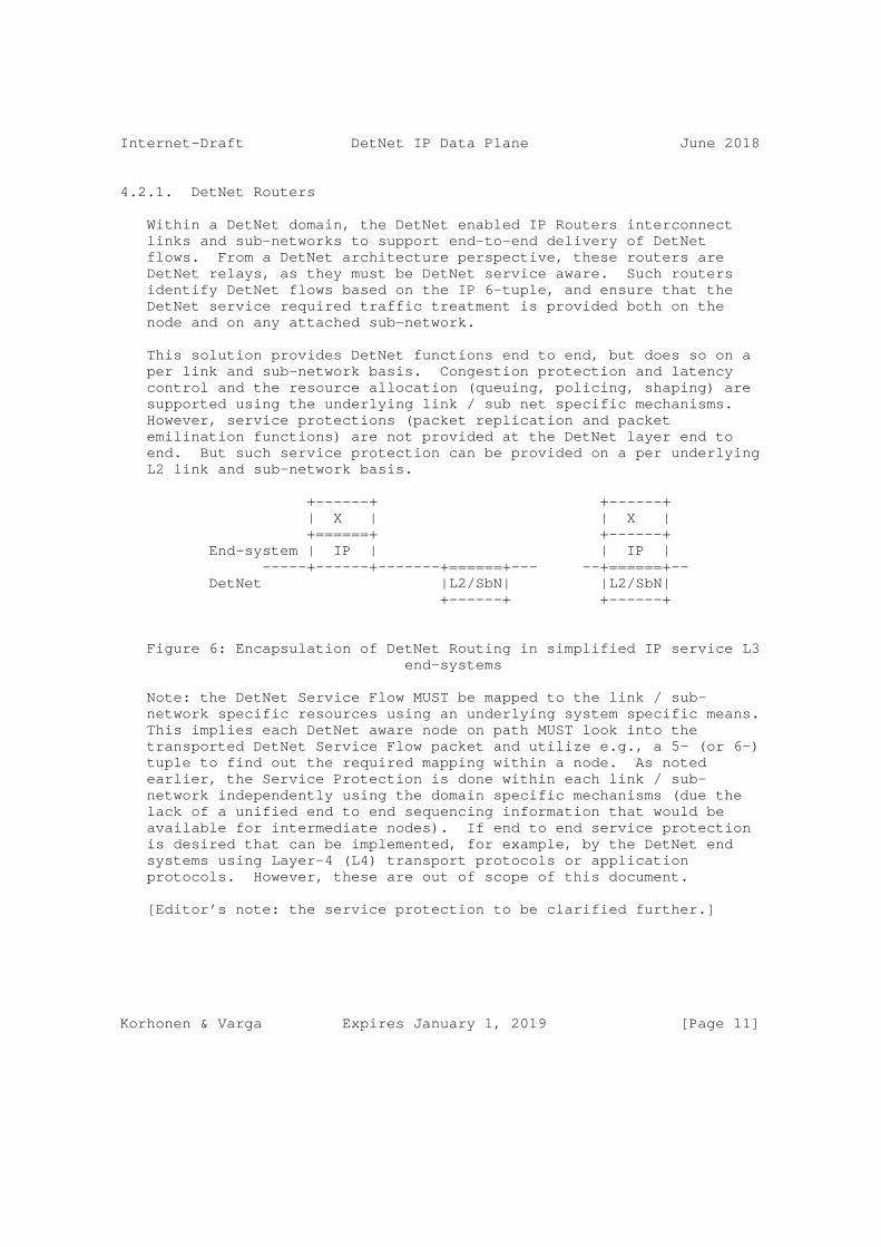
Internet-Draft DetNet IP Data Plane June 2018
4.2.1. DetNet Routers
Within a DetNet domain, the DetNet enabled IP Routers interconnect links and sub-networks to support end-to-end delivery of DetNet flows. From a DetNet architecture perspective, these routers are DetNet relays, as they must be DetNet service aware. Such routers identify DetNet flows based on the IP 6-tuple, and ensure that the DetNet service required traffic treatment is provided both on the node and on any attached sub-network.
This solution provides DetNet functions end to end, but does so on a per link and sub-network basis. Congestion protection and latency control and the resource allocation (queuing, policing, shaping) are supported using the underlying link / sub net specific mechanisms. However, service protections (packet replication and packet emilination functions) are not provided at the DetNet layer end to end. But such service protection can be provided on a per underlying L2 link and sub-network basis.
+------+ +------+ | X | | X | +======+ +------+ End-system | IP | | IP | -----+------+-------+======+--- --+======+-- DetNet |L2/SbN| |L2/SbN| +------+ +------+
Figure 6: Encapsulation of DetNet Routing in simplified IP service L3 end-systems
Note: the DetNet Service Flow MUST be mapped to the link / sub- network specific resources using an underlying system specific means. This implies each DetNet aware node on path MUST look into the transported DetNet Service Flow packet and utilize e.g., a 5- (or 6-) tuple to find out the required mapping within a node. As noted earlier, the Service Protection is done within each link / sub- network independently using the domain specific mechanisms (due the lack of a unified end to end sequencing information that would be available for intermediate nodes). If end to end service protection is desired that can be implemented, for example, by the DetNet end systems using Layer-4 (L4) transport protocols or application protocols. However, these are out of scope of this document.
[Editor’s note: the service protection to be clarified further.]
Korhonen & Varga Expires January 1, 2019 [Page 11]

Internet-Draft DetNet IP Data Plane June 2018
4.3. Networks with multiple technology segments
There are network scenarios, where the DetNet domain contains multiple technology segments (IEEE 802.1 TSN, MPLS) and all those segments are under the same administrative control (see Figure 7). Furthermore, DetNet nodes may be interconnected via TSN segments.
DetNet routers ensure that detnet service requirements are met per hop by allocating local resources, both receive and transmit, and by mapping the service requirements of each flow to appropriate sub- network mechanisms. Such mapping is sub-network technology specific. The mapping of IP DetNet Flows to MPLS is covered [I-D.ietf-detnet-dp-sol-mpls]. The mapping of IP DetNet Flows to IEEE 802.1 TSN is covered in Section 7.
______ _____ / \__ ____ / \__/ \___ ______ +----+ __/ +======+ +==+ \ +----+ |src |__/ Seg1 ) | | \ Seg3 \__| dst| +----+ \_______+ \ Segment-2 | \+_____/ +----+ \======+__ _+===/ \ __ __/ \_______/ \___/
Figure 7: DetNet domains and multiple technology segments
4.4. OAM
[Editor’s note: This section is TBD]
4.5. Class of Service
[Editor’s note: this section is TBD]
Class and quality of service, i.e., CoS and QoS, are terms that are often used interchangeably and confused. In the context of DetNet, CoS is used to refer to mechanisms that provide traffic forwarding treatment based on aggregate group basis and QoS is used to refer to mechanisms that provide traffic forwarding treatment based on a specific DetNet flow basis. Examples of existing network level CoS mechanisms include DiffServ which is enabled by IP header differentiated services code point (DSCP) field [RFC2474] and MPLS label traffic class field [RFC5462], and at Layer-2, by IEEE 802.1p priority code point (PCP).
Korhonen & Varga Expires January 1, 2019 [Page 12]

Internet-Draft DetNet IP Data Plane June 2018
CoS for DetNet flows carried in PWs and MPLS is provided using the existing MPLS Differentiated Services (DiffServ) architecture [RFC3270]. Both E-LSP and L-LSP MPLS DiffServ modes MAY be used to support DetNet flows. The Traffic Class field (formerly the EXP field) of an MPLS label follows the definition of [RFC5462] and [RFC3270]. The Uniform, Pipe, and Short Pipe DiffServ tunneling and TTL processing models are described in [RFC3270] and [RFC3443] and MAY be used for MPLS LSPs supporting DetNet flows. MPLS ECN MAY also be used as defined in ECN [RFC5129] and updated by [RFC5462].
CoS for DetNet flows carried in IPv6 is provided using the standard differentiated services code point (DSCP) field [RFC2474] and related mechanisms. The 2-bit explicit congestion notification (ECN) [RFC3168] field MAY also be used.
One additional consideration for DetNet nodes which support CoS services is that they MUST ensure that the CoS service classes do not impact the congestion protection and latency control mechanisms used to provide DetNet QoS. This requirement is similar to requirement for MPLS LSRs to that CoS LSPs do not impact the resources allocated to TE LSPs via [RFC3473].
4.6. Quality of Service
[Editor’s note: Keep this section. We should document the used technologies but the detailed discussion may go somewhere else. We should start having it here and then decide whether to move to some other document.]
Quality of Service (QoS) mechanisms for flow specific traffic treatment typically includes a guarantee/agreement for the service, and allocation of resources to support the service. Example QoS mechanisms include discrete resource allocation, admission control, flow identification and isolation, and sometimes path control, traffic protection, shaping, policing and remarking. Example protocols that support QoS control include Resource ReSerVation Protocol (RSVP) [RFC2205] (RSVP) and RSVP-TE [RFC3209] and [RFC3473]. The existing MPLS mechanisms defined to support CoS [RFC3270] can also be used to reserve resources for specific traffic classes.
In addition to explicit routes, and packet replication and elimination, DetNet provides zero congestion loss and bounded latency and jitter. As described in [I-D.ietf-detnet-architecture], there are different mechanisms that maybe used separately or in combination to deliver a zero congestion loss service. These mechanisms are provided by the either the MPLS or IP layers, and may be combined with the mechanisms defined by the underlying network layer such as 802.1TSN.
Korhonen & Varga Expires January 1, 2019 [Page 13]

Internet-Draft DetNet IP Data Plane June 2018
A baseline set of QoS capabilities for DetNet flows carried in PWs and MPLS can provided by MPLS with Traffic Engineering (MPLS-TE) [RFC3209] and [RFC3473]. TE LSPs can also support explicit routes (path pinning). Current service definitions for packet TE LSPs can be found in "Specification of the Controlled Load Quality of Service", [RFC2211], "Specification of Guaranteed Quality of Service", [RFC2212], and "Ethernet Traffic Parameters", [RFC6003]. Additional service definitions are expected in future documents to support the full range of DetNet services. In all cases, the existing label-based marking mechanisms defined for TE-LSPs and even E-LSPs are use to support the identification of flows requiring DetNet QoS.
QoS for DetNet service flows carried in IP MUST be provided locally by the DetNet-aware hosts and routers supporting DetNet flows. Such support will leverage the underlying network layer such as 802.1TSN. The traffic control mechanisms used to deliver QoS for IP encapsulated DetNet flows are expected to be defined in a future document. From an encapsulation perspective, the combination of the "6 tuple" i.e., the typical 5 tuple enhanced with the DSCP code, uniquely identifies a DetNet service flow.
Packets that are marked with a DetNet Class of Service value, but that have not been the subject of a completed reservation, can disrupt the QoS offered to properly reserved DetNet flows by using resources allocated to the reserved flows. Therefore, the network nodes of a DetNet network must:
o Defend the DetNet QoS by discarding or remarking (to a non-DetNet CoS) packets received that are not the subject of a completed reservation.
o Not use a DetNet reserved resource, e.g. a queue or shaper reserved for DetNet flows, for any packet that does not carry a DetNet Class of Service marker.
4.7. Cross-DetNet flow resource aggregation
[Editor’s note: Aggregation is FFS. The addregation can be provided via encapsulation or header wildcards]
The ability to aggregate individual flows, and their associated resource control, into a larger aggregate is an important technique for improving scaling of control in the data, management and control planes. This document identifies the traffic identification related aspects of aggregation of DetNet flows. The resource control and management aspects of aggregation (including the queuing/shaping/ policing implications) will be covered in other documents. The data
Korhonen & Varga Expires January 1, 2019 [Page 14]
Internet-Draft DetNet IP Data Plane June 2018
plane implications of aggregation are independent for PW/MPLS and IP encapsulated DetNet flows.
DetNet flows transported via IP have more limited aggregation options, due to the available traffic flow identification fields of the IP solution. One available approach is to manage the resources associated with a DSCP identified traffic class and to map (remark) individually controlled DetNet flows onto that traffic class. This approach also requires that nodes support aggregation ensure that traffic from aggregated LSPs are placed (shaped/policed/enqueued) in a fashion that ensures the required DetNet service is preserved.
In both the MPLS and IP cases, additional details of the traffic control capabilities needed at a DetNet-aware node may be covered in the new service descriptions mentioned above or in separate future documents. Management and control plane mechanisms will also need to ensure that the service required on the aggregate flow (H-LSP or DSCP) are provided, which may include the discarding or remarking mentioned in the previous sections.
4.8. Time synchronization
While time synchronization can be important both from the perspective of operating the DetNet network itself and from the perspective of DetNet-based applications, time synchronization is outside the scope of this document. This said, a DetNet node can also support time synchronization or distribution mechanisms.
For example, [RFC8169] describes a method of recording the packet queuing time in an MPLS LSR on a packet by per packet basis and forwarding this information to the egress edge system. This allows compensation for any variable packet queuing delay to be applied at the packet receiver. Other mechanisms for IP networks are defined based on IEEE Standard 1588 [IEEE1588], such as ITU-T [G.8275.1] and [G.8275.2].
A more detailed discussion of time synchronization is outside the scope of this document.
5. Management and control plane considerations
[Editor’s note: This section needs to be different for MPLS and IP solutions. Most solutions are technology dependant.]
While management plane and control plane are traditionally considered separately, from the Data Plane perspective there is no practical difference based on the origin of flow provisioning information. This document therefore does not distinguish between information
Korhonen & Varga Expires January 1, 2019 [Page 15]
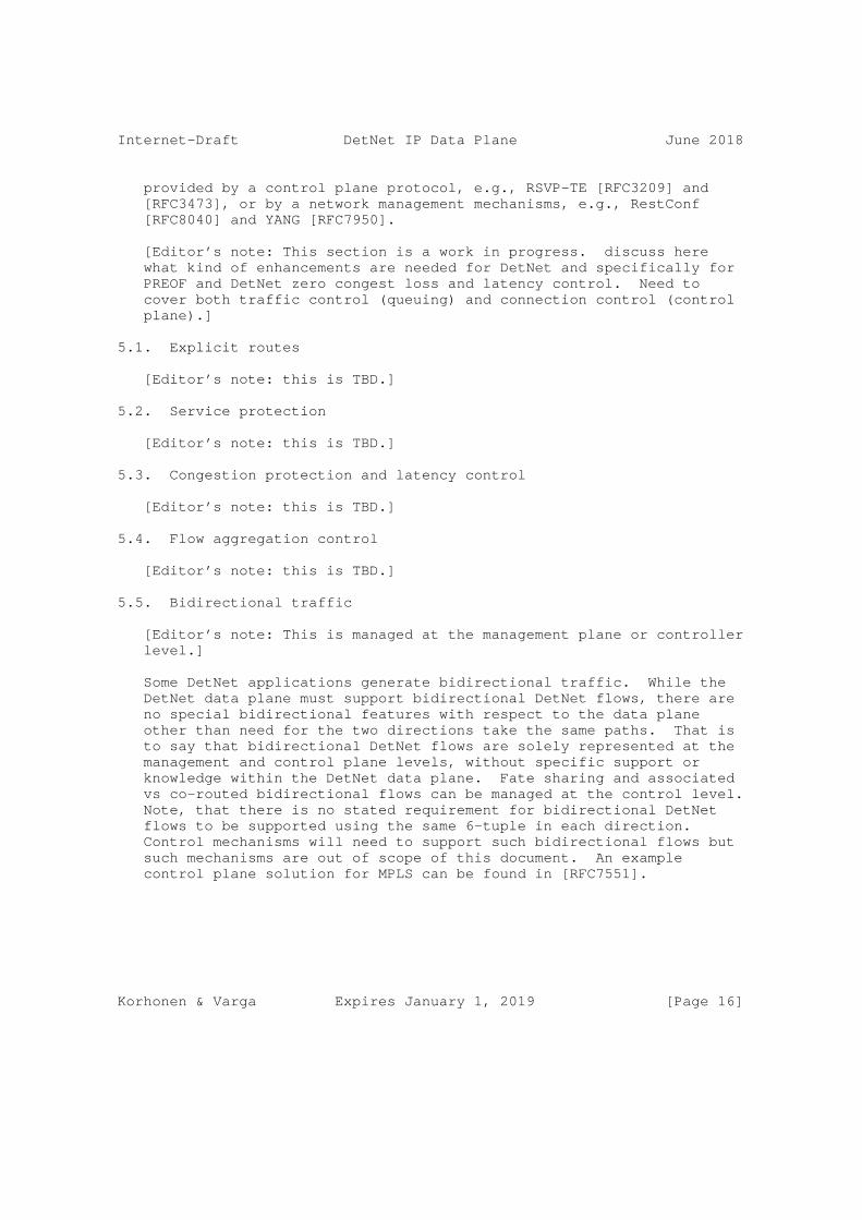
Internet-Draft DetNet IP Data Plane June 2018
provided by a control plane protocol, e.g., RSVP-TE [RFC3209] and [RFC3473], or by a network management mechanisms, e.g., RestConf [RFC8040] and YANG [RFC7950].
[Editor’s note: This section is a work in progress. discuss here what kind of enhancements are needed for DetNet and specifically for PREOF and DetNet zero congest loss and latency control. Need to cover both traffic control (queuing) and connection control (control plane).]
5.1. Explicit routes
[Editor’s note: this is TBD.]
5.2. Service protection
[Editor’s note: this is TBD.]
5.3. Congestion protection and latency control
[Editor’s note: this is TBD.]
5.4. Flow aggregation control
[Editor’s note: this is TBD.]
5.5. Bidirectional traffic
[Editor’s note: This is managed at the management plane or controller level.]
Some DetNet applications generate bidirectional traffic. While the DetNet data plane must support bidirectional DetNet flows, there are no special bidirectional features with respect to the data plane other than need for the two directions take the same paths. That is to say that bidirectional DetNet flows are solely represented at the management and control plane levels, without specific support or knowledge within the DetNet data plane. Fate sharing and associated vs co-routed bidirectional flows can be managed at the control level. Note, that there is no stated requirement for bidirectional DetNet flows to be supported using the same 6-tuple in each direction. Control mechanisms will need to support such bidirectional flows but such mechanisms are out of scope of this document. An example control plane solution for MPLS can be found in [RFC7551].
Korhonen & Varga Expires January 1, 2019 [Page 16]
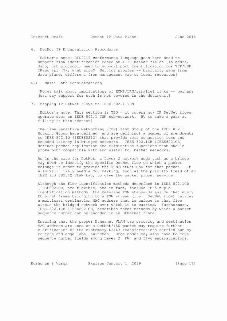
Internet-Draft DetNet IP Data Plane June 2018
6. DetNet IP Encapsulation Procedures
[Editor’s note: RFC2119 conformance language goes here Need to support flow identification Based on 4 IP header fields {ip addrs, dscp, nct protocol} need to support port identification for TCP/UDP, IPsec spi (?), what else? Service proxies -- basically same from data plane, different from management map to local resources]
6.1. Multi-Path Considerations
[Note: talk about implications of ECMP/LAG/parallel links -- perhaps just say support for such is not covered in the document.]
7. Mapping IP DetNet Flows to IEEE 802.1 TSN
[Editor’s note: This section is TBD - it covers how IP DetNet flows operate over an IEEE 802.1 TSN sub-network. BV to take a pass at filling in this section]
The Time-Sensitive Networking (TSN) Task Group of the IEEE 802.1 Working Group have defined (and are defining) a number of amendments to IEEE 802.1Q [IEEE8021Q] that provide zero congestion loss and bounded latency in bridged networks. IEEE 802.1CB [IEEE8021CB] defines packet replication and elimination functions that should prove both compatible with and useful to, DetNet networks.
As is the case for DetNet, a Layer 2 network node such as a bridge may need to identify the specific DetNet flow to which a packet belongs in order to provide the TSN/DetNet QoS for that packet. It also will likely need a CoS marking, such as the priority field of an IEEE Std 802.1Q VLAN tag, to give the packet proper service.
Although the flow identification methods described in IEEE 802.1CB [IEEE8021CB] are flexible, and in fact, include IP 5-tuple identification methods, the baseline TSN standards assume that every Ethernet frame belonging to a TSN stream (i.e. DetNet flow) carries a multicast destination MAC address that is unique to that flow within the bridged network over which it is carried. Furthermore, IEEE 802.1CB [IEEE8021CB] describes three methods by which a packet sequence number can be encoded in an Ethernet frame.
Ensuring that the proper Ethernet VLAN tag priority and destination MAC address are used on a DetNet/TSN packet may require further clarification of the customary L2/L3 transformations carried out by routers and edge label switches. Edge nodes may also have to move sequence number fields among Layer 2, PW, and IPv6 encapsulations.
Korhonen & Varga Expires January 1, 2019 [Page 17]

Internet-Draft DetNet IP Data Plane June 2018
7.1. TSN Stream ID Mapping
[Editor’s Note: This section covers the data plane aspects of mapping an IP DetNet flow to one or more TSN Stream-IDs.]
7.2. TSN Usage of FRER
[Core point] TSN Streams support DetNet flows may use Frame Replication and Elimination for Redundancy (FRER) [802.1CB] based on the loss service requirements of the TSN Stream, which is derived from the DetNet service requirements of the DetNet mapped flow. The specific operation of the FRER is not modified by the use of DetNe and follows IEEE 802.1CB [IEEE8021CB].
7.3. Management and Control Implications
[Editor’s note: This section is TBD Covers Creation, mapping, removal of TSN Stream IDs, related parameters and,when needed, configuration of FRER. Supported by management/control plane.]
8. Security considerations
The security considerations of DetNet in general are discussed in [I-D.ietf-detnet-architecture] and [I-D.ietf-detnet-security]. Other security considerations will be added in a future version of this draft.
9. IANA considerations
TBD.
10. Contributors
RFC7322 limits the number of authors listed on the front page of a draft to a maximum of 5, far fewer than the 20 individuals below who made important contributions to this draft. The editor wishes to thank and acknowledge each of the following authors for contributing text to this draft. See also Section 11.
Korhonen & Varga Expires January 1, 2019 [Page 18]

Internet-Draft DetNet IP Data Plane June 2018
Loa Andersson Huawei Email: [email protected]
Yuanlong Jiang Huawei Email: [email protected]
Norman Finn Huawei 3101 Rio Way Spring Valley, CA 91977 USA Email: [email protected]
Janos Farkas Ericsson Magyar Tudosok krt. 11 Budapest 1117 Hungary Email: [email protected]
Carlos J. Bernardos Universidad Carlos III de Madrid Av. Universidad, 30 Leganes, Madrid 28911 Spain Email: [email protected]
Tal Mizrahi Marvell 6 Hamada st. Yokneam Israel Email: [email protected]
Lou Berger LabN Consulting, L.L.C. Email: [email protected]
11. Acknowledgements
The author(s) ACK and NACK.
The following people were part of the DetNet Data Plane Solution Design Team:
Jouni Korhonen
Korhonen & Varga Expires January 1, 2019 [Page 19]

Internet-Draft DetNet IP Data Plane June 2018
Janos Farkas
Norman Finn
Balazs Varga
Loa Andersson
Tal Mizrahi
David Mozes
Yuanlong Jiang
Carlos J. Bernardos
The DetNet chairs serving during the DetNet Data Plane Solution Design Team:
Lou Berger
Pat Thaler
Thanks for Stewart Bryant for his extensive review of the previous versions of the document.
12. References
12.1. Normative references
[RFC0791] Postel, J., "Internet Protocol", STD 5, RFC 791, DOI 10.17487/RFC0791, September 1981, <https://www.rfc-editor.org/info/rfc791>.
[RFC2119] Bradner, S., "Key words for use in RFCs to Indicate Requirement Levels", BCP 14, RFC 2119, DOI 10.17487/RFC2119, March 1997, <https://www.rfc-editor.org/info/rfc2119>.
[RFC2211] Wroclawski, J., "Specification of the Controlled-Load Network Element Service", RFC 2211, DOI 10.17487/RFC2211, September 1997, <https://www.rfc-editor.org/info/rfc2211>.
[RFC2212] Shenker, S., Partridge, C., and R. Guerin, "Specification of Guaranteed Quality of Service", RFC 2212, DOI 10.17487/RFC2212, September 1997, <https://www.rfc-editor.org/info/rfc2212>.
Korhonen & Varga Expires January 1, 2019 [Page 20]

Internet-Draft DetNet IP Data Plane June 2018
[RFC2474] Nichols, K., Blake, S., Baker, F., and D. Black, "Definition of the Differentiated Services Field (DS Field) in the IPv4 and IPv6 Headers", RFC 2474, DOI 10.17487/RFC2474, December 1998, <https://www.rfc-editor.org/info/rfc2474>.
[RFC3168] Ramakrishnan, K., Floyd, S., and D. Black, "The Addition of Explicit Congestion Notification (ECN) to IP", RFC 3168, DOI 10.17487/RFC3168, September 2001, <https://www.rfc-editor.org/info/rfc3168>.
[RFC3209] Awduche, D., Berger, L., Gan, D., Li, T., Srinivasan, V., and G. Swallow, "RSVP-TE: Extensions to RSVP for LSP Tunnels", RFC 3209, DOI 10.17487/RFC3209, December 2001, <https://www.rfc-editor.org/info/rfc3209>.
[RFC3270] Le Faucheur, F., Wu, L., Davie, B., Davari, S., Vaananen, P., Krishnan, R., Cheval, P., and J. Heinanen, "Multi- Protocol Label Switching (MPLS) Support of Differentiated Services", RFC 3270, DOI 10.17487/RFC3270, May 2002, <https://www.rfc-editor.org/info/rfc3270>.
[RFC3443] Agarwal, P. and B. Akyol, "Time To Live (TTL) Processing in Multi-Protocol Label Switching (MPLS) Networks", RFC 3443, DOI 10.17487/RFC3443, January 2003, <https://www.rfc-editor.org/info/rfc3443>.
[RFC3473] Berger, L., Ed., "Generalized Multi-Protocol Label Switching (GMPLS) Signaling Resource ReserVation Protocol- Traffic Engineering (RSVP-TE) Extensions", RFC 3473, DOI 10.17487/RFC3473, January 2003, <https://www.rfc-editor.org/info/rfc3473>.
[RFC5129] Davie, B., Briscoe, B., and J. Tay, "Explicit Congestion Marking in MPLS", RFC 5129, DOI 10.17487/RFC5129, January 2008, <https://www.rfc-editor.org/info/rfc5129>.
[RFC5462] Andersson, L. and R. Asati, "Multiprotocol Label Switching (MPLS) Label Stack Entry: "EXP" Field Renamed to "Traffic Class" Field", RFC 5462, DOI 10.17487/RFC5462, February 2009, <https://www.rfc-editor.org/info/rfc5462>.
[RFC6003] Papadimitriou, D., "Ethernet Traffic Parameters", RFC 6003, DOI 10.17487/RFC6003, October 2010, <https://www.rfc-editor.org/info/rfc6003>.
Korhonen & Varga Expires January 1, 2019 [Page 21]

Internet-Draft DetNet IP Data Plane June 2018
[RFC8174] Leiba, B., "Ambiguity of Uppercase vs Lowercase in RFC 2119 Key Words", BCP 14, RFC 8174, DOI 10.17487/RFC8174, May 2017, <https://www.rfc-editor.org/info/rfc8174>.
[RFC8200] Deering, S. and R. Hinden, "Internet Protocol, Version 6 (IPv6) Specification", STD 86, RFC 8200, DOI 10.17487/RFC8200, July 2017, <https://www.rfc-editor.org/info/rfc8200>.
12.2. Informative references
[G.8275.1] International Telecommunication Union, "Precision time protocol telecom profile for phase/time synchronization with full timing support from the network", ITU-T G.8275.1/Y.1369.1 G.8275.1, June 2016, <https://www.itu.int/rec/T-REC-G.8275.1/en>.
[G.8275.2] International Telecommunication Union, "Precision time protocol telecom profile for phase/time synchronization with partial timing support from the network", ITU-T G.8275.2/Y.1369.2 G.8275.2, June 2016, <https://www.itu.int/rec/T-REC-G.8275.2/en>.
[I-D.ietf-detnet-architecture] Finn, N., Thubert, P., Varga, B., and J. Farkas, "Deterministic Networking Architecture", draft-ietf- detnet-architecture-05 (work in progress), May 2018.
[I-D.ietf-detnet-dp-sol-mpls] Korhonen, J., Varga, B., "DetNet MPLS Data Plane Encapsulation", 2018.
[I-D.ietf-detnet-security] Mizrahi, T., Grossman, E., Hacker, A., Das, S., Dowdell, J., Austad, H., Stanton, K., and N. Finn, "Deterministic Networking (DetNet) Security Considerations", draft-ietf- detnet-security-02 (work in progress), April 2018.
[IEEE1588] IEEE, "IEEE 1588 Standard for a Precision Clock Synchronization Protocol for Networked Measurement and Control Systems Version 2", 2008.
Korhonen & Varga Expires January 1, 2019 [Page 22]

Internet-Draft DetNet IP Data Plane June 2018
[IEEE8021CB] Finn, N., "Draft Standard for Local and metropolitan area networks - Seamless Redundancy", IEEE P802.1CB /D2.1 P802.1CB, December 2015, <http://www.ieee802.org/1/files/private/cb-drafts/ d2/802-1CB-d2-1.pdf>.
[IEEE8021Q] IEEE 802.1, "Standard for Local and metropolitan area networks--Bridges and Bridged Networks (IEEE Std 802.1Q- 2014)", 2014, <http://standards.ieee.org/about/get/>.
[RFC2205] Braden, R., Ed., Zhang, L., Berson, S., Herzog, S., and S. Jamin, "Resource ReSerVation Protocol (RSVP) -- Version 1 Functional Specification", RFC 2205, DOI 10.17487/RFC2205, September 1997, <https://www.rfc-editor.org/info/rfc2205>.
[RFC3670] Moore, B., Durham, D., Strassner, J., Westerinen, A., and W. Weiss, "Information Model for Describing Network Device QoS Datapath Mechanisms", RFC 3670, DOI 10.17487/RFC3670, January 2004, <https://www.rfc-editor.org/info/rfc3670>.
[RFC7551] Zhang, F., Ed., Jing, R., and R. Gandhi, Ed., "RSVP-TE Extensions for Associated Bidirectional Label Switched Paths (LSPs)", RFC 7551, DOI 10.17487/RFC7551, May 2015, <https://www.rfc-editor.org/info/rfc7551>.
[RFC7657] Black, D., Ed. and P. Jones, "Differentiated Services (Diffserv) and Real-Time Communication", RFC 7657, DOI 10.17487/RFC7657, November 2015, <https://www.rfc-editor.org/info/rfc7657>.
[RFC7950] Bjorklund, M., Ed., "The YANG 1.1 Data Modeling Language", RFC 7950, DOI 10.17487/RFC7950, August 2016, <https://www.rfc-editor.org/info/rfc7950>.
[RFC8040] Bierman, A., Bjorklund, M., and K. Watsen, "RESTCONF Protocol", RFC 8040, DOI 10.17487/RFC8040, January 2017, <https://www.rfc-editor.org/info/rfc8040>.
[RFC8169] Mirsky, G., Ruffini, S., Gray, E., Drake, J., Bryant, S., and A. Vainshtein, "Residence Time Measurement in MPLS Networks", RFC 8169, DOI 10.17487/RFC8169, May 2017, <https://www.rfc-editor.org/info/rfc8169>.
Korhonen & Varga Expires January 1, 2019 [Page 23]

Internet-Draft DetNet IP Data Plane June 2018
Appendix A. Example of DetNet data plane operation
[Editor’s note: Add a simplified example of DetNet data plane and how labels etc work in the case of MPLS-based PSN and utilizing PREOF. The figure is subject to change depending on the further DT decisions on the label handling..]
Appendix B. Example of pinned paths using IPv6
TBD.
Authors’ Addresses
Jouni Korhonen (editor)
Email: [email protected]
Balazs Varga (editor) Ericsson Magyar Tudosok krt. 11. Budapest 1117 Hungary
Email: [email protected]
Korhonen & Varga Expires January 1, 2019 [Page 24]

DetNet J. Korhonen, Ed.Internet-DraftIntended status: Standards Track B. Varga, Ed.Expires: January 1, 2019 Ericsson June 30, 2018
DetNet MPLS Data Plane Encapsulation draft-ietf-detnet-dp-sol-mpls-00
Abstract
This document specifies Deterministic Networking data plane encapsulation solutions. The described data plane solutions is applied over an MPLS Packet Switched Networks.
Status of This Memo
This Internet-Draft is submitted in full conformance with the provisions of BCP 78 and BCP 79.
Internet-Drafts are working documents of the Internet Engineering Task Force (IETF). Note that other groups may also distribute working documents as Internet-Drafts. The list of current Internet- Drafts is at https://datatracker.ietf.org/drafts/current/.
Internet-Drafts are draft documents valid for a maximum of six months and may be updated, replaced, or obsoleted by other documents at any time. It is inappropriate to use Internet-Drafts as reference material or to cite them other than as "work in progress."
This Internet-Draft will expire on January 1, 2019.
Copyright Notice
Copyright (c) 2018 IETF Trust and the persons identified as the document authors. All rights reserved.
This document is subject to BCP 78 and the IETF Trust’s Legal Provisions Relating to IETF Documents (https://trustee.ietf.org/license-info) in effect on the date of publication of this document. Please review these documents carefully, as they describe your rights and restrictions with respect to this document. Code Components extracted from this document must include Simplified BSD License text as described in Section 4.e of the Trust Legal Provisions and are provided without warranty as described in the Simplified BSD License.
Korhonen & Varga Expires January 1, 2019 [Page 1]

Internet-Draft DetNet MPLS Data Plane June 2018
Table of Contents
1. Introduction . . . . . . . . . . . . . . . . . . . . . . . . 3 2. Terminology . . . . . . . . . . . . . . . . . . . . . . . . . 3 2.1. Terms used in this document . . . . . . . . . . . . . . . 4 2.2. Abbreviations . . . . . . . . . . . . . . . . . . . . . . 4 3. Requirements language . . . . . . . . . . . . . . . . . . . . 6 4. MPLS DetNet data plane overview . . . . . . . . . . . . . . . 6 4.1. DetNet data plane encapsulation requirements . . . . . . 12 5. DetNet encapsulation . . . . . . . . . . . . . . . . . . . . 13 5.1. End-system specific considerations . . . . . . . . . . . 13 5.2. DetNet domain specific considerations . . . . . . . . . . 15 5.2.1. DetNet Layer Two Service . . . . . . . . . . . . . . 15 5.2.2. DetNet Routing Service (IP over MPLS) . . . . . . . . 16 5.3. DetNet Inter-Working Function (DN-IWF) . . . . . . . . . 17 5.3.1. Networks with multiple technology segments . . . . . 17 5.3.2. DN-IWF related considerations . . . . . . . . . . . . 18 6. MPLS-based DetNet data plane solution . . . . . . . . . . . . 19 6.1. DetNet over MPLS Encapsulation Components . . . . . . . . 19 6.2. MPLS data plane encapsulation . . . . . . . . . . . . . . 21 6.3. DetNet control word . . . . . . . . . . . . . . . . . . . 22 6.4. Flow Identification . . . . . . . . . . . . . . . . . . . 23 6.5. Indication of the DetNet Payload Type . . . . . . . . . . 23 6.6. OAM Indication . . . . . . . . . . . . . . . . . . . . . 24 6.7. Flow Aggregation . . . . . . . . . . . . . . . . . . . . 24 6.7.1. Aggregation at the LSP . . . . . . . . . . . . . . . 25 6.7.2. Aggregating DetNet flows as a new DetNet flow . . . . 25 6.7.3. Simple Aggregation at the DetNet layer . . . . . . . 26 6.8. Service Layer Considerations . . . . . . . . . . . . . . 27 6.8.1. Edge node processing . . . . . . . . . . . . . . . . 27 6.8.2. Relay node processing . . . . . . . . . . . . . . . . 28 6.9. Other DetNet data plane considerations . . . . . . . . . 29 6.9.1. Class of Service . . . . . . . . . . . . . . . . . . 29 6.9.2. Quality of Service . . . . . . . . . . . . . . . . . 30 6.9.3. Cross-DetNet flow resource aggregation . . . . . . . 31 6.9.4. Layer 2 addressing and QoS Considerations . . . . . . 32 6.9.5. Time Synchronization . . . . . . . . . . . . . . . . 32 7. Management and control considerations . . . . . . . . . . . . 33 7.1. MPLS-based data plane . . . . . . . . . . . . . . . . . . 33 7.1.1. S-Label assignment and distribution . . . . . . . . . 33 7.1.2. Explicit routes . . . . . . . . . . . . . . . . . . . 33 7.2. Packet replication and elimination . . . . . . . . . . . 34 7.3. Congestion protection and latency control . . . . . . . . 35 7.4. Bidirectional traffic . . . . . . . . . . . . . . . . . . 35 7.5. Flow aggregation control . . . . . . . . . . . . . . . . 35 8. DetNet IP Operation over DetNet MPLS Service . . . . . . . . 35 9. IEEE 802.1 TSN Interconnection over DetNet MPLS Service . . . 36 10. DetNet MPLS Transport Layer Operation over IEEE 802.1 TSN
Korhonen & Varga Expires January 1, 2019 [Page 2]

Internet-Draft DetNet MPLS Data Plane June 2018
Sub-Networks . . . . . . . . . . . . . . . . . . . . . . . . 36 11. DetNet MPLS Transport Layer Operation over IP DetNet PSNs . . 36 12. Security considerations . . . . . . . . . . . . . . . . . . . 38 13. IANA considerations . . . . . . . . . . . . . . . . . . . . . 38 14. Contributors . . . . . . . . . . . . . . . . . . . . . . . . 39 15. Acknowledgements . . . . . . . . . . . . . . . . . . . . . . 41 16. References . . . . . . . . . . . . . . . . . . . . . . . . . 41 16.1. Normative references . . . . . . . . . . . . . . . . . . 41 16.2. Informative references . . . . . . . . . . . . . . . . . 44 Appendix A. Example of DetNet data plane operation . . . . . . . 45 Authors’ Addresses . . . . . . . . . . . . . . . . . . . . . . . 46
1. Introduction
Deterministic Networking (DetNet) is a service that can be offered by a network to DetNet flows. DetNet provides these flows with a low packet loss rates and assured maximum end-to-end delivery latency. General background and concepts of DetNet can be found in [I-D.ietf-detnet-architecture].
This document specifies the DetNet data plane and the on-wire encapsulation of DetNet flows over an MPLS-based Packet Switched Network (PSN). The specified encapsulation provides the building blocks to enable the DetNet service layer functions and allow flow identification as described in the DetNet Architecture.
The DetNet transport layer functionality that provides congestion protection for DetNet flows is assumed to be in place in a DetNet node.
Furthermore, this document also describes how DetNet flows are identified, and how a DetNet Relay/Edge/Transit nodes works. It also describes the function and operation of the Packet Replication (PRF) Packet Elimination (PEF) and Packet Ordering (POF) functions in the MPLS data plane.
This document does not define the associated control plane functions, or Operations, Administration, and Maintenance (OAM). It also does not specify traffic handling capabilities required to deliver congestion protection and latency control for DetNet flows at the DetNet transport layer.
2. Terminology
Korhonen & Varga Expires January 1, 2019 [Page 3]

Internet-Draft DetNet MPLS Data Plane June 2018
2.1. Terms used in this document
This document uses the terminology established in the DetNet architecture [I-D.ietf-detnet-architecture] and the DetNet Data Plane Solution Alternatives [I-D.ietf-detnet-dp-alt].
T-Label A label used to identify the LSP used to transport a DetNet flow across an MPLS PSN, e.g., a hop-by-hop label used between label switching routers (LSR).
S-Label A DetNet "service" label that is used between DetNet nodes that implement also the DetNet service layer functions. An S-Label is also used to identify a DetNet flow at DetNet service layer.
PEF A Packet Elimination Function (PEF) eliminates duplicate copies of packets received by an edge or a relay node to prevent excess packets flooding the network, or to prevent duplicate packets being sent out of the DetNet domain.
PRF A Packet Replication Function (PRF) replicates DetNet flow packets in an edge or a relay node and forwards them to one or more next hops in the DetNet domain. The number of packet copies sent to each next hop is a DetNet Flow specific parameter at the node doing the replication.
POF A Packet Order Function (POF) re-orders packets within a DetNet flow that are received out of order. This function may be implemented at an edge or a relay node.
PREOF Collective name for Packet Replication, Elimination, and Ordering Functions.
d-CW A DetNet Control Word (d-CW) is used for sequencing and identifying duplicate packets of a DetNet flow at the DetNet service layer.
2.2. Abbreviations
The following abbreviations used in this document:
AC Attachment Circuit.
CE Customer Edge equipment.
CoS Class of Service.
Korhonen & Varga Expires January 1, 2019 [Page 4]

Internet-Draft DetNet MPLS Data Plane June 2018
CW Control Word.
d-CW DetNet Control Word.
DetNet Deterministic Networking.
DF DetNet Flow.
DN-IWF DetNet Inter-Working Function.
L2 Layer 2.
L2VPN Layer 2 Virtual Private Network.
L3 Layer 3.
LSR Label Switching Router.
MPLS Multiprotocol Label Switching.
MPLS-TE Multiprotocol Label Switching - Traffic Engineering.
MPLS-TP Multiprotocol Label Switching - Transport Profile.
MS-PW Multi-Segment PseudoWire (MS-PW).
NSP Native Service Processing.
OAM Operations, Administration, and Maintenance.
PE Provider Edge.
PEF Packet Elimination Function.
PRF Packet Replication Function.
PREOF Packet Replication, Elimination and Ordering Functions.
POF Packet Ordering Function.
PSN Packet Switched Network.
PW PseudoWire.
QoS Quality of Service.
S-PE Switching Provider Edge.
Korhonen & Varga Expires January 1, 2019 [Page 5]

Internet-Draft DetNet MPLS Data Plane June 2018
T-PE Terminating Provider Edge.
TSN Time-Sensitive Network.
3. Requirements language
The key words "MUST", "MUST NOT", "REQUIRED", "SHALL", "SHALL NOT", "SHOULD", "SHOULD NOT", "RECOMMENDED", "NOT RECOMMENDED", "MAY", and "OPTIONAL" in this document are to be interpreted as described in BCP 14 [RFC2119] [RFC8174] when, and only when, they appear in all capitals, as shown here.
4. MPLS DetNet data plane overview
This document describes how DetNet flows are carried over MPLS networks. The DetNet Architecture, [I-D.ietf-detnet-architecture], decomposes the DetNet data plane into two layers: a service layer and a transport layer. The basic approach defined in this document supports the DetNet service layer based on existing pseudowire (PW) encapsulations and mechanisms, and supports the DetNet transport layer based on existing MPLS Traffic Engineering encapsulations and mechanisms. Background on PWs can be found in [RFC3985] and [RFC3031].
DetNet MPLS . . +-----------+ | Service | d-CW, S-Label +-----------+ | Transport | T-Label(s) +-----------+ . .
Figure 1: DetNet adaptation to MPLS data plane
The MPLS DetNet data plane approach defined in this document is shown in Figure 1. The service layer is supported by a DetNet control word (d-CW) which conforms to the Generic PW MPLS Control Word (PWMCW) defined in [RFC4385]. A d-CW identifying service label (S-Label) is also used. The transport layer is supported by one or labels (T-Labels).
Korhonen & Varga Expires January 1, 2019 [Page 6]

Internet-Draft DetNet MPLS Data Plane June 2018
TSN Edge Transit Edge TSN End System Node Node Node End System (T-PE) (LSR) (T-PE)
+---------+ +.........+ +.........+ +---------+ | Appl. |<--:Svc Proxy:--End to End Svc.--:Svc Proxy:-->| Appl. | +---------+ +---------+ +---------+ +---------+ | TSN | |TSN| |Svc|<-- DetNet flow -->: Service :-->| TSN | +---------+ +---+ +---+ +---------+ +---------+ +---------+ |Transport| |Trp| |Trp| |Transport| |Trp| |Trp| |Transport| +-------.-+ +--.+ +-.-+ +--.----.-+ +-.-+ +-.-+ +---.-----+ : Link : / ,-----. \ : Link : / ,-----. \ +........+ +-[ Sub ]-+ +........+ +-[ Sub ]-+ [Network] [Network] ‘-----’ ‘-----’
|<- TSN ->| |<----- DetNet MPLS ---->| |<-- TSN --->|
Figure 2: A TSN over DetNet MPLS Enabled Network
Figure 2 shows several node types defined in [I-D.ietf-detnet-architecture]. DetNet Edge Nodes sit at the boundary of a DetNet domain. They are responsible for mapping non- DetNet aware traffic to DetNet services. They also support the imposition and disposition of the required DetNet encapsulation. These are functionally similar to pseudowire (PW) Terminating Provider Edge (T-PE) nodes which use MPLS-TE LSPs.
Transit nodes are normal MPLS Label Switching Routers (LSRs). They are generally unaware of the special requirements of DetNet flows, although they need to provide traffic engineering services and proper QoS to the LSPs associated with DetNet flows to enhance the prospect of the LSPs meeting the DetNet service requirements. Some implementations of transit nodes may be DetNet aware, but such nodes just support the DetNet transport layer.
The MPLS LSP may be provided by any MPLS method (provisioned, RSVP- TE, MPLS- TP, or MPLS Segment Routing (SR)).
Korhonen & Varga Expires January 1, 2019 [Page 7]

Internet-Draft DetNet MPLS Data Plane June 2018
IP DetNet Relay Transit Relay IP DetNet End System Node Node Node End System (T-PE) (LSR) (T-PE) +---------+ +---------+ | Appl. |<--------------- End to End Service ---------->| Appl. | +---------+ .....-----+ +-----..... +---------+ | Service |<---: Service |-- DetNet flow ---| Service :-->| Service | +---------+ +---------+ +---------+ +---------+ +---------+ |Transport| |Trp| |Trp| |Transport| |Trp| |Trp| |Transport| +-------.-+ +-.-+ +-.-+ +---.---.-+ +-.-+ +-.-+ +---.-----+ : Link : / ,-----. \ : Link : / ,-----. \ +........+ +-[ Sub ]-+ +........+ +-[ Sub ]-+ [Network] [Network] ‘-----’ ‘-----’
|<-DN IP->| |<---- DetNet MPLS ---->| |<-DN IP->|
Figure 3: DetNet (DN) IP Over MPLS Network
Figure 3 and Figure 4, show different cases where relay nodes may be used. Relay nodes are similar to edge nodes in that both are aware of the needs of particular DetNet flows and take care to process them in accordance with the required performance needs. They differ in that relay nodes sit within a DetNet domain while edge nodes always sit at DetNet domain boundaries. Both node types can enhance the reliability of delivery by enabling the replication of packets so that multiple copies, possibly over multiple paths are forwarded through the DetNet domain. They also reduce the impact of replication by eliminating surplus copies of DetNet packets. Relay nodes may sit the boundary of an MPLS domain when the non-MPLS domain is DetNet aware. Relay nodes are functionally similar to PW S-PEs or, when at the edge of an MPLS network, T-PEs [RFC6073].
Figure 4 illustrates how DetNet can provide services for IEEE 802.1TSN end systems, CE1 and CE2, over a DetNet enabled network. The edge nodes, E1 and E2, insert and remove required DetNet data plane encapsulation. The ’X’ in the edge nodes and relay node, R1, represent a potential DetNet flow packet replication and elimination point. This conceptually parallels L2VPN services, and could leverage existing related solutions as discussed below.
Korhonen & Varga Expires January 1, 2019 [Page 8]

Internet-Draft DetNet MPLS Data Plane June 2018
TSN |<------- End to End DetNet Service ------>| TSN Service | Transit Transit | Service TSN (AC) | |<-Tnl->| |<-Tnl->| | (AC) TSN End | V V 1 V V 2 V V | End System | +--------+ +--------+ +--------+ | System +---+ | | E1 |=======| R1 |=======| E2 | | +---+ | |--|----|._X_....|..DF1..|.._ _...|..DF3..|...._X_.|---|---| | |CE1| | | \ | | X | | / | | |CE2| | | | \_.|..DF2..|._/ \_..|..DF4..|._/ | | | +---+ | |=======| |=======| | +---+ ^ +--------+ +--------+ +--------+ ^ | Edge Node Relay Node Edge Node | | (T-PE) (S-PE) (T-PE) | | | |<--TSN--> <---- TSN Over DetNet MPLS ----> <--TSN-->| | | |<--- Emulated Time Sensitive Networking (TSN) Service --->|
DFx = DetNet Flow x
Figure 4: IEEE 802.1TSN over DetNet
Figure 5 illustrates how an end to end MPLS-based DetNet service is provided in a more detail. In this case, the end systems, CE1 and CE2, are able to send and receive DetNet flows, and R1 and R2 are relay nodes as they sit in the middle of a DetNet network. For example, an end system sends data encapsulated in MPLS. The ’X’ in the end systems, and relay nodes represents potential DetNet flow packet replication and elimination points. Here the relay nodes may change the underlying transport, for example tunneling MPLS over IP Section 11, or simply interconnect network segments.
Korhonen & Varga Expires January 1, 2019 [Page 9]

Internet-Draft DetNet MPLS Data Plane June 2018
DetNet DetNet MPLS Service Transit Transit Service MPLS DetNet | |<-Tnl->| |<-Tnl->| | DetNet End | V 1 V V 2 V | End System | +--------+ +--------+ +--------+ | System +---+ | | R1 |=======| R2 |=======| R3 | | +---+ | X...DFa...|._X_....|..DF1..|.__ ___.|..DF3..|...._X_.|.DFa..|.X | |CE1|========| \ | | X | | / |======|CE2| | | | | \_.|..DF2..|._/ \__.|..DF4..|._/ | | | | +---+ | |=======| |=======| | +---+ ^ +--------+ +--------+ +--------+ ^ | Relay Node Relay Node Relay Node | | (S-PE) (S-PE) (S-PE) | | | |<---------------------- DetNet MPLS --------------------->| | | |<--------------- End to End DetNet Service -------------->|
Figure 5: MPLS-Based Native DetNet
Figure 6 illustrates how an end to end MPLS-based DetNet service is provided where the end systems are not able to send and receive DetNet flows. In this example, the nodes labeled CE1 and CE2 could be non-DetNet aware IP routers or hosts. Note that E1 and E2 are edge nodes as they sit boundaries of the DetNet enabled domain.
IP IP Non Service Transit Transit Service Non DetNet |<-Tnl->| |<-Tnl->| DetNet End | V 1 V V 2 V | End System | +--------+ +--------+ +--------+ | System +---+ | | E1 |=======| R2 |=======| E3 | | +---+ | |--------|._X_....|..DF1..|.__ ___.|..DF3..|...._X_.|------| | |CE1| | | \ | | X | | / | | |CE2| | | | | \_.|..DF2..|._/ \__.|..DF4..|._/ | | | | +---+ | |=======| |=======| | +---+ +--------+ +--------+ +--------+ ^ Edge Node Relay Node Edge Node^ | (T-PE) (S-PE) (T-PE) | | | <--IP-->| <----- IP Over DetNet MPLS ----> |<--IP--> | | |<------ End to End DetNet Service ------->|
Figure 6: MPLS-Based DetNet (non-MPLS End System)
Figure 7 illustrates how end to end DetNet service is provided where the end systems are able to send and receive IP DetNet flows, e.g.,
Korhonen & Varga Expires January 1, 2019 [Page 10]

Internet-Draft DetNet MPLS Data Plane June 2018
per [I-D.ietf-detnet-dp-sol-ip], and the MPLS nodes optionally provide service protection. In this case R1 and R3 are T-PEs and R2 is an S-PE and the DetNet service is end-to-end.
DetNet DetNet IP Service Transit Transit Service IP DetNet |<-Tnl->| |<-Tnl->| DetNet End | V 1 V V 2 V | End System | +--------+ +--------+ +--------+ | System +---+ | | R1 |=======| R2 |=======| R3 | | +---+ | |--------|._X_....|..DF1..|.__ ___.|..DF3..|...._X_.|------| | |CE1| | | \ | | X | | / | | |CE2| | | | | \_.|..DF2..|._/ \__.|..DF4..|._/ | | | | +---+ | |=======| |=======| | +---+ ^ +--------+ +--------+ +--------+ ^ | Relay Node Relay Node Relay Node | | (T-PE) (S-PE) (T-PE) | | | |<-DN IP-> <------ DetNet MPLS ------> <-DN IP->| | | |<--------------- End to End DetNet Service -------------->|
Figure 7: DetNet IP over DetNet (DN) MPLS
An example MPLS DetNet network fragment and packet flow is illustrated in Figure 8.
1 1.1 1.1 1.2.1 1.2.1 1.2.2 CE1----EN1--------R1-------R2-------R3--------EN2-----CE2 \ 1.2.1 / / \1.2 /-----+ / +------R4------------------------+ 1.2.2
Figure 8: Example Packet flow in DetNet Enabled MPLS Network
In Figure 8 the numbers are used to identify the instance of a packet. Packet 1 is the original packet, and packets 1.1, and 1.2 are two first generation copies of packet 1. Packet 1.2.1 is a second generation copy of packet 1.2 etc. Note that these numbers never appear in the packet, and are not to be confused with sequence numbers, labels or any other identifier that appears in the packet. They simply indicate the generation number of the original packet so that its passage through the network fragment can be identified to the reader.
Customer Equipment CE1 sends a packet into the DetNet enabled MPLS network. This is packet (1). Edge Node EN1 encapsulates the packet
Korhonen & Varga Expires January 1, 2019 [Page 11]

Internet-Draft DetNet MPLS Data Plane June 2018
as a DetNet Packet and sends it to Relay node R1 (packet 1.1). EN1 makes a copy of the packet (1.2), encapsulates it and sends this copy to Relay node R4.
Note that along the MPLS path from EN1 to R1 there may be zero or more LSRs which, for clarity, are not shown. The same is true for any other path between two DetNet entities shown in Figure 8.
Relay node R4 has been configured to send one copy of the packet to Relay Node R2 (packet 1.2.1) and one copy to Edge Node EN2 (packet 1.2.2).
R2 receives packet copy 1.2.1 before packet copy 1.1 arrives, and, having been configured to perform packet elimination on this DetNet flow, forwards packet 1.2.1 to Relay Node R3. Packet copy 1.1 is of no further use and so is discarded by R2.
Edge Node EN2 receives packet copy 1.2.2 from R4 before it receives packet copy 1.2.1 from R2 via relay Node R3. EN2 therefore strips any DetNet encapsulation from packet copy 1.2.2 and forwards the packet to CE2. When EN2 receives the later packet copy 1.2.1 this is discarded.
The above is of course illustrative of many network scenarios that can be configured. Between a pair of relay nodes there may be one or more transport nodes that simply forward the DetNet traffic, but these are omitted for clarity.
4.1. DetNet data plane encapsulation requirements
Two major groups of scenarios can be distinguished which require flow identification during transport:
1. DetNet function related scenarios:
* Congestion protection and latency control: usage of allocated resources (queuing, policing, shaping).
* Explicit routes: select/apply the flow specific path.
* Service protection: recognize DetNet compound and member flows for replication an elimination.
2. OAM function related scenarios:
* troubleshooting (e.g., identify misbehaving flows, etc.)
Korhonen & Varga Expires January 1, 2019 [Page 12]

Internet-Draft DetNet MPLS Data Plane June 2018
* recognize flow(s) for analytics (e.g., increase counters, etc.)
* correlate events with flows (e.g., volume above threshold, etc.)
* etc.
The DetNet data plane allows for the aggregation of DetNet flows, e.g., via MPLS hierarchical LSPs, to improved scaling. When DetNet flows are aggregated, transit nodes may have limited ability to provide service on per-flow DetNet identifiers. Therefore, identifying each individual DetNet flow on a transit node may not be achieved in some network scenarios, but DetNet service can still be assured in these scenarios through resource allocation and control.
A node operating on a DetNet flow in the Detnet layer, i.e. a node processing a DetNet packet which has the S-label as top of stack uses the local context associated with that S-label to determine what local operation(s) are applied to that packet. The S-label has to be unique on each edge and relay node, which is achieved by using a label taken from the platform label space [RFC3031].
5. DetNet encapsulation
5.1. End-system specific considerations
Data-flows requiring DetNet service are generated and terminated on end-systems. Encapsulation depends on application and its preferences. In a DetNet (or even a TSN) domain the DN (TSN) functions use at most two flow parameters, namely Flow-ID and Sequence Number. However, an application may exchange further flow related parameters (e.g., time-stamp), which are not considered by DN functions.
Two types of end-systems are distinguished:
o L2 (Ethernet) end-system: application directly over L2.
o L3 (IP) end-system: application over L3.
In case of Ethernet end-systems the application data is encapsulated directly in L2. From the DN domain perspective no upper layer protocols are visible. The Data-flow uses only Ethernet tag(s) and further flow specific parameters (if needed) are hidden inside the protocol data unit (PDU).
Korhonen & Varga Expires January 1, 2019 [Page 13]

Internet-Draft DetNet MPLS Data Plane June 2018
The IP end-system scenario is different. Data-flows are encapsulated directly in L3 (i.e., IP) and the application may use further upper layer protocols (e.g., Real-time Transport Protocol (RTP)). Many valid combinations exist, and it may be application specific how the IP header fields are used. Also, usage of further upper layer protocols depends on application requirements (e.g., time-stamp). See [I-D.ietf-detnet-dp-sol-ip] more details.
[Editor’s note: IP solution document does not really detail anything beyond 6-tuple.]
As a general rule, DetNet domains MUST be capable of forwarding any Data-flows and the DetNet domain MUST NOT mandate the end-system encapsulation format.
Furthermore, no application-level-proxy function is envisioned inside the DetNet domain, so end-systems peer with end-systems using the same application encapsulation format (see figure below):
o L2 end-systems peer with L2 end-systems and
o L3 end-systems peer with L3 end-systems.
+-----+ | X | +-----+ +-----+ | X | | Eth | ________ +-----+ +-----+ _____ / \ | Eth | \ / \__/ \___ +-----+ \ / \ / 0======== tunnel-1 ========0_ | \ \ | 0========= tunnel-2 =========0 / \ __/ \ +-----+ \__ DetNet domain / \ | X | \ __ / +-----+ +-----+ \_______/ \_____/ | X | | IP | +-----+ +-----+ | IP | +-----+
Figure 9: End-systems and the DetNet domain
Korhonen & Varga Expires January 1, 2019 [Page 14]

Internet-Draft DetNet MPLS Data Plane June 2018
5.2. DetNet domain specific considerations
From a connection type perspective, three scenarios are distinguished:
1. Directly attached: end-system is directly connected to an edge node.
2. Indirectly attached: end-system is behind a (L2-TSN / L3-DetNet) sub-network.
3. DN integrated: end-system is part of the DetNet domain.
L3 end-systems may use any of these connection types, however L2 end- systems may use only the first two (directly or indirectly attached). DetNet domain MUST allow communication between any end-systems of the same type (L2-L2, L3-L3), independent of their connection type and DetNet capability. However directly attached and indirectly attached end-systems have no knowledge about the DetNet domain and its encapsulation format at all. See Figure 10 for L3 end-system scenarios.
____+----+ +----+ _____ / | ES3| | ES1|____ / \__/ +----+___ +----+ \ / \ + | ____ \ _/ +----+ __/ \ +__ DetNet domain / | ES2|____/ L2/L3 |___/ \ __ __/ +----+ \_______/ \_______/ \___/
Figure 10: Connection types of L3 end-systems
5.2.1. DetNet Layer Two Service
The simplest DetNet service is to provide tunneling for layer two, where the connected hosts are in the same broadcast (BC) domain. Forwarding over the DetNet domain is based on L2 (MAC) addresses (i.e. dst-MAC), or on received interface [RFC3985]. In both cases the L2 headers MUST either be kept, or provision must be made for their reconstruction at egress from the DetNet domain.
Korhonen & Varga Expires January 1, 2019 [Page 15]

Internet-Draft DetNet MPLS Data Plane June 2018
+------+ | X | +------+ +------+ | X | | IP | +------+ +------+ End-system | L2 | | L2 | +-----+======+-+======+--+------+ DetNet tunnel | Shim | +------+ | MPLS | +------+ | L2 | +------+
Examples:
+------+ +------+ | X | | X | +------+ +------+ +------+ | X | | IP | | IP | +------+ +------+ +------+ | L2 | | L2 | | L2 | +-----+======+--+======+--+======+-----+ | d-CW | | d-CW | | d-CW | +------+ +------+ +------+ | MPLS | | MPLS | | MPLS | +------+ +------+ +------+ | L2 | | L2 | | UDP | +------+ +------+ +------+ | IP | +------+ | L2 | +------+
Figure 11: Encapsulation format for DetNet Layer Two Service
As shown in Figure 11 both L2 and L3 end-systems can be served by such a DetNet L2 encapsulation service. This encapsulation service may be carried over MPLS natively Section 6.2, of over MPLS over IP Section 11.
5.2.2. DetNet Routing Service (IP over MPLS)
IP traffic and IP DetNet flows, see [I-D.ietf-detnet-dp-sol-ip], can be carried over a DetNet MPLS domain. In such cases, the IP headers are modified per standard router behavior, e.g., TTL handling.
Korhonen & Varga Expires January 1, 2019 [Page 16]

Internet-Draft DetNet MPLS Data Plane June 2018
Figure 12 shows the encapsulation of an IP flow over MPLS as well as when MPLS is carried over an IP PSN, see Section 11.
+------+ | X | +------+ End-system | IP | +-----+======+--+------+ DetNet tunnel | Shim | +------+ | MPLS | +------+ | L2 | +------+
Examples:
+------+ +------+ | X | | X | +------+ +------+ | IP | | IP | +-----+======+--+======+-----+ | d-CW | | d-CW | +------+ +------+ | MPLS | | MPLS | +------+ +------+ | L2 | | UDP | +------+ +------+ | IP | +------+ | L2 | +------+
Figure 12: Encapsulation format for DetNet Routing in MPLS PSN for L3 end-systems
5.3. DetNet Inter-Working Function (DN-IWF)
5.3.1. Networks with multiple technology segments
There are networking scenarios, where the DetNet domain contains multiple technology segments (IP, MPLS, ..) and all those segments are under the same administrative control (see Figure 13). Furthermore, DetNet nodes may be interconnected via TSN segments.
Korhonen & Varga Expires January 1, 2019 [Page 17]

Internet-Draft DetNet MPLS Data Plane June 2018
An important aspect of DetNet network design is the placement of DetNet functions across the domain. Designs based on segment-by- segment optimization can provide only sub-optimal solutions. In order to achieve global optimized Inter-Working Functions (DN-IWF) can be placed at segment edge nodes, which stitch together DetNet flows across connected segments.
DN-IWF may ensure that flow attributes are correlated across segment edges. For example, there are two DetNet functions which require Sequence Numbers: (1) PEF: removes duplications from flows and (2) POF: ensures in-order-delivery of packet in a flow. Stitching flows together and correlating attributes means for example that replication of packets can happen in one segment and elimination of duplicates in a different one.
______ ____ / \__ ____ / \__/ \___ ______ +----+ __/ +======+ +==+ \ +----+ |src |__/ Seg1 ) | | \ Seg3 \____| dst| +----+ \_______+ \ Segment-2 | \+_____/ +----+ \======+_ _+===/ \ __ __/ \_______/ \___/
+------------+ +---------------E----+ | | +----+ | | +----R---+ | +----+ |src |-------R +---+ | E----------+ dst| +----+ | | E--------+ +----+ +-----------R | +-----------------+
Figure 13: Optimal replication and elimination placement across technology segments example
5.3.2. DN-IWF related considerations
The goal of DN-IWF is to (1) match and (2) translate segment specific flow attributes. The DN-IWF ensures that segment specific attributes comprise per domain unique attributes for the whole DetNet domain. This characteristic can ensure that DetNet functions can be based on per domain attributes and not per segment attributes.
The two DetNet specific attributes have the following characteristics:
Korhonen & Varga Expires January 1, 2019 [Page 18]

Internet-Draft DetNet MPLS Data Plane June 2018
o Flow-ID: it is same in all packets of a flow
o Sequence Number: it is different packet-by-packet
For the Flow-ID the DN-IWF can implement a static mapping. The situation is more complicated for Sequence Number as it is different packet-by-packet, so it may need more sophisticated translation unless its format is exactly the same in the two technology segments. In this later case the DN-IWF can simple copy the Sequence Number field between the tunneling encapsulation of the two technology segments.
In case of three technology segments (IP, MPLS and TSN) three DN-IWF functions can be specified. In the rest of this section the focus is on the (1) IP - MPLS network scenario. Note: the use-cases are out- of-scope for (2) TSN - IP, (3) TSN - MPLS.
Simplest implementation of DN-IWF is provided if the flow attributes have the same format. Such a common denominator of the tunnel encapsulation format is the pseudowire encapsulation over both IP and MPLS.
+--------+ | | | X X | | ____ | | / \ | | | |/\/\/\/\|
Oops! 404 Not Found
Figure 14: FIGURE Placeholder PW over X
[Editor’s note: Where is the text describing how 802.1 TSN Streams are mapping to DetNet services/flows. i.e., EVPN+]
6. MPLS-based DetNet data plane solution
6.1. DetNet over MPLS Encapsulation Components
To carry DetNet over MPLS the following is required:
1. A method of identifying the MPLS payload type.
Korhonen & Varga Expires January 1, 2019 [Page 19]

Internet-Draft DetNet MPLS Data Plane June 2018
2. A method of identifying the DetNet flow group to the processing element.
3. A method of distinguishing DetNet OAM packets from DetNet data packets.
4. A method of carrying the DetNet sequence number.
5. A suitable LSP to deliver the packet to the egress PE.
6. A method of carrying queuing and forwarding indication.
In this design an MPLS service label (the S-Label), similar to a pseudowire (PW) label [RFC3985], is used to identify both the DetNet flow identity and the payload MPLS payload type satisfying (1) and (2) in the list above. OAM traffic discrimination happens through the use of the Associated Channel method described in [RFC4385]. The sequence number is carried in the DetNet Control word which carries the Data/OAM discriminator. The LSP used to transport the DetNet packet may be of any type (MPLS-LDP, MPLS-TE, MPLS-TP [RFC5921], or MPLS-SR [I-D.ietf-spring-segment-routing-mpls]). The LSP (T-Label) label and/or the S-Label may be used to indicate the queue processing as well as the forwarding parameters.
To simplify implementation and to maximize interoperability two sequence number sizes are supported: a 16 bit sequence number and a 28 bit sequence number. The 16 bit sequence number is needed to support some types of legacy clients. The 28 bit sequence number is used in situations where it is necessary ensure that in high speed networks the sequence number space does not wrap whilst packets are in flight. In addition it must be possible to send a packet with a zero length sequence number, to support the case where sequence numbers are not required by a particular DetNet flow.
Note that the concept of a zero length sequence number is not to be confused with a sequence number of zero. For example, were the sequence number size is 16 bits, the sequence will contain: 65535, 0, 1. In this case zero is an ordinary sequence number. Unlike [RFC4448] a sequence number of zero does not indicate that no sequence number is in use. Where sequence numbers are not in use, and thus a zero length sequence number is in used, the sequence number field in the packet is sent as zero. The DetNet packet forwarder knows which of these cases applies through configuration parameters associated with each specific DetNet flow.
Note that when the network consists only of DetNet enabled nodes with no aggregation, Penultimate Hop Popping (PHP) means that the only label in the label stack may be the S-label.
Korhonen & Varga Expires January 1, 2019 [Page 20]

Internet-Draft DetNet MPLS Data Plane June 2018
6.2. MPLS data plane encapsulation
Figure 15 illustrates a DetNet data plane MPLS encapsulation. The MPLS-based encapsulation of the DetNet flows is a good fit for the Layer-2 interconnect deployment cases (see Figure 4). Furthermore, end to end DetNet service i.e., native DetNet deployment (see Figure 5) is also possible if DetNet end systems are capable of initiating and termination MPLS encapsulated packets.
The MPLS-based DetNet data plane encapsulation consists of:
o DetNet control word (d-CW) containing sequencing information for packet replication and duplicate elimination purposes, and the OAM indicator. There MUST be a separate sequence number space for each DetNet flow.
o DetNet service Label (S-label) that identifies a DetNet flow to the peer node that is to process it. The S-Label is allocated from the platform label space [RFC3031].
o Zero or more MPLS transport LSP label(s) (T-label) used to direct the packet along the label switched path (LSP) to the next peer node along the path. When Penultimate Hop Popping is in use there may be no label T-label in the protocol stack on the final hop.
o The necessary data-link encapsulation is then applied prior to transmission over the physical media.
Korhonen & Varga Expires January 1, 2019 [Page 21]

Internet-Draft DetNet MPLS Data Plane June 2018
DetNet MPLS-based encapsulation
+---------------------------------+ | | | DetNet Flow | | Payload Packet | | | +---------------------------------+ <--\ | DetNet Control Word | | +---------------------------------+ +--> DetNet data plane | S-Label | | MPLS encapsulation +---------------------------------+ <--/ | T-Label(s) | +---------------------------------+ | Data-Link | +---------------------------------+ | Physical | +---------------------------------+
Figure 15: Encapsulation of a DetNet flow in an MPLS(-TP) PSN
6.3. DetNet control word
A DetNet control word (d-CW) conforms to the Generic PW MPLS Control Word (PWMCW) defined in [RFC4385] and is illustrated in Figure 16. The upper nibble of the d-CW MUST be set to zero (0). Two sequence number sizes are supported: 16 bits and 28 bits. The sequence number size in use for the d-CW associated with a DetNet flow (S-Label) is configured either by a control plane or manually for each DetNet flow. The sequence number is aligned to the right (least significant bits) and unused bits MUST be set to zero (0). Each DetNet flow MUST have its own sequence number counter. The sequence number is incremented by one for each new packet.
As discussed in Section 6, zero is an ordinary sequence number with no special meaning. Also as discussed therein, where no sequence number is used by a particular DetNet flow, the sequence number field in the d-CW is set to zero.
The d-CW MUST always be present in a packet. In a case where the sequence number is not used (e.g., for DetNet-t-flows) a zero length sequence number is used and the sequence number MUST be set to zero (0).
Korhonen & Varga Expires January 1, 2019 [Page 22]
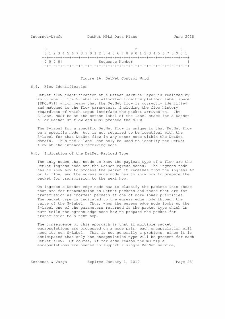
Internet-Draft DetNet MPLS Data Plane June 2018
0 1 2 3 0 1 2 3 4 5 6 7 8 9 0 1 2 3 4 5 6 7 8 9 0 1 2 3 4 5 6 7 8 9 0 1 +-+-+-+-+-+-+-+-+-+-+-+-+-+-+-+-+-+-+-+-+-+-+-+-+-+-+-+-+-+-+-+-+ |0 0 0 0| Sequence Number | +-+-+-+-+-+-+-+-+-+-+-+-+-+-+-+-+-+-+-+-+-+-+-+-+-+-+-+-+-+-+-+-+
Figure 16: DetNet Control Word
6.4. Flow Identification
DetNet flow identification at a DetNet service layer is realized by an S-label. The S-label is allocated from the platform label space [RFC3031] which means that the DetNet flow is correctly identified and matched to the flow parameters, including the flow history, regardless of which input interface the packet arrives on. The S-label MUST be at the bottom label of the label stack for a DetNet- s- or DetNet-st-flow and MUST precede the d-CW.
The S-label for a specific DetNet flow is unique to that DetNet flow on a specific node, but is not required to be identical with the S-label for that DetNet flow in any other node within the DetNet domain. Thus the S-label can only be used to identify the DetNet flow at the intended receiving node.
6.5. Indication of the DetNet Payload Type
The only nodes that needs to know the payload type of a flow are the DetNet ingress node and the DetNet egress nodes. The ingress node has to know how to process the packet it receives from the ingress AC or IP flow, and the egress edge node has to know how to prepare the packet for transmission to the next hop.
On ingress a DetNet edge node has to classify the packets into those that are for transmission as Detnet packets and those that are for transmission as "normal" packets at one of more lower priorities. The packet type is indicated to the egress edge node through the value of the S-label. Thus, when the egress edge node looks up the S-label one of the parameters returned is the packet type which in turn tells the egress edge node how to prepare the packet for transmission to a next hop.
The consequence of this approach is that if multiple packet encapsulations are processed on a node pair, each encapsulation will need its own S-Label. That is not generally a problems, since it is anticipated that only one encapsulation type will be present for each DetNet flow. Of course, if for some reason the multiple encapsulations are needed to support a single DetNet service,
Korhonen & Varga Expires January 1, 2019 [Page 23]

Internet-Draft DetNet MPLS Data Plane June 2018
multiple S-labels will be required for that service. Note that in the unlikely case that Ipv4 and IPv6 will map to the same DetNet flow, different S-labels will be needed to differentiate between the versions of IP.
6.6. OAM Indication
OAM follows the procedures set out in [RFC5085] with the restriction that only Virtual Circuit Connectivity Verification (VCCV) type 1 is supported.
As shown in Figure 3 of [RFC5085] when the first nibble of the d-CW is 0x0 the payload following the d-CW is normal user data. However, when the first nibble of the d-CW is 0X1, the payload that follows the d-DW is an OAM payload with the OAM type indicated by the value in the d-CW Channel Type field.
The reader is referred to [RFC5085] for a more detailed description of the Associated Channel mechanism, and to the DetNet work on OAM for more information DetNet OAM.
6.7. Flow Aggregation
1. Aggregate at the LSP (Transport)
2. Aggregating DetNet flows as a new DetNet flow
3. Simple Aggregation at the DetNet layer
A further method of using SR to perform aggregation is for further study.
The resource control and management aspects of aggregation (including the queuing/shaping/ policing implications) will be covered in other documents.
The ability to aggregate individual flows, and their associated resource control, into a larger aggregate is an important technique for improving scaling of control in the data, management and control planes. The DetNet data plane allows for the aggregation of DetNet flows, to improved scaling. There are three methods of introducing flow aggregation:
The following review comments were received when this section was committed to github.
General comment: We should points to the major issue of aggregation, namely the Seq.Num related problem. The aggregated flows have their
Korhonen & Varga Expires January 1, 2019 [Page 24]

Internet-Draft DetNet MPLS Data Plane June 2018
own Seq.Num and those are independent. We should consider to group the aggregation techniques as per their impact on what DetNet functions they allow on a DetNet flow. (E.g., aggregation without new Aggregate.Seq.Num would prohibit usage of FR, EF and in-order- delivery function on the aggregate flow).
SR based aggregation can be treated as a form of H-LSP aggregation. Should we differentiate them? What are the differences?
What are the issues when aggregating of different payload types? Should we add an editor note on this?
Simple-aggregation-at-the-detnet-layer: is this not the same as H-LSP? The A-label can be treated just as an additional T-label.
End of review comment.
6.7.1. Aggregation at the LSP
DetNet flows transported via MPLS can leverage MPLS-TE?s existing support for hierarchical LSPs (H-LSPs), see [RFC4206]. H-LSPs are typically used to aggregate control and resources, they may also be used to provide OAM or protection for the aggregated LSPs. Arbitrary levels of aggregation naturally falls out of the definition for hierarchy and the MPLS label stack [RFC3032]. DetNet nodes which support aggregation (LSP hierarchy) map one or more LSPs (labels) into and from an H-LSP. Both carried LSPs and H-LSPs may or may not use the TC field, i.e., L-LSPs or E-LSPs. Such nodes will need to ensure that traffic from aggregated LSPs are placed (shaped/policed/ enqueued) onto the H-LSPs in a fashion that ensures the required DetNet service is preserved.
Additional details of the traffic control capabilities needed at a DetNet-aware node may be covered in the new service descriptions mentioned above or in separate future documents. Management and control plane mechanisms will also need to ensure that the service required on the aggregate flow (H-LSP or DSCP) are provided, which may include the discarding or remarking mentioned in the previous sections.
6.7.2. Aggregating DetNet flows as a new DetNet flow
An aggregate can be built by layering DetNet flows as shown below:
Korhonen & Varga Expires January 1, 2019 [Page 25]

Internet-Draft DetNet MPLS Data Plane June 2018
+---------------------------------+ | | | DetNet Flow | | Payload Packet | | | +---------------------------------+ <--\ | DetNet Control Word | | +=================================+ | | S-Label | | +---------------------------------+ +----DetNet data plane | DetNet Control Word | | MPLS encapsulation +=================================+ | | A-Label | | +---------------------------------+ <--/ | T-Label(s) | +---------------------------------+ | Data-Link | +---------------------------------+ | Physical | +---------------------------------+
Both the Aggregation (A) label and the S-label have their MPLS S bit set indicating bottom of stack, and the d-CW allows the PREOF to work.
It is a property of the A-label that what follows is d-CW followed by an S-label. A relay node processing the A-label would not know the underlying payload type. This would only be known to a node that was a peer of the node imposing the S-label. However there is no real need for it to know the payload type during aggregation processing.
6.7.3. Simple Aggregation at the DetNet layer
Another approach would be not to include a d-CW for the aggregated flow. This would be functionally similar to aggregation at the transport layer using H-LSPs, but would confine knowledge of the aggregation to the DetNet layer. Such an approach shares the disadvantage that PREOF operations would not be possible. OAM operation in this mode is for further study.
Korhonen & Varga Expires January 1, 2019 [Page 26]

Internet-Draft DetNet MPLS Data Plane June 2018
+---------------------------------+ | | | DetNet Flow | | Payload Packet | | | +---------------------------------+ <--\ | DetNet Control Word | | +=================================+ | | S-Label | +----DetNet data plane +---------------------------------+ | MPLS encapsulation | A-Label | | +---------------------------------+ <--/ | T-Label(s) | +---------------------------------+ | Data-Link | +---------------------------------+ | Physical | +---------------------------------+
6.8. Service Layer Considerations
The edge and relay node internal procedures related to PREOF are implementation specific. The order of a packet elimination or replication is out of scope in this specification. However, care should be taken that the replication function does not actually loopback packets as "replicas". Looped back packets include artificial delay when the node that originally initiated the packet receives it again. Also, looped back packets may make the network condition to look healthier than it actually is (in some cases link failures are not reflected properly because looped back packets make the situation appear better than it actually is).
It is important that the DetNet layer is configured such that a DetNet node never receives its own replicated packets. If it were to receive such packets the replication function would make the loop more destructive of bandwidth than a conventional unicast loop. Ultimately the TTL in the S-Label will cause the packet to die during a transient, but given the sensitivity of applications to packet latency the impact on the DetNet application would be severe.
6.8.1. Edge node processing
An edge node is resposable for matching ingress packets to the service they require and encapsulating them accordingly.An edge node may participate in the packet replication and duplication elimination.
Korhonen & Varga Expires January 1, 2019 [Page 27]

Internet-Draft DetNet MPLS Data Plane June 2018
The DetNet-aware forwarder selects the egress DetNet member flow segment based on the flow identification. The mapping of ingress DetNet member flow segment to egress DetNet member flow segment may be statically or dynamically configured. Additionally the DetNet- aware forwarder does duplicate frame elimination based on the flow identification and the sequence number combination. The packet replication is also done within the DetNet-aware forwarder. During elimination and the replication process the sequence number of the DetNet member flow MUST be preserved and copied to the egress DetNet member flow.
The internal design of a relay node is out of scope of this document. However the reader’s attention is drawn to the need to make any PREOF state available to the packet processor(s) dealing with packets to which the PREOF functions must be applied, and to maintain that state is such as way that it is available to the packet processor operation on the next packet in the DetNet flow (which may be a duplicate, a late packet, or the next packet in sequence.
[Editor’s note: I think the rest of this section belongs in a new "802.1 TSN (island Interconnect) over MPLS DetNet" section.]
This may be done in the DetNet layer, or where the native service processing (NSP) [RFC3985] is IEEE 802.1CB [IEEE8021CB] capable, the packet replication and duplicate elimination MAY entirely be done in the NSP, bypassing the DetNet flow encapsulation and logic entirely. This enables operating over unmodified implementations and deployments. The NSP approach works only between edge nodes and cannot make use of relay nodes.
The NSP approach is useful end to end tunnel and for for "island interconnect" scenarios. However, when there is a need to do PREOF in a middle of the network, such plain edge to edge operation is not sufficient.
The extended forwarder MAY copy the sequencing information from the native DetNet packet into the DetNet sequence number field and vice versa. If there is no existing sequencing information available in the native packet or the forwarder chose not to copy it from the native packet, then the extended forwarder MUST maintain a sequence number counter for each DetNet flow (indexed by the DetNet flow identification).
6.8.2. Relay node processing
A DetNet Relay node operates in the DetNet transport layer . This processing is done within an extended forwarder function. Whether an ingress DetNet member flow receives DetNet specific processing
Korhonen & Varga Expires January 1, 2019 [Page 28]
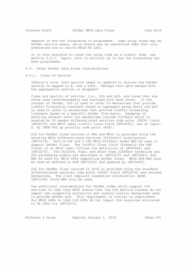
Internet-Draft DetNet MPLS Data Plane June 2018
depends on how the forwarding is programmed. Some relay nodes may be DetNet service aware, while others may be unmodified LSRs that only understand how to swicth MPLS-TE LSPs.
It is also possible to treat the relay node as a transit node, see Section 6.9.3. Again, this is entirely up to how the forwarding has been programmed.
6.9. Other DetNet data plane considerations
6.9.1. Class of Service
[Editor’s note: this section needs to updated to discuss how DetNet service is mapped to E- and L-LSPs. Perhaps this gets merged with the aggregation section or dropped?]
Class and quality of service, i.e., CoS and QoS, are terms that are often used interchangeably and confused with each other. In the context of DetNet, CoS is used to refer to mechanisms that provide traffic forwarding treatment based on aggregate group basis and QoS is used to refer to mechanisms that provide traffic forwarding treatment based on a specific DetNet flow basis. Examples of existing network level CoS mechanisms include DiffServ which is enabled by IP header differentiated services code point (DSCP) field [RFC2474] and MPLS label traffic class field [RFC5462], and at Layer- 2, by IEEE 802.1p priority code point (PCP).
CoS for DetNet flows carried in PWs and MPLS is provided using the existing MPLS Differentiated Services (DiffServ) architecture [RFC3270]. Both E-LSP and L-LSP MPLS DiffServ modes MAY be used to support DetNet flows. The Traffic Class field (formerly the EXP field) of an MPLS label follows the definition of [RFC5462] and [RFC3270]. The Uniform, Pipe, and Short Pipe DiffServ tunneling and TTL processing models are described in [RFC3270] and [RFC3443] and MAY be used for MPLS LSPs supporting DetNet flows. MPLS ECN MAY also be used as defined in ECN [RFC5129] and updated by [RFC5462].
CoS for DetNet flows carried in IPv6 is provided using the standard differentiated services code point (DSCP) field [RFC2474] and related mechanisms. The 2-bit explicit congestion notification (ECN) [RFC3168] field MAY also be used.
One additional consideration for DetNet nodes which support CoS services is that they MUST ensure that the CoS service classes do not impact the congestion protection and latency control mechanisms used to provide DetNet QoS. This requirement is similar to requirement for MPLS LSRs to that CoS LSPs do not impact the resources allocated to TE LSPs via [RFC3473].
Korhonen & Varga Expires January 1, 2019 [Page 29]

Internet-Draft DetNet MPLS Data Plane June 2018
6.9.2. Quality of Service
Quality of Service (QoS) mechanisms for flow specific traffic treatment typically includes a guarantee/agreement for the service, and allocation of resources to support the service. Example QoS mechanisms include discrete resource allocation, admission control, flow identification and isolation, and sometimes path control, traffic protection, shaping, policing and remarking. Example protocols that support QoS control include Resource ReSerVation Protocol (RSVP) [RFC2205] (RSVP) and RSVP-TE [RFC3209] and [RFC3473]. The existing MPLS mechanisms defined to support CoS [RFC3270] can also be used to reserve resources for specific traffic classes.
In addition to explicit routes, and packet replication and elimination, described in Section 6 above, DetNet provides zero congestion loss and bounded latency and jitter. As described in [I-D.ietf-detnet-architecture], there are different mechanisms that maybe used separately or in combination to deliver a zero congestion loss service. These mechanisms are provided by the either the MPLS or IP layers, and may be combined with the mechanisms defined by the underlying network layer such as 802.1TSN.
A baseline set of QoS capabilities for DetNet flows carried in PWs and MPLS can provided by MPLS with Traffic Engineering (MPLS-TE) [RFC3209] and [RFC3473]. TE LSPs can also support explicit routes (path pinning). Current service definitions for packet TE LSPs can be found in "Specification of the Controlled Load Quality of Service", [RFC2211], "Specification of Guaranteed Quality of Service", [RFC2212], and "Ethernet Traffic Parameters", [RFC6003]. Additional service definitions are expected in future documents to support the full range of DetNet services. In all cases, the existing label-based marking mechanisms defined for TE-LSPs and even E-LSPs are use to support the identification of flows requiring DetNet QoS.
Packets that are marked with a DetNet Class of Service value, but that have not been the subject of a completed reservation, can disrupt the QoS offered to properly reserved DetNet flows by using resources allocated to the reserved flows. Therefore, the network nodes of a DetNet network:
o MUST defend the DetNet QoS by discarding or remarking (to a non- DetNet CoS) packets received that are not the subject of a completed reservation.
o MUST NOT use a DetNet reserved resource, e.g. a queue or shaper reserved for DetNet flows, for any packet that does not carry a DetNet Class of Service marker.
Korhonen & Varga Expires January 1, 2019 [Page 30]

Internet-Draft DetNet MPLS Data Plane June 2018
6.9.3. Cross-DetNet flow resource aggregation
[Editor’s NOTE: keep and extend this section.]
The ability to aggregate individual flows, and their associated resource control, into a larger aggregate is an important technique for improving scaling of control in the data, management and control planes. This document identifies the traffic identification related aspects of aggregation of DetNet flows. The resource control and management aspects of aggregation (including the queuing/shaping/ policing implications) will be covered in other documents. The data plane implications of aggregation are independent for PW/MPLS and IP encapsulated DetNet flows.
DetNet flows transported via MPLS can leverage MPLS-TE’s existing support for hierarchical LSPs (H-LSPs), see [RFC4206]. H-LSPs are typically used to aggregate control and resources, they may also be used to provide OAM or protection for the aggregated LSPs. Arbitrary levels of aggregation naturally falls out of the definition for hierarchy and the MPLS label stack [RFC3032]. DetNet nodes which support aggregation (LSP hierarchy) map one or more LSPs (labels) into and from an H-LSP. Both carried LSPs and H-LSPs may or may not use the TC field, i.e., L-LSPs or E-LSPs. Such nodes will need to ensure that traffic from aggregated LSPs are placed (shaped/policed/ enqueued) onto the H-LSPs in a fashion that ensures the required DetNet service is preserved.
DetNet flows transported via IP have more limited aggregation options, due to the available traffic flow identification fields of the IP solution. One available approach is to manage the resources associated with a DSCP identified traffic class and to map (remark) individually controlled DetNet flows onto that traffic class. This approach also requires that nodes support aggregation ensure that traffic from aggregated LSPs are placed (shaped/policed/enqueued) in a fashion that ensures the required DetNet service is preserved.
In both the MPLS and IP cases, additional details of the traffic control capabilities needed at a DetNet-aware node may be covered in the new service descriptions mentioned above or in separate future documents. Management and control plane mechanisms will also need to ensure that the service required on the aggregate flow (H-LSP or DSCP) are provided, which may include the discarding or remarking mentioned in the previous sections.
Korhonen & Varga Expires January 1, 2019 [Page 31]
Internet-Draft DetNet MPLS Data Plane June 2018
6.9.4. Layer 2 addressing and QoS Considerations
[Editor’s NOTE: review and simplify this section.]
The Time-Sensitive Networking (TSN) Task Group of the IEEE 802.1 Working Group have defined (and are defining) a number of amendments to IEEE 802.1Q [IEEE8021Q] that provide zero congestion loss and bounded latency in bridged networks. IEEE 802.1CB [IEEE8021CB] defines packet replication and elimination functions that should prove both compatible with and useful to, DetNet networks.
As is the case for DetNet, a Layer 2 network node such as a bridge may need to identify the specific DetNet flow to which a packet belongs in order to provide the TSN/DetNet QoS for that packet. It also will likely need a CoS marking, such as the priority field of an IEEE Std 802.1Q VLAN tag, to give the packet proper service.
Although the flow identification methods described in IEEE 802.1CB [IEEE8021CB] are flexible, and in fact, include IP 5-tuple identification methods, the baseline TSN standards assume that every Ethernet frame belonging to a TSN stream (i.e. DetNet flow) carries a multicast destination MAC address that is unique to that flow within the bridged network over which it is carried. Furthermore, IEEE 802.1CB [IEEE8021CB] describes three methods by which a packet sequence number can be encoded in an Ethernet frame.
Ensuring that the proper Ethernet VLAN tag priority and destination MAC address are used on a DetNet/TSN packet may require further clarification of the customary L2/L3 transformations carried out by routers and edge label switches. Edge nodes may also have to move sequence number fields among Layer 2, PW, and IPv6 encapsulations.
6.9.5. Time Synchronization
[Editor’s Note: A detailed discussion of time synchronization is outside the scope of this document, and the production of a specialist text discussing this topic is encouraged. This section will be updated/removed if such a document is available before publication of this text.]
Time synchronization is important both from the perspective of operating the DetNet network itself and from the perspective of transferring time across the network between client applications. Some clients may be able to use the DetNet as their provider of time and frequency, others may require the DetNet to transfer time between a client clock source and a client clock user.
Korhonen & Varga Expires January 1, 2019 [Page 32]

Internet-Draft DetNet MPLS Data Plane June 2018
The reader’s attention is drawn to [RFC8169] which describes a method of recording the packet queuing time in an MPLS LSR on a packet by per packet basis and forwarding this information to the egress edge system. This allows compensation for any variable packet queuing delay to be applied at the packet receiver. The mechanism described in [RFC8169] may have wider application than basic time transfer in a DetNet.
A more detailed discussion of time synchronization is outside the scope of this document.
7. Management and control considerations
[Editor’s note: This section needs to be different for MPLS and IP solutions. Most solutions are technology dependant. Currently most text in this section is just a draft and may have bits that are already moved to other places/documents.]
While management plane and control planes are traditionally considered separately, from the Data Plane perspective there is no practical difference based on the origin of flow provisioning information. This document therefore does not distinguish between information provided by a control plane protocol, e.g., RSVP-TE [RFC3209] and [RFC3473], or by a network management mechanisms, e.g., RestConf [RFC8040] and YANG [RFC7950].
[Editor’s note: This section is a work in progress. discuss here what kind of enhancements are needed for DetNet and specifically for PREOF and DetNet zero congest loss and latency control. Need to cover both traffic control (queuing) and connection control (control plane).]
7.1. MPLS-based data plane
7.1.1. S-Label assignment and distribution
[Editor’s note: Outdated and needs more work.]
The DetNet S-Label distribution follows the same mechanisms specified for XYZ . The details of the control plane protocol solution required for the label distribution and the management of the label number space are out of scope of this document.
7.1.2. Explicit routes
It is necessary to consider explicit routes both at the DetNet layer and in the MPLS layer. In the DetNet layer the explicit route consists of the set of Relay Nodes that the DetNet flow must
Korhonen & Varga Expires January 1, 2019 [Page 33]

Internet-Draft DetNet MPLS Data Plane June 2018
traverse. In the MPLS layer the explicit route consists of the set of LSRs, links, and possibly link bundle members and queues that the DetNet packets of a flow must traverse between nodes in the DetNet layer (i.e. between a specific Edge Node and the next hop Relay Node, between specific Relay Nodes, and between a specific Relay node and the egress Edge Node. This detailed steering is needed to ensure that packets are routed through the resources that have been reserved for them, and hence provide the DetNet application with the required performance.
Whether configuring, calculating and instantiating this is a multi- stage process, or a single stage process is out of scope of this document.
The one method of explicitly setting up the explicit path at the DetNet layer is through the use of the management controller.
[Editor’s note: a method of setting up a graph through the DetNet Nodes using the IGP has been proposed. A reference is needed to e.g., RFC 7813 IS-IS Path Control and Reservation.]
There are a number of approaches that can be taken to provide explicit routes/paths in the MPLS layer:
o The path can be explicitly set up by the management controller calculating the path and explicitly configuring each node along that path.
o The LSP can be set up using RSVP-TE. Such an approach confines the packet to the explicit path.
o The path can be implemented using segment routing.
Where the DetNet traffic is carried over IP Section 11 explicit paths may need to be provided in the IP layer. This is for further study.
7.2. Packet replication and elimination
[Editor’s note: Outdated and at the functional level technology independent.. but needs more work.]
The control plane protocol solution required for managing the PREOF processing is outside the scope of this document.
Korhonen & Varga Expires January 1, 2019 [Page 34]

Internet-Draft DetNet MPLS Data Plane June 2018
7.3. Congestion protection and latency control
[Editor’s note: TBD]
7.4. Bidirectional traffic
[Editor’s NOTE: this section needs to be updated to have its scope limited to management and control.]
Some DetNet applications generate bidirectional traffic. Using MPLS definitions [RFC5654] there are associated bidirectional flows, and co-routed bidirectional flows. MPLS defines a point-to-point associated bidirectional LSP as consisting of two unidirectional point-to-point LSPs, one from A to B and the other from B to A, which are regarded as providing a single logical bidirectional transport path. This would be analogous of standard IP routing, or PWs running over two reciprocal unidirection LSPs. MPLS defines a point-to-point co-routed bidirectional LSP as an associated bidirectional LSP which satisfies the additional constraint that its two unidirectional component LSPs follow the same path (in terms of both nodes and links) in both directions. An important property of co-routed bidirectional LSPs is that their unidirectional component LSPs share fate. In both types of bidirectional LSPs, resource allocations may differ in each direction. The concepts of associated bidirectional flows and co-routed bidirectional flows can be applied to DetNet flows as well whether IPv6 or MPLS is used.
While the IPv6 and MPLS data planes must support bidirectional DetNet flows, there are no special bidirectional features with respect to the data plane other than need for the two directions take the same paths. Fate sharing and associated vs co-routed bidirectional flows can be managed at the control level. Note, that there is no stated requirement for bidirectional DetNet flows to be supported using the same IPv6 Flow Labels or MPLS Labels in each direction. Control mechanisms will need to support such bidirectional flows for both IPv6 and MPLS, but such mechanisms are out of scope of this document. An example control plane solution for MPLS can be found in [RFC7551].
7.5. Flow aggregation control
[TBD]
8. DetNet IP Operation over DetNet MPLS Service
[Editor’s note: this is a place holder section. A standalone section on operation of IP flows over DetNet MPLS data plane. Includes RFC2119 Language.]
Korhonen & Varga Expires January 1, 2019 [Page 35]

Internet-Draft DetNet MPLS Data Plane June 2018
9. IEEE 802.1 TSN Interconnection over DetNet MPLS Service
[Editor’s note: this is a place holder section. A standalone section on TSN "island" interconnect over DetNet". Includes RFC2119 Language.]
10. DetNet MPLS Transport Layer Operation over IEEE 802.1 TSN Sub- Networks
[Editor’s note: this is a place holder section. A standalone section on MPLS over IEEE 802.1 TSN. Includes RFC2119 Language.]
11. DetNet MPLS Transport Layer Operation over IP DetNet PSNs
This section specifies the DetNet encapsulation over an IP transport network. The approach is modeled on the operation of MPLS and PseudoWires (PW) over an IP Packet Switched Network (PSN) [RFC3985][RFC4385][RFC7510]. It is also based on the MPLS data plane encapsulation described in Section 6.2.
To carry DetNet with full functionality at the DetNet layer over an IP transport network, the following components are required (these are a subset of the requirements for MPLS encapsulation listed in Section 6.1):
1. A method of identifying the DetNet flow group to the processing element.
2. A method of carrying the DetNet sequence number.
3. A method of distinguishing DetNet OAM packets from DetNet data packets.
4. A method of carrying queuing and forwarding indication.
These requirements are satisfied by the DetNet over MPLS Encapsulation described in Section 6.2.
To simplify operations and implementations, rather than inventing a new encapsulation, the IP encapsulation takes advantage of the MPLS encapsulation. By using the specification of MPLS over UDP and IP in [RFC7510], the T-Label(s) shown in Figure 15 in Section 6.2 can be replaced by UDP and IP, resulting in the following encapsulation:
Korhonen & Varga Expires January 1, 2019 [Page 36]

Internet-Draft DetNet MPLS Data Plane June 2018
+---------------------------------+ | | | DetNet Flow | | Payload Packet | | | +---------------------------------+ <--\ | DetNet Control Word | | +---------------------------------+ +--> DetNet data plane | S-Label | | MPLS encapsulation +---------------------------------+ <--/ | UDP Header | +---------------------------------+ | IP Header | +---------------------------------+ | Data-Link | +---------------------------------+ | Physical | +---------------------------------+
Figure 17: IP Encapsulation of DetNet
Where the UDP header is used as defined in Section 3 of [RFC7510].
As in Section 6.2, the S-Label is used to identify a DetNet flow to the peer node that processes it, in this case the node addressed by the IP Header in Figure 17. The S-Label is allocated from the receiving node?s platform label space [RFC3031].
In ingress Edge Nodes, the encapsulation in Figure 17 will be imposed on Detnet Flow Payload Packets as received from DetNet End Systems, and the encapsulation will be removed in egress Edge Nodes as they transmit the Payload Packets to the End Systems.
Note that this encapsulation works equally well with IPv4 and IPv6.
This encapsulation can also be used in conjunction with segment routing as specified in [I-D.ietf-spring-segment-routing-mpls]. In this case, the T-Label(s) in Figure 17 should be retained, and at each hop, the top T-label is popped and mapped to a corresponding UDP/IP tunnel, resulting in the following encapsulation:
Korhonen & Varga Expires January 1, 2019 [Page 37]

Internet-Draft DetNet MPLS Data Plane June 2018
+---------------------------------+ | | | DetNet Flow | | Payload Packet | | | +---------------------------------+ <--\ | DetNet Control Word | | +---------------------------------+ +--> DetNet data plane | S-Label | | MPLS encapsulation +---------------------------------+ <--/ | T-Label(s) | +---------------------------------+ | UDP Header | +---------------------------------+ | IP Header | +---------------------------------+ | Data-Link | +---------------------------------+ | Physical | +---------------------------------+
Figure 18: IP Encapsulation of DetNet with MPLS-SR
Again, the UDP header is used as defined in Section 3 of [RFC7510].
Note that if required in both the case of IP Encapsulation of DetNet Figure 17, and of IP Encapsulation of DetNet with MPLS-SR Figure 18, it is possible to omit the UDP header if required. Operation of MPLS directly over IP is described in [RFC4023]. In this case DetNet Service can be provided on a per IP flow basis as described in [I-D.ietf-detnet-dp-sol-ip].
12. Security considerations
The security considerations of DetNet in general are discussed in [I-D.ietf-detnet-architecture] and [I-D.sdt-detnet-security]. Other security considerations will be added in a future version of this draft.
13. IANA considerations
This document makes no IANA requests.
Korhonen & Varga Expires January 1, 2019 [Page 38]

Internet-Draft DetNet MPLS Data Plane June 2018
14. Contributors
RFC7322 limits the number of authors listed on the front page of a draft to a maximum of 5, far fewer than the 20 individuals below who made important contributions to this draft. The editor wishes to thank and acknowledge each of the following authors for contributing text to this draft. See also Section 15.
Korhonen & Varga Expires January 1, 2019 [Page 39]

Internet-Draft DetNet MPLS Data Plane June 2018
Loa Andersson Huawei Email: [email protected]
Yuanlong Jiang Huawei Email: [email protected]
Norman Finn Huawei 3101 Rio Way Spring Valley, CA 91977 USA Email: [email protected]
Janos Farkas Ericsson Magyar Tudosok krt. 11. Budapest 1117 Hungary Email: [email protected]
Carlos J. Bernardos Universidad Carlos III de Madrid Av. Universidad, 30 Leganes, Madrid 28911 Spain Email: [email protected]
Tal Mizrahi Marvell 6 Hamada st. Yokneam Israel Email: [email protected]
Lou Berger LabN Consulting, L.L.C. Email: [email protected]
Stewart Bryant Huawei Technologies Email: [email protected]
Mach Chen Huawei Technologies Email: [email protected]
Korhonen & Varga Expires January 1, 2019 [Page 40]

Internet-Draft DetNet MPLS Data Plane June 2018
15. Acknowledgements
The author(s) ACK and NACK.
The following people were part of the DetNet Data Plane Solution Design Team:
Jouni Korhonen
Janos Farkas
Norman Finn
Balazs Varga
Loa Andersson
Tal Mizrahi
David Mozes
Yuanlong Jiang
Carlos J. Bernardos
The DetNet chairs serving during the DetNet Data Plane Solution Design Team:
Lou Berger
Pat Thaler
Thanks for Stewart Bryant for his extensive review of the previous versions of the document.
16. References
16.1. Normative references
[I-D.ietf-spring-segment-routing-mpls] Bashandy, A., Filsfils, C., Previdi, S., Decraene, B., Litkowski, S., and R. Shakir, "Segment Routing with MPLS data plane", draft-ietf-spring-segment-routing-mpls-14 (work in progress), June 2018.
Korhonen & Varga Expires January 1, 2019 [Page 41]

Internet-Draft DetNet MPLS Data Plane June 2018
[RFC2119] Bradner, S., "Key words for use in RFCs to Indicate Requirement Levels", BCP 14, RFC 2119, DOI 10.17487/RFC2119, March 1997, <https://www.rfc-editor.org/info/rfc2119>.
[RFC2211] Wroclawski, J., "Specification of the Controlled-Load Network Element Service", RFC 2211, DOI 10.17487/RFC2211, September 1997, <https://www.rfc-editor.org/info/rfc2211>.
[RFC2212] Shenker, S., Partridge, C., and R. Guerin, "Specification of Guaranteed Quality of Service", RFC 2212, DOI 10.17487/RFC2212, September 1997, <https://www.rfc-editor.org/info/rfc2212>.
[RFC2474] Nichols, K., Blake, S., Baker, F., and D. Black, "Definition of the Differentiated Services Field (DS Field) in the IPv4 and IPv6 Headers", RFC 2474, DOI 10.17487/RFC2474, December 1998, <https://www.rfc-editor.org/info/rfc2474>.
[RFC3031] Rosen, E., Viswanathan, A., and R. Callon, "Multiprotocol Label Switching Architecture", RFC 3031, DOI 10.17487/RFC3031, January 2001, <https://www.rfc-editor.org/info/rfc3031>.
[RFC3032] Rosen, E., Tappan, D., Fedorkow, G., Rekhter, Y., Farinacci, D., Li, T., and A. Conta, "MPLS Label Stack Encoding", RFC 3032, DOI 10.17487/RFC3032, January 2001, <https://www.rfc-editor.org/info/rfc3032>.
[RFC3168] Ramakrishnan, K., Floyd, S., and D. Black, "The Addition of Explicit Congestion Notification (ECN) to IP", RFC 3168, DOI 10.17487/RFC3168, September 2001, <https://www.rfc-editor.org/info/rfc3168>.
[RFC3209] Awduche, D., Berger, L., Gan, D., Li, T., Srinivasan, V., and G. Swallow, "RSVP-TE: Extensions to RSVP for LSP Tunnels", RFC 3209, DOI 10.17487/RFC3209, December 2001, <https://www.rfc-editor.org/info/rfc3209>.
[RFC3270] Le Faucheur, F., Wu, L., Davie, B., Davari, S., Vaananen, P., Krishnan, R., Cheval, P., and J. Heinanen, "Multi- Protocol Label Switching (MPLS) Support of Differentiated Services", RFC 3270, DOI 10.17487/RFC3270, May 2002, <https://www.rfc-editor.org/info/rfc3270>.
Korhonen & Varga Expires January 1, 2019 [Page 42]

Internet-Draft DetNet MPLS Data Plane June 2018
[RFC3443] Agarwal, P. and B. Akyol, "Time To Live (TTL) Processing in Multi-Protocol Label Switching (MPLS) Networks", RFC 3443, DOI 10.17487/RFC3443, January 2003, <https://www.rfc-editor.org/info/rfc3443>.
[RFC3473] Berger, L., Ed., "Generalized Multi-Protocol Label Switching (GMPLS) Signaling Resource ReserVation Protocol- Traffic Engineering (RSVP-TE) Extensions", RFC 3473, DOI 10.17487/RFC3473, January 2003, <https://www.rfc-editor.org/info/rfc3473>.
[RFC4023] Worster, T., Rekhter, Y., and E. Rosen, Ed., "Encapsulating MPLS in IP or Generic Routing Encapsulation (GRE)", RFC 4023, DOI 10.17487/RFC4023, March 2005, <https://www.rfc-editor.org/info/rfc4023>.
[RFC4206] Kompella, K. and Y. Rekhter, "Label Switched Paths (LSP) Hierarchy with Generalized Multi-Protocol Label Switching (GMPLS) Traffic Engineering (TE)", RFC 4206, DOI 10.17487/RFC4206, October 2005, <https://www.rfc-editor.org/info/rfc4206>.
[RFC4385] Bryant, S., Swallow, G., Martini, L., and D. McPherson, "Pseudowire Emulation Edge-to-Edge (PWE3) Control Word for Use over an MPLS PSN", RFC 4385, DOI 10.17487/RFC4385, February 2006, <https://www.rfc-editor.org/info/rfc4385>.
[RFC5085] Nadeau, T., Ed. and C. Pignataro, Ed., "Pseudowire Virtual Circuit Connectivity Verification (VCCV): A Control Channel for Pseudowires", RFC 5085, DOI 10.17487/RFC5085, December 2007, <https://www.rfc-editor.org/info/rfc5085>.
[RFC5129] Davie, B., Briscoe, B., and J. Tay, "Explicit Congestion Marking in MPLS", RFC 5129, DOI 10.17487/RFC5129, January 2008, <https://www.rfc-editor.org/info/rfc5129>.
[RFC5462] Andersson, L. and R. Asati, "Multiprotocol Label Switching (MPLS) Label Stack Entry: "EXP" Field Renamed to "Traffic Class" Field", RFC 5462, DOI 10.17487/RFC5462, February 2009, <https://www.rfc-editor.org/info/rfc5462>.
[RFC6003] Papadimitriou, D., "Ethernet Traffic Parameters", RFC 6003, DOI 10.17487/RFC6003, October 2010, <https://www.rfc-editor.org/info/rfc6003>.
Korhonen & Varga Expires January 1, 2019 [Page 43]

Internet-Draft DetNet MPLS Data Plane June 2018
[RFC7510] Xu, X., Sheth, N., Yong, L., Callon, R., and D. Black, "Encapsulating MPLS in UDP", RFC 7510, DOI 10.17487/RFC7510, April 2015, <https://www.rfc-editor.org/info/rfc7510>.
[RFC8174] Leiba, B., "Ambiguity of Uppercase vs Lowercase in RFC 2119 Key Words", BCP 14, RFC 8174, DOI 10.17487/RFC8174, May 2017, <https://www.rfc-editor.org/info/rfc8174>.
16.2. Informative references
[I-D.ietf-detnet-architecture] Finn, N., Thubert, P., Varga, B., and J. Farkas, "Deterministic Networking Architecture", draft-ietf- detnet-architecture-05 (work in progress), May 2018.
[I-D.ietf-detnet-dp-alt] Korhonen, J., Farkas, J., Mirsky, G., Thubert, P., Zhuangyan, Z., and L. Berger, "DetNet Data Plane Protocol and Solution Alternatives", draft-ietf-detnet-dp-alt-00 (work in progress), October 2016.
[I-D.ietf-detnet-dp-sol-ip] Korhonen, J., Varga, B., "DetNet IP Data Plane Encapsulation", 2018.
[I-D.sdt-detnet-security] Mizrahi, T., Grossman, E., Hacker, A., Das, S., "Deterministic Networking (DetNet) Security Considerations, draft-sdt-detnet-security, work in progress", 2017.
[IEEE8021CB] Finn, N., "Draft Standard for Local and metropolitan area networks - Seamless Redundancy", IEEE P802.1CB /D2.1 P802.1CB, December 2015, <http://www.ieee802.org/1/files/private/cb-drafts/ d2/802-1CB-d2-1.pdf>.
[IEEE8021Q] IEEE 802.1, "Standard for Local and metropolitan area networks--Bridges and Bridged Networks (IEEE Std 802.1Q- 2014)", 2014, <http://standards.ieee.org/about/get/>.
[RFC2205] Braden, R., Ed., Zhang, L., Berson, S., Herzog, S., and S. Jamin, "Resource ReSerVation Protocol (RSVP) -- Version 1 Functional Specification", RFC 2205, DOI 10.17487/RFC2205, September 1997, <https://www.rfc-editor.org/info/rfc2205>.
Korhonen & Varga Expires January 1, 2019 [Page 44]

Internet-Draft DetNet MPLS Data Plane June 2018
[RFC3985] Bryant, S., Ed. and P. Pate, Ed., "Pseudo Wire Emulation Edge-to-Edge (PWE3) Architecture", RFC 3985, DOI 10.17487/RFC3985, March 2005, <https://www.rfc-editor.org/info/rfc3985>.
[RFC4448] Martini, L., Ed., Rosen, E., El-Aawar, N., and G. Heron, "Encapsulation Methods for Transport of Ethernet over MPLS Networks", RFC 4448, DOI 10.17487/RFC4448, April 2006, <https://www.rfc-editor.org/info/rfc4448>.
[RFC5654] Niven-Jenkins, B., Ed., Brungard, D., Ed., Betts, M., Ed., Sprecher, N., and S. Ueno, "Requirements of an MPLS Transport Profile", RFC 5654, DOI 10.17487/RFC5654, September 2009, <https://www.rfc-editor.org/info/rfc5654>.
[RFC5921] Bocci, M., Ed., Bryant, S., Ed., Frost, D., Ed., Levrau, L., and L. Berger, "A Framework for MPLS in Transport Networks", RFC 5921, DOI 10.17487/RFC5921, July 2010, <https://www.rfc-editor.org/info/rfc5921>.
[RFC6073] Martini, L., Metz, C., Nadeau, T., Bocci, M., and M. Aissaoui, "Segmented Pseudowire", RFC 6073, DOI 10.17487/RFC6073, January 2011, <https://www.rfc-editor.org/info/rfc6073>.
[RFC7551] Zhang, F., Ed., Jing, R., and R. Gandhi, Ed., "RSVP-TE Extensions for Associated Bidirectional Label Switched Paths (LSPs)", RFC 7551, DOI 10.17487/RFC7551, May 2015, <https://www.rfc-editor.org/info/rfc7551>.
[RFC7950] Bjorklund, M., Ed., "The YANG 1.1 Data Modeling Language", RFC 7950, DOI 10.17487/RFC7950, August 2016, <https://www.rfc-editor.org/info/rfc7950>.
[RFC8040] Bierman, A., Bjorklund, M., and K. Watsen, "RESTCONF Protocol", RFC 8040, DOI 10.17487/RFC8040, January 2017, <https://www.rfc-editor.org/info/rfc8040>.
[RFC8169] Mirsky, G., Ruffini, S., Gray, E., Drake, J., Bryant, S., and A. Vainshtein, "Residence Time Measurement in MPLS Networks", RFC 8169, DOI 10.17487/RFC8169, May 2017, <https://www.rfc-editor.org/info/rfc8169>.
Appendix A. Example of DetNet data plane operation
[Editor’s note: Add a simplified example of DetNet data plane and how labels etc work in the case of MPLS-based PSN and utilizing PREOF.
Korhonen & Varga Expires January 1, 2019 [Page 45]

Internet-Draft DetNet MPLS Data Plane June 2018
The figure is subject to change depending on the further DT decisions on the label handling..]
Authors’ Addresses
Jouni Korhonen (editor)
Email: [email protected]
Balazs Varga (editor) Ericsson Magyar Tudosok krt. 11. Budapest 1117 Hungary
Email: [email protected]
Korhonen & Varga Expires January 1, 2019 [Page 46]

DetNet J. FarkasInternet-Draft B. VargaIntended status: Standards Track EricssonExpires: September 6, 2018 R. Cummings National Instruments Y. Jiang Huawei Y. Zha Tencent March 05, 2018
DetNet Flow Information Model draft-ietf-detnet-flow-information-model-01
Abstract
This document describes flow and service information model for Deterministic Networking (DetNet). The DetNet service is provided either for a Layer 3 or a Layer 2 flow. This document provides DetNet flow and service information model both for Layer 3 and Layer 2 flows in an integrated fashion.
Status of This Memo
This Internet-Draft is submitted in full conformance with the provisions of BCP 78 and BCP 79.
Internet-Drafts are working documents of the Internet Engineering Task Force (IETF). Note that other groups may also distribute working documents as Internet-Drafts. The list of current Internet- Drafts is at https://datatracker.ietf.org/drafts/current/.
Internet-Drafts are draft documents valid for a maximum of six months and may be updated, replaced, or obsoleted by other documents at any time. It is inappropriate to use Internet-Drafts as reference material or to cite them other than as "work in progress."
This Internet-Draft will expire on September 6, 2018.
Copyright Notice
Copyright (c) 2018 IETF Trust and the persons identified as the document authors. All rights reserved.
This document is subject to BCP 78 and the IETF Trust’s Legal Provisions Relating to IETF Documents (https://trustee.ietf.org/license-info) in effect on the date of
Farkas, et al. Expires September 6, 2018 [Page 1]

Internet-Draft DetNet Flow Information Model March 2018
publication of this document. Please review these documents carefully, as they describe your rights and restrictions with respect to this document. Code Components extracted from this document must include Simplified BSD License text as described in Section 4.e of the Trust Legal Provisions and are provided without warranty as described in the Simplified BSD License.
Table of Contents
1. Introduction . . . . . . . . . . . . . . . . . . . . . . . . 3 1.1. Goals . . . . . . . . . . . . . . . . . . . . . . . . . . 4 1.2. Non Goals . . . . . . . . . . . . . . . . . . . . . . . . 5 2. Conventions Used in This Document . . . . . . . . . . . . . . 5 3. Terminology and Definitions . . . . . . . . . . . . . . . . . 5 4. Naming Conventions . . . . . . . . . . . . . . . . . . . . . 5 5. Service model . . . . . . . . . . . . . . . . . . . . . . . . 6 5.1. Service overview . . . . . . . . . . . . . . . . . . . . 6 5.2. Service parameters . . . . . . . . . . . . . . . . . . . 6 5.3. Reference Points . . . . . . . . . . . . . . . . . . . . 7 5.4. Service scenarios . . . . . . . . . . . . . . . . . . . . 8 6. End System and DetNet domain . . . . . . . . . . . . . . . . 8 7. Flow . . . . . . . . . . . . . . . . . . . . . . . . . . . . 10 7.1. Identification and Specification of Flows . . . . . . . . 11 7.1.1. DetNet L3 Flow Identification and Specification at UNI . . . . . . . . . . . . . . . . . . . . . . . . . 11 7.1.2. DetNet L2 Flow Identification and Specification at UNI . . . . . . . . . . . . . . . . . . . . . . . . . 11 7.1.3. DetNetwork Flow Identification and Specification . . 12 7.2. Traffic Specification . . . . . . . . . . . . . . . . . . 12 7.3. Flow Rank . . . . . . . . . . . . . . . . . . . . . . . . 14 7.4. Service Rank . . . . . . . . . . . . . . . . . . . . . . 14 8. Source . . . . . . . . . . . . . . . . . . . . . . . . . . . 14 9. Destination . . . . . . . . . . . . . . . . . . . . . . . . . 15 10. Common Attributes of Source and Destination . . . . . . . . . 16 10.1. End System Interfaces . . . . . . . . . . . . . . . . . 16 10.2. Interface Capabilities . . . . . . . . . . . . . . . . . 16 10.3. User to Network Requirements . . . . . . . . . . . . . . 17 11. Ingress . . . . . . . . . . . . . . . . . . . . . . . . . . . 18 12. Egress . . . . . . . . . . . . . . . . . . . . . . . . . . . 18 13. DetNet Domain . . . . . . . . . . . . . . . . . . . . . . . . 18 13.1. DetNet Domain Capabilities . . . . . . . . . . . . . . . 18 14. Flow-status . . . . . . . . . . . . . . . . . . . . . . . . . 19 14.1. Status Info . . . . . . . . . . . . . . . . . . . . . . 20 14.2. Interface Configuration . . . . . . . . . . . . . . . . 21 14.3. Failed Interfaces . . . . . . . . . . . . . . . . . . . 21 15. Service-status . . . . . . . . . . . . . . . . . . . . . . . 21 16. Summary . . . . . . . . . . . . . . . . . . . . . . . . . . . 21 17. IANA Considerations . . . . . . . . . . . . . . . . . . . . . 22
Farkas, et al. Expires September 6, 2018 [Page 2]

Internet-Draft DetNet Flow Information Model March 2018
18. Security Considerations . . . . . . . . . . . . . . . . . . . 22 19. References . . . . . . . . . . . . . . . . . . . . . . . . . 22 19.1. Normative References . . . . . . . . . . . . . . . . . . 22 19.2. Informative References . . . . . . . . . . . . . . . . . 22 Authors’ Addresses . . . . . . . . . . . . . . . . . . . . . . . 23
1. Introduction
A Deterministic Networking (DetNet) service provides a capability to carry a unicast or a multicast data flow for an application with constrained requirements on network performance, e.g., low packet loss rate and/or latency. The DetNet service is provided either for a Layer 3 (L3) flow or a Layer 2 (L2) flow by an IP/MPLS network, see, e.g., [I-D.ietf-detnet-dp-alt]. Similarly, Time-Sensitive Networking (TSN) [IEEE8021TSN]) can be used for L2 flows in a bridged network. DetNet and TSN have common architecture as expressed in [IETFDetNet] and [I-D.ietf-detnet-architecture]. DetNet service can be leveraged both by L3 and L2 flows, i.e., by DetNet L3 flows and DetNet L2 flows. Therefore, the DetNet flow and service information model provided by this document covers both DetNet L3 flows and DetNet L2 flows in an integrated fashion.
In a given network scenario three information models can distinguished:
o Flow models describe characteristics of data flows. These models describe in detail all relevant aspects of a flow that are needed to support the flow properly by the network between the source and the destination(s).
o Service models describe characteristics of services being provided for data flows over a network. These models can be treated as a network operator independent information model.
o Configuration models describe in detail the settings required on network nodes to serve a data flow properly.
Service and flow information models are used between the user and the network operator. Configuration information models are used between the management/control plane entity of the network and the network nodes. They are shown in Figure 1.
Farkas, et al. Expires September 6, 2018 [Page 3]

Internet-Draft DetNet Flow Information Model March 2018
User Network Operator flow/service /\ info model +---+ / \ <---------------> | X | management/control ---- +-+-+ plane entity ^ | configuration | info model +------------+ v | | +-+ | v Network +-+ v +-+ nodes +-+ +-+ +-+
Figure 1: Usage of Information models (flow, service and configuration)
DetNet flow and service information model is based on [I-D.ietf-detnet-architecture] and on the data model specified by [IEEE8021Qcc]. Furthermore, the DetNet flow information model relies on the flow identification possibilities described in [IEEE8021CB], which is used by [IEEE8021Qcc] as well. In addition to TSN data model, [IEEE8021Qcc] also specifies configuration of TSN features (e.g., traffic scheduling specified by [IEEE8021Qbv]). Due to the common architecture and flow model, configuration features can be leveraged in certain deployment scenarios, e.g., when the network that provides the DetNet service includes both L3 and L2 network segments.
Based on the DetNet architecture [I-D.ietf-detnet-architecture] (see Section 4), this document (this revision) only considers the Centralized Network / Distributed User Model out of the models specified by [IEEE8021Qcc]. That is, there is a User-Network Interface (UNI) between an end system and a network. Furthermore, there is a central entity for the control of the network. For instance, the central entity implements a Path Computation Element (PCE) for the calculation and establishment of paths needed for packet replication and elimination, if any.
1.1. Goals
As it is expressed in the Charter [IETFDetNet], the DetNet WG collaborates with IEEE 802.1 TSN in order to define a common architecture for both Layer 2 and Layer 3, which is beneficial for various reasons, e.g., in order to simplify implementations. The flow and service information models should be also common along those lines. As the TSN flow information/data model specified by
Farkas, et al. Expires September 6, 2018 [Page 4]

Internet-Draft DetNet Flow Information Model March 2018
[IEEE8021Qcc] is mature, the DetNet flow and service information models described in this document are based on [IEEE8021Qcc], which is an amendment to [IEEE8021Q].
This document intends to specify flow and service information models only.
1.2. Non Goals
This document (this revision) does not intend to specify either flow data model or DetNet configuration. From these aspects, the goals of this document differ from the goals of [IEEE8021Qcc], which also specifies data model and configuration of certain TSN features.
2. Conventions Used in This Document
The key words "MUST", "MUST NOT", "REQUIRED", "SHALL", "SHALL NOT", "SHOULD", "SHOULD NOT", "RECOMMENDED", "MAY", and "OPTIONAL" in this document are to be interpreted as described in [RFC2119].
The lowercase forms with an initial capital "Must", "Must Not", "Shall", "Shall Not", "Should", "Should Not", "May", and "Optional" in this document are to be interpreted in the sense defined in [RFC2119], but are used where the normative behavior is defined in documents published by SDOs other than the IETF.
3. Terminology and Definitions
This document uses the terminology established in Section 2 of the DetNet architecture document [I-D.ietf-detnet-architecture]. The DetNet <=> TSN dictionary of [I-D.ietf-detnet-architecture] is used to perform translation from [IEEE8021Qcc] to this document. Additional terms used in this document:
DetNet L3 Flow: Layer 3 (L3) flow leveraging DetNet service.
DetNet L2 Flow: Layer 2 (L2) flow leveraging DetNet service.
DetNetwork Flow: DetNet data plane specific encapsulated format of a DetNet L2 or L3 flow leveraging DetNet service.
4. Naming Conventions
The following naming conventions were used for naming information model components in this document. It is recommended that extensions of the model use the same conventions.
o Names SHOULD be descriptive.
Farkas, et al. Expires September 6, 2018 [Page 5]

Internet-Draft DetNet Flow Information Model March 2018
o Names MUST start with uppercase letters.
o Composed names MUST use capital letters for the first letter of each component. All other letters are lowercase, even for acronyms. Exceptions are made for acronyms containing a mixture of lowercase and capital letters, such as IPv6. Examples are SourceMacAddress and DestinationIPv6Address.
5. Service model
5.1. Service overview
The DetNet service can be defined as a service that provides a capability to carry a unicast or a multicast data flow for an application with constrained requirements on network performance, e.g., low packet loss rate and/or latency.
The simplest DetNet service is to provide bridging over the DN domain (i.e., tunneling for L2), where the connected hosts are in the same broadcast (BC) domain. Forwarding over the DetNet domain is based on L2 (MAC) addresses (i.e. dst-MAC). Somewhat more sophisticated is DetNet Routing service that provides routing, so available only for L3 hosts that are in different BC domains. Forwarding over the DetNet domain is based on L3 (IP) addresses (i.e. dst-IP).
Figure 5. and Figure 8. in [I-D.ietf-detnet-architecture] shows the DetNet service related reference points and main components.
5.2. Service parameters
Two forwarding methods are distinguished: (1) Bridging and (2) Routing. The DN service is represented by a DN-PSeudoWire (DN-PW).
Data-flows are received over the UNI. Usually there is a DN service related legacy VPN service. The DN service and the legacy VPN service use a common AC (attachment circuit). Legacy VPN is used by regular traffic of the DetNet end-systems. DN flows are "directed" by a selector to DN-PW(s). (See Figure 8. in [I-D.ietf-detnet-architecture])
Service attributes for DetNet connectivity are:
o Bandwidth parameter(s),
o Delay parameter(s),
o Loss parameter(s),
Farkas, et al. Expires September 6, 2018 [Page 6]

Internet-Draft DetNet Flow Information Model March 2018
o Connectivity type,
o In order delivery,
o Service rank.
Time/loss sensitive applications may have somewhat special requirements especially for loss (e.g., no loss in two consecutive communication cycles; very low outage time, etc.).
Two connectivity types are distinguished: point-to-point (p2p) and point-to-multipoint (p2mp). Connectivity type p2mp is created by a transport layer function (e.g., p2mp LSP). (Note: mp2mp connectivity is a superposition of p2mp connections.)
Depending on the application and the end-system capabilities DetNet service may be requested to provide in order delivery.
Service rank provides the rank of a service instance relative to other services in the network. Rank is used by the network in case of network resource limitation scenarios.
5.3. Reference Points
From service model design perspective a fundamental question is the location of the service endpoints, i.e., where the service starts and ends.
Note: Further discussion is needed based on data plane encapsulation results what reference points should be defined. Only some possible examples listed here:
o App-flow endpoint: End system’s internal reference point for the native data flow.
o DetNet-UNI: UNI interface ("U") on a DetNet edge node.
o DetNet-NNI: NNI interface ("N") between DetNet domains.
[[NOTE: Contributions are welcome whether we should define or distinguish internal reference point(s) for DetNet-aware end-systems as well. ]]
DetNet-UNI and DetNet-NNI are assumed in this document to be packet- based reference points and provide connectivity over the packet network and between domains. A DetNet-UNI adds networking technology specific encapsulation to the data flow in order to transport it over the network.
Farkas, et al. Expires September 6, 2018 [Page 7]

Internet-Draft DetNet Flow Information Model March 2018
[[NOTE: Differences between the service over end-systems internal reference points and DetNet-UNI is for further discussions. For example, in-order delivery is expected in end system internal reference points, whereas it is considered optional over the DetNet- UNI. ]]
5.4. Service scenarios
Using the above defined reference points, two major service scenarios can be identified:
o End-to-End-Service: the service reaches out to final source or destination nodes, so it is an e2e service between application hosting devices (end systems).
o DetNet-Service: the service connects networking islands, so it is a service between the borders of network domain(s).
[[NOTE: we may consider to define further scenarios based on the result of reference point related discussions. ]]
6. End System and DetNet domain
Deterministic service is required by time/loss sensitive application(s) running on an end system during communication with its peer(s). Such a data exchange has various requirements on delay and/ or loss parameters.
The DetNet architecture [I-D.ietf-detnet-architecture] distinguishes two kinds of end systems: Source and Destination. The same distinction is applied for the DetNet flow information model. In addition to the end systems interested in a flow, the status information of the flow is also important. Therefore, the DetNet flow information model relies on three high level groups:
o Source: an end system capable of sourcing a DetNet flow. The Source information group includes elements that specify the Source for a single flow. This information group is applied from the user to the network.
o Destination: an end system that is a destination of a DetNet flow. The Destination information group includes elements that specify the Destination for a single flow. This information group is applied from the user to the network.
o Flow-Status: the status of a DetNet flow. The status information group includes elements that specify the status of the flow in the network. This information group is applied from the network to
Farkas, et al. Expires September 6, 2018 [Page 8]

Internet-Draft DetNet Flow Information Model March 2018
the user. This information group informs the user whether or not the flow is ready for use.
From service perspective two kinds of edge nodes can be distinguished: Ingress and Egress. In addition the technology of the DetNet domain and the status of the service are also important. Therefore, the DetNet service information model relies on four high level groups:
o Ingress: an edge system receiving a DetNet flow from a Source. The Ingress information group includes elements that specify the entry point for a single flow. This information group is applied from the network to the user.
o Egress: an edge system sending traffic towards a Destination of a DetNet flow. The Egress information group includes elements that specify the egress point for a single flow. This information group is applied from the network to the user.
o DetNet Domain: an administrative domain providing the DetNet service. The DetNet domain information group includes elements that specify the forwarding capabilities and methods for a single flow. This information group is applied within the network.
o Service-Status: the status of a DetNet service. The status information group includes elements that specify the status of the service specific state of the network. This information group is applied from the network to the user. This information group informs the user whether or not the service is ready for use.
There are two operations for each flow with respect to a Source or a Destination (and an Ingress or an Egress):
o Join: Source/Destination request to join the flow.
o Leave: Source/Destination request to leave the flow.
o Modify: Source/Destination request to change the flow.
Modify operation can be considered to address cases when a flow is slightly changed, e.g., only MaxPayloadSize (Section 7.2) has been changed. The advantage of having a Modify is that it allows to initiate a change of flow spec while leaving the current flow is operating until the change is accepted. If there is no linkage between the Join and the Leave, then in figuring out whether the new flow spec can be supported, the central entity has to assume that the resources committed to the current flow are in use. Via Modify the central entity knows that the resources supporting the current flow
Farkas, et al. Expires September 6, 2018 [Page 9]

Internet-Draft DetNet Flow Information Model March 2018
can be available for supporting the altered flow. Modify is considered to be an optional operation due to possible control-plane limitations.
As the DetNet UNI can provide service for both L3 and L2 flows, end systems may not need to implement the L3 <=> L2 Transfer Function specified by [IEEE8021CB] (see, e.g., subclause 6.3; see also subclause 46.1 in [IEEE8021Qcc]). An edge node may implement a function similar to the Transfer Function, see, e.g., the Svc Proxy in Figure 1 in [I-D.ietf-detnet-dp-alt].
7. Flow
The flows leveraging DetNet service can be unicast or multicast data flows for an application with constrained requirements on network performance, e.g., low packet loss rate and/or latency. Therefore, they can require different connectivity types: point-to-point (p2p) or point-to-multipoint (p2mp). The p2mp connectivity is created by a transport layer function (e.g., p2mp LSP) [I-D.ietf-detnet-dp-alt]. (Note that mp2mp connectivity is a superposition of p2mp connections.)
Many flows using DetNet service are periodic with fix packet size (i.e., Constant Bit Rate (CBR) flows), or periodic with variable packet size.
Delay and loss parameters are correlated because the effect of late delivery can result data loss for an application. However, not all applications require hard limits on both parameters (delay and loss). For example, some real-time applications allow graceful degradation if loss happens (e.g., sample-based processing, media distribution). Some others may require high-bandwidth connections that make the usage of techniques like packet replication economically challenging or even impossible. Some applications may not tolerate loss, but are not delay sensitive (e.g., bufferless sensors). Time/loss sensitive applications may have somewhat special requirements especially for loss (e.g., no loss in two consecutive communication cycles; very low outage time, etc.).
Flows have the following attributes:
a. DataFlowSpecification (Section 7.1)
b. TrafficSpecification (Section 7.2)
c. FlowRank (Section 7.3)
Flow attributes are described in the following sections.
Farkas, et al. Expires September 6, 2018 [Page 10]

Internet-Draft DetNet Flow Information Model March 2018
7.1. Identification and Specification of Flows
Identification options for DetNet flows at the UNI and within the DetNet domain are specified as follows; see Section 7.1.1 for DetNet L3 flows (at UNI), Section 7.1.2 for DetNet L2 flows (at UNI) and Section 7.1.3 for DetNetwork flows (within the network).
7.1.1. DetNet L3 Flow Identification and Specification at UNI
DetNet L3 flows can be identified and specified by the following attributes:
a. SourceIpAddress
b. DestinationIpAddress
c. IPv6FlowLabel
d. Dscp
e. Protocol
f. SourcePort
g. DestinationPort
7.1.2. DetNet L2 Flow Identification and Specification at UNI
DetNet L2 flows can be identified and specified by the following attributes:
a. DestinationMacAddress
b. SourceMacAddress
c. Pcp
d. VlanId
e. EtherType
Note: The Multiple Stream Registration Protocol (MSRP) [IEEE8021Q] uses StreamID to match Talker registrations with their corresponding Listener registrations, i.e., to identify Streams (L2 TSN flows). The StreamID includes the following subcomponents:
o A 48-bit MAC Address associated with the Talker sourcing the stream to the bridged network.
Farkas, et al. Expires September 6, 2018 [Page 11]
Internet-Draft DetNet Flow Information Model March 2018
o A 16-bit unsigned integer value, Unique ID, used to distinguish among multiple streams sourced by the same Talker.
7.1.3. DetNetwork Flow Identification and Specification
Identification of DetNet flows within the DetNet domain are used in the service information model. The attributes are specific to the forwarding paradigm within the DetNet domain. DetNetwork flows can be identified and specified by the following attributes:
a. SourceIpAddress
b. DestinationIpAddress
c. IPv6FlowLabel
d. (Protocol)
e. (SourcePort)
f. (DestinationPort)
g. MplsLabel
[[Note: attributes in brackets are dependant on current dataplane discussions. ]]
7.2. Traffic Specification
TrafficSpecification specifies how the Source transmits packets for the flow. This is effectively the promise/request of the Source to the network. The network uses this traffic specification to allocate resources and adjust queue parameters in network nodes.
TrafficSpecification has the following attributes:
a. Interval: the period of time in which the traffic specification cannot be exceeded.
b. MaxPacketsPerInterval: the maximum number of packets that the Source will transmit in one Interval.
c. MaxPayloadSize: the maximum payload size that the Source will transmit.
[[NOTE (to be removed from a future revision): These attributes can be used to describe any type of traffic (e.g., CBR, VBR, etc.) and can be used during resource allocation to represent worst case
Farkas, et al. Expires September 6, 2018 [Page 12]

Internet-Draft DetNet Flow Information Model March 2018
scenarios. Further optional attributes can be considered to achieve more efficient resource allocation. Such optional attributes might be worth for flows with soft requirements (i.e., the flow is only loss sensitive or only delay sensitive, but not both delay-and-loss sensitive). Possible options how to extend TrafficSpecification attributes is for further discussion. Identified options are described in the following notes.]]
[[NOTE1: Based on the already defined attributes the most similar additional attributes for VBR type flows can be defined as follows:
o AveragePacketsPerInterval: the average number of packets that the Source will transmit in one Interval.
o AveragePayloadSize: the average payload size that the Source will transmit.
]]
[[NOTE2: another alternative to deal better with various traffic types can rely on [RFC6003], which describes the support of Metro Ethernet Forum (MEF) Ethernet traffic parameters for using for resource reservation purposes. Such a Bandwidth Profile can be also adapted to describe the set of traffic parameters for a Detnet flow. Committed Rate indicates the rate at which traffic commits to be sent by the source (described in terms of the CIR (Committed Information Rate) and CBS (Committed Burst Size) attributes.) Excess Rate indicates the extent by which the traffic sent by the source exceeds the committed rate. The Excess Rate is described in terms of the EIR (Excess Information Rate) and EBS (Excess Burst Size) attributes. ]]
[[NOTE3: a third alternative is to define application based traffic models such as [GPP22885] defines periodic and event-driven traffic model, and 5G PPP work defines traffic model for MTC (Machine Type Communication) use cases. Periodic traffic type is usually for status update between devices or devices transmit status report to a central unit in regular basis. TrafficPeriod, defines the period of the status update message. DataSize, defines the data size of the massage which is constant. 3GPP also defines approximately-periodic transmission with variations on period and uncertainty in the time arrival of the packets. Event-triggered traffic type corresponds traffic being triggered by an MTC device event. MinIntervalBetweenEvent, defines the minimum interval between two events. Event-triggered transmission will not happen all the time, whenever an alert is sent, it waits until the issue being solved to be able to send another alert. MaxPacketPerEvent, defines the max number of packets within one message. ]]
Farkas, et al. Expires September 6, 2018 [Page 13]

Internet-Draft DetNet Flow Information Model March 2018
7.3. Flow Rank
FlowRank provides the rank of this flow relative to other flows in the network. This rank is used to determine success/failure of flow establishment. Rank (boolean) is used by the network to decide which flows can and cannot exist when network resources reach their limit. Rank is used to help to determine which flows can be dropped (i.e., removed from node configuration) if a port of a node becomes oversubscribed (e.g., due to network reconfiguration). The true value is more important than the false value (i.e., flows with false are dropped first).
7.4. Service Rank
ServiceRank provides the rank of this service instance relative to other services in the network. This rank is used to determine success/failure of service instance establishment. Rank (boolean) is used by the network to decide which services can and cannot exist when network resources reach their limit. Rank is used to help to determine which services can be dropped (i.e., removed from node configuration) if a port of a node becomes oversubscribed (e.g., due to network reconfiguration). The true value is more important than the false value (i.e., services with false are dropped first).
[[NOTE: relationship between ServiceRank and FlowRank needs further discussions. A 1:N relationship is assumed (a service instance can serv multiple flows). This sub-section is considered to move to the service related sections. ]]
8. Source
The Source object specifies:
o The behavior of the Source for the flow (how/when the Source transmits).
o The requirements of the Source from the network.
o The capabilities of the interface(s) of the Source.
The Source object includes the following attributes:
a. DataFlowSpecification (Section 7.1)
b. TrafficSpecification (Section 7.2)
c. FlowRank (Section 7.3)
Farkas, et al. Expires September 6, 2018 [Page 14]

Internet-Draft DetNet Flow Information Model March 2018
d. EndSystemInterfaces (Section 10.1)
e. InterfaceCapabilities (Section 10.2)
f. UserToNetworkRequirements (Section 10.3)
For the join operation, the DataFlowSpecification, FlowRank, EndSystemInterfaces, and TrafficSpecification SHALL be included within the Source. For the join operation, the UserToNetworkRequirements and InterfaceCapabilities groups MAY be included within the Source.
For the leave operation, the DataFlowSpecification and EndSystemInterfaces SHALL be included within the Source.
For the modify operation, the same object SHALL and MAY included as for the join operation.
9. Destination
The Destination object includes the following attributes:
a. DataFlowSpecification (Section 7.1)
b. EndSystemInterfaces (Section 10.1)
c. InterfaceCapabilities (Section 10.2)
d. UserToNetworkRequirements (Section 10.3)
For the join operation, the DataFlowSpecification and EndSystemInterfaces SHALL be included within the Destination. For the join operation, the UserToNetworkRequirements and InterfaceCapabilities groups MAY be included within the Destination.
For the leave operation, the DataFlowSpecification and EndSystemInterfaces SHALL be included within the Destination.
For the modify operation, the same object SHALL and MAY included as for the join operation.
[[NOTE (to be removed from a future revision): Should we add DestinationRank? It could distinguish the importance of Destinations if the flow cannot be provided for all Destinations.]]
Farkas, et al. Expires September 6, 2018 [Page 15]

Internet-Draft DetNet Flow Information Model March 2018
10. Common Attributes of Source and Destination
Source and Destination end systems have the following common attributes in addition to DataFlowSpecification (Section 7.1).
10.1. End System Interfaces
EndSystemInterfaces is a list of identifiers, one for each physical interface (port) in the end system acting as a Source or Destination. An interface is identified by an IP or a MAC address.
EndSystemInterfaces can refer also to logical sub-Interfaces if supported by the end system, e.g., based on IfIndex parameter.
10.2. Interface Capabilities
InterfaceCapabilities specifies the network capabilities of all interfaces (ports) contained in the EndSystemInterfaces object (Section 10.1). These capabilities may be configured via the InterfaceConfiguration object (Section 14.2) of the Status object (Section 14).
Note that an end system may have multiple interfaces with different network capabilities. In this case, each interface should be specified in a distinct top-level Source or Destination object (i.e., one entry in EndSystemInterfaces (Section 10.1)). Use of multiple entries in EndSystemInterfaces is intended for network capabilities that span multiple interfaces (e.g., packet replication and elimination).";.
InterfaceCapabilities attributes:
a. SubInterfaceCapable (sub-interface capable)
b. PREF-Capable (packet replication and elimination capable)
[[NOTE (to be removed from a future revision): InterfaceCapabilities attributes are to be defined. For information, [IEEE8021Qcc] specifies the following attributes:
o VlanTagCapable (Customer VLAN Tag capable)
o CB-Capable (frame replication and elimination capable)
o CB-StreamIdenTypeList (a list of the optional Stream Identification types supported by the interface as specified in [IEEE8021CB].)
Farkas, et al. Expires September 6, 2018 [Page 16]

Internet-Draft DetNet Flow Information Model March 2018
o CB-SequenceTypeList (a list of the optional Sequence Encode/Decode types supported by the interface as specified in [IEEE8021CB].)
]]
10.3. User to Network Requirements
UserToNetworkRequirements specifies user requirements for the flow, such as latency and reliability.
The UserToNetworkRequirements object includes the following attributes:
a. NumReplicationTrees
b. MaxLatency
NumReplicationTrees specifies the number of maximally disjoint trees that the network should configure to provide packet replication and elimination for the flow. NumReplicationTrees is provided by the Source only. Destinations SHALL set this element to one. Value zero and one indicate no packet replication and elimination for the flow. When NumReplicationTrees is greater than one, packet replication and elimination is to be used for the flow. If the Source sets this element to greater than one, and packet replication and elimination is not possible in the network (e.g., no disjoint paths, or the nodes do not support packet replication and elimination), then the FailureCode of the Status object is non-zero (Section 14.1).
MaxLatency is the maximum latency from Source to Destination(s) for a single packet of the flow. MaxLatency is specified as an integer number of nanoseconds. When this requirement is specified by the Source, it must be satisfied for all Destinations. When this requirement is specified by a Destination, it must be satisfied for that particular Destination only. If the UserToNetworkRequirements group is not provided within the Source or Destination object, then value zero SHALL be used for this element. Value zero represents a special use for the maximum latency requirement. Value zero locks- down the initial latency that the network provides in the AccumulatedLatency parameter of the Status object (Section 14) after the successful configuration of the flow, such that any subsequent increase in the latency beyond that initial value causes the flow to fail.
[[NOTE-1 (to be removed from a future revision): Should we add a parameter to specify the maximum packet loss rate that can be tolerated for the flow?]]
Farkas, et al. Expires September 6, 2018 [Page 17]

Internet-Draft DetNet Flow Information Model March 2018
[[NOTE-2 (to be removed from a future revision): TrafficSpecification (Section 7.2) specifies the Peak Information Rate (PIR) of the flow, which is a kind of user requirement to the network. Should we add Committed Information Rate (CIR), i.e., the minimum rate the user requests to be guaranteed for the flow by the network?]]
11. Ingress
Placeholder ...
12. Egress
Placeholder ...
13. DetNet Domain
The DetNet Domain may change the encapsulation of a DetNet L2 or L3 flow at the UNI. That impacts not only how a flow can be recognised inside the DetNet domain but also the resource reservation calculations.
The DetNet Domain object specifies:
o The behavior of the flow (how/when it is transmited).
o The requirements of the flow from the network.
o The capabilities of the DetNet domain.
The DetNet domain object includes the following attributes:
a. DataFlowSpecification (Section 7.1)
b. TrafficSpecification (Section 7.2)
c. ServiceRank (Section 7.4)
d. DetnetDomainCapabilities (Section 13.1)
e. UserToNetworkRequirements (Section 10.3)
13.1. DetNet Domain Capabilities
DetnetDomainCapabilities specifies the network capabilities, which can be used to provide DetNet service. DetNet Edge nodes may change the encapsulation of a flow according to the data plane used inside the DetNet domain.
Farkas, et al. Expires September 6, 2018 [Page 18]

Internet-Draft DetNet Flow Information Model March 2018
DetnetDomainCapabilities object includes the following attributes:
a. EncapsulationFormat (data plane specific encapsulation)
b. PREF-Capable (packet replication and elimination capable)
14. Flow-status
The FlowStatus object is provided by the network each Source and Destination of the flow. The Status object provides the status of the flow with respect to the establishment of the flow by the network. The Status object is delivered via the corresponding UNI to each Source and Destination end system of the flow. The Status is distinct for each Source or Destination because the AccumulatedLatency and InterfaceConfiguration objects are distinct, see below.
The Status object SHALL include the attributes a), b), c); and MAY include attributes d), e):
a. DataFlowSpecification (Section 7.1)
b. StatusInfo (Section 14.1)
c. AccumulatedLatency (this section below)
d. InterfaceConfiguration (Section 14.2)
e. FailedInterfaces (Section 14.3)
DataFlowSpecification identifies the flow for which status is provided. DataFlowSpecification is described in (Section 7.1) If the Status object is provided without a Source or Destination object in a protocol message via a UNI, then the DataFlowSpecification object SHALL be included within the Status object for both join and leave operations. If the Status object immediately follows a Source or Destination object in the protocol message, then the DataFlowSpecification object is obtained from the Source/Destination object, and therefore DataFlowSpecification is not required within the Status object.
AccumulatedLatency provides the worst-case latency that a single packet of the flow can encounter along its current path(s) in the network. When provided to a Source, AccumulatedLatency is the worst- case latency for all Destinations (worst path). AccumulatedLatency is specified as an integer number of nanoseconds. Latency is measured using the time at which the data frame’s message timestamp point passes the reference plane marking the boundary between the
Farkas, et al. Expires September 6, 2018 [Page 19]

Internet-Draft DetNet Flow Information Model March 2018
network media and PHY. The message timestamp point is specified by IEEE Std 802.1AS [IEEE8021AS] for various media. For a successful Status, the network returns a value less than or equal to the MaxLatency of the UserToNetworkRequirements (Section 10.3). If the NumReplicationTrees of the UserToNetworkRequirements (Section 10.3) is one, then the AccumlatedLatency SHALL provide the worst latency for the current path from the Source to each Destination. If the path is changed (e.g., due to rerouting), then the AccumulatedLatency changes accordingly. If the NumReplicationTrees of the UserToNetworkRequirements (Section 10.3) is greater than one, AccumlatedLatency SHALL provide the worst latency for all paths in use from the Source to each Destination.
14.1. Status Info
StatusInfo provides information regarding the status of a flow’s configuration in the network.
The StatusInfo object MAY include the following attributes:
a. SourceStatus is an enumeration for the status of the flow’s Source:
* None: no Source
* Ready: Source is ready
* Failed: Source failed
b. DestinationStatus is an enumeration for the status of the flow’s Destinations:
* None: no Destination
* Ready: all Destinations are ready
* PartialFailed: One or more Destinations ready, and one or more Listeners failed. The flow can be used if the Source is Ready.
* Failed: All Destinations failed.
c. FailureCode: A non-zero code that specifies the problem if the flow encounters a failure (e.g., packet replication and elimination is requested but not possible, or SourceStatus is Failed, or DestinationStatus is Failed, or DestinationStatus is PartialFailed).
Farkas, et al. Expires September 6, 2018 [Page 20]

Internet-Draft DetNet Flow Information Model March 2018
[[NOTE (to be removed from a future revision): FailureCodes to be defined for DetNet. Table 46-1 of [IEEE8021Qcc] describes TSN failure codes.]]
14.2. Interface Configuration
InterfaceConfiguration provides information about of interfaces in the Source/Destination. This configuration related information assists the network in meeting the requirements of the flow. The InterfaceConfiguration object is according to the capabilities of the interface. InterfaceConfiguration can be distinct for each Source or Destination of each flow. If the InterfaceConfiguration object is not provided within the Status object, then the network SHALL assume zero elements as the default (no interface configuration).
The InterfaceConfiguration object MAY include one or more the following attributes:
a. MAC or IP Address to identify the interface
b. DataFlowSpecification (Section 7.1)
14.3. Failed Interfaces
FailedInterfaces provides a list of one or more physical interfaces (ports) in the failed node when a failure occurs in the network.
The FailedInterface object includes the following attributes:
a. MAC or IP Address to identify the interface
b. InterfaceName
InterfaceName is the name of the interface (port) within the node. This interface name SHALL be persistent, and unique within the node.
15. Service-status
Placeholder ...
16. Summary
This document describes DetNet flow information model both for DetNet L3 flows and DetNet L2 flows based on the TSN data model specified by [IEEE8021Qcc]. This revision is extended with DetNet specific flow information model elements.
Farkas, et al. Expires September 6, 2018 [Page 21]

Internet-Draft DetNet Flow Information Model March 2018
17. IANA Considerations
N/A.
18. Security Considerations
N/A.
19. References
19.1. Normative References
[I-D.ietf-detnet-architecture] Finn, N., Thubert, P., Varga, B., and J. Farkas, "Deterministic Networking Architecture", draft-ietf- detnet-architecture-03 (work in progress), August 2017.
[I-D.ietf-detnet-dp-alt] Korhonen, J., Farkas, J., Mirsky, G., Thubert, P., Zhuangyan, Z., and L. Berger, "DetNet Data Plane Protocol and Solution Alternatives", draft-ietf-detnet-dp-alt-00 (work in progress), October 2016.
[I-D.ietf-detnet-use-cases] Grossman, E., Gunther, C., Thubert, P., Wetterwald, P., Raymond, J., Korhonen, J., Kaneko, Y., Das, S., Zha, Y., Varga, B., Farkas, J., Goetz, F., Schmitt, J., Vilajosana, X., Mahmoodi, T., Spirou, S., Vizarreta, P., Huang, D., Geng, X., Dujovne, D., and M. Seewald, "Deterministic Networking Use Cases", draft-ietf-detnet-use-cases-13 (work in progress), September 2017.
[RFC2119] Bradner, S., "Key words for use in RFCs to Indicate Requirement Levels", BCP 14, RFC 2119, DOI 10.17487/RFC2119, March 1997, <https://www.rfc-editor.org/info/rfc2119>.
[RFC6003] Papadimitriou, D., "Ethernet Traffic Parameters", RFC 6003, DOI 10.17487/RFC6003, October 2010, <https://www.rfc-editor.org/info/rfc6003>.
19.2. Informative References
[GPP22885] 3GPP, "Study on LTE support for Vehicle-to-Everything (V2X) services", <http://www.3gpp.org/DynaReport/22885.html>.
Farkas, et al. Expires September 6, 2018 [Page 22]

Internet-Draft DetNet Flow Information Model March 2018
[IEEE8021AS] IEEE 802.1, "IEEE 802.1AS-2011: IEEE Standard for Local and metropolitan area networks - Timing and Synchronization for Time-Sensitive Applications in Bridged Local Area Networks", 2011, <http://standards.ieee.org/getieee802/ download/802.1AS-2011.pdf>.
[IEEE8021CB] IEEE 802.1, "IEEE P802.1CB: IEEE Draft Standard for Local and metropolitan area networks - Frame Replication and Elimination for Reliability", 2017, <http://www.ieee802.org/1/pages/802.1cb.html>.
[IEEE8021Q] IEEE 802.1, "IEEE 802.1Q-2014: IEEE Standard for Local and metropolitan area networks - Bridges and Bridged Networks", 2014, <http://standards.ieee.org/getieee802/ download/802-1Q-2014.pdf>.
[IEEE8021Qbv] IEEE 802.1, "IEEE 802.1Qbv-2015: IEEE Standard for Local and metropolitan area networks - Bridges and Bridged Networks -- Amendment 25: Enhancements for Scheduled Traffic", 2015, <https://standards.ieee.org/findstds/ standard/802.1Qbv-2015.html>.
[IEEE8021Qcc] IEEE 802.1, "IEEE P802.1Qcc-2015: IEEE Draft Standard for Local and metropolitan area networks - Bridges and Bridged Networks -- Amendment: Stream Reservation Protocol (SRP) Enhancements and Performance Improvements", 2017, <http://www.ieee802.org/1/pages/802.1cc.html>.
[IEEE8021TSN] IEEE 802.1, "IEEE 802.1 Time-Sensitive Networking (TSN) Task Group", <http://www.ieee802.org/1/pages/tsn.html>.
[IETFDetNet] IETF, "IETF Deterministic Networking (DetNet) Working Group", <https://datatracker.ietf.org/wg/detnet/charter/>.
Authors’ Addresses
Farkas, et al. Expires September 6, 2018 [Page 23]

Internet-Draft DetNet Flow Information Model March 2018
Janos Farkas Ericsson Konyves Kalman krt. 11/B Budapest 1097 Hungary
Email: [email protected]
Balazs Varga Ericsson Konyves Kalman krt. 11/B Budapest 1097 Hungary
Email: [email protected]
Rodney Cummings National Instruments 11500 N. Mopac Expwy Bldg. C Austin, TX 78759-3504 USA
Email: [email protected]
Yuanlong Jiang Huawei
Email: [email protected]
Yiyong Zha Tencent
Farkas, et al. Expires September 6, 2018 [Page 24]

Network Working Group Y. JiangInternet-Draft N. FinnIntended status: Standards Track Huawei J. Ryoo ETRI B. Varga Ericsson L. Geng China MobileExpires: January 2019 July 2, 2018
Deterministic Networking Application in Ring Topologies draft-jiang-detnet-ring-01
Abstract
Deterministic Networking (DetNet) provides a capability to carry data flows for real-time applications with extremely low data loss rates and bounded latency. This document describes how DetNet can be used in ring topologies to support Point-to-Point (P2P) and Point-to-Multipoint (P2MP) real-time services.
Status of this Memo
This Internet-Draft is submitted to IETF in full conformance with the provisions of BCP 78 and BCP 79.
Internet-Drafts are working documents of the Internet Engineering Task Force (IETF), its areas, and its working groups. Note that other groups may also distribute working documents as Internet- Drafts.
Internet-Drafts are draft documents valid for a maximum of six months and may be updated, replaced, or obsoleted by other documents at any time. It is inappropriate to use Internet-Drafts as reference material or to cite them other than as "work in progress."
The list of current Internet-Drafts can be accessed at http://www.ietf.org/ietf/1id-abstracts.txt
The list of Internet-Draft Shadow Directories can be accessed at http://www.ietf.org/shadow.html
This Internet-Draft will expire on January 2, 2019.
Jiang and et al Expires January 2, 2019 [Page 1]

Internet-Draft DetNet Ring July 2018
Copyright Notice
Copyright (c) 2018 IETF Trust and the persons identified as the document authors. All rights reserved.
This document is subject to BCP 78 and the IETF Trust’s Legal Provisions Relating to IETF Documents (http://trustee.ietf.org/license-info) in effect on the date of publication of this document. Please review these documents carefully, as they describe your rights and restrictions with respect to this document. Code Components extracted from this document must include Simplified BSD License text as described in Section 4.e of the Trust Legal Provisions and are provided without warranty as described in the Simplified BSD License.
Table of Contents
1. Introduction ............................................... 3 1.1. Conventions used in this document ....................... 3 1.2. Terminology ............................................. 4 2. P2P DetNet Ring ............................................ 4 2.1. DetNet applications on a single ring for P2P traffic .... 4 2.2. Implementation implications of a DetNet ring for P2P traffic ...................................................... 5 3. P2MP DetNet Ring ........................................... 5 3.1. DetNet applications on a single ring for P2MP traffic ... 5 3.2. Section LSPs as underlay (Service layer replication) .... 6 3.3. P2MP LSP tunnels as underlay (LSP layer replication) .... 7 4. DetNet Ring Interconnections ............................... 8 4.1. Single node interconnection ............................. 9 4.2. Dual node interconnection ............................... 9 4.2.1. Dual node interconnection for P2P traffic ............ 9 4.2.2. Dual node interconnection for P2MP traffic using section LSP ................................................. 10 4.2.3. Dual node interconnection for P2MP traffic using P2MP LSP 11 5. Resource reservation ...................................... 11 6. Security Considerations ................................... 11 7. IANA Considerations ....................................... 12 8. References ................................................ 12 8.1. Normative References ................................... 12 8.2. Informative References ................................. 12 9. Acknowledgments ........................................... 13
Jiang and et al Expires January 2, 2019 [Page 2]

Internet-Draft DetNet Ring July 2018
1. Introduction
An overview of Deterministic Networking (DetNet) architecture is given in [I-D.ietf-detnet-architecture], and DetNet data plane encapsulations are specified in [I-D.ietf-detnet-dp-sol]. But there is not any discussion on a ring topology in [I-D.ietf-detnet- architecture] yet. Furthermore, [I-D.ietf-detnet-use-cases] outlines several Detnet use cases where multicast capability is needed. If a multicast service replicates all of its packets from the source (as a traditional Virtual Private LAN Service (VPLS) does), the requirements of deterministic delay and high availability for all these replicated packets will pose a great challenge to the Detnet network.
In fact, ring topologies have been very popular and widely deployed in network arrangements for various transport networks, such as Synchronous Digital Hierarchy, Synchronous Optical Network, Optical Transport Network, and Ethernet. The IETF has done some work on ring protection in Multi-Protocol Label Switching - Transport Profile (MPLS-TP), such as [RFC6974] and [RFC8227]. All these works, except Ethernet ring protection, typically use swapping or steering as the protection mechanism. As ring topologies are widely deployed for transport networks, it is also necessary for DetNet to support ring topologies (currently, there is not any discussion on a ring topology in [I-D.ietf-detnet-architecture] yet).
This draft demonstrates how DetNet can be used in a ring topology. Specifically, DetNet ring supports for Point-to-Point (P2P) and Point-to-Multipoint (P2MP, for multicast services) are discussed in details. This document assumes that MPLS encapsulation for DetNet is supported as specified in [I-D.ietf-detnet-dp-sol-mpls] and all nodes in a ring network can support the Multi-Protocol Label Switching (MPLS) functionalities. It should be noted that it is more convenient for DetNet to support a ring topology with the intrinsic duplication and elimination mechanism, as there is no need of swapping or steering operations (consequently, its Operations, Administration and Maintenance (OAM) can also be simplified) for any service protection.
1.1. Conventions used in this document
The key words "MUST", "MUST NOT", "REQUIRED", "SHALL", "SHALL NOT", "SHOULD", "SHOULD NOT", "RECOMMENDED", "MAY", and "OPTIONAL" in this document are to be interpreted as described in [RFC2119].
Jiang and et al Expires January 2, 2019 [Page 3]

Internet-Draft DetNet Ring July 2018
1.2. Terminology
DetNet Deterministic Networking
LSP Label Switched Path
MPLS Multi-Protocol Label Switching
MPLS-TP Multi-Protocol Label Switching - Transport Profile
P2MP Point-to-Point
P2P Point-to-Multipoint
PEF Packet Elimination Function
PRF Packet Replication Function
PW Pseudowire
2. P2P DetNet Ring
2.1. DetNet applications on a single ring for P2P traffic
Figure 1 depicts an example of the DetNet ring for P2P real time traffic. Nodes A and C are DetNet aware devices, and P2P DetNet traffic is transported from node A to node C.
A clockwise and a counter clockwise Pseudowire (PW) and Label Switched Path (LSP) tunnel are configured from node A to node C respectively. The DetNet traffic is replicated by a Packet Replication Function (PRF) in node A, encapsulated with the specific PW and LSP labels, and transported on both LSP paths towards node C. Upon reception of the traffic, node C terminates the LSP and is aware of the DetNet traffic by inspection of the PW label carried in each packet. A Packet Elimination Function (PEF) in node C guarantees that only one copy of the DetNet service exits on egress with the help of the DetNet sequence number.
Jiang and et al Expires January 2, 2019 [Page 4]

Internet-Draft DetNet Ring July 2018
+---+#############+---+ | B |-------------| C | +-- DetNet +---+ +---+ egress #/ *\ #/ *\ #/ *\ +---+ +---+ DetNet--+ | A | | D | ingress +---+ +---+ \* */ \* */ \* */ +---+*************+---+ | F |-------------| E | +---+ +---+
----- Physical Links ##### Clockwise_ ***** Counter Clockwise
Figure 1: DetNet Ring for P2P traffic
2.2. Implementation implications of a DetNet ring for P2P traffic
In a DetNet ring for P2P traffic, one path may be far longer than the other path for the DetNet (this is a DetNet issue more general than a ring).
The buffer needs to be large enough to accommodate for the sequence number difference between these two paths. Otherwise, some packets may get lost when a link fault causes traffic switching from a path to another path.
3. P2MP DetNet Ring
3.1. DetNet applications on a single ring for P2MP traffic
Figure 2 further depicts an example of the DetNet ring for P2MP real time traffic. Nodes A, B, C, E and F are DetNet aware devices, and P2MP DetNet traffic is transported from head-end node A to multiple tail-end nodes C, E and F.
Jiang and et al Expires January 2, 2019 [Page 5]

Internet-Draft DetNet Ring July 2018
Two approaches are described in Section 3.2 and 3.3 for P2MP traffic.
+---+#############+---+ | B |-------------| C | +-- DetNet +---+*************+---+ egress #/ *\# #/ *\# #/ *\# +---+ +---+ DetNet--+ | A | | D | ingress +---+ +---+ \* */# \* */# \* */# +---+*************+---+ DetNet--+ | F |-------------| E |+-- DetNet egress +---+#############+---+ egress
----- Physical Links ##### Clockwise traffic ***** Counter Clockwise traffic
Figure 2: DetNet Ring for P2MP traffic
3.2. Section LSPs as underlay (Service layer replication)
If section LSPs are used as an underlay for DetNet services, a bidirectional section LSP tunnel is set up between each pair of neighboring nodes in the ring (e.g., node A and node B, ..., node F and node A). In this case, DetNet PW layer replicates the DetNet packets from one tail-end to another neighboring tail-end.
The DetNet head-end (i.e., node A) in the ring needs to support DetNet replication function. Upon reception on node A, the DetNet traffic is replicated in node A, encapsulated with the specific PW and section LSP labels, and then transported on both section LSPs (i.e., A-B and A-F) originated from the head-end.
All intermediate nodes (non tail-ends) on the ring SHOULD transparently forward the DetNet traffic with a specific PW to the next hop on the ring in the same direction.
All DetNet tail-ends except the penultimate node (egress nodes such as nodes C and E in the clockwise, and node F, E and C in the counter clockwise) on the ring MUST support both DetNet PRF and PEF
Jiang and et al Expires January 2, 2019 [Page 6]

Internet-Draft DetNet Ring July 2018
functions. For example, upon reception of the clockwise traffic, node C terminates the section LSP and is aware of the DetNet traffic by inspection of the PW label in the packet. Firstly, node C needs to transparently forward the DetNet traffic with a specific PW to the next hop on the ring in the same direction. Secondly, DetNet traffic is directed to a DetNet PEF associated with a specific PW, only one copy of the DetNet service exits on egress by inspection of the DetNet sequence number.
If multiple endpoints are attached to a tail-end node, a multicast module can be used to forward the filtered DetNet traffic to all these endpoints.
To avoid a loop of DetNet service, the penultimate node in the ring (such as node B on the counter clock-wise LSP) needs to terminate the DetNet flow. For example, upon reception of the clockwise DetNet traffic, node F terminates the DetNet traffic by inspection of the PW label in the packet. As an alternative, the last DetNet tail-end (such as node C on the counter clock-wise LSP) may terminate the DetNet flow, so that the bandwidth from this node to the penultimate node can be saved.
3.3. P2MP LSP tunnels as underlay (LSP layer replication)
If P2MP LSPs are used as an underlay for the DetNet service, a P2MP unidirectional LSP tunnel in clockwise is set up from head-end (ingress node A) to all the tail-ends (egress nodes C, E and F) for the ring, and another P2MP unidirectional LSP tunnel in counter clockwise is set up from head-end (ingress node A) to all the tail- ends (egress nodes F, E and C) for the ring. Thus, a PRF in LSP layer replicates the DetNet packets from one tail-end to another neighboring tail-end.
The DetNet head-end (i.e., node A) in the ring needs to support DetNet PRF function. Upon reception on node A, the DetNet traffic is replicated, encapsulated with the specific PW and P2MP LSP labels, and transported on both P2MP LSP tunnels in the ring.
All DetNet tail-ends (egress nodes such as node C, E and F in Figure 2) on the ring need to support the DetNet PEF function. For example, upon reception of the traffic, node C pops the P2MP LSP label and is aware of the DetNet traffic by inspection of the PW label in the label stack. Traffic from both directions with the same PW is directed to the same PEF so that only one copy of the
Jiang and et al Expires January 2, 2019 [Page 7]

Internet-Draft DetNet Ring July 2018
DetNet service exits on egress by inspection of the DetNet sequence number.
If multiple endpoints are attached to a tail-end node, a multicast module can be used to forward the filtered DetNet traffic to all these endpoints.
4. DetNet Ring Interconnections
Two DetNet rings can be connected via one or more interconnection nodes. Figures 3(a) and 3(b) show the ring interconnection scenarios with a single node and dual nodes respectively. In the interconnected rings, each ring operates in the same way as described in Sections 2 and 3 except the node or nodes that are used to interconnect two rings.
In this section, we describe the behavior of interconnection nodes with the traffic going from Ring L to Ring R. Symmetrical description is assumed for the traffic in the other direction (i.e., from Ring R to Ring L).
S T B C S T O---O O---O O---O / \ / \ / \ B I1/ \ / \ / \ O---O Ring R O U A O Ring L O Ring R O U / \ / \ /I\ / / \ / \ / \ / A O Ring L O---O O---O O---O \ /I2 V F E W V \ / O---O F E
(a) (b)
Figure 3: DetNet ring interconnection with: (a) single node (node I), and (b) dual nodes (nodes I1 and I2).
Jiang and et al Expires January 2, 2019 [Page 8]

Internet-Draft DetNet Ring July 2018
4.1. Single node interconnection
In the case of the single node interconnection, as shown in Figure 3(a), both P2P and P2MP DetNet traffic that needs to be transported between Ring L and Ring R uses a single interconnection node between two rings. Thus, the interconnection node acts as a DetNet relay node, which provides both PRF and PEF functions.
For P2P DetNet traffic going from Ring L to Ring R, interconnection node I receives the same Detnet flow traffic from both node C and node E (i.e., clockwise and counter-clockwise), a PEF in node I performs packet elimination, and a PRF in node I replicates the packet, node I then sends one copy to node S and another copy to node W.
For P2MP DetNet traffic going from Ring L to Ring R, interconnection node I performs the same packet elimination and replication functions as described above. In addition, node I further transparently forwards the P2MP DetNet traffic on Ring L in the same direction if it is not the last tail-end node.
4.2. Dual node interconnection
In order to prevent a single point of failure, two interconnection nodes can be used as shown in Figure 3(b). To provide high availability for DetNet services, dual node interconnection is recommended. Two interconnection nodes act as DetNet relay nodes, each provides both packet replication and elimination functions.
4.2.1. Dual node interconnection for P2P traffic
For the P2P DetNet traffic that flows from Ring L to Ring R, the operation of interconnection nodes I1 and I2 follows the description on relay nodes shown in Figure 1 of Section 3.2.4 in [I-D.ietf-detnet-architecture]. In the following, the operation is explained with Figure 3(a).
When interconnection node I1 receives clockwise traffic from node B, it replicates the traffic and sends one copy to interconnection node I2 and another copy to a PEF in node I1.
When interconnection node I1 receives counter-clockwise traffic from interconnection node I2, it also forwards the traffic to the PEF of I1.
At the PEF of I1, duplicate elimination is performed for the clockwise traffic from node B and the counter-clockwise traffic
Jiang and et al Expires January 2, 2019 [Page 9]

Internet-Draft DetNet Ring July 2018
from interconnection node I2, and only one copy is sent to the clockwise direction of Ring R (i.e., sent towards node S).
When interconnection node I2 receives counter-clockwise traffic from node E, it replicates the traffic and sends one copy to interconnection node I1 and another copy to a PEF in node I2.
When interconnection node I2 receives clockwise traffic from interconnection node I1, it also forwards the traffic to the PEF of I2.
At the PEF of I2, duplicate elimination is performed for the counter-clockwise traffic from node E and the clockwise traffic from interconnection node I1, and only one copy is sent to the counter-clockwise direction of Ring R (i.e., sent towards node V).
4.2.2.Dual node interconnection for P2MP traffic using section LSP
For the P2MP traffic that flows from Ring L to Ring R, each ring is configured and operated as described in Section 3.2 except the interconnection nodes, whose operations are described below.
When interconnection node I1 receives clockwise traffic from node B, its PRF replicates the traffic and sends one copy to interconnection node I2 and another copy to node I1’s PEF.
When interconnection node I1 receives the counter-clockwise traffic from interconnection node I2, its PRF replicates the traffic and sends one copy to node B and another copy to node I1’s PEF unless interconnection node I1 is the penultimate node for the counter- clockwise traffic on Ring L. In the case that interconnection node I1 is the penultimate node for the counter-clockwise traffic on Ring L, the counter-clockwise traffic from interconnection node I2 is only forwarded to node I1’s PEF.
At node I1’s PEF, duplicate elimination is performed for the clockwise traffic from node B and the counter-clockwise traffic from interconnection node I2, and only one copy is sent to the clockwise direction of Ring R (i.e., sent towards node S).
When interconnection node I2 receives the counter-clockwise traffic from node E, its PRF replicates the traffic and sends one copy to interconnection node I1 and another copy to node I2’s PEF.
Jiang and et al Expires January 2, 2019 [Page 10]

Internet-Draft DetNet Ring July 2018
When interconnection node I2 receives the clockwise traffic from interconnection node I1, its PRF replicates the traffic and sends one copy to node E and another copy to node I2’s PEF unless interconnection node I2 is the penultimate node for the clockwise traffic in Ring L. In the case that interconnection node I2 is the penultimate node for the clockwise traffic in Ring L, the clockwise traffic from interconnection node I1 is only forwarded to node I2’s PEF.
At node I2’s PEF, duplicate elimination is performed for the counter-clockwise traffic from node E and the clockwise traffic from interconnection node I1, and only one copy is sent to the counter-clockwise direction of Ring R (i.e., sent towards node V).
4.2.3.Dual node interconnection for P2MP traffic using P2MP LSP
If P2MP LSPs are used in the interconnected rings, two P2MP unidirectional LSP tunnels are used on each ring for the clockwise and counter-clockwise directions.
When the P2MP traffic is forwarded from one ring to another ring, for example from Ring L to Ring R in Figure 3(b), each P2MP LSP in Ring L MUST include interconnection nodes I1 and I2 as its tail- ends. For Ring R, one P2MP LSP is set up from interconnection node I1 to all the tail-ends in the clockwise direction on Ring R, and the other P2MP LSP is set up from interconnection node I2 to all the tail-ends in the counter-clockwise direction on Ring R. Therefore, an interconnection node acts as a tail-end for one ring and a head-end for another ring in one direction, and performs the same operation of tail-end and head-end as specified in Section 3.3.
5. Resource reservation
In order to guarantee that DetNet flows don’t suffer from network congestion, resource reservation considerations as outlined in Section 4.3.2 of [I-D.ietf-detnet-architecture] apply here.
6. Security Considerations
This document describes the application of DetNet on general ring topologies. Thus the security considerations as described in [I- D.ietf-detnet-dp-sol] also apply to this document.
Jiang and et al Expires January 2, 2019 [Page 11]

Internet-Draft DetNet Ring July 2018
7. IANA Considerations
There are no IANA actions required by this document.
8. References
8.1. Normative References
[RFC2119] Bradner, S., "Key words for use in RFCs to Indicate Requirement Levels", BCP 14, RFC 2119, March 1997
[I-D.ietf-detnet-architecture] Finn, N., Thubert, P., Varga, B., and J. Farkas, "Deterministic Networking Architecture", draft-ietf-detnet-architecture (work in progress), June 2018
[I-D.ietf-detnet-dp-sol-mpls] Korhonen, J., Varga, B., "DetNet MPLS Data Plane Encapsulation", draft-ietf-detnet-dp-sol-mpls (work in progress), June 2018
8.2. Informative References
[I-D.ietf-detnet-dp-sol] Korhonen, J., Andersson, L., Jiang, Y., and etc., "DetNet Data Plane Encapsulation", draft-ietf- detnet-dp-sol (work in progress), March 2018
[I-D.ietf-detnet-use-cases] Grossman, E., and etc., "Deterministic Networking Use Cases", draft-ietf-detnet-use-cases (work in progress), June 2018
[RFC6974] Weingarten, Y., Bryant, S., and etc., "Applicability of MPLS Transport Profile for Ring Topologies", RFC 6974, July 2013
[RFC8227] Cheng, W., Wang, L., and etc., "MPLS-TP Shared-Ring Protection (MSRP) Mechanism for Ring Topology", RFC 8227, August 2017
Jiang and et al Expires January 2, 2019 [Page 12]
Internet-Draft DetNet Ring July 2018
9. Acknowledgments
TBD
Authors’ Addresses
Yuanlong Jiang Huawei Technologies Co., Ltd. Bantian, Longgang district Shenzhen 518129, China Phone: +86-18926415311 Email: [email protected]
Norman Finn Huawei Technologies Co. Ltd 3755 Avocado Blvd, California 91941, USA Phone: +1 925 980 6430 Email: [email protected]
Jeong-dong Ryoo ETRI 218 Gajeongno Yuseong-gu, Daejeon 305-700, South Korea Phone: +82-42-860-5384 Email: [email protected]
Balazs Varga Ericsson Konyves Kalman krt. 11/B Budapest 1097 Hungary Email: [email protected]
Liang Geng China Mobile Beijing, China Email: [email protected]
Jiang and et al Expires January 2, 2019 [Page 13]


DetNet Working Group G. MirskyInternet-Draft ZTE Corp.Intended status: Informational June 2, 2018Expires: December 4, 2018
Operations, Administration and Maintenance (OAM) for Deterministic Networks (DetNet) draft-mirsky-detnet-oam-00
Abstract
This document lists functional requirements for Operations, Administration and Maintenance (OAM) toolset in Deterministic Networks (DetNet) and, using these requirements, and analyzes possible DetNet data plane solutions.
Status of This Memo
This Internet-Draft is submitted in full conformance with the provisions of BCP 78 and BCP 79.
Internet-Drafts are working documents of the Internet Engineering Task Force (IETF). Note that other groups may also distribute working documents as Internet-Drafts. The list of current Internet- Drafts is at https://datatracker.ietf.org/drafts/current/.
Internet-Drafts are draft documents valid for a maximum of six months and may be updated, replaced, or obsoleted by other documents at any time. It is inappropriate to use Internet-Drafts as reference material or to cite them other than as "work in progress."
This Internet-Draft will expire on December 4, 2018.
Copyright Notice
Copyright (c) 2018 IETF Trust and the persons identified as the document authors. All rights reserved.
This document is subject to BCP 78 and the IETF Trust’s Legal Provisions Relating to IETF Documents (https://trustee.ietf.org/license-info) in effect on the date of publication of this document. Please review these documents carefully, as they describe your rights and restrictions with respect to this document. Code Components extracted from this document must include Simplified BSD License text as described in Section 4.e of the Trust Legal Provisions and are provided without warranty as described in the Simplified BSD License.
Mirsky Expires December 4, 2018 [Page 1]

Internet-Draft OAM for DetNet June 2018
Table of Contents
1. Introduction . . . . . . . . . . . . . . . . . . . . . . . . 2 2. Conventions used in this document . . . . . . . . . . . . . . 2 2.1. Terminology . . . . . . . . . . . . . . . . . . . . . . . 2 2.2. Keywords . . . . . . . . . . . . . . . . . . . . . . . . 3 3. Requirements . . . . . . . . . . . . . . . . . . . . . . . . 3 4. DetNet Data Plane in Support of Active OAM . . . . . . . . . 4 4.1. DetNet Active OAM Encapsulation . . . . . . . . . . . . . 6 4.2. DetNet PREF Interaction with Active OAM . . . . . . . . . 6 4.3. Alternative Encapsulation for DetNet . . . . . . . . . . 7 5. Use of Hybrid OAM in DetNet . . . . . . . . . . . . . . . . . 8 6. IANA Considerations . . . . . . . . . . . . . . . . . . . . . 8 7. Security Considerations . . . . . . . . . . . . . . . . . . . 9 8. Acknowledgment . . . . . . . . . . . . . . . . . . . . . . . 9 9. References . . . . . . . . . . . . . . . . . . . . . . . . . 9 9.1. Normative References . . . . . . . . . . . . . . . . . . 9 9.2. Informational References . . . . . . . . . . . . . . . . 10 Author’s Address . . . . . . . . . . . . . . . . . . . . . . . . 10
1. Introduction
[I-D.ietf-detnet-architecture] introduces and explains Deterministic Networks (DetNet) architecture and how the Packet Replication and Elimination function (PREF) can be used to ensure low packet drop ratio in DetNet domain.
Operations, Administration and Maintenance (OAM) protocols are used to detect, localize defects in the network, and monitor network performance. Some OAM functions, e.g., failure detection, work in the network proactively, while others, e.g., defect localization, usually performed on-demand. These tasks achieved by a combination of active and hybrid, as defined in [RFC7799], OAM methods.
This document lists the functional requirements toward OAM for DetNet domain. The list can further be used to for gap analysis of available OAM tools to identify possible enhancements of existing or whether new OAM tools are required to support proactive and on-demand path monitoring and service validation.
2. Conventions used in this document
2.1. Terminology
The term "DetNet OAM" used in this document interchangeably with longer version "set of OAM protocols, methods and tools for Deterministic Networks".
Mirsky Expires December 4, 2018 [Page 2]

Internet-Draft OAM for DetNet June 2018
AC Associated Channel
CW Control Word
DetNet Deterministic Networks
d-CW DetNet Control Word
OAM: Operations, Administration and Maintenance
PREF Packet Replication and Elimination Function
PW Pseudowire
RDI Remote Defect Indication
Underlay Network or Underlay Layer: The network that provides connectivity between the DetNet nodes. MPLS network providing LSP connectivity between DetNet nodes is an example of underlay layer.
DetNet Node - a node that is an actor in the DetNet domain. DetNet domain edge node and node that performs PREF within the domain are examples of DetNet node.
2.2. Keywords
The key words "MUST", "MUST NOT", "REQUIRED", "SHALL", "SHALL NOT", "SHOULD", "SHOULD NOT", "RECOMMENDED", "NOT RECOMMENDED", "MAY", and "OPTIONAL" in this document are to be interpreted as described in BCP 14 [RFC2119] [RFC8174] when, and only when, they appear in all capitals, as shown here.
3. Requirements
This section lists requirements for OAM in DetNet domain:
1. The listed requirements MUST be supported with any type of underlay network over which a DetNet domain can be realized.
2. It MUST be possible to initiate DetNet OAM session from any DetNet node towards another DetNet node(s) within given domain.
3. It SHOULD be possible to initialize DetNet OAM session from a centralized controller.
4. DetNet OAM MUST support proactive and on-demand OAM monitoring and measurement methods.
Mirsky Expires December 4, 2018 [Page 3]

Internet-Draft OAM for DetNet June 2018
5. DetNet OAM packets MUST be in-band, i.e. follow exactly the same path as DetNet data plane traffic both for unidirectional and bi-directional DetNet paths.
6. DetNet OAM MUST support unidirectional OAM methods, continuity check, connectivity verification, and performance measurement.
7. DetNet OAM MUST support bi-directional OAM methods. Such OAM methods MAY combine in-band monitoring or measurement in the forward direction and out-of-bound notification in the reverse direction, i.e. from egress to ingress end point of the OAM test session.
8. DetNet OAM MUST support proactive monitoring of a DetNet node availability in the given DetNet domain.
9. DetNet OAM MUST support Path Maximum Transmission Unit discovery.
10. DetNet OAM MUST support Remote Defect Indication (RDI) notification to the DetNet node performing continuity checking.
11. DetNet OAM MUST support performance measurement methods.
12. DetNet OAM MUST support unidirectional performance measurement methods. Calculated performance metrics MUST include but are not limited to throughput, loss, delay and delay variation metrics. [RFC6374] provides great details on performance measurement and performance metrics.
13. DetNet OAM MUST support defect notification mechanism, like Alarm Indication Signal. Any DetNet node in the given DetNet domain MAY originate a defect notification addressed to any subset of nodes within the domain.
14. DetNet OAM MUST support methods to enable survivability of the DetNet domain. These recovery methods MAY use protection switching and restoration.
4. DetNet Data Plane in Support of Active OAM
OAM protocols and mechanisms act within the data plane of the particular networking layer. And thus it is critical that the data plane encapsulation supports OAM mechanisms in such a way to comply with the above-listed requirements. One of such examples that require special consideration is requirement #5:
Mirsky Expires December 4, 2018 [Page 4]

Internet-Draft OAM for DetNet June 2018
DetNet OAM packets MUST be in-band, i.e. follow exactly the same path as DetNet data plane traffic both for unidirectional and bi- directional DetNet paths.
The data plane encapsulation for DetNet specified in [I-D.ietf-detnet-dp-sol] has been analyzed in details in [I-D.bryant-detnet-mpls-dp] and [I-D.malis-detnet-ip-dp] for use in MPLS and IP networks respectively. For the MPLS underlay network DetNet flows to be encapsulated analogous to pseudowires (PW) over MPLS packet switched network, as described in [RFC3985], [RFC4385]. Generic PW MPLS Control Word (CW), defined in [RFC4385], for DetNet displayed in Figure 1.
0 1 2 3 0 1 2 3 4 5 6 7 8 9 0 1 2 3 4 5 6 7 8 9 0 1 2 3 4 5 6 7 8 9 0 1 +-+-+-+-+-+-+-+-+-+-+-+-+-+-+-+-+-+-+-+-+-+-+-+-+-+-+-+-+-+-+-+-+ |0 0 0 0| Sequence Number | +-+-+-+-+-+-+-+-+-+-+-+-+-+-+-+-+-+-+-+-+-+-+-+-+-+-+-+-+-+-+-+-+
Figure 1: DetNet Control Word Format
PREF in the DetNet domain composed by a combination of nodes that perform replication and elimination sub-functions. The elimination sub-function always uses packet sequencing information, e.g., value in the Sequence Number field of DetNet CW (d-CW). The replication sub-function uses one of two options:
o use S-Label and d-CW information;
o use S-Label information.
For data packets Figure 2 presents an example of PREF in DetNet domain regardless of how the replication sub-function realized in the domain.
1111 11111111 111111 112212 112212 132213 CE1----EN1--------R1-------R2-------R3--------EN2----CE2 \2 22222/ 3 / \2222222 /----+ 3 / +------R4------------------------+ 333333333333333333333333
Figure 2: DetNet Data Plane Based on PW
Mirsky Expires December 4, 2018 [Page 5]

Internet-Draft OAM for DetNet June 2018
4.1. DetNet Active OAM Encapsulation
DetNet OAM, like PW OAM, uses PW Associated Channel Header defined in [RFC4385]. Figure 3 displays encapsulation of a DetNet active OAM packet. Figure 4 displays format of the DetNet Associated Channel (AC).
+---------------------------------+ | | | DetNet Flow | | OAM Packet | | | +---------------------------------+ <--\ | DetNet Associated Channel | | +=================================+ +--> DetNet OAM data plane | S-Label | | MPLS encapsulation +---------------------------------+ <--/ | T-Label(s) | +---------------------------------+ | Data-Link | +---------------------------------+ | Physical | +---------------------------------+
Figure 3: DetNet PW OAM Packet Encapsulation
0 1 2 3 0 1 2 3 4 5 6 7 8 9 0 1 2 3 4 5 6 7 8 9 0 1 2 3 4 5 6 7 8 9 0 1 +-+-+-+-+-+-+-+-+-+-+-+-+-+-+-+-+-+-+-+-+-+-+-+-+-+-+-+-+-+-+-+-+ |0 0 0 1|0 0 0 0|0 0 0 0 0 0 0 0| Channel Type | +-+-+-+-+-+-+-+-+-+-+-+-+-+-+-+-+-+-+-+-+-+-+-+-+-+-+-+-+-+-+-+-+
Figure 4: DetNet Associated Channel Header Format
4.2. DetNet PREF Interaction with Active OAM
Consider the scenario when EN1 injects DetNet active OAM packet with the same S-Label as the DetNet service reflected in Figure 2. EN1 is the first node with the replication sub-function. If the replication uses S-Label information and the sequencing information in d-CW (the first option), then EN1 will only forward the OAM packet without replicating it because OAM encapsulation doesn’t include d-CW. The path that active OAM packet traverses through the DetNet domain presented in Figure 5 with ’O’. The figure clearly demonstrates that
Mirsky Expires December 4, 2018 [Page 6]

Internet-Draft OAM for DetNet June 2018
the DetNet OAM packet does not traverse all the segments that are traversed by the DetNet data packet as displayed in Figure 2.
O O O O CE1----EN1--------R1-------R2-------R3--------EN2----CE2 \ / / \ /----+ / +------R4------------------------+
Figure 5: OAM in DetNet Data Plane Based on PW
If the replication is based solely on S-Label (the second option), EN1 node will replicate the OAM packet accordingly. The replicated packet will be processed by the replication function at R4. As result, the same OAM packet will be forwarded and another copy injected into the network. This case displayed in Figure 6. The OAM packet does traverse all links and nodes that the DetNet data packet of the monitored flow traverses but the egress node EN2 receives multiple, three in this example, copies of the same packet because the elimination function cannot be applied to the DetNet active OAM packet.
O O OO OO CE1----EN1--------R1-------R2-------R3--------EN2----CE2 \O O/ O/ \ O/----+ / +------R4------------------------+ O
Figure 6: Over-Replication of Active OAM Packets
4.3. Alternative Encapsulation for DetNet
Introduction of DetNet header, that includes all necessary characteristic information to efficiently, among other scenarios, use multipath underlay, perform PERF, as part of DetNet service layer encapsulation allows DetNet active OAM packets to be in-band with the monitored DetNet data flow. Figure 7 presents the format of DetNet packet with MPLS encapsulation.
Mirsky Expires December 4, 2018 [Page 7]

Internet-Draft OAM for DetNet June 2018
+---------------------------------+ | | | DetNet Flow | | Payload or OAM | | Packet | +---------------------------------+ | DetNet Header | ˜ ˜ | | +=================================+ | S-Label | +---------------------------------+ | T-Label(s) | +---------------------------------+ | Data-Link | +---------------------------------+ | Physical | +---------------------------------+
Figure 7: DetNet Packet with DetNet Header Encapsulation over MPLS Underlay
Demultiplexing of type of the payload encapsulated in the DetNet packet achieved using a field that explicitly identifies, e.g., OAM, Ethernet, or IPvX.
5. Use of Hybrid OAM in DetNet
Hybrid OAM methods are used in performance monitoring and defined in [RFC7799] as:
Hybrid Methods are Methods of Measurement that use a combination of Active Methods and Passive Methods ...
A hybrid measurement method may produce metrics as close to passive but it still alters something in a data packet even if that is value of a designated field in the packet encapsulation. One example of such hybrid measurement method is the Alternate Marking method described in [RFC8321]. Reserving the field for the Alternate Marking method in the DetNet Header will enhance available to an operator set of DetNet OAM tools.
6. IANA Considerations
This document does not propose any IANA consideration. This section may be removed.
Mirsky Expires December 4, 2018 [Page 8]

Internet-Draft OAM for DetNet June 2018
7. Security Considerations
This document lists the OAM requirements for a DetNet domain and does not raise any security concerns or issues in addition to ones common to networking.
8. Acknowledgment
TBD
9. References
9.1. Normative References
[I-D.bryant-detnet-mpls-dp] Bryant, S. and M. Chen, "Operation of Deterministic Networks over MPLS", draft-bryant-detnet-mpls-dp-00 (work in progress), March 2018.
[I-D.ietf-detnet-architecture] Finn, N., Thubert, P., Varga, B., and J. Farkas, "Deterministic Networking Architecture", draft-ietf- detnet-architecture-05 (work in progress), May 2018.
[I-D.ietf-detnet-dp-sol] Korhonen, J., Andersson, L., Jiang, Y., Finn, N., Varga, B., Farkas, J., Bernardos, C., Mizrahi, T., and L. Berger, "DetNet Data Plane Encapsulation", draft-ietf-detnet-dp- sol-04 (work in progress), March 2018.
[I-D.malis-detnet-ip-dp] Malis, A., Bryant, S., Chen, M., and B. Varga, "DetNet IP Encapsulation", draft-malis-detnet-ip-dp-00 (work in progress), March 2018.
[RFC2119] Bradner, S., "Key words for use in RFCs to Indicate Requirement Levels", BCP 14, RFC 2119, DOI 10.17487/RFC2119, March 1997, <https://www.rfc-editor.org/info/rfc2119>.
[RFC8174] Leiba, B., "Ambiguity of Uppercase vs Lowercase in RFC 2119 Key Words", BCP 14, RFC 8174, DOI 10.17487/RFC8174, May 2017, <https://www.rfc-editor.org/info/rfc8174>.
Mirsky Expires December 4, 2018 [Page 9]

Internet-Draft OAM for DetNet June 2018
9.2. Informational References
[RFC3985] Bryant, S., Ed. and P. Pate, Ed., "Pseudo Wire Emulation Edge-to-Edge (PWE3) Architecture", RFC 3985, DOI 10.17487/RFC3985, March 2005, <https://www.rfc-editor.org/info/rfc3985>.
[RFC4385] Bryant, S., Swallow, G., Martini, L., and D. McPherson, "Pseudowire Emulation Edge-to-Edge (PWE3) Control Word for Use over an MPLS PSN", RFC 4385, DOI 10.17487/RFC4385, February 2006, <https://www.rfc-editor.org/info/rfc4385>.
[RFC6374] Frost, D. and S. Bryant, "Packet Loss and Delay Measurement for MPLS Networks", RFC 6374, DOI 10.17487/RFC6374, September 2011, <https://www.rfc-editor.org/info/rfc6374>.
[RFC7799] Morton, A., "Active and Passive Metrics and Methods (with Hybrid Types In-Between)", RFC 7799, DOI 10.17487/RFC7799, May 2016, <https://www.rfc-editor.org/info/rfc7799>.
[RFC8321] Fioccola, G., Ed., Capello, A., Cociglio, M., Castaldelli, L., Chen, M., Zheng, L., Mirsky, G., and T. Mizrahi, "Alternate-Marking Method for Passive and Hybrid Performance Monitoring", RFC 8321, DOI 10.17487/RFC8321, January 2018, <https://www.rfc-editor.org/info/rfc8321>.
Author’s Address
Greg Mirsky ZTE Corp.
Email: [email protected]
Mirsky Expires December 4, 2018 [Page 10]
Network Working Group L. Qiang, Ed.Internet-Draft B. LiuIntended status: Informational T. Eckert, Ed.Expires: January 3, 2019 Huawei L. Geng L. Wang China Mobile July 2, 2018
Large-Scale Deterministic Network draft-qiang-detnet-large-scale-detnet-01
Abstract
This document presents the framework and key methods for Large-scale Deterministic Networks (LDN). It achieves scalability for the number of supportable deterministic traffic flows via Scalable Deterministic Forwarding (SDF) that does not require per-flow state in transit nodes and precise time synchronization among nodes. It achieves Scalable Resource Reservation (SRR) by allowing for it to be decoupled from the forwarding plane nodes, and aggregating resource reservation status in time slots.
Status of This Memo
This Internet-Draft is submitted in full conformance with the provisions of BCP 78 and BCP 79.
Internet-Drafts are working documents of the Internet Engineering Task Force (IETF). Note that other groups may also distribute working documents as Internet-Drafts. The list of current Internet- Drafts is at https://datatracker.ietf.org/drafts/current/.
Internet-Drafts are draft documents valid for a maximum of six months and may be updated, replaced, or obsoleted by other documents at any time. It is inappropriate to use Internet-Drafts as reference material or to cite them other than as "work in progress."
This Internet-Draft will expire on January 3, 2019.
Copyright Notice
Copyright (c) 2018 IETF Trust and the persons identified as the document authors. All rights reserved.
This document is subject to BCP 78 and the IETF Trust’s Legal Provisions Relating to IETF Documents
Qiang, et al. Expires January 3, 2019 [Page 1]

Internet-Draft LDN July 2018
(https://trustee.ietf.org/license-info) in effect on the date of publication of this document. Please review these documents carefully, as they describe your rights and restrictions with respect to this document. Code Components extracted from this document must include Simplified BSD License text as described in Section 4.e of the Trust Legal Provisions and are provided without warranty as described in the Simplified BSD License.
Table of Contents
1. Introduction . . . . . . . . . . . . . . . . . . . . . . . . 2 1.1. Requirements Language . . . . . . . . . . . . . . . . . . 3 1.2. Terminology & Abbreviations . . . . . . . . . . . . . . . 3 2. Overview . . . . . . . . . . . . . . . . . . . . . . . . . . 4 2.1. Summary . . . . . . . . . . . . . . . . . . . . . . . . . 4 2.2. Background . . . . . . . . . . . . . . . . . . . . . . . 4 2.2.1. Deterministic End-to-End Latency . . . . . . . . . . 4 2.2.2. Hop-by-Hop Delay . . . . . . . . . . . . . . . . . . 4 2.2.3. Cyclic Forwarding . . . . . . . . . . . . . . . . . . 5 2.2.4. Co-Existence with Non-Deterministic Traffic . . . . . 5 2.3. System Components . . . . . . . . . . . . . . . . . . . . 6 3. Scalable Deterministic Forwarding . . . . . . . . . . . . . . 7 3.1. Three Queues . . . . . . . . . . . . . . . . . . . . . . 8 3.2. Cycle Mapping . . . . . . . . . . . . . . . . . . . . . . 9 3.2.1. Cycle Identifier Carrying . . . . . . . . . . . . . . 9 4. Scalable Resource Reservation . . . . . . . . . . . . . . . . 9 5. Performance Analysis . . . . . . . . . . . . . . . . . . . . 10 5.1. Queueing Delay . . . . . . . . . . . . . . . . . . . . . 10 5.2. Jitter . . . . . . . . . . . . . . . . . . . . . . . . . 11 6. IANA Considerations . . . . . . . . . . . . . . . . . . . . . 13 7. Security Considerations . . . . . . . . . . . . . . . . . . . 13 8. Acknowledgements . . . . . . . . . . . . . . . . . . . . . . 13 9. Normative References . . . . . . . . . . . . . . . . . . . . 14 Authors’ Addresses . . . . . . . . . . . . . . . . . . . . . . . 14
1. Introduction
Deploying deterministic service over large-scale network will face some technical challenges, such as
o massive number of deterministic flows vs. per-flow operation and management;
o long link propagation may bring in significant jitter;
o time synchronization is hard to be achieved among numerous devices, etc.
Qiang, et al. Expires January 3, 2019 [Page 2]

Internet-Draft LDN July 2018
Motivated by these challenges, this document presents a Large-scale Deterministic Network (LDN) system, which consists of Scalable Deterministic Forwarding (SDF) at forwarding plane and Scalable Resource Reservation (SRR) at control plane. The technologies of SDF and SRR can be used independently.
As [draft-ietf-detnet-problem-statement] indicates, deterministic forwarding can only apply on flows with well-defined traffic characteristics. The traffic characteristics of DetNet flow has been discussed in [draft-ietf-detnet-architecture], that could be achieved through shaping at Ingress node or up-front commitment by application. This document assumes that DetNet flows follow some specific traffic patterns accordingly.
1.1. Requirements Language
The key words "MUST", "MUST NOT", "REQUIRED", "SHALL", "SHALL NOT", "SHOULD", "SHOULD NOT", "RECOMMENDED", "MAY", and "OPTIONAL" in this document are to be interpreted as described in RFC 2119.
1.2. Terminology & Abbreviations
This document uses the terminology defined in [draft-ietf-detnet-architecture].
TSN: Time Sensitive Network
CQF: Cyclic Queuing and Forwarding
LDN: Large-scale Deterministic Network
SDF: Scalable Deterministic Forwarding
SRR: Scalable Resource Reservation
DSCP: Differentiated Services Code Point
EXP: Experimental
TC: Traffic Class
T: the length of a cycle
H: the number of hops
K: the size of aggregated resource reservation window
Qiang, et al. Expires January 3, 2019 [Page 3]

Internet-Draft LDN July 2018
2. Overview
2.1. Summary
The Large-Scale Deterministic Network solution (LDN) consists of two parts: The Scalable Deterministic Forwarding Plane (SDF) as its forwarding plane and the Scalable Resource Reservation (SRR) as its control plane. In the SDF, nodes in the network have synchronized frequency, and each node forwards packets in a slotted fashion based on a cycle identifiers carried in packets. Ingres nodes or senders have a function called gate to shape/condition traffic flows. Except for this gate function, the SDF has no awareness of individual flows. The SRR maintains resource reservation states for deterministic flows, Ingress nodes maintain per-flow states and core nodes aggregate per-flow states in time slots.
2.2. Background
This section motivates the design choices taken by the proposed solution and gives the necessary background for deterministic delay based forwarding plane designs.
2.2.1. Deterministic End-to-End Latency
Bounded delay is delay that has a deterministic upper and lower bound.
The delay for packets that need to be forwarded with deterministic delay needs to be deterministic on every hop. If any hop in the network introduces non-deterministic delay, then the network itself can not deliver a deterministic delay service anymore.
2.2.2. Hop-by-Hop Delay
Consider a simple example (without picture), where N has 10 receiving interfaces and one outgoing interface I all of the same speed. There are 10 deterministic traffic flows, each consuming 5% of a links bandwidth, one from each receiving interface to the outgoing interface.
Node N sends ’only’ 50% deterministic traffic to interface I, so there is no ongoing congestion, but there is added delay. If the arrival time of packets for these 10 flows into N is uncontrolled, then the worst case is for them to all arrive at the same time. One packet has to wait in N until the other 9 packets are sent out on I, resulting in a worst case deterministic delay of 9 packets serialization time. On the next hop node N2 downstream from N, this problem can become worse. Assume N2 has 10 upstream nodes like N,
Qiang, et al. Expires January 3, 2019 [Page 4]

Internet-Draft LDN July 2018
the worst case simultaneous burst of packets is now 100 packets, or a 99 packet serialization delay as the worst case upper bounded delay incurred on this hop.
To avoid the problem of high upper bound end-to-end delay, traffic needs to be conditioned/interleaved on every hop. This allows to create solutions where the per-hop-delay is bounded purely by the physics of the forwarding plane across the node, but not the accumulated characteristics of prior hop traffic profiles.
2.2.3. Cyclic Forwarding
The common approach to solve that problem is that of a cyclic hop-by- hop forwarding mechanism. Assume packets forwarded from N1 via N2 to N3 as shown in Figure 1. When N1 sends a packet P to interface I1 with a Cycle X, it must be guaranteed by the forwarding mechanism that N2 will forward P via I2 to N3 in a cycle Y.
The cycle of a packet can either be deduced by a receiving node from the exact time it was received as is done in SDN/TDMA systems, and/or it can be indicated in the packet. This document solution relies on such markings because they allow to reduce the need for synchronous hop-by-hop transmission timings of packets.
In a packet marking based slotted forwarding model, node N1 needs to send packets for cycle X before the latest possible time that will allow for N2 to further forward it in cycle Y to N3. Because of the marking, N1 could even transmit packets for cycle X before all packets for the previous cycle (X-1) have been sent, reducing the synchronization requirements between across nodes.
P sent in P sent in P sent in cycle(N1,I1,X) cycle(N2,I2,Y) cycle(N3,I3,Z) +--------+ +--------+ +--------+ | Node N1|------->| Node N2|-------->| Node N3|------> +--------+I1 +--------+I2 +--------+I3
Figure 1: Cyclic Forwarding
2.2.4. Co-Existence with Non-Deterministic Traffic
Traffic with deterministic delay requirements can co-exist with traffic only requiring non-deterministic delay by using packet scheduling where the delay incurred by non-deterministic packets is deterministic for the deterministic traffic (and low). If LDN SDF is deployed together with such non-deterministic delay traffic than such a scheme must be supported by the forwarding plane. A simple approach for the delay incurred on the sending interface of a
Qiang, et al. Expires January 3, 2019 [Page 5]

Internet-Draft LDN July 2018
deterministic node due to non-deterministic traffic is to serve deterministic traffic via a strict, highest-priority queue and include the worst case delay of a currently serialized non- deterministic packet into the deterministic delay budget of the node. Similar considerations apply to the internal processing delays in a node.
2.3. System Components
The Figure 2 shows an overview of the components considered in this document system and how they interact.
A network topology of nodes, Ingress, Core and Egress support a method for cyclic forwarding to enable Scalable Deterministic Forwarding (SDF). This forwarding requires no per-flow state on the nodes.
Ingress edge nodes may support the (G)ate function to shape traffic from sources into the desired traffic characteristics, unless the source itself has such function. Per-flow state is required on the ingress edge node.
A Scalable Resource Reservation (SRR) works as control plane. It records reserved resources for deterministic flows. Per-flow state is maintained on the ingress edge node, and aggregated state is maintained on core node.
Control Plane:SRR per-flow time-based aggregated status status
/--\. +--+ +--+ +--+ +--+. /--\ | (G)+-----+GS+--------+ S+------+ S+--------+ S+-----+ | \--/ +--+ +--+ +--+ +--+ \--/
Sender Ingress Core Core Egress Receiver Edge Node Node Node Edge Node
Forwarding high link delay propagation tolerant Plane:SDF cycle-based forwarding
Figure 2: System Overview
Qiang, et al. Expires January 3, 2019 [Page 6]
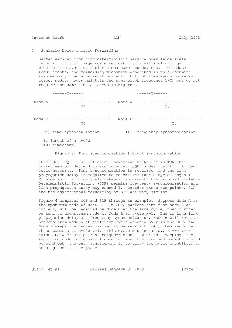
Internet-Draft LDN July 2018
3. Scalable Deterministic Forwarding
DetNet aims at providing deterministic service over large scale network. In such large scale network, it is difficulty to get precise time synchronization among numerous devices. To reduce requirements, the forwarding mechanism described in this document assumes only frequency synchronization but not time synchronization across nodes: nodes maintain the same clock frequency 1/T, but do not require the same time as shown in Figure 3.
<-----T-----> <-----T-----> | | | | | | Node A +-----------+-----------+ Node A +-----------+-----------+ T0 T0
| | | | | | Node B +-----------+-----------+ Node B +-----------+-----------+ T0 T0
(i) time synchronization (ii) frequency synchronization
T: length of a cycle T0: timestamp
Figure 3: Time Synchronization & Clock Synchronization
IEEE 802.1 CQF is an efficient forwarding mechanism in TSN that guarantees bounded end-to-end latency. CQF is designed for limited scale networks. Time synchronization is required, and the link propagation delay is required to be smaller than a cycle length T. Considering the large scale network deployment, the proposed Scalable Deterministic Forwarding (SDF) permits frequency synchronization and link propagation delay may exceed T. Besides these two points, CQF and the asynchronous forwarding of SDF are very similar.
Figure 4 compares CQF and SDF through an example. Suppose Node A is the upstream node of Node B. In CQF, packets sent from Node A at cycle x, will be received by Node B at the same cycle, then further be sent to downstream node by Node B at cycle x+1. Due to long link propagation delay and frequency synchronization, Node B will receive packets from Node A at different cycle denoted by y in the SDF, and Node B swaps the cycles carried in packets with y+1, then sends out those packets at cycle y+1. This cycle mapping (e.g., x --> y+1) exists between any pair of neighbor nodes. With this mapping, the receiving node can easily figure out when the received packets should be send out, the only requirement is to carry the cycle identifier of sending node in the packets.
Qiang, et al. Expires January 3, 2019 [Page 7]

Internet-Draft LDN July 2018
| cycle x | cycle x+1 | | cycle x | cycle x+1 |Node A +-----------+-----------+ Node A +-----------+-----------+ \ \ \packet \packet \receiving \receiving \ \ | V | cycle x+1 | | V | cycle y+1|Node B +-----------+-----------+ Node B +-----------+-----------+ cycle x \packet cycle y \packet \sending \sending \ \ \ \ V V
(i) CQF (ii) SDF
Figure 4: CQF & SDF
3.1. Three Queues
In CQF each port needs to maintain 2 (or 3) queues: one is used to buffer newly received packets, another one is used to store the packets that are going to be sent out, one more queue may be needed to avoid output starvation [scheduled-queues]. In SDF, at least 3 queues are needed.
As Figure 5 illustrated, a node may receive packets sent at two different cycles from a single upstream node due to the absence of time synchronization. Following the cycle mapping (i.e., x --> y+1), packets that carry cycle identifier x should be sent out by Node B at cycle y+1, and packets that carry cycle identifier x+1 should be sent out by Node B at cycle y+2. Therefore, two queues are needed to store the newly received packets, as well as one queue to store the sending packets. In order to absorb more link delay variation (such as on radio interface), more queues may be necessary.
| cycle x | cycle x+1 | Node A +-----------+-----------+ \ \ \ \packet \ \receiving | V V | | Node B +-----------+-----------+ cycle y cycle y+1
Figure 5: Three Queues in SDF
Qiang, et al. Expires January 3, 2019 [Page 8]

Internet-Draft LDN July 2018
3.2. Cycle Mapping
When this packet is received by Node B, some methods are possible how the forwarding plane could operate. In one method, Node B has a mapping determined by the control plane. Packets from (the link from) Node A indicating cycle x are mapping into cycle y+1. This mapping is necessary, because all the packets from one cycle of the sending node need to get into one cycle of the receiving node. This is called "configured cycle mapping".
Instead of configuring an explicit cycle mapping such as cycle x -> cycle y+1, the receiving Node B could also have the intelligence in the forwarding plane to recognize the first packet from (the link from) Node A that has a new cycle x number, and map this cycle x to the next cycle after the current cycle y, aka: cycle y+1. We call this option "self synchronized cycle mapping".
3.2.1. Cycle Identifier Carrying
In self synchronized cycle mapping, cycle identifier needs to be carried in the SDF packets, so that an appropriate queue can be selected accordingly. That means 2 bits are needed in the three queues model of SDF, in order to identify different cycles between a pair of neighboring nodes. There are several ways to carry this 2 bits cycle identifier. This document does not yet aim to propose one, but gives an (incomplete) list of ideas:
o DSCP of IPv4 Header
o Traffic Class of IPv6 Header
o TC of MPLS Header (used to be EXP)
o EtherType of Ethernet Header
o IPv6 Extension Header
o TLV of SRv6
o TC of MPLS-SR Header (used to be EXP)
o Three labels/adjacency SIDs for MPLS-SR
4. Scalable Resource Reservation
SDF must work with some resource reservation mechanisms, that can fulfill the role of the Scalable Resource Reservation (SRR). This resource reservation guarantees the necessary network resources when
Qiang, et al. Expires January 3, 2019 [Page 9]

Internet-Draft LDN July 2018
deterministic flows are scheduled including the slots through which the traffic travels hop-by-hop. Network nodes have to record how many network resources are reserved for a specific flow from when it starts to when it ends (e.g., <flow_identifier, reserved_resource, start_time, end_time>). Maintaining per-flow resource reservation state may be acceptable to edge nodes, but un-acceptable to core nodes. [draft-ietf-detnet-architecture] pointed out that aggregation must be supported for scalability.
SRR aggregates per-flow resource reservation states for each time slot:
1. Dividing time into time slots. Then the per-flow resource reservation states can be expressed as <flow_identifier, reserved_resource, start_time_slot, end_time_slot> accordingly. Note that time slot here is irrelevant to the cycle in SDF.
2. Edge node still maintains per-flow resource reservation states. While core node calculates and maintains the sum of reserved_resources (or remaining resources) of each time slot. That is a core node just needs to maintain a variable for each time slot. Suppose that a core node can maintain K time slots’ results, i.e., the aggregated resource reservation window of a core node is K.
3. New resource reservation request succeed only if there are sufficient resources along the path. Resource is reserved in unit of time slot, and at most K time slots. If more than K time slots’ resources are needed, edge node/host can send renewal request before the expiration of K time slots. Edge node/host also can active teardown the resource reservation along the path.
4. Core nodes refresh their aggregated resource reservation windows according to the per-flow resource reservation states maintained by edge nodes.
5. Performance Analysis
5.1. Queueing Delay
We consider forwarding from an LDN node A via an LDN node B to an LDN node C and call the single-hop LDN delay the time between a packet being sent by A and the time it is re-sent by B. This single-hop delay is composed from the A->B propagation delay and the single-hop queuing delay A->B.
Qiang, et al. Expires January 3, 2019 [Page 10]
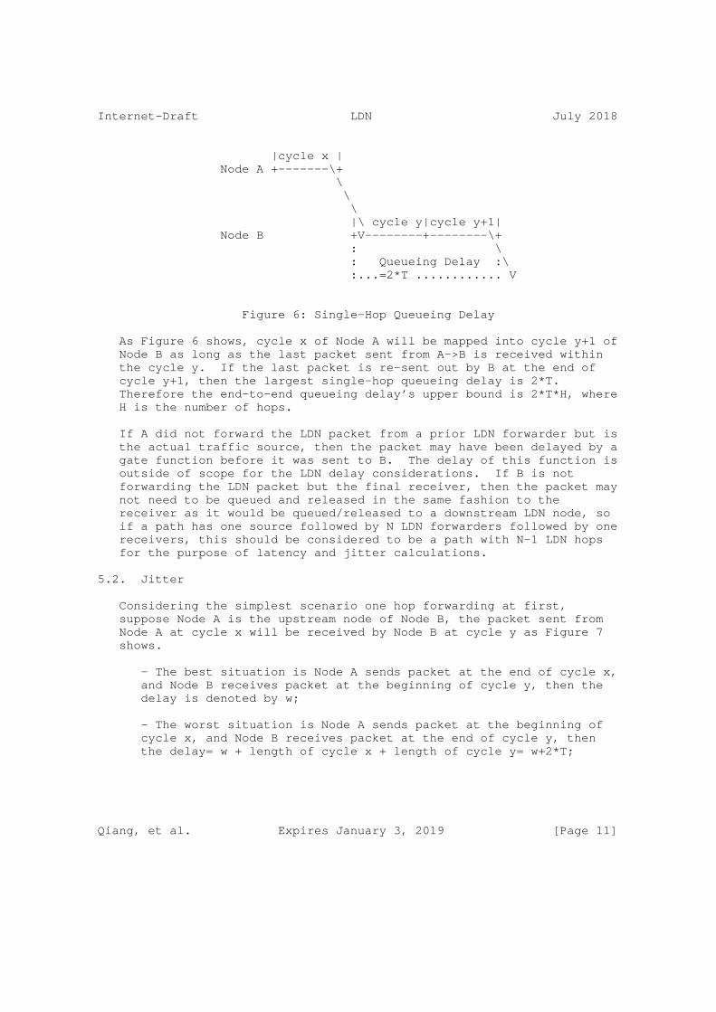
Internet-Draft LDN July 2018
|cycle x | Node A +-------\+ \ \ \ |\ cycle y|cycle y+1| Node B +V--------+--------\+ : \ : Queueing Delay :\ :...=2*T ............ V
Figure 6: Single-Hop Queueing Delay
As Figure 6 shows, cycle x of Node A will be mapped into cycle y+1 of Node B as long as the last packet sent from A->B is received within the cycle y. If the last packet is re-sent out by B at the end of cycle y+1, then the largest single-hop queueing delay is 2*T. Therefore the end-to-end queueing delay’s upper bound is 2*T*H, where H is the number of hops.
If A did not forward the LDN packet from a prior LDN forwarder but is the actual traffic source, then the packet may have been delayed by a gate function before it was sent to B. The delay of this function is outside of scope for the LDN delay considerations. If B is not forwarding the LDN packet but the final receiver, then the packet may not need to be queued and released in the same fashion to the receiver as it would be queued/released to a downstream LDN node, so if a path has one source followed by N LDN forwarders followed by one receivers, this should be considered to be a path with N-1 LDN hops for the purpose of latency and jitter calculations.
5.2. Jitter
Considering the simplest scenario one hop forwarding at first, suppose Node A is the upstream node of Node B, the packet sent from Node A at cycle x will be received by Node B at cycle y as Figure 7 shows.
- The best situation is Node A sends packet at the end of cycle x, and Node B receives packet at the beginning of cycle y, then the delay is denoted by w;
- The worst situation is Node A sends packet at the beginning of cycle x, and Node B receives packet at the end of cycle y, then the delay= w + length of cycle x + length of cycle y= w+2*T;
Qiang, et al. Expires January 3, 2019 [Page 11]

Internet-Draft LDN July 2018
- Hence the jitter’s upper bound of this simplest scenario= worst case-best case=2*T.
|cycle x | |cycle x | Node A +-------\+ Node A +\-------+ :\ \ : : \ -------------\ : \ : \ :w |\ | :w| \ | Node B : +V--------+ Node B : +--------V+ cycle y cycle y
(a) best situation (b) worst situation
Figure 7: Jitter Analysis for One Hop Forwarding
Next considering two hops forwarding as Figure 8 shows.
- The best situation is Node A sends packet at the end of cycle x, and Node C receives packet at the beginning of cycle z, then the delay is denoted by w’;
- The worst situation is Node A sends packet at the beginning of cycle x, and Node C receives packet at the end of cycle z, then the delay= w’ + length of cycle x + length of cycle z= w’+2*T;
- Hence the jitter’s upper bound = worst case-best case=2*T.
Qiang, et al. Expires January 3, 2019 [Page 12]

Internet-Draft LDN July 2018
|cycle x | Node A +-------\+ \ :\| cycle y | Node B : \---------+ : \ : \--------\ : \ | Node C ......w’......+V--------+ cycle z
(a) best situation
|cycle x | Node A +\-------+ \ : \ : | cycle y | Node B \ : +---------+ \ : ---:--------------------\ : | \ | Node C :......w’.....+--------V+ cycle z
(b) worst situation
Figure 8: Jitter Analysis for Two Hops Forwarding
And so on. For multi-hop forwarding, the end-to-end delay will increase as the number of hops increases, while the delay variation (jitter) still does not exceed 2*T.
6. IANA Considerations
This document makes no request of IANA.
7. Security Considerations
Security issues have been carefully considered in [draft-ietf-detnet-security]. More discussion is TBD.
8. Acknowledgements
TBD.
Qiang, et al. Expires January 3, 2019 [Page 13]

Internet-Draft LDN July 2018
9. Normative References
[draft-ietf-detnet-architecture] "DetNet Architecture", <https://datatracker.ietf.org/doc/ draft-ietf-detnet-architecture/>.
[draft-ietf-detnet-dp-sol] "DetNet Data Plane Encapsulation", <https://datatracker.ietf.org/doc/ draft-ietf-detnet-dp-sol/>.
[draft-ietf-detnet-problem-statement] "DetNet Problem Statement", <https://datatracker.ietf.org/doc/ draft-ietf-detnet-problem-statement/>.
[draft-ietf-detnet-security] "DetNet Security Considerations", <https://datatracker.ietf.org/doc/ draft-ietf-detnet-security/>.
[draft-ietf-detnet-use-cases] "DetNet Use Cases", <https://datatracker.ietf.org/doc/ draft-ietf-detnet-use-cases/>.
[RFC2119] Bradner, S., "Key words for use in RFCs to Indicate Requirement Levels", BCP 14, RFC 2119, DOI 10.17487/RFC2119, March 1997, <https://www.rfc-editor.org/info/rfc2119>.
[scheduled-queues] "Scheduled queues, UBS, CQF, and Input Gates", <http://www.ieee802.org/1/files/public/docs2015/ new-nfinn-input-gates-0115-v04.pdf>.
Authors’ Addresses
Li Qiang (editor) Huawei Beijing China
Email: [email protected]
Qiang, et al. Expires January 3, 2019 [Page 14]

Internet-Draft LDN July 2018
Bingyang Liu Huawei Beijing China
Email: [email protected]
Toerless Eckert (editor) Huawei USA - Futurewei Technologies Inc. 2330 Central Expy Santa Clara 95050 USA
Email: [email protected]
Liang Geng China Mobile Beijing China
Email: [email protected]
Lei Wang China Mobile Beijing China
Email: [email protected]
Qiang, et al. Expires January 3, 2019 [Page 15]