oprsd¥ep A„L$ 40 sp. 16 dpQ®$ - 22 dpQ®$ 2019 · 1 · oprsd¥ep A„L$ 40 sp. 16 dpQ®$ - 22 dpQ®$ 2019 ·
TN 018: 2014
3183272_3 Asset Standards Authority © State of NSW through Transport for NSW Page 1 of 1
Technical Note TN 018: 2014
Subject: Removal of EP 20 10 00 02 SP High Voltage Cable
Issued date 12 March 2014 Effective dates 12 March 2014
For queries regarding this document [email protected]
www.asa.transport.nsw.gov.au
This technical note is issued by the Asset Standards Authority as a notification to removel from
use the following RailCorp document:
Reference Number Title Version Issue Date
EP 20 10 00 02 SP High Voltage Cable 3.1 August 2011
EP 20 10 00 02 SP High Voltage Cable is a legacy RailCorp document and should be used for
reference purposes only. T HR EL 20001 ST High Voltage AC and 1500 V DC Traction Power
Supply Cable Requirements supersedes this document.
Authorisation
Technical content prepared by
Checked and approved by
Interdisciplinary coordination checked by
Authorised for release
Signature
Name Wilfred Leung Neal Hook David Spiteri Graham Bradshaw
Position Principal Engineer, Overhead Lines and Cables
Lead Electrical Engineer
Chief Engineer, Rail Principal Manager Network Standards & Services
Sup
erse
ded
by T
HR
EL
2000
1 S
T
HIGH VOLTAGE CABLE
EP 20 10 00 02 SP
Engineering Standard Electrical
Version 3.1
Issued August 2011
Owner: Chief Engineer Electrical
Approved by:
Neal Hook Chief Engineer Electrical
Authorised by:
Neal Hook Chief Engineer Electrical
En
gin
eeri
ng
Sta
nd
ard
Disclaimer
This document was prepared for use on the RailCorp Network only.
RailCorp makes no warranties, express or implied, that compliance with the contents of this document shall be sufficient to ensure safe systems or work or operation. It is the document user’s sole responsibility to ensure that the copy of the document it is viewing is the current version of the document as in use by RailCorp.
RailCorp accepts no liability whatsoever in relation to the use of this document by any party, and RailCorp excludes any liability which arises in any manner by the use of this document.
Copyright
The information in this document is protected by Copyright and no part of this document may be reproduced, altered, stored or transmitted by any person without the prior consent of RailCorp.
Sup
erse
ded
by T
HR
EL
2000
1 S
T RailCorp Engineering Standard — Electrical High voltage cable EP 20 10 00 02 SP
Document control
© RailCorp Page 2 of 21 Issued August 2011 UNCONTROLLED WHEN PRINTED Version 3.1
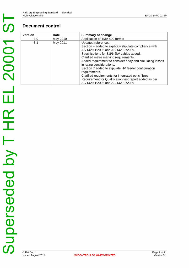
Version Date Summary of change 3.0 May 2010 Application of TMA 400 format 3.1 May 2011 Updated references.
Section 4 added to explicitly stipulate compliance with AS 1429.1:2006 and AS 1429.2:2009. Specifications for 3.8/6.6kV cables added. Clarified metre marking requirements. Added requirement to consider eddy and circulating losses in rating considerations. Section 7 added to stipulate HV feeder configuration requirements. Clarified requirements for integrated optic fibres. Requirement for Qualification test report added as per AS 1429.1:2006 and AS 1429.2:2009
Sup
erse
ded
by T
HR
EL
2000
1 S
T RailCorp Engineering Standard — Electrical High voltage cable EP 20 10 00 02 SP
Contents
© RailCorp Page 3 of 21 Issued August 2011 UNCONTROLLED WHEN PRINTED Version 3.1
1 Introduction .............................................................................................................................4 2 Scope and application............................................................................................................4 3 References...............................................................................................................................4 3.1 Australian and international standards......................................................................................4 3.2 RailCorp documents..................................................................................................................5 4 General .....................................................................................................................................5 5 Preferred cable sizes and applications.................................................................................5 6 Ratings .....................................................................................................................................9 6.1 Conditions used in determining current ratings ........................................................................9
6.1.1 Conditions used to determine the continuous current ratings shown in Tables 5, 6 and 7 .......................................................................................................9
6.1.2 Derating ...................................................................................................................10 6.2 Short time ratings ....................................................................................................................11 6.3 Fault ratings ............................................................................................................................11 6.4 Specific cables ........................................................................................................................11 7 Configuration of high voltage feeders ................................................................................14 8 Manufacturing process.........................................................................................................14 9 Cables for use in tunnels or underground stations ..........................................................15 10 Integrated optic fibres for temperature monitoring...........................................................15 11 Inspection & Testing.............................................................................................................16 11.1 Type tests................................................................................................................................16 11.2 Routine tests ...........................................................................................................................16 11.3 Sample tests ...........................................................................................................................16 11.4 Test certificates and Qualification test report..........................................................................16 12 Data set associated with the cable(s) .................................................................................16 12.1 Drawings and Information .......................................................................................................16 12.2 Test results..............................................................................................................................16 12.3 Technical Schedule.................................................................................................................17 Appendix A Technical Schedule (Information to be provided by Tenderers) ......................18 Details of optic fibres ...........................................................................................................................19 Appendix B Cable drums and preparation for delivery ..........................................................20 Appendix C Request for Tender - Check List ..........................................................................21 Information to be supplied to tenderers..................................................................................................21 Information to be supplied by tenderers .................................................................................................21 Information to be supplied by the successful tenderer...........................................................................21
Sup
erse
ded
by T
HR
EL
2000
1 S
T RailCorp Engineering Standard — Electrical High voltage cable EP 20 10 00 02 SP
© RailCorp Page 4 of 21 Issued August 2011 UNCONTROLLED WHEN PRINTED Version 3.1
1 Introduction This document sets out:
• the requirements for high voltage cables to suit particular applications • continuous ratings of common high voltage ac cables used by RailCorp • the preferred cable sizes to be used in order to reduce and rationalise the number of
different size cables in service.
This document does not cover the requirements for 1500V dc cables and traction rectifier transformer secondary circuit cables. The requirements for these cables are covered in EP 20 10 00 01 SP – “1500V dc cables and cable ratings”. However, specifications for 3.8/6.6kV cables used in the 1500V dc traction system are given in this document.
Joints and terminations used with RailCorp high voltage cables shall be approved by the RailCorp Chief Engineer Electrical prior to installation. Refer to EP 20 00 03 01 SP.
Alterations and repair to high voltage cables should be in accordance with this document only so far as the extent of change.
For more information about conducting safety risk management assessments when assessing requirements for high voltage cables to suit particular applications, see RailCorp Safety Management System Element 6: Risk Management.
2 Scope and application Cable manufacturers usually provide maximum continuous current rating data for cables direct buried, in buried ducts and in air (in shade) conditions. Derating factors are usually also provided to cater for situations where a number of circuits are installed in close proximity to one another and/or, where cables are installed at greater than normal depth and/or where cables are installed in soils exhibiting poor thermal resistivity.
In addition RailCorp cables are often exposed to direct sun and installed in elevated steel troughing which directly affects the current rating of the cable.
This document provides current rating data for the aforementioned conditions.
The preferred cable construction configurations described in this document may not be suitable for all applications. Examples of site conditions or project requirements for which the preferred cable construction are not suitable include, but are not limited to:
• The cable is immersed in water for extensive time periods. • Anti-termite protection
The designer shall consider installation and site conditions in specifying the cable for each project. Use of non-preferred cable types shall be subject to approval by the RailCorp Chief Engineer Electrical on a case by case basis.
3 References
3.1 Australian and international standards
The following documents contain provisions that, through reference in this text, provide further information and constitute provisions of this document. At the time of publication, the editions indicated below were valid.
Sup
erse
ded
by T
HR
EL
2000
1 S
T RailCorp Engineering Standard — Electrical High voltage cable EP 20 10 00 02 SP
© RailCorp Page 5 of 21 Issued August 2011 UNCONTROLLED WHEN PRINTED Version 3.1
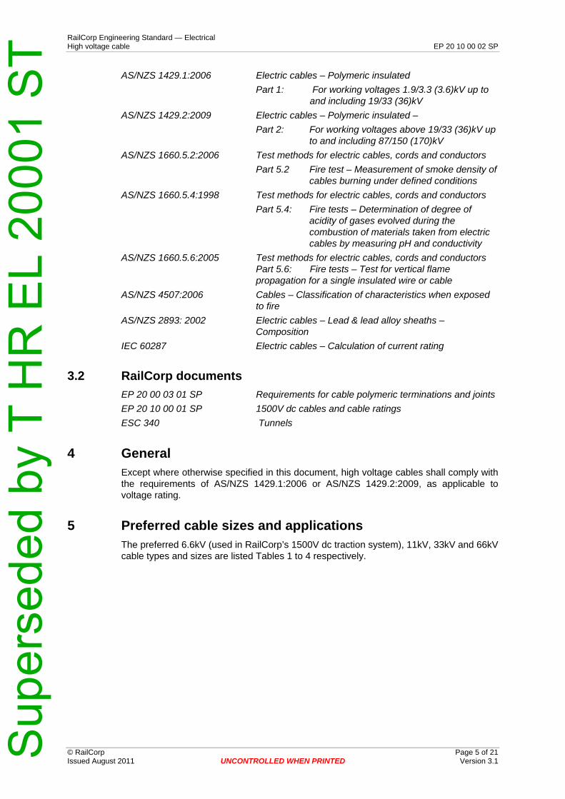
AS/NZS 1429.1:2006 Electric cables – Polymeric insulated
Part 1: For working voltages 1.9/3.3 (3.6)kV up to and including 19/33 (36)kV
AS/NZS 1429.2:2009 Electric cables – Polymeric insulated –
Part 2: For working voltages above 19/33 (36)kV up to and including 87/150 (170)kV
AS/NZS 1660.5.2:2006 Test methods for electric cables, cords and conductors
Part 5.2 Fire test – Measurement of smoke density of cables burning under defined conditions
AS/NZS 1660.5.4:1998 Test methods for electric cables, cords and conductors
Part 5.4: Fire tests – Determination of degree of acidity of gases evolved during the combustion of materials taken from electric cables by measuring pH and conductivity
AS/NZS 1660.5.6:2005 Test methods for electric cables, cords and conductors Part 5.6: Fire tests – Test for vertical flame propagation for a single insulated wire or cable
AS/NZS 4507:2006 Cables – Classification of characteristics when exposed to fire
AS/NZS 2893: 2002 Electric cables – Lead & lead alloy sheaths – Composition
IEC 60287 Electric cables – Calculation of current rating
3.2 RailCorp documents
EP 20 00 03 01 SP Requirements for cable polymeric terminations and joints
EP 20 10 00 01 SP 1500V dc cables and cable ratings
ESC 340 Tunnels
4 General Except where otherwise specified in this document, high voltage cables shall comply with the requirements of AS/NZS 1429.1:2006 or AS/NZS 1429.2:2009, as applicable to voltage rating.
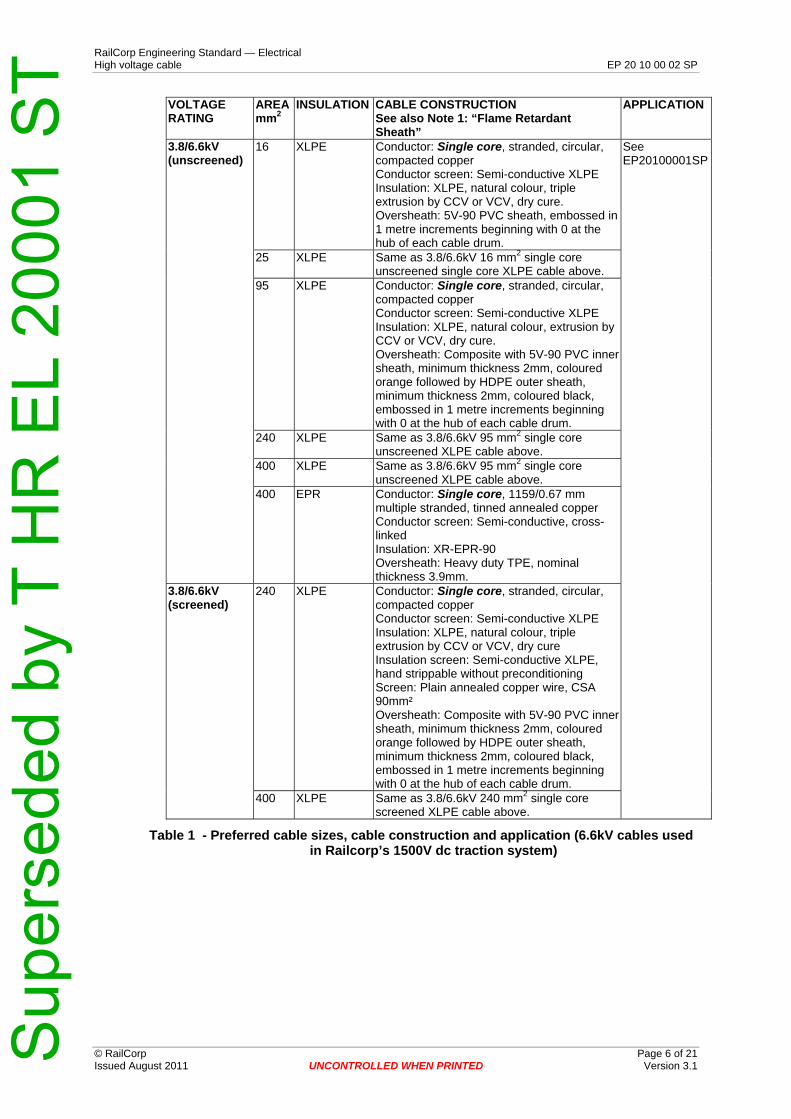
5 Preferred cable sizes and applications The preferred 6.6kV (used in RailCorp’s 1500V dc traction system), 11kV, 33kV and 66kV cable types and sizes are listed Tables 1 to 4 respectively.
Sup
erse
ded
by T
HR
EL
2000
1 S
T RailCorp Engineering Standard — Electrical High voltage cable EP 20 10 00 02 SP
© RailCorp Page 6 of 21 Issued August 2011 UNCONTROLLED WHEN PRINTED Version 3.1
VOLTAGE RATING
AREA 2mm
INSULATION CABLE CONSTRUCTION See also Note 1: “Flame Retardant Sheath”
APPLICATION
3.8/6.6kV (unscreened)
16 XLPE Conductor: Single core, stranded, circular, compacted copper Conductor screen: Semi-conductive XLPE Insulation: XLPE, natural colour, triple extrusion by CCV or VCV, dry cure. Oversheath: 5V-90 PVC sheath, embossed in 1 metre increments beginning with 0 at the hub of each cable drum.
See EP20100001SP
25 XLPE Same as 3.8/6.6kV 16 mm2 single core unscreened single core XLPE cable above.
95 XLPE Conductor: Single core, stranded, circular, compacted copper Conductor screen: Semi-conductive XLPE Insulation: XLPE, natural colour, extrusion by CCV or VCV, dry cure. Oversheath: Composite with 5V-90 PVC inner sheath, minimum thickness 2mm, coloured orange followed by HDPE outer sheath, minimum thickness 2mm, coloured black, embossed in 1 metre increments beginning with 0 at the hub of each cable drum.
240 XLPE Same as 3.8/6.6kV 95 mm2 single core unscreened XLPE cable above.
400 XLPE Same as 3.8/6.6kV 95 mm2 single core unscreened XLPE cable above.
400 EPR Conductor: Single core, 1159/0.67 mm multiple stranded, tinned annealed copper Conductor screen: Semi-conductive, cross-linked Insulation: XR-EPR-90 Oversheath: Heavy duty TPE, nominal thickness 3.9mm.
3.8/6.6kV (screened)
240 XLPE Conductor: Single core, stranded, circular, compacted copper Conductor screen: Semi-conductive XLPE Insulation: XLPE, natural colour, triple extrusion by CCV or VCV, dry cure Insulation screen: Semi-conductive XLPE, hand strippable without preconditioning Screen: Plain annealed copper wire, CSA 90mm² Oversheath: Composite with 5V-90 PVC inner sheath, minimum thickness 2mm, coloured orange followed by HDPE outer sheath, minimum thickness 2mm, coloured black, embossed in 1 metre increments beginning with 0 at the hub of each cable drum.
400 XLPE Same as 3.8/6.6kV 240 mm2 single core screened XLPE cable above.
Table 1 - Preferred cable sizes, cable construction and application (6.6kV cables used in Railcorp’s 1500V dc traction system)
Sup
erse
ded
by T
HR
EL
2000
1 S
T RailCorp Engineering Standard — Electrical High voltage cable EP 20 10 00 02 SP
© RailCorp Page 7 of 21 Issued August 2011 UNCONTROLLED WHEN PRINTED Version 3.1
VOLTAGE RATING
AREA 2mm
INSULATION CABLE CONSTRUCTION See also Note 1: “Flame Retardant Sheath”
APPLICATION
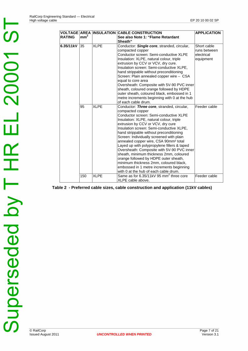
6.35/11kV
35 XLPE Conductor: Single core, stranded, circular, compacted copper Conductor screen: Semi-conductive XLPE Insulation: XLPE, natural colour, triple extrusion by CCV or VCV, dry cure. Insulation screen: Semi-conductive XLPE, hand strippable without preconditioning Screen: Plain annealed copper wire – CSA equal to core area Oversheath: Composite with 5V-90 PVC inner sheath, coloured orange followed by HDPE outer sheath, coloured black, embossed in 1 metre increments beginning with 0 at the hub of each cable drum.
Short cable runs between electrical equipment
95 XLPE Conductor: Three core, stranded, circular, compacted copper Conductor screen: Semi-conductive XLPE Insulation: XLPE, natural colour, triple extrusion by CCV or VCV, dry cure Insulation screen: Semi-conductive XLPE, hand strippable without preconditioning Screen: Individually screened with plain annealed copper wire, CSA 90mm² total Layed up with polypropylene fillers & taped Oversheath: Composite with 5V-90 PVC inner sheath, minimum thickness 2mm, coloured orange followed by HDPE outer sheath, minimum thickness 2mm, coloured black, embossed in 1 metre increments beginning with 0 at the hub of each cable drum.
Feeder cable
150 XLPE Same as for 6.35/11kV 95 mm2 three core XLPE cable above.
Feeder cable
Table 2 - Preferred cable sizes, cable construction and application (11kV cables)
Sup
erse
ded
by T
HR
EL
2000
1 S
T RailCorp Engineering Standard — Electrical High voltage cable EP 20 10 00 02 SP
© RailCorp Page 8 of 21 Issued August 2011 UNCONTROLLED WHEN PRINTED Version 3.1
VOLTAGE AREA INSULATION CABLE CONSTRUCTION APPLICATIONRATING 2mm See also Note 1: “Flame Retardant
Sheath” & Note 2 “Integrated Optic Fibres”
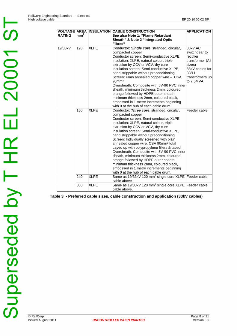
19/33kV 120 XLPE Conductor: Single core, stranded, circular, compacted copper Conductor screen: Semi-conductive XLPE Insulation: XLPE, natural colour, triple extrusion by CCV or VCV, dry cure Insulation screen: Semi-conductive XLPE, hand strippable without preconditioning Screen: Plain annealed copper wire – CSA 90mm² Oversheath: Composite with 5V-90 PVC inner sheath, minimum thickness 2mm, coloured orange followed by HDPE outer sheath, minimum thickness 2mm, coloured black, embossed in 1 metre increments beginning with 0 at the hub of each cable drum.
33kV AC switchgear to rectifier transformer (All sizes) 33kV cables for 33/11 transformers up to 7.5MVA
150 XLPE Conductor: Three core, stranded, circular, compacted copper Conductor screen: Semi-conductive XLPE Insulation: XLPE, natural colour, triple extrusion by CCV or VCV, dry cure Insulation screen: Semi-conductive XLPE, hand strippable without preconditioning Screen: Individually screened with plain annealed copper wire, CSA 90mm² total Layed up with polypropylene fillers & taped Oversheath: Composite with 5V-90 PVC inner sheath, minimum thickness 2mm, coloured orange followed by HDPE outer sheath, minimum thickness 2mm, coloured black, embossed in 1 metre increments beginning with 0 at the hub of each cable drum.
Feeder cable
240 XLPE Same as 19/33kV 120 mm2 single core XLPE cable above.
Feeder cable
300 XLPE Same as 19/33kV 120 mm2 single core XLPE cable above.
Feeder cable
Table 3 - Preferred cable sizes, cable construction and application (33kV cables)
Sup
erse
ded
by T
HR
EL
2000
1 S
T RailCorp Engineering Standard — Electrical High voltage cable EP 20 10 00 02 SP
© RailCorp Page 9 of 21 Issued August 2011 UNCONTROLLED WHEN PRINTED Version 3.1
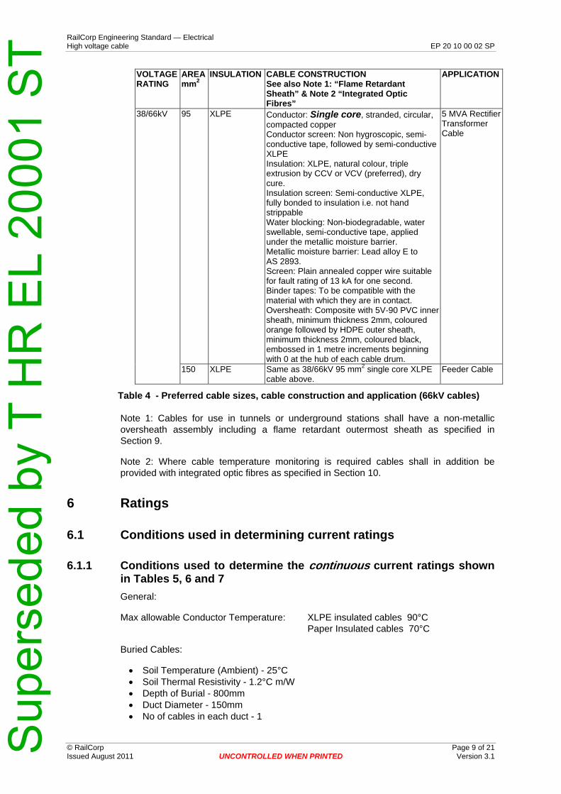
VOLTAGE AREA INSULATION CABLE CONSTRUCTION APPLICATIONRATING 2mm See also Note 1: “Flame Retardant
Sheath” & Note 2 “Integrated Optic Fibres”
38/66kV 95 XLPE Conductor: Single core, stranded, circular, compacted copper Conductor screen: Non hygroscopic, semi-conductive tape, followed by semi-conductive XLPE Insulation: XLPE, natural colour, triple extrusion by CCV or VCV (preferred), dry cure. Insulation screen: Semi-conductive XLPE, fully bonded to insulation i.e. not hand strippable Water blocking: Non-biodegradable, water swellable, semi-conductive tape, applied under the metallic moisture barrier. Metallic moisture barrier: Lead alloy E to AS 2893. Screen: Plain annealed copper wire suitable for fault rating of 13 kA for one second. Binder tapes: To be compatible with the material with which they are in contact. Oversheath: Composite with 5V-90 PVC inner sheath, minimum thickness 2mm, coloured orange followed by HDPE outer sheath, minimum thickness 2mm, coloured black, embossed in 1 metre increments beginning with 0 at the hub of each cable drum.
5 MVA Rectifier Transformer Cable
150 XLPE Same as 38/66kV 95 mm2 single core XLPE cable above.
Feeder Cable
Table 4 - Preferred cable sizes, cable construction and application (66kV cables)
Note 1: Cables for use in tunnels or underground stations shall have a non-metallic oversheath assembly including a flame retardant outermost sheath as specified in Section 9.
Note 2: Where cable temperature monitoring is required cables shall in addition be provided with integrated optic fibres as specified in Section 10.
6 Ratings
6.1 Conditions used in determining current ratings
6.1.1 Conditions used to determine the continuous current ratings shown in Tables 5, 6 and 7
General:
Max allowable Conductor Temperature: XLPE insulated cables 90°C Paper Insulated cables 70°C
Buried Cables:
• Soil Temperature (Ambient) - 25°C • Soil Thermal Resistivity - 1.2°C m/W • Depth of Burial - 800mm • Duct Diameter - 150mm • No of cables in each duct - 1

Sup
erse
ded
by T
HR
EL
2000
1 S
T RailCorp Engineering Standard — Electrical High voltage cable EP 20 10 00 02 SP
© RailCorp Page 10 of 21 Issued August 2011 UNCONTROLLED WHEN PRINTED Version 3.1
Cables in Air:
• Air Temperature (Ambient) - 40°C • Solar Radiation - 1000W/m2 • Cable Emissivity - 0.7 • Steel Trough Emissivity - 0.3 • Trough Size - 150mm x 150mm; one circuit per trough
6.1.2 Derating
The current ratings of cables are affected by a number of factors as discussed below. For simple installation configurations, it is acceptable to apply derating factors shown in Tables 8 to 11. For more complex installation configurations, the as installed current rating shall be determined in accordance with IEC 60287 using appropriate softwares that have been accepted by the RailCorp Chief Engineer Electrical.
Cables in close proximity: Current ratings shown in Section 6.4 are subject to derating where a number of cable circuits are installed in close proximity to one another. With cables in ground, a derating factor must be applied when the spacing between circuits is less than 1.0m. Cables in unenclosed installations must be derated when the spacing is less than 3 times the cable diameter. Typical derating factors are given in Table 10 and Table 11.
Cables installed at greater than normal depth: Current ratings shown in Section 6.4 are also subject to derating where cables are installed in ground (direct buried or ducted) at depths exceeding that shown above. This may have particular relevance to cables within ducts installed by directional boring. Typical derating factors for cables up to 33kV are given in Table 8 and Table 9. For guidance regarding derating factors applicable to 66kV cables the cable manufacturer should be consulted.
Cables installed in soils of poor thermal resistivity: Some soils such as marshy ground, coarse sand and, reclaimed and rubbish ground generally exhibit poor thermal resistivity i.e. higher than the value shown above. In these situations it is now accepted practice to measure soil thermal resistivity prior to selecting cable size and either applying a derating factor or, preferably, employing installation techniques that will remedy the situation, eg bedding cables and backfilling trenches with material of low thermal resistivity such as 14:1 sand / cement mix.
Note particularly - as heat is generated by current (I²R), not voltage, this situation is applicable to all cables, not just higher voltage cables.
Eddy and circulating currents: The ratings given in Tables 5 to 7 are based on installations with cable screens solidly bonded to earth at both ends, and with eddy and circulating current losses ignored. The designer shall assess the effect of such lossess for actual conditions. In particular, careful consideration should be given to situations such as those listed below:
• Cables with a rated voltage of 66kV or above • Long runs of cables (> 3.5km) • Single core cables are not installed in a close configuration for significant portions
of the route
Alternative bonding configuration should be considered if the assessment has determined that the losses will result in unacceptable levels of derating.

Sup
erse
ded
by T
HR
EL
2000
1 S
T RailCorp Engineering Standard — Electrical High voltage cable EP 20 10 00 02 SP
6.2 Short time ratings
© RailCorp Page 11 of 21 Issued August 2011 UNCONTROLLED WHEN PRINTED Version 3.1
It is permissible that a cable be designed for short term loading in excess of the continuous rating provided that appropriate derating factors are applied.
6.3 Fault ratings The phase conductors and screen should be rated to carry the maximum earth fault current at the location for the longest clearing time of the back-up protection covering that fault.
The phase conductors shall be rated to carry the maximum 3-phase fault current for the longest clearing time of the back-up protection covering that fault.
6.4 Specific cables Cables used on the RailCorp system shall have continuous current rating of at least that listed in Tables 5, 6 and 7 when operated under the conditions set out in Section 6.1. The existing RailCorp network contains various cable types and sizes that are not to be used for new installations. Information for these non-preferred cables are shown shaded in the tables, and is provided for reference purposes only.
3.8/6.6kV cables listed in Table 1 are used in RailCorp’s 1500V dc traction system. Refer to EP 20 10 00 01 SP for the ratings of these cables.
Cores Maximum Continuous Current Rating In Amps
Insulation Type
Area mm2 No.
Direct Buried
In Buried Ducts
In Air in Shade
In Air in Sun
In Elevated Steel
Troughing in Sun
XLPE 35 1 175 150 180 160 120
XLPE 35 3 165 145 160 150 120
XLPE 50 1 205 175 215 180 150
XLPE 50 3 195 170 190 175 145
XLPE 95 1 290 250 320 250 200
XLPE 95 3 270 240 275 230 200
XLPE 150 1 370 320 420 330 260
XLPE 150 3 345 305 360 310 260
XLPE 240 1 475 410 560 420 340
XLPE 240 3 440 385 480 390 340
Paper / Lead 25 3 90 80 75 75 65
Paper / Lead 50 1 170 155 160 155 120
Paper / Lead 50 3 160 140 140 140 120
Paper / Lead 95 1 250 255 245 250 180
Paper / Lead 95 3 240 205 210 210 180
Paper / Lead 150 1 325 285 325 290 230
Paper / Lead 150 3 305 255 280 265 230
Table 5 - 11kV cables – Continuous current in Amps
Sup
erse
ded
by T
HR
EL
2000
1 S
T RailCorp Engineering Standard — Electrical High voltage cable EP 20 10 00 02 SP
© RailCorp Page 12 of 21 Issued August 2011 UNCONTROLLED WHEN PRINTED Version 3.1
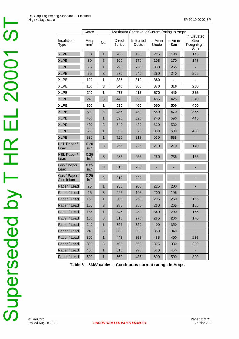
Cores Maximum Continuous Current Rating In Amps
Insulation Type
Area 2mm
No. Direct Buried
In Buried Ducts
In Air in Shade
In Air in Sun
In Elevated Steel
Troughing in Sun
XLPE 50 1 205 180 225 180 145
XLPE 50 3 190 170 195 170 145
XLPE 95 1 290 255 330 255 -
XLPE 95 3 270 240 280 240 205
XLPE 120 1 335 310 380 - -
XLPE 150 3 340 305 370 310 260
XLPE 240 1 475 415 570 440 355
XLPE 240 3 440 390 485 425 340
XLPE 300 1 530 460 650 500 400
XLPE 300 3 485 430 550 470 375
XLPE 400 1 590 520 740 590 445
XLPE 400 3 540 480 620 530 -
XLPE 500 1 650 570 830 600 490
XLPE 630 1 720 615 930 665 -
HSL Paper / Lead
0.20 in.2
3 255 225 210 210 140
HSL Paper / Lead
0.25 in.2
3 285 255 250 235 155
Gas / Paper / Lead
0.25 in.2
3 310 280 - - -
Gas / Paper / Aluminium
0.25 in.2
3 310 280 - - -
Paper / Lead 95 1 235 200 225 200 -
Paper / Lead 95 3 225 195 200 195 -
Paper / Lead 150 1 305 250 295 260 155
Paper / Lead 150 3 285 255 260 265 155
Paper / Lead 185 1 345 280 340 290 175
Paper / Lead 185 3 315 270 295 280 170
Paper / Lead 240 1 395 320 400 350 -
Paper / Lead 240 3 365 325 350 340 -
Paper / Lead 300 1 445 355 455 400 235
Paper / Lead 300 3 405 360 395 380 220
Paper / Lead 400 1 510 395 530 450 -
Paper / Lead 500 1 560 435 600 500 300
Table 6 - 33kV cables – Continuous current ratings in Amps
Sup
erse
ded
by T
HR
EL
2000
1 S
T
UNCONTROLLED WHEN PRINTED Page 13 of 21
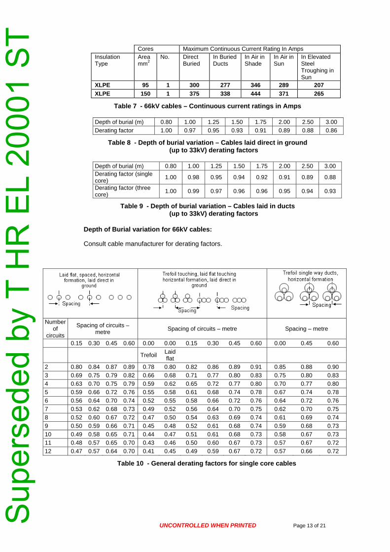
Cores Maximum Continuous Current Rating In Amps Insulation Area No. Direct In Buried In Air in In Air in In Elevated Type 2mm Buried Ducts Shade Sun Steel
Troughing in Sun
XLPE 95 1 300 277 346 289 207 XLPE 150 1 375 338 444 371 265
Table 7 - 66kV cables – Continuous current ratings in Amps
Depth of burial (m) 0.80 1.00 1.25 1.50 1.75 2.00 2.50 3.00
Derating factor 1.00 0.97 0.95 0.93 0.91 0.89 0.88 0.86
Table 8 - Depth of burial variation – Cables laid direct in ground (up to 33kV) derating factors
Depth of burial (m) 0.80 1.00 1.25 1.50 1.75 2.00 2.50 3.00 Derating factor (single core)
1.00 0.98 0.95 0.94 0.92 0.91 0.89 0.88
Derating factor (three core)
1.00 0.99 0.97 0.96 0.96 0.95 0.94 0.93
Table 9 - Depth of burial variation – Cables laid in ducts (up to 33kV) derating factors
Depth of Burial variation for 66kV cables:
Consult cable manufacturer for derating factors.
Number
of circuits
Spacing of circuits – metre
Spacing of circuits – metre Spacing – metre
0.15 0.30 0.45 0.60 0.00 0.00 0.15 0.30 0.45 0.60 0.00 0.45 0.60
Trefoil
Laid flat
2 0.80 0.84 0.87 0.89 0.78 0.80 0.82 0.86 0.89 0.91 0.85 0.88 0.90
3 0.69 0.75 0.79 0.82 0.66 0.68 0.71 0.77 0.80 0.83 0.75 0.80 0.83
4 0.63 0.70 0.75 0.79 0.59 0.62 0.65 0.72 0.77 0.80 0.70 0.77 0.80
5 0.59 0.66 0.72 0.76 0.55 0.58 0.61 0.68 0.74 0.78 0.67 0.74 0.78
6 0.56 0.64 0.70 0.74 0.52 0.55 0.58 0.66 0.72 0.76 0.64 0.72 0.76
7 0.53 0.62 0.68 0.73 0.49 0.52 0.56 0.64 0.70 0.75 0.62 0.70 0.75
8 0.52 0.60 0.67 0.72 0.47 0.50 0.54 0.63 0.69 0.74 0.61 0.69 0.74
9 0.50 0.59 0.66 0.71 0.45 0.48 0.52 0.61 0.68 0.74 0.59 0.68 0.73
10 0.49 0.58 0.65 0.71 0.44 0.47 0.51 0.61 0.68 0.73 0.58 0.67 0.73
11 0.48 0.57 0.65 0.70 0.43 0.46 0.50 0.60 0.67 0.73 0.57 0.67 0.72
12 0.47 0.57 0.64 0.70 0.41 0.45 0.49 0.59 0.67 0.72 0.57 0.66 0.72
Table 10 - General derating factors for single core cables
Sup
erse
ded
by T
HR
EL
2000
1 S
T RailCorp Engineering Standard — Electrical High voltage cable EP 20 10 00 02 SP
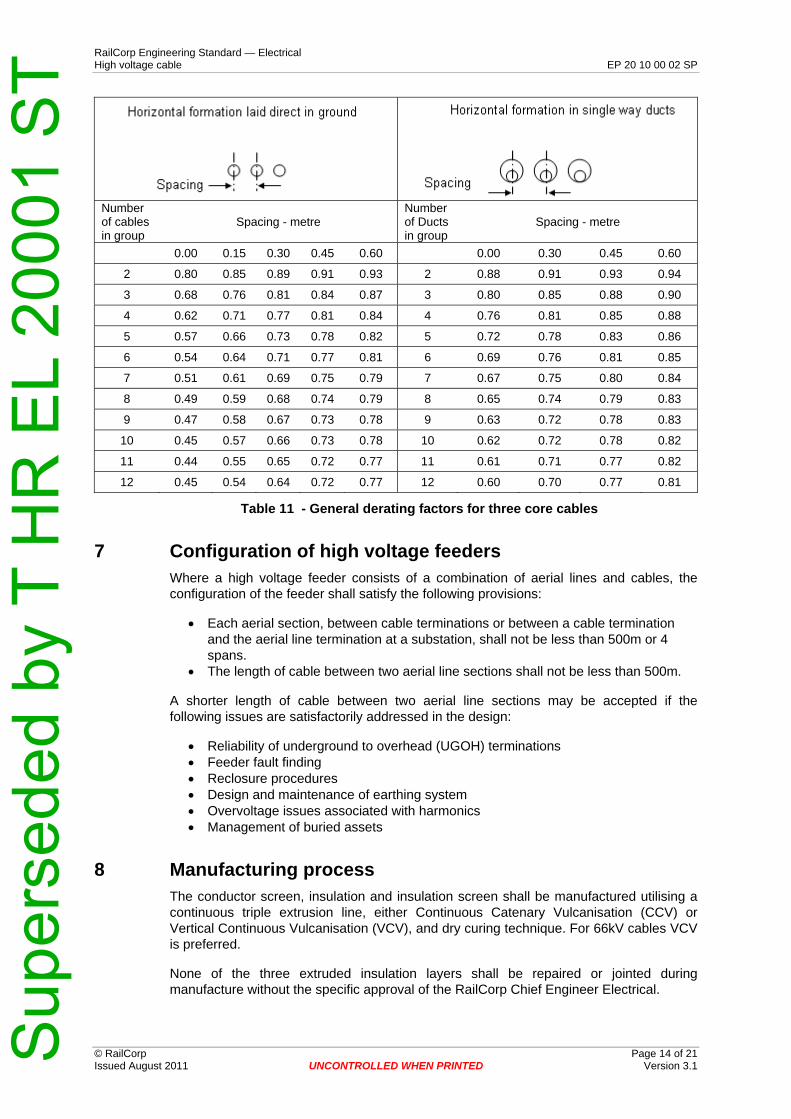
Number Number of cables in group
Spacing - metre of Ducts in group
Spacing - metre
0.00 0.15 0.30 0.45 0.60 0.00 0.30 0.45 0.60
2 0.80 0.85 0.89 0.91 0.93 2 0.88 0.91 0.93 0.94
3 0.68 0.76 0.81 0.84 0.87 3 0.80 0.85 0.88 0.90
4 0.62 0.71 0.77 0.81 0.84 4 0.76 0.81 0.85 0.88
5 0.57 0.66 0.73 0.78 0.82 5 0.72 0.78 0.83 0.86
6 0.54 0.64 0.71 0.77 0.81 6 0.69 0.76 0.81 0.85
7 0.51 0.61 0.69 0.75 0.79 7 0.67 0.75 0.80 0.84
8 0.49 0.59 0.68 0.74 0.79 8 0.65 0.74 0.79 0.83
9 0.47 0.58 0.67 0.73 0.78 9 0.63 0.72 0.78 0.83
10 0.45 0.57 0.66 0.73 0.78 10 0.62 0.72 0.78 0.82
11 0.44 0.55 0.65 0.72 0.77 11 0.61 0.71 0.77 0.82
12 0.45 0.54 0.64 0.72 0.77 12 0.60 0.70 0.77 0.81
Table 11 - General derating factors for three core cables
7 Configuration of high voltage feeders Where a high voltage feeder consists of a combination of aerial lines and cables, the configuration of the feeder shall satisfy the following provisions:
• Each aerial section, between cable terminations or between a cable termination and the aerial line termination at a substation, shall not be less than 500m or 4 spans.
• The length of cable between two aerial line sections shall not be less than 500m.
A shorter length of cable between two aerial line sections may be accepted if the following issues are satisfactorily addressed in the design:
• Reliability of underground to overhead (UGOH) terminations • Feeder fault finding • Reclosure procedures • Design and maintenance of earthing system • Overvoltage issues associated with harmonics • Management of buried assets
8 Manufacturing process The conductor screen, insulation and insulation screen shall be manufactured utilising a continuous triple extrusion line, either Continuous Catenary Vulcanisation (CCV) or Vertical Continuous Vulcanisation (VCV), and dry curing technique. For 66kV cables VCV is preferred.
None of the three extruded insulation layers shall be repaired or jointed during manufacture without the specific approval of the RailCorp Chief Engineer Electrical.
© RailCorp Page 14 of 21 Issued August 2011 UNCONTROLLED WHEN PRINTED Version 3.1
Sup
erse
ded
by T
HR
EL
2000
1 S
T RailCorp Engineering Standard — Electrical High voltage cable EP 20 10 00 02 SP
9 Cables for use in tunnels or underground stations
© RailCorp Page 15 of 21 Issued August 2011 UNCONTROLLED WHEN PRINTED Version 3.1
Cables for use in tunnels or underground stations shall have a low smoke, low toxicity, halogen free non-metallic oversheath including a flame retardant outer sheath suitable for installation in damp situations.
The flame retardant outer sheath shall comply with AS/NZS 1660.5.2:2006, AS/NZS 1660.5.4:1998 and AS/NZS 1660.5.6:2005.
The cable itself shall be to classification RHE in accordance with AS/NZS 4507:2006.
Cable installation shall comply with the provisions of ESC 340.
It is preferred that the flame retardant outer sheath be of a material that is cross linkable in the extrusion process – thereby providing added protection against mechanical damage and water penetration.
The oversheath assembly shall not contain PVC or other halogen producing materials.
For single core cables, with or without a metal sheath, the oversheath assembly shall comprise an HDPE inner sheath followed by flame retardant outer sheath.
For three core cables without metal sheath there shall in addition be provided a halogen free innermost sheath so as to comply with the provision of AS/NZS 1429.1 Section 2.13.1(d).
10 Integrated optic fibres for temperature monitoring Optic fibres are used where temperature monitoring of cable is required via the concept of “distributed temperature sensing” (DTS).
Optic fibres integrated within the structure of a power cable are able to more accurately track cable temperature as opposed to optic fibres located in some form outside the cable.
Integrated optic fibres represent a small incremental cost for sub-transmission cable (33kV and higher) and with on-going developments in associated detectors – together with other optic fibre applications (sensing of pressures & other parameters – as well as applications in communication, protection & general data transfer) it is appropriate to maximise opportunity by diversifying the type of fibre to be installed and maximising the number of fibres – all within the context of practicality.
Accordingly a minimum of 6 fibres comprising the following shall be specified:
• 2 x 50/125 multi mode fibres • 2 x 62.5/125 multi mode fibres • 2 x 10/125 single mode fibres
The three fibre types shall be distinguishable by colour or other approved means.
In single core cables optic fibres are generally located within a protective tube located between adjacent screen wires – so as to provide some protection against crushing forces. In three core cables a similar arrangement of fibres & protective tube is generally laid up within the cable.
Cables with a nominal voltage of 33kV and above shall be provided with integrated optic fibres for temperature monitoring for new installations with the following conditions:
• Where the cable connects to a traction substation and the length of cable is greater than 100m
Sup
erse
ded
by T
HR
EL
2000
1 S
T RailCorp Engineering Standard — Electrical High voltage cable EP 20 10 00 02 SP
© RailCorp Page 16 of 21 Issued August 2011 UNCONTROLLED WHEN PRINTED Version 3.1
• Where the cable is to be installed between two aerial sections of a high voltage feeder and the cable length is 500m or greater.
Optic fibres for temperature sensing are not required for cables with a nominal voltage of 11kV and below.
11 Inspection & Testing The equipment shall comply in all respects with the requirements of this document. All tests shall be done by laboratories with NATA or equivalent accreditation.
11.1 Type tests
Type tests shall be performed, or type test certificates provided, in accordance with AS/NZS 1429.1:2006 or 1429.2:2009 (as applicable to voltage rating).
11.2 Routine tests
Routine tests shall be performed in accordance with AS/NZS 1429.1:2006 or 1429.2:2009 (as applicable to voltage rating).
11.3 Sample tests
Sample tests shall be performed in accordance with AS/NZS 1429.1:2006 or 1429.2:2009 (as applicable to voltage rating).
11.4 Test certificates and Qualification test report
A Qualification test report and test certificates covering all type, sample and routine tests shall be provided by the supplier. The test report and certificates shall be supplied, in duplicate and electronically, and are to be in English.
12 Data set associated with the cable(s) The following data shall be supplied by the manufacturer and maintained for each type and conductor size of cable. This data will remain the property of RailCorp.
12.1 Drawings and Information
The following drawings are required:
• A detailed drawing (to scale) showing the cross section of the cable and identifying the individual layers of the cable and including a detailed description of the layers with associated dimension adjacent.
• A cross section of the cable (to scale) showing the location of the optic fibres with special reference to the means of protection against crushing forces.
• A cross section of the optic fibre protective packaging showing location of the fibres within the packaging and describing all components
12.2 Test results
The Qualification test report and test certificates shall be maintained for the life of the cable.
Sup
erse
ded
by T
HR
EL
2000
1 S
T RailCorp EngiHigh voltage c
12.3 Technical Schedule
neering Standard — Electrical able EP 20 10 00 02 SP
The information listed in the technical schedule of Appendix A, from the successful tenderer, shall be maintained for each cable type and conductor size.
© RailCorp Page 17 of 21 Issued August 2011 UNCONTROLLED WHEN PRINTED Version 3.1

Sup
erse
ded
by T
HR
EL
2000
1 S
T RailCorp Engineering Standard — Electrical High voltage cable EP 20 10 00 02 SP
© RailCorp Page 18 of 21 Issued August 2011 UNCONTROLLED WHEN PRINTED Version 3.1
Appendix A Technical Schedule (Information to be provided by Tenderers)
The information and guaranteed performance figures listed below shall be supplied with the tender for each type and size of cable.
Manufacturer ___________________
Manufacturing plant address ___________________
Cable type ___________________
Conductor material ___________________ copper
Conductor stranding (No/mm) ___________________
Compacted or compressed ___________________
Overall conductor diameter ___________________ mm
Cross sectional area ___________________ 2mm
Insulation material ___________________
Radial thickness of insulation (excluding semi-conducting layers ___________________ mm
Details of conductor semi-conducting layer ___________________
Details of insulation semi-conducting layer ___________________
Details of line and curing method ___________________
Details of longitudinal water blocking system (where ___________________ specified)
Details of metallic sheath (where specified) ___________________
Details of screen ___________________
Wires stranding ___________________ No/mm
Cross sectional area ___________________ mm²
Approximate coverage ___________________ %
Details of oversheath (materials and minimum thicknesses) including flame retardant sheath:
__________________________________________________________
__________________________________________________________
Cable overall diameter ___________________ mm
Cable mass ___________________ kg/100m
Minimum bending radius adjacent to joints & terminations ___________________ m
Maximum allowable pulling tension via stockinette ___________________ Newtons
Cable BIL __________________ kV
Maximum conductor operating temperature ___________________
Normal ___________________ °C
Emergency (2 hour) ___________________ °C
Short circuit ___________________ °C
Maximum DC resistance of conductor of completed cable at 20°C ___________________ Ohms/km
Sup
erse
ded
by T
HR
EL
2000
1 S
T RailCorp Engineering Standard — Electrical High voltage cable EP 20 10 00 02 SP
© RailCorp Page 19 of 21 Issued August 2011 UNCONTROLLED WHEN PRINTED Version 3.1
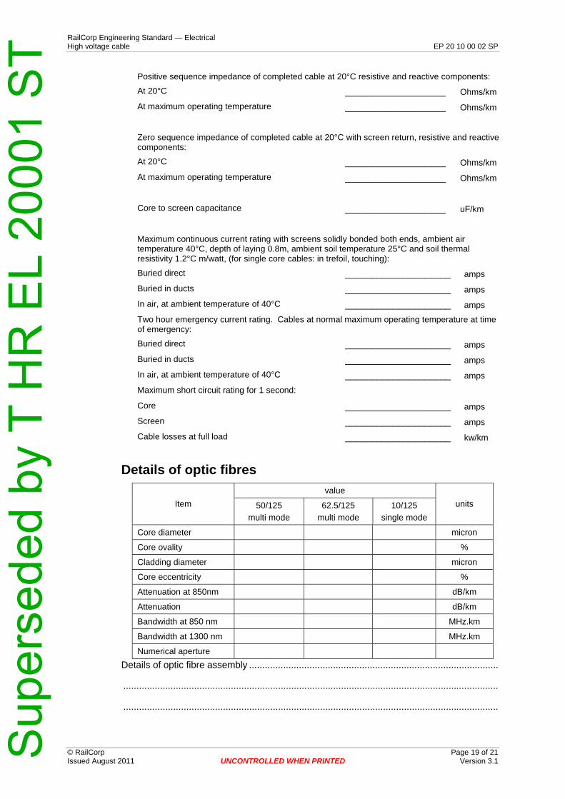
Positive sequence impedance of completed cable at 20°C resistive and reactive components:
At 20°C ___________________ Ohms/km
At maximum operating temperature ___________________ Ohms/km
Zero sequence impedance of completed cable at 20°C with screen return, resistive and reactive components:
At 20°C ___________________ Ohms/km
At maximum operating temperature ___________________ Ohms/km
Core to screen capacitance ___________________ uF/km
Maximum continuous current rating with screens solidly bonded both ends, ambient air temperature 40°C, depth of laying 0.8m, ambient soil temperature 25°C and soil thermal resistivity 1.2°C m/watt, (for single core cables: in trefoil, touching):
Buried direct ____________________ amps
Buried in ducts ____________________ amps
In air, at ambient temperature of 40°C ____________________ amps
Two hour emergency current rating. Cables at normal maximum operating temperature at time of emergency:
Buried direct ____________________ amps
Buried in ducts ____________________ amps
In air, at ambient temperature of 40°C ____________________ amps
Maximum short circuit rating for 1 second:
Core ____________________ amps
Screen ____________________ amps
Cable losses at full load ____________________ kw/km
Details of optic fibres
value
Item 50/125 62.5/125 10/125 units
multi mode multi mode single mode
Core diameter micron
Core ovality %
Cladding diameter micron
Core eccentricity %
Attenuation at 850nm dB/km
Attenuation dB/km
Bandwidth at 850 nm MHz.km
Bandwidth at 1300 nm MHz.km
Numerical aperture
Details of optic ............................ fibre assembly ...................................................................
...............................................................................................................................................
...............................................................................................................................................
Sup
erse
ded
by T
HR
EL
2000
1 S
T RailCorp Engineering Standard — Electrical High voltage cable EP 20 10 00 02 SP
© RailCorp Page 20 of 21 Issued August 2011 UNCONTROLLED WHEN PRINTED Version 3.1
Appendix B Cable drums and preparation for delivery The cable shall be wound onto wooden or steel drums and prepared for deliver – all in accordance with the requirements of AS/NZS 1429.1:2006 or AS/NZS 1429.2:2009, as appropriate.
Wooden drums are preferred; however, steel drums may be necessary in the following situations:
• where additional mechanical protection is required for example, where cable is delivered from overseas inside a shipping container
• where cable will be stored in the open for extended periods for example, spare stock • where cable will be “paid out” utilising a motorised cradle, or other device requiring
smooth drum rims
Cable drums shall have an overall diameter of not more than 2.8 metres and width of not more than 2.0 metres unless otherwise agreed.
The drum shall have a round spindle hole of minimum 125 mm diameter.
The cable shall be protected by wooden battens or approved equivalent. “COREFLUTE” is not acceptable.
The order number, length of cable, weight, size and type of cable shall be painted on each drum.
Total weight of cable drum plus cable shall not exceed 20 Tonnes (Currently Chullora Store has 20T and 10T cranes. Off loading facilities directly at work site need also to be considered).
Drum ownership
Ownership of cable drums shall be determined on a case by case basis for example,
Drums shall become the property of the Purchaser where cable is destined to go into store as general stock for an indefinite period.
Drums shall become the property of the Supplier (and shall be retrieved by the Supplier at its cost as and when determined by the Purchaser) where cable is destined for project work where cable will be installed in quick time.

Sup
erse
ded
by T
HR
EL
2000
1 S
T RailCorp Engineering Standard — Electrical High voltage cable EP 20 10 00 02 SP
© RailCorp Page 21 of 21 Issued August 2011 UNCONTROLLED WHEN PRINTED Version 3.1
Appendix C Request for Tender - Check List
Information to be supplied to tenderers
For each type and conductor size of cable required the following information shall be provided to tenderers:
• Voltage rating • Conductor size (mm²) • Insulation • Cable construction (see Section 5) • Flame retardant oversheath requirement (see Section 9) • Integrated optic fibres requirement (see Section 10) • Total length requirement • Preferred cable length per drum • Delivery location • Delivery date • Details of cable drums, total weight limitations and (if it matters) whether wooden or
steel drums (see Appendix B) • A statement regarding cable drum ownership arrangement (see Appendix B) • Requirement for a pulling eye, fitted to the conductor, on the cable end (if needed) • A statement stipulating that type testing and routine testing will be at the suppliers
cost and that the purchaser reserves the right to witness tests carried out • A statement stipulating that the purchaser reserves the right to inspect the cables at
any time during the manufacturing process
Information to be supplied by tenderers
For each type and conductor size of cable required the following information shall be provided by tenderers:
• Completed Technical Schedule (see Appendix A) • Drawings (see Section 12.1) • Type test certificates and Qualification test report • If the cables are intended for manufacture in a plant not previously inspected by the
Purchaser the tender price shall include travel & accommodation costs for a Purchaser representative to inspect the plant.
• Details of manufacturer’s quality management system • Proposed delivery schedule
Information to be supplied by the successful tenderer
Cable production plan
A cable production plan shall be provided within two weeks of receipt of order. The plan to show milestones (dates & times commencing from receipt of order) of all intermediate processes (including manufacture and testing) through to cable delivery.
Test Certificates
Copies of certified test certificates and Qualification test reports covering type tests, routine tests and sample tests shall be provided prior to delivery of the cables.