Environmental Assessment and Prepared for DC … · Environmental Assessment and Management Plan...
113
TE14019-DC_Recycling_EAMP.2a Environmental Assessment and Management Plan Inert Recycling Facility Prepared for DC Recycling February 2015 | Page 52 Appendix F: Noise Assessment
Transcript of Environmental Assessment and Prepared for DC … · Environmental Assessment and Management Plan...

TE14019-DC_Recycling_EAMP.2a
Environmental Assessment and Management Plan Inert Recycling Facility Prepared for DC Recycling
February 2015 | Page 52
Appendix F: Noise Assessment

Dowsing Concrete
Noise Emissions Compliance of Inert Material
Crushing Activity
Assessment Report
16 FEB 2015

Sealhurst.com.au
ABN 086 161 563 551 ACN 161 563 551
PO BOX 1082, BALCATTA, WA 6914
DOCUMENT INFORMATION
© SEALHURST PTY LTD All Rights Reserved
QA INFORMATION
Project No SEA-2013-028
Project Name Dowsing Inert Recycling Facility
Client Dowsing Concrete
Report Title Acoustics - Noise Emissions Compliance of Inert Material Crushing Activity
Filename SEA-2013-028 RPT001
Revision [Category]
Reason For Issue Client Comment
Authorised By
Issue Date 12 FEB 2015
Dowsing Concrete
Dowsing Inert Recycling Facility
Acoustics - Noise Emissions Compliance of Inert Material Crushing
Activity

Sealhurst.com.au
ABN 086 161 563 551 ACN 161 563 551
PO BOX 1082, BALCATTA, WA 6914
DOCUMENT INFORMATION
© SEALHURST PTY LTD All Rights Reserved
PROJECT PARTNERS
Discipline Entity
Client Dowsing Concrete
Lead Consultant TALIS Consultants

Dowsing Inert Recycling Facility Acoustics - Noise Emissions Compliance of Inert Material Crushing Activity
EXECUTIVE SUMMARY
© SEALHURST PTY LTD All Rights Reserved SEA-2013-028 RPT001 i
EXECUTIVE SUMMARY
Sealhurst were appointed by TALIS Consultants (on behalf of their client, Dowsing Concrete) to provide acoustic
assessment, modelling and design consultancy relating to “Phase 2” operations at the Dowsing Inert Recycling
Facility, proposed to be constructed on Berkshire Road in FORRESTFIELD, Western Australia.
Phase 1 operations relate to delivery and storage of inert material in preparation for Phase 2 operations, which
relates to the crushing of inert material into recycled material for to produce more sustainable environmental
building products. This formal report presents detailed assessment and compliance advice on the use of a
preferred enclosure design for Client Comment issue - a summary of our report findings are presented below:
NOISE MITIGATION
A detailed study of proposed operations has been undertaken in consultation with Dowsing Concrete and lead
consultant TALIS Consultants in order to determine a feasible and practical noise mitigation strategy for crushing
screening processing of inert materials at the Berkshire Road site.
A series of noise mitigation options and scenarios have been investigated – the final preferred course of selected
mitigation is comprised the construction of a 5m 3 –sided enclosure to an area of the processing yard where
crushing and screening operations will take place. Crusher screening plant will be fed from higher level via
excavator on an earth ramp – indicative arrangement shown in Section 4.7.3.
COMPLIANCE STATEMENT
In assessment of processing of inert material at Dowsing Concrete’s proposed facility on Berkshire Road,
processing operations are determined to be able to comply with the Assigned Noise Level limits (adjusted for
tonality -5dB(A)) applicable at the identified NSR, agreed as the Caretaker residence property, (deemed to be
“Industrial” as per DER direction), when undertaken with a 5m, 3-sided enclosure wall around the
“PROCESSING” area of the facility.
Noise prediction modelling indicates noise emissions received at all site boundaries under this scenario will also
be able to comply, save for a minor exceedence at the northern-most boundary, to “Bush Forever” land.
Further recommendations are presented, with noise monitoring recommended post-completion to demonstrate
the as-built operation si able to comply with predicted noise levels.

Dowsing Inert Recycling Facility Acoustics - Noise Emissions Compliance of Inert Material Crushing Activity
TABLE OF CONTENTS
© SEALHURST PTY LTD All Rights Reserved SEA-2013-028 RPT001 ii
TABLE OF CONTENTS
EXECUTIVE SUMMARY ..........................................................................................................................i 1 INTRODUCTION ........................................................................................................................ 1-1
1.1 General Appreciation .................................................................................................................................. 1-1
1.1.1 Progress to Date...................................................................................................................................... 1-1 1.1.2 Phase 1 – Compliant Noise Emission Operations Summary .................................................................... 1-1 1.1.3 Phase 2 – Operations to Be Assessed ..................................................................................................... 1-1 1.1.4 Report Aims ............................................................................................................................................. 1-2
1.2 Project Inputs .............................................................................................................................................. 1-2
1.2.1 Concept Drawings, Operational Plan, Equipment Data .......................................................................... 1-2
2 PROJECT CONTEXT .................................................................................................................. 2-1
2.1 Development Definition .............................................................................................................................. 2-1
2.1.1 Proposed Development .......................................................................................................................... 2-1 2.1.2 Site Location and Surrounds.................................................................................................................... 2-1
3 NOISE EMISSIONS TO ENVIRONMENT ..................................................................................... 3-2
3.1 Applicable Criteria....................................................................................................................................... 3-2
3.1.1 Environmental Protection (Noise) Regulations (1997) ............................................................................. 3-2 3.1.2 Identification of Nearest Noise-Sensitive Receiver (NSR)........................................................................ 3-2 3.1.3 Separation Distance to NSR .................................................................................................................... 3-3 3.1.4 Noise Source Character ........................................................................................................................... 3-3 3.1.5 Applied Penalties .................................................................................................................................... 3-3
3.2 Assessment Methodology ........................................................................................................................... 3-3
3.2.1 Detailed Prediction Modelling of Processing .......................................................................................... 3-3
4 SITE LAYOUT, EQUIPMENT & INPUT SOURCE NOISE LEVELS .................................................. 4-4
4.1 Site Layout ................................................................................................................................................... 4-4
4.1.1 Proposed Processing Operations ............................................................................................................ 4-4
4.2 Crushing Plant & Processing Equipment ..................................................................................................... 4-5
4.2.1 Tracked Excavator ................................................................................................................................... 4-5 4.2.2 TEREX Powerscreen XR400S Jaw Crusher .............................................................................................. 4-5 4.2.3 TEREX Powerscreen XH320X Horizontal Impactor ................................................................................. 4-5
4.3 Input Source Noise Levels ........................................................................................................................... 4-5 4.4 Preliminary Assessment Model – Base Inputs, No Mitigation ..................................................................... 4-6
4.4.1 Site Layout ............................................................................................................................................... 4-6 4.4.2 Environment Noise Modelling Parameters .............................................................................................. 4-6 4.4.3 Preliminary Assessment Model – Results................................................................................................. 4-7
4.5 Iterations of Design ..................................................................................................................................... 4-7
4.5.1 Potential Mitigation Options ................................................................................................................... 4-7 4.5.2 Summary Table of Modelled Mitigation and Resultant Outputs ............................................................. 4-8 4.5.3 Developing Compliant Operations ......................................................................................................... 4-9

Dowsing Inert Recycling Facility Acoustics - Noise Emissions Compliance of Inert Material Crushing Activity
TABLE OF CONTENTS
© SEALHURST PTY LTD All Rights Reserved SEA-2013-028 RPT001 iii
4.6 Assessing Actual Sound Power from Excavator Operations ..................................................................... 4-10
4.6.1 Reference Database Sound Power Input............................................................................................... 4-10
4.7 Sound Power Measurements of Proposed Excavator CAT 392D [EX02] .................................................. 4-10
4.7.1 Site Measurement Methodology ........................................................................................................... 4-10 4.7.2 Results ................................................................................................................................................... 4-11 4.7.3 Amended Noise Mitigation – Client Input and Approach ..................................................................... 4-11
5 FINAL OPERATIONS MODEL ..................................................................................................... 5-1
5.1 Mitigation & Measured Input Data Results ................................................................................................. 5-1
5.1.1 Final Operations Model - Results ............................................................................................................ 5-1
5.2 Compliance Statement ................................................................................................................................ 5-1
5.2.1 Final Operations Model – Interpreting Results & Compliance Statement .............................................. 5-1 5.2.2 Further Recommendations ...................................................................................................................... 5-2
A. PHASE 1 – BASIS OF COMPLIANCE & PREVIOUS REPORTS ..................................................... 5-1
A.1 SEA-2013-028 LTR001_Rev1 ....................................................................................................................... 5-1 A.2 SEA-2013-028 LTR002 ................................................................................................................................. 5-2 A.3 SEA-2013-028 LTR003_Rev1 ....................................................................................................................... 5-3
B. CALCULATION OF NOISE EMISSIONS LIMITS........................................................................... 5-1 C. PROPOSED CRUSHING EQUIPMENT & OPERATIONS PLAN .................................................... 5-1
C.1 Site Plan & Operations Layout .................................................................................................................... 5-1 C.2 Ref: LPE301150 Dowsing Concrete Recyclers – Plant Setup #1 ................................................................. 5-2 C.3 Proposed Plant Equipment ......................................................................................................................... 5-3
D. EQUIPMENT CALIBRATION CERTIFICATES ............................................................................... 5-1 E. NOISE DURING CONSTRUCTION PHASE .................................................................................. 5-1
E.1 Extract from Appendix D AS 2436 - Section 4.6 ......................................................................................... 5-1
F. ACOUSTIC GLOSSARY .............................................................................................................. 5-1

Dowsing Inert Recycling Facility Acoustics - Noise Emissions Compliance of Inert Material Crushing Activity
1 INTRODUCTION
© SEALHURST PTY LTD All Rights Reserved SEA-2013-028 RPT001 1-1
1 INTRODUCTION
1.1 General Appreciation
1.1.1 Progress to Date
Sealhurst were appointed by TALIS Consultants (on behalf of their client, Dowsing Concrete) to provide acoustic
assessment, modelling and design consultancy relating to compliance with environmental noise emissions limits
for proposed operations from activities at the Dowsing Inert Recycling Facility, proposed to be constructed on
Berkshire Road in FORRESTFIELD, Western Australia.
The project has been addressed at previous planning application stages, in 2013-2014, with operational activities
and consequent noise emissions considered in two phases:
“Phase 1” operations relate to unloading and storage of inert building materials via articulated road
transport in preparation for processing; And,
“Phase 2” operations, which includes the crushing of inert material into recycled material intended to
produce sustainable environmental building products.
1.1.2 Phase 1 – Compliant Noise Emission Operations Summary
Phase 1 noise emissions assessments and the development of compliance criteria were provided in previously
submitted works (SEA-2013-028 LTR001_Rev1, SEA-2013-028 LTR002 and SEA-2013-028 LTR003_Rev1), included
in Appendix A. The findings and compliant operations plan identified therein was reviewed and accepted by
DER through a process of detailed consultation on the basis of:
An agreed fixed limit of 65dB LA10 (adjusted to 60dB LA10 for tonality) at the nearest noise sensitive
receiver premises (NSR), identified as an Industrial “caretaker residence” property, on the adjacent
property, addressed as 257 Berkshire Road, FORRESTFIELD WA;
Time-limited (24 minute) allowance for operation of material delivery trucks (once on site) passing the
NSR at a nearest distance of 12m within any given 4 hour period of fixed items of plant with associated
noise emission profile(s) WITH additional 5dB(A) penalty applied for tonality; And,
Movement of inert material into rubble piles using an 8t Skid Steer wheeled loader from Dowsing’s
vehicle inventory at distances greater than 29m from the NSR.
1.1.3 Phase 2 – Operations to Be Assessed
Phase 2 noise emissions are characterised by the addition of mobile crushing and screening plant to an identified
“Processing” area, shown green on Site Layout Plan (Ref: TE14019DG001), see Appendix C.
We understand that specific crushing and screening plant will be provided as follows, (See Appendix C):
Powerscreen XR400 S
Powerscreen XH320 S; And,
Tracked Excavator
The combined crushing screening operation is for inert material to be fed into crushing plant hopper at high level
via tracked excavator, from which material will pass through the crushing/screening plant body, to be output into
stockpiles via crushing/screening plant conveyor belt, ready for storage.
Equipment, noise data and operational details for the processing have been provided by Dowsing Concrete.

Dowsing Inert Recycling Facility Acoustics - Noise Emissions Compliance of Inert Material Crushing Activity
1 INTRODUCTION
© SEALHURST PTY LTD All Rights Reserved SEA-2013-028 RPT001 1-2
1.1.4 Report Aims
Our report is intended to collate crushing and screening process data in terms of noise emissions, assess
predicted noise emissions based upon the input data, and determine compliance with the applicable State
legislation. In the case where noise emissions from crushing are predicted to exceed the applicable limits,
requirement(s) and method(s) of mitigation to achieve the applicable limits are presented.
1.2 Project Inputs
1.2.1 Concept Drawings, Operational Plan, Equipment Data
The assessment has been carried out based upon the latest available concept drawings, operational plan and
proposed equipment data supplied by TALIS Consultants, on behalf of the Principal client, Dowsing Concrete.
Design advice contained in this report to achieve environmental noise emissions compliance (where required) is
based upon this documentation - details are current at the date of this report (12 FEB 2015).

Dowsing Inert Recycling Facility Acoustics - Noise Emissions Compliance of Inert Material Crushing Activity
2 PROJECT CONTEXT
© SEALHURST PTY LTD All Rights Reserved SEA-2013-028 RPT001 2-1
2 PROJECT CONTEXT
2.1 Development Definition
2.1.1 Proposed Development
Dowsing Concrete propose to develop an inert materials processing facility at their development site, addressed
at 261 Berkshire Road Industrial Estate, in the FORRESTFIELD/HIGHWYCOMBE area of WA.
The facility will be used to store and process inert materials,
which we understand to be (typically) spent or demolished
rubble from existing buildings, and conduct recycling
processing to refine and convert waste materials into
components suitable for the production of new,
sustainably-produced building materials.
The facility will encompass delivery, loading/unloading,
storage and processing elements, as well as house a
workshop/warehouse and administrative office building.
Delivery trucks are to enter and depart the site using an
efficient one way system to minimise use of reverse
beepers (if required), and access is possible to the site from
Berkshire Road (primary site entry) and rear laneway to the
north east boundary of the site.
2.1.2 Site Location and Surrounds
The schematic image of the site shown above (Ref: Appendix C for more details)
is roughly 360m at its longest aspect and approx. 60m at the Berkshire Road
entrance. Neighbouring sites on the north side of Berkshire Road are cleared
land for sale, or are currently undergoing industrial type construction and
development.
Existing property and land uses to the south side of Berkshire Road are primarily
existing industrial, warehouse, transport and logistics uses, with a high
percentage heavy vehicle road traffic passing along Berkshire Road, connecting
Roe Highway and Dundas Road.
We understand the site is located within a larger area of land currently
undergoing major change, gazetted to the local planning scheme via formal
amendment to re-classify as a light industrial zone, allowing the establishment
and development of a centralised and dedicated logistics and transportation
precinct with excellent access to existing State primary road infrastructure.
This report is intended to appreciate and assess the requirement to control noise
to adjacent land classified “Industrial” use, and to demonstrate the proposed
operations are able to meet the applicable noise emissions criteria once
operational at the proposed site.
Dowsing Inert Recycling Facility Acoustics - Noise Emissions Compliance of Inert Material Crushing Activity
3 NOISE EMISSIONS TO ENVIRONMENT
© SEALHURST PTY LTD All Rights Reserved SEA-2013-028 RPT001 3-2
3 NOISE EMISSIONS TO ENVIRONMENT
3.1 Applicable Criteria
3.1.1 Environmental Protection (Noise) Regulations (1997)
All sources of noise introduced as part of a new or refurbished development, must be demonstrated to comply
with the noise emissions limits applicable under Western Australian State Environmental Law.
The Environmental Protection (Noise) Regulations 1997 (inc amendments) is the applicable legislative instrument
governing all sources of noise emissions, through the application of noise emission limits, referred as “Assigned
Noise Level” (ANL) limits, applicable at the nearest noise-receiving property.
The Regulations1997 prescribe a specific methodology from which to calculate the ANL, which is based upon an
appraisal of the percentage of Commercial (C) and Industrial (I) land use surrounding the nearest noise sensitive
receiver (NSR), and the volume and composition of road traffic in the vicinity of two concentric radii drawn at
450m (outer) and 100m (inner) boundary areas surrounding the designated NSR.
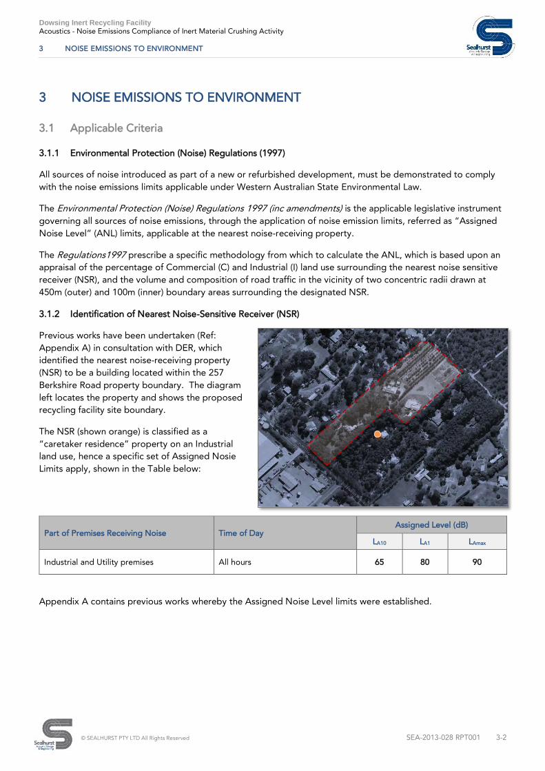
3.1.2 Identification of Nearest Noise-Sensitive Receiver (NSR)
Previous works have been undertaken (Ref:
Appendix A) in consultation with DER, which
identified the nearest noise-receiving property
(NSR) to be a building located within the 257
Berkshire Road property boundary. The diagram
left locates the property and shows the proposed
recycling facility site boundary.
The NSR (shown orange) is classified as a
“caretaker residence” property on an Industrial
land use, hence a specific set of Assigned Nosie
Limits apply, shown in the Table below:
Appendix A contains previous works whereby the Assigned Noise Level limits were established.
Part of Premises Receiving Noise Time of Day
Assigned Level (dB)
LA10 LA1 LAmax
Industrial and Utility premises All hours 65 80 90

Dowsing Inert Recycling Facility Acoustics - Noise Emissions Compliance of Inert Material Crushing Activity
3 NOISE EMISSIONS TO ENVIRONMENT
© SEALHURST PTY LTD All Rights Reserved SEA-2013-028 RPT001 3-3
3.1.3 Separation Distance to NSR
A separation distance of approx. 12m exists between the nearest property boundary to the caretaker residence
building.
In order to determine compliance with the Assigned Noise Level (ANL) calculation for processing operations, the
identified (nearest) NSR is taken to be the point of compliance. Assessment has also been considered at each
site boundary in order to ensure compliance with potential future industrial neighbouring properties.
3.1.4 Noise Source Character
In addition to the ANL limits, particular noise sources can attract additional punitive dB levies based upon the
noise source characteristics. Regulation 7 prescribes that the noise character must be "free" of annoying
characteristics - specifically:
(i) tonality (e.g. whining, droning)
(ii) modulation (e.g. cyclical change in character, such as a siren)
(iii) impulsiveness (e.g. banging, thumping)
Penalties apply up to a maximum of +15dB, for tonality (+5dB), modulation (+5dB) and impulsiveness (+10dB),
where the noise source is NOT music.
3.1.5 Applied Penalties
Phase 1 works was attributed a +5dB penalty for tonality, due to anticipated noise associated with inert material
delivery trucks passing by the caretaker residence.
Phase 2 works have been assessed with a similar +5dB penalty in mind, associated with the engine noise from
crushing/screening plant and tracked excavator feed – noise sources and general understanding of the proposed
crushing/screening operations is covered in Section 4.
3.2 Assessment Methodology
3.2.1 Detailed Prediction Modelling of Processing
Given the range of noise and noise sources, it was determined that a detailed prediction model of the proposed
process would be the most efficient way to assess noise emissions and noise mitigation, if found to be required.
Noise modelling offers the opportunity to investigate a number of processing scenarios, based upon the realistic
function of proposed operations at the site. Detailed input was provided by Dowsing in terms of equipment
layout, on and off times of equipment, durations and anticipated load.
Section 4 details site layout, proposed operations and introduces processing plant and data used to predict likely
noise impacts from processing. Subsequent compliance is derived from comparison of predicted levels at the
site boundary with the ANL limits (inclusive of penalties) defined above.

Dowsing Inert Recycling Facility Acoustics - Noise Emissions Compliance of Inert Material Crushing Activity
4 SITE LAYOUT, EQUIPMENT & INPUT SOURCE NOISE LEVELS
© SEALHURST PTY LTD All Rights Reserved SEA-2013-028 RPT001 4-4
4 SITE LAYOUT, EQUIPMENT & INPUT SOURCE NOISE LEVELS
4.1 Site Layout
4.1.1 Proposed Processing Operations
The site schematic below demonstrates the proposed flow of inert material from acceptance, processing and
storage via a one-way truck loop, accessed from Berkshire Road:
Our understanding of a typical processing operation can be summarised as follows:
1. Laden dump trucks enter site at western entry, passing inspection platform, following one-way loop to
material “ACCEPTANCE” area, indicated yellow on schematic site plan above. Trucks then unload
rubble as appropriate in preparation for processing operations;
2. Crushing and screening plant equipment will be located in the central “PROCESSING” area, indicated
green on the schematic site plan above. A single tracked excavator will be used to load a rubber-lined
“hopper” feeding into the crushing and screening plant, which will process inert material feed (building
rubble) into finer grade material, exported from crushing screening plant via extended conveyor belt;
3. Once processed, material suitable for use in sustainable building products will be stockpiled in the
“RECYCLED PRODUCT” area, indicated purple on the schematic site plan above.

Dowsing Inert Recycling Facility Acoustics - Noise Emissions Compliance of Inert Material Crushing Activity
4 SITE LAYOUT, EQUIPMENT & INPUT SOURCE NOISE LEVELS
© SEALHURST PTY LTD All Rights Reserved SEA-2013-028 RPT001 4-5
4.2 Crushing Plant & Processing Equipment
Specialist equipment is required to undertake the crushing and screening element of the inert material
processing operation. The following equipment details have been supplied by Dowsing Concrete as
representative of the plant setup. Reference drawings and process information for the proposed setup is
included in Appendix C:
4.2.1 Tracked Excavator
As per steps 1 – 3 in Section 4.1.1, once inert material is accepted, a tracked excavator will
load the crushing screening plant via elevated hopper. We understand the tracked
excavator EX02 is to be used, from Dowsing Concrete existing inventory. Part of the
acoustic study for this project involved a series of specific noise measurements, taken of this
item of equipment undertaking loading of inert material to increase accuracy and reliability
of predicted noise levels from plant operations – details in Section 4.6.
4.2.2 TEREX Powerscreen XR400S Jaw Crusher
Detailed information has been provided for the TEREX Powerscreen XR400S jaw crusher,
to undertake the initial phase of the two-stage processing of inert material (Ref.
Appendix C.2). We understand from operations information that the jaw crusher is the
marginally smaller of two TEREX units when operating at ~15m in length, 4.3m wide and
up to 4.1m at working height.
Full plant details are included in Appendix C.2 as referenced input informations.
4.2.3 TEREX Powerscreen XH320X Horizontal Impactor
Detailed information has been provided for the TEREX Powerscreen XR400S jaw crusher,
to undertake the initial phase of the two-stage processing of inert material (Ref. Appendix
C.2). The unit is up to 16m in length, 8.6m wide and up to 4.5m in height when operating
with lateral conveyor attached.
Full plant details are included in Appendix C.2 as referenced input informations.
4.3 Input Source Noise Levels
Critical data for any prediction noise model is objective and reliable sound power data for each plant equipment
item and process. The table below presents octave band sound power levels for each processing plant item used
in preliminary prediction modelling. Where manufacturer noise levels were considered, reference noise data
from the DEFRA UK national reference database for similar process equipment was used to ensure representative
noise emissions were accounted for:
Item
Octave Band Sound Power Level (dB)
63 125 250 500 1kHz 2kHz 4kHz 8kHz dB(A) dB(lin)
TEREX Powerscreen XR400S 72.0 92.0 97.0 100.0 106.0 97.0 93.0 85.0 108.0 112.6
TEREX Powerscreen XH320X 72.0 92.0 95.0 99.0 105.0 97.0 93.0 84.0 107.1 111.9
Tracked Excavator (Clearing Site)
(Ref: DEFRA Database)
108.0 111.0 104.0 101.0 100.0 98.0 97.0 94.0 105.9 114.0
Tracked Excavator (Loading Truck)
Ref: DEFRA Database)
110.0 106.0 110.0 109.0 109.0 106.0 100.0 92.0 113.0 116.5
Dowsing Inert Recycling Facility Acoustics - Noise Emissions Compliance of Inert Material Crushing Activity
4 SITE LAYOUT, EQUIPMENT & INPUT SOURCE NOISE LEVELS
© SEALHURST PTY LTD All Rights Reserved SEA-2013-028 RPT001 4-6
4.4 Preliminary Assessment Model – Base Inputs, No Mitigation
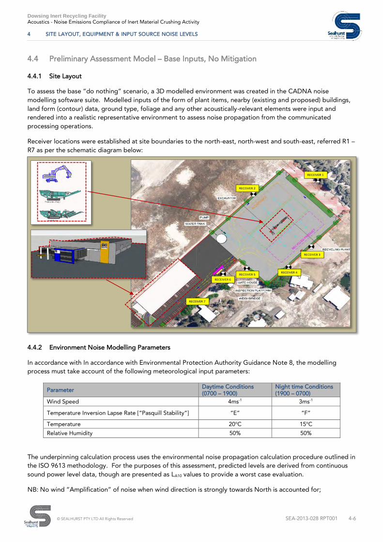
4.4.1 Site Layout
To assess the base “do nothing” scenario, a 3D modelled environment was created in the CADNA noise
modelling software suite. Modelled inputs of the form of plant items, nearby (existing and proposed) buildings,
land form (contour) data, ground type, foliage and any other acoustically-relevant elements were input and
rendered into a realistic representative environment to assess noise propagation from the communicated
processing operations.
Receiver locations were established at site boundaries to the north-east, north-west and south-east, referred R1 –
R7 as per the schematic diagram below:
4.4.2 Environment Noise Modelling Parameters
In accordance with In accordance with Environmental Protection Authority Guidance Note 8, the modelling
process must take account of the following meteorological input parameters:
Parameter Daytime Conditions
(0700 – 1900)
Night time Conditions
(1900 – 0700)
Wind Speed 4ms-1
3ms-1
Temperature Inversion Lapse Rate [“Pasquill Stability”] “E” “F”
Temperature 20o
C 15o
C
Relative Humidity 50% 50%
The underpinning calculation process uses the environmental noise propagation calculation procedure outlined in
the ISO 9613 methodology. For the purposes of this assessment, predicted levels are derived from continuous
sound power level data, though are presented as LA10 values to provide a worst case evaluation.
NB: No wind “Amplification” of noise when wind direction is strongly towards North is accounted for;

Dowsing Inert Recycling Facility Acoustics - Noise Emissions Compliance of Inert Material Crushing Activity
4 SITE LAYOUT, EQUIPMENT & INPUT SOURCE NOISE LEVELS
© SEALHURST PTY LTD All Rights Reserved SEA-2013-028 RPT001 4-7
4.4.3 Preliminary Assessment Model – Results
Noise emissions from crushing screening plant and tracked excavator operations are anticipated to exceed the
applicable Assigned Noise Level (ANL) limits, adjusted for tonality penalties, of LA10 60dB. The table below
presents predicted results at each noted Receiver Location (1 – 7):
NB Receiver Location 6 is representative of the site boundary conditions adjacent to the Caretaker Residence
property, identified in Section 3.1.2 on 257 Berkshire Road, and the principle location of compliance assessed in
this report.
Receiver
Ref. No.
Location ID
Predicted
Level
(dB(A))
EPA Regulation Limits Receiver Coordinates
LA10
(dB(A))
Penalty
(dB(A))
Resultant
LA10
(dB(A))
X (m) Y (m) Z (m)
REC1 Bush Forever Boundary 62.6 65.0 -5.0 60.0 50405530.49 6463068.68 1.50
REC 2 North-west Boundary 66.8 65.0 -5.0 60.0 50405440.82 6463046.71 1.50
REC 3 South-east Boundary (1 of 4) 67.2 65.0 -5.0 60.0 50405521.19 6462964.40 1.50
REC 4 South-east Boundary (2 of 4) 66.7 65.0 -5.0 60.0 50405489.48 6462932.51 1.50
REC 5 South-east Boundary (3 of 4) 65.7 65.0 -5.0 60.0 50405431.43 6462930.46 1.50
REC 6 Adjacent to Caretaker Property [NSR] 62.5 65.0 -5.0 60.0 50405398.55 6462921.72 1.50
REC 7 South-east Boundary (4 of 4) 58.0 65.0 -5.0 60.0 50405364.84 6462876.90 1.50
4.5 Iterations of Design
4.5.1 Potential Mitigation Options
In terms of design from noise mitigation, the modelled environment offers a unique and efficient methodology to
identify primary contributions of noise at the receiver iteratively assess potential mitigation options in order to
find the most appropriate project solution.
The principle site layout was determined during Phase 1 and accommodates compliance of truck noise as passing
by the Caretaker Residence NSR (Rec 6). A wide range of measures were assessed for noise reduction
performance, practicality, suitability to practical processing operational requirements, truck and plant mobility
safety, practicality, feasibility and project cost.
Modelled attenuation measures assessed as follows:
1. 3m, 4m 5m, 3-sided barrier enclosure to crushing screening plant, no roof;
2. Perimeter barrier to 60m x 30m “PROCESSING” area, no roof;
3. Removal of earth to lower “PROCESSING” area ground level by 3m;
4. As (3) supplemented with 3m, 4m 5m barrier enclosure to perimeter of “PROCESSING” area, no roof;
5. Shifting of Primary “PROCESSING” location north towards Bush Forever reserve;
6. 5m 3-sided barrier enclosure with access ramp for excavator;

Dowsing Inert Recycling Facility Acoustics - Noise Emissions Compliance of Inert Material Crushing Activity
4 SITE LAYOUT, EQUIPMENT & INPUT SOURCE NOISE LEVELS
© SEALHURST PTY LTD All Rights Reserved SEA-2013-028 RPT001 4-8
4.5.2 Summary Table of Modelled Mitigation and Resultant Outputs
Model Ref. Mitigation Elements
Excavator
Source Input
(dB (lin))
Result @ NSR (Rec 6)
LIMIT
(dB(A))
Predicted
(dB(A)) RESULT
Rev1 Sc. 01 None; 116.5dB 60.0 62.5 DOES NOT
COMPLY
Rev1 Sc. 02 None; 114.0dB 60.0 58.9 PARTIAL
COMPLIANCE*
Rev1 Sc. 03
5m, 3-sided enclosure around crusher plant;
Excavator operating OUTSIDE enclosure 116.5dB 60.0 63.4
DOES NOT
COMPLY
Rev1 Sc. 04
5m, 3-sided enclosure around crusher plant;
Excavator operating OUTSIDE enclosure; 114.0dB 60.0 57.1
PARTIAL
COMPLIANCE*
Rev1 Sc. 05
Ground area in “PROCESSING” lowered by 3m to
form bunded area; Excavator operating OUTSIDE
enclosure;
116.5dB 60.0 61.3
DOES NOT
COMPLY
Rev1 Sc. 06
Ground area in “PROCESSING” lowered by 3m to
form bunded area; Excavator operating OUTSIDE
enclosure;
114.0dB 60.0 58.2
PARTIAL
COMPLIANCE*
Rev1 Sc. 07
Ground area in “PROCESSING” lowered by 3m to
form bunded area PLUS 3m 3-sided enclosure to
crushing screening plant; Excavator operating
OUTSIDE enclosure;
114.0dB 60.0 52.7 COMPLIES**
Rev1 Sc. 08
Ground area in “PROCESSING” lowered by 3m to
form bunded area PLUS 3m 3-sided enclosure to
crushing screening plant; Excavator operating
OUTSIDE enclosure;
116.5dB 60.0 54.3 COMPLIES**
Rev1 Sc. 09
Shifted crushing screening operations zone North;
No enclosure; 116.5dB 60.0 59.5
PARTIAL
COMPLIANCE*
Rev1 Sc. 10
Shifted crushing screening operations zone North;
5m 3-sided enclosure around crusher plant;
Excavator operating OUTSIDE enclosure;
116.5dB 60.0 60.3 DOES NOT
COMPLY
Rev1 Sc. 11 5m, 3-sided enclosure around crusher screening
operations AND Excavator;
116.5dB 60.0 56.3 PARTIAL
COMPLIANCE*
Rev1 Sc. 12
5m, 3-sided *REDUCED PROCESSING AREA*
enclosure around crusher screening operations
AND Excavator;
116.5dB 60.0 55.7
PARTIAL
COMPLIANCE*
Rev1 Sc. 13
Fully Enclosed Building 6m Height inc. crusher
screening AND Excavator; Non-absorptive
construction, no ventilation openings
116.5dB 60.0 53.5 COMPLIES
Rev1 Sc. 14 No Enclosure, No Excavator n/a 60.0 57.5
PARTIAL
COMPLIANCE*
Rev1 Sc. 15 No Excavator, 5m 3-sided enclosure around
crusher screening plant;
n/a 60.0 51.6 COMPLIES**
Rev1 Sc. 16
5m 3-sided enclosure around crusher screening
plant; Reduced Noise Excavator operating
OUTSIDE enclosure; Use of earth access ramp to
load crusher screening plant
105.8dB 60.0 53.5 COMPLIES**
Dowsing Inert Recycling Facility Acoustics - Noise Emissions Compliance of Inert Material Crushing Activity
4 SITE LAYOUT, EQUIPMENT & INPUT SOURCE NOISE LEVELS
© SEALHURST PTY LTD All Rights Reserved SEA-2013-028 RPT001 4-9
NOTE
* - Predicted noise emissions demonstrate PARTIAL COMPLIANCE at NSR (Receiver 6) but do not comply
at ALL site boundary receiver locations;
** - Predicted noise emissions COMPLY at all receivers, save for minor exceedance (<1dB(A)) at “Bush
Forever” site boundary (Receiver 1) (e.g. no physical noise-sensitive receivers present);
Scenarios - waffle text to show many avenues were sought:
4.5.3 Developing Compliant Operations
During the course of extensive detailed modelling of noise emissions over Scenarios 1 – 16 patterns of
exceedence became apparent, with the following areas examined:
SOURCE HEIGHTS
Source heights for crushing screening plant are allocated at 4.1m as determined during analysis of proposed
plant equipment and operational use of crushing machinery. The effective source height significantly reduced
enclosures of heights below 4m, rendering lower height barriers as ineffective when assessed at boundary
receiver locations at 1.5m above ground level.
Increasing the height of barriers increases wind loading/resistance requirements, safety and cost parameters,
hence an alternative was sought to improve attenuation.
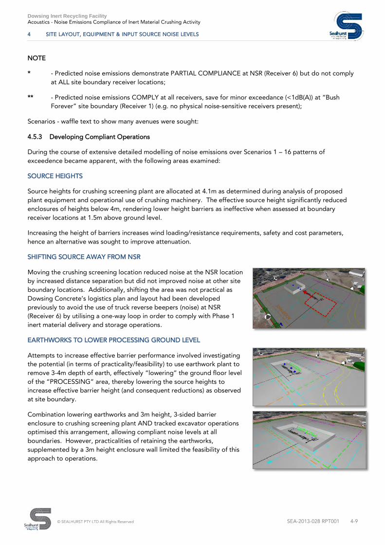
SHIFTING SOURCE AWAY FROM NSR
Moving the crushing screening location reduced noise at the NSR location
by increased distance separation but did not improved noise at other site
boundary locations. Additionally, shifting the area was not practical as
Dowsing Concrete’s logistics plan and layout had been developed
previously to avoid the use of truck reverse beepers (noise) at NSR
(Receiver 6) by utilising a one-way loop in order to comply with Phase 1
inert material delivery and storage operations.
EARTHWORKS TO LOWER PROCESSING GROUND LEVEL
Attempts to increase effective barrier performance involved investigating
the potential (in terms of practicality/feasibility) to use earthwork plant to
remove 3-4m depth of earth, effectively “lowering” the ground floor level
of the “PROCESSING” area, thereby lowering the source heights to
increase effective barrier height (and consequent reductions) as observed
at site boundary.
Combination lowering earthworks and 3m height, 3-sided barrier
enclosure to crushing screening plant AND tracked excavator operations
optimised this arrangement, allowing compliant noise levels at all
boundaries. However, practicalities of retaining the earthworks,
supplemented by a 3m height enclosure wall limited the feasibility of this
approach to operations.

Dowsing Inert Recycling Facility Acoustics - Noise Emissions Compliance of Inert Material Crushing Activity
4 SITE LAYOUT, EQUIPMENT & INPUT SOURCE NOISE LEVELS
© SEALHURST PTY LTD All Rights Reserved SEA-2013-028 RPT001 4-10
4.6 Assessing Actual Sound Power from Excavator Operations
4.6.1 Reference Database Sound Power Input
Particular variance in predicted noise level and resultant compliance was observed in terms of input tracked
excavator noise used in each model scenario. Reviewing predicted results showed in a number of scenarios,
crushing and screening plant noise emissions were able to comply with ANL limits at the site boundary alone.
It was found that specific impact upon ANL-compliant operations (e.g. non-compliance) could be determined as
noise contributions emanating from the specific excavator sound power data used in predictions. Further
research indicated that excavator size, load, motor power rating, material drop height were all variables affecting
sound power.
Initial models use tracked excavator sound power data for tracked excavators significantly larger in size than the
proposed excavator to be used at Berkshire Road. It was therefore determined that measurements would be
taken of the proposed specific excavator unit to be used, thus determining actual sound power levels from sound
pressure measurements, in accordance with ISO 3746:1996 Acoustics – Determination of sound power levels of
noise sources using sound pressure – Survey method using an enveloping measurement surface over a reflecting
plane.
This approach allows the model to more accurately predict resultant noise emissions from excavator noise
emissions, at Rec’s 1- 7, and at the NSR.
4.7 Sound Power Measurements of Proposed Excavator CAT 392D [EX02]
4.7.1 Site Measurement Methodology
Sealhurst attended site Friday 6th
February 2015 to
determine appropriate sound power input data for
prediction modelling of excavator noise. Dowsing
Concrete provided a tracked excavator model CAT
392D (Ref: EX02”) and dump truck to simulate precise
rubble loading operations, Ref: images (right).
Several source conditions were assessed - Excavator
idling; Excvator and dump truck idling; Excavator
loading inert material into dump truck; Excavator
unloading inert material from dump truck to stock pile
nearby. Sound pressure level measurements were
taken at 8 key microphone positions on radial points of
a hemisphere of 5m radius at appropriate heights to
account for spherical surface. 5m was chosen for
safety reasons, with measured sound pressures
representative of the source operations only.
Background noise levels were >10dB(A) lower than
measurements taken in proximity to operational plant
equipment. Environmental conditions were calm with
no discernible wind, and no precipitation during
measurements.
Reference details of the measurement methodology are contained in Annex B of ISO 3746:1996.

Dowsing Inert Recycling Facility Acoustics - Noise Emissions Compliance of Inert Material Crushing Activity
4 SITE LAYOUT, EQUIPMENT & INPUT SOURCE NOISE LEVELS
© SEALHURST PTY LTD All Rights Reserved SEA-2013-028 RPT001 4-11
4.7.2 Results
Measured sound level data was processed in accordance with the methodology described under ISO 3746:1996
to determine actual sound power level spectrum. Results are presented in the table below, presented with
preliminary modelling sound power level data for comparison:
Item
Octave Band Sound Power Level (dB)
63 125 250 500 1kHz 2kHz 4kHz 8kHz dB(A) dB(lin)
CAT 329D “EX02” SWL as
determined in accordance with ISO
3746:1996
102.0 98.1 95.5 99.0 95.9 93.4 90.7 84.6 101.1 106.2
Tracked Excavator (Clearing Site)
(Ref: DEFRA Database) 108.0 111.0 104.0 101.0 100.0 98.0 97.0 94.0 105.9 114.0
Tracked Excavator (Loading Truck)
Ref: DEFRA Database) 110.0 106.0 110.0 109.0 109.0 106.0 100.0 92.0 113.0 116.5
As is evident, actual sound power levels of the CAT 392D are significantly lower than those of larger excavator
plant contained within DEFRA reference database used in preliminary modelling assessment. As could be
expected, predicted noise findings in the preliminary analysis demonstrated the excavator noise source, located
outside of any proposed enclosures, had a significant effect upon compliance at particular site boundaries. Use
of lower sound power emissions is anticipated as having two outcomes:
(i) Positive benefit to the amended prediction model in terms of reduced level(s);
(ii) Increased accuracy/reliability in predictions, by demonstration of best practice in terms of obtaining
correct data;
Actual sound power data for CAT 392D excavator above was subsequently added in as source data to the
amended noise emissions model.
4.7.3 Amended Noise Mitigation – Client Input and Approach
In consultation with lead consultant, TALIS, proposed noise mitigation was discussed. During data collection and
analysis for sound power adjustments, Dowsing Concrete undertook a process of consolidation of proposed
noise mitigation measures in order to select an appropriate solution for processing operations, acknowledging
impacts upon effectiveness, safety, feasibility, practicality of operations, time and cost.
The final preferred mitigation selection was determined based upon practicality and feasibility, as follows:
(i) 5m, 3-sided enclosure in original “PROCESSING” area location;
(ii) Sound power data for CAT 392D excavator input as source data;
(iii) Earthen ramp to be created to allow excavator access to hopper;
The image (right) shows the arrangement in the modelled
environment, with sources shown as blue cross icons. Source
heights are at 4.1m for crushing screening plant, and 7m for
excavator plant;

Dowsing Inert Recycling Facility
Acoustics - Noise Emissions Compliance of Inert Material Crushing Activity
5 FINAL OPERATIONS MODEL
© SEALHURST PTY LTD All Rights Reserved SEA-2013-028 RPT001 5-1
5 FINAL OPERATIONS MODEL
5.1 Mitigation & Measured Input Data Results
5.1.1 Final Operations Model - Results
Noise emissions from crushing screening plant and tracked excavator operations are anticipated to comply with
the applicable Assigned Noise Level (ANL) limits, adjusted for tonality penalties, of LA10 60dB. The table below
presents predicted results at each noted Receiver Location (1 – 7):
Receiver
Ref. No.
Location ID
Predicted
Level
(dB(A))
EPA Regulation Limits Receiver Coordinates
LA10
(dB(A))
Penalty
(dB(A))
Resultant
LA10
(dB(A))
X (m) Y (m) Z (m)
REC1 Bush Forever Boundary 61.2 65.0 -5.0 60.0 50405530.49 6463068.68 1.50
REC 2 North-west Boundary 59.0 65.0 -5.0 60.0 50405440.82 6463046.71 1.50
REC 3 South-east Boundary (1 of 4) 59.0 65.0 -5.0 60.0 50405521.19 6462964.40 1.50
REC 4 South-east Boundary (2 of 4) 58.4 65.0 -5.0 60.0 50405489.48 6462932.51 1.50
REC 5 South-east Boundary (3 of 4) 56.2 65.0 -5.0 60.0 50405431.43 6462930.46 1.50
REC 6 Adjacent to Caretaker Property [NSR] 53.5 65.0 -5.0 60.0 50405398.55 6462921.72 1.50
REC 7 South-east Boundary (4 of 4) 49.8 65.0 -5.0 60.0 50405364.84 6462876.90 1.50
NB Receiver Location 6 is representative of the site boundary conditions adjacent to the Caretaker Residence,
identified in Section 3.1.2 as 257 Berkshire Road, and the principle location of compliance assessed in this report.
5.2 Compliance Statement
5.2.1 Final Operations Model – Interpreting Results & Compliance Statement
In assessment of processing of inert material at Dowsing Concrete’s proposed facility on Berkshire Road,
processing operations are determined to be able to comply with the Assigned Noise Level limits (adjusted for
tonality -5dB(A)) applicable at the Caretaker residence property, (deemed to be “Industrial” as per DER
direction), when undertaken with a 5m, 3-sided enclosure wall around the “PROCESSING” area of the facility.
Noise prediction modelling indicates noise emissions received at all site boundaries under this scenario will also
be able to comply, save for a minor exceedence at the northern-most boundary, to “Bush Forever” land.
It is important to understand the predicted noise levels are based upon fixed sound power levels as reported –
processing operations are anticipated to be functioning at certain times of the day and will not be “on” at all
times – such as is deemed to occur at construction sites.
Compliance is therefore presented as a “worst case” with all sources operating.
It is also important to understand that Compliance does not infer inaudible – as should be expected, activity
noise will be audible, within the agreed applicable limits.

Dowsing Inert Recycling Facility
Acoustics - Noise Emissions Compliance of Inert Material Crushing Activity
5 FINAL OPERATIONS MODEL
© SEALHURST PTY LTD All Rights Reserved SEA-2013-028 RPT001 5-2
5.2.2 Further Recommendations
In order to ensure operations are able to comply in the as-built facility, we would recommend a period of noise
monitoring post-completion. Any changes to the proposed schedule of processing equipment should be
assessed for potential impacts to noise emissions as are currently predicted. Sound power levels used in this
assessment should be considered as a “maximum” level, against which any future or replacement equipment may
be judged – lower sound power level emissions would imply compliant operations.

Dowsing Inert Recycling Facility
Acoustics - Noise Emissions Compliance of Inert Material Crushing Activity
A PHASE 1 – BASIS OF COMPLIANCE & PREVIOUS REPORTS
© SEALHURST PTY LTD All Rights Reserved SEA-2013-028 RPT001
A. PHASE 1 – BASIS OF COMPLIANCE & PREVIOUS REPORTS
A.1 SEA-2013-028 LTR001_Rev1
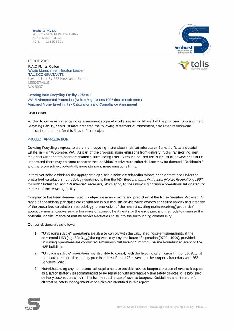
SEA-2013-028 LTR001 - Dowsing Inert Recycling Facility - Phase 1
Sealhurst Pty LtdPO Box 704, W PERTH, WA 6872ABN: 86 161 563 551ACN: 161 563 551
16 OCT 2013
Dowsing Inert Recycling Facility - Phase 1WA Environmental Protection (Noise) Regulations 1997 (inc amendments)Assigned Noise Level limits - Calculations and Compliance Assessment
Dear Ronan,
Further to our environmental noise assessment scope of works, regarding Phase 1 of the proposed Dowsing InertRecycling Facility, Sealhurst have prepared the following statement of assessment, calculated result(s) andimplication outcomes for this Phase of the project.
PROJECT APPRECIATION
Dowsing Recycling propose to store inert recycling materials at their Lot address on Berkshire Road IndustrialEstate, in High Wycombe, WA. As part of the proposal, noise emissions from delivery trucks transporting inertmaterials will generate noise emissions to surrounding Lots. Surrounding land use is industrial, however Sealhurstunderstand there may be some concerns that individual receivers on Industrial Lots may be deemed "Residential"and therefore subject potentially more stringent noise emissions limits.
In terms of noise emissions, the appropriate applicable noise emissions limits have been determined under theprescribed calculation methodology contained within the WA Environmental Protection (Noise) Regulations 1997for both "Industrial" and "Residential" receivers, which apply to the unloading of rubble operations anticipated forPhase 1 of the recycling facility.
Compliance has been demonstrated via objective noise spectra and prediction at the Noise Sensitive Reciever. Arange of operational principles are considered in our acoustic advice which acknowledges the validity and integrityof the prescribed calculation methodology; preservation of the nearest existing (noise receiving) properties'acoustic amenity; cost-versus-performance of acoustic treatments for the enclosure; and methods to minimise thepotential for disturbance of routine services/activities noise into the surrounding commnunity.
Our conclusions are as follows:
1. "Unloading rubble" operations are able to comply with the calculated noise emissions limits at thenominated NSR (e.g. 60dBLA10) during weekday daytime hours of operation (0700 - 1900), providedunloading operations are conducted a minimum distance of 48m from the site boundary adjacent to theNSR building.
2. "Unloading rubble" operations are also able to comply with the fixed noise emission limit of 65dBLA10 atthe nearest industrial and utility premises, identified as 78m west, to the property boundary with 263,Berkshire Road.
3. Notwithstanding any non-acoustical requirement to provide reverse beepers, the use of reverse beepersas a safety strategy is recommended to be replaced with alternative visual safety devices, or establisheddelivery truck routes which minimise the routine use of reverse beepers. Guidelines and literature foralternative safety management of vehicles are identified in this report.
F.A.O Ronan CullenWaste Management Section LeaderTALIS CONSULTANTSLevel 1, Unit 8 / 663 Newcastle StreetLEEDERVILLEWA 6007

SEA-2013-028 LTR001 - Dowsing Inert Recycling Facility - Phase 1
Sealhurst Pty LtdPO Box 704, W PERTH, WA 6872ABN: 86 161 563 551ACN: 161 563 551
4. The immediate area surrounding the Site is zoned as Industrial Development according to the Shire ofKalamunda Local Planning Scheme No.3. This will increase the calculated Influencing Factor (IF), whenadjacent “neutral” land use Lots are developed for Industrial use(s).
The following pages present our calculation methodology and detailed recommendations to be incorporated intothe operational Phase as the project matures through the approvals process to practical completion.
If you have any queries, please feel free to contact me direct,
Kind Regards
Daryl ThompsonDirectorSealhurst Pty Ltd

SEA-2013-028 LTR001Dowsing Inert Recycling Facility - Phase 1Assigned Noise Level limits - Calculations and Compliance Assessment
SEA-2013-028 LTR001 - Dowsing Inert Recycling Facility - Phase 1
APPLICABLE CRITERIA
Environmental Protection (Noise) Regulations (1997)
The Environmental Protection (Noise) Regulations 1997 (inc amendments) is the applicable legislation governing allsources of noise emission which can be introduced when a new building or development is constructed; in this casenoise emissions from trucks unloading inert materials for storage at the proposed inert materials recycling facility.
The Regulations seek to regulate noise emission by the prescription of limits deemed "allowable" and applied at anidentified nearest Noise Sensitive Receiver (NSR). Schedule 3 of the Regulations prescribes a specificmethodology to calculate a set of Assigned Noise Level (ANL) limits, based upon standard values of "allowable"noise (e.g. 45dB LA10) PLUS the addition of an Influencing Factor (IF).
The "IF" accounts for any site specific circumstances surrounding the NSR, identified as part of the calculationprocess, and is formulated via a detailed appraisal of the percentage Commercial "C" and Industrial "I" land usewithin two concentric radii, at 450m (outer) and 100m (inner) distances surrounding the identified nearest NSR. ATransport Factor (TF) is also calculated to account for volume (AAWT) of road traffic in these two zones. Thecombined calculation provides a site-specific and practical relevance to each case.
Identification of Nearest Noise Sensitive Receiver (NSR)
When calculating an Assigned Noise Level(ANL) limit, a nearest noise-sensitive receivingpremises is selected, deemed to be thedefining receiving location for noise emissionsfrom a new development. Schedule 1 Part C,Environmental Protection (Noise) Regulations1997 prescribes the applicable definitions ofnoise sensitive premises.
The initial view and site appraisal showedsurrounding land to be 100% Industrial use, asverified by site inspection and photographs (seeAppendices). Consequently, all adjacent NSR'scould be deemed to be "Industrial". Underthese circumstances, the Assigned Noise levellimits are fixed under Schedule 3 of theRegulations and the ANL limits appliedaccording to TABLE 1, PART 2, clause (8).
However, we understand the current landowner is using this Lot for industrial purposes while leasing out theresidential property. Under the prescribed calculation methodology, residential receivers are deemed "noisesensitive", therefore the closest building which could be deemed to be noise sensitive has been identified as 257Berkshire Road, indicated above (orange). Furthermore, 257 Berkshire Road is currently on the market for sale forindustrial use, and is anticipated to be sold in the near future.”.
The area surrounding Dowsing Recycling's Lot on Berkshire Road remains predominantly "Industrial" use, though amore detailed calculation must now be undertaken. In order to maximise efficiency of any calculation(s), only thenearest NSR is considered during the assessment, with the implied logic that all receivers at greater distance(s) e.g.at any noise sensitive properties further from the inert material storage, will also comply with the Regulations.

SEA-2013-028 LTR001Dowsing Inert Recycling Facility - Phase 1Assigned Noise Level limits - Calculations and Compliance Assessment
SEA-2013-028 LTR001 - Dowsing Inert Recycling Facility - Phase 1
Application of Assigned Noise Level Limits
Under the prescribed calculation methodology, an Influencing Factor (IF) has been calculated as +15, determinedby the presence of Roe Highway (N of Berkshire Road) as a "Major" road1, within the 450m Outer circle; 58%Industrial Land Use* in the Inner Circle, and 72% Industrial Land Use* in the Outer Circle.
* Industrial Land Use was calculated using a combination of site observation, actual land use, geospatial datarecognition and planning mapping to determine land area(s) of particular identified uses. The predominant existingland use is almost entirely Industrial, with industrial construction developments in progress on a number of adjacentLots. Given the potential concerns for the adjacent Lot 257 Berkshire Road containing buildings deemed"residential", this land has been ascribed a "neutral" land use classification, thereby not included in the InfluencingFactor calculation.
The Influencing Factor (IF) is site-specific to this project and is added to the base value(s) to arrive at the AssignedNoise Level limits, applicable at the identified NSRs. In all cases where land use has been questioned, we haveerred on the side of conservatism and ascribed the land use as neutral. Land use mapping and percentage areadetails and all calculation inputs are presented in Technical Appendices at the end of this report.
The Table below presents the ANLs applicable to the nearest NSR:
Part of PremisesReceiving Noise
Time of DayAssigned Level (dB)
LA10 LA1 LAmax
Noise sensitive premisesat locations within 15m ofa building directlyassociated with a noisesensitive use
0700 to 1900 hours Monday to Saturday 60 70 80
0900 to 1900 hours Sundays and publicholidays
55 65 80
1900 to 2200 hours all days 55 65 70
2200 hours on any day to 0700 hoursMonday to Saturday and 0900 hoursSunday and public holidays
50 60 70
Noise sensitive premisesat locations further than15m of a building directlyassociated with a noisesensitive use
All hours 60 75 80
Commercial premises All hours 60 75 80
Industrial and Utilitypremises
All hours 65 80 90
1 "Major" roads as defined under WA Environmental Protection (Noise) Regulations 1997 (inc amendments) as having AAWTtraffic flows of >15,000 vehicles per day);

SEA-2013-028 LTR001Dowsing Inert Recycling Facility - Phase 1Assigned Noise Level limits - Calculations and Compliance Assessment
SEA-2013-028 LTR001 - Dowsing Inert Recycling Facility - Phase 1
Noise Source Character
In addition to the ANL limits, particular noise sources can attract additional punitive dB levies based upon the noisesource characteristics. Regulation 7 prescribes that the noise character must be "free" of annoying characteristics -specifically:
(i) tonality (e.g. whining, droning)(ii) modulation (e.g. cyclical change in character, such as a siren)(iii) impulsiveness (e.g. banging, thumping)
Penalties apply up to a maximum of +15dB, for tonality (+5dB), modulation (+5dB) and impulsiveness (+10dB),where the noise source is NOT music.
IDENTIFICATION AND ASSESSMENT OF IDENTIFIED NOISE SOURCE
Having established the limiting criteria applicable under statutory legislation, noise sources anticipated as part ofthe Phase 1 facility must now be identified and objectively assessed regarding compliance with the applicable noiselimits. The primary noise source associated with inert material storage proposed for Phase 1 has been identified as"unloading rubble" from delivery trucks.
Assessment of "Unloading Rubble"
Reference sound data was obtained from our construction noise source database for calculation. Sealhurst's noisedatabase references sound power level, and sound pressure level data from a range of measured data fromAustralian and International standards and guideline documents, designed to assist in noise planning matters. Thefollowing octave band noise spectra was obtained from the DEFRA (UK) construction noise database, item (11),which defines the following noise spectra and resultant sound pressure level data, used in our assessment:
(Ref No.) Equipment ItemSound Pressure Level (dB) Ref: Lp,10m
Octave Band Centre Frequency (Hz) (dBLin) LAeq,T
(dB)Brick Rubble 63 125 250 500 1000 2000 4000 8000
(11) Articulated Dump Truck 94 76 77 75 76 73 68 63 80
The subjective sound of "unloading rubble" is broadband, and can be likened to construction site-type noiseemissions, which are not usually subject to additional penalties when assessing compliance. An example would beduring construction noise management planning, unless a distinct tonal source is identified. Observations duringsite assessment revealed a number of intermittent noise sources attributable to existing industrial premises onBerkshire Road, as well as construction site noise at a number of industrial development construction sites currentlyactive in the vicinity.
Sealhurst have deemed it appropriate to attribute no additional penalties regards "unloading rubble" noise source,given the site and surroundings, existing premises noise emissions and current activities local to the Lot.

SEA-2013-028 LTR001Dowsing Inert Recycling Facility - Phase 1Assigned Noise Level limits - Calculations and Compliance Assessment
SEA-2013-028 LTR001 - Dowsing Inert Recycling Facility - Phase 1
TIMING AND FREQUENCY OF UNLOADING RUBBLE OPERATIONS
The proposed unloading operations will only be undertaken during day time hours (0700 - 1900), thereforeavoiding the potential for increased sensitivity (i.e. lower applicable limits) in the evening (1900-2200) and nighttime (2200-0700) hours, or weekend and public holidays.
Frequency of operations is yet to be determined, therefore individual unloading operations ONLY have beenassessed.
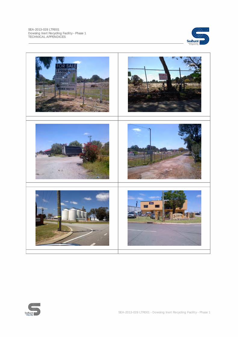
EXISTING ACOUSTIC CLIMATE
To provide a practical context and indication of the existingacoustic climate, Sealhurst attended site and conducted a seriesof noise measurements in locations representative of the existingNSR. Measurement positions are located in the images (right),which also show in greater detail the extent of Industrial land usein the area.
Senior engineering staff undertook measurements at varioustimes of the day, observing conditions and recording LAeq, LA10,LAMAX and LA90 values over consecutive 15-minute interval periods.
Noise sources were identified as road traffic along BerkshireRoad, and audible traffic from Roe Highway, some 350-400msouth-east of field measurement location(s); Construction sitenoise from Industrial buildings currently being erected onadjacent Lots between the Roe Highway and Dundas Road endsof Berkshire Road; And existing activities at the ThellmanWorldwide Logistics industrial premises immediately oppositefield measurement location(s).
Attended measurements were recorded using a Bruel & Kjaer
2260 Investigator Type 1 Sound Level Meter. The metercomplies with all relevant specification standards for Type 1integrating sound measurement equipment and was within avalid laboratory-calibration period at the time of survey. Themeter also satisfies all relevant and applicable AustralianStandards for acoustic measurement devices, including Schedule4 clauses contained within Environmental Protection (Noise)Regulations 1997.
The meter was field-calibrated before and after themeasurement series, which consisted of a number of 15minuninterrupted sample periods. All measurements were taken inaccordance with the relevant guidance in AS1055.1-1997:Acoustics – Description and Measurement of Environmental Noise, Part 1: General Procedures.
Details and calibration certificates of this equipment are included in the Technical Appendices of this report.

SEA-2013-028 LTR001Dowsing Inert Recycling Facility - Phase 1Assigned Noise Level limits - Calculations and Compliance Assessment
SEA-2013-028 LTR001 - Dowsing Inert Recycling Facility - Phase 1
MEASURED FIELD DATA
A summary of the broadband field measurement data is presented below:
Measurement Location Period LAeq,T(dB)
LA10(dB)
LA1(dB)
LAmax(dB)
Location #125m from Berkshire Road on boundarybetween Lots 257 and 253
Day time(0900-1100hrs)
61.4 65.0 73.0 76.6
Day time(1100-1300hrs)
64.5 69.0 74.2 78.8
Day time(1300-1500hrs)
57.9 60.0 69.8 74.9
NB Data is for a comparative reference only. Results in each identified daytime sub-period are averaged across anumber of measurements.
COMPLIANCE STATEMENT
Sealhurst have prepared a calculation model based upon the available information presented herein, taking aconservative account of surrounding geometry, barrier effect(s) between source and receiver, ground absorptionand meteorological input.
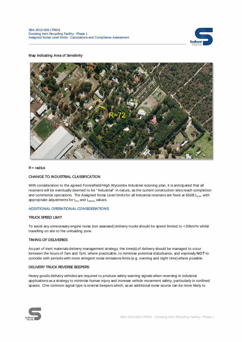
Our calculation model predicts that the unloading of inert recyclable rubble operations are able to comply withinthe identified Assigned Noise Level limits (60dBLA10) at the nearest NSR building identified at 257, Berkshire RoadIF operations are conducted a minimum distance of 48m from the site boundary adjacent to the "residential"building, creating an overall separation distance of 72m to the identified NSR, where the limit applies.
Compliance is based upon a predicted LAeq value of 50.8dB(A) from the unloading rubble noise source, at aminimum distance 72m from the NSR. The LAeq data is not directly comparable to the LA10 parameter per se, thoughby predicting a -9dB(A) at a minimum distance, this is a strong indication that compliance would be achieved in theabsence of proofing measurements. Site measurements of the documented intermittent construction site-typenoise sources show a difference of 3-4dB(A) between measured LAeq and LA10 therefore applying this principleindicates compliance.
A map is included over the page to demonstrate the 72m zone from the property, within which unloading rubble isnot recommended in order to meet the Regulations.
Our opinion and practical advice to retain noise emissions compliance during storage activities would be toestablish a designated rubble unloading area, for example towards the north west (rear) boundary of the Lot, awayfrom the "residential" NSR. Given the site and dimensions, an appropriate site planning exercise should beundertaken by Dowsing as part of the site development to ensure this minimum separation distance case is able tobe satisfied. This approach represents the most practical noise control at this stage of development.
At completion, a noise survey is recommended to determine compliance of a representative unloading operation todemonstrate this has been achieved.
SEA-2013-028 LTR001Dowsing Inert Recycling Facility - Phase 1Assigned Noise Level limits - Calculations and Compliance Assessment
SEA-2013-028 LTR001 - Dowsing Inert Recycling Facility - Phase 1
Map Indicating Area of Sensitivity
R = radius
CHANGE TO INDUSTRIAL CLASSIFICATION
With consideration to the agreed Forrestfield/High Wycombe Industrial rezoning plan, it is anticipated that allreceivers will be eventually deemed to be "Industrial" in nature, as the current construction sites reach completionand commence operations. The Assigned Noise Level limits for all Industrial receivers are fixed at 65dB LA10, withappropriate adjustments for LA1 and LAMAX values.
ADDITIONAL OPERATIONAL CONSIDERATIONS
TRUCK SPEED LIMIT
To avoid any unnecessary engine noise (not assessed) delivery trucks should be speed limited to <20km/hr whilsttravelling on site to the unloading zone.
TIMING OF DELIVERIES
As part of inert materials delivery management strategy, the time(s) of delivery should be managed to occurbetween the hours of 7am and 7pm, where practicable, to minimise potential disturbance, and expressly NOT tocoincide with periods with more stringent noise emissions limits (e.g. evening and night time) where possible.
DELIVERY TRUCK REVERSE BEEPERS
Heavy goods delivery vehicles are required to produce safety warning signals when reversing in industrialapplications as a strategy to minimise human injury and increase vehicle movement safety, particularly in confinedspaces. One common signal type is reverse beepers which, as an additional noise source can be more likely to

SEA-2013-028 LTR001Dowsing Inert Recycling Facility - Phase 1Assigned Noise Level limits - Calculations and Compliance Assessment
SEA-2013-028 LTR001 - Dowsing Inert Recycling Facility - Phase 1
cause annoyance and potential complaint, particularly at more noise-sensitive times i.e. evening and night timeperiods.
Regards reverse beepers, there exists a reasonable amount of literature[1], [2] regards alternative safety devices andmanagement principles which can be employed to avoid this precise acoustical issue - as the issue is one of safety(with an acoustical annoyance outcome), by removing the reverse beeper alarm source in place of an alternative(e.g. visual) alarm, the problem can be removed.
Such strategies are employed in existing high noise scenarios, where audio warnings have limited value - forexample high noise plant rooms, off shore installations etc where noise levels of warning sirens/signals may not beoverheard and/or could approach levels which would otherwise induce hearing damage in order to be heard.Typically staff in such areas may already be wearing ear defenders, therefore the principle is able to beimplemented where certain constraints apply.
The use of reversing cameras, visual alarms signals (e.g. specific vehicle reverse lights) and safety managementtechniques such as the use of spotters should be considered as part of the noise management strategy for thefacility. Alternatively, a delivery "loop" could be employed to ensure inert material delivery trucks do not routinelyemit "reverse beeper" noise, as this has not been assessed as a noise source.
TECHINCAL APPENDICES
The following pages present the detailed calculation methodology and input data used as part of our assessment.
[1] SAFE WORK AUSTRALIA - Draft guide Traffic Management: Construction Work;[2] ROADING NEW ZEALAND - Guideline for Controlling Reversing Vehicles DEC 2009;
SEA-2013-028 LTR001Dowsing Inert Recycling Facility - Phase 1TECHNICAL APPENDICES
SEA-2013-028 LTR001 - Dowsing Inert Recycling Facility - Phase 1
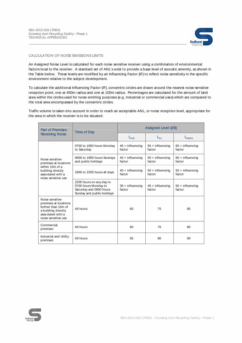
CALCULATION OF NOISE EMISSIONS LIMITS
An Assigned Noise Level is calculated for each noise sensitive receiver using a combination of environmentalfactors local to the receiver. A standard set of ANL’s exist to provide a base level of acoustic amenity, as shown inthe Table below. These levels are modified by an Influencing Factor (IF) to reflect noise sensitivity in the specificenvironment relative to the subject development.
To calculate the additional Influencing Factor (IF), concentric circles are drawn around the nearest noise-sensitivereception point; one at 450m radius and one at 100m radius. Percentages are calculated for the amount of landarea within the circles used for noise emitting purposes (e.g. industrial or commercial uses) which are compared tothe total area encompassed by the concentric circles.
Traffic volume is taken into account in order to reach an acceptable ANL, or noise reception level, appropriate forthe area in which the receiver is to be situated.
Part of PremisesReceiving Noise Time of Day
Assigned Level (dB)
LA10 LA1 LAMAX
Noise sensitivepremises at locationswithin 15m of abuilding directlyassociated with anoise sensitive use
0700 to 1900 hours Mondayto Saturday
45 + influencingfactor
55 + influencingfactor
65 + influencingfactor
0900 to 1900 hours Sundaysand public holidays
40 + influencingfactor
50 + influencingfactor
65 + influencingfactor
1900 to 2200 hours all days 40 + influencingfactor
50 + influencingfactor
55 + influencingfactor
2200 hours on any day to0700 hours Monday toSaturday and 0900 hoursSunday and public holidays
35 + influencingfactor
45 + influencingfactor
55 + influencingfactor
Noise sensitivepremises at locationsfurther than 15m ofa building directlyassociated with anoise sensitive use
All hours 60 75 80
Commercialpremises
All hours 60 75 80
Industrial and Utilitypremises
All hours 65 80 90

SEA-2013-028 LTR001Dowsing Inert Recycling Facility - Phase 1TECHNICAL APPENDICES
SEA-2013-028 LTR001 - Dowsing Inert Recycling Facility - Phase 1
CALCULATION OF INFLUENCING FACTOR (IF)
The Influencing Factor (IF) is calculated using the following equation:
Influencing factor (IF) = I + C + TFWhere;
I = (% of industrial land usage within 100m + %industrial land usage within 450m) x 1 / 10
C = (% of commercial land usage within 100m + %commercial land usage within 450m) x 1 / 20
TF = +6 if there is a "Major" road within 100m of the development +2 if there is a "Major" road within 450 m of the development + 2 if there is a "Secondary" road within 100m of the development
The maximum value the transport factor (TF) can reach is 6;
A "Major" road is defined as having Annual Average Weekday Traffic (AAWT) flows in excess of 15,000 vehiclemovements per day. A "Secondary" road is defined as having Annual Average Weekday Traffic (AAWT) flows inexcess of 6,000 vehicle movements per day.
IDENTIFICATION OF LAND USE
The image below shows our calculation of land use in the vicinity of the nearest Noise Sensitive Receiver (NSR),identified at the existing property at 257 Berkshire Road, High Wycombe. Confirmed Industrial land use in theOUTER circle is shown purple, and pink in the INNER (100m) circle; Roe Highway is classified as a Major Road andshown as red to the south-east of the development. No Commercial land use was identified.

SEA-2013-028 LTR001Dowsing Inert Recycling Facility - Phase 1TECHNICAL APPENDICES
SEA-2013-028 LTR001 - Dowsing Inert Recycling Facility - Phase 1
Land Use Type & IF Calculation
Industrial "I"
% Area in Inner Circle 58%
+12.95% Area in Outer Circle 72%
Commercial "C"
% Area in Inner Circle 0%
+0.00% Area in Outer Circle 0%
Roads LocationEstimated vehicleMovements per day
Classification Result "TF"
Roe Highway (N of Berkshire Road) Outer Circle 44,170 Major +2
2
INFLUENCING FACTOR +14.95
The resultant IF therefore equals 15, determining the Assigned Noise Level limits.

SEA-2013-028 LTR001Dowsing Inert Recycling Facility - Phase 1TECHNICAL APPENDICES
SEA-2013-028 LTR001 - Dowsing Inert Recycling Facility - Phase 1
SITE PHOTOGRAPHS

SEA-2013-028 LTR001Dowsing Inert Recycling Facility - Phase 1TECHNICAL APPENDICES
SEA-2013-028 LTR001 - Dowsing Inert Recycling Facility - Phase 1

SEA-2013-028 LTR001Dowsing Inert Recycling Facility - Phase 1TECHNICAL APPENDICES
SEA-2013-028 LTR001 - Dowsing Inert Recycling Facility - Phase 1

SEA-2013-028 LTR001Dowsing Inert Recycling Facility - Phase 1TECHNICAL APPENDICES
SEA-2013-028 LTR001 - Dowsing Inert Recycling Facility - Phase 1
SEA-2013-028 LTR001Dowsing Inert Recycling Facility - Phase 1TECHNICAL APPENDICES
SEA-2013-028 LTR001 - Dowsing Inert Recycling Facility - Phase 1

SEA-2013-028 LTR001Dowsing Inert Recycling Facility - Phase 1TECHNICAL APPENDICES
SEA-2013-028 LTR001 - Dowsing Inert Recycling Facility - Phase 1
FIELD MEASUREMENT EQUIPMENT DETAILS
EquipmentType/Model Serial No. Calibration Cert. No. Last Calibration
Date
Bruel & Kjaer 2260 2234562 SCC - C2159S1S118 17 JAN 2013
CIRRUS 59311 CCC - 1096C151 22 JAN 2013

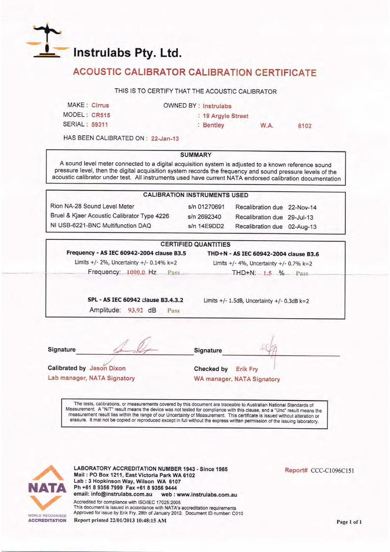

SEA-2013-028 LTR001Dowsing Inert Recycling Facility - Phase 1TECHNICAL APPENDICES
SEA-2013-028 LTR001 - Dowsing Inert Recycling Facility - Phase 1
PHASE 1 DEVELOPMENT APPLICATION - LAND STATUS

_̂
!.
_̂
!.
!.
!.
_̂
!.
!.
!.!.
!.
!.
!.
!.
!.
!.
!.
!.
!.
!.
!.
!.
!.
!.
!.
!.
!.
!.
!.
!.
!.!.
!.
!.
!.
!.
!.
!.
ROE HWY
BERKSHIRE RD
NARDINE CL
0
4
22
61
221
201
212
215
221
21
8
24
210
216
220
206
202
120
223
4
56
3
497
499
17
1615
62
11
9
218
207
64
223
220
204
2518
23
80
222
52
51
65
14
547
12
19
208 214
200
81
213
222
63
60
203
13
10
217
10
498
219
50
205
2
209
211
!(
Perth
Document Path: \\server\Talis\SECTIONS\Waste\PROJECTS\TW2013\TW13009 - Dowsing Approvals\GIS\Maps\7. Land Ownership\Figure 1 - Lot Status_RevB.mxd
0 50Kilometres
X.XXXXXXXXX.XXXXXXXX XXXXXXXX.XXXXXXXX
16/10/2013 A000/00 A Rev A
LEGEND
Figure 1Project No:
LAND STATUSPHASE 1 DEVELOPMENT APPLICATION
DC Recycling
0 200 400 600 800 1,000100Meters
±Coordinate System: GDA 1994 MGA Zone 50
Projection: Transverse Mercator, Datum: GDA 1994, Units: Meter
Reviewed:
Prepared:Checked:
1:7,000Date:Scale @ A3:
16/10/2013TS13009
_̂ Leased House!. Owner Occupied House
Roads200m BufferSite BoundaryCadastre
Sale StatusBush Forever SiteCurrently being developed for Industrial UseFor Sale for Industrial DevelopmentIndustrial Development by Current OwnerPurchased for Industrial DevelopmentSeeking ApprovalUnknownNo Residents/Vacant Block
R P CullenN KingR M Cullen

Dowsing Inert Recycling Facility
Acoustics - Noise Emissions Compliance of Inert Material Crushing Activity
A PHASE 1 – BASIS OF COMPLIANCE & PREVIOUS REPORTS
© SEALHURST PTY LTD All Rights Reserved SEA-2013-028 RPT001
A.2 SEA-2013-028 LTR002

SEA-2013-028 LTR002 - Dowsing Inert Recycling EIA (Noise)
Sealhurst Pty LtdPO Box 1082, BALCATTA, WA 6914ABN: 86 161 563 551ACN: 161 563 551
11th APR 2014
Dowsing Inert Recycling EIA (Noise) –WA Environmental Protection (Noise) Regulations 1997 (inc amendments)Assigned Noise Level Limits - Revised Response
Dear Ronan,
Following a detailed consultation process with DER, Sealhurst have prepared the following revised report settingout the basis of compliance with the Assigned Noise Level limits prescribed under the Environmental Protection(Noise) Regulations 1997 (inc amendments), as applicable to Phase 1 of the proposed Dowsing Inert RecyclingFacility, in Berkshire Road, HIGH WYCOMBE, WA.
PROJECT APPRECIATION
Dowsing Recycling propose to store inert recycling materials at their Lot address on Berkshire Road IndustrialEstate, in HIGH WYCOMBE. As part of the requisite approvals process(s) for the project, noise emissions havebeen examined over a number of scenarios to attempt to satisfy the Regulations in terms of delivery truck noise,movement of inert recycling materials, and the determination of classification of buildings on adjacent Lots.
In terms of compliance of noise emissions, the appropriate Assigned Noise Level (ANL) noise emissions limits mustbe determined and applied in accordance with the WA Environmental Protection (Noise) Regulations 1997 (incamendments). Compliance therefore references two primary elements - the nearest noise-receiving property, and,the predicted noise level at the nearest receiving property as a product of anticipated noise emissions. Evaluationmust show the limits will not be breached, hence comply with the Regulations.
Our previous report, Ref: SEA-2013-028 LTR001_Rev1 (16 OCT 2013) detailed our understanding followingdirection at that time, to consider the nearest noise-receiving building to be classified as “Residential” underSchedule 1 Part C of the Regulations; Noise emissions were to be comprised of unloading of inert materials atpredetermined storage locations. Noise associated with unloading materials operations were ascribed objectivereferenced octave band sound power level values, and consequent minimum distances were provided to ensurethe calculated Assigned Noise Level limits were not breached at the nearest noise-receiving building.
Following this assessment, both the classification of the nearest noise-receiving building (determining limits) andthe format of operations (determining noise emissions) were subject to a number of queries and clarifications.This led to a consultation period over recent months to determine the most appropriate assessment model todemonstrate compliance with the Regulations as required for approval. Revised direction regarding theclassification of the nearest noise-receiving premises has been received from DER, and a more detailedunderstanding of operations and operational noise emission sources has been provided by Dowsing Recycling.
F.A.O Ronan CullenWaste Management Section LeaderTALIS CONSULTANTSLevel 1, Unit 8 / 663 Newcastle StreetLEEDERVILLEWA 6007

SEA-2013-028 LTR002 - Dowsing Inert Recycling EIA (Noise)
Sealhurst Pty LtdPO Box 1082, BALCATTA, WA 6914ABN: 86 161 563 551ACN: 161 563 551
The consultation period has allowed an agreed path for compliance of noise emissions for the Phase 1development, which can be summarised as follows:
1. The nearest noise-receiving premises has been determined by DER as “Industrial”, defined as industrialcaretaker building implying a change in the Assigned Noise Level limits applicable at the propertyboundary.
2. Recycling operations have been formally advised by Dowsing Recycling as two delivery trucks deliveringinert material to storage areas, with fixed period of storage area maintenance/movements followingdeliveries over each representative 4 hour period.
3. Objective definitions have been agreed for Assigned Noise Level limits’ indices “LA10”, and “LA1“ in termsof their meaning over each representative 4 hour period – i.e. LA10 = 24 minutes, that is the noise levelexceeded for 10% of the representative period; LA1 = 2.4 minutes, that is the noise level exceeded for 1%of the representative period;
4. The acceptance of low frequency “tonal” components as part of truck engine noise emissions, asanticipated to be received at the nearest noise-receiving building, adding a further 5dB penalty to theAssigned Noise Level limits.
As with our previous works, compliance has been demonstrated via objective noise spectra and prediction at thenearest noise-receiving building. The assessment now includes allowances for type and number of recyclingoperations over an agreed 4 hour representative period.
Our conclusions are as follows:
1. Compliance with the revised Assigned Noise Level limits is able to be achieved at all times of the day fromthe truck movements and inert material storage operations defined in Dowsing Recycling’s operationsplan. The basis of the calculation for truck movements is for 2 x 32T, 254kW delivery trucks passing thenearest noise-receiving building at a closest distance of 12m, which is predicted to exceed the LA10 valueof 65dB(A) for an anticipated period of 116 seconds per 4 hour period, when travelling at 5km/hr. Theexceedence period may be halved when truck speed is increased to 10km/hr.
2. Wheeled loader movements are anticipated to occur for ten minutes following each delivery of inertmaterials, and for up to ten additional minutes per day for any routine maintenance and tidy up operationswithin the identified storage areas only. Potential exceedences are therefore limited to a period of thirtyminutes per 4-hour period. Wheeled loader movements are to commence once delivery trucks have leftthe site via Berkshire Road exit.
Two storage areas exist – referred here as North east and North west. Both North east and North weststorage areas are over 100m from the identified nearest noise-receiving building, hence compliance ispossible at all times. Storage Areas are shown clearly in the Technical Appendices. The North eaststorage area has proximity to a second noise-receiving building, at some 25m, therefore noise activityperiods should be limited to <24 minutes in this location to comply.
3. Notwithstanding any non-acoustical requirement to provide reverse beepers, the use of reverse beepersas a safety strategy for wheeled loader vehicles is recommended to be replaced with alternative visualsafety devices to minimise any additional disturbance. Guidelines and literature for alternative safetymanagement of vehicles are identified in this report.

SEA-2013-028 LTR002 - Dowsing Inert Recycling EIA (Noise)
Sealhurst Pty LtdPO Box 1082, BALCATTA, WA 6914ABN: 86 161 563 551ACN: 161 563 551
The following pages present input details, calculation methodology and recommendations to be incorporated intothe operational Phase as the project matures through the approvals process to practical completion.
If you have any queries, please feel free to contact me direct,
Kind Regards
Daryl ThompsonDirectorSealhurst Pty Ltd
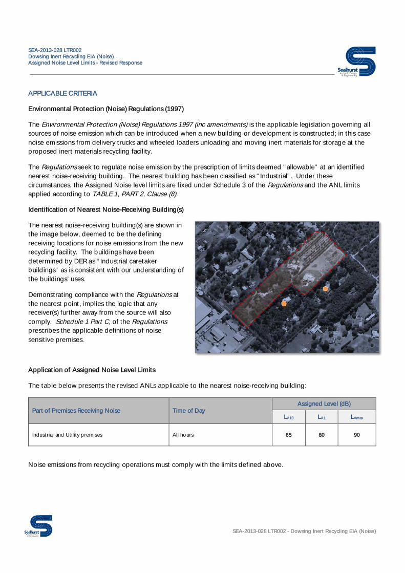
SEA-2013-028 LTR002Dowsing Inert Recycling EIA (Noise)Assigned Noise Level Limits - Revised Response
SEA-2013-028 LTR002 - Dowsing Inert Recycling EIA (Noise)
APPLICABLE CRITERIA
Environmental Protection (Noise) Regulations (1997)
The Environmental Protection (Noise) Regulations 1997 (inc amendments) is the applicable legislation governing allsources of noise emission which can be introduced when a new building or development is constructed; in this casenoise emissions from delivery trucks and wheeled loaders unloading and moving inert materials for storage at theproposed inert materials recycling facility.
The Regulations seek to regulate noise emission by the prescription of limits deemed "allowable" at an identifiednearest noise-receiving building. The nearest building has been classified as “Industrial”. Under thesecircumstances, the Assigned Noise level limits are fixed under Schedule 3 of the Regulations and the ANL limitsapplied according to TABLE 1, PART 2, Clause (8).
Identification of Nearest Noise-Receiving Building(s)
The nearest noise-receiving building(s) are shown inthe image below, deemed to be the definingreceiving locations for noise emissions from the newrecycling facility. The buildings have beendetermined by DER as “Industrial caretakerbuildings” as is consistent with our understanding ofthe buildings’ uses.
Demonstrating compliance with the Regulations atthe nearest point, implies the logic that anyreceiver(s) further away from the source will alsocomply. Schedule 1 Part C, of the Regulationsprescribes the applicable definitions of noisesensitive premises.
Application of Assigned Noise Level Limits
The table below presents the revised ANLs applicable to the nearest noise-receiving building:
Part of Premises Receiving Noise Time of DayAssigned Level (dB)
LA10 LA1 LAmax
Industrial and Utility premises All hours 65 80 90
Noise emissions from recycling operations must comply with the limits defined above.
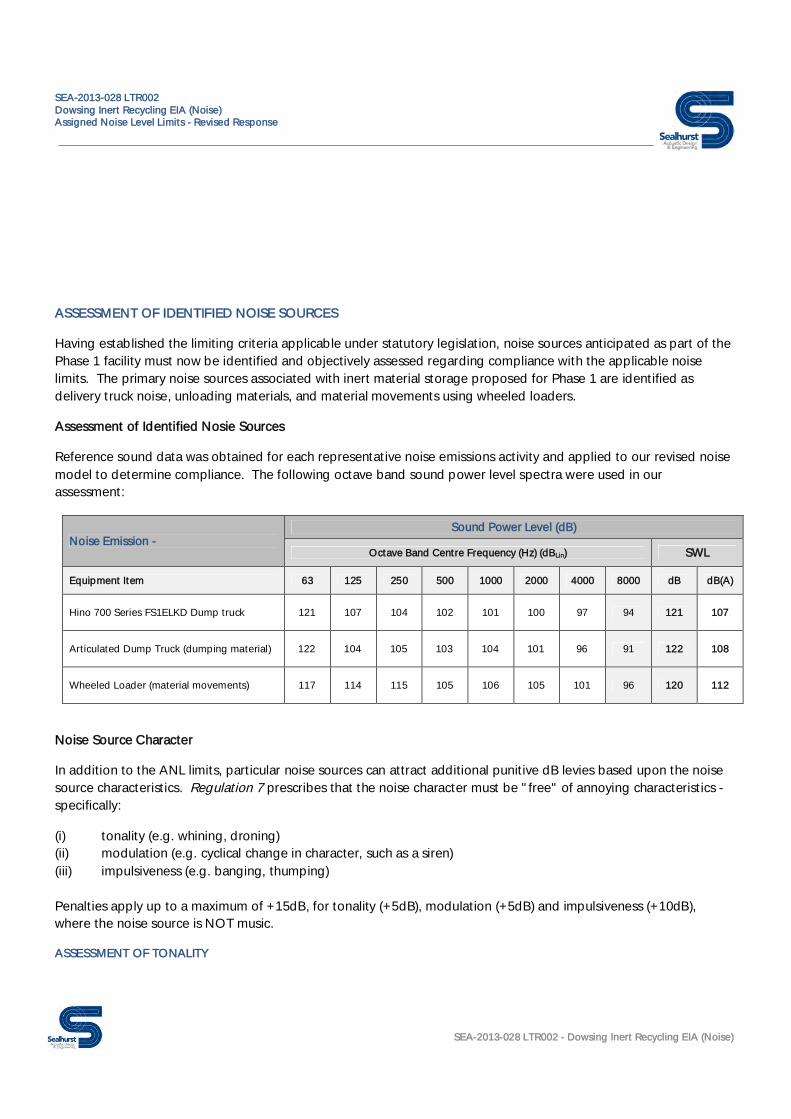
SEA-2013-028 LTR002Dowsing Inert Recycling EIA (Noise)Assigned Noise Level Limits - Revised Response
SEA-2013-028 LTR002 - Dowsing Inert Recycling EIA (Noise)
ASSESSMENT OF IDENTIFIED NOISE SOURCES
Having established the limiting criteria applicable under statutory legislation, noise sources anticipated as part of thePhase 1 facility must now be identified and objectively assessed regarding compliance with the applicable noiselimits. The primary noise sources associated with inert material storage proposed for Phase 1 are identified asdelivery truck noise, unloading materials, and material movements using wheeled loaders.
Assessment of Identified Nosie Sources
Reference sound data was obtained for each representative noise emissions activity and applied to our revised noisemodel to determine compliance. The following octave band sound power level spectra were used in ourassessment:
Noise Emission -Sound Power Level (dB)
Octave Band Centre Frequency (Hz) (dBLin) SWL
Equipment Item 63 125 250 500 1000 2000 4000 8000 dB dB(A)
Hino 700 Series FS1ELKD Dump truck 121 107 104 102 101 100 97 94 121 107
Articulated Dump Truck (dumping material) 122 104 105 103 104 101 96 91 122 108
Wheeled Loader (material movements) 117 114 115 105 106 105 101 96 120 112
Noise Source Character
In addition to the ANL limits, particular noise sources can attract additional punitive dB levies based upon the noisesource characteristics. Regulation 7 prescribes that the noise character must be "free" of annoying characteristics -specifically:
(i) tonality (e.g. whining, droning)(ii) modulation (e.g. cyclical change in character, such as a siren)(iii) impulsiveness (e.g. banging, thumping)
Penalties apply up to a maximum of +15dB, for tonality (+5dB), modulation (+5dB) and impulsiveness (+10dB),where the noise source is NOT music.
ASSESSMENT OF TONALITY

SEA-2013-028 LTR002Dowsing Inert Recycling EIA (Noise)Assigned Noise Level Limits - Revised Response
SEA-2013-028 LTR002 - Dowsing Inert Recycling EIA (Noise)
The subjective sound of unloading material and material movements is generally broadband, and can be likened toconstruction site-type noise emissions, which are not usually subject to additional penalties when assessingcompliance. However, where delivery trucks pass by nearest noise-receiving buildings, low frequency noise from thetruck engine at low speeds is likely to cause tonal noise to be received. Sealhurst have deemed it appropriate toattribute a tonal penalty of 5dB(A) to truck engine noise passing close to nearby noise receiving buildings. Noadditional penalties regards "unloading material of material movements have been applied.
TIMING AND FREQUENCY OF OPERATIONS
Consultation between TALIS, Sealhurst and DER has resulted in a 4 hour period of operations to be examined asrepresentative. In response, Dowsing have advised the following planned operations for site activity over a 4 hourperiod:
“It is proposed that in any four hour period there will be:
Two delivers of loads by Hino 700 Series FS1ELKD Tip Truck which should not take any more than 10 mins each
There will be 1 wheeled loader on site which will work for about 10 mins after each load and then some general sitemaintenance etc to be ~10 mins within a similar period. Therefore, it is anticipated that the loader will be operational for30 mins every 4 hours”
REFERENCE SITE PLAN
The Technical Appendices at the end of this report contains annotated site plans from which critical soundpropagation distances pertinent to noise emissions compliance were obtained. The following distances andexposure times are fundamental to our assessment:
· 12m – nearest point of passage of delivery trucks leaving the recycling plant site;
· 80m – minimum propagation distance to meet Assigned Noise Level limits from delivery truck noise,inclusive of -5dB(A) penalty;
· 58 seconds – time taken for single truck to pass nearest noise-receiving property to a zone whereby noiseemissions are predicted to be below the required limit at 5km/hr, inclusive of penalty;
· 29 seconds – time taken for single truck to pass nearest noise-receiving property to a zone whereby noiseemissions are predicted to be below the required limit at 10km/hr, inclusive of penalty;
ASSESSMENT
On the basis of the above and analysis of the site plan, (see Appendices) the following assessment was undertaken:
· Sound Power Level (SWL) data used to calculate corresponding sound pressure levels at nearest noise-receiving building in octave bands using inverse square propagation model;
· Resulting sound pressure levels compared to Assigned Noise Level (ANL) limits of LA10 65dB and LA1 80dBwith allowance for additional -5dB(A) tonal penalty;
· Where exceedence of the tonal penalty corrected LA10 60dB(A) is identified, exposure times were estimatedbased upon delivery truck speeds, whereby total exposure time for exceedence was compared against an“allowable” 24 minute period in any 4 hour period defined for LA10, or an “allowable” 2.4 minute period inany 4 hour period defined for LA1, beyond which exceedence would constitute a non-compliance;

SEA-2013-028 LTR002Dowsing Inert Recycling EIA (Noise)Assigned Noise Level Limits - Revised Response
SEA-2013-028 LTR002 - Dowsing Inert Recycling EIA (Noise)

SEA-2013-028 LTR002Dowsing Inert Recycling EIA (Noise)Assigned Noise Level Limits - Revised Response
SEA-2013-028 LTR002 - Dowsing Inert Recycling EIA (Noise)
COMPLIANCE STATEMENT
Sealhurst have prepared a cumulative calculation model based upon the information presented herein. Theresultant calculation model predicts that noise emissions from Dowsing Recycling’s proposed operations plan areable to meet the applicable Assigned Noise Level limits at the nearest noise-receiving building, provided the timingand measured distances are applied to the project during operations.
ADDITIONAL OPERATIONAL CONSIDERATIONS
TRUCK SPEED LIMIT
Noise emissions compliance and allowable periods of “exceedence” are based upon the advised truck speed of5km/hr. Estimated time taken for trucks to drive 160m through the “Exceedence Zone” at incremental speeds areas follows:
Truck SpeedTime Taken to pass throughExceedence Zone
Resultant Exceedence time per 4 hour period (2trucks)
5km/hr 116 seconds 3 minutes, 52 seconds
10km/hr 58 seconds 1 minute, 56 seconds
15km/hr 39 seconds 1 minute, 18 seconds
20km/hr 29 seconds 58 seconds
Provided safe operations can be maintained at higher speeds, e.g. 10km/hr, it would be possible for Dowsing toincrease their 4-hourly truck movement quota during busy periods and remain compliant with the Regulations basedupon ensuring the exceedence periods remain LESS THAN 24 minutes for the tonal penalty corrected 60dB LA10 ORLESS THAN 2.4 minutes. This is inclusive of wheeled loader movements, which are proposed to occur over 100maway, hence are not anticipated to be subject to timed exceedence limits.
TIMING OF DELIVERIES
As part of inert materials delivery management strategy, the time(s) of delivery should be managed to occurbetween the hours of 7am and 7pm, where practicable, to minimise potential disturbance.
DELIVERY TRUCK REVERSE BEEPERS
It is anticipated that delivery vehicles and wheeled loaders are required to produce safety warning signals whenreversing in industrial applications as a strategy to minimise human injury and increase vehicle movement safety,particularly in confined spaces. One common signal type is reverse beepers which, as an additional noise source canbe more likely to cause annoyance and potential complaint.
Regards reverse beepers, there exists a reasonable amount of literature[1], [2] demonstrating alternative safety devicesand management principles which can be employed to avoid this precise acoustical issue - as the issue is one ofsafety (with an acoustical annoyance outcome), by removing the reverse beeper alarm source in place of analternative (e.g. visual) alarm, the problem can be removed.

SEA-2013-028 LTR002Dowsing Inert Recycling EIA (Noise)Assigned Noise Level Limits - Revised Response
SEA-2013-028 LTR002 - Dowsing Inert Recycling EIA (Noise)
Such strategies are employed in existing high noise scenarios, where audio warnings have limited value - forexample high noise plant rooms, off shore installations etc where noise levels of warning sirens/signals may not beoverheard and/or could approach levels which would otherwise induce hearing damage in order to be heard.Typically staff in such areas may already be wearing ear defenders, therefore the principle is able to be implementedwhere certain constraints apply.
The one-way delivery route for trucks presented by Dowsing/TALIS shows reverse beepers will not be required bytrucks. Alternative safety strategy(s) for wheeled loader vehicles could be the application and use of reversingcameras, visual alarms signals (e.g. specific vehicle reverse lights) and safety management techniques such as the useof spotters, to be considered as part of the noise management strategy for the facility.
REFERENCED LITERATURE
[1] SAFE WORK AUSTRALIA - Draft guide Traffic Management: Construction Work;[2] ROADING NEW ZEALAND - Guideline for Controlling Reversing Vehicles DEC 2009;

SEA-2013-028 LTR002Dowsing Inert Recycling EIA (Noise)TECHNICAL APPENDICES
SEA-2013-028 LTR002 - Dowsing Inert Recycling EIA (Noise)
TECHNICAL APPENDICES
SITE LAYOUT MARK UP

&
&Monitor 2
Monitor 1
Proposed minor road (20m width)
Storage area
Storage area
One way
traffic
flow
Berkshire Rd
Walters W
y
Ashby Cl""
"
"
"" ""
" ""
"
"
""
""
"
"
"
MAHOGANYCREEK
PERTH
Document Path: \\server\Talis\SECTIONS\Waste\PROJECTS\TW2013\TW13009 - Dowsing Approvals\GIS\Maps\9. Dust & Noise\Figure 6 - Location of Noise Monitors.mxd
0 40Kilometres
X.XXXXXXXXX.XXXXXXXX XXXXXXXX.XXXXXXXX
6/02/2014 A000/00 A Rev A
LEGEND
Project No:
0 50 100 150 200 25025Meters
±Coordinate System: GDA 1994 MGA Zone 50
Projection: Transverse Mercator, Datum: GDA 1994, Units: Meter
Reviewed:
Prepared:Checked:Date:
Scale @ A3: 1:1,500 J BotterillN KingR M Cullen
TW13009
Figure 6
Site Boundary
kkkkkkkkkkkkkkkAccess RoadsCaretaker ResidenceNew Minor RoadArea to be clearedStorage AreaTraffic Flow
Setbacks10m minimum setback line (minor road)20m minimum setback for buildings6m minimum landscaping requirements
& Noise Monitors
RoadsHeirarchy
Access RoadDistributor ADistributor BLocal DistributorPrimary DistributorRegional Distributor
09/05/2013
LOCATION OF NOISE MONITORS DUST AND NOISE COMMISIONING MONITORING PLAN
Dowsing Concrete
Daryl Thompson
Oval
Daryl Thompson
Oval
Daryl Thompson
Oval
Daryl Thompson
Callout
80m "Exceedence" Zone Delivery trucks exiting the site will be able to comply with the Assigned Noise Level limits provided the noise emissions from trucks passing this area of adjoining property boundary does not exceed: - 65dB LA10 for 24 minutes in any 4 hour period, OR - 80dB LA1 for 2.4 minutes in any 4 hour period.
Daryl Thompson
Line
Daryl Thompson
Line
Daryl Thompson
Line
Daryl Thompson
Callout
80m
Daryl Thompson
Arrow
Daryl Thompson
Callout
80m
Daryl Thompson
Arrow
Daryl Thompson
Oval
Daryl Thompson
Callout
Nearest noise-receiving building

Dowsing Inert Recycling Facility
Acoustics - Noise Emissions Compliance of Inert Material Crushing Activity
A PHASE 1 – BASIS OF COMPLIANCE & PREVIOUS REPORTS
© SEALHURST PTY LTD All Rights Reserved SEA-2013-028 RPT001
A.3 SEA-2013-028 LTR003_Rev1

SEA-2013-028 LTR003_Rev1 - Dowsing Inert Recycling EIA (Noise)
Sealhurst Pty Ltd
PO Box 1082, BALCATTA, WA 6914
ABN: 86 161 563 551
ACN: 161 563 551
01 MAY 2014
Dowsing Inert Recycling EIA (Noise) – Revised Equipment & Operations Schedule
Dear Andrew,
In response to DER query regarding compliance with the Assigned Noise Levels at their inert recycling facility,
Sealhurst have prepared the following summary statement regarding operation period (T) and sound power level
(SWL) data contained within Dowsing’s proposed operations plan for their proposed inert recycling facility at
Berkshire Road, HIGH WYCOMBE WA.
The statement is provided to resolve potential compliance/noise emissions exceedence issues relating to wheeled
loader use, following DER queries regards specific equipment items and duration of use. Our advice is intended
to be supplementary to our previous detailed compliance advice letter, (Ref: SEA-2013-028 LTR002) whereby
compliance with the applicable limits were derived on an allowable emissions/operating time basis.
GENERAL APPRECIATION
Previous advice and assessment utilised sound power level data and timed noise emissions to demonstrate noise
emissions compliance for the delivery and storage of inert materials in preparation for recycling processing. An
operations plan was presented whereby compliance is based upon objective sound power levels over known
distances to neighbouring receiving properties, and the application of time-limited operation controls in order to
remain compliant; i.e. to remain within the allowable Assigned Noise Level limits (LA10, LA1, LAMAX) applicable to the
site.
We understand concerns were received relating to the level and duration of noise emission from specific wheeled
loader equipment initially proposed to move inert material to stockpiles following inert material delivery.
In order to demonstrate an alternative compliance strategy, Dowsing have provided a n inventory list of alternative
options to expedite inert material movement/storage which Sealhurst have reviewed in view of each equipment
item’s sound power level. Anticipated usage periods were also reviewed in order to determine a more efficient
(i.e. time limited) process for storage, in order to meet the required Assigned Noise Levels during operations
when assessed over a representative 4 hour period.
ALTERNATIVE SOUND POWER & TIMED EMISSIONS
Dowsing have a number of alternative vehicles and equipment able to complete the operations, as evidenced by
the inventory included in the Technical Appendices of this report.
The originally proposed wheeled loader is to be supplemented with an alternative skid steer type unit where inert
material movement operations are anticipated to take >24 minutes to remain compliant with the Assigned Noise
Level limits. The unit has significantly lower sound power level, and is able to complete specific lift/unload
operations in a shorter time period, thus reducing time spent manoeuvring inert material.
This amendment is to be included in Dowsing’s facility operations plan.
F.A.O Andrew Mack
Waste Management Section Leader
TALIS CONSULTANTS
Level 1, Unit 8 / 663 Newcastle Street
LEEDERVILLE
WA 6007

SEA-2013-028 LTR003_Rev1 - Dowsing Inert Recycling EIA (Noise)
Sealhurst Pty Ltd
PO Box 1082, BALCATTA, WA 6914
ABN: 86 161 563 551
ACN: 161 563 551
Sound power levels of the new 8T skid steer and the larger capacity Wheeled Loader unit are presented below:
Noise Emission -
Sound Power Level (dB)
Octave Band Centre Frequency (Hz) (dBLin) SWL
Equipment Item 63 125 250 500 1000 2000 4000 8000 dB dB(A)
Wheeled Loader (material movements) 117 114 115 105 106 105 101 96 120 112
Skid Steer 8t Loader (material movements) 100 91 95 95 91 90 84 78 103 97
TONALITY
We understand DER have deemed the emissions from inert material movements to be tonal when received at the
nearest receiver, implying an additional penalty of +5dB to noise emissions. Using the alternative skid steer
equipment sound power levels, we are able to calculate noise emissions to be <60dB(A) at distance above 29m,
which using the accepted calculation basis, provides the closest distance for emissions to occur before timed
emissions become part of the compliance strategy.
As a direct comparison, sound power emission predictions from the significantly larger capacity Wheeled Loader
unit calculated a level of 75dB(A) at an equivalent distance.
AMENDED OPERATIONS PLAN
Inert material movements (general) – Skid Steer;
Where noise/time-sensitive inert material movement operations occur:
Inert material movements greater than 24 minutes in any 4 hour period – Skid Steer;
Inert material movements less than 24 minutes in any 4 hour period – Wheeled Loader (if required);
On this basis we believe the proposed operations plan is now compliant with the Assigned Noise Level limits in
any 4 hour period.
Should further concerns infer an exceedence of the Assigned Noise level limits, all inert material movement
operation duration times would be limited to <24 minutes in any 4 hour period, in order to remain complaint.
If you have any queries, please feel free to contact me direct,
Kind Regards
Daryl Thompson
Director
Sealhurst Pty Ltd

SEA-2013-028 LTR003_Rev1
Dowsing Inert Recycling EIA (Noise)
TECHNICAL APPENDICES
SEA-2013-028 LTR003_Rev1 - Dowsing Inert Recycling EIA (Noise)
DOWSING EQUPMENT INVENTORY LIST
Bobcats, Excavators and Forklifts
2013 Toyota Skid Steer SDK8 Loader 1ECH792 SL15
2013 Toyota Skid Steer SDK8 Loader 1EHT456 SL16
2013 Toyota Skid Steer SDK8 Loader 1EFY219 SL17
2012 PT50 Series 3 Terex 1ECE626 SL14
2012 PT80 Series 3 Terex 1DZD909 SL13
2010 JCB Backhoe Wheel Loader 1DXU932 WL03
2010 SDLG LG936L Wheel Loader 1DJF283 WL01
2009 Cat Skid Steer 226B Loader 1DJF282 SL10
2007 Toyota Skid Steer SDK8 Loader 1DBG182 SL12
2006 Cat Skid Steer 226B Loader 1CJU839 SL07
2006 Takeuchi TB014 Mini Excavator 1CJA182 EX01
2005 Cat Skid Steer 950 Loader BY75453 WL02
2001 Komatsu FD 25T Forklift FL02

Dowsing Inert Recycling Facility
Acoustics - Noise Emissions Compliance of Inert Material Crushing Activity
B CALCULATION OF NOISE EMISSIONS LIMITS
© SEALHURST PTY LTD All Rights Reserved SEA-2013-028 RPT001
B. CALCULATION OF NOISE EMISSIONS LIMITS
An Assigned Noise Level is calculated for each noise sensitive receiver using a combination of environmental
factors local to the receiver. A standard set of ANL’s exist to provide a base level of acoustic amenity, as shown
in the Table below. These levels are modified by an Influencing Factor (IF) to reflect noise sensitivity in the
specific environment relative to the subject development.
To calculate the additional Influencing Factor (IF), concentric circles are drawn around the nearest noise-sensitive
reception point; one at 450m radius and one at 100m radius. Percentages are calculated for the amount of land
area within the circles used for noise emitting purposes (e.g. industrial or commercial uses) which are compared
to the total area encompassed by the concentric circles.
Traffic volume is taken into account in order to reach an acceptable ANL, or noise reception level, appropriate for
the area in which the receiver is to be situated.
Part of Premises Receiving Noise
Time of Day
Assigned Level (dB)
LA10 LA1 LAmax
Noise sensitive premises at locations within 15m of a building directly associated with a noise sensitive use
0700 to 1900 hours Monday to Saturday
45 + influencing factor
55 + influencing factor
65 + influencing factor
0900 to 1900 hours Sundays and public holidays
40 + influencing factor
50 + influencing factor
65 + influencing factor
1900 to 2200 hours all days
40 + influencing factor
50 + influencing factor
55 + influencing factor
2200 hours on any day to 0700 hours Monday to Saturday and 0900 hours Sunday and public holidays
35 + influencing factor
45 + influencing factor
55 + influencing factor
Noise sensitive premises at locations further than 15m of a building directly associated with a noise sensitive use
All hours 60 75 80
Commercial premises
All hours 60 75 80
Industrial and Utility premises
All hours 65 80 90

Dowsing Inert Recycling Facility
Acoustics - Noise Emissions Compliance of Inert Material Crushing Activity
C PROPOSED CRUSHING EQUIPMENT & OPERATIONS PLAN
© SEALHURST PTY LTD All Rights Reserved SEA-2013-028 RPT001
C. PROPOSED CRUSHING EQUIPMENT & OPERATIONS PLAN
C.1 Site Plan & Operations Layout

NOTES
1. This drawing is the property of Talis Consultants Pty Ltd. It is a confidential document and must not be copied, used, or its contents divulged without prior written consent.
2. All levels refer to Australian Height Datum.
3. DO NOT SCALE, use figured dimensions only, if in doubt please contact Talis Consultants.
No. Date App.Amendment / IssueDrw
n.Chk
.
Project: Title:Drawn by:
Checked by:
Approved by:
Scale:
Date:
Job No:
File No:
Drg. No: Rev:
Environmental Assessment
Management PlanSite Layout Plan
001 A
AU
RC
AM
1:1250
19/11/14
TE14019
TE14019DG001
8/663 Newcastle Street, Leederville WA 6007
PO Box 454, Leederville WA 6903
T: 1300 251 070
ASSET MANAGEMENT
ENVIRONMENTAL SERVICES
SPATIAL INTELLIGENCE
WASTE MANAGEMENT
w w w . t a l i s c o n s u l t a n t s . c o m . au
Client:
DC Recycling
A 21/11/14 KRIssue for ReportAU
KG
N
ACCEPTA
NCE
PROCESSIN
G
REC
YCLE
D P
RODUCT
OFFICE
WORKSHOP
CARPARK
WATER TANK
PUMP
ROAD RESERVE
ADDITIONAL PARKING
WEIGHBRIDGE
INSPECTION PLATFORM
GATE HOUSE
RECYCLING PLANT
EXCAVATOR
OUTGOING VEHICLES
INCOMING VEHICLES
SPRINKLER SYSTEM LINES
TRAFFIC FLOW LANES
SPRINKLER LOCATION
VALVE
GATE
FREE HOSE OUTLET
LEGEND

Dowsing Inert Recycling Facility
Acoustics - Noise Emissions Compliance of Inert Material Crushing Activity
C PROPOSED CRUSHING EQUIPMENT & OPERATIONS PLAN
© SEALHURST PTY LTD All Rights Reserved SEA-2013-028 RPT001
C.2 Ref: LPE301150 Dowsing Concrete Recyclers – Plant Setup #1
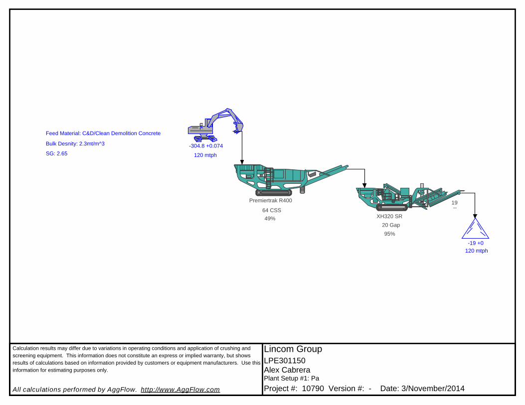
Calculation results may differ due to variations in operating conditions and application of crushing and
screening equipment. This information does not constitute an express or implied warranty, but shows
results of calculations based on information provided by customers or equipment manufacturers. Use this
information for estimating purposes only.
All calculations performed by AggFlow. http://www.AggFlow.com
Lincom Group
LPE301150Alex CabreraPlant Setup #1: Pa
Project #: 10790 Version #: - Date: 3/November/2014
120 mtph
-304.8 +0.074
Premiertrak R400
49%
64 CSSXH320 SR
120 mtph
-19 +0
95%
20 Gap
19--
Feed Material: C&D/Clean Demolition Concrete
Bulk Desnity: 2.3mt/m^3
SG: 2.65

Calculation results may differ due to variations in operating conditions and application of crushing and
screening equipment. This information does not constitute an express or implied warranty, but shows
results of calculations based on information provided by customers or equipment manufacturers. Use
this information for estimating purposes only.
All calculations performed by AggFlow. http://www.AggFlow.com
Lincom GroupLPE301150Alex CabreraPlant Setup #1: Page #1Project #: 10790 Version #: - Date: 3/November/2014
Feed GradingMaterial: C&D/Clean Demolition Concrete
Grading % Pass % Ret. TPH
304.8 100.0 0 0 203.2 98.0 2.0 2.4
152.4 92.0 6.0 7.2 101.6 80.0 12.0 14.4 76.2 73.0 7.0 8.4
50.8 62.0 11.0 13.2 38.1 57.0 5.0 6.0 25.4 48.0 9.0 10.8
19.05 45.0 3.0 3.6 12.7 41.0 4.0 4.8 9.53 37.0 4.0 4.8
6.35 34.0 3.0 3.6 4.76 30.0 4.0 4.8 2.38 24.0 6.0 7.2 2 21.0 3.0 3.6
1.19 19.0 2.0 2.4 0.595 14.0 5.0 6.0 0.297 10.0 4.0 4.8
0.149 4.0 6.0 7.2 0.074 0.0 4.0 4.8 Total - - 100.0 120 Grade
0
20
40
60
80
100
%

Calculation results may differ due to variations in operating conditions and application of crushing and
screening equipment. This information does not constitute an express or implied warranty, but shows
results of calculations based on information provided by customers or equipment manufacturers. Use
this information for estimating purposes only.
All calculations performed by AggFlow. http://www.AggFlow.com
Lincom GroupLPE301150Alex CabreraPlant Setup #1: Page #1Project #: 10790 Version #: - Date: 3/November/2014
-19mm Roadbase
Grading % Pass % Ret. TPH
19 100.0 0 0 14 95.2 4.8 5.8 10 87.0 8.1 9.7 6.3 78.2 8.8 10.6 5 73.8 4.5 5.4 2.36 52.3 21.4 25.7 1.18 38.5 13.8 16.6 0.6 27.0 11.5 13.7 0 0.0 27.0 32.4 Total - - 100.0 120
Grade
0
20
40
60
80
100
%
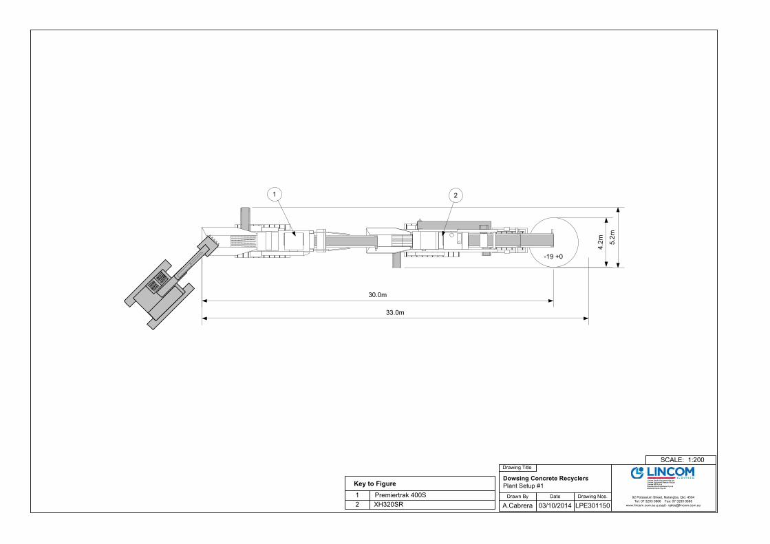
Drawn By Date
A.Cabrera 03/10/2014
Drawing Title
Dowsing Concrete Recyclers
Plant Setup #1
Drawing Nos.
LPE301150
1:200SCALE:
92 Potassium Street, Narangba, Qld. 4504
Tel: 07 3293 0888 Fax: 07 3293 0688
www.lincom.com.au e-mail:- [email protected]
Lincom Pacific Equipment Pty Ltd
Lincom Equipment Rentals Pty Ltd
Lincom NZ Pty Ltd
Powerscreen Australasia Pty Ltd
Morbark Pacific Pty Ltd
1 Premiertrak 400S
Key to Figure
2 XH320SR
-19 +0
1 2
30.0m
33.0m
5.2m
4.2m
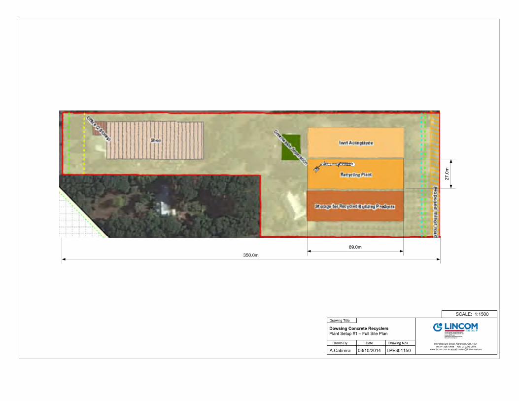
Drawn By Date
A.Cabrera 03/10/2014
Drawing Title
Dowsing Concrete Recyclers
Plant Setup #1 – Full Site Plan
Drawing Nos.
LPE301150
1:1500SCALE:
92 Potassium Street, Narangba, Qld. 4504
Tel: 07 3293 0888 Fax: 07 3293 0688 www.lincom.com.au e-mail:- [email protected]
Lincom Pacific Equipment Pty LtdLincom Equipment Rentals Pty Ltd
Lincom NZ Pty LtdPowerscreen Australasia Pty Ltd
Morbark Pacific Pty Ltd
350.0m
89.0m
27.0m

Drawn By Date
A.Cabrera 03/10/2014
Drawing Title
Dowsing Concrete Recyclers
Plant Setup #1 – Recycle Plant Plan
Drawing Nos.
LPE301150
1:400SCALE:
92 Potassium Street, Narangba, Qld. 4504
Tel: 07 3293 0888 Fax: 07 3293 0688
www.lincom.com.au e-mail:- [email protected]
Lincom Pacific Equipment Pty LtdLincom Equipment Rentals Pty Ltd
Lincom NZ Pty LtdPowerscreen Australasia Pty Ltd
Morbark Pacific Pty Ltd
1 Premiertrak 400S
Key to Figure
2 XH320SR
12
89.0m
27.0m

Dowsing Inert Recycling Facility
Acoustics - Noise Emissions Compliance of Inert Material Crushing Activity
C PROPOSED CRUSHING EQUIPMENT & OPERATIONS PLAN
© SEALHURST PTY LTD All Rights Reserved SEA-2013-028 RPT001
C.3 Proposed Plant Equipment
Powerscreen® XR400S
Jaw Crusher
SPECIFICATION - Rev 4. 01/08/2012

Powerscreen® XR400S
SPECIFICATION Rev 4. 01/08/2012
2
Features & Benefits The Powerscreen® X400S range of high performance primary jaw crushing plants are designed for medium scale operators in quarrying, demolition, recycling & mining applications. The range includes the XA400S with hydraulic adjust & the XR400S with hydraulic release. User benefits include track mobility for a quick set-up time, hydraulic crusher setting adjustment for total control of product size & crusher overload protection to prevent damage by un-crushable objects. � Output potential up to 400tph (440 US tph) � Hydraulic folding feed hopper with wedge fixing system � Heavy duty wear resistant feed hopper � Stepped self-cleaning grizzly feeder with under feeder screen option � Deep fines chute to reduce material blockages � Aggressive crushing action with high swing jaw encouraging material entry into crushing chamber � Hydraulic crusher overload, ideal for applications with un-crushable material in feed, up to 200mm3 � Hydraulic crusher setting adjustment � Improved manganese liner retention, protects jaw supports on both swing & fixed jaws � Excellent under crusher access for removal of wire with hydraulic raise lower product conveyor � Angle adjustable product conveyor, 3.9m discharge height, lowers for transport � Low fuel consumption due to highly efficient direct drive system � Easy access powerunit canopy � PLC control system with auto start facility � Remote control via umbilical � Dust suppression system � Easily set up
Applications
Aggregate Recycling Mining
� Sand & gravel � C&D waste � Processed ores
� Blasted rock � Overburden � Processed minerals
� River rock � Foundry waste
Specification XR400S
Total weight 44,750kg (98,656lbs) including magnet & dirt conveyor
Transport Length 15.2m (49’ 10”)
Width 2.8m (9’ 2”), 4.3m (14’ 1”) including dirt conveyor
Height 3.4m (11’ 2”)
Working Length 14.9m (49’ 10”)
Width 4.3m (14’ 1”) with dirt conveyor
Height 4.1m (13’ 6”)
Crusher type: Single toggle jaw, feed opening 1100mm x 700mm (44”x28”)
Paint colour: RAL 5021
Powerunit: Caterpillar C9 ACERT 194kW (260hp) or Scania DC9 070A 202kW (275hp)

Powerscreen® XR400S
SPECIFICATION Rev 4. 01/08/2012
3
Jaw Crusher Crusher type: Single toggle jaw with hydraulic setting adjustment Feed opening: 1100mm x 700mm (44” x 28”) Bearings: Self aligning spherical roller Lubrication: Grease Drive: Wedge belts with screw tension
adjustment on engine Pre-set: 75mm (3”) closed side setting (CSS) Minimum setting: 50mm (2”) CSS recycling 75 mm (3”) CSS quarry All settings measured from root to tip
& subject to suitability of feed material. This plant is designed for recycling applications but can be used on quarry applications where appropriate. If in doubt please contact your dealer or Powerscreen.
Maximum setting: 125mm (5”) CSS Hydraulic adjustment: Fitted as standard Hydraulic overload: System designed to prevent damage
caused by tramp metal up to 200mm (8”) lump size (maximum edge length) Any downstream plant must be capable of accepting oversize from dumped condition
Controls: When overload occurs, feeder will
stop, crusher & product conveyor will continue to operate until re-set
Chamber Features � Quick & easy setting adjustment � Drawback rod adjustments not required during
setting changes � Jawstock supported on both sides, even stress
distribution � Strong frame construction, no welding in critical
areas � Cylinders mounted in line with side plates � Cartridge type bearings � Overlap jaw protects tip of jawstock/pitman � One piece fixed jaw support � Proven manganese liner retention
Shims Toggle beam
Toggle Hydraulic cylinders

Powerscreen® XR400S
SPECIFICATION Rev 4. 01/08/2012
4
Product Conveyor Dirt/Conveyor
Blanking mat or underscreen
Grizzly
Hopper Hopper type: Boltless hydraulic folding hopper,
over centre struts & wedge lock Hopper length: 4.9m (16’ 1”) Hopper width: 2.4m (7’ 11”) Hopper capacity: 10m 3 (13 cu. yd.) Hopper body: 15mm thick wear resistant steel
plate, mild steel reinforcing ribs Control: Variable speed control through a
proportional flow control valve
Vibrating Grizzly Feeder Type: Spring mounted vibrating pan &
grizzly feeder Vibrating Unit: Twin heavy-duty cast eccentric
shafts running in spherical roller bearings, gear coupled at drive end
Drive: Flange mounted hydraulic motor Feeder length: 4.08m (13’ 5”) Feeder width: 1.06m (3’ 6”) Grizzly: 2 replaceable 1.60m long stepped
cartridge type grizzlies 50mm nominal aperture, self cleaning
Grizzly length: 2.12m (7’) Under-screen: Rubber blanking mat fitted as stand-
ard. Can be substituted for optional wire meshes, use in conjunction with optional side conveyor.
Plant Chute-work
Crusher feed chute: One piece fabrication with 12mm thick mild steel plate sides with 20mm thick bottom plate
Grizzly fines/ bypass 2-way dirt chute provided to chute: discharge to product conveyor or
optional dirt conveyor when fitted. Fabricated from 6mm mild steel,
complete with hand operated flap door to direct grizzly fines to either dirt conveyor or product conveyor.

Powerscreen® XR400S
SPECIFICATION Rev 4. 01/08/2012
5
Product Conveyor Conveyor type: Troughed belt conveyor Design: Hydraulic raise & lower facility to aid
rebar removal & transportation. Can be raised or lowered whilst crushing. Fully removable modular unit to aid access & maintenance.
Belt type: EP630/4 with 6mm top & 2mm
bottom cover, vulcanised Belt width: 1000mm (39”) Discharge height: 3.9m (12’ 9”) Stockpile volume: 89m 3 (116 cu. yd.) Max. clearance: 472mm (jaw to belt - lowered) 747mm (engine to belt - lowered) Drive: Direct drive hydraulic motor Tunnel: Conveyor fitted with tunnel & side
covers to minimise rebar snagging Feedboot: Mild steel plate with abrasion
resistant steel liners at feed point Belt adjustment: Screw adjusters at head drum Belt covers: Canvas type removable dust covers
fitted to head section beyond magnet Belt scraper: Polyurethane blades as standard Lubrication: Remote head drum grease points
located under shedder plate Skirting: Wear resistant rubber skirts along
entire conveyor length
Dust Suppression System Sprays bars with atomiser nozzles mounted over crusher mouth, product conveyor feed & discharge points. Piped to an inlet manifold for client’s pressured water supply. Type: Clean water multi atomising nozzles Inlet: Single filtered inlet point on chassis Pressure: 2.8 bar (42 psi) Frost protection: Via system drain valves Pump: Optional extra
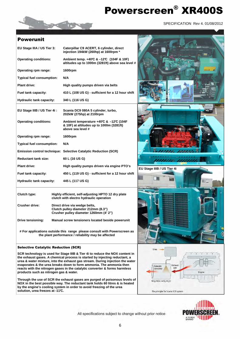
Powerscreen® XR400S
SPECIFICATION Rev 4. 01/08/2012
6
Selective Catalytic Reduction (SCR)
SCR technology is used for Stage IIIB & Tier 4i to reduce the NOX content in the exhaust gases. A chemical process is started by injecting reductant, a urea & water mixture, into the exhaust gas stream. During injection the water evaporates & the urea breaks down to form ammonia. The ammonia then reacts with the nitrogen gases in the catalytic converter & forms harmless products such as nitrogen gas & water. Through the use of SCR the exhaust gases are purged of poisonous levels of NOX in the best possible way. The reductant tank holds 60 litres & is heated by the engine’s cooling system in order to avoid freezing of the urea solution, urea freezes at -11°C.
Powerunit EU Stage IIIA / US Tier 3: Caterpillar C9 ACERT, 6 cylinder, direct injection 194kW (260hp) at 1600rpm * Operating conditions: Ambient temp. +40°C & –12°C (104F & 10F) altitudes up to 1000m (3281ft) above sea level # Operating rpm range: 1600rpm Typical fuel consumption: N/A Plant drive: High quality pumps driven via belts Fuel tank capacity: 410 L (108 US G) - sufficient for a 12 hour shift Hydraulic tank capacity: 340 L (116 US G)
EU Stage IIIB / US Tier 4i : Scania DC9 080A 5 cylinder, turbo, 202kW (275hp) at 2100rpm Operating conditions: Ambient temperature +40°C & –12°C (104F & 10F) at altitudes up to 1000m (3281ft) above sea level # Operating rpm range: 1600rpm Typical fuel consumption: N/A Emission control technique: Selective Catalytic Reduction (SCR) Reductant tank size: 60 L (16 US G) Plant drive: High quality pumps driven via engine PTO’s Fuel tank capacity: 450 L (119 US G) - sufficient for a 12 hour shift Hydraulic tank capacity: 445 L (117 US G)
Clutch type: Highly efficient, self-adjusting HPTO 12 dry plate clutch with electro hydraulic operation Crusher drive: Direct drive via wedge belts, Clutch pulley diameter 212mm (8.3”) Crusher pulley diameter 1260mm (4’ 2”) Drive tensioning: Manual screw tensioners located beside powerunit
# For applications outside this range please consult with Powerscreen as the plant performance / reliability may be affected
EU Stage IIIB / US Tier 4i

Powerscreen® XR400S
SPECIFICATION Rev 4. 01/08/2012
7
Crawler Tracks Type: Heavy-duty tracks Pitch: 190mm Longitudinal centers: 3715mm Track width: 500 mm Climbing grade: 25˚ maximum Speed: 0.9kph (0.56mph) Drive: Hydraulic motors Tensioning: Hydraulic adjuster, grease tension
Platforms A detachable access ladder is provided to gain access to each side of the powerunit
A maintenance platform is provided on one side of the feeder with double row handrails & access ladders. A platform is also included to gain access between the crusher & the powerunit.
Guarding Wire mesh or sheet metal guards are provided for all drives, flywheels, pulleys & couplings The guards provided are designed & manufactured to meet CE & ANSI standards Hinged access guards are provided on the top, side & both ends of the engine
EU Stage IIIA / US Tier 3 only
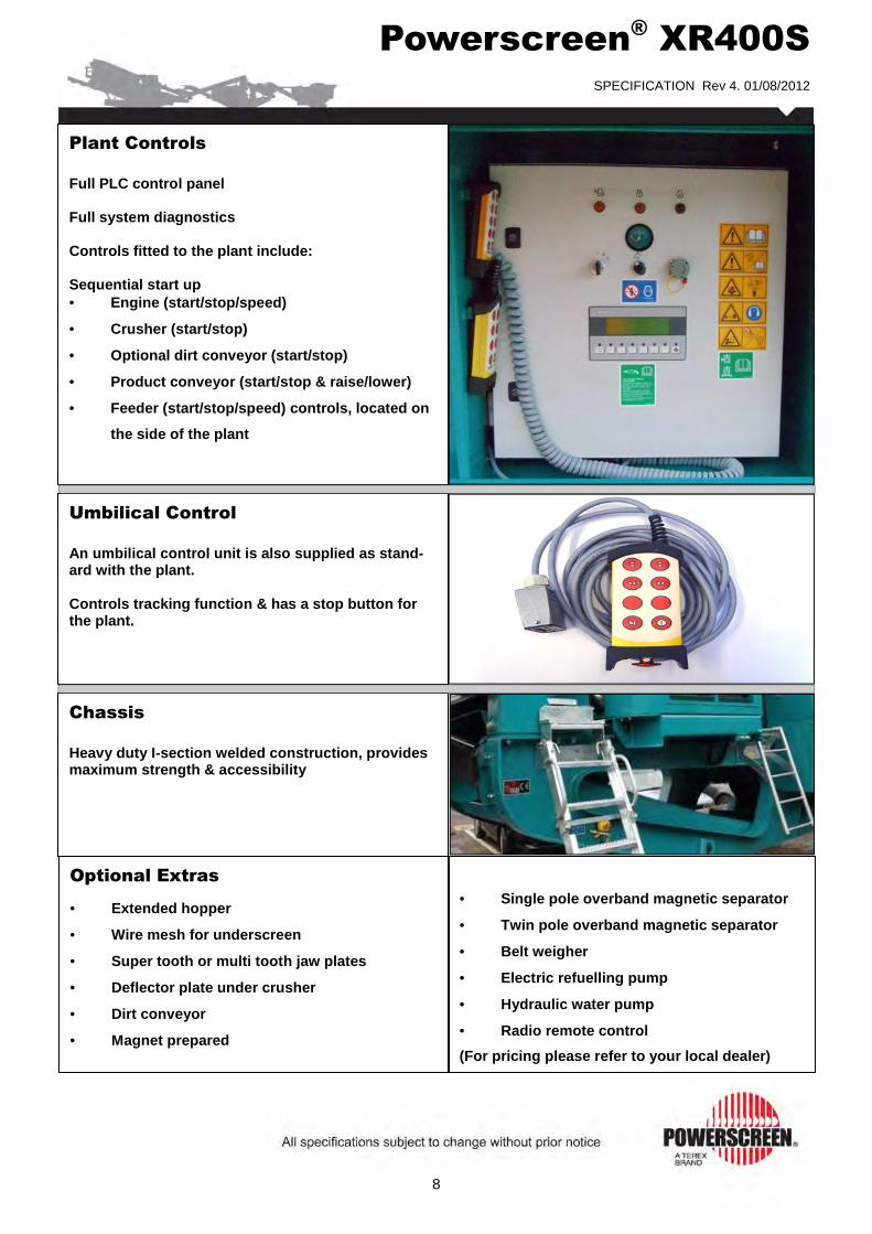
Powerscreen® XR400S
SPECIFICATION Rev 4. 01/08/2012
8
Chassis
Heavy duty I-section welded construction, provides maximum strength & accessibility
Plant Controls
Full PLC control panel Full system diagnostics Controls fitted to the plant include: Sequential start up • Engine (start/stop/speed)
• Crusher (start/stop)
• Optional dirt conveyor (start/stop)
• Product conveyor (start/stop & raise/lower)
• Feeder (start/stop/speed) controls, located on
the side of the plant
Umbilical Control
An umbilical control unit is also supplied as stand-ard with the plant. Controls tracking function & has a stop button for the plant.
Optional Extras
• Extended hopper
• Wire mesh for underscreen
• Super tooth or multi tooth jaw plates
• Deflector plate under crusher
• Dirt conveyor
• Magnet prepared
• Single pole overband magnetic separator
• Twin pole overband magnetic separator
• Belt weigher
• Electric refuelling pump
• Hydraulic water pump
• Radio remote control
(For pricing please refer to your local dealer)

Powerscreen® XR400S Options
SPECIFICATION - Rev 4. 01/08/2012
9
Jaw Profiles A choice of jaw profiles are available to maximise perfor-mance across all applications. All jaw profiles supplied in 18% Manganese as standard. This is the proven material for quarry & recycling applications with an initial hardness of around 230BHN (Brinell Hardness). Premium Jaws (Standard offering)
Premium jaws are fitted as standard in all XR400 jaw crushers. They are suitable for most quarry & recycling applications & give an excellent cost per tonne crusher. Super Tooth Jaws
For extended life across most quarrying applications. Super tooth has a significantly increased wear life using a deeper profile without comprising strength or product shape. Multi Tooth Jaws
The industry choice for many recycling applications. The “sharper” profile makes the Multi tooth ideal for most recycling applications, particularly those involving con-crete. It is also more tolerant when recycling asphalt. Wear life will be reduced on abrasive applications.
Under Crusher Deflector Plate A hydraulic adjustable deflector plate, increases belt protection on recycling applications. Situated immediately below the crusher outlet point & is fitted with a 15mm thick wear resistant plate. Deflector plate working angle can be adjusted from the PLC control system.
Feeder Under Screen Mesh Position: Removable wire meshes fitted in lieu of the standard rubber blanking mat, use in conjunction with optional dirt conveyor Width: 1075mm (3’ 6”) Length: 1250mm (4’ 1”)
Hopper Extensions Hopper type: Hydraulic folding extended hopper with over centre struts & wedge-lock system Hopper length: 4915mm (16’ 1”) Hopper width: 3815mm (12’ 6”) Hopper body: 15mm wear resistant plate, steel ribs

Powerscreen® XR400S Options
SPECIFICATION - Rev 4. 01/08/2012
10
Magnet Options: Magnet prepared Terex TX440 single pole (S.P.) Terex TX440X twin pole (T.P.) Belt width: 750mm (30”) Centres: 1700mm (67”) Drive / Control: Direct drive hydraulic motor,
pre-set variable speed Discharge: LHS via stainless shedder plate Weight: S.P. 975kg (2150lbs) T.P. 1470kg (3240lbs)
Dirt Conveyor Conveyor type: Troughed belt conveyor, folds
hydraulically for transport Width: 600mm (23.6”) Discharge height: 2.0m (6’5”) Stockpile volume: 12m 3 (16 cu. yd.) Drive: Direct drive hydraulic motor Position: Discharge on RHS of plant
Radio Remote Control Complete with integrated tracking functions & plant stop button. NB - Only available in certain countries where type approval has been obtained. Remote can also be used to: � Feeder (start/stop)
Belt Weigher Type: Modular scale with stainless load cells, single idler speed wheel & display unit Accuracy: + 1.0 + 0.5% Load cells: 2 temperature compensated parallelogram-style, stainless steel Display: Separate read out near control panel
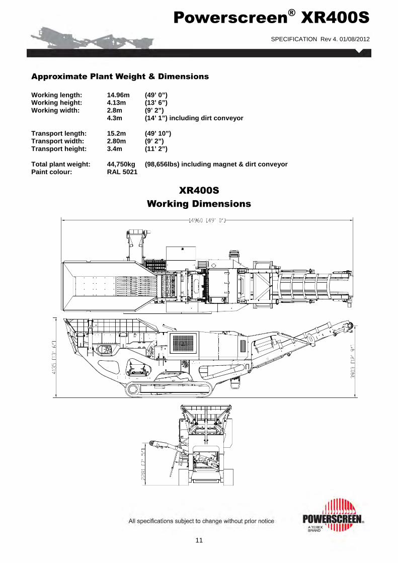
Powerscreen® XR400S
SPECIFICATION Rev 4. 01/08/2012
11
Approximate Plant Weight & Dimensions
Working length: 14.96m (49’ 0”) Working height: 4.13m (13’ 6”) Working width: 2.8m (9’ 2”) 4.3m (14’ 1”) including dirt conveyor Transport length: 15.2m (49’ 10”) Transport width: 2.80m (9’ 2”) Transport height: 3.4m (11’ 2”) Total plant weight: 44,750kg (98,656lbs) including magnet & dirt conveyor Paint colour: RAL 5021
XR400S
Working Dimensions

Powerscreen® XR400S
SPECIFICATION Rev 4. 01/08/2012
12
Terex GB Ltd. 200 Coalisland Road
Dungannon Co. Tyrone
Northern Ireland BT71 4DR
Tel: +44(0) 28 8774 0701 Fax: +44(0) 28 8774 6569
E-Mail: [email protected]
Web: www.powerscreen.com
Terex is a registered trademark of Terex Corporation in the United States of America and many other countries. Powerscreen is a registered trademark of Terex GB Ltd in the United States of America and many other countries. Copyright Terex Corporation 20112
Powerscreen equipment complies with CE requirements. Please consult Powerscreen if you have any other specific requirements in respect of guarding, noise or vibration levels, dust emissions, or any other factors relevant to health and safety measures or environmental protection needs. On receipt of specific requests, we will endeavour to ascertain the need for additional equipment and, if appropriate, quote extra to contract prices. All reasonable steps have been taken to ensure the accuracy of this publication, however due to a policy of continual product devel-opment we reserve the right to change specifications without notice. It is the importers’ responsibility to check that all equipment supplied complies with local legislation regulatory requirements. Plant performance figures given in this brochure are for illustration purposes only and will vary depending upon various factors, including feed material gradings and characteristics. Information relating to capacity or performance contained within this publication is not intended to be, nor will be, legally binding.

Powerscreen® XH320X Horizontal Impactor
SPECIFICATION - Rev 0. 01-06-2012

Powerscreen® XH320X
SPECIFICATION - Rev 0. 01-06-2012
2
Features & Benefits The Powerscreen ® XH320X Horizontal Shaft Impactor is a highly compact tracked crusher designed to offers both excellent reduction & high consistency of product yield. The Powerscreen ® XH320X is designed to give optimum performance in both quarry & recycling applica-tions & is an ideal mid size contractors machine due to it’s compact design & mobility. � Output potential up to 320 tph (353 US tph) � Double deck grizzly feeder with under screen � Load management system to control feeder speed � Suitable for a variety of feed materials � Proven Terex Impact Crusher with hydraulic overload protection, 4 bar rotor & twin apron design � Crusher speed variation through user friendly PLC control system � Fully independent under crusher vibrating pan feeder � Modular conveyor with raise/lower facility to aid clearance of rebar � Powerful overband magnet (optional) � Designed to give optimum performance in both quarry, demolition & mining applications � Latest generation powerunits that meet EU Stage IIIB / US Tier 4i & EU Stage IIIA / US Tier 3
emissions legislation � Hydraulically operated clutch & highly fuel efficient direct drive system � SR X configuration optional with 2 deck 3.3m x 1.5m (11’ x 5’) post screen with detachable 2 deck
post screen and fines conveyor
Application
Specification XH320X
Total weight 36,540kg (80,469lbs)*
Transport Length 14.4m (47’ 3”) *
Width 2.55m (8’ 5”) *
Height 3.4m (11’ 2”) *
Working Length 16.15m (53’ 0”) *
Width 8.60m (28’ 3”) with side conveyor deployed
Height 4.56m (15’ 0”)
Crusher type: Twin apron 4 bar impact crusher, feed opening 1130 x 800mm (44.5” x 31.5”)
Paint colour: RAL 5021
Powerunit: Caterpillar C9 ACERT 242 kW (325hp) or Scania DC9 070A 257 kW (350hp)
* = c/w Tier 4 Engine with Pan Feeder & Pre-screen, Hopper, Dirt and Product Conveyor extensions, Magnet
Aggregate Recycling Mining
� Blasted rock � C & D waste � Processed ores � River rock � Foundry waste � Processed minerals

Powerscreen® XH320X
SPECIFICATION - Rev 0. 01-06-2012
3
Principal components of the Powerscreen® XH320X Impact Crusher
Crusher Opening
Rubber Curtain
Chain Curtain
Inlet Chute
Inlet Wear Beam
Full Blowbar
Half Blowbar
Principles of Operation
Material enters via crusher opening & slides down the inlet chute where it is struck by the blowbars fixed within the rotor. This initial impact breaks the material which is then accelerated towards the top apron where more reduction takes place on impact. This material then falls back onto the blowbars & the cycle is repeated until the material is small enough to pass between the top apron & blowbar. Further reduction occurs on the bottom apron until the material can again pass through the gap & discharge from the underside of the crusher. Should an un-crushable object enter the chamber, the overload cylinders will relieve & allow the object to pass. The cylinders will then return to the pre-set crushing position. The pre-set gap is adjusted by turning the adjustment spindle whilst the weight of the apron is held on the cylinder (hydraulic assist).
Crusher Specification
• Feed opening: 1130mm x 800mm (44.5” x 31.5”) • Maximum piece size* 450mm 3 (18in 3 ) / 780mm (31”) diagonally / 800x500x250mm (31x20x10”) slab • * depending on material & blowbar spec • Rotor width: 1100mm (43.3”) • Rotor diameter: 1040mm (41”) • Number of aprons: 2 • Maximum Clearance: 180mm (7”) on both aprons • Maximum OSS setting: 150mm (6”) upper apron, 75mm (3”) lower apron • Minimum CSS setting: 50mm (2.4”) upper apron, 20mm (0.75”) lower apron • Number of blowbars: 4 • Blowbar removal: Vertically • Blowbar configuration: 2 full & 2 half (Optional 4 full) • Setting adjustment: Hydraulic assist • Overload protection: Hydraulic • Rotor speeds: 606 - 740rpm (33 - 42 m/s) (108 - 137 ft/s) • Applications: Demolition/Recycling/Quarry • Crusher weight: 8500kg (18,740lbs) • Full Blowbar weight: 220kg (485lbs) • Side liners: 20mm (0.75”) thick, abrasive resistant steel
Apron Adjustment Spindle Control Cylinder Top Impact Apron Apron Adjustment Spindle Bottom Impact Apron Control Cylinder Wear Liners Rotor
The hydraulic cylinders are pre-loaded to minimise apron bounce & wear on the cylinders. This arrangement also greatly reduces the oversize produced & is Patent Pending GB2455203

Powerscreen® XH320X
SPECIFICATION - Rev 0. 01-06-2012
4
Main Features
Crusher body: Precision Fabricated from structural steel plate & fully lined with replaceable 500 HB abrasion resistant liner plates. Hinged side door allows access to apron tips & rotor for gap measurements & inspection. Complete hinged section opens hydraulically to allow blowbar removal & replacement, apron & liner replacement or major maintenance
Rotor: Structural steel & fitted with four reversible, replaceable & fully clamped blowbars
Bearings: Double row self aligning spherical roller bearing fitted each end of rotor
Aprons: Cast manganese steel with replaceable 500 HB abrasion resistant wear plate on tip of bottom apron
Drive: Direct through wedge belts with tensioning system on powerunit
Lubrication: Grease lubricated rotor bearings fitted with inner & outer independently lubricated heavy duty labyrinth seals
Blowbars: Martensitic steel come as standard, High chrome & Ceramic Blowbars optional
This plant is designed for both demolition & quarryi ng applications. When fitted with Martensitic or Ceramic Blowbars the crusher will tolerate small quantities of steel reinforcing bar in the feed. However, the machine is not designed to accept large pieces of steel or other un-crushable objects, & the feed material should be assessed / inspected for suitability prior to crushing. It is vitally important that large pieces of steel or similar un-crushable objects are not allowed to enter the crushing chamber as severe damage & injury may occur. When high chrome bars are fitted all steel should be removed from the feed material. The machine should only be used on quarry applications or clean materials such as asphalt.
Powerscreen® XH320X - Impact Crusher
Chain Curtain Cover Main Welded Body Impactor Hinged Section Toggle Bolts with Enclosed Polyurethane Shock Absorber Inspection Covers Hydraulic Overload & Adjustment Cylinders Side Door Inspection Covers Bearing Plumber Block Housing with Mud Guard and Heavy Duty Labrynth Seals Trunions Hinged Section Opening Cylinders

Powerscreen® XH320X
SPECIFICATION - Rev 0. 01-06-2012
5
Blowbar Jib Crane Part No. CR014-054-601
Fixes to pre-existing allocated mounting points on chamber
fixed body- Kit provides all necessary parts with no
rework required
Pivot and track facilitates full access to blowbar and swings clear of body during operation
with minimal footprint
500 kg s.w.l. pulley block
Designed to work with chamber blowbar cradle
Available Options for Powerscreen® XH320X - Impact Crusher
Grinding Path Part No. CR014-193-601 Lubricated split pivot blocks for ease of maintenance Self retained manganese steel grinding rails with AR steel top plate Lubricated adjusting spindle with provision to fit socket for ease of adjustment Kit provides all necessary parts to retrofit to existing feedboot with no rework required

Powerscreen® XH320X
SPECIFICATION - Rev 0. 01-06-2012
6
Hopper Low profile hopper as standard, rigid hopper sides, no setup required, mounted directly to chassis. Hopper length: 4.04 m (13’ 3”) Hopper width: 2.1 m (83”) Hopper capacity: 3.6m 3 (4.7 cu. yd.) level Hopper body: 8mm (0.31”) thick abrasion resistant steel plate
Grizzly Feeder Vibrating grizzly feeder pan with efficient, self cleaning integral two stage grizzly section. Type: Fully sprung vibrating pan Length: 3.87m (12’ 8”) Width: 1080mm (42.5”) Pan: 10mm (0.4”) thick abrasion resistant base plate Drive unit: Twin heavy duty cast eccentric shafts, running in spherical roller bearings, gear coupled at drive end Drive: Flange mounted hydraulic motor Grizzly: Two stepped bolt in cartridge sections with 950mm (37.4”) long self cleaning fingers set at 42mm (1.65”) nominal spacing. Optional Grizzly cartridges 30mm & 60mm, Optional Punch Plate Cartridges 30mm, 45mm & 60mm. Screen: Removable rubber blanking mat fitted as standard, mesh screens optional Control: Variable speed control via control panel & on optional radio remote where specified Chute: Plant features bypass chute with internal two way flap door that controls the direction of fines, either forward onto product belt or down onto optional side conveyor where specified

Powerscreen® XH320X
SPECIFICATION - Rev 0. 01-06-2012
7
Product Conveyor Common features: Conveyor is shallow troughed with rollers at the lower end & a stainless steel tray
design below magnet discharge area, fully tunnelled with minimal snag areas
Belt specification: EP630/4 with 6mm top & 2mm bottom heavy duty rubber covers, vulcanised joint
Belt width: 1000mm (40”)
Feedboot: Fabricated steel with abrasion resistant steel liners
Impact area: Low friction impact bars (Under crusher pan feeder optional)
Skirting: Fully skirted in wear resistant rubber up to magnet discharge area
Drive: Hydraulic motor direct to head drum
Lubrication: Centralised greasing bank, for shaft bearing lubrication
Dust covers: Aluminium removable dust covers are fitted over the exposed section of the
conveyor. Optional head drum hood available
Belt adjustment: Belt tensioning using screw adjusters at head drum
Pressure sensor: Designed to stop plant feed if the discharge conveyor slows or stops
Product Conveyor Standard Configuration
Conveyor features: Fully removable modular unit
Hydraulic raise & lower facility to increase clearance & aid rebar removal
Hydraulic raise & lower facility can be operated whilst crushing
Discharge height: 3.45m (11’ 4”) in fully raised position Stockpile volume: 61m 3 (80 cu. yd.) Discharge height: 4.0m (13’ 2”) in fully raised position (extended conveyor) Stockpile volume: 61m 3 (80 cu. yd.)
Product Conveyor SR X Configuration
Conveyor features: Fully removable modular unit
Manual hydraulic raise & lower facility

Powerscreen® XH320X
SPECIFICATION - Rev 0. 01-06-2012
8
Vibrating Pan Feeder Type: Steel bodied vibrating feeder fitted with abrasion resistant liners, mounted under the crusher & designed to prevent any impact damage to the product conveyor belt Width: 990mm (39”) Length: 2.44m (8’) Drive: Hydraulic, out of balance exciter unit Speed: 1150 - 1200rpm fixed
Full Length Product Conveyor
Product Conveyor & Pan Feeder Interface

Powerscreen® XH320X
SPECIFICATION - Rev 0. 01-06-2012
9
Crawler Tracks Type: Heavy duty, 2 speed, bolt on Track centres: XH320: 3300mm (10’ 10”) XH320SR: 3840mm (12’ 7”) Shoe width : 400mm (16”) Gradient: 30˚maximum High speed : 1.0kph (0.62 mph) Low speed : 0.3kph (0.2 mph) Drive : Hydraulic Tensioning: Hydraulic adjuster, grease tensioned
Guarding Wire mesh or sheet metal guards are provided on all drives, flywheels, pulleys & couplings The guards provided are designed & manufactured to CE & ANSI standards
Platforms Platforms are provided for maintenance on one side of the feeder & Impactor. These are fitted with double row handrails & access ladders Platforms are also provided to gain access to the rear of the crusher & the powerunit Galvanised walkways as standard
Dust Suppression System Spray bars with atomiser nozzles are mounted over the product conveyor feed & discharge points, piped to an inlet manifold for customer water supply or optional pump Type: Clean water multi atomising nozzles Inlet: Single point Inlet pressure: 3 Bar (44 psi) Water supply: 24 L/min (6.34 G/min) minimum Frost protection: Via system main valves Pump: Optional

Powerscreen® XH320X
SPECIFICATION - Rev 0. 01-06-2012
10
Selective Catalytic Reduction (SCR) SCR technology is used for Stage IIIB & Tier 4i to reduce the NOX content in the exhaust gases. A chemical process is started by injecting reductant, a urea & wa-ter mixture, into the exhaust gas stream. During injection the water evaporates & the urea breaks down to form ammonia. The ammonia then reacts with the nitrogen gases in the catalytic converter & forms harmless products such as nitrogen gas & water. Through the use of SCR the exhaust gases are purged of poisonous levels of NOX in the best possible way. The Reductant tank holds 60 litres & is heated by the engine’s cooling system in order to avoid freezing of the urea solution, urea freezes at -11°C.
Powerunit EU Stage IIIA / US Tier 3: Caterpillar C9 ACERT , 6 cylinder, direct injection 242 kW (325hp) at 2000rpm * Operating Conditions: Ambient temp. +40°C & –12°C (104ºF & 10ºF) altitudes up to 1000m (3281ft) above sea level. # Operating rpm range: 1700 - 2100rpm Typical fuel consumption: 38 L/hr (10 G/hr) Up to 6.5 tonnes tons of crushed product per litre of fuel consumed (25 tons/G) Plant drive: High quality pumps driven via belts from engine Fuel tank capacity: 500L (132 US G) - Sufficient to run a 12 hour shift
EU Stage IIIB / US Tier 4i : Scania DC09 083A 5 cylinder, turbo, 257 kW (350hp) at 2100rpm, Operating Conditions: Ambient temp.+40°C & –12°C (104ºF & 10ºF) at altitudes up to 1000m (3281ft) above sea level. # Operating rpm range: 1700 - 2100rpm Typical fuel consumption: N/A Emission control technique: Selective Catalytic Reduction (SCR) Reductant Tank Size: 60L (16.8 US G) Plant drive: High quality pumps driven via engine PTO’s Fuel tank capacity: 500 L (132 US G) - Sufficient to run a 12 hour shift
Hydraulic tank capacity: 550 L (145 US G) Clutch type: Highly efficient, Self-adjusting HPTO 12 dry plate clutch with electro hydraulic operation. Crusher drive: Direct drive via wedge belts, Clutch pulley diameter 280mm (11”) Crusher pulley diameter 800mm (31.5”) Crushing performance can be tuned, by changing engine speed between 1700 - 2100rpm on the PLC without significant loss of engine performance Crusher drive tensioning: Manually adjustable screw tensioners located under Powerunit # For applications outside this range please consult with Powerscreen as theplant performance / reliability may be affected.

Powerscreen® XH320X
SPECIFICATION - Rev 0. 01-06-2012
11
Chassis Heavy Duty I-Section welded construction, provides maximum strength & accessibility 8mm thick web 15mm thick flange Modular chassis between Pre-Screen & VGF
Plant Controls Full PLC control system 320 x 240 pixel backlit screen Complete pictorial user controls Multi-function backlit menu buttons High definition screen Full system diagnostics A navigation wheel is fitted onto the control system to operate the following items: Sequential start up • Engine/Crusher speed • Feeder (Start/Stop/Speed) • Product conveyor & pan feeder (Start/Stop) • Product conveyor Raise/Lower • Dirt conveyor • Crusher control (SR X Configuration) • Screen & Fines • Recirculating conveyor, cross conveyor & optional stockpiling conveyor
Umbilical Control
An Umbilical Control Unit is supplied as standard with the plant Controls tracking function & has a stop button for the plant
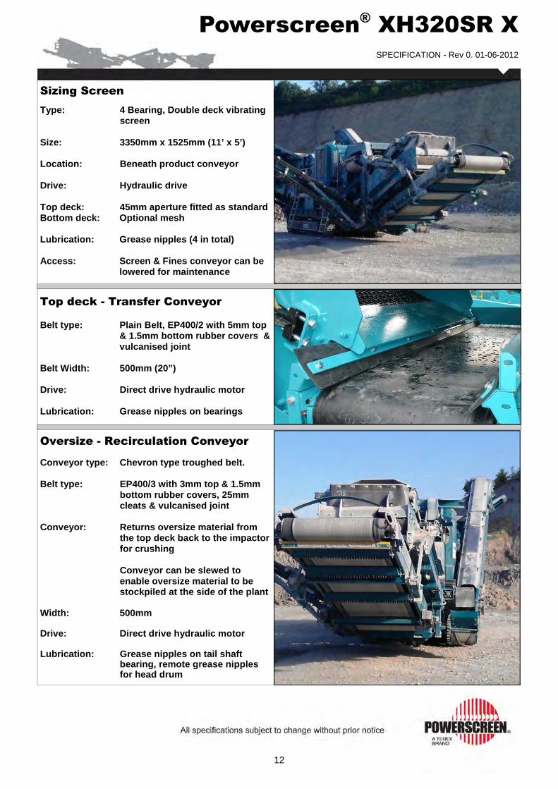
Powerscreen® XH320SR X
SPECIFICATION - Rev 0. 01-06-2012
12
Sizing Screen
Type: 4 Bearing, Double deck vibrating screen
Size: 3350mm x 1525mm (11’ x 5’) Location: Beneath product conveyor Drive: Hydraulic drive Top deck: 45mm aperture fitted as standard Bottom deck: Optional mesh Lubrication: Grease nipples (4 in total) Access: Screen & Fines conveyor can be
lowered for maintenance
Top deck - Transfer Conveyor Belt type: Plain Belt, EP400/2 with 5mm top
& 1.5mm bottom rubber covers & vulcanised joint
Belt Width: 500mm (20”) Drive: Direct drive hydraulic motor Lubrication: Grease nipples on bearings
Oversize - Recirculation Conveyor Conveyor type: Chevron type troughed belt. Belt type: EP400/3 with 3mm top & 1.5mm
bottom rubber covers, 25mm cleats & vulcanised joint
Conveyor: Returns oversize material from
the top deck back to the impactor for crushing
Conveyor can be slewed to
enable oversize material to be stockpiled at the side of the plant
Width: 500mm Drive: Direct drive hydraulic motor Lubrication: Grease nipples on tail shaft
bearing, remote grease nipples for head drum

Powerscreen® XH320SR X
SPECIFICATION - Rev 0. 01-06-2012
13
Fines - Product Conveyor Conveyor type: Plain troughed belt Belt type: EP400/2 with 5mm top & 1.5mm
bottom covers, vulcanised joint Width: 1400mm (55”) Discharge height: 2.92m (9’ 7”) Stockpile volume: 37m 3 (48 cu. yd.) Drive: Direct drive hydraulic motor Lubrication: Head drum - remote greasing,
nipples on tail shaft bearings
Bottom Deck - Transfer Conveyor Function: Transfers material from bottom
deck of sizing screen to optional plant mounted stockpiling
conveyor or re-circulating conveyor Belt type: EP400/2 with 5mm top,1.5mm bottom covers, vulcanised joint Width: 500mm (20”) Drive: Direct drive hydraulic motor Lubrication: Grease nipples on head & tail
shaft bearings
Optional Extras
� Four full size hammers in lieu of two full & two half hammers � High chrome blowbars � Ceramic Blowbars � Hydraulic folding extended hopper � Single pole overband magnetic separator � Twin pole overband magnetic separator
� Dirt conveyor � Magnet Prepared � Plant lighting � Radio remote control � Refuelling pump � Optical belt weigher � Hydraulic water pump for dust suppression (For pricing please contact your local dealer)
Feeder Underscreen Mesh Position: Replaces standard blanking mat, used in conjunction with optional side conveyor Sizes: 10,20,30,40,50mm

Powerscreen® XH320X Options
SPECIFICATION - Rev 0. 01-06-2012
14
Pan Feeder Pan type: Sprung vibrating pan Vibrating unit: Twin heavy duty cast eccentric
shafts running in spherical roller bearings, gear coupled at drive end, flange mounted hydraulic motor
Dimensions: Length: 2.15m (7’) Width: 1.08mm (3’ 6”) Pan: 12mm thick replaceable abrasion
resistant liners
Live Pre-screen
Pre-screen: Sprung vibrating unit with stepped finger bofor deck Vibrating unit: Single shaft, out of balance weights, flange mounted hydraulic motor Bofor deck: 2 stepped bolt in cartridges
50mm (2”) nominal spacing 9mm throw 1000rpm screen speed Dimensions: Length: 2.0m (6’ 7”) Width: 1.06m (36”) Mesh deck: 38mm (1.5”) nominal spacing 17º incline Dimensions: Length: 1.57m (5’ 2”) Width: 1.06m (36”) Chute: Bypass chute with internal 2 way
flap door fitted, to control direction of fines, either forward
onto the product belt or onto the optional side conveyor
(if blanking mat is fitted) Modular section: Hopper & feeder mounted on
removable modular sub frame

Powerscreen® XH320X
SPECIFICATION - Rev 0. 01-06-2012
15
Pre-Screen Hopper Hydraulic folding hopper with over centre struts Hydraulic hopper lock system operated at ground level Hopper width: 2.54 m (8’ 4”) Hopper capacity: 6.25m 3(8.2 cu. yd.) Hopper body: 8mm (0.31”) thick abrasion resistant steel plate
Pre-Screen Hopper (Extensions) Hydraulic folding hopper with over centre struts Hydraulic hopper lock system operated at ground level Hopper width: 4.0 m (13’ 2”) Hopper capacity: 9.0m 3(11.7 cu. yd.) Hopper body: 8mm (0.31”) thick abrasion resistant steel plate
Dirt Conveyor Conveyor type: Steel troughed roller, hydraulic folding Width: 650mm (26”) Discharge: 2.6m (8’ 6”) Stockpile volume: 26m 3 (85 cu. yd.) Drive: Direct drive hydraulic motor Position: Discharge on RHS of plant std LHS variant available
Extended Dirt Conveyor Conveyor type: Steel troughed roller, hydraulic folding Width: 650mm (26”) Discharge: 3.7m (12’ 2”) Stockpile volume: 75m 3 (85 cu. yd.) Drive: Direct drive hydraulic motor Position: Discharge on RHS of plant LHS variant available

Powerscreen® XH320X Options
SPECIFICATION - Rev 0. 01-06-2012
16
Midsize - Stockpiling Conveyor
Function: Stockpiles material from bottom deck, via side transfer conveyor
Conveyor type: Chevron type troughed belt Belt type: EP400/3, 3mm top, 1.5mm bottom
covers, 25mm cleats, vulcanised Width: 500mm (20”) Discharge Height: 4.45m (14’ 7”) Stockpile volume: 131m 3 (171cu. yd.) Drive: Direct drive hydraulic motor Lubrication: Head drum - remote greasing,
nipples on tail shaft bearings
Overband Magnet Magnet type: Terex TX440 Single Pole (S.P.) & Twin Pole (T.P.) available. Belt width: 750mm (30”) Centres: 1700mm (67”) Magnet block: S.P. 1050mm x 530mm (41” x 21”) T.P. 1042mm x 672mm (41” x 26”) Drive/Control: Direct drive hydraulic motor / Pre-set variable speed Weight: S.P. 975kg / T.P. 1470kg
Blowbars Two full size Martensitic & two half size Manganese blowbars Two further options are available: High Suitable for medium to hard rock Chrome: applications with no steel present in feed. Good wear characteristics Ceramic: Suitable for applications with limited steel in feed. Improved wear characteristics over standard martensitic 4 full blowbars: Available in all options

Powerscreen® XH320X Options
SPECIFICATION - Rev 0. 01-06-2012
17
Belt Weigher XH320X: Optical belt scale, monitors material volume Can be converted into mass & downloaded to hand held PDA unit via Bluetooth PDA unit included in kit XH320SR X: Single idler belt weigher with integrator & Speed-sensing wheel fitted to fines conveyor
Radio Remote Control Complete with integrated tracking functions & plant stop button NB - Only available in certain countries where type approval has been obtained Remote can also be used for: • Feeder (stop/start/speed)
• Product conveyor (raise/lower)
• Open top apron
Electric Refuelling Pump A 24 volt refuelling pump, allows fuel to be drawn from a remote source. Fuel transfer rate is 50 L/min (13 G/min)
Plant Lighting
Plant lighting kit available, contains two bi-directional working lamps. Both activated remotely from control panel

Powerscreen® XH320X
SPECIFICATION - Rev 0. 01-06-2012
18
Approximate Plant Weights & Dimensions
Working length: 16.15m (53’ 0”) Working height: 4.56m (15’ 0”) Working width: 8.6m (28’ 3”) with extended dirt conveyor deployed Total plant weight: 36,540kg (80,469lbs) * * = c/w Tier 4 Engine with Pan Feeder & Pre-screen, Hopper, Dirt and Product Conveyor extensions, Magnet Paint colour: RAL 5021
XH320X
Working Dimensions

Powerscreen® XH320SR X
SPECIFICATION - Rev 0. 01-06-2012
19
Approximate Plant Weights & Dimensions
Transport length: 17.15m (56’ 3”) Transport height: 3.4m (11’ 2”) Transport width: 3.58m (11’ 9”) Paint colour: RAL 5021
XH320SR X
Transport Dimensions

Powerscreen® XH320SR X
SPECIFICATION - Rev 0. 01-06-2012
20
Terex GB Ltd. 200 Coalisland Road
Dungannon Co. Tyrone
Northern Ireland BT71 4DR
Tel: +44(0) 28 8774 0701 Fax: +44(0) 28 8774 6569
E-Mail: [email protected]
Web: www.powerscreen.com
Terex is a registered trademark of Terex Corporation in the United States of America and many other countries. Powerscreen is a registered trademark of Terex GB Ltd in the United States of America and many other countries. Copyright Terex Corporation 20112
Powerscreen equipment complies with CE requirements. Please consult Powerscreen if you have any other specific requirements in respect of guarding, noise or vibration levels, dust emissions, or any other factors relevant to health and safety measures or environmental protection needs. On receipt of specific requests, we will endeavour to ascertain the need for additional equipment and, if appropriate, quote extra to contract prices. All reasonable steps have been taken to ensure the accuracy of this publication, however due to a policy of continual product devel-opment we reserve the right to change specifications without notice. It is the importers’ responsibility to check that all equipment supplied complies with local legislation regulatory requirements. Plant performance figures given in this brochure are for illustration purposes only and will vary depending upon various factors, including feed material gradings and characteristics. Information relating to capacity or performance contained within this publication is not intended to be, nor will be, legally binding.

Dowsing Inert Recycling Facility
Acoustics - Noise Emissions Compliance of Inert Material Crushing Activity
D EQUIPMENT CALIBRATION CERTIFICATES
© SEALHURST PTY LTD All Rights Reserved SEA-2013-028 RPT001
D. EQUIPMENT CALIBRATION CERTIFICATES

Dowsing Inert Recycling Facility
Acoustics - Noise Emissions Compliance of Inert Material Crushing Activity
E NOISE DURING CONSTRUCTION PHASE
© SEALHURST PTY LTD All Rights Reserved SEA-2013-028 RPT001
E. NOISE DURING CONSTRUCTION PHASE
E.1 Extract from Appendix D AS 2436 - Section 4.6
AS2436:2010 Appendix D
Section 4.6
In demolition work alongside occupied premises there should, if possible, be a break in solid connections, e.g. concrete paving, between the working area and the adjoining buildings. This will reduce the transmission of vibration and structure-borne noise. Care should be taken that any such break is of no structural significance in relation to the planned system of demolition. The break could result in premature collapse due to lack of continuity or restraint. Care should be taken not to drop materials from a height either into or out of trucks. The surfaces on to which the materials are being moved should be covered by some resilient material. Particular care should be taken during the loading and unloading of scaffolding. Where material cannot be lowered in skips or by other means, it is recommended that properly constructed and damped chutes be used. The effectiveness of noise enclosures and screens can be partially lost if they are used incorrectly. For example, the noise being enclosed should be directed into and not out of the enclosure. There should also be no reflecting surfaces opposite the open side.
4.5.5 Maintenance of equipment Increases in plant noise are often indicative of future mechanical failure. Regular and effective maintenance of plant and equipment including vehicles is essential and will do much to maintain noise levels near to that of new plant. Maintenance should be carried out only by trained persons. Where maintenance work has to be done at night, precautions may be necessary to minimize any nuisance. Vibration from machinery with rotating parts can be reduced by attention to proper balancing. Frictional noise from the cutting action of tools and saws may be reduced if the tools are kept sharp. Other noises caused by friction in machines, conveyor rollers and trolleys can be reduced by proper lubrication.
4.6 CONTROLLING THE SPREAD OF NOISE
4.6.1 General
If noisy processes cannot be avoided, then the amount of noise reaching the receiver should be minimized. Two ways of doing this are either to increase the distance between the noise source and the receiver or to introduce noise reduction measures such as screens. Physical methods to reduce the transmission of noise between the site works and residences, or other sensitive land uses, are generally suited to works where there is longer-term exposure to the noise. Practices that will reduce noise from the site include: (a) Increasing the distance between noise sources and sensitive receivers. (b) Reducing the line-of-sight noise transmission to residences or other sensitive land uses using temporary barriers (stockpiles, shipping containers and site office transportables can be effective barriers). (c) Constructing barriers that are part of the project design early in the project to afford mitigation against site noise. (d) Installing purpose built noise barriers, acoustic sheds and enclosures.
4.6.2 Distance
Increasing the distance is often the most effective method of controlling noise. This may not be possible where work takes place on fixed structures, e.g. railway tracks. The effect of distance on noise levels is explained in Appendix B. Stationary plant such as compressors and generators can be located away from the work area so as to avoid being close to any noise-sensitive area.

Dowsing Inert Recycling Facility
Acoustics - Noise Emissions Compliance of Inert Material Crushing Activity
E NOISE DURING CONSTRUCTION PHASE
© SEALHURST PTY LTD All Rights Reserved SEA-2013-028 RPT001
4.6.3 Screening
On sites where distance is limited, the screening of noise may be of benefit and this should be taken into account at the planning stages. Appendix B illustrates the effect of the screen in reducing the noise level and Appendix D describes the performance of different types of acoustic screens and enclosures and the materials they are made of. If structures such as stores, site offices and other temporary buildings are situated between the noisiest part of the site and the nearest dwellings, some of the noise emission from the site can be reduced. If these buildings are occupied, then sound insulation measures may be necessary to protect workers in them.
A hoarding that includes a site office on an elevated structure offers a superior noise reduction when compared with a standard (simple) hoarding. This performance is further enhanced when the hoarding is a continuous barrier. Storage of building materials or the placement of shipping containers between the noise source and any noise-sensitive area may also provide useful screening and the same is true of partially completed or demolished buildings.
Noisy stationary plant can be put in a basement, the shell of which has been completed, provided reverberant noise can be controlled. Where compressors or generators are used in closed areas, it is necessary to ensure that the exhaust gases are discharged directly to the outside air and that there is good cross-ventilation to prevent the build-up of poisonous carbon monoxide fumes and to allow an adequate air supply to maintain efficient running.
Where such noise barriers are not practicable, a worthwhile reduction in noise can be obtained by siting the plant behind and as close as possible to mounds of earth, which may effectively screen the plant from any noise-sensitive areas. These can often be designed into the construction schedule or site arrangement for future landscaping. Water pumps, fans and other plant and equipment that operate on a 24-hour basis may not be a source of noise nuisance by day but can create problems at night. They should therefore be effectively screened either by being sited behind a noise barrier or by being positioned in a trench or a hollow in the ground provided this does not generate reverberant noise. In such cases, however, adequate ventilation should also be ensured.
Long, temporary earth embankments can provide quite an effective noise screen for mobile equipment moving, for example, on a haulage road. When the earthworks are complete, the earth mounds should be removed if possible with smaller, quieter excavators. A noise barrier may be a more reliable method of noise control than the imposition of restrictions on throttle settings. In many cases it will not be practicable to screen earthmoving operations effectively, but it may be possible to partially shield construction plant or to build-in at the early stages protective features ultimately required to screen traffic noise. Where earth noise barriers are not a practical proposition because of lack of space, consideration should be given to the possibility of constructing temporary screens from wood or any of the materials suggested in Appendix D.
The usefulness of a noise barrier will depend upon its length, its height, its position relative to the source and to the listener, and the material from which it is made. A barrier designed to reduce noise from a moving source should extend beyond the last property to be protected to a distance of not less than ten times the shortest measurement from the property to the barrier. A barrier designed to reduce noise from a stationary source should, where possible, extend to a distance beyond the direct line between the noise source and the receiver to a distance equal to ten times the effective barrier height, which is the height above the direct line between source and receiver. If the works are predominately within nominally closed structures, careful consideration should be given to reducing noise breakout at any openings.

Dowsing Inert Recycling Facility
Acoustics - Noise Emissions Compliance of Inert Material Crushing Activity
E NOISE DURING CONSTRUCTION PHASE
© SEALHURST PTY LTD All Rights Reserved SEA-2013-028 RPT001
4.7 CONTROL OF NOISE AT THE RECEIVER
In cases where noise emissions cannot be adequately controlled at the source or by controlling the spread of noise, consideration should be given to control of noise received at nearby sensitive locations. Provision of treatments at the affected residence or other sensitive land use is normally only suited to addressing noise from longer term construction projects at a stationary site, or where the work site is relatively isolated, or where only a few residences or other sensitive land uses are affected.
Practices that will mitigate the impacts of noise include: (a) Providing localized noise barriers adjacent to the receiving location. (b) Providing acoustic insulation to reduce airborne noise entering buildings, for example, heavyweight glazing or double glazing. (c) Providing ventilation to enable windows and doors to remain closed. (d) Providing access to temporary relocation for noise-affected occupants for short periods, for example, when high noise levels from construction occur at night and there are no feasible and reasonable ways of reducing noise levels.
4.8 CONTROL OF VIBRATION
4.8.1 General
Vibration can be more difficult to control than noise, and there are few generalizations that can be made about its control. It should be kept in mind that vibration may cause disturbance by causing structures to vibrate and radiate noise in addition to perceptible movement. Impulsive vibration can, in some cases, provide a trigger mechanism that could result in the failure of some building component that had previously been in a stable state. It can also trigger annoyance being elevated into action by occupants of exposed buildings, and should therefore be included in planning of communication with impacted communities.
It should be remembered that failures, sometimes catastrophic, can occur as a result of conditions not directly connected with the transmission of vibrations, e.g. the removal of supports from retaining structures to facilitate site access. BS 7385-2 provides information on managing groundborne vibration and its potential effects on buildings.
Where site activities may affect existing structures, a thorough engineering appraisal should be made at the planning stage. General principles of seeking minimal vibration at receiving structures should be followed in the first instance. Predictions of vibration levels likely to occur at sensitive receivers is recommended when these are relatively close, depending on the magnitude of source of the vibration or the distance involved. Relatively simple prediction methods are available in texts, codes of practice or other standards, however it is preferable to measure and assess site transmission and propagation characteristics between source and receiver locations.
Comparison of predicted levels of vibration with preferred or regulatory levels will indicate when either more detailed predictions are required or mitigation of transmitted vibration is advisable or necessary. Guidance in measures available for mitigation of vibration transmitted can be sought in more detailed standards, such as BS 5228-2 or policy documents, such as the NSW DEC Assessing Vibration: A technical guideline.
Identifying the strategy best suited to controlling vibration follows a similar approach to that of noise—of avoidance, control at the source, control along the propagation path, control at the receiver, or a combination of these. It is noted that vibration sources can include stationary plant (pumps and compressors), portable plant (jackhammers and pavement vibrators), mobile plant, pile-drivers, tunnelling machines and activities, and blasting, amongst others. Unusual ground conditions, such as a high water-table, can also cause a difference to expected or predicted results, especially with piling.

Dowsing Inert Recycling Facility
Acoustics - Noise Emissions Compliance of Inert Material Crushing Activity
F ACOUSTIC GLOSSARY
© SEALHURST PTY LTD All Rights Reserved SEA-2013-028 RPT001
F. ACOUSTIC GLOSSARY
Acoustic Measurement Parameter Definitions
dB
Decibel: a logarithmic scale applied to acoustic units such as sound pressure and sound power. Decibels are
always the ratio between two numbers. Sound Pressure in Pascals becomes "Sound Pressure Level re 2x10⁻⁵ Pa"
in decibels. Sound Power in watts becomes "Sound Power Level re 10-12 W" in decibels. It is
also used for sound reduction or sound insulation and is the ratio of the amount of sound energy incident upon a
partition and the proportion of that energy which passes through the partition. The result is stated as a "decibel
reduction".
dB(A)
A- weighting: This is an electronic filter which attenuates sound levels at some frequencies relative to the sound
levels at other frequencies. The weighting is designed to produce the relative response of a human ear to sound
at different frequencies. The A-weighted sound level is therefore a measure of the subjective loudness of sound
rather than physical amplitude. A- weighting is used extensively and is denoted by the subscript A as in LA10, LAeq
etc. (Levels given without the subscript A are linear sound levels without the A- weighting applied, e. g. L10, Leq
etc.).
LAeq,T
The “A” weighted equivalent continuous sound pressure level. This may be thought of as the "average" sound
level over a given time “T”. It is used for assessing noise from various sources: industrial and commercial
premises, construction sites, railways and other intermittent noises.
LA90,T
The “A” weighted sound pressure level that is exceeded for 90% of the time T. It reflects the quiet periods
during that time and is often referred to as the "background noise level". It is used for setting noise emission
limits for industrial and commercial premises.
LAmax
The maximum "A" weighted sound pressure level during a given time on fast or slow response.
LpA
The "A" weighted sound pressure Level. The sound pressure level is filtered through a standard frequency
weighting known as A-weighting. This filter copies the frequency response of the human ear, so that the
resulting sound level closely represents what people actually hear.
R
Is the sound reduction index of a construction element in octave or 1/3 octaves and can only be measured in a
laboratory. There must be no flanking transmission.
R'
Is the sound reduction index of a construction element in octave or 1/3 octaves measured on site, and normally
includes flanking transmission (ie where sound travels via paths other than straight through the element being
tested, such as columns, ducts, along external walls, etc).

Dowsing Inert Recycling Facility
Acoustics - Noise Emissions Compliance of Inert Material Crushing Activity
F ACOUSTIC GLOSSARY
© SEALHURST PTY LTD All Rights Reserved SEA-2013-028 RPT001
Rw
To get the weighted sound reduction index (Rw) of a construction, the R values are measured in octave or 1/3
octave bands covering the range of 100Hz to 3150Hz. The curve is adjusted so that the unfavourable deviation
(or shortfall of the actual measurements below this standard curve) averaged over all the octave or 1/3 octave
bands is not greater than 2dB. The value of the curve at 500Hz is the Rw.
R’w
The apparent sound reduction index, which is determined in exactly the same way as the Rw but on site where
there is likely to be some flanking transmission.
D
This is the "level difference". It is determined by placing a noise source in one room and measuring the noise
levels in that room (the "source room") and an adjacent room (the "receiver room"). The level difference is
calculated by simply deducting the "receiver" noise level (dB) from the "source" noise level (dB).
Dw
This is the weighted level difference. D is measured on site in octave or 1/3 octave bands covering the range of
100Hz to 3150Hz. The D values are compared to a standard weighting curve. The curve is adjusted so that the
"unfavourable deviation" (or shortfall of the actual measurements below this standard curve) averaged over all
the octave or 1/3 octave bands is not greater than 2dB. The Dw is then the value of the curve at 500Hz.
Dnw
This is the weighted normalised level difference. D is measured on site in octave or 1/3 octave bands covering the
range of 100Hz to 3150Hz. As the level difference is affected by the area of the common wall/ floor and the
volume of the receiving room, as well as the amount of absorption in the receiving room, in the case of the DnT,w,
the results are "normalised" by a mathematical correction to 10m2 of absorption (Dn). The same weighting curve
as for Dw is used to obtain the single figure: Dnw.

Dowsing Inert Recycling Facility
Acoustics - Noise Emissions Compliance of Inert Material Crushing Activity
F ACOUSTIC GLOSSARY
© SEALHURST PTY LTD All Rights Reserved SEA-2013-028 RPT001
Acoustic Performance Guide
DnT,w
This is the weighted standardised level difference. D is measured on site in octave or 1/3 octave bands covering
the range of 100Hz to 3150Hz. As the level difference is affected by the area of the common wall/ floor and the
volume of the receiving room, as well as the amount of absorption in the receiving room, in the case of the DnT,w,
the results are "standardised" by a mathematical correction a reverberation time, usually 0.5 seconds (DnT). The
same weighting curve as for Dw is used to obtain a single figure "DnT,w"
DnT(Tmf, max),w
This is the weighted BB93 standardised level difference corresponding to a Building Bulletin 93 reference value
reverberation time in a receiving room. It is measured on site in accordance with BS EN ISO 140- 4: 1998.
Dn,c
Suspended ceiling normalised level difference. This is the sound level difference between two rooms, separated
by a suspended ceiling, normalised to a reference value of absorption in the receiving room (10m2 for the
Laboratory as specified in ISO 140- 9 : 1985). It is measured in 1/3 octave or octave frequency bands.
Dn,c,w
Weighted suspended ceiling normalised level difference. This is a single number quantity representing the sound
reduction between two rooms separated a suspended ceiling. It is obtained by applying specified weightings to
the 1/3 octave band suspended ceiling normalised level differences in the frequency range 100Hz to 3150Hz.
Ctr
Spectrum adaptation term: Value, in decibels, to be added to a single- number rating (e. g. Rw) to take account
of the characteristics of particular sound spectra. Ctr is calculated using an A- weighted urban traffic noise
spectrum as defined in BS EN ISO 717- 1 : 1997.
NR
Stands for Noise Rating. (It is NOT noise reduction). It is (e. g. NR30, NR35 etc.) a single number, which
represents the sound level in a room and takes account of the frequency content of the noise. The lower the NR
value, the quieter the room will be. It is mainly used for assessing noise from mechanical services systems. In
leisure developments it is used as a standard for noise break- in to rooms from external noise sources such as
traffic.
NC
Stands for Noise Criteria. It is very similar to NR but (e.g. NC30, NC35 etc.) uses slightly different frequency
weightings.
NRC
Stands for Noise Reduction Coefficient. The noise reduction coefficient of a material is the average, to the
nearest multiple of 0.05, of the absorption coefficients at 250Hz, 500Hz, 1kHz and 2kHz.
Dowsing Inert Recycling Facility
Acoustics - Noise Emissions Compliance of Inert Material Crushing Activity
F ACOUSTIC GLOSSARY
© SEALHURST PTY LTD All Rights Reserved SEA-2013-028 RPT001
α
Stands for Absorption Coefficient, which represents the proportion of incident sound energy arriving from all
directions that is not reflected back into the room. It ranges between 0 and 1, where 0 is reflective and 1 is totally
absorptive.
αw
Stands for Weighted Absorption Coefficient. Single- number frequency dependent value which equals the value
of the reference curve at 500Hz after shifting it as specified in EN ISO 11654 :1997.
αp
Stands for practical absorption factor. It is a frequency dependent value of sound absorption coefficient which is
based on measurements in one- third- octave bands in accordance with ISO 354 and which is calculated in octave
bands in accordance with EN ISO 11654 : 1997. It is the arithmetic mean of the three 1/3 octave sound
absorption coefficients within the octave being considered. The mean value is calculated to the second decimal
place and rounded in steps of 0.05 up to a value of 1.0.
Class X
Stands for the Absorption Class between 250 and 4kHz, as defined by EN ISO 11654. Class A is the best
classification representing the highest level of absorption, and Class E offers to lowest classification.
RT or T60
Reverberation Time is a measure of the echoic nature of a room. It is normally measured in 1/3 octave or 1/1
octave bands by creating a loud noise and measuring the time it takes for that noise to decay by 60dB. The
longer the reverberation time, the more ‘echoey’ a room sounds. For dwellings, a reverberation time of 0.5
seconds or less is normal. Cinema auditoria will have reverberation times of 1.0 second or below when fitted out,
but up to 9 seconds at shell completion.
When designing acoustically sensitive areas such as concert halls or lecture theatres, it is necessary to design the
room finishes to achieve optimum reverberation times. These will vary depending on the type of activity in the
room and the room volume.
Tmf
Stands for the arithmetic average of the reverberation times in the 500Hz, 1kHz and 2kHz octave bands, for the
type of receiving room, as defined in UK Schools design manual, Building Bulletin 93.