ENVE 302 Environmental Engineering Unit Processesmimoza.marmara.edu.tr/~bilge.alpaslan/ENVE...
41
1 ENVE 302 Environmental Engineering Unit Processes Assist. Prof. Bilge Alpaslan Kocamemi Marmara University Department of Environmental Engineering Istanbul, Turkey CHAPTER: 4 Activated Sludge Processes
Transcript of ENVE 302 Environmental Engineering Unit Processesmimoza.marmara.edu.tr/~bilge.alpaslan/ENVE...
1
ENVE 302
Environmental Engineering Unit Processes
Assist. Prof. Bilge Alpaslan Kocamemi
Marmara University
Department of Environmental Engineering
Istanbul, Turkey
CHAPTER: 4
Activated Sludge Processes

Suspended Growth (Activated Sludge)
Treatment Process Configurations
Basic activated sludge process consists of the following 3 basic components:
1. A reactor in which the microorganism responsible for treatment are kept in suspension and aerated
2. Liquid-solids seperation in a sedimentation tank
3. A recycle system for returning solids removed from the liquid-solids seperation unit back to the reactor (to maintain a sufficient conc of biomass in the aeration tank)
2

Types of activated-sludge process
(i) Complete mix reactors
(ii) Plug flow reactors
(iii) Sequencing batch reactors
3

4
Complete mix activated sludge processes tank contents are throughly mixed
substrate load
MLVSS conc oxygen demand substrate conc. in the effluent is same as the substrate conc. in the reactor
relatively simple to operate but to have low organic subs. conc. (i.e low F/M) that encourage the growth of filamentous bacteria causing sludge bulking
uniform throughout the tank

care should be taken to prevent short-circuiting of untreated or partially treated ww
(influent and effluent withdrawal points selection are important)
If shock loads or toxic discharges (large number of industrial connections) are a
design consideration
a complete mix reactor can more easily withstand changing ww
characteristics because the incoming ww is more or less uniformly
dispersed with the reactor contents
Complete mix reactors are superior to plug flow reactors where wide
fluctuations in flow rates occur 5

however, in actual practice, a true plug flow regime is essentially impossible to obtain because of longitudinal dispersion caused by aeration & mixing
by dividing the aeration tank
into a series f reactors
(staged reactor desing)
process approaches plug flow kinetics
with improved treatment efficiency
compared to a complete mix process
6
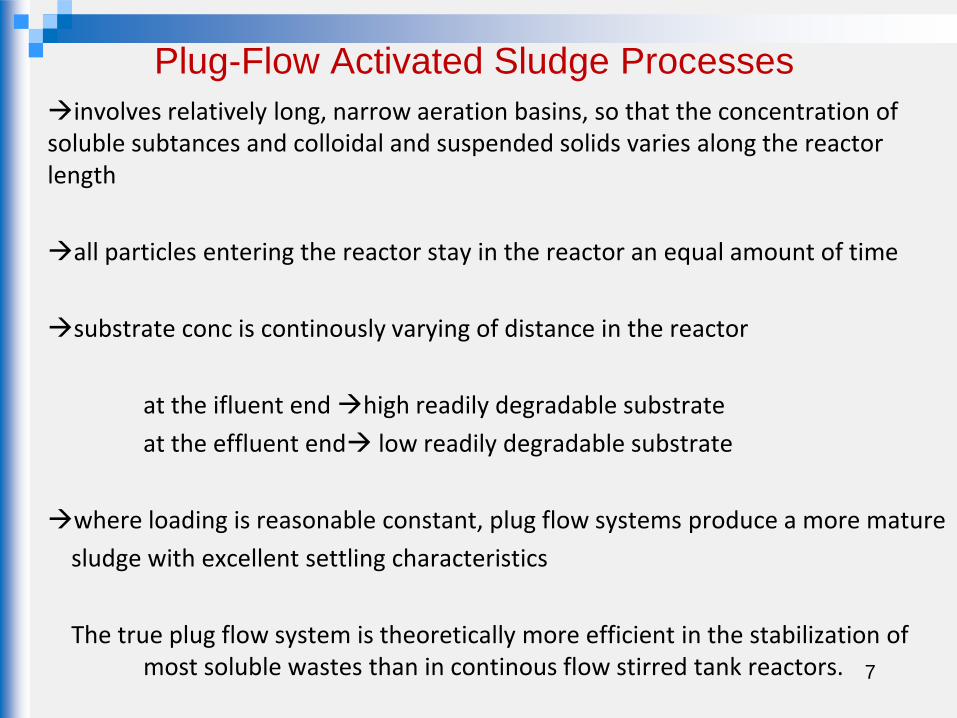
Plug-Flow Activated Sludge Processes
involves relatively long, narrow aeration basins, so that the concentration of soluble subtances and colloidal and suspended solids varies along the reactor length
all particles entering the reactor stay in the reactor an equal amount of time
substrate conc is continously varying of distance in the reactor
at the ifluent end high readily degradable substrate
at the effluent end low readily degradable substrate
where loading is reasonable constant, plug flow systems produce a more mature
sludge with excellent settling characteristics
The true plug flow system is theoretically more efficient in the stabilization of most soluble wastes than in continous flow stirred tank reactors.
7

8
In actual practice, a true plug flow regime is essentially impossible to obtain because of longitudinal dispersion caused by aeration & mixing
By dividing the aeration tank
into a series of reactors
(staged reactor design)
Process approaches plug flow kinetics
with improved treatment efficiency
compared to a complete mix process
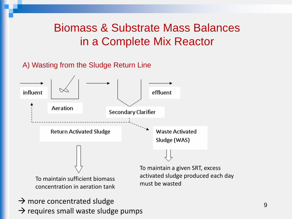
Biomass & Substrate Mass Balances
in a Complete Mix Reactor
more concentrated sludge requires small waste sludge pumps
A) Wasting from the Sludge Return Line
To maintain sufficient biomass concentration in aeration tank
To maintain a given SRT, excess activated sludge produced each day must be wasted
9

B) Wasting from the Aeration Tank
At the bottom of
secondary clarifiers
anaerobic conditions
may develop
Release of
phosphorus
Withdrawal of mixed liquor (ww+biomass) directly from aeration tank
Less concentrated
Good method if the process includes phosphorus removal
10

Solids Retention Time (SRT) mean cell residence time, sludge age , Ѳc
The sludge or biomass requires a certain amount of time to assimilate the substrate and reproduce
If the sludge is not able to reproduce itself
before being washed out of the system
The ave period of time during which the sludge has remained in the aeration tank
SRT or Ѳc
Residence time of sludge in the clarifier does not contribute to the effective sludge age
no substrate in sec clarifier
low DO conc
metabolic activity of sludge is not significant
failure will result
11

removal
wasting from RAS line or directly from aeration basin
m.o overflowing the secondary clarifier weir into effluent
(i.e. m.o. escaping from secondary clarifier)
The SRT (solids retention time) is completely anologous to HRT (hydraulic retention
time)
However ; HRT and SRT are very different
(Ѳ) HRT is on the orders of hours
(Ѳc) SRT is on the orders of days To achieve this, cells (microorganisms)
are recyled from clarifier over and over
again
daily removed organisms of
ankaeration t in the organisms of
mass
mass)(SRT c

For the case of aeration tank with no clarifier and thus no sludge recyle
QX
VXc
SRT is the most critical paramater for activated – sludge design
It affects :
• treatment process performance
• aeration tank volume
• sludge production
• oxygen requirements
13

SRT min (Ѳc min) critical value
It is the residence time at which the cells are washed out or wasted from the system
faster than they can reproduce
To ensure adequate waste treatment, biological treatment processes are usually
designed and operated with SRT=2-20 SRTmin
14

Treatment goal SRT
Range, d
Factors affecting SRT
Removal of soluble BOD
in domestic wastewater
1-2 Temperature
Conversion of particulate
organics in domestic
wastewater
2-4 Temperature
Develop flocculent
biomassfor treating
domestic wastewater
1-3 Temperature
Develop flocculent
biomassfor treating
industrial wastewater
3-5 Temperature/ compounds
Provide complete
nitrification
3-18 Temperature/ compounds
Biological phosphorus
removal
2-4 Temperature
Stabilization of activated
sludge
20-40 Temperature
Degradation of
xenobiotic compounds
5-50 Temperature/ specific
bacteria/ compounds
Table 8-6
Typical minimum SRT ranges for activated sludge treatment
* Adapted from Grady et al. (1999)
Ref: Metcalf & Eddy

A) Mass Balance for the system including wasting from the Sludge Return Line
QR,XR,S
Qw,XR,S
Qe,Xe,S
S,X,
16
System
boundary
Qo,So,Xo
'gRwewo rXQXQQQX
dt
dX
Biomass Mass Balance
Accumulation = Inflow - Outflow + Generation

17
'gRwewo rXQXQQQX
dt
dX
Assumption: 1) the conc. of m.o in the influent is negligible 2) steady-state conditions prevail
1kYk
k1KeffluentS
dc
cds concsubst (Yk=µm)

18
Accumulation = Inflow - Outflow + Generation
suweo rSQSQQSdt
dS
QR,XR,S
Qw,XR,S
S,X,
System
boundary
Substrate Mass Balance

19
Assumption: 1) the conc. of m.o in the influent is negligible 2) steady-state conditions prevail
cd
oc
k1
SSYX
suweo rSQSQQSdt
dS

20
QR,XR,S
Q,Xo,So
Qw,X,S
(Q-QW),Xe,S
Biomass Mass Balance
Accumulation = Inflow - Outflow + Generation
'gwewo rXQXQQQX
dt
dX
B) Mass Balance for the system including wasting from the aeration tank

21
'gwewo rXQXQQQX
dt
dX
Assumption: 1) the conc. of m.o in the influent is negligible 2) steady-state conditions prevail
1kYk
k1K.effS
dc
cdsconc. subst.

22
QR,XR,S
Q,Xo,So
Qw,X,S
Substrate Mass Balance
Accumulation = Inflow - Outflow + Generation
suweo rSQSQQSdt
dS

23
Accumulation = Inflow - Outflow + Generation
suweo rSQSQQSdt
dS
Assumption: 1) the conc. of m.o in the influent is negligible 2) steady-state conditions prevail
cd
oc
k1
SSYX

Solids Production
24
Total MLVSS conc in the aeration tank, XT
= biomass conc + non – biodegradable VSS conc
X Xİ
nbVSS from cell debris
nbVSS in the influent

25
cio
c
io XQXmgn ,,3)/(influent in the bVSS
Ci,oc
cd
ocdd
cd
oCT
X
k1
SSYkF
k1
SSYX
cd
oc3
k1
SSY)m/g,X.concBiomass ( (from substrate mass balance)
nbVSS from cell debris (g/m3) = Fd kd X θc
ccd
ocdd
k1
SS(YkF
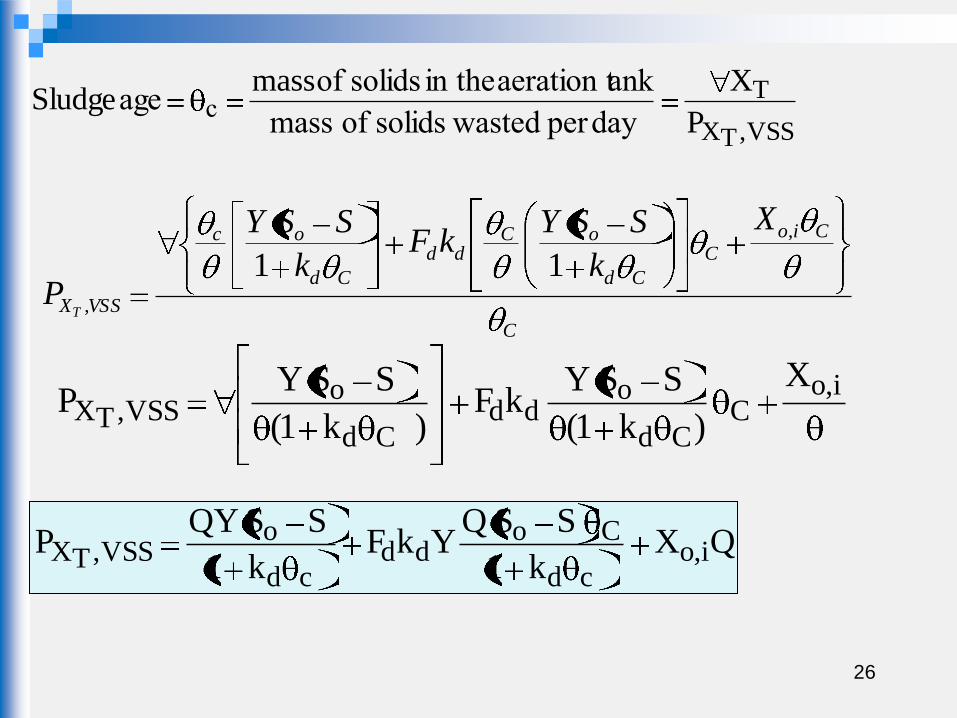
26
VSS,TX
T
P
XmassSludge
dayper wastedsolids of mass
ankaeration t in the solids of age c
C
Cio
C
Cd
oCdd
Cd
oc
VSSX
X
k
SSYkF
k
SSY
PT
,
,
11
i,oC
Cd
odd
Cd
oVSS,TX
X
)k1(
SSYkF
)k1(
SSYP
QXk1
SSQYkF
k1
SSQYP i,o
cd
Codd
cd
oVSS,TX

27
)VSSTSS(QQXTSS/VSS
k1
SSQYkF
TSS/VSS
k1
SSQY
P 00i,ocd
Codd
cd
o
TSS,TX
VSS,TX
VSS
TSS,TX
TSSC
P
VX
P
VX
QXk1
SSQYkF
k1
SSQYP i,o
cd
Codd
cd
oVSS,TX
28
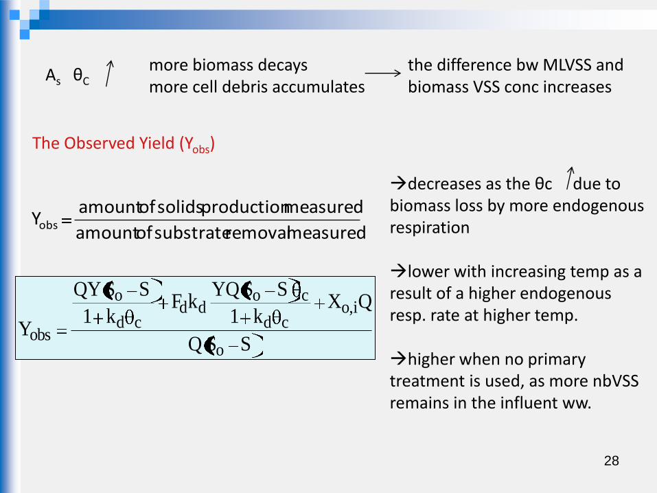
As θC more biomass decays more cell debris accumulates
the difference bw MLVSS and biomass VSS conc increases
The Observed Yield (Yobs)
measured removal substrateof amount
measured production solidsof amountYobs
decreases as the θc due to biomass loss by more endogenous respiration lower with increasing temp as a result of a higher endogenous resp. rate at higher temp. higher when no primary treatment is used, as more nbVSS remains in the influent ww.
SSQ
QXk1
SSYQkF
k1
SSQY
Yo
i,ocd
codd
cd
o
obs

29
eatmentprimary tr without 0.5-0.3
eatmentprimary tr with 3.01.0S
X
o
i,o
SS
X
k1
Ykf
k1
YY
o
i,o
cd
cdd
cdobs
Biomass cell debris influent nbVSS conc.
depends on ww characteristics & type of pretreatment S<<So
SSQYP oobsVSS,XT
SSQ
QXk1
SSYQkF
k1
SSQY
Yo
i,ocd
codd
cd
o
obs

30
F/M (Food / Microorganism) Ratio
X
QS
M
F obiomass microbial total
rate substrate applied total
Q influent flowrate (m3/d)
So influent BOD or bsCOD conc (g/m3)
X mixed liquor biomass conc. in the aeration tank (g/m3)
aeration tank volume (m3)
X
SS
X
/SSspecificU oo
X
r raten utilizatio substrate su
E= process BOD or bsCOD removal eff %= 100S
SS
0
0

31
100X
QS
)100(X
S
100S
SSX
SS
E
U oo
o
o
o
100
MF
E
U
F/M 0.1 – 0.05 g BOD/ g VSS.d (for ӨC=20 – 30 d)
0.3 – 0.5 g BOD/g VSS.d (for ӨC=5 – 7 d)
100
EMFU

Return Sludge Pumping Rate
32
QR,XR,S
Qw,XR,S
(Q-QW),Xe,S
S,X,
System
boundary
Q,Xo,So
Q+QR
X
A) Wasting from the Secondary Clarifier

33
Biomass Mass Balance around secondary clarifier
Accumulation = Inflow - Outflow + Generation
Rrrweer XQXQXQX)QQ(dt
dX
Assumption: 1) steady-state conditions prevail 2) solids in the effluent from the settling tank is negligible

34
RRRweeR XQXQXQX
QQ0
dt
dx
RRRWR XQXQXQQX
RwRwewc
XQ
X
XQXQQ
X(for wasting from RAS)
c
Rw XXQ
RR
c
R XQXXQQX
35
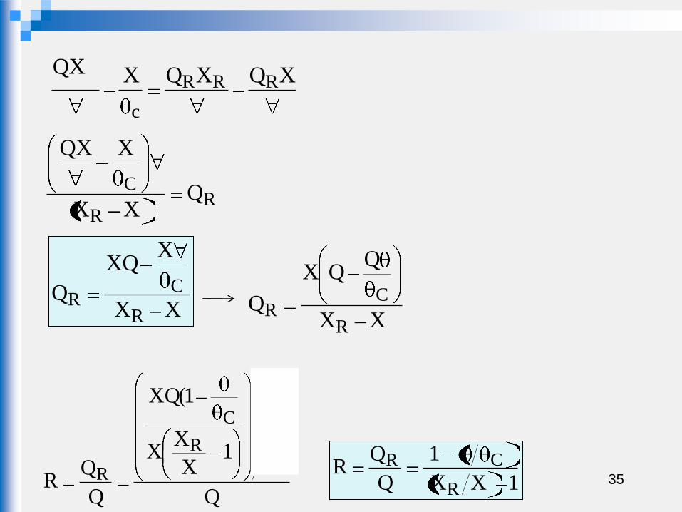
XQXQXQXRRR
c
RR
C QXX
XQX
XX
XXQ
QR
CR
XX
QQX
QR
CR
Q
1X
XX
1(XQ
Q
QR
R
C
R 1XX
1
Q
QR
R
CR

36
If you write biomass mass balance around aeration tank (boundary cond : black dotted line)
Accumulation = Inflow - Outflow
XQQXQQXdt
dxRRR0
Assumptions: 1) steady-state conditions prevail 2) X0 is negligible 3) new cell growth is negligible
XQQXXQ0 RRR
XXQQX RR
XX
X
Q
QR
R
R

37
B) Wasting from the Aeration Tank
QR,XR,S
Q,Xo,So
Qw,X,S
(Q-QW),Xe,S
Biomass Mass Balance
Accumulation = Inflow - Outflow + Generation
)XQXQ(XQQQdt
dXRReewR
Assumptions: 1)solids in the eff from the settling tank is negligible 2) steady-state conditions prevail
Q+Qr-Qw

38
rRewR XQXeQXQQQ0
dt
dx
RRWR XQXQXQQX0
RRW XXQQXXQ
RR
C
XXQQXX
RC
R XXQXX
Q
XX
XQX
QR
CR
Recyle ratio= 1XX
/1
Q
QR
R
CR

39
Determination of Biomass Conc. in the Return Sludge (XR)
SVI (Sludge Volume Index) settleability test method often used to control the rate of return sludge pumping
SVI Volume occupied by 1g of sludge after 30 min of settling
•Mixed-liquor sample is placed in a 1 to 2-L cylinder
•MLSS conc. of the sample is determined
•Settled volume after 30 min is measured
g
ml
mg/L solids suspended
ml/L sludgeof volume settledSVI
SVI ≈ 100 ml/g considered a good settling sludge
SVI>150 ml/g associated with filementous growth sludge bulking problem

40
Example: A mixed – liquor sample with a 3000mg/L TSS conc settles to a volume of 300mL in 30 min in a 1 L cylinder SVI=?
g
ml100
g
mg1000
mg
ml1.0
L/mg3000
L/ml300SVI
RXml
g
SVI
1
g
mlSVI
SVI
210X
,approachATVIn
SVI
10X
g1
mg1000
L1
ml1000
ml
gX
3/16
R
6
R
R
43.0300010000
3000
XX
X
Q
QR
L/mg10000100
10X
SVI
10X
R
R
6
R
6
R

Ref: Metcalf & Eddy