SENG SENG 637637 Dependability Reliability Dependability ...

69Enhanced Security and Dependability in Process Bus Protection Systems
1. IntroductionPower system protection is a mission-critical application with demanding requirements in terms of security, dependability and availability.
This paper reports on a new generation protection and control platform designed for enhanced security, dependability and availability. This system is based on traditionally defined protective relays with data acquisition through fully duplicated remote I/O devices (merging units). The I/O devices are deployed directly on or in close proximity to the primary equipment. They communicate their input signals including ac sampled values, contact statuses, and a variety of transducer inputs and execute the trip and control commands using process bus. Message formats are as defined in IEC 61850 [1]. To improve overall system reliability, availability and performance for the task of protection and control, the system does not include any active (switched) communication networks, but is based on simple, dedicated point-to-point Ethernet connections with extensive self-monitoring and inherent security. In particular, by not having active Ethernet infrastructure, the system is not vulnerable to cyber security threats through its process bus.
This paper reviews requirements and practical design solutions for electronics acting as an I/O structure of a protection system when installed in a high voltage switchyard environment, using the above mentioned new protection platform to illustrate the design challenges and solutions. These challenges include temperature requirements, weather proofing, electrical and magnetic fields, conducted and radiated interference, mechanical shock and vibration, and similar conditions. These requirements are applied to mechanical packaging, fiber connectivity, copper wiring connectivity, printed circuit boards, electronic components, internal data buses, and software architecture.
Traditionally, microprocessor-based relays incorporate a certain degree of internal self-diagnostics and checking to guard against internal problems that could potentially result in a false operation or a failure to trip. Extra dependability is achieved in applications using multiple relays in parallel redundancy, while additional security may be implemented by using multiple relays in a voting scheme. The paper describes the implementation of self-testing and redundancy in the presented system, which makes it secure and dependable well beyond the realm of traditional protection and control devices.
In summary, the system reported on features greatly improved immunity to failures of its components, considerably reducing
the danger of false tripping while enhancing dependability. The subject of this paper is not just a concept but also a new technical solution now available commercially, and backed up by significant development and testing efforts [2].
2. System Aspects for Reliability, Security and DependabilityIn general, the function of a protection system is to limit the severity and extent of system disturbances and possible damage to system equipment. These objectives can be met only if protection systems have a high degree of dependability and security. In this context dependability relates to the degree of certainty that a protection system will operate correctly when required to operate. Security relates to the degree of certainty that a protection system will not operate when not required to operate. The relative effect on the bulk power system of a failure of a protection system to operate when desired versus an unintended operation should be weighed carefully in selecting protection system design parameters. Often increased dependability (fewer failures to operate) results in decreased security (more unintended operations), and vice versa [3].
Another important reliability index for protection and control systems is the attendance rate, the expectation of the number of instances where the system needs to be repaired, re-verified, upgraded, etc. per unit time. With each such instance, in addition to the cost of labour to schedule, prepare for and perform the work, and the cost of any required power element outage, there is a finite probability that an error will occur resulting in an undesired trip operation during restoration to service or afterward. Trips are of special concern where generation is tripped or load curtailed. Infrequent but still of concern is the possibility that a widespread blackout can result, such as occurred on February 26 2007 in Florida [4]. Increased redundancy means an increased number of components, and as each component failure requires a repair attendance, the failure rate of each component contributes to the total attendance rate.
Dependability and security can be obtained through the appropriate use of redundancy. For instance, a voting scheme may be proposed wherein tripping occurs only when at least two of three independent protection systems indicate that tripping is required. However, voting schemes complicate the application in terms of engineering, implementation, commissioning and testing, potentially increasing the risk of unexpected operations due to procedural or site crew mistakes. The extra hardware
Enhanced Security and Dependability in Process Bus Protection Systems
David McGinn, Vijay Muthukrishnan, Wei WangGE Digital Energy

70 Enhanced Security and Dependability in Process Bus Protection Systems
alone yields a higher attendance rate. Care must also be taken that the vote counting system does not compromise the reliability of the system or the independence of the protection systems.
Previous studies on the impact of IEC 61850 [5], in particular of so-called process bus systems, on protection and control reliability have shown that a generic system architecture based on merging units explicitly synchronized via an external stand-alone source and communicating via Ethernet networks would drastically reduce overall protection system reliability by an order of magnitude compared with today’s microprocessor-based relays. This is because of substantial increase in the total part count and complexity of such a distributed system as compared with today’s integrated microprocessor-based relays.
A successful process bus system architecture, where individual copper wires are replaced with fiber optic communications, must be driven by the needs of the underlying application – in other words the architecture must be fit for purpose of protection and control. The system architecture would therefore have to keep the total part count and complexity at the level of today’s relays in order to maintain the current expectation for overall system reliability.
3. A Protection and Control System with Enhanced Security and Dependability
3.1 OverviewHardFiber™, the protection and control system presented in this paper, is based on an architecture that incorporates application-driven requirements for performance, maintainability, expandability and reliability. This is achieved through the use of remote I/O devices to collect CT/VT and status signals, and to output CB/process control signals [2,5]. In the presented system, these remote I/O devices (Bricks), fulfill the role of IEC 61850
Figure 1.HardFiber process bus architecture
Figure 2.Brick - rugged outdoor merging unit

71Enhanced Security and Dependability in Process Bus Protection Systems
merging units [1]. The IEC 61850-9-2 sampled value output of each Brick and the IEC 61850-8-1 control for each Brick are communicated via pre-terminated fiber cables to a cross connect panel that connects the Bricks to the appropriate relays.
Readers already familiar with the HardFiber system may wish to advance over this overview and the following architecture section, to the Design Considerations for Process Bus Device Reliability section.
In reference to Figure 1, the system includes Bricks mounted at the primary apparatus, relays mounted in the control house, pre-terminated cables, and fiber cross connect panels for patching fiber connections from Bricks to relays.
The Bricks are designed to interface all signals typically used for substation automation and protection as close to their respective origins as practical, including AC currents and voltages from instrument transformers, breaker status and alarms, breaker trip/close control, disconnect switch status and control, temperature and pressure readings, and so on. The Bricks are designed for the harsh environments encountered there, including temperature
extremes, shock and vibration, electromagnetic compatibility, sun exposure, pressure washing and exposure to salt and other harsh chemicals (Figure 2).
Each Brick contains four independent digital cores, each composed of a microcontroller with individual bi-directional (bi-di) fiber links. Each core provides dedicated point-to-point communications with a single relay using messages conforming to IEC 61850-8-1 (GOOSE) and IEC 61850-9-2 (Sampled Values). These digital cores share the analog core’s common input/output hardware, implementing a fail-safe hardware design strategy that ensures total signal isolation and independence of the digital cores.
Cross connect panels are used to land and organize the fiber cables to the relays and Bricks, and to distribute and individually fuse the DC power to the Bricks (Figure 3). Standard patch cords are used to accomplish “hard-fibering”, making on a one-to-one basis all the necessary connections between the relay ports and Brick cores as dictated by the station’s physical configuration, without the use of switched network communications (Figure 3).
The system is currently implemented on the existing GE Multilin Universal Relay platform, which supports all typically required applications. An option module provides each relay with eight optical fiber ports so the relay can directly communicate with up to eight Bricks (Figure 4). These maximum connectivity numbers have been selected upon careful analysis of substation topologies and required data traffic patterns [6]. As such, the 8/4 connectivity (each relay can communicate with up to 8 Bricks, and each Brick can communicate with up to 4 relays) covers most typical applications. Each relay provides protection for one zone, conforming to established protection philosophies. It receives the signals to perform its function over secure and dedicated direct hard-fibered links to each of the associated Bricks. The completely deterministic data traffic on these dedicated links allows the use of a simple and robust method for sampling synchronization whereby each relay controls the sampling of the connected Brick digital cores over the link without relying on an external clock or time distribution network.
Table 1.Brick process I/O capacity
Figure 4.Connections on a UR-series relay
Brick order code Brick inputs and outputs
CONNECTOR D CONNECTOR C CONNECTOR B
AC CURRENTSAC
VOLTAGESCONTACT
INPUTSRTD/TDR INPUTS
CONTACT OUTPUTS
1A 5A SSR Latching Form-C
BRICK-4-HI-CC11 8 --- --- 3 18 4 1 2
BRICK-4-HI-CC55 --- 8 --- 3 18 4 1 2
BRICK-4-HI-CV10 4 --- 4 3 18 4 1 2
BRICK-4-HI-CV50 --- 4 4 3 18 4 1 2
Figure 3.Fiber communication cross connect panel

72 Enhanced Security and Dependability in Process Bus Protection Systems
To improve reliability and to facilitate design, construction, testing and maintenance, the system is designed to be as simple and modular as possible. Bricks are designed such that they have no stand-alone firmware, individual configuration files, or data processing algorithms; their sole function is to be a high-speed robust IEC 61850 interface to the switchyard, a media and protocol converter. The system “configuration”, in this case the specific mapping of relays to their associated Brick digital cores, is handled purely in the physical domain through the provisioning of individual dedicated fiber optic connections.
All architectural decisions have been made based on recognizing present technology and its current momentum as well as making practical tradeoffs. For example, the cost of implementing four independent cores in a Brick is negligible compared with the gain of simplicity and independency of relays in the system. Similarly, the cost of point-to-point connectivity is acceptable given the gain of avoiding active network devices and ability to perform system maintenance and isolation. [7]
The point-to-point communications architecture provides a major dependability and security advantage over packet switched network architectures. The lack of switches, and their associated failure mechanisms provides the dependability advantage. Although the system dependability problems associated with switches may be largely overcome through switch redundancy, the redundancy adds problems in terms of system testing, and increases the number of failures that do not impair dependability but must be attended to nonetheless. It is important to note that the total number of transceivers in the presented and in a switched architecture is comparable due to the limited number of Bricks a relay needs to interface to in a practical switchgear topology. The direct relay to Brick communications architecture, without intermediate switches, makes this process bus architecture essentially immune to cyber security threats as there is neither need nor mechanism for external access.
The configuration for individual protection applications is relay-centric, exactly as it is today. All process inputs are always sent from
each Brick to all of the connected relays, and all valid commands are accepted from the connected relays. The relays themselves determine which subset of the received collection of signals will be consumed internally for protection algorithms and logic schemes. Similarly the relays determine which specific commands are sent to which Bricks. Firmware management is exactly the same as with relays today; the Brick digital cores inherit whatever firmware is required from the connected relay.
3.2 ArchitectureThe example in Figure 5 illustrates the architecture of the system. A second system not shown provides a completely redundant protection system, and may or may not use a different technology.
In this example, duplicate Bricks are employed on each circuit breaker and on each bank of voltage transformers. Each circuit breaker Brick (numbers 1, 2, 5, 6, 9 and 10 in the figure) acquires the three-phase bushing CT signals on each side of the breaker, breaker position and alarm contacts, as well as outputting breaker trip and close contacts. The Voltage Transformer Bricks (numbers 3, 4, 7 and 8 in the figure) acquire the three phase VT signals and line disconnect positions, as well as outputting line disconnect open and close contacts.
As is apparent from this figure that to perform their protection function, the relays need to interface with several Bricks installed at different locations within the switchyard. For instance, the D60 line distance protection relays need to communicate with Bricks on two breakers and on one VT. For this reason, the relay has eight optical fiber ports, allowing each to connect to up to eight Bricks. Conversely, Bricks will need to interface with several different relays. For instance Brick 5 on the center breaker needs to communicate with the zone protection relay on each side of the breaker and the breaker failure relay. Thus Bricks have four digital cores, each of which can communicate exclusively with one relay. Fiber connections to all the process bus ports of all the relays and all the digital cores of all the Bricks are brought by indoor and
Figure 5.Example system illustrating the architecture

73Enhanced Security and Dependability in Process Bus Protection Systems
outdoor multi-fiber cables to cross connect panels. At the cross connect panels, each fiber of each cable is broken out to an LC type optical coupler. Patch cords then interconnect Brick digital cores to relay ports according to the functional requirements and physical configuration of the station’s power apparatus. Thus continuous and dedicated point-to-point optical paths are created between relays and Bricks, without switches or other active components. This patching or “hard fibering” is what gives the HardFiber system its name. This hard fibering approach takes advantage of the fact that a relay needs to talk to only the few Bricks that have input or outputs related to that relay’s function, that only a few relays need the I/O of any given Brick, and that the necessary relay-Brick connections change rarely, only when the station one-line changes. For those few instances where more than four Brick digital cores are required, for instance for VTs on a large bus, additional Bricks can be installed sharing the same copper interface to the primary apparatus.
Figure 6 provides an expanded view of a portion of the example system. In this example, digital cores from Bricks 1, 3, and 5 are connected to the D60. A single digital core in Brick 5 is connected to the C60, and digital cores from Bricks 5 and 9 are connected to the L90. Note that the choice of specific cores and specific relay ports is arbitrary – Brick cores are functionally identical, as are the relay HardFiber ports.
The various relay protection and measuring elements that use AC data from multiple Bricks must have the currents and voltages at various locations sampled at the same instant. The existing method for determining the time of the samples is maintained. Each relay contains a sampling clock that determines when it needs samples to be taken. In the case of the UR this clock is phase and frequency locked to the power system quantities measured by that relay, although other sampling schemes are possible by other relays. At each tick of the sample clock, a GOOSE Ethernet frame is sent by the relay to each Brick digital core connected to that relay. Digital cores sample the measured quantities on receipt of each frame. As the digital cores are fully independent, different relays may sample at different rates or with different phase, but as each is connected to different and independent digital cores, there is no conflict. Thus each relay is able to sample in a fashion
optimal for its application, independently from other relays, and no external clocks are required.
Figure 7.Brick digital cores sampling asynchronously
4. Design Considerations for Reliability of Process Bus Devices
4.1 Component Quality and Environmental CompatibilityAs in the case of any device, proven design rules, tempered with practical in-service experience, should be followed when designing protection devices and systems. This includes component selection, circuit synthesis and analysis, thermal modeling, mechanical design and so on. In this respect, designers are bounded by the commercially available components and tools. Reliance on special components or tools is not recommended – such solutions are typically cost-prohibitive, have limited selection and number of suppliers, and face availability and life cycle management issues.
Figure 6.Hard-fibered cross-connection of Bricks and relays
74 Enhanced Security and Dependability in Process Bus Protection Systems
4.2 Fail-Safe DesignOne important aspect of the security of protection is a fail-safe response to internal or external relay problems. With respect to internal problems the ideal outcome is that a single component failure should not cause the protection to issue a spurious command. Moreover, such a failure should be detected by internal diagnostics and alarmed so that corrective actions can be taken. With respect to external factors, protection systems are expected to withstand certain environmental conditions from electromagnetic compatibility requirements, through weather conditions, to mechanical stresses. Furthermore, if a protection system fails due to external factors, it is expected to fail-safe: not to issue spurious commands, or to report false values or status.
From the technical point of view, the fail-safe response of protection systems to avoid unwanted outcomes is arguably the most important factor in the design of such systems. The task is not to attempt to design electronics that will never fail, as all electronics will eventually fail – rather the task is to design a system with good overall reliability meeting established reliability targets that will be able to detect component failures and fail in a safe way.
The fail-safe aspect of protection security is achieved by building internal monitoring and redundancy. Internal relay parameters are measured and compared against their expected values. Monitoring a supply voltage to operational amplifiers comprising analog filters in a relay is a good example. Similarly, some subsystems can be duplicated or some operations performed multiple times in order to detect discrepancies and respond to internal failures. Using two duplicated AC measurement chains within a single relay as a good example of internal redundancy.
Care must be taken when adding monitoring circuits or duplicated subsystems, not to complicate the device and impair other aspects of its performance. Simply adding more monitoring circuits will in fact adversely impact the reliability of the device and the availability of the overall protection. The monitoring systems introduce additional components and therefore new failure modes, while driving up the attendance rate. The adverse impact of extra hardware to provide for monitoring or redundancy can be avoided by designing systems that are inherently simple. Keeping the design simple with minimum number of components and using good engineering design fundamentals optimizes performance for dependability and security, the initial design is better, manufacturing is less prone to errors and quality issues, and reliability is higher due to lower component count.
One important observation with respect to fail-safe design is the distinctly different response of analog versus digital systems to internal failures. Digital systems tend to fail gracefully in that they yield a solution that either works or it stops functioning in a self-evident way. Monitoring is based on a finite set of cases that can be explicitly tested through such mechanisms as watchdogs and data integrity checks where pass/fail criteria are very clear and testing can be built into the system itself.
Analog circuits on the other hand are prone to malfunction in ways that are not explicitly clear. A change in an analog to digital converter (ADC) reference supply for example will appear as a change in the signal being sampled. If this signal is used by a sensitive protection element such as current differential, this may result in an unwarranted protection operation. It is therefore necessary to provide additional monitoring for such analog systems.
It is important to note that at the lowest level, all circuits are analog. For example, if the supply voltage to a microcontroller drops for a short period, the microcontroller may enter a state where it will not behave as designed. Therefore, it is prudent to monitor parameters of digital circuits to make sure they behave as digital circuits, and count on inherent properties of digital circuits to ensure fail-safe operation.
Yet another aspect of design for reliability and fail-safe operation is the proper identification of working conditions: temperature, EMC levels, mechanical factors, humidity, and so on. With respect to protective relays, well-established standards exist and are followed. These standards are verified by the significant installed base and performance history of microprocessor-based protective relays. However, with respect to devices mounted in close proximity to the primary apparatus the industry experience and installed base is limited, so environmental standards for these types of systems will likely need to evolve to take into account new in-service experience.
The following sections will explain how the above principles have been applied to the new protection and control system described in this paper.
5. Design Implementation for Component Reliability
5.1 Outdoor Communications CableMechanical Design
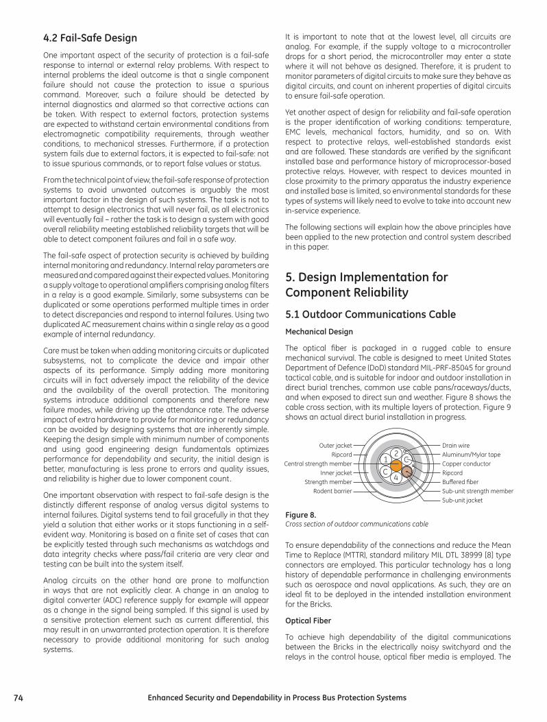
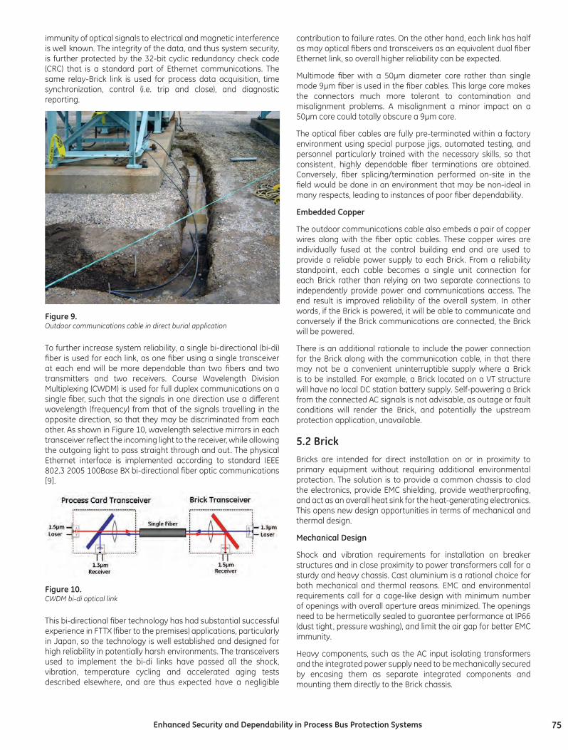
The optical fiber is packaged in a rugged cable to ensure mechanical survival. The cable is designed to meet United States Department of Defence (DoD) standard MIL-PRF-85045 for ground tactical cable, and is suitable for indoor and outdoor installation in direct burial trenches, common use cable pans/raceways/ducts, and when exposed to direct sun and weather. Figure 8 shows the cable cross section, with its multiple layers of protection. Figure 9 shows an actual direct burial installation in progress.
1 CC
2
4
Outer jacketRipcord
Central strength memberInner jacket
Strength memberRodent barrier
Drain wireAluminum/Mylar tapeCopper conductorRipcordBuffered fiberSub-unit strength memberSub-unit jacket
Figure 8.Cross section of outdoor communications cable
To ensure dependability of the connections and reduce the Mean Time to Replace (MTTR), standard military MIL DTL 38999 [8] type connectors are employed. This particular technology has a long history of dependable performance in challenging environments such as aerospace and naval applications. As such, they are an ideal fit to be deployed in the intended installation environment for the Bricks.
Optical Fiber
To achieve high dependability of the digital communications between the Bricks in the electrically noisy switchyard and the relays in the control house, optical fiber media is employed. The
75Enhanced Security and Dependability in Process Bus Protection Systems
immunity of optical signals to electrical and magnetic interference is well known. The integrity of the data, and thus system security, is further protected by the 32-bit cyclic redundancy check code (CRC) that is a standard part of Ethernet communications. The same relay-Brick link is used for process data acquisition, time synchronization, control (i.e. trip and close), and diagnostic reporting.
Figure 9.Outdoor communications cable in direct burial application
To further increase system reliability, a single bi-directional (bi-di) fiber is used for each link, as one fiber using a single transceiver at each end will be more dependable than two fibers and two transmitters and two receivers. Course Wavelength Division Multiplexing (CWDM) is used for full duplex communications on a single fiber, such that the signals in one direction use a different wavelength (frequency) from that of the signals travelling in the opposite direction, so that they may be discriminated from each other. As shown in Figure 10, wavelength selective mirrors in each transceiver reflect the incoming light to the receiver, while allowing the outgoing light to pass straight through and out. The physical Ethernet interface is implemented according to standard IEEE 802.3 2005 100Base BX bi-directional fiber optic communications [9].
Figure 10.CWDM bi-di optical link
This bi-directional fiber technology has had substantial successful experience in FTTX (fiber to the premises) applications, particularly in Japan, so the technology is well established and designed for high reliability in potentially harsh environments. The transceivers used to implement the bi-di links have passed all the shock, vibration, temperature cycling and accelerated aging tests described elsewhere, and are thus expected have a negligible
contribution to failure rates. On the other hand, each link has half as may optical fibers and transceivers as an equivalent dual fiber Ethernet link, so overall higher reliability can be expected.
Multimode fiber with a 50µm diameter core rather than single mode 9µm fiber is used in the fiber cables. This large core makes the connectors much more tolerant to contamination and misalignment problems. A misalignment a minor impact on a 50µm core could totally obscure a 9µm core.
The optical fiber cables are fully pre-terminated within a factory environment using special purpose jigs, automated testing, and personnel particularly trained with the necessary skills, so that consistent, highly dependable fiber terminations are obtained. Conversely, fiber splicing/termination performed on-site in the field would be done in an environment that may be non-ideal in many respects, leading to instances of poor fiber dependability.
Embedded Copper
The outdoor communications cable also embeds a pair of copper wires along with the fiber optic cables. These copper wires are individually fused at the control building end and are used to provide a reliable power supply to each Brick. From a reliability standpoint, each cable becomes a single unit connection for each Brick rather than relying on two separate connections to independently provide power and communications access. The end result is improved reliability of the overall system. In other words, if the Brick is powered, it will be able to communicate and conversely if the Brick communications are connected, the Brick will be powered.
There is an additional rationale to include the power connection for the Brick along with the communication cable, in that there may not be a convenient uninterruptible supply where a Brick is to be installed. For example, a Brick located on a VT structure will have no local DC station battery supply. Self-powering a Brick from the connected AC signals is not advisable, as outage or fault conditions will render the Brick, and potentially the upstream protection application, unavailable.
5.2 BrickBricks are intended for direct installation on or in proximity to primary equipment without requiring additional environmental protection. The solution is to provide a common chassis to clad the electronics, provide EMC shielding, provide weatherproofing, and act as an overall heat sink for the heat-generating electronics. This opens new design opportunities in terms of mechanical and thermal design.
Mechanical Design
Shock and vibration requirements for installation on breaker structures and in close proximity to power transformers call for a sturdy and heavy chassis. Cast aluminium is a rational choice for both mechanical and thermal reasons. EMC and environmental requirements call for a cage-like design with minimum number of openings with overall aperture areas minimized. The openings need to be hermetically sealed to guarantee performance at IP66 (dust tight, pressure washing), and limit the air gap for better EMC immunity.
Heavy components, such as the AC input isolating transformers and the integrated power supply need to be mechanically secured by encasing them as separate integrated components and mounting them directly to the Brick chassis.

76 Enhanced Security and Dependability in Process Bus Protection Systems
Thermal design considerations for critical heat-generating components are accounted for by mounting these components such that they use the chassis itself as a heat sink. At the same time, Bricks mounted outdoors are exposed to so-called insolation or “sunloading” effects – heating due to absorbed solar energy. This calls for striking a balance between the ability to transport the heat out of the chassis from the hot components inside, and minimizing the absorption of the radiated solar energy and heating effect on the components inside the chassis. A black matte finish maximizes heat radiation out of the Brick, but also maximizes absorption of solar radiation. A bright reflective finish minimizes absorption, but also minimizes radiation. This effect is not new and in fact standards such as IEC 60068-2-9 [10] and MIL-STD-810F [11] exist to address these issues. These standards call for over 1,000 W/m2 of solar radiation under an ambient air temperature of 50 degrees C. A relatively small amount of heat needs to be to dissipated, so a reflective finish is used. In order to ensure adequate sunload immunity under worst-case scenarios where the Brick chassis is dirty or otherwise non-reflective, solar testing was also performed with the specimen Brick painted matte black.
The Brick needs to be designed for both hot and cold temperatures. Under cold temperatures mechanical properties of fiber and cold temperature start-up sequencing of the electronics become a concern. Necessary design considerations include avoiding fiber connections by using pigtails embedded in transceivers, securing the fiber mechanically and testing under combined temperature and mechanical conditions.
The tests shown in Figures 11, 12 and 13 show environmental tests for dust ingress, water ingress and sunload effect.
Figure 11.Dust ingress testing for IP6x: pre-test (left) and post-test (right)
Figure 12.Water ingress testing for IPx6: pre-inspection (left) and post-inspection (right)
Figure 13.Solar loading tests at the solar laboratory: Bricks mounted next to light source (left), solar radiation test in progress (right)
Connectorized Interfaces
Terminations of the remote I/O device (Brick) are pre-connectorized using standard off-the-shelf MIL-DTL-38999 connectors. These connectors are available from multiple vendors and are used in naval, military, avionics and industrial applications because of their high performance and reliability including shock and vibration, IP rating, proper electrical parameters and extremes of temperature.
By selecting an extremely rugged and reliable connector technology, a number of design challenges for implementing reliable remote I/O devices are solved simply with a widely accepted hardware solution. The Mean Time to Replace (MTTR) is reduced by reducing Brick replacement time without the need to re-commission physical connections. Adoption of standard, reliable and proven connectors benefits from millions of unit years of field experience, lessons learned, independent verification tests and other aspects relevant to the overall reliability of the system.
An AC input connector brings the secondary currents into the Brick. A danger exists of opening the connector with the CTs live. Development of a self-shorting mechanism embedded in the connector would prevent the use of standard connectors, and would jeopardize reliability of the connector by adding moving parts. Following the principle of a simple design, the presented system uses a simple mechanical feature to prevent accidental disconnection of a live CT cable: the yellow collar shown in Figure 14 below. This is a good example of a design to avoid adverse impact on reliability of the system.
Figure 14.Safety device protecting against accidental opening of a live CT secondary circuit

77Enhanced Security and Dependability in Process Bus Protection Systems
Electronics
The Brick power supply is a good example of how a simple design can improve reliability by eliminating the need for electronics that have an adverse impact on reliability. A common source of failures in microprocessor relays is their power supply, in particular electrolytic capacitors used in the power supply to provide “hold-up” so a momentary interruption of the DC station battery does not force the relay to have to restart, a process that may take many seconds. Regardless of the grade of component selected (automotive, industrial), electrolytic capacitors have been repeatedly shown to be a reliability concern.
The simplicity of the Brick allows it to be fully functional within milliseconds of being energized as opposed to several seconds as with relays. By having the Brick start so quickly, the availability of protection from being momentarily powered down is virtually unchanged so there is no need to provide hold up in the power supply. This eliminates the electrolytic capacitors from the power supply, and reliability issues that they introduce.
Contact Inputs
The Brick contact inputs use dry contacts, with a 24 VDC sensing voltage provided by an internal isolated wetting supply generated by the Brick. The low wetting voltage allows a low sensing circuit impedance and a high wetting current. Low input impedance makes the Bricks highly immune to incorrect status indication due to induced transients or insulation degradation in the external contact wiring. High wetting current assists contact “wipe” action in obtaining a clean contact by burning off contact surface contamination. Having wetting supplies isolated independently for each Brick prevents station battery grounds and grounds in other Brick’s contact input circuits from causing incorrect status indication. The Brick contact input supplies are also designed so that two Bricks may be paralleled across a single dry contact, buffered such that the failure of one Brick will not adversely impact the operation of the remaining Brick.
Control Outputs
The Brick contains four solid-state relay (SSR) outputs, based on an existing highly tested and field-proven design, to directly interrupt typical breaker trip and close circuit currents. The SSR outputs were chosen with no moving parts so that mechanical
vibrations caused by a breaker mechanically operating could not cause a spurious or undesirable contact closure. The SSR outputs themselves are thermally bonded to the cast aluminium shell of the Brick, so the entire chassis acts as a heat sink improving the life expectation for the SSR outputs.
Analog Inputs
The self-testing involved with AC and transducer inputs is worth further discussion.
Two ADCs are employed on each AC input, as shown in Figure 15. The input to the high range ADC is scaled to accept high currents without saturating. The input to the low range ADC is scaled for accuracy at low currents, but clips for currents much above nominal. At each sample instant, the programmable logic device (PLD) starts a conversion on both ADCs, and coordinates sending both conversion results to the digital cores. Microcontrollers in the digital cores use the low range ADC value if not saturated, otherwise they use the high range ADC value. Part of the reason this is done is that available monolithic analog to digital converters (ADCs) with sufficient speed to sample at the rates demanded by today’s relays cannot provide the necessary metering accuracy without saturating at high fault currents.
The other reason for dual ADCs on each input is that it provides a unique opportunity for continuous self-testing of the AC input hardware.
Phase CT current inputs are at most times at a level where the waveforms are continuously in the low range. However, except near zero crossings the high level ADC retains sufficient accuracy that there ought to be no significant difference between the high and low range values after accounting for the design scaling differences. Any significant difference indicates a failure in one range or the other. The comparison is made on a sample-by-sample basis, so protection can be disabled before the invalid data is consumed. Disabling protection on detection of invalid AC input data is an immediate security benefit. It also has a positive impact on dependability, as it alarms triggering rapid corrective action.
In addition to dual ADCs, dual anti-alias filters and dual input conditioning and gain stages are provided so that problems in these areas are also detected by the same comparison. The
x1 LPF 16-bitADC
16-bitADC
LPF PLD
digitalcore
Anti-alias filter
Anti-alias filter
Low Range Channel
High Range Channel
digitalcore
digitalcore
digitalcore
xK+
_
Figure 15.Typical Brick AC input hardware block diagram

78 Enhanced Security and Dependability in Process Bus Protection Systems
low range uses the entire secondary winding of the isolating transformer, while the high range uses only half of the secondary. Thus any trouble in the isolating transformer secondary will be detected as well. The comparison is made in the digital cores, providing detection of troubles getting the data through the PLD and into the microcontrollers. Thus the entire AC input hardware circuit is covered, with the exception of the isolating transformer primary, which for CT inputs consists simply of either one or five turns of heavy gauge wire.
Figure 16 illustrates the comparison process. The low (blue) and high (red) range scaled readings are shown in the top graph; the selected signal in the middle graph, and the error flag in the bottom graph, for the case of a 1.2 times nominal current experiencing a negative 20% error in the high range channel.
Figure 16.Simulation of a high range gain error on a CT input
When the input signal is so high that the low range clips the peaks, as happens with normal values of VT inputs and on CT inputs during faults, the comparison can still be made in the vicinity of zero crossings. Figure 17 shows a case of a 70V voltage losing reference in the high range channel. The trouble is detected, but after a short delay of up to ½ cycle.
Figure 17.Simulation of a loss of high range reference supply on a CT input
5.3 RelayIn the presented system, the relay (IED) portion transforms from a mixed analog and digital device to an almost exclusively digital device as all analog inputs and outputs are eliminated and replaced with digital communications. As a result, the relay portion of the system becomes much more reliable and intrinsically fail-safe. The reliability gain is achieved by reducing the individual part counts, and by using digital components that tend to be more reliable due to their highly integrated packaging and pre-determined failure mechanisms. The fail-safe improvement is caused by the nature of digital systems as explained in the previous section. The input and output signals are moved between different digital subsystems of the relay (receiving transceivers, communication processor, digital signal processors, main logic processor) as digital packages with embedded data integrity protection (CRC, check-sum). All digital components are properly engineered (monitored rails, watchdog, code integrity checks, etc.) yielding a very robust system.
Communication-based protection and control systems require more design attention in terms of dealing with permutations of various conditions related to distributed architectures, multiple devices and communication traffic and impairments. Development of distributed architectures is not a new enterprise - there is a great deal of experience accumulated from engineering internal architectures of modular relays and engineering and application of digital line current differential or distributed bus differential relays.
In the case of the particular design presented in this paper, the relays are built using an existing relay platform with a decade-long field record, the maturity of a large portion of hardware and firmware being carried over to the new system. This modular relay series uses just one new hardware module to interface with the remote I/O (Bricks) and keeps the existing power supply, CPU and teleprotection modules intact. Even the existing firmware is used – the I/O data are seamlessly integrated with the rest of the relay.
In this way some 80% of the relay hardware is not changed, and some 95% of the relay firmware is not changed. Moreover, the new relay is not a new model or variant of the existing relay, but an option on the existing platform. In this way even the impact of regression during development of the code has been drastically reduced as only a small amount of new code was added to the existing proven relay firmware.
In this way a significant portion of the field experience in terms of hundreds of thousands of unit years of run time, independent testing of hardware and algorithms, and exposure to actual system conditions can be instantly assigned to the relay and application portion of the new protection and control system.
5.4 Extensive self-testingThe described protection system implements extensive self-testing in order to reduce the repair response delay thus increasing availability and dependability, and to flag unreliable data so that it is not used to make operational decisions thus increasing protection system security. It is critical that internal self-monitoring within the system overlaps adequately to ensure complete end-to-end self-testing. The concept of overlapping test zones is shown in Figure 18.
It can be seen that there are a number of self-test zones within the system, each individual self-test zone overlaps with at least one other zone.

79Enhanced Security and Dependability in Process Bus Protection Systems
Comm
on I/O H
ardware
Process Bus Interface
CPU
Hardw
are Buffering
DigitalCore
DigitalCore
DigitalCore
DigitalCore
Remote I/O (Brick) RelayFiberComms
Digital SystemsAnalogueSystems
Figure 18.Overlapping test zones within the system
The specific self-tests within the Brick include the following:
• On each AC and each transducer/RTD input, correspondence of the high range analog to digital converter output with that of the low range analog to digital converter.
• Proper sequencing of the analog to digital converters through monitoring of their Busy status output.
• Temperature of the analog to digital converter.
• Output levels of each of the internal power supplies.
• Watchdog timers, one external to each microcontroller, which together with firmware in the microcontroller verifies all tasks are running as designed.
• Microcontroller flash memory integrity through CRC-16 checking.
• Communications between the analog core and each digital core in each direction are uninterrupted and each frame’s CRC-16 shows data is uncorrupted.
• Match in clock frequencies between the analog core clock and each digital core clock.
• Correspondence of each contact output driver to the received command for that contact.
• Correspondence of an auxiliary contact on the latching output relay to the latching output command.
• Monitoring of the voltage across and current through each SSR contact output, used by the relay to monitor the health of the external control circuit.
The tests of the fiber optic communications include:
• Signal quality of each of the optical fiber links, including the send and receive optical light levels at each end, transmitter bias current, and transceiver temperature.
• Integrity of each frame sent and received on the optical fiber links through CRC-32 checking, lost frames are detected with sequence numbers.
The relay itself also runs a complete set of internal self-tests as per established relay design philosophy, including processor watchdogs, program execution and internal data integrity checks.
Also, it is important to note the dividing line between analog and digital systems. The amount of the system that is based on analog circuitry is limited to the interface to the primary power system process. The rest of the system is entirely digital, allowing for this high degree of built-in error checking and diagnostics.
5.5 Continuous MonitoringIn order to ensure the security of protection, each Brick core continuously monitors its key internal subsystems including the common hardware (ADCs, output relay circuits) and the status of the core itself. Each core includes this diagnostic information with each set of samples transmitted to the connected relay. In the event of a failure of an internal diagnostic test, the connected relays are made aware instantly and can then ensure that the overall protection system will fail to a safe state.
Additionally, each core continuously monitors the optical transmit and receive power from the associated transceiver and sends this data to the connected relay. Each transceiver in the relay measures the same quantity and then calculates the respective power link budget for the connection. In this case, troubles related to the degradation of the optical communications path can be determined early and explicitly.
5.6 Duplicated I/O HardwareThe protection system presented in this paper provides the user with the ability to control the dependability and security of the system by supporting duplicate Bricks (the remote I/O modules), as illustrated in Figure 5. The primary sensors for signals critical to system reliability can also be duplicated, the signals transmitted thought independent Bricks and independent optical fibers to the relay, where a variety of options exists for reacting to loss of communications with the Bricks, Brick self-test error conditions, and inconsistency of the received values. The status inputs and control outputs may also be provisioned to provide a high degree of dependability or security.
Data Crosschecking
For instance, it is possible where CT reliability is of special concern, to use two independent CT cores per phase, one to the CT inputs of each of two duplicated Bricks. Alternatively, a single CT core can drive both Bricks. The elimination of long runs of CT wiring back to the control house results in virtually zero external burden on the CT, reducing voltage stress on the CT secondary, and thus increasing the already high CT reliability. This of course also decreases the CTs propensity to flux saturation. Each of the two Bricks independently samples its input CT signal, converts the samples to digital form, and sends the digital samples back to the relay over independent optical fibers.
VT inputs are handled in the same fashion, so the term AC input is used here to indicate either a CT or VT input.
At the relay, user settings control how the two streams of samples from the two AC inputs are combined into a virtual AC bank, which

80 Enhanced Security and Dependability in Process Bus Protection Systems
is used by the relay’s internal functions operating on that CT/VT signal. Each AC bank has two settings that select the three-phase Brick AC inputs used for that bank. The Origin 1 setting selects the primary source for AC inputs that are to be used provided that the corresponding Brick is enabled, communications with the Brick are intact and correct, and the Brick reports no internal self-tests errors. The Origin 2 setting selects the AC inputs that are to be used when Origin 2 AC inputs are available and Origin 1 AC inputs are not available. If neither is available, the AC bank samples are forced to zero, as this corresponds to the normal failsafe state in traditional protection and control.
This simple auto-transfer scheme is illustrated in Figure 19, where the top group of traces are the samples from origin 1, the next group are from origin 2, and the bottom group are that of the AC bank. It is important to note that the AC bank is unaffected by all except the loss of both origins.
Figure 19.Oscillography illustrating seamless auto-transfer on Brick trouble
To allow user control of the dependability/security trade-off when duplicated Bricks are provided, an AC bank crosschecking setting is available. This setting allows the user to enable comparison of the samples from the two origins, and to control the behavior of the protection elements in the event that the relay detects one of the two origins is unavailable.
When enabled, the discrepancy detection algorithm compares each sample from the two duplicated sets. If the two sets of samples are available, and are substantially different without clear declaration of a Brick self-test error, execution of the relay protection elements is suspended, as at least one set of samples is incorrect and the relay is unable to explicitly determine the valid source with which to continue operation. Note that due to the extensive self-checking, in virtually 100% of cases of HardFiber equipment failure, the relay is able to determine the invalid source, and thus can continue to operate using the other source. It is only when it is unable to determine this that operation need be suspended.
In applications where the duplicated CT inputs are from different CT cores, there is the possibility that under fault conditions
the output of the two CT cores may differ to some degree due to manufacturing tolerances or unequal burdens. To prevent unwarranted discrepancy declarations, a restraint characteristic is applied under normal (i.e. load) conditions, and discrepancy checking is suspended when currents are much greater than the CT nominal rating. The discrepancy checking algorithm characteristic is illustrated in Figure 20. The feature of suspending discrepancy check is not applied for VT inputs, but for CT inputs only.
FreezeDiscrepancy
Detection
DeclareDiscrepancy
DeclareDiscrepancy
FreezeDiscrepancy
Detection
FreezeDiscrepancy
Detection
FreezeDiscrepancy
Detection
X2
A3
A1
A2
A2
A2
A2
-A3
-A1
-A1
A1 A3-A3 X1
Expecte
d Values
Expecte
d Values
Figure 20.X1 and X2 are the sample values from origin 1 and origin 2 respectively.A1, A2 and A3 are parameters, values here exaggerated for clarity.
The discrepancy check algorithm can be enabled in one of two modes: Dependability Biased, or Security Biased. These differ in the reaction of the relay to the unavailability of just one of the duplicated Bricks.
In the Security Biased mode, protection will function only if both duplicate Bricks are available and both sets of samples are in agreement. The Security Biased mode is used in applications where the probability of a fault is relatively low and the system impact is very large, so it is important that protection not operate incorrectly due to AC measurement error – in other words it is justified to require two independent measurements be in agreement to operate.
In the Dependability Biased mode, discrepancy checking is only performed when sets of samples from both duplicate Bricks are available. The discrepancy check is therefore declared and protection blocked only if both Bricks are available and the sets of samples are substantially different. The clear unavailability of a single Brick (loss of communications, internal self-test failure) does not block protection. The Dependability Biased mode is used in applications where the probability of fault occurrence is higher and the system impact is lower, or in instances where a failure to trip may result in unacceptable damage to a major power system element like a generator. It is important therefore that protection is highly available – in other words it is more desirable to allow protection to continue to operate without two independent measurements.

81Enhanced Security and Dependability in Process Bus Protection Systems
It is also possible to use duplicated Bricks without running the discrepancy checking. By not choosing either the Dependability or Security Biased mode, the relay will use the samples from origin 1 exclusively. In the event that the origin 1 Brick becomes clearly unavailable, the relay will simply switch to using the origin 2 samples.
Origin 1 status
Origin 2 status
Discrepancy check
Crosschecking setting
Dependability biased
Security biased None
Available Available OK Protection available
Protection available
Protection available
Available Available Discrepant Protection suspended
Protection suspended
Protection available
Unavailable Available Not relevant Protection available
Protection suspended
Protection available
Available Unavailable Not relevant Protection available
Protection suspended
Protection available
Unavailable Unavailable Not relevant Protection suspended
Protection suspended
Protection suspended
Table 1. Effect of dependability biased/security biased setting on duplicated Bricks
The effects of Dependability Biased verses Security Biased crosschecking modes are illustrated in Figure 21. In both graphs, the top two groups of traces are the samples from the two Bricks, the next group is the samples from the AC bank, and the bottom two traces are the pickup of an instantaneous and a timed overcurrent protection element respectively. In each graph, the origin 1 Brick samples become discrepant shortly after the start of a simulated fault.
Figure 21.Oscillography illustrating effect of (a) dependability biased vs. (b) security biased modes
The Dependability Biased mode is shown in the top graph (a), so the instantaneous protection and the timed protection picks up on
the origin 1 samples, then timed protection times out on origin 2 samples; protection operation is dependable in spite of the Brick failure. The Security Biased mode was used for the bottom graph (b), so the instantaneous protection picks up as above, but then protection is suspended when the Brick fails, halting timeout of the timed protection, thus securing the protection.
Although in this particular case it is clear from the traces that the discrepancy was most likely in the origin 1 samples so the auto-transfer to origin 2 and subsequent tripping was the correct decision, in other cases the choice might not be so clear even to an experienced engineer looking at the post-mortem data, and especially difficult for a relay in a real-time operation.
Note that discrepancy checking is only done when both samples are received, and neither of the Bricks involved indicate any self-test error that calls into question the validity of its AC input data. The Brick self-tests are intended to detect internal Brick troubles that could corrupt AC input data, and so two available samples should only be found discrepant when the Bricks are otherwise functioning normally. Thus assuming failure independence, in the Dependability Biased mode, the unavailability of protection approaches the square of the unavailability of a single Brick. In the Security Biased mode, the availability of protection approaches the square of the availability of a single Brick.
Duplicate Input/Output Hardware
In addition to supporting duplication of AC inputs, the described system also supports duplicated contact inputs and outputs. As there are many different schemes to make use of duplicated contacts, user programmable logic is used.
Redundancy schemes for contact inputs include:
• OR the two contact inputs – dependable
• AND the two contact inputs – secure
• AND a form A contact input with the inverse of a form B contact input
• Main/backup contact inputs
• Instantaneous on both contact inputs closed, delayed on single contact input closed
• Last state where both contact inputs agreed
• Two of three, majority logic
Implementation logic for a main/backup scheme is shown in Figure 22. Here a main and a backup contact of a transformer gas relay are connected to main and backup Bricks. The protection (not shown) uses the main contact input provided it is available (Main Brick On), otherwise uses the backup contact. The scheme annunciates trouble should the main and backup states be available and discrepant. The alarm is delayed by 4.0ms to allow for unequal sensor contact operating times, yet still ensure alarming for discrepant operations.
Redundancy schemes for contact outputs include:
• Two output contacts in parallel - dependable
• Two output contacts in series - secure
• Four output contacts in “H” configuration – dependable and secure

82 Enhanced Security and Dependability in Process Bus Protection Systems
One example of the H configuration is shown in Figure 23. This arrangement is dependable in that it will continue to operate should either Brick fail or any single contact output fail open. It is secure in that it will not operate should any single contact output fail short.
Brick 1/OUT1 Brick 2/OUT2
Brick 2/OUT1 Brick 1/OUT2
“H” Configuration
Figure 23.Highly dependable and secure contact output scheme
6. ConclusionThis paper outlined the high-level design principles for protection and control systems. These principles are illustrated using a new practical solution for implementing ultra-critical protection and control IEC 61850 process bus applications. Several applications of these principles are explained. Moreover, the system allows eliminating significant amount of labour and therefore reduces costs and shortens the required deployment time.
A significant amount of detail is given regarding the design of this new solution as related to security and dependability. Special attention has been paid to the fail-safe aspect of the design. By relying more on digital interfaces and subsystems, the system is made more fail-safe: it either works or it stops functioning in a self-evident way, with a greatly reduced probability of a subsystem being in a faulted yet undetected state.
The system also supports the use of duplicated I/O devices for protection applications to achieve a high degree of reliability, and supports applications requirements for dependability or security improved over existing protection technology. The remote I/O devices are shared between multiple relays and therefore the solution is not cost-prohibitive compared to providing multiple independent remote I/O devices for each relay.
It can be demonstrated that the system is more reliable, dependable and secure when compared with existing solutions. The following key elements contribute to the enhancements.
• The total amount of hardware in the system is less compared with traditional solutions. This is due to the shared I/O devices. Systems with fewer components are generally more reliable.
• The I/O devices themselves incorporate a substantial amount of self-monitoring to detect internal problems.
• Duplicated I/O devices are used with constant crosschecking of input data, while supporting the use of inputs and outputs in redundant applications. The principle of duplication can be extended to instrument transformers providing for an extra layer of redundancy within each of the protection systems.
• Data is moved digitally secured with data integrity mechanisms. Digital systems are continuously monitored and will fail in predictable ways and self demonstrating ways compared with analog subsystems.
Figure 22.Main/backup contact input redundancy scheme

83Enhanced Security and Dependability in Process Bus Protection Systems
062609-v2
• The continuous internal self-testing, crosschecking and data integrity mechanisms will detect problems instantly allowing the field crews to rectify the problem quickly and precisely. This eliminates a considerable number of failures that may remain latent in traditional protection systems as well as failures that require a great deal of labour effort to diagnose and repair (for example DC battery grounds).
• The proposed system is easily testable and maintainable [12]. The physical provisioning of communication links using fiber patch cords provides a clear maintenance boundary that does not require relay maintenance personnel to deal with potentially lethal high-energy signals.
• The continuous monitoring of the digital communications links and the overall architecture greatly reduces the potential for human errors to result in undesired protection operations during testing and maintenance activities.
• The system is free from cyber-security concerns. The point-to-point, non-routable process bus network makes it inherently secure with no need for external monitoring mechanisms that would otherwise create extra cost and complexity and expose the system to external threats.
Also, the presented system is composed of only few highly connectorized standard devices in a modular, scalable architecture. This makes the solution very attractive from the point of view of initial installation as well as repair and/or reconstruction in the event of a catastrophic event such as a natural disaster.
The presented system allows protection relays to be made internally redundant and safe, making it very attractive in traditional as well as ultra-critical applications including nuclear power plants, and naval installations.
• Observing the data received by the relay over the link is reasonable and matches other indicators. For example indicated current/voltage magnitude and phase matches other indicators of these same quantities.
• Causing some change of state and observing its correct communication over the link. For example, observe the reported effects of initiating a breaker operation or a tap change. Initiation may be from the operator’s HMI where it uses the same fiber link.
• The relays are designed such that when normally in-service, they alarm and reject data on a port when the HardFiber Brick serial number that is included with the data fails to match the relay setting for that HardFiber Brick’s serial number. The relay serial number value is included with outgoing commands, and the HardFiber Bricks are designed to accept commands only when the accompanying serial number matches its own serial number. Thus, once the HardFiber Brick serial numbers are correctly entered into the relay settings, the fact of normal communications establishes that the link is correct. The serial number setting in the relay can be manually checked against the serial number on the HardFiber Brick’s nameplate.
Thus it can be seen that testing of the passive interconnection system is quite simple, and that after commissioning is complete, it can be entirely automatic.
7. References [1] IEC International Standard “Communication networks and
systems in substations - Part 9-2: Specific Communication Service Mapping (SCSM) – Sampled values over ISO/IEC 8802-3”, (IEC Reference number IEC/TR 61850-9-2:2004(E), IEC, Geneva, Switzerland).
[2] HardFiber Process Bus System Reference Manual, GE Publication GEK-113500.
[3] Northeast Power Coordinating Council, “Bulk Power System Protection Criteria”, Revised January 30, 2006
[4] FRCC System Disturbance and Underfrequency Load Shedding Event Report February 26th, 2008 at 1:09 pm Final Report Issued by: FRCC Event Analysis Team October 30, 2008 https://www.frcc.com/OC/Shared%20Documents/FEAT%20Report%20-%20Final.pdf
[5] B. Kasztenny, J. Whatley, E. A. Udren, J. Burger, D. Finney, M. Adamiak, “Unanswered Questions about IEC 61850: What needs to happen to realize the vision?” (Proceedings of the 32nd Annual Western Protective Relay Conference, Spokane, WA, October 25-27, 2005)
[6] B. Kasztenny, D. McGinn, S. Hodder, D. Ma, J. Mazereeuw, M. Goraj, “A Practical IEC61850-9-2 Process Bus Architecture Driven by Topology of the Primary Equipment” (42 CIGRE Session, Paris, August 24-29, 2008, paper B5-105).
[7] M. Adamiak, B. Kasztenny, J. Mazereeuw, D. McGinn, S. Hodder “Considerations for Process Bus deployment in real-world protection and control systems: a business analysis” (42 CIGRE Session, Paris, August 24-29, 2008, paper B5-102).
[8] Detail Specification MIL-DTL-38999L “Connectors, Electrical, Circular, Miniature, High Density, Quick Disconnect (Bayonet, Threaded, and Breech Coupling), Environment Resistant, Removable Crimp and Hermetic Solder Contacts, General Specification for”, United States of America Department of Defense, 30 May 2008.
[9] “IEEE Standard for Information technology— Telecommunications and information exchange between systems— Local and metropolitan area networks—Specific requirements Part 3: Carrier sense multiple access with collision detection (CSMA/CD) access method and physical layer specifications” IEEE Std 802.3™-2005, clause “58. Physical Medium Dependent (PMD) sublayer and medium, type 100BASE-LX10 (Long Wavelength) and 100BASE-BX10 (BiDirectional Long Wavelength)”
[10] IEC International Standard “Environmental testing - Part 2: Tests. Guidance for solar radiation testing”, (IEC Reference number IEC 60068-2-9:1975, IEC, Geneva, Switzerland).
[11] Test Method Standard MIL-STD-810F “Department of Defense Test Method Standard for Environmental Engineering Considerations and Laboratory Tests”, United States of America Department of Defense, 1 January 2000.
[12] D. McGinn, S. Hodder, B. Kasztenny, D. Ma “Constraints and Solutions in Testing IEC 61850 Process Bus Protection and Control Systems” (42 CIGRE Session, Paris, August 24-29, 2008, paper B5-206).