Enhanced Culvert Inspections Best Practices Guidebook
125
Minnesota Department of Transportaon Research Services & Library 395 John Ireland Boulevard, MS 330 St. Paul, Minnesota 55155-1899 (651) 366-3780 Guidebook ENHANCED CULVERT INSPECTIONS BEST PRACTICES Author: Doug Youngblood, CDM Smith Report Number: 2017-16 Date Published: June 2017
Transcript of Enhanced Culvert Inspections Best Practices Guidebook

Minnesota Department of Transportation Research Services & Library
395 John Ireland Boulevard, MS 330 St. Paul, Minnesota 55155-1899
(651) 366-3780
GuidebookE N H A N C E D C U L V E R T I N S P E C T I O N S B E S T P R A C T I C E S
Author: Doug Youngblood, CDM Smith Report Number: 2017-16 Date Published: June 2017
Technical Report Documentation Page
1. Report No. 2. 3. Recipients Accession No.
MN/RC 2017-16
4. Title and Subtitle 5. Report Date
Enhanced Culvert Inspections – Best Practices Guidebook June 2017
6.
7. Author(s)
Doug Youngblood8. Performing Organization Report No.
9. Performing Organization Name and Address 10. Project/Task/Work Unit No.
CDM Smith7650 Currell Blvd, Suite 300Woodbury, MN 55125
11. Contract (C) or Grant (G) No.
1002140
12. Sponsoring Organization Name and Address 13. Type of Report and Period Covered
Minnesota Department of TransportationResearch Services & Library395 John Ireland Boulevard, MS 330St. Paul, Minnesota 55155-1899
Final Report
14. Sponsoring Agency Code
15. Supplementary Notes
http:// mndot.gov/research/reports/2017/201716.pdf
16. Abstract (Limit: 250 words)
Culvert inspection is a key enabler that allows MnDOT to manage the state’s highway culvert system. Whenquantitative detail on culvert condition is required, an inspector will need to use enhanced inspection technologies.Enhanced inspection technologies such as; laser ring profiling, sonar, inclinometer, mandrel, hammer sound testing,core sampling, closed circuit television (CCTV), HIVE and JPEG mosaic testing, can measure or digitally record conditionthat would not be apparent from a simple visual inspection. In general, MnDOT should balance the higher cost ofconducting an enhanced inspection against the quality of data needed. It is estimated that simple end-of-pipe visualinspection costs $0.07/ft. Enhanced inspections range from $0.23/ft to $6.50/ft with higher cost inspections providingmore detailed data. Estimates are developed using year 2016 unit costs. Best practices for each type of inspection areidentified and presented in this guidance document. In addition, practical and logistic considerations are identified toassist staff in selecting cost-effective inspection methods for typical types of inspection. Types of inspection include:design-related, post-construction, condition and emergency / complaint-related inspection. Recommendations arepresented to improve MnDOT’s enhanced inspection program. Recommendations include leveraging MnDOT’s laserring inspection unit and increasing the use of MnDOT-developed HIVE cameras.
17. Document Analysis/Descriptors 18. Availability Statement
closed circuit television, culverts, inspection, scanners, lasers,
hammers, quality control
No restrictions. Document available from:
National Technical Information Services,
Alexandria, Virginia 22312
19. Security Class (this report) 20. Security Class (this page) 21. No. of Pages 22. Price
Unclassified Unclassified 125
Enhanced Culvert Inspections Best Practices Handbook
FINAL REPORT
Prepared by:
Doug YoungbloodCDM Smith
June 2017
Published by:
Minnesota Department of Transportation Research Services & Library 395 John Ireland Boulevard, MS 330 St. Paul, Minnesota 55155-1899
This report represents the results of research conducted by the authors and does not necessarily represent the views or policies of the Minnesota Department of Transportation or CDM Smith. This report does not contain a standard or specified technique.
The authors, the Minnesota Department of Transportation, and CDM Smith do not endorse products or manufacturers. Trade or manufacturers’ names appear herein solely because they are considered essential to this report because they are considered essential to this report.
To request this document in an alternative format, such as braille or large print, call 651-366-4718 or 1- 800-657-3774 (Greater Minnesota) or email your request to [email protected]. Please request at least one week in advance.

Acknowledgements
The author wishes to thank the following members of the Technical Advisory Panel who provided valuable information in the development or revision of this guide.
• Andrea Hendrickson, MnDOT Office of Bridges/Hydraulics Section (Technical Liaison)• Kevin Kosobud, MnDOT Office of Construction and Innovative Contracting• Bonnie Peterson, MnDOT Office of Bridges/Hydraulics Section• Anton Audette, MnDOT Metro District/Oakdale Sub-Area• Michael Juen, MnDOT Metro District/Oakdale Sub-Area• Kristoffer Langlie, MnDOT District 6/Design• Shanna Kent, MnDOT District 8/Hutchinson Construction• Lee Daleiden , MnDOT Metro District/Water Resources• Tom Krier, MnDOT Metro District/Northeast Resident Office• Bruce Holdhusen, MnDOT Research Services and Library
TABLE OF CONTENTS
CHAPTER 1: Introduction ....................................................................................................................1 1.1 Development of Best Practices........................................................................................................... 2
1.1.1 Interviews .................................................................................................................................... 2 1.1.2 Literature Review ........................................................................................................................ 2 1.1.3 Review of Existing Video ............................................................................................................. 2 1.1.4 Field Inspections .......................................................................................................................... 2
1.2 Enhanced Inspection Definitions and Objectives ............................................................................... 3 1.2.1 Definitions ................................................................................................................................... 3 1.2.2 Abbreviations .............................................................................................................................. 4 1.2.3 Types of Culvert Inspection ......................................................................................................... 5
1.3 Limitations of Guidance Document and Staff Judgment .................................................................... 6 CHAPTER 2: Objectives and Technology Selection ...............................................................................7
2.1 Culvert Inspection Objectives ............................................................................................................. 7 2.2 Inspection Frequency and Benchmarking .......................................................................................... 7
2.2.1 Post-Construction Inspection ...................................................................................................... 7 2.2.2 Condition Inspection Frequency ................................................................................................. 7 2.2.3 Design Inspection Frequency ...................................................................................................... 8
CHAPTER 3: Technology .....................................................................................................................9 3.1 Summary of Inspection Approaches ................................................................................................... 9
3.1.1 End-of-Pipe Inspection ................................................................................................................ 9 3.1.2 Measurement-Based Inspection ............................................................................................... 12 3.1.3 Mandrel Inspection Technology ................................................................................................ 16 3.1.4 Hammer Sound Testing (Person Entry-Facilitated Inspection) ................................................. 18 3.1.5 Core Sampling Test (Person Entry Facilitated Inspection) ........................................................ 21 3.1.6 Closed Circuit Television Camera Inspection ............................................................................ 22
3.2 Innovative or Emerging Technologies .............................................................................................. 25 3.2.1 HIVE Inspection ......................................................................................................................... 25 3.2.2 JPEG Mosaic Inspection ............................................................................................................. 27
CHAPTER 4: Enhanced Inspection Technology Selection .................................................................... 30 4.1 Selection by Inspection Type ............................................................................................................ 30 4.2 Selection by Suspected Damage ....................................................................................................... 32
CHAPTER 5: Best Practices ................................................................................................................ 38 5.1 Planning Phase .................................................................................................................................. 38
5.1.1 Review of Existing Data ............................................................................................................. 38 5.1.2 Preliminary Site Inspection ........................................................................................................ 38 5.1.3 Define Inspection Scope ............................................................................................................ 39 5.1.4 Procure Inspection Services ...................................................................................................... 39 5.1.5 Complete Pre-Inspection Work ................................................................................................. 39 5.1.6 Conduct Pre-Inspection Checks on Inspection Equipment ....................................................... 40
5.2 Implementation Phase ..................................................................................................................... 40 5.2.1 End-of-Pipe Inspection without Person Entry Procedure ......................................................... 41 5.2.2 Multiple Sensor Inspection Procedure ...................................................................................... 41 5.2.3 Mandrel Inspection Procedure .................................................................................................. 41 5.2.4 Hammer Sound Testing Procedure (Person Entry Facilitated) .................................................. 42 5.2.5 Core Sampling Concrete Culverts Procedure (Person Entry Facilitated) .................................. 42
5.2.6 Closed Circuit Television Inspection Procedure ........................................................................ 43 5.2.7 HIVE Inspection Procedure ........................................................................................................ 44 5.2.8 JPEG Mosaic Inspection Procedure ........................................................................................... 44
5.3 Data Evaluation Phase ...................................................................................................................... 44 5.3.1 Conduct Data Quality Control Reviews ..................................................................................... 45 5.3.2 CCTV and HIVE Inspection Video Quality Control Parameters .................................................. 46 5.3.3 Data Evaluation ......................................................................................................................... 48
5.4 Project Closeout Phase ..................................................................................................................... 49 5.4.1 Closeout Contract ...................................................................................................................... 50 5.4.2 Archive Data .............................................................................................................................. 50
CHAPTER 6: Cost-Effectiveness of Enhanced Inspection ..................................................................... 51 6.1 Risk Avoidance .................................................................................................................................. 51 6.2 Cost-Effectiveness Considerations for Design-Related Inspections ................................................. 51 6.3 Cost-Effectiveness Considerations for Post-Construction Acceptance Inspection .......................... 52
6.3.1 End-of-Pipe vs. CCTV Inspection for Post-Construction Acceptance ........................................ 52 6.3.2 End-of-Pipe vs. CCTV Inspection for CIPP Lining Acceptance .................................................... 53 6.3.3 Mandrel vs. Laser Scan Inspection for Post-Construction Deflection Testing of Plastic Culverts ............................................................................................................................................................ 53
6.4 Cost-Effectiveness Considerations for Condition Inspection ........................................................... 54 6.4.1 End-of-Pipe vs. HIVE Camera vs. CCTV Camera Inspection for HydInfra Inspections ............... 54 6.4.2 Laser Scan Inspection for HydInfra Inspections ........................................................................ 55 6.4.3 Optimal Uses for Sonar, Hammer Sound Testing, and Core Testing ......................................... 55
6.5 Cost-Effectiveness Considerations for Emergency/Complaint-Related Inspection ......................... 56 CHAPTER 7: Conclusions and Next Steps ........................................................................................... 57
7.1 Conclusions from Field Inspections .................................................................................................. 57 7.2 Next Steps ......................................................................................................................................... 57
References ....................................................................................................................................... 59 Appendix A State of the Industry Interview Summary Appendix B Summary of Related LIterature Appendix C Review of Sample Inspection Video Appendix D Summary of Field Inspections Appendix E Guide Specifications
LIST OF FIGURES
Figure 1.1 – Unseen Culvert Damage ............................................................................................................ 1 Figure 1.2 – Video Inspection Video Snapshot ............................................................................................. 2 Figure 1.3 – Example Output from a Laser Scan Inspection ......................................................................... 3 Figure 1.4 – Inspections Expected over the Lifecycle of a Culvert ................................................................ 5 Figure 3.1 – Wire Mesh Model Generated from Laser Scan Inspection Data .............................................. 9 Figure 3.2 – Person Entry Inspection of a Rectangular Culvert .................................................................... 9 Figure 3.3 – Multiple Inspection Unit ......................................................................................................... 12 Figure 3.4 – Laser Ring Scanner .................................................................................................................. 13 Figure 3.5 – Hammer Sound Testing ........................................................................................................... 20 Figure 3.6 – Image Capture from CCTV Camera Inspection ....................................................................... 22 Figure 3.7 – HIVE Camera Unit .................................................................................................................... 25

Figure 3.8 – Image Capture from a HIVE Camera ....................................................................................... 27 Figure 3.9 – Output from a JPEG Mosaic Inspection .................................................................................. 27 Figure 4.1 – Inspection Technologies Based on Data Needs ...................................................................... 31 Figure 5.1 – HydInfra Software Interface .................................................................................................... 38 Figure 5.2 – Ovality Measurement from Laser Ring Scan Software ........................................................... 41 Figure 5.3 – Hammer Sound Testing ........................................................................................................... 42 Figure 5.4 – Footage Counter on a CCTV Camera Screen ........................................................................... 43 Figure 5.5 – CCTV Image with Too Much Light ........................................................................................... 46 Figure 5.6 – CCTV Image Distortion ............................................................................................................ 47 Figure 5.7 – Video Inspection of a Cured-in-Place Pipe Liner ..................................................................... 49 Figure 7.1 – MnDOT’s Teledyne Blueview BV1350 Sonar Scanner ............................................................. 58
LIST OF TABLES
Table 3.1 – End-of-Pipe Inspection Considerations .................................................................................... 10 Table 3.2 – Multiple Sensor Inspection Considerations.............................................................................. 13 Table 3.3 – Mandrel Inspection Considerations ......................................................................................... 16 Table 3.4 – Hammer Sound Testing Considerations ................................................................................... 19 Table 3.5 – Core Sample Testing Considerations ........................................................................................ 21 Table 3.6 – CCTV Camera Inspection Considerations ................................................................................. 23 Table 3.7 – HIVE Inspection Considerations ............................................................................................... 25 Table 3.8 – JPEG Mosaic Inspection Considerations ................................................................................... 28 Table 4.1 – Applicable Technologies by Inspection Type ........................................................................... 30 Table 4.2 – Applicable Inspection Technologies to Identify and Measure Common Types of Culvert Damage ....................................................................................................................................................... 33 Table 5.1 – Quality Control Considerations for Enhanced Inspection ........................................................ 45

ES-1
EXECUTIVE SUMMARY
The Minnesota Department of Transportation (MnDOT) is responsible for the construction and maintenance of culverts in the Department’s rights-of-way. Culvert inspection provides information that allows MnDOT to more efficiently manage the culvert system. MnDOT may require more quantitative detail on condition than is provided from a simple end-of-pipe visual inspection. Many enhanced inspection technologies have been developed to help users obtain this additional detailed data.
Common enhanced inspection technologies include:
Multiple Sensor Inspection (e.g., laserring, sonar, inclinometer)
Mandrel Inspection
Hammer Sound Testing
Core Sampling Test
Closed-Circuit Television (CCTV) CameraInspection
Hydraulic Inspection Vehicle Explorer(HIVE) Inspection
Joint Photographic Experts Group(JPEG) Mosaic Inspection
This guidance document is a primer on common culvert inspection technologies and applications. A key consideration when selecting an inspection technology is to balance the required data needs against the cost of the inspection and the desired quality of required data. A goal of this manual is to summarize the advantages and limitations of each technology and provide best practices when planning for and implementing an enhanced inspection project.
BEST PRACTICES
Relative to end-of-pipe inspection, enhanced inspections require more planning and coordination to obtain useful, detailed data. This guidance document organizes best practices into planning, implementation, data evaluation, and closeout phases.
Planning
When planning for an inspection, MnDOT should consider the required data needs of the assessment and then select the lowest cost inspection technology that can obtain the required data. Drivers that will influence selection of an inspection technology include inspection purpose, culvert material, and suspected damage.
Implementation
Best practices when implementing an enhanced inspection depend on the technology used. Section 5.2 provides step-by-step best practices for each technology. A common requirement for the implementation phase is to assure that the inspection team understands the data needs and expectations. Enhanced inspections can be expensive, so it is important to collect the right data while equipment is mobilized in the field.
Data Evaluation
Data evaluation activities include conducting quality control reviews of data and assessing data to make asset management decisions. Quality control recommendations are included in Section 5.3.

ES-2
The quality of video inspections is highly dependent on the quality of the video image. This document provides a list of ten quality parameters when evaluating inspection video. These parameters include:
Maintain high-quality video resolution
Confirm true color of the video image
Maintain a clean lens throughout theinspection
Confirm appropriate lighting
Center the camera in the culvert
Confirm footage counter accuracy
Control inspection speed
Document visible damage
Note condition-related factors (e.g.,heavy debris) that impact video quality
Note environmental-related factors(e.g., steam) that impact video quality
Closeout
When closing out an inspection, confirm required data has been obtained and identify whether additional, follow-up work is needed. If insufficient data or poor quality data was obtained, conduct additional inspection as is practical.
COST-EFFECTIVENESS
Enhanced inspections are justifiable when the cost of collecting data does not exceed the value of the data. The value of enhanced inspection data is that it provides MnDOT with information that will allow the organization to minimize risk. It is difficult to accurately quantify the value of risk avoidance. Instead, specific circumstances where enhanced inspection are likely to be cost-effective are discussed in this guidance document.
COST-EFFECTIVENESS FOR DESIGN-RELATED INSPECTIONS
Culvert inspection during design is often required if the culvert will be rehabilitated. If the culvert is to be rehabilitated, one should conduct an end-of-pipe inspection. If the full-pipe condition cannot be observed from either end, consider conducting a CCTV or HIVE inspection.
If the culvert is to be demolished and replaced, there is little value in conducting an enhanced inspection. When feasible, conduct a site visit and end-of-pipe inspection to confirm site features that impact culvert design.
COST-EFFECTIVENESS FOR POST-CONSTRUCTION INSPECTIONS
Post-Construction Condition Inspection
Some state Departments of Transportation (DOTs) and MnDOT Districts have decided to implement CCTV inspection for all construction acceptance. If the project is resource-limited, post-construction CCTV should be specified for culverts that would be difficult or costly to repair if constructed poorly and where person entry is difficult. Factors that would make a culvert difficult to repair include deep culverts, non-cased culverts under/adjacent to structures, and culverts in areas with heavy traffic.
Cured In Place Pipe Liner Inspection
If a culvert is lined with a cured in place pipe (CIPP) liner and the culvert is longer than 60 feet, MnDOT specifications require the contractor to conduct a post-construction CCTV inspection. Many liner defects, such as poor curing, are difficult to observe from a distance. Consequently, one may need to conduct video inspection on culverts shorter than 60 feet. Note that most CIPP lining contractors will
ES-3
use CCTV cameras to pre-inspect and post-inspect lining work. It should not add significant additional expense to require CCTV of lined culverts.
Ovality Inspection
If a culvert is 48-inches or larger, it is cost-effective and expedient to enter the pipe and directly measure diameter. If a culvert is smaller than 48-inches, consider using a mandrel to inspect. Mandrel inspections will provide the contractor with acceptance results immediately.
Consider specifying a laser scan inspection when the culvert cannot be inspected by mandrel, where poor soils are expected (i.e., risk of deflection is high), or when heavy equipment is expected to drive over the culvert during construction or when precise measurements of ovality are required. Note that the cost of laser scan services is high and there is a lag between collecting the data and receiving results. Consequently, it is challenging to coordinate laser scanning with a dynamic construction schedule. If laser scan is specified, require the contractor to procure and coordinate laser scan services.
COST-EFFECTIVENESS FOR CONDITION INSPECTIONS
End-of-pipe, HIVE camera, and CCTV inspections are excellent methods of documenting culvert condition. Consider always pre-screening culverts with an end-of-pipe inspection. If the inspector cannot see condition throughout the culvert, schedule a follow-up CCTV or HIVE inspection.
COST-EFFECTIVENESS FOR EMERGENCY/COMPLAINT RELATED INSPECTIONS
It is difficult to plan for an emergency inspection. Because a fast response is required, consider conducting either end-of-pipe, HIVE camera, or CCTV inspections using MnDOT staff. If site conditions appear unsafe, do not enter the culvert. Instead, inspect using a HIVE or CCTV camera.
NEXT STEPS
Several next steps were identified when interviewing MnDOT staff and developing this guidance document. Recommendations include:
As of 2016, there are no local contractors who can conduct multiple sensor robotic inspections. The high contracted cost of laser or sonar inspection is driven by the high cost of an out-of-state mobilization. MnDOT should continue to monitor the capabilities of in-state contractors.
MnDOT owns a Teledyne Blueview BV1350 3D Sonar scanner. MnDOT may realize cost savings using equipment owned by MnDOT instead of a contractor’s crawler-mounted sonar equipment.
MnDOT owns an Envirosight laser ring inspection unit. To-date, the inspection unit has not been widely used. MnDOT may realize a cost savings if this unit is used for short notice or small-scope laser scan inspections. Conduct additional pilot testing with this unit to showcase MnDOT’s in-house laser inspection capabilities.
MnDOT’s HIVE camera is an easy-to-use, low-cost alternative to contracted CCTV inspection. Assuming a contractor’s CCTV cost of $2 per foot, the cost of constructing a HIVE camera is recovered after inspecting 750 feet of culvert. The corresponding labor cost of conducting a CCTV or HIVE camera inspection using MnDOT equipment is approximately $0.23 per foot.
The success of hammer sound testing depends on the inspector’s ability to hear and feel voids/air pockets within a concrete culvert wall. If a culvert is identified as having large voids, provide MnDOT inspectors with hands-on training to test a known damaged culvert.
1
CHAPTER 1: INTRODUCTION
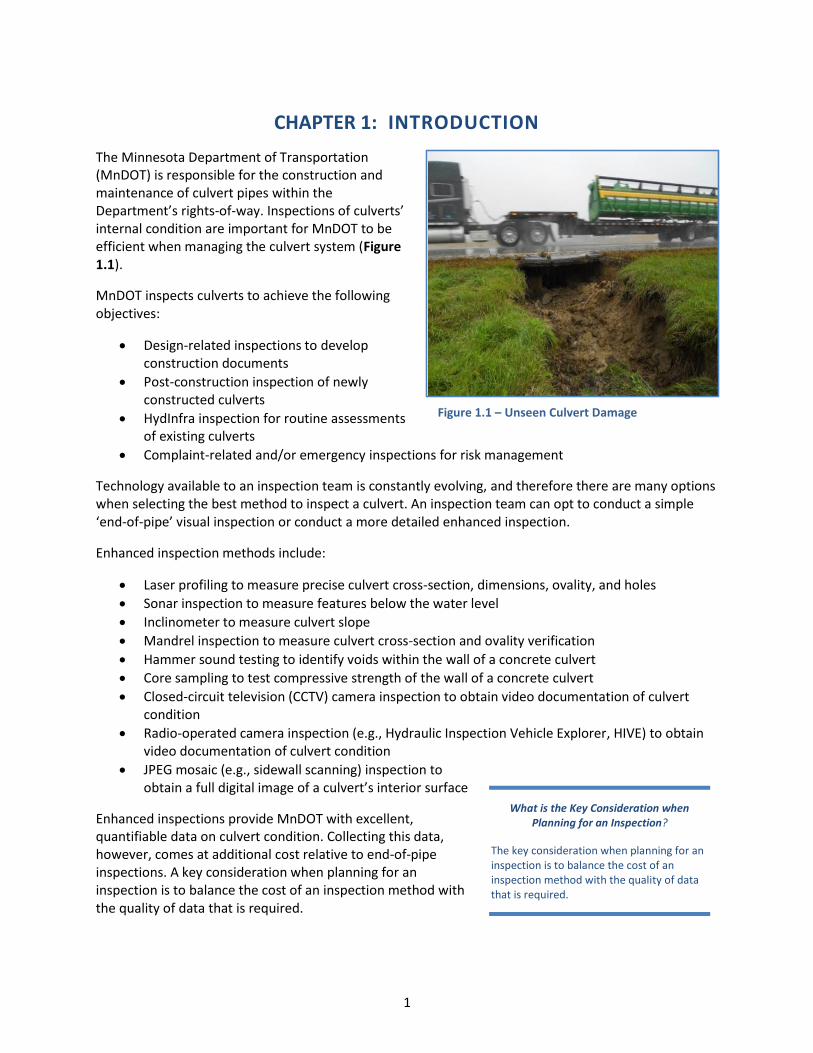
The Minnesota Department of Transportation (MnDOT) is responsible for the construction and maintenance of culvert pipes within the Department’s rights-of-way. Inspections of culverts’ internal condition are important for MnDOT to be efficient when managing the culvert system (Figure 1.1).
MnDOT inspects culverts to achieve the following objectives:
Design-related inspections to developconstruction documents
Post-construction inspection of newlyconstructed culverts
HydInfra inspection for routine assessmentsof existing culverts
Complaint-related and/or emergency inspections for risk management
Technology available to an inspection team is constantly evolving, and therefore there are many options when selecting the best method to inspect a culvert. An inspection team can opt to conduct a simple ‘end-of-pipe’ visual inspection or conduct a more detailed enhanced inspection.
Enhanced inspection methods include:
Laser profiling to measure precise culvert cross-section, dimensions, ovality, and holes
Sonar inspection to measure features below the water level
Inclinometer to measure culvert slope
Mandrel inspection to measure culvert cross-section and ovality verification
Hammer sound testing to identify voids within the wall of a concrete culvert
Core sampling to test compressive strength of the wall of a concrete culvert
Closed-circuit television (CCTV) camera inspection to obtain video documentation of culvertcondition
Radio-operated camera inspection (e.g., Hydraulic Inspection Vehicle Explorer, HIVE) to obtainvideo documentation of culvert condition
JPEG mosaic (e.g., sidewall scanning) inspection toobtain a full digital image of a culvert’s interior surface
Enhanced inspections provide MnDOT with excellent, quantifiable data on culvert condition. Collecting this data, however, comes at additional cost relative to end-of-pipe inspections. A key consideration when planning for an inspection is to balance the cost of an inspection method with the quality of data that is required.
Figure 1.1 – Unseen Culvert Damage
What is the Key Consideration when Planning for an Inspection?
The key consideration when planning for an inspection is to balance the cost of an inspection method with the quality of data that is required.
2
This guidance document is a primer on enhanced inspections and provides users with information to better select a cost-effective inspection strategy. This document includes:
Section 2 summarizes objectives of enhanced inspection.
Section 3 provides an overview of current and emerging inspection technologies.
Section 4 provides guidance on selecting enhanced inspection technologies.
Section 5 recommends best practices when implementing inspections.
Section 6 discusses cost-effectiveness of inspection technologies.
Section 7 summarizes next steps for advancing enhanced inspections at MnDOT.
Note that inspection technologies presented in this manual are most suited for culverts with a diameter less than 10 feet; however, information herein may be applicable to larger diameter culverts.
1.1 DEVELOPMENT OF BEST PRACTICES
Best practices presented in this guidance document were developed based on a combination of industry standards and MnDOT practice. These best practices are based on interviews, a review of literature, a review of MnDOT inspection data, and field inspections of a variety of culverts. Summaries of the source materials are provided in the appendices of this document.
1.1.1 Interviews
Between August 23, 2016 and September 29, 2016, CDM Smith conducted interviews and discussed enhanced inspection practices with 15 individuals. Those interviewed include representatives from MnDOT districts, Minnesota counties, and five non-Minnesota transportation departments. Interviews focused on inspection technologies, enhanced inspection procedures, and data management. Appendix A includes a list of interview questions and summaries from each interview.
1.1.2 Literature Review
MnDOT identified literature that describes inspection best practices. A total of 26 sources were summarized in the literature review. These best practices are a basis for development of guidance in this document. Refer to Appendix B for the literature review summary.
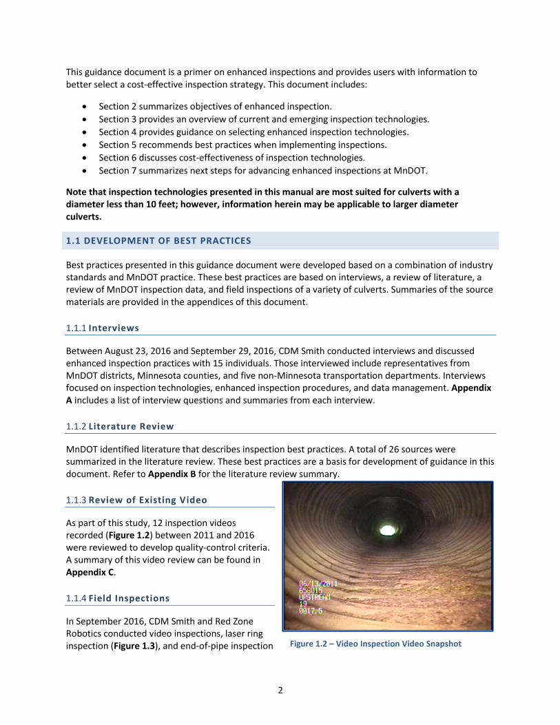
1.1.3 Review of Existing Video
As part of this study, 12 inspection videos recorded (Figure 1.2) between 2011 and 2016 were reviewed to develop quality-control criteria. A summary of this video review can be found in Appendix C.
1.1.4 Field Inspections
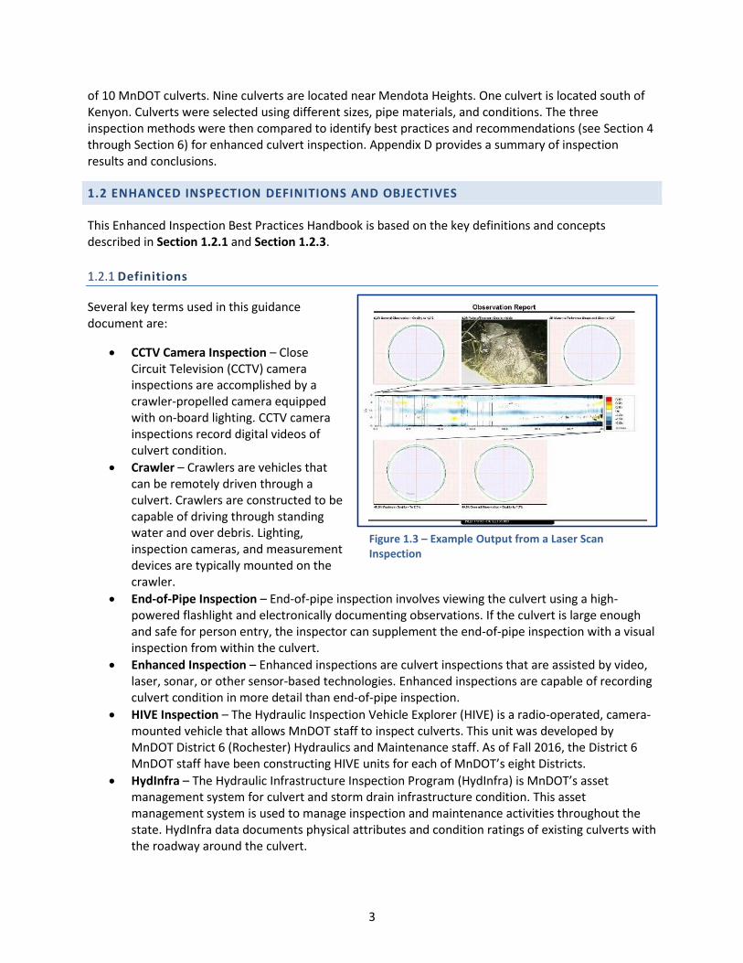
In September 2016, CDM Smith and Red Zone Robotics conducted video inspections, laser ring inspection (Figure 1.3), and end-of-pipe inspection Figure 1.2 – Video Inspection Video Snapshot
3
of 10 MnDOT culverts. Nine culverts are located near Mendota Heights. One culvert is located south of Kenyon. Culverts were selected using different sizes, pipe materials, and conditions. The three inspection methods were then compared to identify best practices and recommendations (see Section 4 through Section 6) for enhanced culvert inspection. Appendix D provides a summary of inspection results and conclusions.
1.2 ENHANCED INSPECTION DEFINITIONS AND OBJECTIVES
This Enhanced Inspection Best Practices Handbook is based on the key definitions and concepts described in Section 1.2.1 and Section 1.2.3.
1.2.1 Definitions
Several key terms used in this guidance document are:
CCTV Camera Inspection – CloseCircuit Television (CCTV) camerainspections are accomplished by acrawler-propelled camera equippedwith on-board lighting. CCTV camerainspections record digital videos ofculvert condition.
Crawler – Crawlers are vehicles thatcan be remotely driven through aculvert. Crawlers are constructed to becapable of driving through standingwater and over debris. Lighting,inspection cameras, and measurementdevices are typically mounted on thecrawler.
End-of-Pipe Inspection – End-of-pipe inspection involves viewing the culvert using a high-powered flashlight and electronically documenting observations. If the culvert is large enoughand safe for person entry, the inspector can supplement the end-of-pipe inspection with a visualinspection from within the culvert.
Enhanced Inspection – Enhanced inspections are culvert inspections that are assisted by video,laser, sonar, or other sensor-based technologies. Enhanced inspections are capable of recordingculvert condition in more detail than end-of-pipe inspection.
HIVE Inspection – The Hydraulic Inspection Vehicle Explorer (HIVE) is a radio-operated, camera-mounted vehicle that allows MnDOT staff to inspect culverts. This unit was developed byMnDOT District 6 (Rochester) Hydraulics and Maintenance staff. As of Fall 2016, the District 6MnDOT staff have been constructing HIVE units for each of MnDOT’s eight Districts.
HydInfra – The Hydraulic Infrastructure Inspection Program (HydInfra) is MnDOT’s assetmanagement system for culvert and storm drain infrastructure condition. This assetmanagement system is used to manage inspection and maintenance activities throughout thestate. HydInfra data documents physical attributes and condition ratings of existing culverts withthe roadway around the culvert.
Figure 1.3 – Example Output from a Laser Scan Inspection

4
Laser Ring Inspection – Laser ring inspection involves deploying an inspection unit that projectsa laser ring on the culvert interior to record the culvert’s dimensions and profile.
Measurement-Based Inspection – Measurement-based inspections are inspections that useenhanced technologies, mandrel, or direct/manual measurement to collect quantitativemeasurements of the culverts dimensions and features.
NASSCO Quality Standards – In 2002, the National Association of Sanitary Sewer Companies(NASSCO) developed pipe inspection standards. NASSCO methodology provides nationally-accepted guidance on best practices when conducting inspections using CCTV cameras.
Ovality – Ovality is the degree of deviation from perfect circularity of the culvert’s cross-section.A higher ovality percentage represents a more deformed culvert.
Person Entry Inspection – Person entry inspection involves physically accessing the interior ofthe culvert, manually identifying damage, and electronically documenting observations.
Rehabilitation – Rehabilitation involves repairing a culvert to return it to its initial condition orbetter. This definition is consistent with guidance in NCHRP Synthesis 303 – Assessment andRehabilitation of Existing Culverts (NCHRP, 2002).
Repair – Repair involves conducting maintenance that will keep the culvert in a uniform and safecondition. Repair does not necessarily involve restoring the pipe to its initial condition or better.This definition is consistent with guidance in NCHRP Synthesis 303 – Assessment andRehabilitation of Existing Culverts (NCHRP, 2002).
Replacement – Replacement involves constructing a completely new culvert, thereforeproviding a new service life. This definition is consistent with guidance in NCHRP Synthesis 303 –Assessment and Rehabilitation of Existing Culverts (NCHRP, 2002).
Video Recorded Inspection – Video recorded inspections use enhanced technology to inspect aculvert and obtain digital video documentation of condition.
1.2.2 Abbreviations
Abbreviations used in this document include:
Abbreviation Definition
AASHTO American Association of State Highways and Transportation Officials
ASTM American Society for Testing and Materials
ATV All Terrain Vehicles
CCTV Closed Circuit Television
CIPP Cured in Place Pipe
CMP Corrugated Metal Pipe
FPM Feet Per Minute
GB Gigabytes
GIS Geographic Information System
HDPE High Density Polyethylene
HIVE Hydraulic Inspection Vehicle Explorer
HydInfra Hydraulic Infrastructure Inspection Program
JPEG Joint Photographic Experts Group, an industry standard for imaging
MB Megabytes

5
Abbreviation Definition
MN Minnesota
MnDOT Minnesota Department of Transportation
NASSCO National Association of Sanitary Sewer Companies
NCHRP National Cooperative Highway Research Program
O&M Operations and Maintenance
OSHA Occupational Safety and Health Administration
PACP Pipe Assessment Certification Program
PDF Portable Document Format
PPE Personal Protective Equipment
RFQ Request for Qualifications
SMPTE Society of Motion Picture and Television Engineers
1.2.3 Types of Culvert Inspection
Inspecting MnDOT culverts is an essential task for the Department’s overall asset management efforts. Inspections will occur over the lifecycle of a culvert (Figure 1.4).
1.2.3.1 Design-Related Inspections
Prior to designing a project, it may be necessary to inspect culverts to identify repair, rehabilitation, or replacement needs. End-of-pipe inspections may be sufficient; however, enhanced inspection may be useful when determining cost-effective repair options.
HydInfra Inspectors in some of MnDOT’s Districts are recording inspections and suggesting repairs prior to designing construction projects. With a better view of the culvert’s interior, enhanced inspection technologies can obtain data such as culvert dimensions, condition, location of damage, and extent of damage.
1.2.3.2 Post-Construction Inspections
Post-construction inspection is required to confirm a culvert was installed per specifications, confirm the installation is within deformation tolerances, and identify conditions inside the culvert that might undermine surface pavement.
While post-construction inspections can sometimes be accomplished by a simple end-of-pipe inspection, the precision provided by enhanced inspections are useful to document acceptance of the contractor’s work. When practical to obtain, a digital video record of the culvert immediately after installation is helpful for comparison when conducting future asset inventory (i.e., HydInfra) inspections. Condition at
Figure 1.4 – Inspections Expected over the Lifecycle of a Culvert

6
installation will help MnDOT staff to identify the culvert’s degradation rate and estimate remaining service life.
Enhanced inspection technology, such as mandrel testing and laser ring scanning, can confirm a culvert’s deformation. Mandrel testing and laser ring scanning are defensible methods when disputing acceptance of work.
1.2.3.3 Condition Inspections
Throughout a culvert’s service life, MnDOT conducts periodic condition assessments. Inspection protocols are provided in the HydInfra Culvert and Storm Drainage System Inspection Manual (MnDOT, 2016). The HydInfra inspection method documents pertinent information about a culvert and identifies the need for repair.
End-of-pipe inspections can identify the general condition of the culvert; however, it is difficult to make detailed observations when damage is farther from the end of the culvert. Because of this limitation, an inspector may require a more detailed inspection using enhanced inspection methods.
1.2.3.4 Complaint or Emergency-Related Inspections
If MnDOT receives a complaint that a culvert has serious problems or is not draining properly, a complaint or emergency-related inspection will be initiated. These inspections identify culvert conditions that may be causing the complaint. Often the root cause is a partial collapse, blockage in the culvert, heavy debris, or damage during flooding/surcharging. Road surface damage may also require a culvert or storm drain pipe inspection to locate the source of the problem.
1.3 LIMITATIONS OF GUIDANCE DOCUMENT AND STAFF JUDGMENT
This guidance document is intended to present best practices and is not a substitute for engineering knowledge, experience, or judgment. MnDOT staff should consider site-specific requirements and MnDOT experience when implementing enhanced inspection work. Site-specific requirements and experience may result in variations from guidance described in this guidance document.

7
CHAPTER 2: OBJECTIVES AND TECHNOLOGY SELECTION
2.1 CULVERT INSPECTION OBJECTIVES
The purpose of a culvert inspection is to understand and document internal condition of the culvert, review external loss of bedding, identify the condition of fill around culvert aprons, and assess culvert-related damage to the associated roadway. Inspection is considered successful when the following objectives are achieved:
Informational/Benchmarking Objectives
Document characteristics of the culvert. Characteristics include length, diameter, material, transition points, lining condition, and connections.
Confirm proper installation in accordance with construction plans and specifications.
Assess condition of the culvert to schedule repairs, identify cleaning needs, track lifecycle, and anticipate replacement or rehabilitation.
Operational Objectives
Identify latent conditions affecting structural and hydraulic performance.
Identify maintenance conditions (sediment, deposits, blockages from vegetation, gravel, trash and rocks, etc.).
2.2 INSPECTION FREQUENCY AND BENCHMARKING
While developing this guidance document, a literature review (Appendix B) was conducted with the intent of identifying nationally-recognized benchmarks for enhanced culvert inspection programs. No national benchmarks were identified; however, some organizations presented relevant recommendations for implementing inspection programs.
This section summarizes inspection frequency recommendations published by MnDOT, in lieu of published benchmarks.
2.2.1 Post-Construction Inspection
Many DOT’s that have published literature on inspection frequency require, at a minimum, video and/or mandrel inspections of new culverts prior to final acceptance of a contractor’s work. The MnDOT report A Research Plan and Report on Factors Affecting Culvert Service Life in Minnesota (MnDOT, 2012) suggests that high-density polyethylene (HDPE) pipe representatives believe when a plastic culvert deforms, deformation typically occurs within seven days of construction. The American Association of State Highway and Transportation Officials (AASHTO) Load and Resistance Factor (LRFD) Bridge Construction specification and MnDOT specification 2501 requires inspection no sooner than 30 days after construction. If schedule allows, completing inspections prior to completing the road surface allows contractors the opportunity to correct poorly constructed culverts identified through inspection and prior to the highway being paved.
2.2.2 Condition Inspection Frequency
Recommendations on condition inspection frequency include:

8
The frequency of culvert inspection can be related to condition rating. If condition is good, inspections are not required as frequently. The Culvert Inventory and Inspection Manual (NYDOT, 2006) recommends that culverts in good condition should be inspected every four years. Damaged culverts that are not at risk of immediate failure should be inspected every two years. Poor condition culverts at risk of failure should be inspected annually.
Prioritize enhanced inspections on culverts that are in poor condition or are approaching their intended design life. Note that the MnDOT report A Research Plan and Report on Factors Affecting Culvert Service Life in Minnesota (MnDOT, 2012) suggests that industry sources list service life of some specially-constructed HDPE culverts as 100 years. This lifecycle assessment rarely considers the impact of freeze-thaw on service life. A Research Plan and Report on Factors Affecting Culvert Service Life in Minnesota recommends that one should assume HDPE culverts have a service life of 50 years.
The MnDOT HydInfra Culvert and Storm Drainage System Inspection Manual recommends an inspection frequency based on condition rating. Culverts in good condition are inspected on a 6-year cycle. Culverts in very poor condition are inspected every 1 to 2 years.
2.2.3 Design Inspection Frequency
It is recommended, at a minimum, that all culverts that will receive repairs or rehabilitation are visually inspected. After reviewing end-of-pipe inspection results, the design team will use their best judgment as to whether an enhanced inspection would provide additional useful design data.

9
CHAPTER 3: TECHNOLOGY
A wide variety of inspection technologies and methods are available to help MnDOT evaluate culvert condition. These inspection methods range from simple, end-of-pipe visual inspections to laser profiling that can generate advanced profiles of the culvert’s condition (Figure 3.1).
3.1 SUMMARY OF INSPECTION APPROACHES
Inspection methods are grouped into three categories:
End-of-Pipe Inspection – End-of-pipe inspection involves visually observing a culvert and documenting its condition. Measuring diameter at the inlet and outlet of a culvert is a standard part of an end-of-pipe inspection. Although physical measurements occur as part of an end-of-pipe inspection, these simple inspections are not classified in this guidance document as ‘Measurement-Based Inspections.’
Measurement-Based Inspections – Measurement-based inspections use inspection technology to obtain physical measurements and assessments of wall integrity from within the culvert. Measurements include internal diameter, ovality, slope, debris quantity, location/extent of holes in the pipe wall, or wall strength.
Video Recorded Inspection – Recorded inspections use enhanced technologies to obtain video documentation of the culvert’s condition.
3.1.1 End-of-Pipe Inspection
The easiest inspection method to implement is an end-of-pipe inspection. End-of-pipe inspection involves an inspection team looking inside a culvert and recording observations. While end-of-pipe inspection is typically the lowest cost approach, it also provides MnDOT with the least amount of quantified data. Data obtained from end-of-pipe inspection may be insufficient to meetthe inspection team’s needs. Therefore, a more advanced, enhanced inspection method would be required.
Note that end-of-pipe inspection is not considered ‘enhanced inspection’ in this guidance document. End-of-pipe inspections are discussed in this guidance document to provide a contrast with enhanced inspection technologies.
Figure 3.1 – Wire Mesh Model Generated from Laser Scan Inspection Data
Figure 3.2 – Person Entry Inspection of a Rectangular Culvert
10
3.1.1.1 Inspection Principle
End-of-pipe inspections rely on an inspector physically viewing and assessing culvert condition. The inspector will document condition by recording observations on an electronic inspection log.
End-of-pipe inspection without person entry will provide limited data. One can expect to accurately inspect approximately 5 to 30 feet from either end of the culvert. The inspection team can make general observations about culvert condition beyond 30 feet, but observations will not be detailed. End-of-pipe inspections can be used to screen a culvert; results may justify an enhanced inspection.
When safe and practical, end-of-pipe inspections can be supplemented with a person entry and visual inspection inside the culvert (Figure 3.2). Refer to Section 3.3.3 for additional information on person entry inspections.
3.1.1.2 Technology Profile
End-of-pipe inspection is summarized in Table 3.1.
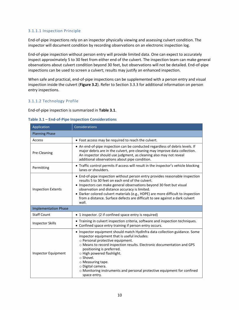
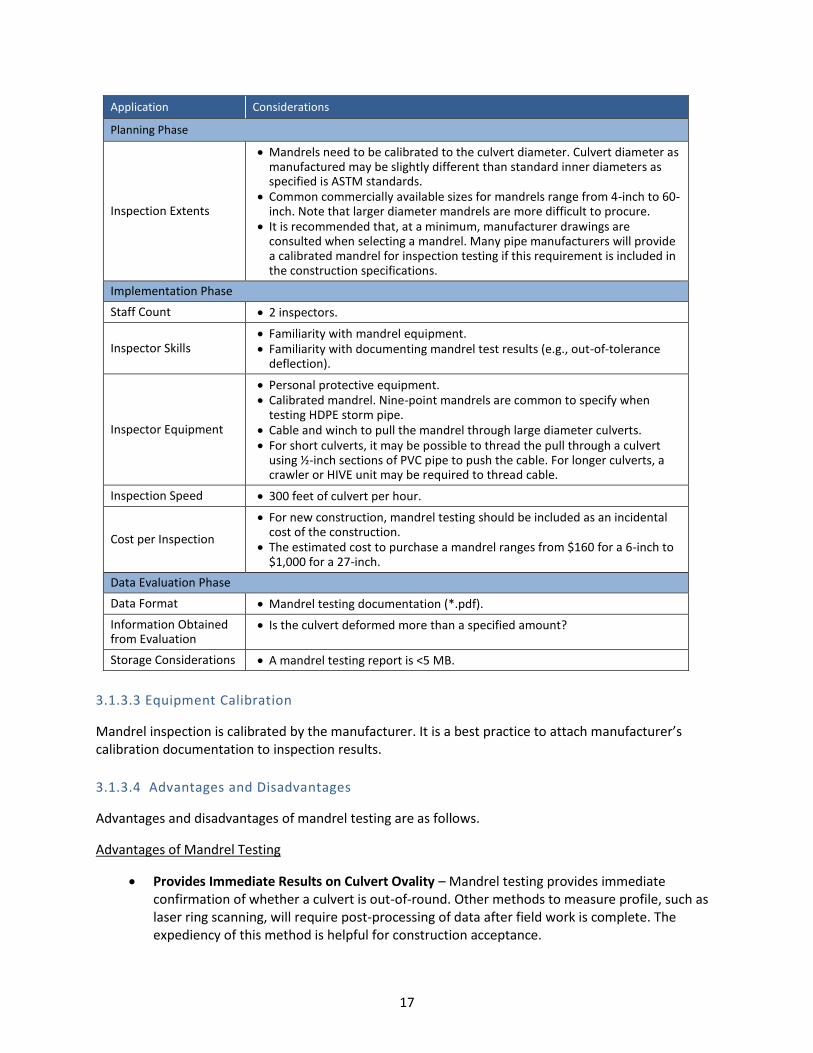
Table 3.1 – End-of-Pipe Inspection Considerations
Application Considerations
Planning Phase
Access Foot access may be required to reach the culvert.
Pre-Cleaning
An end-of-pipe inspection can be conducted regardless of debris levels. If major debris are in the culvert, pre-cleaning may improve data collection. An inspector should use judgment, as cleaning also may not reveal additional observations about pipe condition.
Permitting Traffic control permits if access will result in the inspector’s vehicle blocking
lanes or shoulders.
Inspection Extents
End-of-pipe inspection without person entry provides reasonable inspection results 5 to 30 feet on each end of the culvert.
Inspectors can make general observations beyond 30 feet but visual observation and distance accuracy is limited.
Darker colored culvert materials (e.g., HDPE) are more difficult to inspection from a distance. Surface defects are difficult to see against a dark culvert wall.
Implementation Phase
Staff Count 1 inspector. (2 if confined space entry is required)
Inspector Skills Training in culvert inspection criteria, software and inspection techniques. Confined space entry training if person entry occurs.
Inspector Equipment
Inspector equipment should match HydInfra data collection guidance. Some inspector equipment that is useful includes: o Personal protective equipment. o Means to record inspection results. Electronic documentation and GPS
positioning is preferred. o High powered flashlight. o Shovel. o Measuring tape. o Digital camera. o Monitoring instruments and personal protective equipment for confined
space entry.

11
Application Considerations
Planning Phase
Inspection Speed 3 culverts per hour for end-of-pipe inspection (20 minutes per inspection).
Cost per Inspection
Assuming an inspection speed of 3 culverts per hour, a culvert length of 200 feet and MnDOT labor of $53 per hour, it will cost MnDOT $0.09 per foot to conduct an end-of-pipe inspection. Each culvert costs approximately $13 per culvert to inspect.
Data Evaluation Phase
Data Format
Inspection documentation. GPS data export (*.csv). Inspection photography (*.jpeg or similar, if required).
Information Obtained from Evaluation
Refer to HydInfra data collection guidance for a list of from an end-of-pipe inspection.
information obtained
Storage Considerations <5 MB per inspection.
3.1.1.3 Advantages and Disadvantages
Advantages and disadvantages of end-of-pipe inspection are as follows.
Advantages of End-of-Pipe Inspection
Lowest Cost Inspection Method – End-of-pipe inspections can be accomplished by MnDOT staff and typically do not require mobilization of special equipment. This type of inspection is recorded with Global Positioning System (GPS) data collection equipment. Electronic data is then input to the HydInfra database. Relative to enhanced inspections, MnDOT can conduct end-of-pipe inspections faster and at a significantly lower cost than more complex enhanced inspections. The only cost for an end-of-pipe inspection is staff time to inspect and document condition.
Fastest Inspection Speed – MnDOT staff report that end-of-pipe inspection can be accomplished in less than 20 minutes per culvert. Data is recorded at the site, and results are available immediately after the inspection is complete.
Appropriate for Condition Screening – End-of-pipe inspection is the best method to screen culvert condition and justify a costlier enhanced inspection. In addition, visual pre-screening of culverts can identify maintenance issues (e.g., heavy sediment) that may impact the quality of a future enhanced inspection.
Facilitates a Full-System (Road and Culvert) Evaluation – Enhanced inspections, particularly those conducted by outside contractors, are often limited to the narrow scope of the culvert to be inspected. For example, a video inspection often only obtains video documentation of the culvert. If damage exists adjacent to the culvert or at the road surface, this information is often not recorded.
Disadvantages of End-of-Pipe Inspection
Limited View in Culvert – End-of-pipe inspections that are not supplemented with person entry provides a limited view of the culvert. Inspection data is accurate within 30 feet of the inlet and outlet, but less accurate in the center of the culvert as the lighting diminishes.

12
Greater Risk of Measurement Inaccuracy – The inspection team manually collects physical measurements of a culvert. Compared to enhanced inspections, accuracy of physical measurements is limited.
One important measurement is the distance from a culvert’s inlet to observed damage. If the damage is deep in the culvert, an inspection team will often need to estimate distance. An estimate of damage location is often insufficient for contractors as a determination of where to excavate.
End-of-pipe inspections cannot accurately measure percent deflection in a culvert. One can expect an inspection team to observe deflections within 10 percent of the actual percent out-of-round. That is, an inspector typically can accurately recognize deflections of 10 percent, 20 percent, 30 percent, etc. This measurement resolution is not accurate enough to support construction acceptance.
3.1.2 Measurement-Based Inspection
Measurement-based inspections are enhanced inspections where the inspection team utilizes technology to obtain calibrated and quantified measurements of a culvert’s attributes and damage. There are three types of measurement-based inspection:
Multiple Sensor Inspection.
Mandrel Inspection.
Person Entry-Facilitated (Hammer Sound Testing and Core Sample Testing) Inspection.
3.1.2.1 Multiple Sensor Inspection
Inspection Principle
A multiple sensor robotic inspection involves deploying a remote-controlled crawler into a culvert and using on-board sensors to record measurements. Multiple sensor inspection units are customizable and contractors will mount different instruments based on culvert size, material, and data needs (Figure 3.3).
Common sensors that are mounted on a multiple sensor inspection unit are:
Sonar Profilometry – If a culvert is partially submerged, the inspection unit can be constructed on a floating platform. A sonar sensor is attached to this platform. The sonar sensor uses sound to produce an image of the culvert below the water line. Sonar sensors are used to quantify debris below the water line and to quantify invert degradation.
Inclinometer Measurement – An inclinometer is a sensor that mounts to a crawler and detects slope. Inclinometers are used to measure sags in the liner or to verify that culverts were constructed with the designed slope.
Figure 3.3 – Multiple Inspection Unit
13
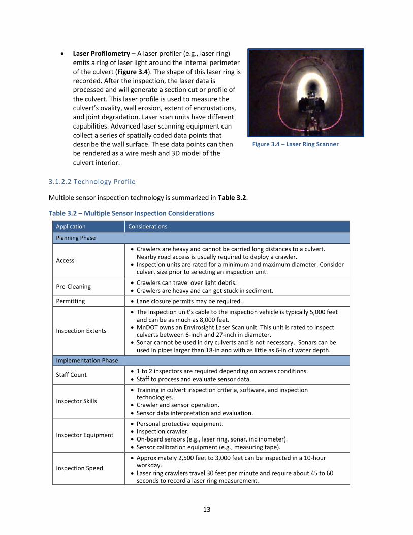
Laser Profilometry – A laser profiler (e.g., laser ring) emits a ring of laser light around the internal perimeter of the culvert (Figure 3.4). The shape of this laser ring is recorded. After the inspection, the laser data is processed and will generate a section cut or profile of the culvert. This laser profile is used to measure the culvert’s ovality, wall erosion, extent of encrustations, and joint degradation. Laser scan units have different capabilities. Advanced laser scanning equipment can collect a series of spatially coded data points that describe the wall surface. These data points can then be rendered as a wire mesh and 3D model of the culvert interior.
Figure 3.4 – Laser Ring Scanner
3.1.2.2 Technology Profile
Multiple sensor inspection technology is summarized in Table 3.2.
Table 3.2 – Multiple Sensor Inspection Considerations
Application Considerations
Planning Phase
Access
Crawlers are heavy and cannot be carried long distances to a culvert. Nearby road access is usually required to deploy a crawler.
Inspection units are rated for a minimum and maximum diameter. Consider culvert size prior to selecting an inspection unit.
Pre-Cleaning Crawlers can travel over light debris. Crawlers are heavy and can get stuck in sediment.
Permitting Lane closure permits may be required.
Inspection Extents
The inspection unit’s cable to the inspection vehicle is typically 5,000 feet and can be as much as 8,000 feet.
MnDOT owns an Envirosight Laser Scan unit. This unit is rated to inspect culverts between 6-inch and 27-inch in diameter.
Sonar cannot be used in dry culverts and is not necessary. Sonars can be used in pipes larger than 18-in and with as little as 6-in of water depth.
Implementation Phase
Staff Count 1 to 2 inspectors are required depending on access conditions. Staff to process and evaluate sensor data.
Inspector Skills
Training in culvert inspection criteria, software, and inspection technologies.
Crawler and sensor operation. Sensor data interpretation and evaluation.
Inspector Equipment
Personal protective equipment. Inspection crawler. On-board sensors (e.g., laser ring, sonar, inclinometer). Sensor calibration equipment (e.g., measuring tape).
Inspection Speed
Approximately 2,500 feet to 3,000 feet can be inspected in a 10-hour workday.
Laser ring crawlers travel 30 feet per minute and require about 45 to 60 seconds to record a laser ring measurement.

14
Application Considerations
Planning Phase
Inspection contractors were contacted when developing this guidance document. It was stated that one should expect about a 30-day turnaround from the date of inspection to receipt of inspection results.
Cost per Inspection
If the MnDOT laser ring unit is used, the cost of this inspection is the staff labor to collect and process data.
In 2016, contractor pricing (Red Zone Robotics) included a fixed mobilization of $8,500 plus $6.50 per foot inspected. Often, CCTV camera inspection is conducted along with a multiple sensor inspection. CCTV camera-facilitated inspection adds approximately $2 per foot to the unit cost.
The cost of purchasing a new multiple sensor inspection unit is estimated at between $140,000 and $230,000.
Data Evaluation Phase
Data Format
Inspection summary and report (*.pdf). Contractors can provide raw inspection data that can be manipulated by
MnDOT. This data is typically viewed using proprietary viewing software provided by the contractor. Often, this data is large and must be provided by portable hard drive.
Information Obtained from Evaluation
Laser Scanning o Location and extent of ovality deformations (i.e., % out of round). o Location and extent of degraded wall surface (i.e., erosion, holes). o Location and extent of wall deposits. o 3D wire mesh model (advanced equipment).
Sonar Scanning o Location and depth of debris below water. o Debris volume.
Inclinometer Scanning o Slope of invert.
Storage Considerations Inspection report is 1 MB to 5 MB per culvert. Raw data size varies from several MB to GB.
3.1.2.3 Size Considerations for Laser Scanning
Inspection contractors will select an inspection unit based on culvert diameter. Laser rings are rated for a maximum diameter and intensity diffuses over a distance. If the culvert is too large, the laser will not be able to record accurate measurements. If the culvert is too small, the laser ring cannot fit in the culvert. Laser scan units operated by Red Zone Robotics were reviewed and a summary of size and capabilities are as follows:
Remote controlled, untethered laser scanning units are available to serve pipes that are 8-inch to 12-inch in diameter. These units can measure culvert profile.
Medium size laser scan units are available to measure culverts between 12-inch and 48-inch. These units have more functionality than the smaller, untethered crawlers. Medium sized laser scan units can measure ovality, bend radius, and record alignment.
The largest laser scan units can inspect culverts between 36-inch and 118-inch. Availability of these large units are limited and specialty contractors typically require extra lead time to mobilize.

15
Equipment Calibration
Multiple sensor inspection equipment requires calibration of the sensor equipment to ensure accurate measurements. Calibration procedures are typically conducted prior to mobilization and should be conducted as recommended by the equipment manufacturer.
3.1.2.4 Sonar Scanning Considerations
Sonar scanners emit an acoustic signal below the water line to generate a profile of the culvert’s invert. Sonar scanners identify debris in a culvert. Sonar results are often used to quantify debris volume.
MnDOT owns a Teledyne Blueview BV1350 Sonar Scanner. This scanner is a stationary unit that can map a culvert’s invert. The Teledyne Blueview Sonar Scanner requires at least 3 feet of water in the culvert. Because of this limitation, the Teledyne Blueview Sonar Scanner is suitable for large diameter culverts with a high water level. One may choose to deploy this scanner in a culvert to measure a large sag observed in the line.
Another common sonar technology is a crawler or float-mounted profiling system. Sonar profiles are an additional sensor that one can mount to a multiple sensor inspection unit. These sonars often work in tandem with laser scanning; the laser maps the profile above the water level and the sonar maps below the water level. Crawler-mounted sonars must be selected based on culvert diameter. The smallest sonars can be deployed in culverts that are 12-inch in diameter and can profile an invert with 4 inches of water. The largest sonar profilers can survey culverts that are 18 feet in diameter.
3.1.2.5 Advantages and Disadvantages
Advantages and disadvantages of multiple sensor inspection are as follows.
Advantages of Multiple Sensor Inspection
Provides Quantitative Culvert Geometry Data – Laser profile scanning provides exact geometric dimensions of a culvert’s interior. The Red Zone Robotics laser scanning unit used in the 2016 inspection detected ovality within 0.1 percent. Laser scan results are useful in proving excessing deflection in new plastic or metal culverts.
Documents Culvert Alignment – Some inclinometers have the capability to record slope and a crawler’s coordinates in a culvert. These sensors can be used to field verify culvert alignment in an ArcGIS database.
MnDOT Owns Laser Scanning Equipment – Contracting laser scanning services is expensive. MnDOT recently invested in a laser ring inspection unit. The cost to conduct in-house inspections of culverts is significantly less than retaining a contractor. Incorporating laser ring inspections into HydInfra and construction inspections would produce beneficial data on culvert ovality.
Disadvantages of Multiple Sensor Inspection
Inspecting Unit’s Sensitivity to Site Conditions – The inspection crawler is heavy and has difficulty navigating culverts with inverts in poor condition.
Inspection Unit’s Sensitivity to Culvert Size – Laser ring inspection units are designed and calibrated to accurately measure culverts of a certain diameter. That is, a small diameter culvert laser will not have the power to inspect a large diameter culvert. Conversely, a large diameter
16
culvert laser will be too large to deploy a smaller culvert. MnDOT’s Envirosight laser scan unit is rated to inspect culverts between 6-inch and 27-inch in diameter.
Lack of Local Contractors – As of 2016, no local contractors provide multiple sensor inspection services. If MnDOT needs to contract this work, an out-of-state contractor would be retained. The nearest contractors that were identified to serve Minnesota are located in Ohio and Kansas.
Data Processing Time – Laser scan data requires several weeks to process. Approximately 300 feet of culvert was scanned in 2016. Results were received four weeks after field work was complete. If laser scan results are needed to meet a project’s schedule, MnDOT should discuss schedule with the inspection team prior to mobilization.
Not Applicable for All Culvert Materials – Laser are not effective for corrugated metal culverts with spiral patterning.
3.1.3 Mandrel Inspection Technology
3.1.3.1 Inspection Principle
Mandrel testing is accomplished by pulling a deflection gauge through a plastic culvert. A standard configuration for mandrels is to use a nine-fin design with the fins evenly spaced in a circular pattern. Mandrel testing is conducted to determine whether the ovality of a culvert is within accepted tolerances. MnDOT and AASHTO consider a culvert to be out-of-tolerance if the cross-sectional area is deformed more than five percent. Because of its susceptibility to deformation, mandrel tests are often conducted on newly constructed plastic culverts.
3.1.3.2 Technology Profile
Mandrel testing technology is summarized in Table 3.3.
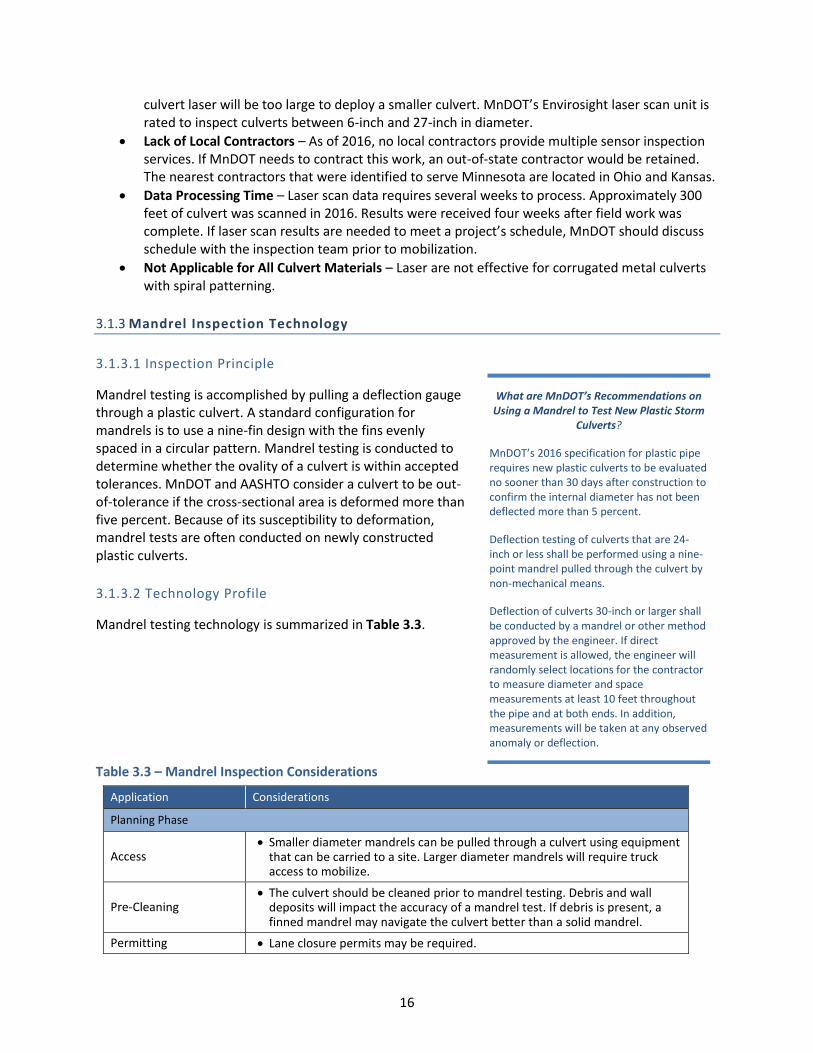
Table 3.3 – Mandrel Inspection Considerations
What are MnDOT’s Recommendations on Using a Mandrel to Test New Plastic Storm
Culverts?
MnDOT’s 2016 specification for plastic pipe requires new plastic culverts to be evaluated no sooner than 30 days after construction to confirm the internal diameter has not been deflected more than 5 percent.
Deflection testing of culverts that are 24-inch or less shall be performed using a nine-point mandrel pulled through the culvert by non-mechanical means.
Deflection of culverts 30-inch or larger shall be conducted by a mandrel or other method approved by the engineer. If direct measurement is allowed, the engineer will randomly select locations for the contractor to measure diameter and space measurements at least 10 feet throughout the pipe and at both ends. In addition, measurements will be taken at any observed anomaly or deflection.
Application Considerations
Planning Phase
Access Smaller diameter mandrels can be pulled through a culvert using equipment
that can be carried to a site. Larger diameter mandrels will require truck access to mobilize.
Pre-Cleaning The culvert should be cleaned prior to mandrel testing. Debris and wall
deposits will impact the accuracy of a mandrel test. If debris is present, a finned mandrel may navigate the culvert better than a solid mandrel.
Permitting Lane closure permits may be required.
17
Application Considerations
Planning Phase
Inspection Extents
Mandrels need to be calibrated to the culvert diameter. Culvert diameter as manufactured may be slightly different than standard inner diameters as specified is ASTM standards.
Common commercially available sizes for mandrels range from 4-inch to 60-inch. Note that larger diameter mandrels are more difficult to procure.
It is recommended that, at a minimum, manufacturer drawings are consulted when selecting a mandrel. Many pipe manufacturers will provide a calibrated mandrel for inspection testing if this requirement is included in the construction specifications.
Implementation Phase
Staff Count 2 inspectors.
Inspector Skills Familiarity with mandrel equipment. Familiarity with documenting mandrel test results (e.g., out-of-tolerance
deflection).
Inspector Equipment
Personal protective equipment. Calibrated mandrel. Nine-point mandrels are common to specify when
testing HDPE storm pipe. Cable and winch to pull the mandrel through large diameter culverts. For short culverts, it may be possible to thread the pull through a culvert
using ½-inch sections of PVC pipe to push the cable. For longer culverts, a crawler or HIVE unit may be required to thread cable.
Inspection Speed 300 feet of culvert per hour.
Cost per Inspection
For new construction, mandrel testing should be included as an incidental cost of the construction.
The estimated cost to purchase a mandrel ranges from $160 for a 6-inch to $1,000 for a 27-inch.
Data Evaluation Phase
Data Format Mandrel testing documentation (*.pdf).
Information Obtained from Evaluation
Is the culvert deformed more than a specified amount?
Storage Considerations A mandrel testing report is <5 MB.
3.1.3.3 Equipment Calibration
Mandrel inspection is calibrated by the manufacturer. It is a best practice to attach manufacturer’s calibration documentation to inspection results.
3.1.3.4 Advantages and Disadvantages
Advantages and disadvantages of mandrel testing are as follows.
Advantages of Mandrel Testing
Provides Immediate Results on Culvert Ovality – Mandrel testing provides immediate confirmation of whether a culvert is out-of-round. Other methods to measure profile, such as laser ring scanning, will require post-processing of data after field work is complete. The expediency of this method is helpful for construction acceptance.

18
Difficult to Dispute Results – Mandrel testing is a pass-fail test with low potential for different interpretations of results. If the mandrel cannot travel through the culvert because it is deflected beyond construction tolerances, it is difficult for a contractor to disagree with the results.
Disadvantages of Mandrel Testing
Limited Data on Deflections – Mandrel testing only identifies if a culvert is out-of-round at a single location and to an extent that exceeds a single deflection measurement (i.e., a result may be that culvert X is deflected more than 5 percent in at least one location). The accuracy of a mandrel test may also be affected by debris and deposits reducing pipe diameter. Other enhanced inspection methods, such as laser ring scanning, will quantify the percent deflection and identify the number of out-of-tolerance deflections in a culvert.
Requires Coordination with Culvert Manufacturer – The nominal size of a culvert may not match the fabricated internal diameter. Consequently, a contractor conducting a mandrel test often must obtain a calibrated mandrel from the pipe manufacturer prior to conducting an acceptance test.
Difficult to Detect Laterally Offset Joints – While mandrels can detect joints that have a perpendicular offset, this technology is not reliable when identifying lateral offsets.
3.1.4 Hammer Sound Testing (Person Entry -Facilitated Inspection)
3.1.4.1 Inspection Principle
When a concrete pipe’s steel reinforcement corrodes, this corrosion can create voids inside the culvert wall. If rebar corrosion is suspected or major spalling is noted, an inspector may opt to conduct a hammer sound test on the culvert to identify the extent of voids within the pipe. Hammer sound testing involves an inspector tapping the wall of a concrete pipe. Voids that result from outer wall or interior degradation or rebar deterioration will sound different than a structurally stable culvert. Hammer sound testing is a quick and inexpensive method to evaluate the integrity of a concrete culvert, but does require experienced inspectors. Note that hammer sound testing is not an effective method to test metal or plastic culverts.
3.1.4.2 Technology Profile
Hammer sound testing is summarized in Table 3.4.
Is Hammer Sound Testing also known as a Schmidt Hammer Test?
No, a Schmidt Hammer test is a different type of internal condition assessment. Schmidt Hammer testing uses a special spring loaded hammer that fires into the culvert wall and then rebounds. The number of rebounds correlates to the compressive strength of a culvert wall.
The accuracy of Schmidt Hammer testing is relatively low (± 15% to 20% of compressive strength). Consequently, this test is not detailed further in this document. See Section 2.3.4 for a more precise method to measure compressive strength.

19
Table 3.4 – Hammer Sound Testing Considerations
Application Considerations
Planning Phase
Access Foot access to the culvert.
Pre-Cleaning The culvert’s invert must be sufficiently clean to allow for safe person
access. The culvert wall in the test location must be clean and free from deposits.
Permitting Confined space entry (if applicable).
Inspection Extents
Hammer sound testing can only be conducted from within the culvert. Person entry is required.
Hammer sound testing can only be conducted on concrete pipe. This test does not work on metal or plastic culverts.
Implementation Phase
Staff Count 1 inspector to conduct the hammer sound testing. Depending on the
culvert’s condition and size, the inspector may require a second staff member to facilitate a safe entry.
Inspector Skills Experience interpreting the sounds of sound and degraded culverts.
Inspector Equipment
Common carpenter hammer. Personal protective equipment. Clipboard and inspection documents. High powered flashlight. Measuring tape. Digital camera.
Inspection Speed One hammer testing location completed every 5 minutes.
Cost per Inspection Staff labor assumed at $53 per hour. Assuming a hammer test is conducted
every 10 feet in a culvert, the cost of a hammer sound test is approximately $0.44 per linear foot.
Data Evaluation Phase
Data Format Hammer testing results (*.pdf).
Information Obtained from Evaluation
Locations with voids or rebar deterioration behind the culvert wall.
Storage Considerations Hammer testing report is <5 MB.
3.1.4.3 Equipment Calibration
Hammer sound testing is conducted with a common carpenter’s hammer. Inspectors conducting a hammer test will need experience interpreting the difference between a sound culvert and a culvert with voids within the wall. Prior to conducting a hammer sound test on a culvert with unknown condition, it may be beneficial to identify culverts with known deterioration and provide inspectors with a hands-on opportunity to test the pipe.
3.1.4.4 Advantages and Disadvantages
Advantages and disadvantages of hammer sound testing are as follows.
20
Advantages of Hammer Sound Testing
Low Cost, Nondestructive Method to Assess Concrete Condition – Hammer sound testing is an excellent, low-cost method of evaluating whether rebar is degraded or there are voids beyond a culvert wall. The only significant cost is labor time to conduct the test.
Disadvantages of Hammer Sound Testing
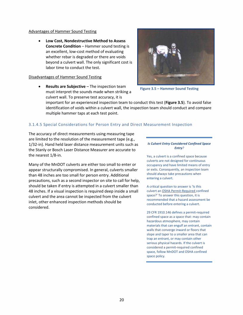
Results are Subjective – The inspection team must interpret the sounds made when striking a culvert wall. To preserve test accuracy, it is important for an experienced inspection team to conduct this test (Figure 3.5). To avoid false identification of voids within a culvert wall, the inspection team should conduct and compare multiple hammer taps at each test point.
3.1.4.5 Special Considerations for Person Entry and Direct Measurement Inspection
The accuracy of direct measurements using measuring tape are limited to the resolution of the measurement tape (e.g., 1/32-in). Hand held laser distance measurement units such as Is Culvert Entry Considered Confined Space
Entry?
Yes, a culvert is a confined space because culverts are not designed for continuous occupancy and have limited means of entry or exits. Consequently, an inspection team should always take precautions when entering a culvert.
A critical question to answer is ‘Is this culvert an OSHA Permit-Required confined space?’ To answer this question, it is recommended that a hazard assessment be conducted before entering a culvert.
29 CFR 1910.146 defines a permit-required confined space as a space that: may contain hazardous atmosphere, may contain materials that can engulf an entrant, contain walls that converge inward or floors that slope and taper to a smaller area that can trap an entrant, or may contain other serious physical hazards. If the culvert is considered a permit-required confined space, follow MnDOT and OSHA confined space policy.
the Stanly or Bosch Laser Distance Measurer are accurate to the nearest 1/8-in.
Many of the MnDOT culverts are either too small to enter or appear structurally compromised. In general, culverts smaller than 48 inches are too small for person entry. Additional precautions, such as a second inspector on site to call for help, should be taken if entry is attempted in a culvert smaller than 48 inches. If a visual inspection is required deep inside a small culvert and the area cannot be inspected from the culvert inlet, other enhanced inspection methods should be considered.
Figure 3.5 – Hammer Sound Testing

21
3.1.5 Core Sampling Test (Person Entry Facilitated Inspection)
3.1.5.1 Inspection Principle
Core sampling is a destructive test to identify the compressive strength of a concrete culvert wall. This test involves collecting a small, cylindrical core sample from the wall. Once the sample is collected, the testing team will immediately patch the sample location with a non-shrink grout.
The sample is delivered to a testing laboratory and tested for compressive strength. Compressive strength is compared against the culvert’s design strength to determine whether the wall has degraded.
3.1.5.2 Technology Profile
Core sample testing is summarized in Table 3.5.
Which Tests are Conducted on a Core Sample?
The testing laboratory should conduct a compressive strength test in accordance with ASTM C39 – Standard Test Method for Compressive Strength of Cylindrical Concrete Specimens.
Table 3.5 – Core Sample Testing Considerations
Application Considerations
Planning Phase
Access Foot access to the culvert.
Pre-Cleaning The culvert’s invert needs to be sufficiently clean to allow for safe person
access. The culvert wall at the test location must be clean and free from deposits.
Permitting Confined space entry (if applicable).
Inspection Extents Core sampling can only be conducted from within the culvert. Person entry
is required. Core sampling can only be conducted on concrete pipe.
Implementation Phase
Staff Count 1 to 2 inspectors required. Materials testing laboratory staff.
Inspector Skills Experience collecting core samples. Experience patching the culvert wall. Lab testing experience.
Inspector Equipment
Personal protective equipment. Core sampling device. Grout to patch the sample location. Clipboard and inspection documents. High powered flashlight. Measuring tape. Digital camera.
Inspection Speed 4 core samples can be collected per day. Lab evaluation typically requires a 1- to 2-week turnaround.
Cost per Inspection $1,400 per sample. Approximately $900 to collect a sample, $200 to
conduct lab testing, and $300 to prepare a summary report.
Data Evaluation Phase
Data Format Core sample testing results (*.pdf).

22
Application Considerations
Planning Phase
Inspection photography (*.jpeg).
Information Obtained from Evaluation
Wall compressive strength.
Storage Considerations Core sample testing report is <3 MG.
3.1.5.3 Equipment Calibration
Compression testing equipment is calibrated in the laboratory.
3.1.5.4 Advantages and Disadvantages
Advantages of Core Sampling
Quantitative Material Test – Core sampling is one of the only inspection methods presented herein that can quantify strength of the culvert.
Disadvantages of Core Sampling
Cannot be Conducted on Small Diameter Culverts – Core sampling is conducted on larger diameter (48-inch or greater) culverts that can be accessed by person entry. It is difficult to collect a core sample on small diameter culverts.
Cannot be Conducted on Non-Concrete Culverts – Core sampling can only be conducted on concrete culverts.
Low Representation of Total Culvert Wall Area – A small sample of the culvert’s wall is tested. The test cylinder may not be representative of the entire culvert. The inspection team should strategically select the test location to obtain best results (i.e., test pipe walls near observed damage).
3.1.6 Closed Circuit Television Camera Inspection
Closed circuit television (CCTV) camera inspections are the most common enhanced inspection method to document a culvert’s internal condition (Figure 3.6). MnDOT owns several CCTV camera crawlers and can conduct an inspection with in-house staff. If in-house staff are not available, video inspection is a common practice in the industry and many contractors are available throughout the state.
3.1.6.1 Inspection Principle
CCTV camera inspections involve deploying a crawler through a culvert. The crawler is equipped with an on-board CCTV camera, lighting, and distance logger. The camera
Figure 3.6 – Image Capture from CCTV Camera Inspection

23
operator remotely drives the crawler through the culvert. When damage is encountered, the operator stops to assess and record the damage. Digital video is then delivered to engineering staff for review and/or archived for future reference.
3.1.6.2 Technology Profile
Video recorded inspection is summarized in Table 3.6.
Table 3.6 – CCTV Camera Inspection Considerations
Application Considerations
Planning Phase
Access
Most CCTV camera inspection crawlers are operated from a truck. Consequently, culverts inspected by CCTV camera should be accessible by vehicle.
Some contractors have smaller units that can be delivered to a site by ATV.
Pre-Cleaning Crawlers can travel over light debris.
Permitting Lane closure permits may be required to access the site.
Inspection Extents
CCTV camera inspections are constrained by culvert size. The camera and lighting should be sized for the culvert that will be inspected.
Many CCTV crawlers are able to be modified to better suit site conditions. Different wheels can be affixed to the crawler in the field to better fit the camera in the culvert.
Implementation Phase
Staff Count 1 inspector. A second staff member may be required if the camera is large and must be
carried to the culvert.
Inspector Skills Training in culvert inspection criteria, software and inspection techniques. Crawler and inspection software operation.
Inspector Equipment
Personal protective equipment. CCTV camera mounted on an inspection crawler.
Floating pontoon and winch for partially submerged culverts. Camera calibration equipment (e.g., measuring tape, video image
calibration).
Inspection Speed 300 feet of inspection per 10 minutes (30 fpm).
Cost per Inspection
In 2016, typical contractor pricing for a CCTV camera inspection ranges from $1 per foot to $3 per foot.
Assuming an inspection speed of 30 fpm, travel/site setup/takedown of 45 minutes per site, a culvert length of 200 and MnDOT labor of $53 per hour, it will cost MnDOT $0.23 per foot to conduct CCTV inspection.
The cost to purchase a new CCTV camera is estimated at $100,000 - $120,000. In addition, a large truck is required to transport the camera.
Data Evaluation Phase
Data Format
Inspection summary and report (*.pdf).
Inspection video (*.mpeg). Inspection database file (*.mdb, *.csv or *.ptd; optional depending on
inspection need).
Information Obtained from Evaluation
Location of internal culvert damage. Extent of culvert damage.
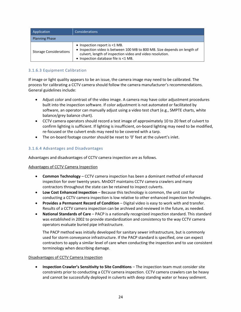
24
Application Considerations
Planning Phase
Storage Considerations
Inspection report is <1 MB. Inspection video is between 100 MB to 800 MB. Size depends on length of
culvert, length of inspection video and video resolution. Inspection database file is <1 MB.
3.1.6.3 Equipment Calibration
If image or light quality appears to be an issue, the camera image may need to be calibrated. The process for calibrating a CCTV camera should follow the camera manufacturer’s recommendations. General guidelines include:
Adjust color and contrast of the video image. A camera may have color adjustment procedures built into the inspection software. If color adjustment is not automated or facilitated by software, an operator can manually adjust using a video test chart (e.g., SMPTE charts, white balance/grey balance chart).
CCTV camera operators should record a test image of approximately 10 to 20 feet of culvert to confirm lighting is sufficient. If lighting is insufficient, on-board lighting may need to be modified, re-focused or the culvert ends may need to be covered with a tarp.
The on-board footage counter should be reset to ‘0’ feet at the culvert’s inlet.
3.1.6.4 Advantages and Disadvantages
Advantages and disadvantages of CCTV camera inspection are as follows.
Advantages of CCTV Camera Inspection
Common Technology – CCTV camera inspection has been a dominant method of enhanced inspection for over twenty years. MnDOT maintains CCTV camera crawlers and many contractors throughout the state can be retained to inspect culverts.
Low Cost Enhanced Inspection – Because this technology is common, the unit cost for conducting a CCTV camera inspection is low relative to other enhanced inspection technologies.
Provides a Permanent Record of Condition – Digital video is easy to work with and transfer. Results of a CCTV camera inspection can be archived and reviewed in the future, as needed.
National Standards of Care – PACP is a nationally recognized inspection standard. This standard was established in 2002 to provide standardization and consistency to the way CCTV camera operators evaluate buried pipe infrastructure.
The PACP method was initially developed for sanitary sewer infrastructure, but is commonly used for storm conveyance infrastructure. If the PACP standard is specified, one can expect contractors to apply a similar level of care when conducting the inspection and to use consistent terminology when describing damage.
Disadvantages of CCTV Camera Inspection
Inspection Crawler’s Sensitivity to Site Conditions – The inspection team must consider site constraints prior to conducting a CCTV camera inspection. CCTV camera crawlers can be heavy and cannot be successfully deployed in culverts with deep standing water or heavy sediment.

25
Potential for Image Distortion – Image quality can be impacted by condition in a culvert. Prior to accepting CCTV camera work, one should confirm the video is centered in the culvert, has acceptable lighting, and the camera lens is clean.
Cumbersome Data Storage – Digital video data can be large (i.e., 100 MB to 800 MB). Maintaining an archive of historic inspection videos will require significant server space.
Operator Experience – A trained operator is required to conduct a CCTV camera inspection. The operator needs to be familiar with driving the crawler, identifying defects and best practices for capturing a good video image.
3.2 INNOVATIVE OR EMERGING TECHNOLOGIES
Several innovative technologies were identified through a literature review and interviews. Innovative or emerging inspection technologies include:
Hydraulic Inspection Vehicle Explorer (HIVE) Camera Inspection.
JPEG Mosaic Inspection.
3.2.1 HIVE Inspection
3.2.1.1 Inspection Principle
Staff in the MnDOT Rochester District developed a light-weight alternative to a traditional CCTV crawler. The HIVE is a smaller, more maneuverable version of a standard CCTV camera unit (Figure 3.7). Similar to a CCTV crawler, the HIVE is equipped with on-board lighting and a video camera capable of panning and tilting. The HIVE is radio controlled by an inspector located adjacent to the culvert. The inspector remotely drives through the culvert, stopping and recording damage. Video imagery is transmitted by wi-fi signal to a tablet and reviewed by the inspector.
3.2.1.2 Technology Profile
HIVE inspection is summarized in Table 3.7.
Table 3.7 – HIVE Inspection Considerations
How Was the HIVE Developed?
The HIVE was developed by MnDOT staff as a low-cost alternative to CCTV camera inspection. MnDOT staff are building HIVE units as a tool for all Districts in the State.
Application Considerations
Planning Phase
Access The HIVE camera is small compared to traditional CCTV inspection cameras.
This unit can be carried to a remote site.
Pre-Cleaning The HIVE is designed to crawl over debris. The unit is light, so it can travel
over sediment that larger CCTV cameras would sink in.
Figure 3.7 – HIVE Camera Unit

26
Application Considerations
Permitting No permits are required unless the operator must block traffic to unload
the camera.
Inspection Extents
HIVE can inspect culverts 12 inches and larger. HIVE camera and car are waterproof. The inspector should evaluate whether on-board lighting for the HIVE unit is
sufficient for culvert diameter. Lighting may not be strong enough to illuminate the crown of large diameter (>48-inch) culverts.
Implementation Phase
Staff Count 1 inspector.
Inspector Skills Training in culvert inspection criteria, software and inspection techniques. HIVE unit operator training.
Inspector Equipment
Personal protective equipment. HIVE inspection unit. Windows based tablet to control HIVE. GPS Add-On and Inspection Software.
Inspection Speed 300 feet of inspection per 10 minutes (30 fpm).
Cost per Inspection
HIVE cameras are an innovative inspection method used by MnDOT. These units cost approximately $1,500 to $2,000 to construct.
Assuming an inspection speed of 30 fpm, travel / site setup / takedown of 45 minutes per site, a culvert length of 200 and MnDOT labor of $53/hr, it will cost MnDOT $0.23/ft to conduct a HIVE camera inspection.
Data Evaluation Phase
Data Format Inspection video (*.mpeg).
Information Obtained from Evaluation
Location and image of internal culvert damage.
Storage Considerations Inspection video is between 100 MB and 1 GB. Size depends on length of
culvert and length of inspection video.
3.2.1.3 Equipment Calibration
The HIVE camera needs to be calibrated prior to inspection. Camera calibration activities include: color/contrast, light levels, and image tracking.
3.2.1.4 Advantages and Disadvantages
Advantages and disadvantages of HIVE inspection are best recognized by comparing the technology to CCTV camera inspections.
Advantages of HIVE Inspection
Inexpensive Method to Collect Video Data – HIVE inspection is a cost-effective method of collecting video documentation on a culvert’s condition (Figure 4.8). HIVE units cost $1,500 to construct. Assuming a CCTV camera inspection cost of $2 per foot, the HIVE camera’s cost can be recovered after inspecting 750 feet of culvert.
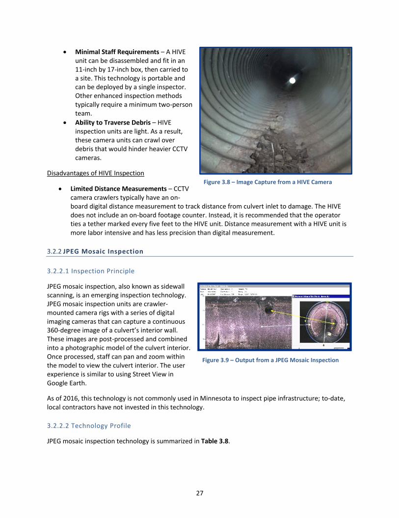
27
Minimal Staff Requirements – A HIVE unit can be disassembled and fit in an 11-inch by 17-inch box, then carried to a site. This technology is portable and can be deployed by a single inspector. Other enhanced inspection methods typically require a minimum two-person team.
Ability to Traverse Debris – HIVE inspection units are light. As a result, these camera units can crawl over debris that would hinder heavier CCTV cameras.
Disadvantages of HIVE Inspection
Limited Distance Measurements – CCTV camera crawlers typically have an on-board digital distance measurement to track distance from culvert inlet to damage. The HIVE does not include an on-board footage counter. Instead, it is recommended that the operator ties a tether marked every five feet to the HIVE unit. Distance measurement with a HIVE unit is more labor intensive and has less precision than digital measurement.
3.2.2 JPEG Mosaic Inspection
3.2.2.1 Inspection Principle
JPEG mosaic inspection, also known as sidewall scanning, is an emerging inspection technology. JPEG mosaic inspection units are crawler-mounted camera rigs with a series of digital imaging cameras that can capture a continuous 360-degree image of a culvert’s interior wall. These images are post-processed and combined into a photographic model of the culvert interior.Once processed, staff can pan and zoom within the model to view the culvert interior. The user experience is similar to using Street View in Google Earth.
As of 2016, this technology is not commonly usedlocal contractors have not invested in this techno
3.2.2.2 Technology Profile
JPEG mosaic inspection technology is summarize
l
d
in Minnesota to inspect pipe infrastructure; to-date, ogy.
in Table 3.8.
Figure 3.8 – Image Capture from a HIVE Camera
Figure 3.9 – Output from a JPEG Mosaic Inspection

28
Table 3.8 – JPEG Mosaic Inspection Considerations
Application Considerations
Planning Phase
Access
JPEG mosaic inspections are deployed from the back of a truck. Culverts to inspect must be accessible by vehicle.
Inspection units are rated for a minimum and maximum diameter. Consider culvert size prior to selecting an inspection unit.
Pre-Cleaning Crawlers can travel over light debris but can get stuck in heavy debris.
Permitting Lane closure permits may be required to access the site.
Inspection Extents JPEG mosaic inspections are limited by culvert size. Contact inspection
contractors to diameter limits for this technology.
Implementation Phase
Staff Count 2 inspectors.
Inspector Skills Training in culvert inspection criteria, software and inspection techniques.
Crawler and inspection software operation. JPEG mosaic data post-processing.
Inspector Equipment
Personal protective equipment. JPEG mosaic camera mounted on an inspection crawler. Camera calibration equipment (e.g., measuring tape, video image
calibration).
Inspection Speed 300 feet of inspection per 10 minutes (30 fpm).
Cost per Inspection In 2016, contractors did not offer this technology in Minnesota. Local
pricing could not be obtained.
Data Evaluation Phase
Data Format Inspection video (*.mpeg). JPEG mosaic model.
Information Obtained from Evaluation
Location of internal culvert damage. Measurable dimensions for culvert damage.
Storage Considerations Inspection video between 600 MB and 800 MB. Size depends on length of
culvert and length of inspection video. JPEG mosaic models are up to 3 GB. Size depends on length of inspection
Note: Local contractors currently do not offer JPEG mosaic inspection services. This is an emerging technology in Minnesota. Data presented in this table is based on limited local experience.
3.2.2.3 Equipment Calibration
JPEG mosaic inspection equipment are calibrated prior to mobilization.
3.2.2.4 Advantages and Disadvantages
Advantages and disadvantages of JPEG mosaic inspection are as follows.
Advantages of JPEG Mosaic Inspection
Detailed Documentation for Office-Based Evaluation – Most enhanced inspection technologies require an inspection team to collect all pertinent data when conducting the inspection. For

29
example, a CCTV camera operator must collect enough video documentation to assist office-based staff in making decisions. If insufficient video documentation is recorded, another field inspection needs to be conducted. JPEG mosaic inspection creates a model of the culvert interior. Office-based staff can pan, zoom, and measure defects to fully documents condition.
Disadvantages of JPEG Mosaic Inspection
Emerging Technology – JPEG mosaic inspection is currently not common in Minnesota. Out-of-state contractors would need to be retained to conduct this type of enhanced inspection. As a result, the mobilization cost for this work may not be cost-effective.

30
CHAPTER 4: ENHANCED INSPECTION TECHNOLOGY SELECTION
When planning for an inspection, it is a best practice to define site limitations and data needs. Once these key project drivers are defined, one should then select the lowest cost inspection method that can successfully collect the required data that is needed. If minimal quantitative data is required from the inspection, one should consider a low-cost end-of-pipe inspection. Enhanced inspection technologies should be considered if precise measurements are required or thorough visual documentation is useful.
Figure 4.1 presents a decision tree that can be used to assist a user in determining whether enhanced inspection technologies should be considered. Decision nodes in this figure will direct a user to lower-cost inspection methods based on site constraints and data needs.
4.1 SELECTION BY INSPECTION TYPE
As discussed in Section 1.3.3, MnDOT implements four types of culvert inspections: design-related, post-construction, condition assessments, and emergency/complaint-related. The type of inspection can drive a technology selection; not all technologies are applicable for all types of inspection.
Table 4.1 presents a summary of common inspection technologies used for different types of inspections.
Table 4.1 – Applicable Technologies by Inspection Type
Purpose of Inspection
Culvert Material
Concrete / Reinforced Concrete
Metal (CMP) Plastic (HDPE, PVC)
Design-Related
Visual
Multi-Sensor
Hammer Sound
Core Sample
CCTV / HIVE
JPEG Mosaic
Visual
Multi-Sensor
CCTV / HIVE
JPEG Mosaic
Visual
Multi-Sensor
CCTV / HIVE
JPEG Mosaic
Post-Construction
Visual
Multi-Sensor
CCTV / HIVE
Visual
Multi-Sensor
CCTV / HIVE
Visual
Multi-Sensor
Mandrel
CCTV / HIVE
Condition Assessment
Visual
Probe Invert w/ Rod
Multi-Sensor
Hammer Sound
Core Sample
CCTV / HIVE
JPEG Mosaic
Visual
Probe Invert w/ Rod
Multi-Sensor
CCTV / HIVE
JPEG Mosaic
Visual
Multi-Sensor
Mandrel
CCTV / HIVE
JPEG Mosaic
Emergency / Complaint Related
Visual
Multi-Sensor
CCTV / HIVE
Visual
Multi-Sensor
CCTV / HIVE
Visual
Multi-Sensor
CCTV / HIVE
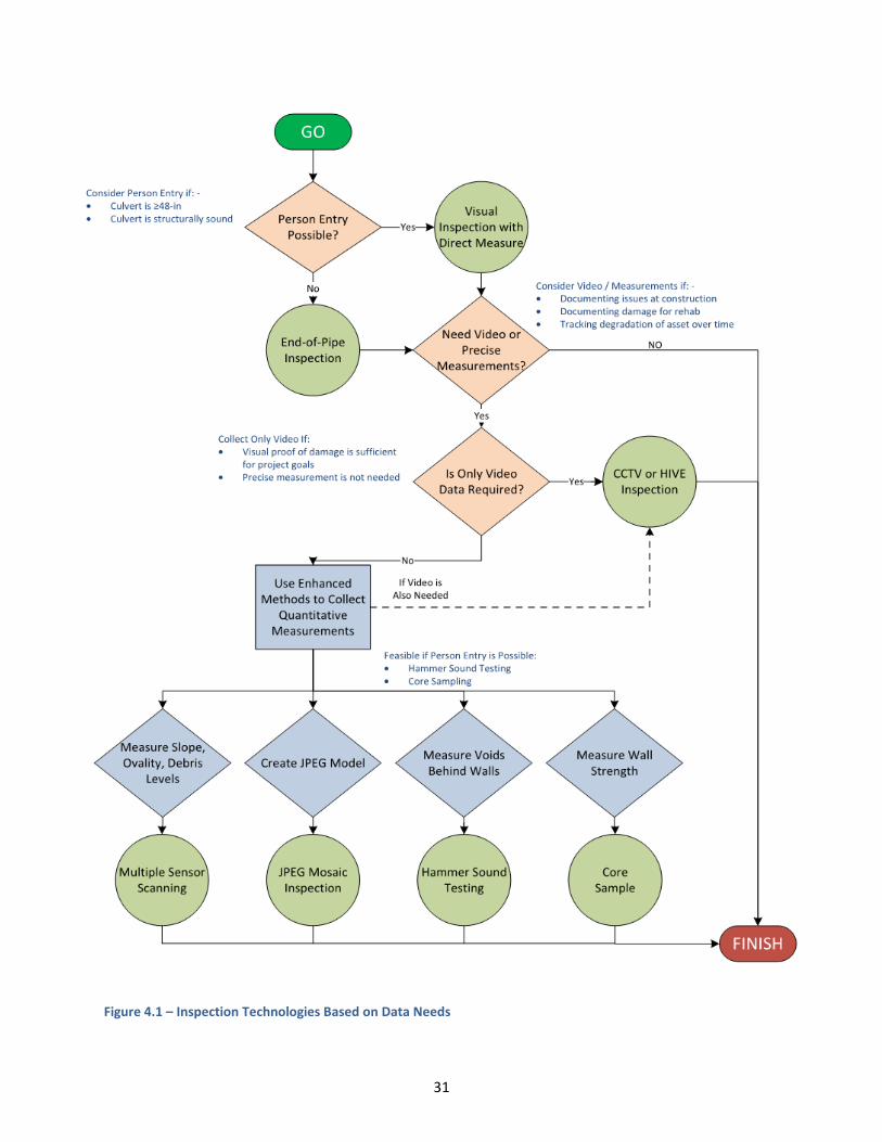
31
Figure 4.1 – Inspection Technologies Based on Data Needs

32
4.2 SELECTION BY SUSPECTED DAMAGE
Different enhanced inspection technologies are better suited for identifying and documenting different types of culvert damage. For example, if a culvert was screened using an end-of-pipe inspection and corrosion is observed, an enhanced inspection should be conducted to document and measure damage; some technologies are suitable (e.g., CCTV) while other are not applicable (e.g., core sampling).
Table 4.2 presents a summary of 10 types of damage commonly observed in culverts. The table lists technologies that can detect and measure each type of damage and identifies the technologies’ limitations. Technologies are ordered from lowest cost to highest cost.

33
Table 4.2 – Applicable Inspection Technologies to Identify and Measure Common Types of Culvert Damage
Type of Damage
Applicable Pipe Materials
Applicable Inspection Methods
Applicable Data Obtained
Typical Unit Cost Technology Limitations and
Constraints
Collapse Concrete
CMP
Reinforced Concrete
End-of-Pipe Identify collapse $0.09 per foot Difficult to see inside pipe beyond 30 feet from inlet.
HIVE Identify collapse $0.23 per foot No limitations.
CCTV Identify collapse $0.23 per foot (MnDOT Resources); $1.00 - $3.00 per foot (Contractor)
No limitations.
Laser Scan Identify collapse $6.50 per foot + $8,500 mobilization
High mobilization cost, processing time.
Corrosion CMP
Reinforced Concrete
End-of-Pipe Identify interior surface corrosion
$0.09 per foot Difficult to see inside pipe beyond 30 feet from outlet. Difficult to measure extent.
HIVE Identify interior surface corrosion
$0.23 per foot Must estimate dimensions of corroded area from camera image.
CCTV Identify interior surface corrosion
$0.23 per foot (MnDOT Resources); $1.00 - $3.00 per foot (Contractor)
Must estimate dimensions of corroded area from camera image.
Hammer Sound Identify rebar corrosion inside pipe wall
$0.44 per foot Only identifies corrosion of concrete reinforcement.
Laser Scan Quantify degradation due to corrosion to 0.1% resolution
$6.50 per foot + $8,500 mobilization
High mobilization cost, processing time.
Cracks / Fractures
CMP
Concrete
Reinforced Concrete
End-of-Pipe Identify cracks / fractures and measure damage within arm’s reach
$0.09 per foot Direct measurement of length, width and depth possible if inspector can reach the crack.
HIVE Identify cracks / fractures. Estimate length and width from video image.
$0.23 per foot Measurement of damage length and width must be estimated from video imagery.
CCTV Identify cracks / fractures. Estimate
$0.23 per foot (MnDOT Resources); $1.00 - $3.00 per foot (Contractor)
Measurement of damage length and width must be estimated from video imagery.

34
Type of Damage
Applicable Pipe Materials
Applicable Inspection Methods
Applicable Data Obtained
Typical Unit Cost Technology Limitations and
Constraints
length and width from video image.
Laser Scan Identify damage and obtain length, width and depth measurements if there is depth to the fracture.
$6.50 per foot + $8,500 mobilization
If the wall surface is split (i.e., fractured), it is possible to map the length, width and depth of damage with laser profiling.
Debris / Sediment
CMP
Concrete
Plastic
Reinforced Concrete
End-of-Pipe Observe debris and sediment to assess depth of debris in culvert to a 10% resolution.
$0.09 per foot Provides estimation of debris levels. Cannot measure debris below the water line. Difficult to view beyond 30 feet from the culvert inlet.
HIVE Observe debris and sediment to assess depth of debris in culvert to a 10% resolution.
$0.23 per foot Provides estimation of debris levels. Cannot measure debris below the water line.
CCTV Observe debris and sediment to assess depth of debris in culvert to a 10% resolution.
$0.23 per foot (MnDOT Resources); $1.00 - $3.00 per foot (Contractor)
Provides estimation of debris levels. Cannot measure debris below the water line.
Laser Scan Measure debris and sediment to 0.1% resolution
$6.50 per foot + $8,500 mobilization
High mobilization cost and processing time. Cannot measure debris below the water line.
Sonar Measure debris below the water line to 0.1% resolution
$6.50 per foot + $8,500 mobilization
(If done with laser scan, total cost is $10.00 per foot + $8.500 mobilization)
Measure debris below water level.
Deformations CMP
Plastic
End-of-Pipe Identification of deformations to a 10% resolution
$0.09 per foot Person entry required to measure diameter. Accuracy limitations with manual measurement.
HIVE Identification of deformations to a 10% resolution
$0.23 per foot No measurement is possible. One can only view the interior for major deformations.

35
Type of Damage
Applicable Pipe Materials
Applicable Inspection Methods
Applicable Data Obtained
Typical Unit Cost Technology Limitations and
Constraints
CCTV Identification of deformations to a 10% resolution
$0.23 per foot (MnDOT Resources); $1.00 - $3.00 per foot (Contractor)
No measurement is possible. One can only view the interior for major deformations.
Mandrel Measurement of deformations exceeding calibrated value
Included as part of acceptance testing
Pass/fail test, no quantification of deformation.
Laser Scan Measurement of deformations to 0.1% resolution
$6.50 per foot + $8,500 mobilization
High mobilization cost and processing time.
Infiltration CMP
Concrete
Plastic
Reinforced Concrete
End-of-Pipe Identify infiltration $0.09 per foot Difficult to view infiltration deep inside a culvert.
HIVE Identify infiltration $0.23 per foot No limitations.
CCTV Identify infiltration $0.23 per foot (MnDOT Resources); $1.00 - $3.00 per foot (Contractor)
No limitations.
Liner Integrity
CIPP Lined Pipe
Concrete Lined Pipe
Epoxy Lined Pipe
End-of-Pipe Identification of degraded liner.
$0.09 per foot Difficult to view liner condition more than 30 feet from the culvert inlet.
HIVE Identification of degraded liner.
$0.23 per foot Does not provide a quantified measurement of liner degradation.
CCTV Identification of degraded liner.
$0.23 per foot (MnDOT Resources); $1.00 - $3.00 per foot (Contractor)
Does not provide a quantified measurement of liner degradation.
Laser Scan Measurement of concrete liner spalling and impact to cross section area.
$6.50 per foot + $8,500 mobilization
High mobilization cost and processing time.
Offset Concrete Joints
Concrete
Reinforced Concrete
Plastic
End-of-Pipe Identification of split laterals.
$0.09 per foot Difficult to view joint condition more than 30 feet from the culvert inlet. Difficult to view joints that are split laterally.

36
Type of Damage
Applicable Pipe Materials
Applicable Inspection Methods
Applicable Data Obtained
Typical Unit Cost Technology Limitations and
Constraints
HIVE Estimate of lateral and perpendicular offset distances.
$0.23 per foot Offset dimensions must be estimated from video imagery.
CCTV Estimate of lateral and perpendicular offset distances.
$0.23 per foot (MnDOT Resources); $1.00 - $3.00 per foot (Contractor)
Offset dimensions must be estimated from video imagery.
Laser Scan Measurement of lateral offset to a 0.1% resolution.
$6.50 per foot + $8,500 mobilization
High mobilization cost and processing time.
Roots CMP
Concrete
Plastic
Reinforced Concrete
End-of-Pipe Identification of intruding roots.
$0.09 per foot Difficult to view smaller roots if roots are more than 30 feet from the culvert inlet.
HIVE Identification of intruding roots.
$0.23 per foot No limitations.
CCTV Identification of intruding roots.
$0.23 per foot (MnDOT Resources); $1.00 - $3.00 per foot (Contractor)
No limitations.
Sags CMP
Concrete
Plastic
Reinforced Concrete
End-of-Pipe Identifying sags near the culvert inlets may be possible if one can see the bottom of the culvert.
$0.09 per foot Limited ability to recognize sags.
HIVE Identification of sags based on observing change in water level as the camera proceeds down a culvert.
$0.23 per foot Camera may become submerged if a severe sag is encountered.
CCTV Identification of sags based on observing change in water level as the camera proceeds down a culvert.
$0.23 per foot (MnDOT Resources); $1.00 - $3.00 per foot (Contractor)
Camera may become submerged if a severe sag is encountered.
Inclinometer Invert slope as a percentage
$6.50 per foot + $8,500 mobilization (If associated with multi-sensor inspection)
Accuracy may be limited when crawler goes underwater and

37
Type of Damage
Applicable Pipe Materials
Applicable Inspection Methods
Applicable Data Obtained
Typical Unit Cost Technology Limitations and
Constraints
buoyance or invert condition may impact slope measurements.
Holes Visible from Inside a Culvert
CMP
Concrete
Plastic
Reinforced Concrete
End-of-Pipe Location of voids that are visible from end the culvert
$0.09 per foot It is difficult to see the extent of voids from culvert ends. Voids within the first few feet of the culvert could be quantified.
CCTV Identification of voids visible while camera inspecting the culvert.
$0.23 per foot (MnDOT Resources); $1.00 - $3.00 per foot
Camera inspection often does not capture the depth of void.
Laser Scan Location and depth of voids.
$6.50 per foot + $8,500 mobilization
High mobilization cost and data processing time.
Notes:
Refer to tables in Section 3 for assumptions used when assigning unit costs for each inspection. Costs were developed in 2016. 2016 Construction Cost Index per the Engineering News Record is 10338.
Costs are presented assuming equipment costs are sunk and not considered when selecting an inspection technology. Refer to Table ES.1 for estimated equipment costs.

38
CHAPTER 5: BEST PRACTICES
One can conceptually divide the inspection process into four phases: the planning phase, the implementation phase, the data evaluation phase, and the project closeout phase. While it is not mandatory to follow these phases for all projects, this phased concept provides a useful framework for discussing best practices in this guidance document.
5.1 PLANNING PHASE
Planning is the first phase of an enhanced inspection project. Goals of the planning phase are to:
Review existing data.
Review site to identify site constraints that will impact an inspection.
Identify inspection methods/scope.
Complete pre-inspection work (e.g., cleaning, safety procedures).
Conduct pre-inspection checks on inspection equipment.
5.1.1 Review of Existing Data Figure 5.1 – HydInfra Software Interface
The first step when planning for an inspection is to collect and review available background information on the project area and culvert. Background information includes existing site maps, as-built drawings, historic digital videos, and HydInfra database information (Figure 5.1). Note site conflicts and existing damage.
5.1.2 Preliminary Site Inspection
Review the site and note features that may impact implementation of an inspection. The following questions will be answered after this site review: What Site Conditions Impact Access to the
Culvert?
How will the inspection team access the site? · Culvert outlet submerged
Is access possible at both ends of the culvert? · Culvert inlet flooded due to seasonal or
Is a better view of the culvert possible if the inspection storm-related water
is done at a specific time of day? A different season? · Vegetation overgrowth
Proximity to busy roads In dry weather? ·
· Access through private property Does access need to be constructed to reach the site · Steep slope/large drop to the culvert
by vehicle? · Animals/vermin/insects
Are flow controls needed to dewater the culvert and inspect?
Are traffic controls required? Do lanes need to be temporarily closed to access the site?
39
What are specific safety requirements? What types of personal protective equipment are needed?
Are there large debris and sediment deposits in the culvert? Does the culvert need to be cleaned prior to inspection?
Does brush need to be cleared to reach the site by person or vehicle?
Is location data, GIS data, and/or coordinates accurate?
Site constraints that will impact the inspection team’s ability to complete an inspection should be noted. These constraints will be addressed or stated when establishing project scope.
5.1.3 Define Inspection Scope
If applicable to the work, and after existing data and site conditions have been reviewed, define the inspection scope. Scope should be communicated to establish the inspection team’s objectives.
Note if an enhanced inspection is required for construction acceptance, the inspection scope will be defined and communicated to the contractor in the construction specifications.
5.1.4 Procure Inspection Services
Next, inspection services will be procured. Inspection services may be provided by MnDOT staff or contracted.
If the inspection is conducted by MnDOT staff, schedule pre-inspection work (e.g., cleaning, site clearing), schedule staff to conduct the inspection, and reserve inspection equipment.
If the inspection is conducted by outside contractors, the contract will explicitly define site constraints, assumptions, quantities of work to complete, deliverable expectations, and schedule. Schedule pre-inspection work and schedule MnDOT staff to act as field representative/points of contact.
5.1.5 Complete Pre-Inspection Work
The project schedule will be set to give MnDOT staff and/or the contractor enough time to complete pre-inspection work prior to mobilization. Tasks that must be completed include:
Review and confirm submission of applicable permits. Permits may include, but are not limited to, permit-required confined space access, private property access, and lane closure permits.
How Clean is Clean when Conducting a Culvert Inspection?
The Pipe Assessment Certification Program (PACP) recommends cleaning a pipe to restore 95 percent or more of the cross-sectional area before conducting a video inspection. If this level of cleaning is not practical, one should assure the culvert walls are clean enough to allow unobstructed views of the walls and invert.
Thorough cleaning of a storm culvert may not be possible. One should aim to clean the pipe to have a maximum of 5 percent debris at the invert. Inspectors should note debris levels and recognize that full inspection of an invert may not always be feasible.
The pipe must be cleaned and free from deposits and encrustations before conducting a mandrel test. Hard deposits may falsely show that a culvert is excessively deformed.
What Type of Information Defined Inspection Scope?
· Type of data needed from the inspection (e.g., video files, laser profile)? · Inspection technology that is cost-effective to obtain this data? · Pre-inspection work is required prior to mobilization? Cleaning? Site clearing and grubbing? · Permits are required?
· Will this work be conducted with MnDOT resources or with contractor labor? · Quantity of work to complete (e.g., CCTV 1,000 lf of 24-inch CMP culvert)? · Detailed site map showing the culvert, adjacent roads, and site constraints. · Relevant known culvert damage identified from old videos, HydInfra data, or the site visit? · Personal protective equipment.
· Certifications.

40
Clear brush at the site as required for access.
Remove sediment and deposits from the culvert as required for inspection.
5.1.6 Conduct Pre-Inspection Checks on Inspection Equipment
Regardless of the inspection method, the inspection team should meet to discuss expectations. At this meeting, discuss deliverables, quality expectations, and site restoration.
The inspection team will then confirm inspection equipment is functioning properly and measuring accurately. Considerations for specific inspection technology includes:
Inspections Requiring Person Entry (Visual, Hammer Sound, Core Sampling, Direct Measurement) – Check safety equipment and review confined space safety protocols. Confirm lighting is adequate for safe passage through the culvert.
Multiple Sensor Inspections – Confirm the crawler can fully maneuver. Confirm sensors are calibrated. Verify that on-board footage counters are set to ‘0’ feet at the inlet of the culvert.
Mandrel Inspections – Confirm the mandrel onsite is calibrated for the size of the culvert. Confirm the interior of the culvert has been cleaned.
CCTV Camera Inspection – Confirm the crawler can fully maneuver. Confirm the video camera is transmitting and recording an image. Confirm the video image is calibrated and corrected for color. Verify that on-board footage counters are set to ‘0’ feet at the inlet of the culvert. Verify that lighting is sufficient to provide a good recorded image in the culvert.
HIVE Inspection – Confirm the HIVE unit can fully maneuver. Confirm the video camera is transmitting and recording an image. Verify that lighting is sufficient to provide a good recorded image in the culvert.
5.2 IMPLEMENTATION PHASE
The implementation phase starts when the inspection team begins the inspection. This phase is finished when all onsite work, including site restoration, is satisfactorily completed in accordance with MnDOT’s requirements.
Refer to the following sections for step-by-step best practices for implantation of each type of inspection. Note that the individual responsible for completing each step depends on whether MnDOT conducts the work using MnDOT staff or retains an inspection contractor. In general, the person conducting each step is the one collecting inspection data.
What Can Be Done to Improve CCTV Camera Lighting in a Culvert?
A culvert inspection can be negatively impacted by sunlight shining into and through the culvert. When the camera lens is directed at the sun, the video will be obscured by lens flare.
To remedy this, the inspector should attach a heavy tarp to the outlet. This tarp will block sunlight. The inspector can then control light in the culvert with the crawler’s on-board lights.
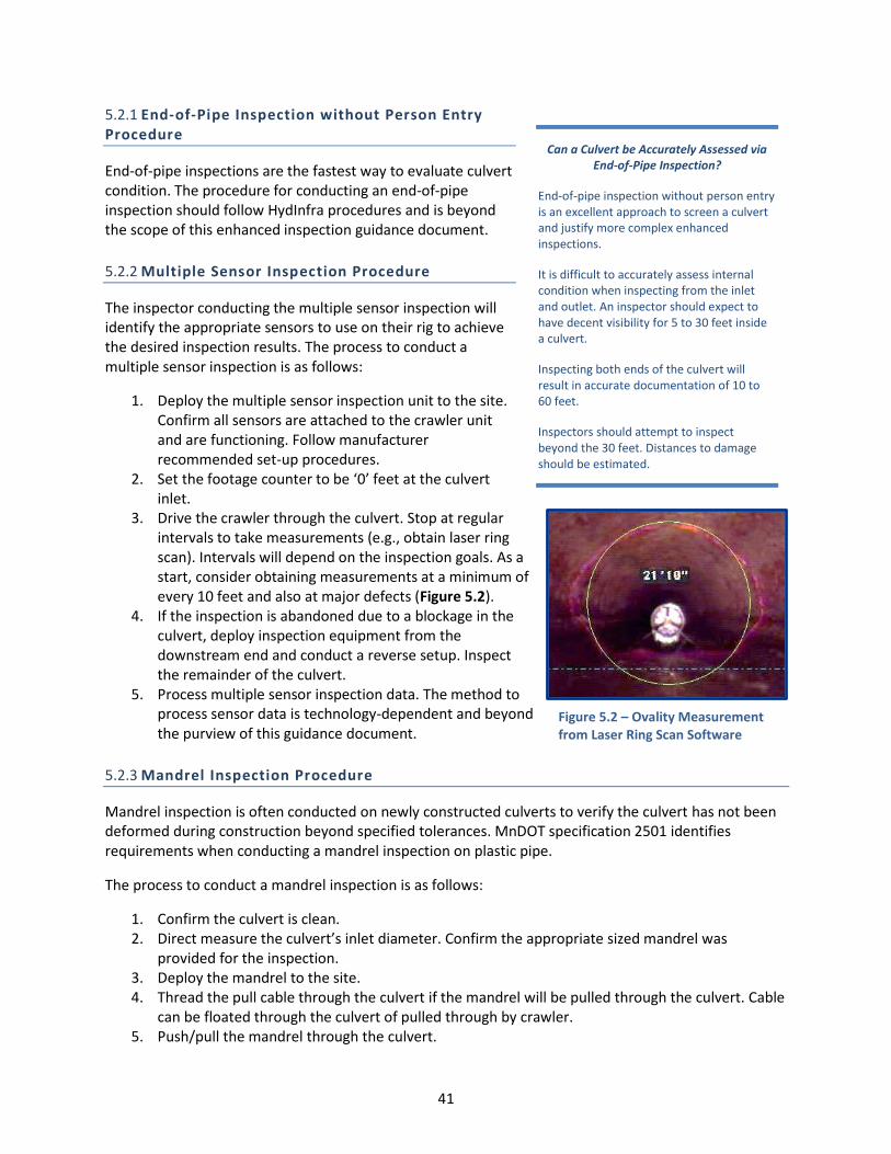
5.2.1 End-of-Pipe Inspection without Person Entry Procedure
End-of-pipe inspections are the fastest way to evaluate culvert condition. The procedure for conducting an end-of-pipe inspection should follow HydInfra procedures and is beyond the scope of this enhanced inspection guidance document.
5.2.2 Multiple Sensor Inspection Procedure
The inspector conducting the multiple sensor inspection will identify the appropriate sensors to use on their rig to achieve the desired inspection results. The process to conduct a multiple sensor inspection is as follows:
1. Deploy the multiple sensor inspection unit to the site. Confirm all sensors are attached to the crawler unit and are functioning. Follow manufacturer recommended set-up procedures.
2. Set the footage counter to be ‘0’ feet at the culvert inlet.
3. Drive the crawler through the culvert. Stop at regular intervals to take measurements (e.g., obtain laser ring scan). Intervals will depend on the inspection goals. As a start, consider obtaining measurements at a minimum of every 10 feet and also at major defects (Figure 5.2).
4. If the inspection is abandoned due to a blockage in the culvert, deploy inspection equipment from the downstream end and conduct a reverse setup. Inspect the remainder of the culvert.
5. Process multiple sensor inspection data. The method to process sensor data is technology-dependent and beyond the purview of this guidance document.
Can a Culvert be Accurately Assessed via End-of-Pipe Inspection?
End-of-pipe inspection without person entry is an excellent approach to screen a culvert and justify more complex enhanced inspections.
It is difficult to accurately assess internal condition when inspecting from the inlet and outlet. An inspector should expect to have decent visibility for 5 to 30 feet inside a culvert.
Inspecting both ends of the culvert will result in accurate documentation of 10 to 60 feet.
Inspectors should attempt to inspect beyond the 30 feet. Distances to damage should be estimated.
5.2.3 Mandrel Inspection Procedure
Mandrel inspection is often conducted on newly constructed culverts to verify the culvert has not been deformed during construction beyond specified tolerances. MnDOT specification 2501 identifies requirements when conducting a mandrel inspection on plastic pipe.
The process to conduct a mandrel inspection is as follows:
1. Confirm the culvert is clean. 2. Direct measure the culvert’s inlet diameter. Confirm the appropriate sized mandrel was
provided for the inspection. 3. Deploy the mandrel to the site. 4. Thread the pull cable through the culvert if the mandrel will be pulled through the culvert. Cable
can be floated through the culvert of pulled through by crawler. 5. Push/pull the mandrel through the culvert.
41
Figure 5.2 – Ovality Measurement from Laser Ring Scan Software

42
6. Identify location where the culvert deflects beyond the tolerance of the mandrel or more than 5 percent deflection. Typically, when a culvert fails the mandrel test, the culvert will be removed and reconstructed.
7. If the mandrel results conclude that the culvert is significantly deflected, take additional photographs and measurements before the mandrel is removed from the site. This documentation is particularly important if the mandrel test is used as a basis for rejecting new construction.
5.2.4 Hammer Sound Testing Procedure (Person Entry Facilitated)
Person entry is required when one conducts hammer sound testing. This test is often conducted concurrently with a visual inspection inside the culvert. The inspection process is as follows:
1. Conduct a site assessment to determine whether the culvert is a permit-required confined space. Refer to MnDOT confined space entry procedures as appropriate.
2. Stop at regular intervals to conduct the hammer sound test. Consider obtaining measurements every 10 feet and at major defects. If many voids are observed behind the culvert wall, increase the inspection frequency. Note that the presence of groundwater behind the culvert wall may result in false identification of voids. It is good practice to take many hammer sound measurements around suspected voids. If the void appears to be unusually large, consider whether groundwater is impacting results.
3. Record distance from the inlet for each hammer test point.
4. Strike the culvert wall at the 12 o’clock, 3 o’clock, 6 o’clock, and 9 o’clock position (Figure 5.3). If there is water in the culvert, it may not be possible to inspect the culvert at the 6 o’clock position. Note areas where the hammer strike sounds hollow. Document results of the test. If hollow areas are detected, conduct additional hammer strikes to estimate the boundaries of voids behind the culvert wall.
5.2.5 Core Sampling Concrete Culverts Procedure (Person Entry Facilitated)
Person entry is required when conducting a core sample test. The inspection team will need to enter the culvert to cut a core sample and to patch the sample point. The core sampling process is as follows:
1. Conduct a site assessment to determine whether the culvert is a permit-required confined space. Refer to MnDOT confined space entry procedures as appropriate.
2. Radar or metal detection means can be used to locate steel reinforcement in potential sample locations.
3. Cut a core sample from the culvert wall. 4. Patch the sample point with grout.
Figure 5.3 – Hammer Sound Testing

43
5. Conduct laboratory testing on the core sample. Testing should include compressive strength testing in accordance with ASTM C39 – Standard Test Method for Compressive Strength of Cylindrical Concrete Specimens.
5.2.6 Closed Circuit Television Inspection Procedure
Several organizations have published best practices when conducting CCTV camera inspections. The General Approach to TV Inspection Using PACP published in the Pipeline Assessment Certification Program Reference Manual (NASSCO, 2015) contains a thorough list of best practices. These best practices are incorporated into the procedure below:
1. Deploy the CCTV camera to the site. Follow manufacturer recommended set-up procedures.
2. Confirm on-board video cameras and lighting are functional and pan/tilt as expected.
3. Clean the camera lens and confirm no grease or streaking is present. Not if the camera or lens is obscured by water or grease during an inspection, it is a best practice to remove the camera, clean the lens, and resume the inspection.
4. Set the footage counter to be ‘0’ feet at the start of the culvert (Figure 5.4).
5. Set the camera lens to have a focal point centered in the culvert. NASSCO best practices recommend the
camera is positioned within ± 10 percent of the center of the culvert.
6. Drive the crawler through the culvert at a speed no faster than 30 feet per minute.
7. Stop completely at damage or construction features in the culvert. Allow the camera lens to focus on the damage. Use the camera’s pan, tilt, zoom, and/or light adjustment functions to fully document damage.
8. If inspection software is used, assign the appropriate defect code using the software’s dropdown menus to document the observed damage.
9. Record notes or observations that provide context to the video image.
10. If the inspection is abandoned due to a blockage in the culvert, deploy inspection equipment from the downstream end and conduct a reverse setup. Inspect the remainder of the culvert.
11. If the inspection is abandoned due to a blockage in the culvert, deploy inspection equipment from the downstream end and conduct a reverse setup. Inspect the remainder of the culvert.
Figure 5.4 – Footage Counter on a CCTV Camera Screen
How Can One Best Protect Expensive Camera Equipment from Hazardous
Culvert Conditions?
Culvert conditions such as steep slopes, sags with deep water, and partial collapses are often too risky to conduct a person entry inspection. Cameras are excellent tools to inspect these high-risk areas.
The camera operator should take measures to protect their camera. If the inspection is on a steep slope, travels below partially collapsed culvert, or through deep water, a good practice is to tie a retrieval tether to the camera.
44
5.2.7 HIVE Inspection Procedure
The HIVE inspection unit is a tool developed by MnDOT as a method to video inspect culverts. Best practices applicable to CCTV camera inspections also apply to conducting a HIVE inspection.
Steps to conduct a HIVE inspection are as follows:
1. Deploy the HIVE inspection unit to the site. 2. Confirm on-board video cameras and lighting are functional. 3. Clean the camera and confirm no grease or streaking is on the lens. 4. Drive the crawler through the culvert and target a speed no faster than 30 feet per minute. 5. Stop completely at damage or construction features in the culvert. Allow the camera lens to
focus on the damage. 6. Record notes or observations that provide context to the video image. 7. If the inspection is abandoned due to a blockage in the culvert, deploy inspection equipment
from the downstream end and conduct a reverse setup. Inspect the remainder of the culvert. Immediately notify maintenance staff of the blockage.
8. Process video inspection data and submit for quality review and evaluation.
5.2.8 JPEG Mosaic Inspection Procedure
Best practices to conduct JPEG mosaic inspection are as follows:
1. Deploy the JPEG mosaic inspection unit to the site. Follow manufacturer recommended setup procedures.
2. Confirm on-board cameras and lighting are functional. 3. Set the footage counter to be ‘0’ feet at the culvert inlet. 4. Drive the crawler through the culvert. Record JPEG imagery at intervals required by the camera
unit. 5. If the inspection is abandoned due to a blockage in the culvert, deploy inspection equipment
from the downstream end and conduct a reverse setup. Inspect the remainder of the culvert. Immediately notify maintenance staff of the blockage.
6. Process JPEG mosaic inspection data. The method to process sensor data is technology-dependent and beyond the purview of this guidance document.
Restore Site
After inspection work is complete, the inspection team is to restore the site to its pre-inspection condition. Prior to completing the inspection phase, MnDOT representatives should review the site to confirm that vehicles have not damaged the site when deploying inspection equipment. If damage, such as tire tread marks, are observed, restore the site per MnDOT specifications.
5.3 DATA EVALUATION PHASE
After field work is complete, confirm data meets quality expectations. Quality data will then be evaluated by technical staff and used to support design and asset management decision making.

45
5.3.1 Conduct Data Quality Control Reviews
Review inspection data to confirm that it meets both specification requirements and MnDOT’s expectations on quality. Poor quality data is of no practical use to technical staff. Before an inspection project is closed out, request the inspector corrects quality deficiencies in the inspection records.
Table 5.1 summarizes quality control checks that should be conducted on data collected by each inspection technology.
Table 5.1 – Quality Control Considerations for Enhanced Inspection
Technology Quality Control Consideration
Multiple Sensor Inspections
Has the entire length of culvert been inspected? Has the reason for abandoning the inspection been documented?
Are sensor results provided in a summary report? Is the report logically organized? Can the data be understood by MnDOT engineers who are unfamiliar with multiple sensor inspection?
Were laser ring measurements recorded at the specified intervals? If special software is required to review sensor data, has this software provided? Is this
software compatible with MnDOT Information Technology (IT) resources? Does the laser ring data report ovality? Does the laser ring data show the location and extent of degraded wall surface and/or wall
deposits? Does sonar scanning results show the location and extent of debris below the water line? Are
debris quantities estimated? Do inclinometer results show the location of sags? Does the inclinometer report the slope of
the culvert?
Mandrel Testing
Has calibration documentation been provided? Does the inspection documentation adequately confirm acceptable ovality?
Hammer Sound Testing
Were hammer sound tests conducted at the specified intervals? Was the entire circumference of the culvert tested? Has the reason for abandoning the inspection been documented?
Are hammer sound test results linked to a location in the culvert (i.e., footage from inlet)? Are hammer sound test results summarized in a report? Can results be understood by MnDOT
engineers who are unfamiliar with hammer sound testing?
Core Sampling
Was core sampling conducted at the specified locations? Is the testing lab certified for core sample tests? Did the inspector provide documentation that the sample location was patched? Are core sample results summarized in a report? Can results be understood by MnDOT
engineers who are unfamiliar with core sampling?
CCTV Camera Inspections
Refer to the section ‘CCTV and HIVE Inspection Quality Control Parameters’ for detailed quality control considerations for CCTV data.
Has the entire length of culvert been inspected? If not, is there an acceptable reason for abandoning the inspection?
Was an inspection summary report provided? Can results be understood by MnDOT engineers who are unfamiliar with CCTV camera inspections?
If specified, did the camera operator assign a defect to damaged areas observed in the culvert?
If specified, are inspection database files provided? Is inspection video provided in a format that can be viewed using software available to MnDOT
(e.g., *.mpeg)?
HIVE Inspections
Refer to the section ‘CCTV Camera Inspection Quality Control Parameters’ as a basis for evaluating video quality. Consider, however, that the video quality and maneuverability of a HIVE inspection unit is limited compared to a CCTV crawler.
Has the entire length of culvert been inspected? If not, is there an acceptable reason for abandoning the inspection?

46
Technology Quality Control Consideration
Was an inspection summary report provided? Can results be understood by MnDOT engineers who are unfamiliar with culvert inspections?
Is inspection video provided in a format that can be viewed using software available to MnDOT (e.g., *.mpeg)?
JPEG Mosaic Inspections
Is the entire length of culvert inspected? If not, is there an acceptable reason for abandoning the inspection?
Special software is required to review JPEG mosaic data. Is this software provided? Is this software compatible with MnDOT Information Technology (IT) resources?
Does the JPEG mosaic model show the internal culvert image at an acceptable resolution?
5.3.2 CCTV and HIVE Inspection Video Quality Control Parameters
The quality of a video-based inspection depends on the quality of the image that is recorded during the inspection. Review inspection video to confirm it meets the following ten quality components:
1. Video Quality – NASSCO recommends that inspections are recorded in color and at a minimum aspect of 650 x 480 pixels. While high-quality video imagery is not essential to a pipe inspection, contractors should ideally provide digital video that is on par with DVD imagery. A reviewer can determine the aspect ratio used to record a video by right-clicking on the video file, selecting properties, selecting the details tab and then reviewing ‘Frame Width’ and ‘Frame Height’.
Always consider local contractor’s technology limitations. If digital inspection cameras are not available in the region, consider whether lesser quality imagery is acceptable.
2. Color Quality – Maintaining true color is important when inspecting joints for discoloration and mineral deposits. If color is poor (i.e., too saturated, poor contrast), the inspector should adjust settings on the camera.
A reviewer will need to use their best judgement when assessing color quality. If one cannot see a color difference at pipe joints, it is likely that the image is too saturated or recorded with poor contrast. A reviewer may be able to adjust image color using a desktop media player and adjusting video settings such as ‘Hue’, ‘Saturation’ and ‘Contrast’.
3. Lens Condition – The camera lens should remain clean throughout the entire inspection. If debris, grease or water obscures the lens, the inspector should clean the lens and re-inspect.
If the lens is obscured during an inspection and not cleaned, a reviewer should determine if the grease / water is severe enough to prevent one from identifying issues in the culvert. If so, lens condition is poor.
4. Lighting Condition – The camera unit should include lighting that is appropriate for the culvert size. Lighting should fully illuminate the entire culvert, but not over illuminate. Poor lighting will prevent the inspector from viewing the culvert’s
Figure 5.5 – CCTV Image with Too Much Light

47
crown condition. Over-lighting will wash out small damage on the culvert walls (Figure 5.5). Under lighting will prevent an inspector from identifying all damage.
A reviewer will need to use their judgement when assessing lighting during the inspection. If one cannot see wall texture, it is likely that the image is either under or over-light. A reviewer may be able to adjust lighting using a desktop media player and adjusting video settings such as ‘Brightness, and ‘Contrast’.
5. Centered View – The camera should be placed in the proper horizontal and vertical position to prevent image distortion. If the camera is not centered down the culvert, the image will be distorted (Figure 5.6).
If the image is not centered, a reviewer should identify whether the image is distorted and it is difficult to accurately view the culvert’s cross sectional shape.
6. Footage Counter Accuracy – The CCTV crawler should have a digital footage counter. This footage counter should start at ‘0’ feet at the start of the inspection. If the counter is not set at ‘0’ feet, one cannot correlate damage in the culvert to above grade issues.
Note that the HIVE inspection unit does not have a digital footage counter. This criterion is not applicable when evaluating HIVE inspection video.
7. Inspection Speed – NASSCO recommends that inspections are not conducted at a speed faster than 30 fpm. To assess inspection speed, divide distance traveled per the inspection cameras digital footage counter by the video time.
8. Documentation of Damage – The inspector should stop the camera at damage and use the pan-and-tilt function to fully record the issue. A reviewer should always assume that damage may be been missed. When reviewing inspection video, look for other defects that were not noted by the camera operator.
9. Condition Impacts to Quality – Often, culverts will not be cleaned prior to inspection. If the invert is covered with sediment, it will not be possible to inspect invert condition. Ideally, culverts should be cleaned to an adequate level to allow the camera a full and uninterrupted view of condition.
10. Environmental Factors – Environmental factors, such as water level from rain, active infiltration from antecedent moisture and fog/steam, may impact video quality.
Figure 5.6 – CCTV Image Distortion
Can One Rely on Video of Condition Below the Water Level?
A key principle of inspecting per the PACP is to ‘only code defects that you can see.’ If a CCTV camera can view a degraded invert, this damage should be noted.
An inspector should use caution when viewing culvert condition through deep water. Culvert water is often turbid and difficult to see through. If invert damage is suspected, but cannot be clearly viewed, the inspector should consider damming flow or utilizing other means for flow control.

48
5.3.3 Data Evaluation
The purpose of conducting an enhanced inspection is to collect inspection data that can then be evaluated to support design and asset management decision making. As such, data evaluation is a critical step in the inspecting process.
Best practices for conducting a technical evaluation of inspection data is beyond the scope of this Best Practices Guidance Handbook. General guidance, however, is provided herein and is based on the inspection objectives defined in Section 2.
5.3.3.1 Evaluating Post-Construction Inspection Data
CCTV or HIVE video can be used to record the internal condition of new culverts prior to acceptance. This practice provides documentation of condition that can be used to justify acceptance/rejection of work and also to support warranty claims.
New Construction
Enhanced inspection data is useful in reviewing newly constructed culverts to confirm the culvert meets the construction requirements.
Review field measurements to confirm the culvert length, diameter, and material match the design. Compare field data to design plans.
If an inclinometer was used, review inclinometer data to confirm the culvert’s slope meets the plans. If an inclinometer was not used, review inspection video to confirm there are not sags in the line. Sags are indicative of poor culvert bedding.
Review inspection video to confirm the culvert is not damaged. This review should focus on identifying discolorations, infiltration, cracks, fractures, and separated joints.
Inspection video should be reviewed to confirm the culvert is not deformed beyond construction tolerances (i.e., 5 percent). If deformation cannot be visually confirmed, consider other inspection methods such as a mandrel or laser ring inspection.
Per MnDOT Specification 2501 (2016), new plastic culverts will need to be inspected 30 days after construction to confirm the culvert’s cross-section is not deflected by more than 5 percent (i.e., the cross section is within 95 percent of the design diameter).
Per MnDOT Specification 2501 (2016), plastic culverts that are 24-inch or smaller should be inspected by a nine-point mandrel calibrated to 95 percent of the certified actual mean inner diameter. Culverts that are 30-inch or larger shall be inspected by mandrel or other method.
Other methods include direct measurement or laser ring scanning. Direct measurement, particularly of large diameter culverts, are prone to inspector error. If available, and cost-effective, laser ring scanning provides quantification of culvert ovality.
Post-Lining
Culverts that have either been slip lined or received a cured-in-place pipe (CIPP) liner should be inspected prior to acceptance. Per MnDOT’s CIPP lining special provision S-1.8, CCTV inspection should be conducted for culverts that are 60 feet or longer and after a liner cures and.
What is the Maximum Distance to Reliably Visually Inspect a CIPP Liner?
Inspectors can typically clearly see damage up to 30 feet from each end of a culvert. If a culvert is longer than 60 feet, one should rely on CCTV video to assess the quality of a CIPP lined culvert.
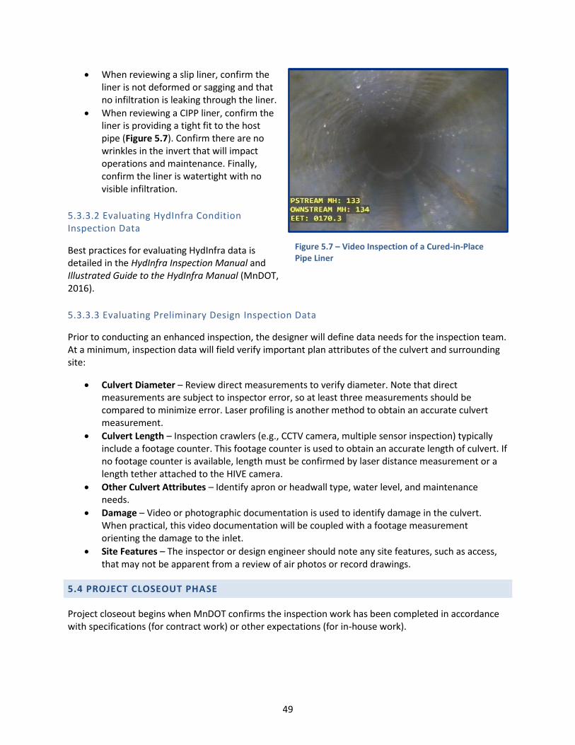
49
When reviewing a slip liner, confirm the liner is not deformed or sagging and that no infiltration is leaking through the liner.
When reviewing a CIPP liner, confirm the liner is providing a tight fit to the host pipe (Figure 5.7). Confirm there are no wrinkles in the invert that will impact operations and maintenance. Finally, confirm the liner is watertight with no visible infiltration.
5.3.3.2 Evaluating HydInfra Condition Inspection Data
Best practices for evaluating HydInfra data is detailed in the HydInfra Inspection Manual and Illustrated Guide to the HydInfra Manual (MnDOT, 2016).
5.3.3.3 Evaluating Preliminary Design Inspection Data
Prior to conducting an enhanced inspection, the designer will define data needs for the inspection team. At a minimum, inspection data will field verify important plan attributes of the culvert and surrounding site:
Culvert Diameter – Review direct measurements to verify diameter. Note that direct measurements are subject to inspector error, so at least three measurements should be compared to minimize error. Laser profiling is another method to obtain an accurate culvert measurement.
Culvert Length – Inspection crawlers (e.g., CCTV camera, multiple sensor inspection) typically include a footage counter. This footage counter is used to obtain an accurate length of culvert. If no footage counter is available, length must be confirmed by laser distance measurement or a length tether attached to the HIVE camera.
Other Culvert Attributes – Identify apron or headwall type, water level, and maintenance needs.
Damage – Video or photographic documentation is used to identify damage in the culvert. When practical, this video documentation will be coupled with a footage measurement orienting the damage to the inlet.
Site Features – The inspector or design engineer should note any site features, such as access, that may not be apparent from a review of air photos or record drawings.
5.4 PROJECT CLOSEOUT PHASE
Project closeout begins when MnDOT confirms the inspection work has been completed in accordance with specifications (for contract work) or other expectations (for in-house work).
Figure 5.7 – Video Inspection of a Cured-in-Place Pipe Liner

50
5.4.1 Closeout Contract
If the inspection work was conducted by a contractor, review inspection deliverables. If the deliverables do not meet specification or are otherwise deficient, notify the contractor prior to closing out the inspection contract. Confirm the following:
Proper locations have been inspected.
Proper documentation is provided.
Required measurements have been taken by methods described in the contract.
Inspection documentation follows standard condition rating criteria.
Proper quality control procedures have been followed.
Data was compared to record, design, or as-built information.
Delivery format and required reporting was submitted.
Follow-up activities are identified.
Site restoration is complete.
No outstanding issues or claims exist between MnDOT, the contractor, utilities, or property owners.
If the contractor met the terms of the contract, the contractor should be paid and the contract will be closed out.
5.4.2 Archive Data
Inspection data is then archived. Inspectors should upload HydInfra inspections to the HydInfra database.
51
CHAPTER 6: COST-EFFECTIVENESS OF ENHANCED INSPECTION
Enhanced inspections are more resource intensive than simple end-of-pipe inspections. When an enhanced inspection is required, MnDOT will need to devote more labor to plan, collect data, and review inspection data. In addition, staff labor required for enhanced inspection or contractor unit costs for enhanced inspections are higher than for end-of-pipe inspection.
Considering the higher cost of enhanced inspection, enhanced inspections are cost-effective when the data collected has clear value to MnDOT.
6.1 RISK AVOIDANCE
The ultimate value of obtaining enhanced inspection data is to provide MnDOT with information that allows the organization to avoid unacceptable risk. Common risks that are mitigated with enhanced inspection data include:
Maintaining a current, detailed record of culvert condition in vulnerable and critical areas can help MnDOT to identify when a culvert has degraded to a point where it is at risk of imminent failure. MnDOT can then choose to rehabilitate this culvert before collapse. MnDOT will then avoid the higher cost of an emergency repair in a critical area of the highway system.
If MnDOT can utilize enhanced inspection data to reject poorly constructed culverts before paving and completing a road construction project, MnDOT can avoid the cost of replacing the culvert early. Instead, the contractor will be obligated to repair or replace the poorly constructed culvert.
Enhanced inspection data are valuable when rejecting work that does not comply with specifications. Recorded and/or measured data for out-of-specification construction can help to avoid contractor conflicts and claims.
It is difficult to fiscally account for risk avoidance. Organizations that were interviewed for this study had difficulty quantifying the cost/benefit of enhanced inspections. Instead, organizations encourage their engineering staff to select enhanced inspections when the inspection proves to be cost-effective. That is, an enhanced inspection is justified when data can help the organization effectively meet goals without surpassing reasonable cost thresholds for the collection of this data. Specific circumstances where enhanced inspections may be cost-effective are discussed in depth herein.
6.2 COST-EFFECTIVENESS CONSIDERATIONS FOR DESIGN-RELATED INSPECTIONS
Culvert inspection during design is often required if the culvert will be rehabilitated. If the culvert is to be rehabilitated, one should conduct an end-of-pipe inspection. If the full-pipe condition cannot be observed from either end, consider conducting a CCTV or HIVE inspection to identify issues that must be addressed in the design documents.
If the culvert is to be removed and replaced, there is minimal value in conducting an enhanced inspection. When feasible, conduct a site visit and end-of-pipe inspection to confirm site features that may impact design.

52
6.3 COST-EFFECTIVENESS CONSIDERATIONS FOR POST-CONSTRUCTION ACCEPTANCE INSPECTION
6.3.1 End-of-Pipe vs. CCTV Inspection for Post -Construction Acceptance
When a culvert is constructed or rehabilitated, MnDOT staff will review the contractor’s work prior to accepting the work and approving payment. If defective work can be identified prior to MnDOT’s acceptance, MnDOT can require the contractor to correct or reconstruct the work prior to payment. If the culvert can be easily inspected or the construction is in a low-risk area, cost savings can be realized by using lower cost inspection methods. If it is difficult to fully review the culvert’s condition and/or the culvert is exposed to site conditions that increase the probability of damage, enhanced inspection should be considered.
Risk factors that would prompt one to consider enhanced inspection include:
The culvert is constructed deep below grade (≈20 feet+). If a deep culvert must be excavated and replaced, the cost to do so would be high.
The culvert is located under critical areas of the MnDOT highway system. Critical areas include roads that experience high daily traffic volume, interstates that cannot be easily excavated, and located near sensitive waters.
The culvert is located below the water table and excavation required extensive dewatering.
Culvert construction was not observed closely by a MnDOT field representative and poor quality construction is suspected.
The culvert is located under or adjacent to a wall or structure and is constructed without a casing.
6.3.1.1 Recommendation
Several peer organizations have decided to conduct CCTV camera inspection on most newly constructed culverts prior to acceptance. If the construction project is resource-limited, CCTV camera inspection should be prioritized for use on higher risk construction.
Post-construction CCTV camera inspection should be specified for culverts that would be extremely difficult to repair and when the culvert is smaller than 48-inch (i.e., person entry is difficult). Factors that would make a culvert difficult to repair include deep culverts and culverts in areas with heavy traffic (e.g., metropolitan interstate crossings) or adjacent to structures.
If a CCTV camera inspection is specified and if possible, the resident engineer or other MnDOT onsite representative should sit with the camera operator during the inspection and review condition. Reviewing the video in the field will allow MnDOT to immediately comment on major construction issues. If condition is reviewed in the field, the contractor should still submit inspection video as part of the project record.
If a resident engineer or other MnDOT onsite representative is not available to review the CCTV camera inspection in the field, MnDOT staff should review the inspection video once it is received and as soon as it is practical. An expedited review of this deliverable may reduce the risk of disputes with the contractor if issues are identified and corrective actions are needed.

53
6.3.2 End-of-Pipe vs. CCTV Inspection for CIPP Lining Acceptance
The MnDOT Special Provision specification for CIPP lining requires the contractor to conduct a CCTV camera inspection on newly lined culverts that are longer than 60 feet. Indicators of a defective liner, such as wrinkles, soft spots, and discoloration, are difficult to observe from a distance. If the culvert is long, damage is difficult to visually detect through an end-of-pipe inspection. If a full inspection cannot be accomplished by an end-of-pipe inspection, conduct a HIVE camera or CCTV camera inspection of the culvert.
CIPP lining contractors use a CCTV crawler to assist during installation of the liner and to verify the liner has fully cured. The added cost to require a recorded CCTV inspection is negligible because the equipment is often already on site.
6.3.2.1 Recommendation
Require the contractor to record and submit post-construction CCTV camera video for culverts that are longer than 60 feet and smaller than 48-inch.
6.3.3 Mandrel vs. Laser Scan Inspection for Post -Construction Deflection Testing of Plastic Culverts
A key parameter when assessing and accepting construction of a round plastic culvert is to confirm whether the culvert is deformed more than 5 percent. A culvert that is deformed 5 percent is often difficult to prove by visual inspection. As a result, MnDOT specification 2501 requires contractors to conduct mandrel or laser scan inspections.
6.3.3.1 Logistical Challenges
The logistics of conducting mandrel and laser scan inspections is challenging. Logistical challenges for each method include:
Mandrel Inspection – A mandrel must be procured that has been designed and calibrated to 95 percent of the pipe’s cross-sectional area. A calibrated mandrel often needs to be provided by the pipe manufacturer, as cross-sectional areas may differ slightly between pipe manufacturers.
Laser Scan Inspection – As of 2016, there are no contractors in Minnesota who routinely conduct laser scan inspections. Consequently, inspection services must be procured from out-of-state contractors. The schedule for laser scan inspection and data analysis needs to be coordinated with other construction work. Lack of local contractors may result in higher inspection costs and longer turn-around times for data.
Because the culvert inspection must be coordinated with other construction work, it is prudent to require the contractor to conduct the mandrel or laser scan inspection and submit results.
6.3.3.2 Benefits of Laser Scan
When specifying a contractor to use either mandrel or laser scan inspection, MnDOT should consider the value of having precise (to 0.1 percent) measurements of diameter. Requiring a contractor to procure laser scan services from an out-of-state contractor will significantly increase the total cost of culvert construction. If high precision is not needed, a mandrel test is sufficient.

54
Laser scan inspection is valuable when inspecting large culverts and a large mandrel is not available or practical to use.
Laser scan can identify the amount of deflection and location of deflection. Mandrel-based inspections only provide results that indicate that the culvert passes or fails the deflection limit.
If MnDOT’s laser scan unit is available, MnDOT may find it cost-effective to use this unit. To-date, the MnDOT laser scan unit has not been widely used. Considering the high cost of contracting this work, it may be cost-effective to increase the use of MnDOT’s laser scan equipment.
6.3.3.3 Recommendation
Require mandrel testing for small diameter (<48-inch), plastic culverts. For culverts that are larger than 48-inch, consider requiring the contractor to conduct person entry and direct measurement as per MnDOT specifications. Person entry will provide construction acceptance results faster and at a lower cost than laser scan inspection. If a resident engineer or other MnDOT onsite representative is available, it is recommended that the MnDOT representative accompanies the contractor when conducting the direct measurement or conducts an independent direct measurement to compare to contractor results.
Consider specifying laser scan services when the culvert cannot be inspected by mandrel, poor soils are expected (i.e., risk of deflected pipe is high), or heavy equipment is expected to be frequently driven over the culvert during construction and deform the culvert.
Laser scan services are expensive. Laser scan contractors indicated that the typical lag between collecting inspection data and receiving results is one month. Consequently, it is often challenging to coordinate laser scanning with a dynamic construction schedule. If laser scanning is specified, require the contractor to procure and be responsible for this service. This will require the contractor to coordinate the inspection contractor’s mobilization with their construction schedule.
Use MnDOT’s laser scanning equipment for culverts that were constructed without MnDOT field representation onsite or on projects where the relationship with the contractor has been contentious. Using MnDOT resources to obtain precise deflection measurements will help to avoid the risk of a contractor’s claim if the construction is not within specified deflection tolerances.
6.4 COST-EFFECTIVENESS CONSIDERATIONS FOR CONDITION INSPECTION
6.4.1 End-of-Pipe vs. HIVE Camera vs. CCTV Camera Inspection for HydInfra Inspections
CCTV camera inspection and HIVE camera inspection are cost-effective when it is valuable to have a video record of culvert condition or condition cannot be observed from end-of-pipe inspection. Reasons it is useful to have a video record of condition include:
The culvert is longer than 60 feet and damage is suspected but cannot be seen from an end-of-pipe inspection.
Storm drain connections are suspected but cannot be seen from an end of pipe inspection.
Culvert joints are damaged and laterally separated.
A cost-effective approach to conduct CCTV/HIVE camera inspections is to first conduct an end-of-pipe inspection. If condition cannot be fully documented after an end-of-pipe inspection, follow the

55
inspection with a HIVE camera inspection. If the HIVE unit cannot access the pipe, target the culvert for a future CCTV camera inspection.
6.4.1.1 Recommendation
Pre-screen culverts with an end-of-pipe inspection. If the inspector observes potential damage in a culvert, but cannot fully see the extent of damage, schedule a follow-up CCTV/HIVE camera inspection.
6.4.2 Laser Scan Inspection for HydInfra Inspections
Laser scan inspection is expensive and rarely identifies damage that could not be identified from CCTV camera equipment or the HIVE camera. Laser scanning is a valuable tool for condition inspections when inspectors cannot enter the culvert, the culvert wall has degraded, and large holes (i.e., soil washout), cracks, or joint separation are observed in the culvert wall. The laser can measure the dimensions of the surface void to better understand the degree of soil washout.
If it is valuable to safely quantify the depth of a hole in the culvert wall and soil washout visible from inside the culvert, laser scan inspection may be cost-effective. If this information does not help MnDOT to design a repair, it is cost-effective to conduct a CCTV camera inspection to document the location of the void.
6.4.2.1 Recommendation
Laser scanning for a routing HydInfra inspection is cost-effective under special circumstances. For example, if wall or joint degradation is observed, the depth must be measured, and person entry is not possible, a laser scan can obtain this missing information. If a contractor needs to be procured, mitigate the high mobilization cost by scheduling this inspection with other lase scan inspection locations.
6.4.3 Optimal Uses for Sonar, Hammer Sound Testing, and Core Testing
6.4.3.1 Cost-Effective Use of Sonar Inspection
Sonar inspection is useful if a culvert would otherwise require major dewatering and debris removal prior to inspection. Often, this work will be beyond the capabilities of MnDOT cleaning staff. Conducting a sonar inspection can potentially reduce contract costs by providing bidders with an accurate quantity of debris that is expected.
6.4.3.2 Cost-Effective Use of Hammer Sound Testing
Hammer sound testing should be considered on reinforced concrete pipe that is 48-inch or larger, safe for person entry, and where one can see evidence of corroded rebar. Note that the inspector should be experienced conducting hammer sound testing and interpreting results.
6.4.3.3 Cost-Effective Use of Core Testing
Core testing should be considered prior to rehabilitation for old concrete culverts that are 48-inch or larger, safe for person entry, and located under heavy load areas. The core testing can confirm the strength of the culvert and help a design engineer to determine whether a structural repair is required.

56
6.5 COST-EFFECTIVENESS CONSIDERATIONS FOR EMERGENCY/COMPLAINT-RELATED INSPECTION
It is difficult to plan for an emergency-related inspection. Because fast response is required, consider conducting either end-of-pipe, HIVE camera, or CCTV camera inspections using MnDOT staff.
If site conditions appear unsafe, do not enter the culvert. Instead, inspect using a HIVE camera or CCTV camera.

57
CHAPTER 7: CONCLUSIONS AND NEXT STEPS
7.1 CONCLUSIONS FROM FIELD INSPECTIONS
In September 2016, CDM Smith and Red Zone Robotics conducted a series of visual, CCTV camera, and laser ring scanning inspections of 10 MnDOT culverts. Results from the 2016 field inspections are presented in Appendix D. Pertinent conclusions from this field test were used to develop this guidance document and include:
Culverts smaller than 48-inches were difficult to enter and measure. Consequently, for this study, end-of-pipe inspection was conducted for culverts smaller than 48-inches.
Conducting end-of-pipe inspection on black, plastic culvert was difficult. Even with high-powered lighting, gouges in the culvert wall were difficult to assess.
End-of-pipe inspection does not produce detailed, quantified measurements of culvert condition. It is difficult to see damage beyond 20 to 30 feet from the culvert inlet/outlet. End-of-pipe inspection is a good method for conducting a screening-level inspection of culvert condition. This screening-level inspection is a good method to justify the need to conduct further enhanced inspections.
When the sun shined into the culvert, the contractor needed to affix a tarp at the culvert outlet to block the sun. The tarp was used to avoid lens flare on the CCTV video.
Laser ring inspection units are designed and calibrated to accurately measure culverts of a certain diameter. That is, a small diameter culvert laser will not have the power to inspect a large diameter culvert. Conversely, a large diameter culvert laser will be too large to deploy in a smaller culvert.
For this study, laser scan data required several weeks to process. If a quick turnaround of data is needed, MnDOT should discuss time constraints with the contractor prior to retaining services.
Compared to laser scan inspections, CCTV inspections generate more cost-effective data. CCTV is effective at identifying types of damage in a culvert and the damage location relative to culvert inlet. Culvert deformations and corrosion are better quantified by laser ring scanning; however, severe corrosion and deformations can be seen in the CCTV inspection video.
Laser ring scanning quantifies the extent of a culvert’s deformation. While this inspection is expensive, the results are very precise (i.e., to 0.1 percent precision). This precision is useful when investigating out-of-tolerance deflections after construction. Laser scan results are difficult to dispute as there is little subjectivity to the method.
Debris, sediment, and water in the culvert may limit the ability to conduct an inspection. Before conducting an enhanced inspection, confirm whether pre-inspection cleaning or dewatering is required.
7.2 NEXT STEPS
Several next steps were identified when developing this guidance document. Recommendations include:
There are no local contractors who can provide multiple sensor robotic inspection. The high cost of inspection is driven by a large cost to mobilize from out-of-state. MnDOT should continue to track the capabilities of in-state contractors. Significant cost savings are possible if MnDOT can use an in-state contractor.

58
MnDOT owns a Teledyne Blueview BV1350 3D sonar scanner(Figure 7.1). This unit is currently either mounted on a tripodor float to document condition under water. The sonarscanner can obtain measurements if water depth is 3 feet orgreater. MnDOT should test using this equipment to inspectstorm culverts that are mostly submerged. MnDOT may realizecost savings using equipment owned by the organizationinstead of a contractor’s crawler-mounted sonar equipment.
MnDOT owns an Envirosight laser ring inspection unit;however, it has historically not been widely used. Increasingthe use of MnDOT’s laser scan unit may offer some costsavings. It is recommended that MnDOT conducts pilot testswith its laser ring inspection equipment. Through this test,MnDOT should identify whether additional equipment,staffing, of staff training is needed to better implement an in-house laser scan inspection program.
Consider retaining a contractor to provide MnDOT’s cameracrews with hands-on training to conduct laser ring inspectionsand process data.
The HIVE camera is an easy-to-use, low-cost inspection toolthat provides MnDOT staff with a cost-effective method to obtain video of culverts. Assuming a contractor conducts a CCTV inspection at a cost of $2 per foot, the HIVE camera’s construction cost can be recovered after inspecting 750 feet of culvert. The labor cost of conducting CCTV or HIVE camera inspection using MnDOT equipment is approximately $0.23 per foot.
Potential improvements identified by the HIVE development team include modifying the vehicle to operate on a foam floating platform, use a marked tether to obtain distance measurements, and attaching a snap-on laser ring profiler to the camera. It is recommended that MnDOT continue development of this cost-effective inspection equipment.
The success of hammer sound testing relies on an inspector’s ability to hear and feel voidsbehind a concrete culvert wall. If a culvert is identified with voids behind the wall, it isrecommended that inspection staff are allowed hands-on training, testing this known damagedculvert.
Figure 7.1 – MnDOT’s Teledyne Blueview BV1350 Sonar Scanner

59
REFERENCES 1. Abolmaali and Mothari. (2007). Evaluation of HDPE Pipeline Structural Performance on Texas
DOT and Municipal Projects. Retrieved from http://www.concretepipe.org /
2. American Concrete Pipe Association. (2010). HDPE Pipe Failure at Texas Fish Hatchery Offers
Costly Lesson. Retrieved from http://www.thestreet.com/
3. Contech. (2010). Practical Factors and Considerations Related to Culvert Inspection. Retrieved
from http://www.conteches.com/
4. Federal Highway Administration. (1995). Culvert Repair Practices Manual. Retrieved from
http://www.fhwa.dot.gov /
5. Florida Department of Transportation. (2013). Implementation of Specification 430-4.8 on
Construction Projects Prior to January 1, 2013. Retrieved from http://www.fdot.gov/
6. Florida Department of Transportation. (2014). Pipe Inspection and Repair – 2014 Construction
Academy Presentation. Retrieved from http://www.fdot.gov
7. International Public Works Engineering Australia. (2015). International Infrastructure
Management Manual. Obtained from hard copy manual.
8. Michigan Department of Transportation. (2014). Laser Profiler Demonstration Comparative
Analysis. Retrieved from http://www.michigan.gov/
9. Minnesota Department of Transportation. (2014). Culvert Repair Best Practices, Specifications
and Special Provisions – Best Practice Guidelines. Retrieved from
http://www.dot.state.mn.us/
10. Minnesota Department of Transportation. (2012). A Research Plan and Report on Factors
Affecting Culvert Service Life in Minnesota. Retrieved from http://www.dot.state.mn.us/
11. Minnesota Department of Transportation. (2016). HydInfra Culvert and Storm Drainage System
Inspection Manual. Retrieved from http://www.dot.state.mn.us/
12. Minnesota Department of Transportation. (2016). Illustrated Guide to the HydInfra Manual.
Retrieved from http://www.dot.state.mn.us/
13. Minnesota Department of Transportation. (2016). Hydraulics Inspection Vehicle Explorer Fact
Sheet. Retrieved from http://www.dot.state.mn.us/

60
14. Minnesota Department of Transportation. (2016). Newsline – District 6 Workers Collaborate to
Build Hydraulic Inspection Explorer, Start Production for Others. Retrieved from
http://www.dot.state.mn.us/
15. National Association of Sanitary Sewer Companies. (2015). Pipe Assessment Certification
References Manual. Obtained from hard copy training materials published by NASSCO.
16. National Cooperative Highway Research Program. (2002). Assessment and Rehabilitation of
Existing Culverts. Retrieved from http://www.trb.org/
17. New York Department of Transportation. (2006). Culvert Inventory and Inspection Manual.
Retrieved from http://www.dot.ny.gov/
18. Transportation Research Board of the National Academies. (2016). Culvert and Storm Drain
System Inspection Manual. Retrieved from http://www.trb.org/
19. Water Environment Research Federation. (2007). Condition Assessment Strategies and
Protocols. Retrieved from http://www.simple.werf.org/

APPENDIX A STATE OF THE INDUSTRY INTERVIEW SUMMARY

A-1
Between August 23, 2016 and September 29, 2016, CDM Smith interviewed eleven agencies with the purpose of understanding their culvert inspection practices. Agencies included six MnDOT districts, one Minnesota county, and five state transportation departments. Table A-1 contains a list of the agencies contacted, staff contact information, and interview date.
Table A.1 – Enhanced Culvert Interviewees
Name Organization Contact Information Interview Date
Kean Ashurst Kentucky Transportation Center [email protected]
859-257-7319 September 27, 2016
Lee Daleiden MnDOT Metro [email protected]
651-234-7527 August 24, 2016
Jeff Erdman Utah Department of
Transportation
801-648-6253 August 25, 2016
Michael Hogan
Ted Lapierre
Mike Maysayda
Connecticut Department of
Transportation
860-594-3241 August 30, 2016
Mike Juen MnDOT Metro – Maintenance [email protected]
651-366-4380 September 8, 2016
Shanna Kent MnDOT Districts 7 and 8 [email protected]
320-234-8474 August 29, 2016
Therese Kline Michigan Department of
Transportation
517-241-0082 September 1, 2016
Kris Langlie MnDOT District 6 [email protected]
507-286-7718 September 6, 2016
Bonnie Peterson MnDOT Metro – HydInfra [email protected]
651-366-4470 August 23, 2016
Don Sauvé Clearwater County, MN [email protected]
218-694-6132 August 25, 2016
Carlton Spirio
Jason Russell
Florida Department of
Transportation
850-414-4351 September 19, 2016
Each interviewee was provided with a list of questions before the scheduled interview. A list of the questions is on the following page, and a summary of the responses are contained in Table A.2.

A-2
Enhanced Culvert Interview Questions
Inspection Technology
1. Describe the reasons your organization might conduct a culvert inspection.
Post-construction – mandatory or not?
Condition assessment
Asset management
Other 2. What types of inspection technologies are commonly used at your organization? Do any technologies
work better than others?
CCTV
JPEG
Sonar
Laser Profiling
Inclinometer
Mandrel
Direct measurement
Visual with notes
Other 3. Does your organization use any innovative/non-standard inspection methods? 4. What are your organization’s experiences with multiple sensor inspections and JPEG mosaic inspections
technologies? Are any local contractors available to conduct these types of inspections?
Inspection Procedures
1. What does your organization use as a guide?
In-house procedures guide
Procedures guide from other state
Technical specification
Industry standard
Other 2. What types of inspections are done with in-house crews? What types of inspections are contracted to a
specialty contractor? 3. Does your organization conduct person entry inspections of culverts?
If so,
Describe health and safety considerations required for an inspection.
Is there a minimum diameter for person entry?
Are any special permits required beyond confined space entry? 4. Does your organization have a goal for the percentage of the system inspected each year?
Data Management
1. What types of data is collected during an inspection? How is this data used? 2. How is the inspection data stored/archived? Does your organization have a data retention polity for
inspection data? 3. Does inspection data directly link to any decision support software?
HydInfra
CMMS
ArcGIS
Other, such as models
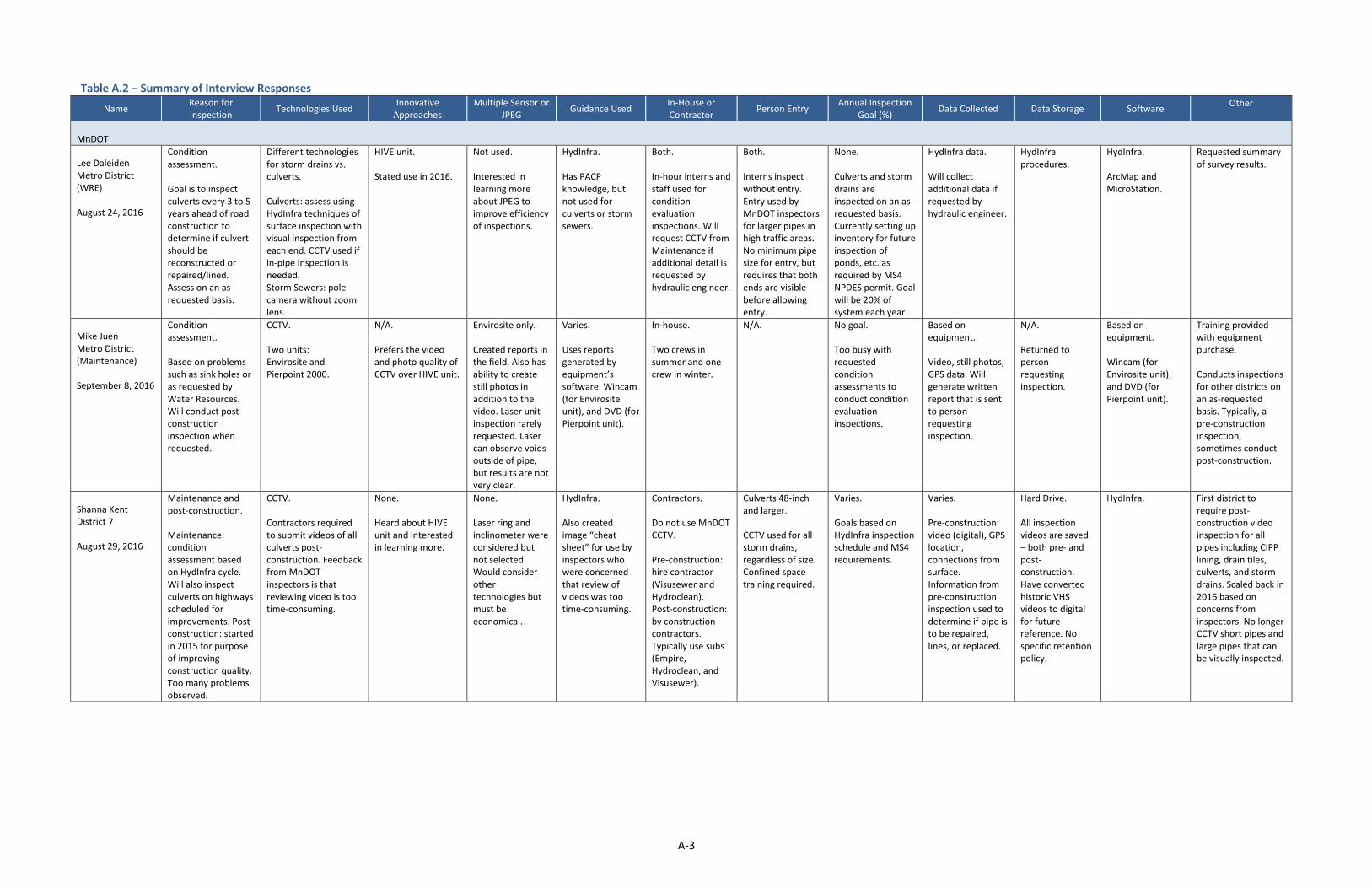
A-3
Table A.2 – Summary of Interview Responses
Name Reason for Inspection
Technologies Used Innovative
Approaches Multiple Sensor or
JPEG Guidance Used
In-House or Contractor
Person Entry Annual Inspection
Goal (%) Data Collected Data Storage Software
Other
MnDOT
Lee Daleiden Metro District (WRE)
August 24, 2016
Condition assessment.
Goal is to inspect culverts every 3 to 5 years ahead of road construction to determine if culvert should be reconstructed or repaired/lined. Assess on an as-requested basis.
Different technologies for storm drains vs. culverts.
Culverts: assess using HydInfra techniques of surface inspection with visual inspection from each end. CCTV used if in-pipe inspection is needed. Storm Sewers: pole camera without zoom lens.
HIVE unit.
Stated use in 2016.
Not used.
Interested in learning more about JPEG to improve efficiency of inspections.
HydInfra.
Has PACP knowledge, but not used for culverts or storm sewers.
Both.
In-hour interns and staff used for condition evaluation inspections. Will request CCTV from Maintenance if additional detail is requested by hydraulic engineer.
Both.
Interns inspect without entry. Entry used by MnDOT inspectors for larger pipes in high traffic areas. No minimum pipe size for entry, but requires that both ends are visible before allowing entry.
None.
Culverts and storm drains are inspected on an as-requested basis. Currently setting up inventory for future inspection of ponds, etc. as required by MS4 NPDES permit. Goal will be 20% of system each year.
HydInfra data.
Will collect additional data if requested by hydraulic engineer.
HydInfra procedures.
HydInfra.
ArcMap and MicroStation.
Requested summary of survey results.
Mike Juen Metro District (Maintenance)
September 8, 2016
Condition assessment.
Based on problems such as sink holes or as requested by Water Resources. Will conduct post-construction inspection when requested.
CCTV.
Two units: Envirosite and Pierpoint 2000.
N/A.
Prefers the video and photo quality of CCTV over HIVE unit.
Envirosite only.
Created reports in the field. Also has ability to create still photos in addition to the video. Laser unit inspection rarely requested. Laser can observe voids outside of pipe, but results are not very clear.
Varies.
Uses reports generated by equipment’s software. Wincam (for Envirosite unit), and DVD (for Pierpoint unit).
In-house.
Two crews in summer and one crew in winter.
N/A. No goal.
Too busy with requested condition assessments to conduct condition evaluation inspections.
Based on equipment.
Video, still photos, GPS data. Will generate written report that is sent to person requesting inspection.
N/A.
Returned to person requesting inspection.
Based on equipment.
Wincam (for Envirosite unit), and DVD (for Pierpoint unit).
Training provided with equipment purchase.
Conducts inspections for other districts on an as-requested basis. Typically, a pre-construction inspection, sometimes conduct post-construction.
Shanna Kent District 7
August 29, 2016
Maintenance and post-construction.
Maintenance: condition assessment based on HydInfra cycle. Will also inspect culverts on highways scheduled for improvements. Post-construction: started in 2015 for purpose of improving construction quality. Too many problems observed.
CCTV.
Contractors required to submit videos of all culverts post-construction. Feedback from MnDOT inspectors is that reviewing video is too time-consuming.
None.
Heard about HIVE unit and interested in learning more.
None.
Laser ring and inclinometer were considered but not selected. Would consider other technologies but must be economical.
HydInfra.
Also created image “cheat sheet” for use by inspectors who were concerned that review of videos was too time-consuming.
Contractors.
Do not use MnDOT CCTV.
Pre-construction: hire contractor (Visusewer and Hydroclean). Post-construction: by construction contractors. Typically use subs (Empire, Hydroclean, and Visusewer).
Culverts 48-inch and larger.
CCTV used for all storm drains, regardless of size. Confined space training required.
Varies.
Goals based on HydInfra inspection schedule and MS4 requirements.
Varies.
Pre-construction: video (digital), GPS location, connections from surface. Information from pre-construction inspection used to determine if pipe is to be repaired, lines, or replaced.
Hard Drive.
All inspection videos are saved – both pre- and post-construction.Have converted historic VHS videos to digital for future reference. Nospecific retention policy.
HydInfra. First district to require post-construction video inspection for all pipes including CIPP lining, drain tiles, culverts, and storm drains. Scaled back in 2016 based on concerns from inspectors. No longer CCTV short pipes and large pipes that can be visually inspected.

A-4
Name Reason for Inspection
Technologies Used Innovative
Approaches Multiple Sensor or
JPEG Guidance Used
In-House or Contractor
Person Entry Annual Inspection
Goal (%) Data Collected Data Storage Software
Other
Kris Langlie District 6 September 6, 2016
Pre-construction, asset management, and post-construction. Pre-construction is main focus. Also inspect poorest quality culverts, typically can inspect 80 percent of required HydInfra inspections. Post-construction on an as-needed basis. Considering post-construction requirements similar to District 7 approach.
Trimble Yuma 2. Collects GPS coordinates and elevation data. Elevation accuracy is +/- 1 meter. Requests Metro District when CCTV is needed. Developed HIVE unit for interior video.
HIVE. Camera mounted on remote control car with 4-wheel drive. Sony action camera with LED cap lights (typically used by hunters). Remote control operation of both car and camera. Use tether to measure length. Camera connects to tablet via Wifi. HIVE will drive through water and over debris. Camera will record under water, but visibility is limited if deeper than 4 inches. Biggest limitation is that HIVE unit can become stuck, especially on rusted pipes with missing inverts.
None. May consider for a situation where extent of voids is required.
HydInfra. Used to be consistent between all inspections.
In-house. Have used contractors in past, before development of HIVE unit. May consider for future in storm drains where HIVE communications do not work. Use summer interns.
Yes. Will send person into pipe. No minimum diameter but will not enter if pipe is less than 46 inches. May also conduct entry inspection and HIVE inspection of same pipe.
80 percent of HydInfra required inspections, 25 percent of MS4 outfalls. HIVE not used for HydInfra inspections. Too slow. Conducting MS4 inspection of outfalls. Starting to map ponds and other BMPs which eventually will be inspected.
HydInfra based data collection. HIVE – will stop at every joint, pivot to record full diameter of joint. Stop at all other visual problems. Make notes in the field as HIVE is progressing through pipe. HIVE unit is primarily used for pre-construction inspection to be able to determine repair method. Will look at hydraulic capacity, condition, etc. before determining whether to line or replace. Preferred approach is CIPP lining. Chemical injection used to fill voids when possible.
Server. HydInfra database is stored on server. Maintain separate hard copy and scanned inspection sheets in project files. No data retention policy – save everything.
HydInfra. HIVE was developed in 2015. Have made additional units for Metro District and now have money to make for all Districts. To-date, the unit has not needed major maintenance. Would like outfall inspection reminder similar to HydInfra inspection reminder each year.
Bonnie Peterson Metro District (HydInfra) August 23, 2016
N/A. HydInfra not used for asset management. Basic purpose is to inspect culverts.
N/A. Maintenance districts determine technique to inspect. Most common approach is to visually look into pipe from each end.
N/A. N/A. Interested in learning about best in-pipe techniques that give the best quality data at the best price.
HydInfra. Tier 1 inspection is baseline (pre-2010 inspections). Pipes with problems are referred to hydraulic engineers to determine if additional inspection is necessary.
Both. Most HydInfra inspections are by in-house staff. Specialty work, such as CCTV, may be contracted.
N/A. HydInfra goal. Inspect all culverts prior to 2010. After 2010 Districts are expected to regularly inspect on 1 to 6-year cycle based on initial inspection results. Each year, District should inspect 80 percent of required inspections. 117,000 pipes inspected to-date. Each District is inconsistent in ongoing inspection. Believes that data is outdated and needs corrections.
HydInfra data. Culverts, only. Does not apply to storm drains or manholes. Used as performance measure for visual defects.
Oracle database. Web-based reports (crystal report) can be generated as needed for project design reports. Also linked to GIS.
HydInfra. Considering linking to hydraulic modeling software. To be determined as part of asset management system development.
HydInfra coordinator since 1996. Provides support to staff. Costs are important.
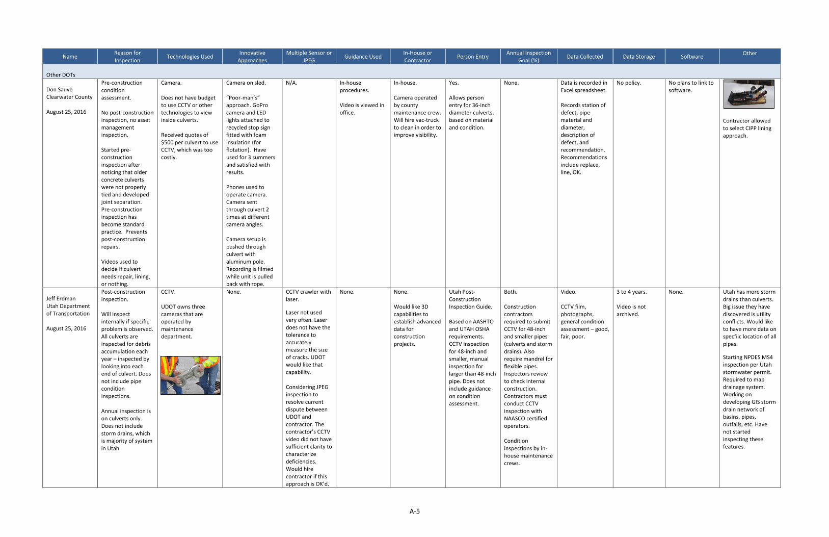
A-5
Name Reason for Inspection
Technologies Used Innovative
Approaches Multiple Sensor or
JPEG Guidance Used
In-House or Contractor
Person Entry Annual Inspection
Goal (%) Data Collected Data Storage Software
Other
Other DOTs
Don Sauve Clearwater County August 25, 2016
Pre-construction condition assessment. No post-construction inspection, no asset management inspection. Started pre-construction inspection after noticing that older concrete culverts were not properly tied and developed joint separation. Pre-construction inspection has become standard practice. Prevents post-construction repairs. Videos used to decide if culvert needs repair, lining, or nothing.
Camera. Does not have budget to use CCTV or other technologies to view inside culverts. Received quotes of $500 per culvert to use CCTV, which was too costly.
Camera on sled. “Poor-man’s” approach. GoPro camera and LED lights attached to recycled stop sign fitted with foam insulation (for flotation). Have used for 3 summers and satisfied with results. Phones used to operate camera. Camera sent through culvert 2 times at different camera angles. Camera setup is pushed through culvert with aluminum pole. Recording is filmed while unit is pulled back with rope.
N/A. In-house procedures. Video is viewed in office.
In-house. Camera operated by county maintenance crew. Will hire vac-truck to clean in order to improve visibility.
Yes. Allows person entry for 36-inch diameter culverts, based on material and condition.
None. Data is recorded in Excel spreadsheet. Records station of defect, pipe material and diameter, description of defect, and recommendation. Recommendations include replace, line, OK.
No policy. No plans to link to software.
Contractor allowed to select CIPP lining approach.
Jeff Erdman Utah Department of Transportation August 25, 2016
Post-construction inspection. Will inspect internally if specific problem is observed. All culverts are inspected for debris accumulation each year – inspected by looking into each end of culvert. Does not include pipe condition inspections. Annual inspection is on culverts only. Does not include storm drains, which is majority of system in Utah.
CCTV. UDOT owns three cameras that are operated by maintenance department.
None. CCTV crawler with laser.
Laser not used very often. Laser does not have the tolerance to accurately measure the size of cracks. UDOT would like that capability. Considering JPEG inspection to resolve current dispute between UDOT and contractor. The contractor’s CCTV video did not have sufficient clarity to characterize deficiencies. Would hire contractor if this approach is OK’d.
None. None. Would like 3D capabilities to establish advanced data for construction projects.
Utah Post-Construction Inspection Guide. Based on AASHTO and UTAH OSHA requirements. CCTV inspection for 48-inch and smaller, manual inspection for larger than 48-inch pipe. Does not include guidance on condition assessment.
Both. Construction contractors required to submit CCTV for 48-inch and smaller pipes (culverts and storm drains). Also require mandrel for flexible pipes. Inspectors review to check internal construction. Contractors must conduct CCTV inspection with NAASCO certified operators. Condition inspections by in-house maintenance crews.
Video. CCTV film, photographs, general condition assessment – good, fair, poor.
3 to 4 years. Video is not archived.
None. Utah has more storm drains than culverts. Big issue they have discovered is utility conflicts. Would like to have more data on specfiic location of all pipes.
Starting NPDES MS4 inspection per Utah stormwater permit. Required to map drainage system. Working on developing GIS storm drain network of basins, pipes, outfalls, etc. Have not started inspecting these features.

A-6
Name Reason for Inspection
Technologies Used Innovative
Approaches Multiple Sensor or
JPEG Guidance Used
In-House or Contractor
Person Entry Annual Inspection
Goal (%) Data Collected Data Storage Software
Other
Mike Hogan Ted Lapierre Mike Maysayda Connecticut Department of Transportation August 30, 2016
Pre-construction condition assessment, post-construction. All storm drains inspected in advance of construction and results assessed by drainage engineer. Bridges (6-foot and larger) are inspected on 2-year cycle. Post-construction visual inspection is for all culverts. Televised is being considered. Developing program for MS4 inspections of outfalls, CBs, culverts, etc.
Varies. Bridges – visual. Maintenance uses probe camera which will view 80 feet of culvert length. Sonar imaging used for underwater piers. CCTV used for internal inspections.
3D scans. Pre-construction – 3D laser scan using Leica Nova MS50.
Used for emergency inspection of failing culvert on I-90. Too dangerous to access for internal inspection. Used Leica scan to create cross-section of deformations. Was able to map deformations to design liner. Will use in future for similar situations.
Not used. Varies. Bridges – use in-house inspection manual. Also reference FHWA manuals. Maintenance – no guidance developed. Visual notes of condition. Use best judgment when looking for deterioration and settlement. Contractors required to use CT bridge inspection standards.
Both. In-house inspectors used for culverts. Will hire contractor if culvert is underwater, has heavy siltation, or poor air quality from decomposing organics.
Case-by-case. 4-foot clearance required for person entry. Must be able to stand or hunch within pipe, crawling not allowed. Confined space training required for everyone entering pipe. Develop procedures for manhole entry including air quality testing, communications, etc. DOT issues permits for inspection.
Varies. Setting up annual inspection goals to meet MS4 inspection requirements. Bridge inspection required on 2- to 4-year cycle, depending on condition.
Varies. Bridges – visual inspection to collect data to assign condition rating. MS4 data collection being developed. Developing system to link data tales to GIS.
ProjectWise. Store all plans, reports, inspection reports on ProjectWise in single location. No long-term retention policy.
Under development. Working on asset management system that will be GIS-based.
Hydrolink Issue
12.pdf
Therese Kline
Michigan
Department of
Transportation
September 1, 2017
Condition
assessment, post-
construction.
Condition
assessments are
done on an as-
needed basis,
typically problem
based. Post-
construction
mandrel testing
required for plastic
pipe only.
Setting up asset
management system
that may initiate
more extensive
culvert inspection
program.
Laser ring.
Laser ring was used
specifically to study a
series of culverts that
were initially assessed
30 years ago. Goal was
to make sure that
pipes were still on
track of 50-year life
cycle. Considered laser
ring, rotating head, fish
lens, and CCTV. Chose
laser ring because the
results were the most
consistent. Slower
speed of equipment
discovered more
anomalies. Higher
speed units passed by
problem areas too
quickly.
GoPro.
Tried by others in
Michigan.
CCTV with on-
board
inclinometer and
digital video.
Preferred laser
ring because the
slower speed of
movement
through the
culvert discovered
more anomalies.
Not standardized.
Bridge inspections
have standardized
approaches to
inspections, but
culvert inspections
are not
standardized.
Always start on
downstream side.
Use FHWA 1986
guidance for
special studies,
such as laser ring
assessment of
older culverts.
In-house.
Contractors hired
for special
research only.
Depends.
Will enter only if
culvert is secure,
not collapsed.
Prefer technology
inspection over
person entry. Will
use confined space
trained personnel
when entry is
required.
None. Varies.
Cracks, holes,
slope, shoulder
condition, road
condition, other
utility issues,
upstream and
downstream end
sections.
As-builts checked,
when available.
ProjectWise.
Eventually will
add culvert
inspection data
to GIS based
asset
management
system. Hope to
include a simple
condition
assessment field
in the database.
Currently store
graphics and data
on ProjectWise.
None.
Working towards
GIS based asset
management
system.
Requested copy of
final report.
Laser ring study was
one-time special
study of culverts that
were video recorded
30 years ago.
Conducted a random
sample of
installations of metal,
concrete, and plastic
pipe.
https://www.michiga
n.gov/documents/m
dot/RC-
1569_451946_7.pdf
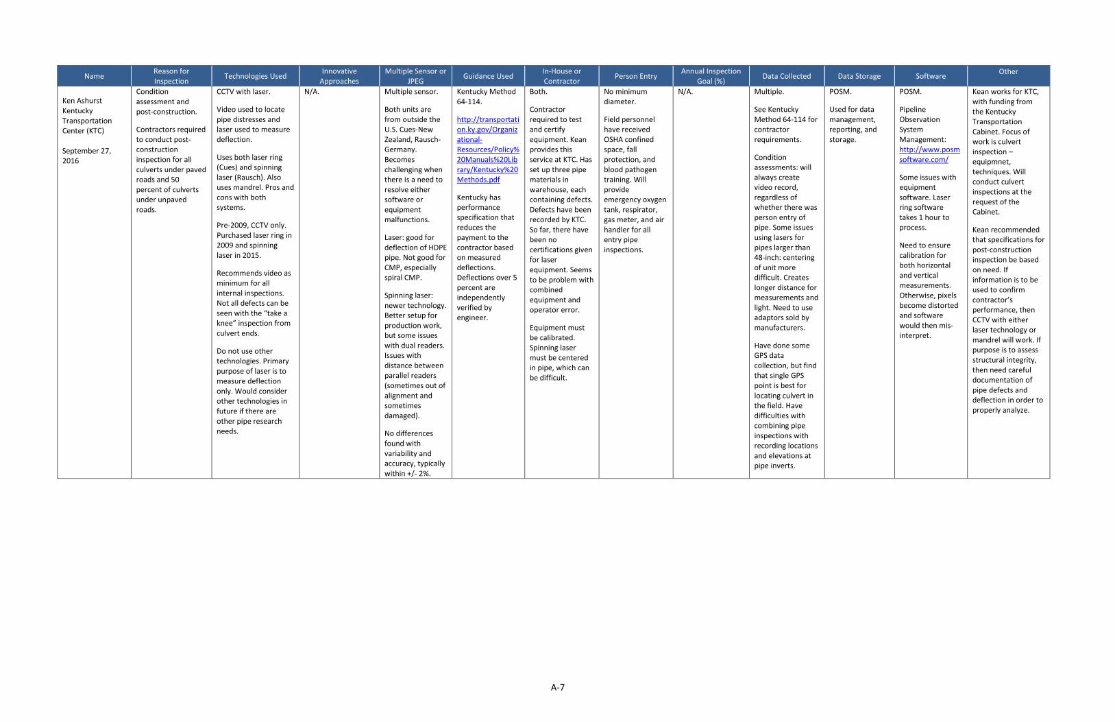
A-7
Name Reason for Inspection
Technologies Used Innovative
Approaches Multiple Sensor or
JPEG Guidance Used
In-House or Contractor
Person Entry Annual Inspection
Goal (%) Data Collected Data Storage Software
Other
Ken Ashurst Kentucky Transportation Center (KTC) September 27, 2016
Condition assessment and post-construction.
Contractors required to conduct post-construction inspection for all culverts under paved roads and 50 percent of culverts under unpaved roads.
CCTV with laser.
Video used to locate pipe distresses and laser used to measure deflection.
Uses both laser ring (Cues) and spinning laser (Rausch). Also uses mandrel. Pros and cons with both systems.
Pre-2009, CCTV only. Purchased laser ring in 2009 and spinning laser in 2015.
Recommends video as minimum for all internal inspections. Not all defects can be seen with the “take a knee” inspection from culvert ends.
Do not use other technologies. Primary purpose of laser is to measure deflection only. Would consider other technologies in future if there are other pipe research needs.
N/A. Multiple sensor.
Both units are from outside the U.S. Cues-New Zealand, Rausch-Germany. Becomes challenging when there is a need to resolve either software or equipment malfunctions.
Laser: good for deflection of HDPE pipe. Not good for CMP, especially spiral CMP.
Spinning laser: newer technology. Better setup for production work, but some issues with dual readers. Issues with distance between parallel readers (sometimes out of alignment and sometimes damaged).
No differences found with variability and accuracy, typically within +/- 2%.
Kentucky Method 64-114.
http://transportation.ky.gov/Organizational-Resources/Policy%20Manuals%20Library/Kentucky%20Methods.pdf
Kentucky has performance specification that reduces the payment to the contractor based on measured deflections. Deflections over 5 percent are independently verified by engineer.
Both.
Contractor required to test and certify equipment. Kean provides this service at KTC. Has set up three pipe materials in warehouse, each containing defects. Defects have been recorded by KTC. So far, there have been no certifications given for laser equipment. Seems to be problem with combined equipment and operator error.
Equipment must be calibrated. Spinning laser must be centered in pipe, which can be difficult.
No minimum diameter.
Field personnel have received OSHA confined space, fall protection, and blood pathogen training. Will provide emergency oxygen tank, respirator, gas meter, and air handler for all entry pipe inspections.
N/A. Multiple.
See Kentucky Method 64-114 for contractor requirements.
Condition assessments: will always create video record, regardless of whether there was person entry of pipe. Some issues using lasers for pipes larger than 48-inch: centering of unit more difficult. Creates longer distance for measurements and light. Need to use adaptors sold by manufacturers.
Have done some GPS data collection, but find that single GPS point is best for locating culvert in the field. Have difficulties with combining pipe inspections with recording locations and elevations at pipe inverts.
POSM.
Used for data management, reporting, and storage.
POSM.
Pipeline Observation System Management: http://www.posmsoftware.com/
Some issues with equipment software. Laser ring software takes 1 hour to process.
Need to ensure calibration for both horizontal and vertical measurements. Otherwise, pixels become distorted and software would then mis-interpret.
Kean works for KTC, with funding from the Kentucky Transportation Cabinet. Focus of work is culvert inspection – equipmnet, techniques. Will conduct culvert inspections at the request of the Cabinet.
Kean recommended that specifications for post-construction inspection be based on need. If information is to be used to confirm contractor’s performance, then CCTV with either laser technology or mandrel will work. If purpose is to assess structural integrity, then need careful documentation of pipe defects and deflection in order to properly analyze.
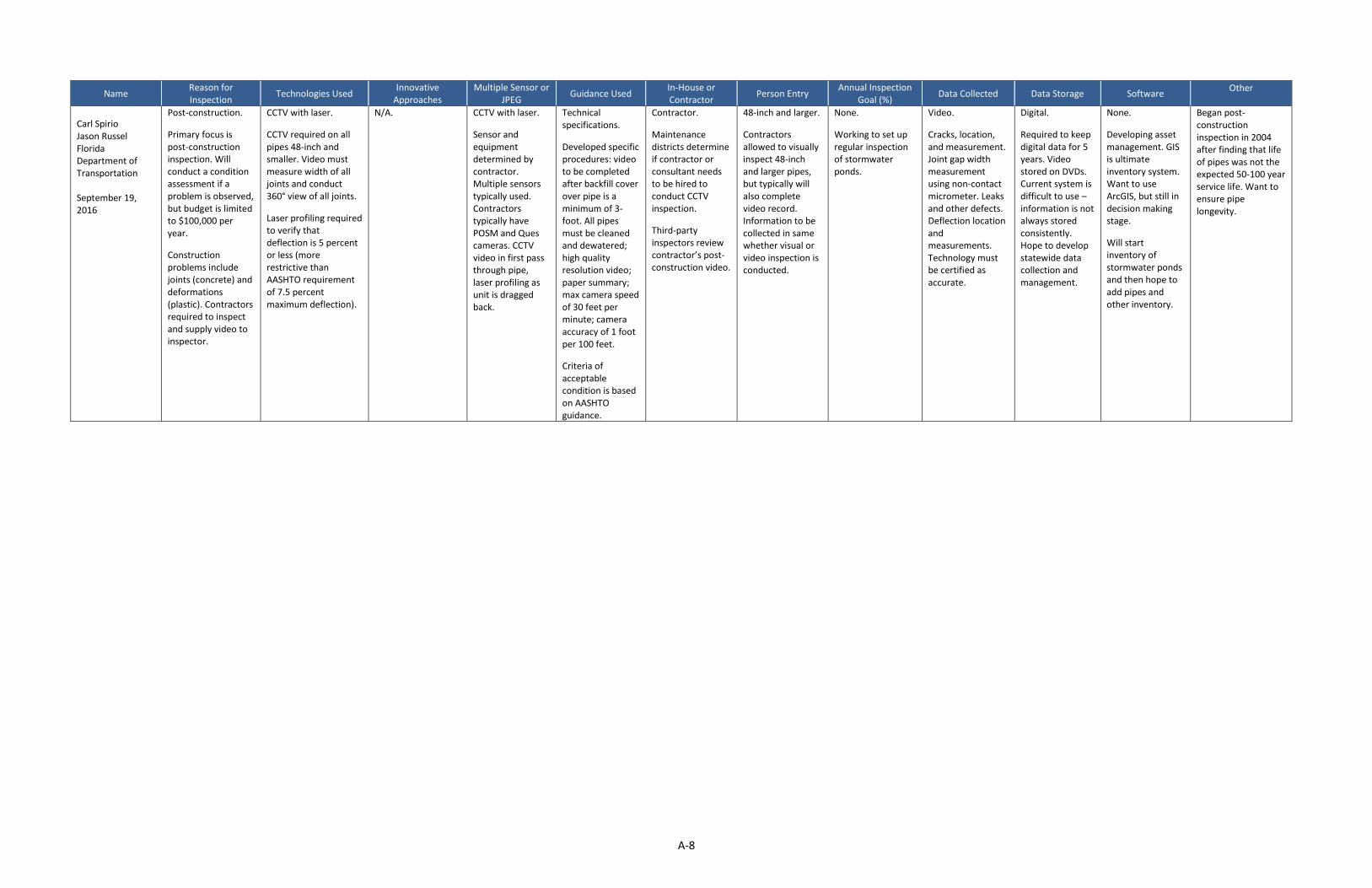
A-8
Name Reason for Inspection
Technologies Used Innovative
Approaches Multiple Sensor or
JPEG Guidance Used
In-House or Contractor
Person Entry Annual Inspection
Goal (%) Data Collected Data Storage Software
Other
Carl Spirio Jason Russel Florida Department of Transportation September 19, 2016
Post-construction.
Primary focus is post-construction inspection. Will conduct a condition assessment if a problem is observed, but budget is limited to $100,000 per year.
Construction problems include joints (concrete) and deformations (plastic). Contractors required to inspect and supply video to inspector.
CCTV with laser.
CCTV required on all pipes 48-inch and smaller. Video must measure width of all joints and conduct 360° view of all joints.
Laser profiling required to verify that deflection is 5 percent or less (more restrictive than AASHTO requirement of 7.5 percent maximum deflection).
N/A. CCTV with laser.
Sensor and equipment determined by contractor. Multiple sensors typically used. Contractors typically have POSM and Ques cameras. CCTV video in first pass through pipe, laser profiling as unit is dragged back.
Technical specifications.
Developed specific procedures: video to be completed after backfill cover over pipe is a minimum of 3-foot. All pipes must be cleaned and dewatered; high quality resolution video; paper summary; max camera speed of 30 feet per minute; camera accuracy of 1 foot per 100 feet.
Criteria of acceptable condition is based on AASHTO guidance.
Contractor.
Maintenance districts determine if contractor or consultant needs to be hired to conduct CCTV inspection.
Third-party inspectors review contractor’s post-construction video.
48-inch and larger.
Contractors allowed to visually inspect 48-inch and larger pipes, but typically will also complete video record. Information to be collected in same whether visual or video inspection is conducted.
None.
Working to set up regular inspection of stormwater ponds.
Video.
Cracks, location, and measurement. Joint gap width measurement using non-contact micrometer. Leaks and other defects. Deflection location and measurements. Technology must be certified as accurate.
Digital.
Required to keep digital data for 5 years. Video stored on DVDs. Current system is difficult to use – information is not always stored consistently. Hope to develop statewide data collection and management.
None.
Developing asset management. GIS is ultimate inventory system. Want to use ArcGIS, but still in decision making stage.
Will start inventory of stormwater ponds and then hope to add pipes and other inventory.
Began post-construction inspection in 2004 after finding that life of pipes was not the expected 50-100 year service life. Want to ensure pipe longevity.

APPENDIX B SUMMARY OF RELATED LITERATURE

B-1
Culvert Inventory and Inspection Manual New York State Department of Transportation, May 2006
Summary
This document presents recommended best practices for conducting a culvert inventory and inspection, as published by the New York State Department of Transportation.
Conclusions
If the inspection is a re-check of existing data, best practice is to print out prior inspection information. It is easier to verify the accuracy of existing data than conducting a new inspection.
Inspection frequency should be based on condition rating. New York State DOT has a 9-level rating. Ratings of 1 to 7 relate to observed condition. A rating of 1 is poor condition and a rating of 7 is good condition. Ratings 8 and 9 relate to N/A data.
o If the culvert has a condition score of 1 or 2, annual inspections are recommended.
o If the culvert has a condition score of 3 or 4, inspections every other year are recommended.
o If a culvert has a condition score of 5 through 7, inspections every four years are recommended.
Recommended inspection procedures are to: 1) review plans and maps; 2) print out plans and maps; 3) review the most current inspection data; 4) print the most current inspections; 5) inspect the culvert, not if the invert is concealed by water and note if the culvert is in imminent risk of failure; 6) if failure is imminent, report immediately; and, 7) submit inspection results to the computerized condition management system.
Note settlement above the culvert. Above-grade settlement can be indicative of culvert damage. Note the approximate location of above-grade settlement in the culvert.
Practical Factors and Considerations Related to Culvert Inspection Contech, July 2010
Summary
This document presents a brief overview of important factors to consider when inspecting a culvert. Important factors include shape, size, material, and use of the culvert.
Safety
Safety during an inspection is of primary concern. Cost-effective tools exist to avoid person entry. If person entry is required, inspect during low flows, if the culvert is stable, if there is appropriate headroom, and with an inspection partner.
Conclusions
Plastic Culvert

B-2
Plastic culvert relies on surrounding soil to support the culvert. If the surrounding fill is not properly constructed, deformations will occur.
Applicable damage for plastic culvert includes deformation, deflections, stress cracking, and wall buckling.
Metal Culvert
Applicable damage for a CMP culvert includes deformation, deflections, cracking, delaminations, coating issues, and rust.
Concrete Culvert
Applicable damage for concrete culvert includes settlement, joint separation, cracks, and fractures.
Stone Culvert
Applicable damage includes deterioration of stone, spalling, and deformation.
A Research Plan and Report on Factors Affecting Culvert Service Life in Minnesota (Report 2012-27) Minnesota Department of Transportation, September 2012
Summary
Existing studies, design practice, manufacturer feedback, and available data were reviewed to identify guidelines for defining expected service life of culverts. In addition, future study needs were identified.
Conclusions
Highway surface is repaired to extend service life. The road core and culverts are not repaired as often.
The desired service life for culverts is 100 years for centerline and mainline highway culverts, and 50 to 75 years for entrance culverts.
The most common damage observed was joint separation. This study recommends gasketed joints to reduce the chance of joint separation.
The worst damaged culverts (score 3 or 4) correlate to road damage.
The most common damage for 24-inch to 36-inch culverts is joint damage.
Construction inspection is most often conducted by MnDOT inspectors. This study recommends that constructed culverts are inspected before commissioning.
Metal Culvert
If metal culverts are to be used, 16 gauge corrugated aluminized steel is recommended. Its service life is three times to eight times longer than galvanized.

B-3
Steel culvert is the second most common culvert used in Minnesota. The average steel culvert size is 22 inches.
If metal culvert is buried deeper (i.e., soil depth increases), there is higher occurrence of cracks and less occurrence of deformations.
Salt is a concern for metal culverts. If the chloride content in soils are low and pH is between 5 and 9, service life will be optimized.
Polymer coatings on metal culverts should be observed. If the coatings are scratched, the culvert material may corrode.
Plastic Culvert
PVC becomes brittle if temperature is less than 37° F. PVC shouldn’t be installed in cold weather.
HDPE is not as susceptible to low temperature damage. This culvert is more resistant to damage from freeze/thaw. HDPE does have an expected service life of more than 100 years.
According to AASHTO, installation method is the most important factor for long-term life of a
plastic culvert. Creep will be observed if there is an asymmetrical load.
HDPE creeps if temperatures are greater than 140° F.
PVC is brittle if temperatures are less than 37° F.
Most industry estimates of plastic culvert service life do not consider freeze/thaw. Several
organizations (e.g., Ontario Ministry of Transportation, US Corps of Engineers, Federal Highway
Administration) suggest HDPE has a service life closer to 50 year.
Most deformation occurs early in a plastic culvert’s life. Therefore, it is recommended that
culverts are inspected before a road is finished. It is recommended that MnDOT adopts a cost
reduction or warranty approach for deformed HDPE that cannot be repaired.
It is estimated that 85 percent of deflecting occurs within the first 7 days after construction. If
mandrel inspection is conducted after 1 week, it should observe most of the deformation.
Actual diameter of a plastic pipe can be approximately 2 percent to 3 percent different from the
nominal size. The actual diameter of the pipe should be confirmed with the pipe manufacturer.
Pipe manufacturers have indicated they would loan a mandrel that is calibrated to actual pipe size.
Concrete Culvert
Concrete culvert is the most common material used in Minnesota; 76 percent of the state’s
culverts are concrete.
The average concrete culvert size is 24 inches.
If a concrete culvert is buried deeper (i.e., soil depth increases), there is a higher occurrence of
joint separation.

B-4
Salt is a concern for concrete culvert. If the chloride content in soils are low and pH is between 5 and 9, service life will be optimized.
Culvert Repair Best Practices, Specifications, and Special Provisions – Best Practice Guidelines Minnesota Department of Transportation, January 2014
Summary
This document presents best practices for rehabilitating culverts.
Conclusions
Culverts with a HydInfra score of 3 or 4 need to receive repair, replacement, or rehabilitation.
Plastic Pipe
Plastic pipe can deflect up to 5 percent to 7 percent and still be stable and serviceable into the future.
Hydraulics Inspection Vehicle Explorer (HIVE) Fact Sheet Minnesota Department of Transportation
Summary
This fact sheet summarizes key parameters of the MnDOT-built HIVE unit. The HIVE unit is used to inspect and videotape culverts.
Conclusions
The HIVE unit is a 4-wheel drive, remote-controlled vehicle. The vehicle has a remotely pivotable
camera with LED lighting. The camera sends a wireless signal to a handheld tablet.
The HIVE unit costs about $1,200 for the car and camera. A tablet costs about $300.
The camera is described as being designed to provide visual inspection of concrete joints and metal surfaces for culverts that cannot be physically entered (<3 feet).
Implementation of Specification 430-4.8 (Pipe Inspection) on Construction Projects let Prior to January 1, 2013 Florida Department of Transportation, July 2013, DCE Memo No. 17-13
Summary
This memorandum contains several specification clauses for culvert inspection.
Laser Profile Calibration Criteria Florida Department of Transportation
Summary
This document provides a brief summary of the procedure to calibrate a laser profiling unit.

B-5
Conclusions
Equipment calibration should follow ASTM E691 and ASTM E177.
Note that the specific calibration procedure is equipment-specific and should follow manufacturer recommendations.
Pipe Inspection and Repair – 2014 Construction Academy Presentation Florida Department of Transportation, August 2014
Conclusions
Pipe under roadways should be inspected when backfill is 3 feet above the pipe crown or upon compaction of stabilized subgrade.
Pipes should be dewatered and clean before inspections.
Laser Profiling
There are two types of laser profiler: 1) a rotating head profiler; and, 2) a continuous laser ring.
CCTV should be used to interpret laser scan results.
There are some limitations with inspection speed. Do not inspect too fast.
Laser scan is helpful in obtaining an ovality report, deflection report, and inclination reports.
Construction Acceptance Criteria
Leak test results should be: Cross Drains are soil tight, Storm Drains are soil tight, Gutter Drains are water tight, and Side Drains are soil tight.
Soil tight should hold 2 psi when tested. Water tight should hold 5 psi when tested.
Joint gap tolerances were presented for concrete pipe with rubber gaskets. If the pipe is 12-inch to 18-inch and has a gap > 5/8-inch, it is unacceptable. If the pipe is 24-inch to 66-inch and has a gap > 7/8-inch, it is unacceptable. If the pipe is 72-inch or larger and the gap is > 1-inch, it is unacceptable.
Deflection tolerances were specified. If deflection is 5 percent or greater than the certified mean diameter, the test fails. This criterion is based upon AASHTO standards for deflection.
Crack tolerances were specified and based on ASTM C76 and AASHTO Section 27.4.1. If cracks in a reinforced concrete pipe are greater than 0.01-inch, the culvert fails the test.
Staining tolerances were discussed. If staining is observed and the culvert has a crack near the stain greater than 0.01-inch, there is an issue. If active infiltration is observed, repair is needed.
MnDOT Newsline – District 6 Workers Collaborate to Build Hydraulic Inspection Explorer, Start Production for Others Minnesota Department of Transportation, April 2016

B-6
Summary
This news article provided information on the development and deployment of the MnDOT HIVE inspection unit.
Conclusions
The HIVE camera was built out of the Rochester District.
One HIVE unit was built for the metro area.
Illustrated Guide to the HydInfra Manual 2016 Minnesota Department of Transportation, 2016
Conclusions
HydInfra is a tool MnDOT uses to capture pertinent information about culverts, estimate repair needs, and prioritize repairs. Recommended repairs are based upon a decision tree tool. Prioritization is based upon a 5-point scoring system. A score of 0 indicates the culvert is not visible or able to be rated. Scores of 1 through 4 indicate condition, with a score of 4 being very bad and 1 being good.
MnDOT uses HydInfra to rate culverts that are less than 10 feet in diameter.
It is recommended that the culvert is cleaned if it is more than 30 percent full of sediment.
Culverts with a score of 4 are in the worst condition. Conditions that generate a score of 4 include: soil loss, loss of road support, concrete joints separated more than 3 inches, holes that are more than 1 inch in diameter, many small holes < 1 inch in diameter, and plastic pipe deformed more than 10 percent of the original internal diameter.
Laser Profiler Demonstration Comparative Analysis – PowerPoint Presentation Michigan Department of Transportation
Summary
The Michigan Department of Transportation laser scan inspections provided by Cues, Raugh, RST, and BAK inspection units. This comparison was conducted to identify the quality of these laser scan units. Note this study was a comparison of the camera technologies and not a comparison of various inspection methods. Technical parameters from each unit were identified.
Conclusions
Each camera was able to provide an evaluation of pipe ovality.
Camera costs ranged from $118,705 to $253,900 per camera unit. All costs included data
processing software costs.
All cameras had deficiencies. These deficiencies appear to be inherent to the technology. Data was difficult to collect near manholes, corrugated pipes had a shadow effect that impacted data review and post-processing, and calibration is required in the field which may introduce human error.

B-7
HDPE Pipe Failure at Texas Fish Hatchery Offers Costly Lesson American Concrete Pipe Association
Summary
Approximately 11,000 feet of HDPE pipe was inspected and identified to have questionable structural integrity at the John D. Parker East Texas Fish Hatchery near Jasper.
Conclusions
HDPE is a flexible material and not an independent structure like reinforced concrete pipe. Most of its successful installation is driven by the soil envelope surrounding the material. It is important for the design to account for a range of pipe-soil variables when dealing with HDPE.
Evaluation of HDPE Pipelines Structural Performance on Texas DOT and Municipal Projects Abolmaali and Mothari, December 2007
Summary
This study evaluated the performance of 22 existing HDPE pipes in Texas.
Conclusions
Approximately 38 percent of the pipes were deformed more than 5 percent.
Deformation for all pipes ranged from 1.7 percent to 22.5 percent.
Average deformation was 6.8 percent.
International Infrastructure Management Manual International Public Works Engineering Australia, 2015
Summary
This manual provides standards for conducting an asset management program for a utility that owns public assets. Sections covering collecting asset information, monitoring asset performance/condition, and managing risk were reviewed. Broad asset management principles are presented in this resource.
Conclusions
Organizations need to capture and manage data while balancing this cost against the expected
benefits.
If an asset is newly constructed, the International Infrastructure Management Manual recommends making every attempt to collect data at the time of construction commissioning. It has been observed that the cost of collecting this data at construction is 25 percent the cost of collecting similar data after 10 years.
Condition Assessment Strategies and Protocols Water Environment Research Federation, 2007
Summary

B-8
This guidance document includes Appendix F, which is a state-of-the-art industry summary of pipe inspection technologies. The document is developed for the water/wastewater industry; however, many of the common culvert inspection technologies are included in the summary. Technologies that are discussed in detail include CCTV inspection, laser scanning, and physical measurement.
Culvert Repair Practices Manual Federal Highway Administration, 1995
Summary
This manual presents an overview of the types of failures one can expect for different pipe materials.
Culvert Inspection Manual Federal Highway Administration, 1986
Summary
This manual was reviewed to understand the long-standing best practices for culvert inspection. This manual does not consider enhanced inspection technologies, but is a good resource to understand existing practices.
Pipe Assessment and Certification Reference Manual National Association of Sanitary Sewer Companies (NASSCO), 2015
Summary
The Pipe Assessment and Certification Program reference manual proposes best practices when one conducts a camera-based inspection. This manual also recommends inspection coding and risk assessment methods. MnDOT uses the HydInfra method, so coding and risk assessment were not reviewed in depth.
Conclusions
Provide an unobstructed view of the pipe surface during inspection. To this end, conduct pipe cleaning prior to inspection.
Inspection cameras should continue through the pipe at a steady pace not exceeding 30 feet per minute. The camera should come to a complete stop when a defect is observed.
The camera should be stopped when the pan and tilt function is used.
The camera’s onboard footage counter should be set such that a footage of 0 is at the entrance of the culvert.
The camera should be centered in the culvert to avoid image distortion. Image distortion is a major issue if one is attempting to assess conduit ovality.
Lighting should be considered. Low lighting will prevent an inspector from viewing the culvert
crown. Over lighting will cause lens flaring and wash out the color of the conduit wall.
The camera should be calibrated for proper color. Distorted colors can result in an inaccurate
evaluation of condition.

B-9
Laser profiling is more useful in: measuring pipe deformation, ovality, changes in cross section,
and estimates of wall deterioration.
Conduits should be cleaned to restore 95 percent of the pipe cross section prior to inspection.
The camera lens should be cleaned prior to inspection to remove grease from the lens.
Culvert and Storm Drain System Inspection Manual Transportation Research Board of the National Academies, 2016
Summary
This document presents an inspection manual for assessing condition of culverts and storm drain systems. A rating system is presented for grading the condition of culverts.
Conclusions
Inspection frequency is based on a culvert’s condition rating. Culverts in poor condition will be inspected more frequently.
Remote inspection (e.g., CCTV, laser scan) is recommended when the storm drains have limited access or are too small for person entry.
Four types of inspection were identified: Initial / Inventory, Routine, Special and Damage Inspections.
Example Specification – Camera/Video Inspection of Pipe with Alternate Methods of Deflection Measurement
Kentucky Department of Transportation, June 2012
Summary
This specification provides example specification language for CCTV inspection, laser scanning, mandrel testing, and physical measurement.
Example Specification – Section 701 Culvert Pipe, Entrance Pipe, Storm Sewer Pipe and Equivalents Kentucky Department of Transportation, 2012
Summary
This specification provides example language for CCTV inspection after construction of culverts and storm sewers.
Example Specification – Special Provision for Laser Inspection of Sewer and Culvert Pipe Minnesota Department of Transportation, July 2010
Summary
This specification provides example language for laser inspection.
Minnesota Department of Transportation – District 7

B-10
Summary
This specification provides example language for CCTV inspection of stormwater features (e.g., pipes, culverts). This specification is developed to be used regardless of the use of the inspection. That is, it can be used for post-construction inspections or condition inspections.
Example Specification – Culvert and Pipe Lining Federal Highway Administration
Summary
This specification provides example language for rehabilitating culverts with a pipe liner system.
Conclusions
All rehabilitation must have a CCTV or person entry inspection prior to rehabilitation.
CCTV video is required prior to acceptance.
Example Specification – Conduit Inspection Equipment Ohio Department of Transportation, December 2012
Summary
This specification provides example language for specifying CCTV inspection, laser profiling, and mandrel equipment. The specification is focused on technical requirements of the technology.
Survey of MnDOT District Use of Video Cameras Minnesota Department of Transportation April 2015
Summary
This summary table documents the results of six questions asked to seven MnDOT staff members regarding their use of video cameras for culvert inspection. Questions include:
Does your District have remote control video cameras for inspecting pipe?
What type of pipe do you inspect with it?
Does your District contact for video inspection? Who have you used?
What is the primary purpose that you do video inspection?
Have you ever used laser profiler (laser ring) or a video camera (mosaic jpg) that produces an image where you can accurately measure defects?
Are you interested in participating on a research technical advisory panel (TAP) on enhanced pipe inspections?
Example Specification – Drainage Pipe Utah Department of Transportation

B-11
Summary
This specification provides example language for specifying CCTV inspection after drainage pipes are constructed. The specification is focused on CCTV inspection and not laser ring inspection.
Example Specification – Drainage Pipe Arizona Department of Transportation, July 2005
Summary
This specification provides example language for specifying laser ring and CCTV inspection of newly constructed drainage pipe. This specification also provides language for requiring a mandrel inspection. The specification discusses equipment calibration.

APPENDIX C REVIEW OF SAMPLE INSPECTION VIDEO

C-1
MnDOT staff provided CDM Smith with 12 culvert inspection videos recorded between 2011 and 2016. CDM Smith reviewed all digital videos, which included 10 videos from the Metro District and two videos from District 7. Figure C.1 shows the locations of culverts that were reviewed.
The intent of this review process was to see examples of ‘good’ and ‘poor’ quality videos. This memorandum presents results of both a limited condition evaluation and a detailed quality evaluation of each inspection.
Each video was evaluated based on nine components of quality. These components of quality are based upon research and best practice recommendations published by the National Association of Sanitary Sewer Companies (NASSCO). NASSCO works to constantly review the state of the digital video inspection industry and identify quality standards. Components of quality that were reviewed include:
Video Quality – NASSCO’s current specification calls for inspection video that is a minimum of 650 x 480 pixels. This resolution is roughly equivalent to a standard definition DVD. While high-quality video resolution is not essential to a pipe inspection, contractor ideally should provide digital video that is of better quality than historic VHS-tapes.
Color Quality – Maintaining true color is important when inspecting culvert joints for discoloration and mineral deposits. If color is poor (i.e., too saturated, poor contrast), the inspector should adjust settings on the camera.
Lens Condition – The camera lens should remain clean throughout the entire inspection. If debris, grease or water obscures the lens, the inspector should clean the lens and re-inspect.
Lighting Condition – The camera unit should include lighting that is appropriate for the culvert size. Lighting should fully illuminate the entire culvert, but not over illuminate. Poor lighting will prevent the inspector from viewing the culvert’s crown condition. Over-lighting will wash out small damage on the culvert walls.
Centered View – The camera should be placed in the proper horizontal and vertical position to prevent image distortion. If the camera is not centered down the culvert, the image will be distorted and the inspector cannot assess whether the culvert is out-of-round.
Footage Counter Accuracy – The inspection unit should have a digital footage counter. This footage counter should start at 0 ft at the start of the inspection. If the counter is not set at 0 ft, one cannot correlate damage in the culvert to above grade issues.
Inspection Speed – NASSCO recommends that inspections are not conducted at a speed faster than 30 fpm. Faster speeds may miss recording damage.
Documentation of Damage – The inspector should stop the camera at damage and use the pan-and-tilt function to fully record the issue.
Condition Impacts to Quality – Often, culverts will not be cleaned prior to inspection. Ideally, culvert condition should be adequate to allow the camera a full and uninterrupted view of condition.

C-2

C-3
Pipe ID 658015 Location: I-35E and Mendota Heights Road (Metro) Pipe Information: Elliptical (27-inch by 19-inch) Corrugated Metal Pipe Inspection Conducted: June 3, 2011 Inspector: Visu-Sewer
Summary of Asset Condition
Culvert 658015 is corroded along the invert, along the entire 62.5-foot length of survey. Two joints have separated. A summary of damage observed during the inspection is provided in Table C.1.
Table C.1 – Summary of Damage
Video Time Footage (ft) Defect
1:31 11.4 Protruding root
1:39 17.8 Silty sand in the invert
1:48 23.6 Separated joint
2:01 0 – 62.5 Corrosion along invert
3:42 62.5 Debris along invert
Inspection Data Quality
In general, the inspection quality for culvert 658015 is good. Corrugated culvert material does impact video quality due to the camera jumping as it travels across the corrugation. Visu-Sewer does a good job at stopping at damage. Stopping at damage is essential for corrugated culverts to allow for clear documentation. Table C.2 summarizes the review of data quality.
Table C.2 – Summary of Inspection Data Quality
Quality Parameter Measurement Notes
Video Quality Color, Non-HD Video quality is acceptable for application.
Color Quality Saturation OK
Lens Condition Clean Throughout
Lighting Condition Crown Underlit Camera focuses on the corroded invert. Lighting is directional so condition is not focused on crown.
View / Centered Off Center Off center for the first 15 ft. Focus on invert and not crow for the first 30 ft.
Footage Counter Starts at Entrance
Inspection Speed 23 fpm Less than recommended max speed of 30 fpm.
Stop at Damage Yes Pans and tilts at major damage.
Condition Impacts No impact Corrugation impacts focus, but overall video is acceptable.
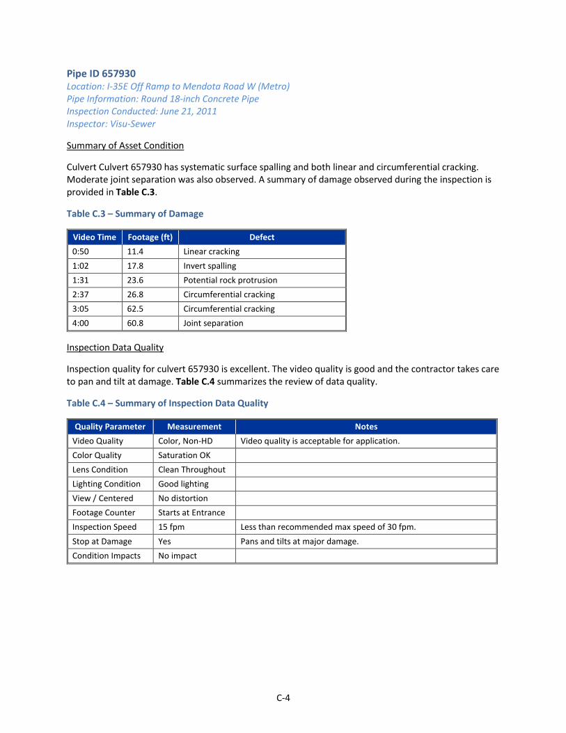
C-4
Pipe ID 657930 Location: I-35E Off Ramp to Mendota Road W (Metro) Pipe Information: Round 18-inch Concrete Pipe Inspection Conducted: June 21, 2011 Inspector: Visu-Sewer
Summary of Asset Condition
Culvert Culvert 657930 has systematic surface spalling and both linear and circumferential cracking. Moderate joint separation was also observed. A summary of damage observed during the inspection is provided in Table C.3.
Table C.3 – Summary of Damage
Video Time Footage (ft) Defect
0:50 11.4 Linear cracking
1:02 17.8 Invert spalling
1:31 23.6 Potential rock protrusion
2:37 26.8 Circumferential cracking
3:05 62.5 Circumferential cracking
4:00 60.8 Joint separation
Inspection Data Quality
Inspection quality for culvert 657930 is excellent. The video quality is good and the contractor takes care to pan and tilt at damage. Table C.4 summarizes the review of data quality.
Table C.4 – Summary of Inspection Data Quality
Quality Parameter Measurement Notes
Video Quality Color, Non-HD Video quality is acceptable for application.
Color Quality Saturation OK
Lens Condition Clean Throughout
Lighting Condition Good lighting
View / Centered No distortion
Footage Counter Starts at Entrance
Inspection Speed 15 fpm Less than recommended max speed of 30 fpm.
Stop at Damage Yes Pans and tilts at major damage.
Condition Impacts No impact

C-5
Pipe ID 545462 Location: Not Located in Geodatabase (Metro) Pipe Information: Round 12-inch Concrete Pipe Inspection Conducted: September 4, 2012 Inspector: Visu-Sewer
Summary of Asset Condition
Culvert 345462 has longitudinal cracking and joint separation. Sag in the invert was observed at 67.4 ft. Contractor could not complete the inspection due to a partial pipe blockage. A summary of damage observed during the inspection is provided in Table C.5.
Table C.5 – Summary of Damage
Video Time Footage (ft) Defect
0:36 0 Longitudinal crack
1:05 8.4 Longitudinal crack
1:16 10.7 Difficult focus, bumpy camera
1:24 17 Possible separated joint
1:28 19.8 Longitudinal crack
1:42 24.7 Longitudinal crack with rust
2:14 32.3 Root intrusion through joint
2:21 39.1 Root intrusion through joint
2:30 47.8 Joint separation and cracking
3:52 67.4 Sag
4:11 76.9 Debris/gravel in invert
4:36 91.4 Sag continues – depth increases
5:14 91.8 Sag continues
5:32 92.8 Debris below water in sag
7:26 97.5 Partial blockage – survey abandoned
Inspection Data Quality
In general, the inspection quality for culvert 545462 is good. Debris in the invert shakes the camera; however, the contractor does stop to document damage. This inspection was abandoned due to a sag in the line. When a survey is abandoned, the contractor should attempt an inspection from the other end of the culvert. Table C.6 summarizes the review of data quality.
Table C.6 – Summary of Inspection Data Quality
Quality Parameter Measurement Notes
Video Quality Color, Non-HD Video quality is acceptable for application.
Color Quality Saturation OK
Lens Condition Clean Throughout Lens remains above water level
Lighting Condition Good lighting
View / Centered No distortion

C-6
Quality Parameter Measurement Notes
Footage Counter Starts at Entrance
Inspection Speed 13 fpm Less than recommended max speed of 30 fpm.
Stop at Damage Yes Pans and tilts at major damage.
Condition Impacts Invert debris Picture shakes due to debris in the invert.
Pipe ID 606307 Location: Mendota Road W and Carmen Lane (Metro) Pipe Information: Round 24-inch Corrugated Metal Pipe Inspection Conducted: April 8, 2016 Inspector: Visu-Sewer
Summary of Asset Condition
Culvert 606307 is in good structural condition, but debris has accumulated. Two pipe deformations and joint deflection was observed. A summary of damage observed during the inspection is provided in Table C.7.
Table C.7 – Summary of Damage
Video Time Footage (ft) Defect
1:02 9.2 Invert debris
1:42 15.6 Deformed pipe
2:31 27.2 Deformed pipe
3:18 33.5 Visible joint
Inspection Data Quality
Culvert 606307 is of good quality. The image shakes due to corrugation in the culvert, but the inspector stops at damage to capture a clear image. Table C.8 summarizes a review of data quality.
Table C.8 – Summary of Inspection Data Quality
Quality Parameter Measurement Notes
Video Quality Color, Non-HD Video quality is acceptable for application.
Color Quality Saturation OK
Lens Condition Clean Throughout
Lighting Condition Good lighting
View / Centered No distortion
Footage Counter Starts at Entrance
Inspection Speed 17 fpm Less than recommended max speed of 30 fpm.
Stop at Damage Yes Pans and tilts at major damage.
Condition Impacts Corrugation impact
Shaking camera due to corrugation
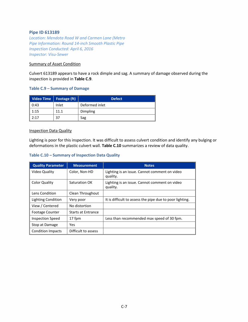
C-7
Pipe ID 613189 Location: Mendota Road W and Carmen Lane (Metro Pipe Information: Round 14-inch Smooth Plastic Pipe Inspection Conducted: April 6, 2016 Inspector: Visu-Sewer
Summary of Asset Condition
Culvert 613189 appears to have a rock dimple and sag. A summary of damage observed during the inspection is provided in Table C.9.
Table C.9 – Summary of Damage
Video Time Footage (ft) Defect
0:43 Inlet Deformed inlet
1:15 11.1 Dimpling
2:17 37 Sag
Inspection Data Quality
Lighting is poor for this inspection. It was difficult to assess culvert condition and identify any bulging or deformations in the plastic culvert wall. Table C.10 summarizes a review of data quality.
Table C.10 – Summary of Inspection Data Quality
Quality Parameter Measurement Notes
Video Quality Color, Non-HD Lighting is an issue. Cannot comment on video quality.
Color Quality Saturation OK Lighting is an issue. Cannot comment on video quality.
Lens Condition Clean Throughout
Lighting Condition Very poor It is difficult to assess the pipe due to poor lighting.
View / Centered No distortion
Footage Counter Starts at Entrance
Inspection Speed 17 fpm Less than recommended max speed of 30 fpm.
Stop at Damage Yes
Condition Impacts Difficult to assess

C-8
Pipe ID 621986 Location: Mendota Road W and Delaware Avenue (Metro) Pipe Information: Round 42-inch Concrete Pipe Inspection Conducted: April 4, 2016 Inspector: Visu-Sewer
Summary of Asset Condition
Culvert 621986 has several separated joints and lateral direction cracking is evident. A summary of damage observed during the inspection is provided in Table C.11.
Table C.11 – Summary of Damage
Video Time Footage (ft) Defect
1:14 26.1 Separated/open joint
1:57 32.5 Separated/open joint
2:54 55.2 Separated/open joint
4:02 86.1 Weeping at the joint
5:35 151 Minor spots of infiltration
6:59 222.1 Hole in pipe at joint, exposed rebar
8:37 224.7 Overflow pipe connection
9:44 240.3 Surface cracks
10:07 259.7 Lateral cracking possible
10:29 284 Cracking
10:57 306.7 Cracking
11:11 316.6 Joint separation
Inspection Data Quality
The inspection for Culvert 621986 is an excellent example of adequate lighting. This inspection is of good quality. Table C.12 summarizes a review of data quality.
Table C.12 – Summary of Inspection Data Quality
Quality Parameter Notes
Video Quality Color, Non-HD
Color Quality Saturation OK
Lens Condition Clean Throughout
Lighting Condition Very poor This is a good example of not being under / over light.
View / Centered No distortion
Footage Counter Starts at Entrance
Inspection Speed 27 fpm Less than recommended max speed of 30 fpm.
Stop at Damage Yes
Condition Impacts No impact

C-9
Pipe ID 621988 Location: Mendota Road W and Delaware Avenue (Metro) Pipe Information: Round 42-inch Concrete Pipe Inspection Conducted: March 29, 2016 Inspector: Visu-Sewer
Summary of Asset Condition
Culvert 621988 is slightly buckled at the crown near footage 13.4. A summary of damage observed during the inspection is provided in Table C.13.
Table C.13 – Summary of Damage
Video Time Footage (ft) Defect
1:09 7.1 Gravel at invert
1:28 13.4 Buckled joint
4:30 95.2 Overgrown invert
Inspection Data Quality
Lighting for the inspection of culvert 621988 was inconsistent throughout. Lighting was poor for the first 17 ft of inspection. Lighting then improved and then gradually became overlight towards the end of the inspection.
Inspectors should consider natural lighting when inspecting culverts. Unlike storm sewers, which start and end at manholes, culverts can be impacted by the angle light enters the culvert. Towards the end of this inspection, the sun appeared to be causing lens flares. Table C.14 summarizes a review of data quality.
Table C.14 – Summary of Inspection Data Quality
Quality Parameter Measurement Notes
Video Quality Color, Non-HD
Color Quality Saturation OK
Lens Condition Clean Throughout
Lighting Condition Dark until 17 ft. Lens flare at the end.
Lighting improves significantly after the 17 ft mark. Towards the end of the culvert, sunlight causes lens flare.
View / Centered No distortion
Footage Counter Starts at Entrance
Inspection Speed 48 fpm Inspection was fast. Contractors should aim for 30 fpm.
Stop at Damage Yes
Condition Impacts No impact

C-10
Pipe ID 683502 Location: East of Mendota Road W and Great River Road (Metro) Pipe Information: Round 15-inch Concrete Pipe Inspection Conducted: April 19, 2016 Inspector: Visu-Sewer
Summary of Asset Condition
Culvert 683502 has several protruding tie rods and minor cracking. A summary of damage observed during the inspection is provided in Table C.15.
Table C.15 – Summary of Damage
Video Time Footage (ft) Defect
1:00 0:00 Circumferential crack
1:31 8.8 Standing water
3:32 13.9 Offset open joint
4:52 21.1 Joint tie rods stick out
5:01 28.8 Joint tie rods stick out
5:30 36.8 Joint tie rods stick out and joint separation
Inspection Data Quality
Data quality for culvert 683502 is good. Lighting is somewhat inconsistent throughout the inspection; however, it is adequate for the inspection. Table C.16 summarizes the review of data quality.
Table C.16 – Summary of Inspection Data Quality
Quality Parameter Measurement Notes
Video Quality Color, Non-HD
Color Quality Saturation OK
Lens Condition Clean Throughout
Lighting Condition Good
View / Centered No distortion
Footage Counter Starts at Entrance
Inspection Speed 18 fpm Less than recommended max speed of 30 fpm.
Stop at Damage Yes
Condition Impacts No impact

C-11
Pipe ID MH 243963A to MH 618616 Location: Not Located in Geodatabase (Metro) Pipe Information: Round 72-inch Concrete Pipe Inspection Conducted: April 6, 2016 Inspector: Visu-Sewer
Summary of Asset Condition
The culvert from MH 243963A to MH 618616 has poor lighting. As a result, no condition assessment could be conducted.
Inspection Data Quality
This inspection camera appears to have no lighting. As a result, inspection data could not be collected. Table C.17 summarizes a review of data quality.
Table C.17 – Summary of Inspection Data Quality
Quality Parameter Measurement Notes
Video Quality Cannot assess Cannot assess due to low lighting
Color Quality Cannot assess Cannot assess due to low lighting
Lens Condition Cannot assess Cannot assess due to low lighting
Lighting Condition No lighting Very poor lighting.
View / Centered Cannot assess
Footage Counter Starts at Entrance
Inspection Speed 37 fpm Inspection was fast. Contractors should aim for 30 fpm.
Stop at Damage No
Condition Impacts Cannot assess

C-12
Pipe ID MH 6570 to MH 6570A Location: Not Located in Geodatabase (District 7) Pipe Information: Round 27-inch Concrete Pipe Inspection Conducted: April 4, 2016 Inspector: Unknown
Summary of Asset Condition
The culvert from manhole 6570 to manhole 6570A has separated joints, cracks and instances of active infiltration. A summary of damage observed during the inspection is provided in Table C.18.
Table C.18 – Summary of Damage
Video Time Footage (ft) Defect
0:42 19.2 Vegetation in the invert
0:58 34.1 Potential spalling in the invert
1:03 35.6 Slight joint separation
1:27 50.8 Infiltration near small tap.
1:39 53.2 Infiltration near small tap
1:59 67.9 Debris in the invert
2:59 100.2 Joint separation
3:42 104.7 Extended longitudinal crack
4:07 108.1 Joint separation
5:22 117.3 Broken joint
6:32 122.2 Mineral deposits at joint
7:42 128.5 Joint separation
7:51 133.5 Mineral deposits at joint
8:37 148.2 Joint separation
8:49 154.1 Longitudinal Cracking
9:05 161.9 Joint separation
9:27 163 Tie rods protruding
9:40 169.7 Joint separation
Inspection Data Quality
This inspection is excellent. Lighting was good and the camera image was clear. Table C.19 summarizes a review of data quality.
Table C.19 – Summary of Inspection Data Quality
Quality Parameter Measurement Notes
Video Quality Color, Non-HD
Color Quality Saturation OK
Lens Condition Clean Throughout
Lighting Condition Good

C-13
Quality Parameter Measurement Notes
View / Centered No distortion
Footage Counter Starts at Entrance
Inspection Speed 17 fpm Less than recommended max speed of 30 fpm.
Stop at Damage Yes
Condition Impacts No impact
Pipe ID MH 2026 to MH 5025 Location: Not Located in Geodatabase (District 7) Pipe Information: Round 18-inch Concrete Pipe Inspection Conducted: October 22, 2014 Inspector: Unknown
Summary of Asset Condition
The culvert from manhole 2026 to manhole 5025 has joint separation and areas of active infiltration. A summary of damage observed during the inspection is provided in Table C.20.
Table C.20 – Summary of Damage
Video Time Footage (ft) Defect
0:49 0 Debris at invert
3:33 6 Longitudinal cracking
3:54 16.1 Joint corroding
4:16 24 Joint separation
4:38 31.09 Joint separation
5:16 47.08 Debris at invert
5:25 51.08 Change in water level
5:42 63.04 Joint separation
5:57 64.1 Infiltration – weeping. Debris in invert.
6:01 68.01 Infiltration – weeping. Debris in invert.
6:28 79.08 Infiltration – weeping. Debris in invert.
7:07 100.06 Infiltration – weeping.
7:50 113.01 Infiltration – weeping.
8:27 140.07 Infiltration – weeping.
9:00 160.11 Infiltration – weeping.
9:11 164.08 Debris at invert
9:29 176.08 Infiltration – weeping.
9:39 179.1 Roots protruding from joint
10:24 209.04 Infiltration – weeping.
10:56 227 Debris at invert
11:38 254 Infiltration – weeping.
11:52 262.11 Debris at invert
12:14 275.01 Longitudinal cracking
12:32 288.05 Infiltration – weeping.
12:57 288.08 Joint separation

C-14
Inspection Data Quality
Inspection quality was excellent. This culvert had several locations where infiltration was weeping into the culvert. The inspector took care to stop at these locations and collect an image. Table C.21 summarizes a review of data quality.
Table C.21 – Summary of Inspection Data Quality
Quality Parameter Measurement Notes
Video Quality Color, Non-HD
Color Quality Saturation OK
Lens Condition Clean Throughout
Lighting Condition Good
View / Centered No distortion
Footage Counter Starts at Entrance
Inspection Speed 21 fpm Less than recommended max speed of 30 fpm.
Stop at Damage Yes
Condition Impacts No impact
Conclusions
Pertinent conclusions from the review of inspection video are as follows:
A quality control review of inspection video should evaluate the following nine components of quality: video quality; color quality; lens condition; lighting; centered view; footage counter accuracy; inspection speed; documentation at damage; and, condition impacts to quality.
A reasonable quality camera should be able to provide video at a minimum resolution of 650 x 480 pixels. This resolution is roughly equivalent to a standard definition DVD.
Culverts are constructed in a variety of diameters and materials. The inspection camera should have lighting that is appropriate to the culvert attributes.
Maintaining a centered view of the camera is essential when evaluating culvert ovality. If the camera is not centered, the culvert may falsely appear out of round.
Providing an accurate footage count is essential to allow an inspector to correlate damage at grade to damage in the culvert.
Industry standards recommend that inspections should not exceed 30 fpm.
If significant debris is present in the invert and the culvert has not been cleaned, condition may be difficult to evaluate because the camera shakes while it traverses the culvert. The inspector should take care to completely stop the camera and allow it to focus on a defect before continuing the inspection.
Culvert inspections can be impacted by the sun. Sun shining into a camera lens may create lens flares that obscure damage. Inspectors should consider the position of the sun during an early morning or late afternoon inspection. If the sun is impacting the inspection, consider conducting the inspection from the opposite end of the culvert so the sun is behind the camera lens.

APPENDIX D SUMMARY OF FIELD INSPECTIONS
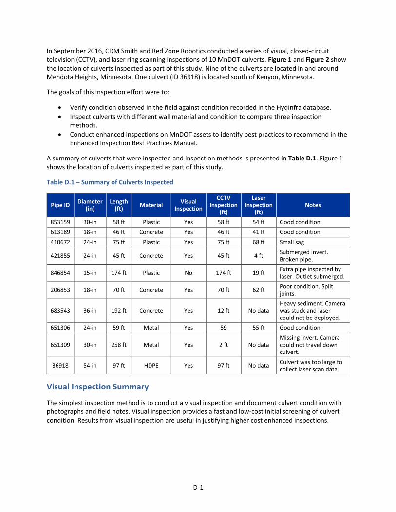
D-1
In September 2016, CDM Smith and Red Zone Robotics conducted a series of visual, closed-circuit television (CCTV), and laser ring scanning inspections of 10 MnDOT culverts. Figure 1 and Figure 2 show the location of culverts inspected as part of this study. Nine of the culverts are located in and around Mendota Heights, Minnesota. One culvert (ID 36918) is located south of Kenyon, Minnesota.
The goals of this inspection effort were to:
Verify condition observed in the field against condition recorded in the HydInfra database.
Inspect culverts with different wall material and condition to compare three inspection methods.
Conduct enhanced inspections on MnDOT assets to identify best practices to recommend in the Enhanced Inspection Best Practices Manual.
A summary of culverts that were inspected and inspection methods is presented in Table D.1. Figure 1 shows the location of culverts inspected as part of this study.
Table D.1 – Summary of Culverts Inspected
Pipe ID Diameter
(in) Length
(ft) Material
Visual Inspection
CCTV Inspection
(ft)
Laser Inspection
(ft) Notes
853159 30-in 58 ft Plastic Yes 58 ft 54 ft Good condition
613189 18-in 46 ft Concrete Yes 46 ft 41 ft Good condition
410672 24-in 75 ft Plastic Yes 75 ft 68 ft Small sag
421855 24-in 45 ft Concrete Yes 45 ft 4 ft Submerged invert. Broken pipe.
846854 15-in 174 ft Plastic No 174 ft 19 ft Extra pipe inspected by laser. Outlet submerged.
206853 18-in 70 ft Concrete Yes 70 ft 62 ft Poor condition. Split joints.
683543 36-in 192 ft Concrete Yes 12 ft No data Heavy sediment. Camera was stuck and laser could not be deployed.
651306 24-in 59 ft Metal Yes 59 55 ft Good condition.
651309 30-in 258 ft Metal Yes 2 ft No data Missing invert. Camera could not travel down culvert.
36918 54-in 97 ft HDPE Yes 97 ft No data Culvert was too large to collect laser scan data.
Visual Inspection Summary
The simplest inspection method is to conduct a visual inspection and document culvert condition with photographs and field notes. Visual inspection provides a fast and low-cost initial screening of culvert condition. Results from visual inspection are useful in justifying higher cost enhanced inspections.

D-2
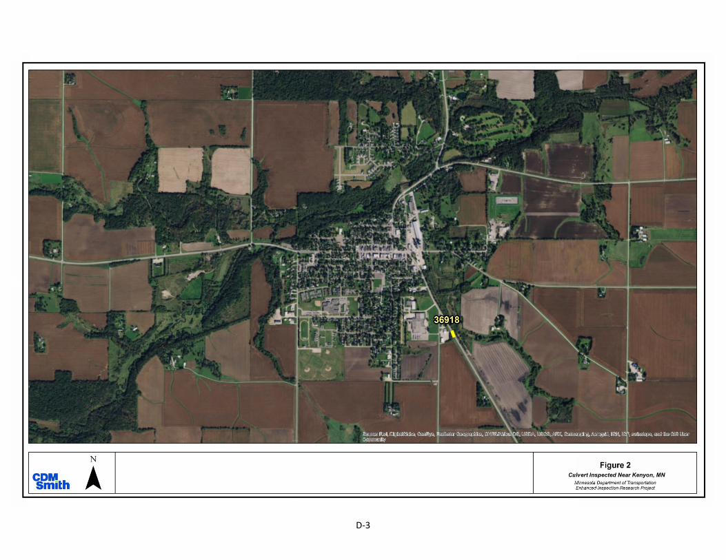
D-3

D-4
Methodology
CDM Smith conducted visual inspections of culverts on September 28, 2016. The inspection team included two staff members equipped with digital cameras, measuring tape, high powered spotlights, and a hard copy inspection form.
The six-step visual inspection procedure is as follows:
1. Field locate each culvert’s inlet and outlet. Document site condition at the inlet and outlet. 2. Inspect road condition along the culverts alignment. Identify fractures or sinks in the road
surface that may correlate to damage in the culvert. 3. Measure culvert geometry at the inlet. Culvert geometry includes culvert height, culvert width,
depth of cover, distance to joints, and distance visible inside the culvert. Often, the entire culvert was visible; however, due to poor lighting, the ‘distance visible’ measurement is the distance in which condition could be accurately assessed by the inspector.
4. Document condition at the culvert inlet. Take photographs of internal condition. 5. Measure culvert geometry at the culvert outlet. 6. Document condition at the culvert outlet. Take photographs of internal condition.
Nine of the culverts were 36-inch or smaller. Consequently, person entry was not possible. The 54-inch culvert located in Kenyon, Minnesota (ID 36918) was large enough to enter and inspect. Person entry was conducted at this culvert.
Results
Visual inspection Limitations
Visual inspections are low cost, but data obtained from this type of inspection are limited. Key limitations include:
Nine of the ten culverts are smaller than 36-inch diameter. Entering the culvert for visual, internal inspection was not possible. Inspection at these culverts were limited to about 5 to 10 feet at the inlet and outlet of the culvert. A detailed documentation of internal condition beyond 10 feet from an inlet/outlet was not possible.
It is difficult to inspect the wall condition of black, plastic pipe. Even with high powered lighting, gouges in the pipe wall could not be easily assessed.
The location and condition of storm drain connections could not be adequately inspected from the culvert inlet/outlet.
Three culverts (ID 421855, 651309, and 113292) had submerged inlets. Visual inspection of the submerged culvert sections was not possible.
Data Obtained from Visual Inspections
Major damage to a culvert, such as a partial collapse, can be identified from a visual inspection. If additional data is needed to design a repair, visual inspections are helpful in justifying the cost of an enhanced inspection.
Figure 3 – Visual Inspection of Culvert ID 410672 indicates no major deformations impacting the culvert cross section.

D-5
If the inspector can see to the end of a culvert, a limited assessment of culvert ovality could be conducted. The inspector can view the culvert’s silhouette and major deformations can be confirmed (Figure 3). This approach identifies deformations, but cannot quantify the extent of deformation (i.e., percentage of cross section reduction).
When a contractor is retained to conduct a CCTV inspection, often inlet/outlet condition and the condition of a road over the culvert are not inspected (Figure 4). Visual inspection is helpful in documenting site conditions associated with culvert damage.
Visual inspections were helpful in identifying operations and maintenance concerns. Culvert ID 206853 was found to have sediment deposits which likely impact capacity.
Enhanced Inspection Summary
Enhanced inspections, such as CCTV and laser ring scanning inspections, provide quantifiable data on a culverts geometry and condition. These inspections, however, are more difficult to coordinate and more expensive than visual inspections. When the right technology is used in the right location, enhanced inspections provide valuable data that can facilitate asset management decisions.
Methodology
Red Zone Robotics conducted high definition CCTV camera inspections of ten culverts on September 19, 2016. Seven of the ten culverts also received laser scan inspection. Laser scan could not be conducted on three culverts for the following reasons:
Culvert ID 683543 was full of sediment (Figure 5). The camera could not drive over the sediment deposits.
Culvert ID 651309 was missing its invert. The camera’s wheels could not navigate the uneven surface.
Culvert ID 36918 was 56 inches in diameter. The culvert diameter exceeded the maximum conduit size for the laser unit.
The enhanced inspection procedure was as follows:
1. The contractor reviewed site information to identify traffic controls requirements.
2. When on site, the contractor assessed light in the culverts. If the sun impacted video quality, the contractor hung a tarp over the culvert outlet and used the camera’s on-board lighting (Figure 6).
Figure 4 – A crack was observed in the road above Culvert ID 206853. This crack correlates with the culvert alignment.
Figure 5 –Culvert ID 206853 was full of sediment. The CCTV camera could not inspect this culvert.
Figure 6 – A tarp was hung at the culvert’s outlet to control camera lighting.

D-6
3. The contractor deployed the CCTV camera in the culvert. Video was recorded and the contractor documented internal condition using Pipe Assessment Certification Program (PACP) standards.
4. The contractor deployed the laser ring scanner to collect culvert profile information. 5. CCTV video and laser ring data were sent to the contractor’s data processing center. Data
processing for this project took four weeks. 6. A summary report and inspection data was then sent to CDM Smith for review. Excerpts from
this summary report are included as attachments to this appendix. 7. CDM Smith conducted a quality review of enhanced inspection data. Criteria to evaluate data
quality included:
Does the operator stop the inspection camera at defects?
Is the video quality acceptable?
Does color appear to be adjusted and accurate?
Does the lens remain clean throughout the inspection?
Is the culvert adequately lit during inspection and does the footage counter appear to be accurate?
Enhanced Inspection Limitations
While enhanced inspections provide detailed condition information, these methods also had limitations, including:
Laser ring inspection units are designed and calibrated to accurately measure culverts of a certain diameter. That is, a small diameter culvert laser will not have the power to inspect a large diameter culvert. Conversely, a large diameter culvert laser will be too large to deploy in a smaller culvert.
The inspection crawler has difficulty navigating inverts
that are in poor condition (Figure 7). Contractors are
hesitant to inspect culverts when there is a risk of getting
equipment stuck.
Laser scan data requires several weeks to process.
Approximately 300 lf of culvert were scanned. Results
were received four weeks after field work was complete.
For this study, a quick turnaround was not required. If
laser scan results are needed quickly to meet a project’s
schedule, CDM Smith recommends discussing time
constraints prior to retaining a contractor.
Laser scan data is expensive. Red Zone Robotics’ cost to mobilize for this project was $8,500 and inspection was approximately $6.50 per linear foot. To justify the large mobilization cost, CDM Smith recommends retaining contractors to inspect many culverts under a single contract.
Figure 7 – Culvert ID 651309 had a severely corroded invert. The inspection camera could not travel through the culvert.
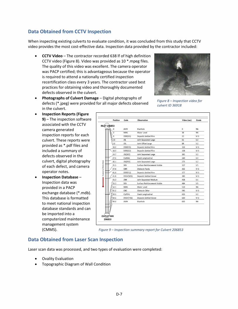
D-7
Data Obtained from CCTV Inspection
When inspecting existing culverts to evaluate condition, it was concluded from this study that CCTV video provides the most cost-effective data. Inspection data provided by the contractor included:
CCTV Video – The contractor recorded 638 lf of high definition CCTV video (Figure 8). Video was provided as 10 *.mpeg files. The quality of this video was excellent. The camera operator was PACP certified; this is advantageous because the operator is required to attend a nationally certified inspection recertification class every 3 years. The contractor used best practices for obtaining video and thoroughly documented defects observed in the culvert.
Photographs of Culvert Damage – Digital photographs of defects (*.jpeg) were provided for all major defects observed in the culvert.
Inspection Reports (Figure 9) – The inspection software associated with the CCTV camera generated inspection reports for each culvert. These reports were provided as *.pdf files and included a summary of defects observed in the culvert, digital photography of each defect, and camera operator notes.
Inspection Database – Inspection data was provided in a PACP exchange database (*.mdb). This database is formatted to meet national inspection database standards and can be imported into a computerized maintenance management system (CMMS).
Data Obtained from Laser Scan Inspection
Laser scan data was processed, and two types of evaluation were completed:
Ovality Evaluation
Topographic Diagram of Wall Condition
Figure 8 – Inspection video for culvert ID 36918
Figure 9 – Inspection summary report for Culvert 206853
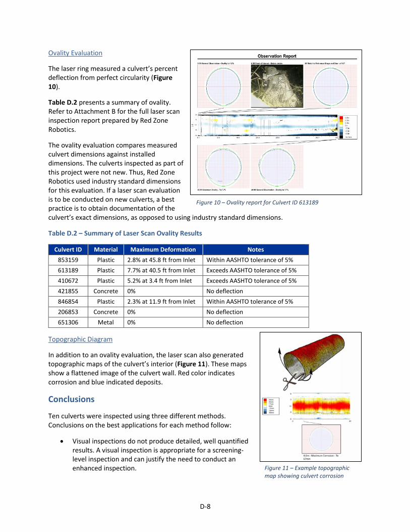
D-8
Ovality Evaluation
The laser ring measured a culvert’s percent deflection from perfect circularity (Figure 10).
Table D.2 presents a summary of ovality. Refer to Attachment B for the full laser scan inspection report prepared by Red Zone Robotics.
The ovality evaluation compares measured culvert dimensions against installed dimensions. The culverts inspected as part of this project were not new. Thus, Red Zone Robotics used industry standard dimensions for this evaluation. If a laser scan evaluation is to be conducted on new culverts, a best practice is to obtain documentation of the culvert’s exact dimensions, as opposed to using industry standard dimensions.
Table D.2 – Summary of Laser Scan Ovality Results
Culvert ID Material Maximum Deformation Notes
853159 Plastic 2.8% at 45.8 ft from Inlet Within AASHTO tolerance of 5%
613189 Plastic 7.7% at 40.5 ft from Inlet Exceeds AASHTO tolerance of 5%
410672 Plastic 5.2% at 3.4 ft from Inlet Exceeds AASHTO tolerance of 5%
421855 Concrete 0% No deflection
846854 Plastic 2.3% at 11.9 ft from Inlet Within AASHTO tolerance of 5%
206853 Concrete 0% No deflection
651306 Metal 0% No deflection
Topographic Diagram
In addition to an ovality evaluation, the laser scan also generated topographic maps of the culvert’s interior (Figure 11). These maps show a flattened image of the culvert wall. Red color indicates corrosion and blue indicated deposits.
Conclusions
Ten culverts were inspected using three different methods. Conclusions on the best applications for each method follow:
Visual inspections do not produce detailed, well quantified results. A visual inspection is appropriate for a screening-level inspection and can justify the need to conduct an enhanced inspection.
Figure 10 – Ovality report for Culvert ID 613189
Figure 11 – Example topographic map showing culvert corrosion

D-9
CCTV inspections generate the most cost-effective data. Pipe damage can be identified andassociated with a footage location within the culvert. Culvert deformations and corrosion, whichare better quantified by laser ring scanning, can often be identified by CCTV inspection.
Laser Ring Scanning inspections quantify the extent of a culvert’s deformation or corrosion.While this inspection is expensive, the results are precise. This precision may be useful wheninvestigating out-of-tolerance deflections after construction.

APPENDIX E GUIDE SPECIFICATIONS
E-1
S-# (####) CCTV INSPECTION OF CULVERTS
Provide the necessary labor, equipment, and services required, and perform closed-circuit television (CCTV) inspection as necessary to document the condition of culverts, connections and associated hydraulic structures as delineated in these Contract Documents. Conduct all inspection work in accordance with these Contract Documents.
S-#.1 Contractor shall provide the following:
A) Provide mobilization and demobilization of inspection equipment, trained engineering technicians and camera crews as required to complete the requirements of these Contract Documents.
B) Provide means, access the site and complete the set-up and deployment of inspection equipment into the culvert to be inspected. Remove culvert features, such as metal debris guards and safety grates, as required to access the culvert.
C) Provide labor, equipment and materials required and collect inspection data for the culverts delineated in these Contract Documents.
D) Provide labor to restore any features that were removed to access the culvert after inspections are complete. Restore the site to its pre-inspection condition, and in accordance with Specification 1407 – Final Cleanup.
E) Complete a daily log of inspection activities.
F) Provide the labor, equipment and materials required to post-process inspection data in accordance with this Specification.
G) Prepare and deliver the inspection data and associated reports to MnDOT in accordance with this Section.
S-#.2 The following CCTV camera and video requirements shall be met:
A) The CCTV camera shall be specifically designed and constructed for culvert inspection with a capacity for radial viewing (360°) and of proper height to allow inspections of the culvert, storm drain connections and associated hydraulic structures. Televising shall be accomplished via remotely operated camera.
B) The radial view camera shall be solid state color and have remote control of the rotational lens. The camera shall be capable of viewing the complete circumference of the culvert. The camera shall be operable in 100% humidity conditions. Cameras incorporating mirrors for viewing side or using exposed rotating heads are not acceptable. The camera lens shall be an auto-iris type with remote controlled manual override. The camera shall record video imagery to a resolution no less than 650 x 480 pixels.
C) The camera light head shall include a high-intensity side viewing lighting system to allow for peripheral lighting. Lighting for the camera shall illuminate the entire periphery of the sewer for a distance of at least 30 ft ahead of the camera. Lighting shall be designed to avoid over-lighting the culvert and obscuring culvert wall condition. The lights shall be operable in 100% humidity conditions.

E-2
D) The camera shall be equipped with a calibrated distance meter that provides a digital readout on the video monitor. Measurements will be accurate to one foot per 100-ft of inspected culvert.
E) Digital video shall be defined as ISO-MPEG Level 2 (MPEG-2) coding having a resolution no less than 640 pixels (x) by 480 pixels (y) and an encoded frame rate of 29.97 frames per second. The digital recordings shall include one of the following: video or audio/video information that accurately reproduces the original picture and sound of the video inspection. The video portion of the digital recording shall be free of electrical interference and shall produce a clear and stable image. The audio portion shall be sufficiently free of background and electrical noise as to produce an oral report that is clear and discernable. Separate digital recordings shall be made for each culvert inspected and properly identified, via on-screen display and voice over recordings.
F) Include the following on-screen identification for each inspection: Culvert Identifier, Direction of Inspection (upstream or downstream), Distance of Survey (linear feet), Owner (e.g., MnDOT), Date, Time.
G) Include the following as part of the computerized or vocal audio narrative and record on the audio portion of the video: Describe observed defects, describe the location of storm drain connections, describe unusual conditions observed, identify points where digital still photographs are taken.
H) All inspections shall be coded to identify operations and maintenance concerns, damage and construction features.
I) If inspection video or audio recording quality is poor, MnDOT has the right to reject the recording and request that it is re-done at no additional cost to the Owner.
S-#.3 Contractor shall complete the following activities under this contract:
A) Attend and participate in a pre-field work meeting with the Owner, upon request. This meeting will be held in the field or via telephone. Schedule, implementation planning and deliverable expectations will be discussed.
B) Protect and restore MnDOT, public and private property in accordance with MnDOT Specification 1712 – Protection and Restoration of Property. Restore the site to pre-inspection condition within seven calendar days after field work is complete.
C) Access the site to deploy inspection equipment. Access may be made by truck or all terrain vehicle (ATV).
D) Deploy and operate the inspection equipment per requirements of the Contract Documents. Allow MnDOT field representation to review video inspection data on-site and make recommendations for improvement. Make operational changes as required to accommodate Field Representative’s recommendations for improvement.
E) Inspection equipment shall be calibrated prior to inspection. Calibration includes color correction, testing lighting inside the culvert, cleaning the camera lens, and setting footage to 0 at the culvert inlet / outlet. Contractor shall block the inlet / outlet with a tarp during inspection to control ambient lighting, as needed to obtain clear video documentation. The

E-3
camera shall be centered horizontally at the center of the culvert and oriented to avoid image distortion.
F) Complete a daily inspection log to detail the on-site work completed each day.
G) Document all internal culvert inspections via digital video recordings, inspection logs and digital photographs.
H) Measurement for location of defects and actual length of culvert shall be by means of calibrated meter on the camera with a digital readout on the video monitor. This readout shall be included in the video recording. Measurement will be accurate to one foot per 100 ft of inspected culvert. The defect database shall track length to defect by referencing the video frame number of each observed defect.
I) The camera shall be directed through the culvert at a uniform and slow rate. In no case, shall the camera record while moving at a speed greater than 30 feet per minute.
J) The camera operator shall stop, pan and zoom at any observed culvert damage. The camera operator shall also stop, pan and zoom at each storm drain connection and shall pan and zoom beyond blockages and obstructions.
K) If inspection equipment cannot pass through the entire culvert, reset the equipment at the opposite inlet / outlet and attempt inspection from the opposite direction.
S-#.4 Contractor shall submit the following data:
A) Prior to mobilization, prepare and submit an inspection plan that provides detail on how the inspection will be implemented efficiently and safely. At a minimum, the plan shall: list strategy to access each culvert, identify equipment staging areas, identify work that will be conducted each day, identify locations requiring traffic control and discuss proposed traffic control methods, discuss safety issues and concerns, discuss proposed methods for managing safety risks, list permits that are required, and present the project schedule (including start and completion dates). The plan shall also include:
B) Summarize access issues that were identified and measures that will be taken to address issues.
C) Submit a copy of Health and Safety information in accordance with Section 1706 – Employee Health and Welfare.
D) Provide a traffic control plan in accordance with Section 1710 – Traffic Control Devices.
E) Provide a temporary flow control plan that describes the method of flow control and set-up location of flow control equipment.
F) Provide a project schedule in accordance with Section 1803 – Progress Schedule.
G) Provide inspection data to MnDOT via and external hard drive or USB flash drive with a complete set of inspection data included on the drive. The data shall specifically include video indexing of all inspections. Data submitted on the hard drive / flash drive shall include:

E-4
a. Provide a database file summarizing all observed defects, locations and video frame reference number. The database file shall be in a format that is compatible with inspection review software [UPDATE WITH PREFERRED REVIEW SOFTWARE AND THE CURRENT VERSION NUMBER].
b. Provide video files for each culvert. Video files shall include a running footage counter and audio or text based commentary.
c. Submit an inspection summary for each culvert as a *.pdf file. The summary shall identify culvert attributes, defects that were observed and footage from culvert inlet / outlet. [USE ONE OF THE FOLLOWING OR OMIT BOTH] Upon request, and prior to inspection, provide MnDOT with an example summary. [OR] Prior to inspection, MnDOT will provide an example summary which should be followed when preparing the summary.
d. Provide screen captures of all structural damage in a JPEG (*.jpeg) format.
S-#.5 Payment shall be measured based on the inspection camera’s on-board footage counter. Footage of a culvert that is not inspected per specifications due to quality control issues will not be included in the measurement of completed work. Blockages / obstructions in the culvert may be deemed acceptable footage as long as efforts are made to view the culvert form the opposite end of said culvert and accompanied by zooming the camera lens to view the majority of the pipe beyond the blockage / obstruction. MnDOT field representatives will determine if footage and zooming of culverts is an acceptable inspection.
S-#.6 MnDOT will pay only for work completed with video, audio, digital and/or hard copy records that are acceptable per the Contract Documents.
The Department will pay for CCTV inspection based on the following schedule [FILL IN XX BELOW WITH APPROPRIATE TEXT]:
Item No: Item: Unit:
XXXX CCTV Inspection of Culvert, XX-IN per linear foot
E-5
S-# (####) MULTIPLE SENSOR ROBOTIC INSPECTION OF CULVERTS
Provide the necessary labor, equipment, and services required, and perform a multiple sensor robotic inspection as necessary to document the condition of culverts, connections and associated hydraulic structures as delineated in these Contract Documents. Conduct all inspection work in accordance with these Contract Documents. S-#.1 Contractor shall provide the following:
H) Provide mobilization and demobilization of inspection equipment, trained engineering
technicians and operator crews as required to complete the requirements of these Contract
Documents.
I) Provide means, access the site and complete the set-up and deployment of inspection
equipment into the culvert to be inspected. Remove culvert features, such as metal debris
guards and safety grates, as required to access the culvert.
J) Provide labor, equipment and materials required and collect inspection data for the culverts
delineated in these Contract Documents. Multiple sensor robotic inspection shall include:
[SELECT THE APPLICABLE SENSORS TO USE WITH THIS INSPECTION. REQUIRING
UNNECESSARY SENSORS WILL INCREASE COST] laser profiling, sonar profiling, inclinometer
measurement.
K) Provide labor to restore any features that were removed to access the culvert after
inspections are complete. Restore the site to its pre-inspection condition, and in accordance
with Specification 1407 – Final Cleanup.
L) Complete a daily log of inspection activities.
M) Provide the labor, equipment and materials required to post-process inspection data in
accordance with this Specification.
N) Prepare and deliver the inspection data and associated reports to MnDOT in accordance
with this Section.
S-#.2 The following multiple sensor inspection equipment requirements shall be met: [SELECT APPLICABLE SENSORS TO USE WITH THIS INSPECTION. REQUIRING UNNECESSARY SENSORS MAY INCREASE COST]
A) Provide a laser profiling unit that can measure ovality to at least 0.1% deflection from round
and provide 2-D profiling as specified herein.
B) Provide a sonar scanning unit that can provide below-water profiling and debris
documentation as specified herein.
C) Provide an inclinometer that can provide continual incline measurements to at least 0.1%
slope and as specified herein.
S-#.3 Contractor shall complete the following activities under this contract: [MODIFY
A) Attend and participate in a pre-field work meeting with the Owner, upon request. This
meeting will be held in the field or via telephone. Schedule, implementation planning and
deliverable expectations will be discussed.

E-6
B) Protect and restore MnDOT, public and private property in accordance with MnDOT
Specification 1712 – Protection and Restoration of Property. Restore the site to pre-
inspection condition within seven calendar days after field work is complete.
C) Access the site to deploy inspection equipment. Access may be made by truck or all terrain
vehicle (ATV).
D) Deploy and operate the inspection equipment per requirements of the Contract Documents.
Allow MnDOT field representation to review video inspection data on-site and make
recommendations for improvement. Make operational changes as required to
accommodate Field Representative’s recommendations for improvement.
E) Inspection equipment shall be calibrated in accordance to manufacturer protocols prior to
mobilization.
F) Complete a daily inspection log to detail the on-site work completed each day.
G) Collect laser profile measurements at a sufficient interval to generate reports as specified
herein.
H) Collect continual sonar measurements for all standing water and submerged areas of the
culvert.
I) Collect continual inclinometer measurements throughout the culvert.
J) If inspection equipment cannot pass through the entire culvert, reset the equipment at the
opposite inlet / outlet and attempt inspection from the opposite direction.
S-#.4 Contractor shall submit the following data:
A) Prior to mobilization, prepare and submit an inspection plan that provides detail on how the
inspection will be implemented efficiently and safely. At a minimum, the plan shall: list
strategy to access each culvert, identify equipment staging areas, identify work that will be
conducted each day, identify locations requiring traffic control and discuss proposed traffic
control methods, discuss safety issues and concerns, discuss proposed methods for
managing safety risks, list permits that are required, and present the project schedule
(including start and completion dates). The plan shall also include:
B) Summarize access issues that were identified and measures that will be taken to address
issues.
C) Submit a copy of Health and Safety information in accordance with Section 1706 – Employee
Health and Welfare.
D) Provide a traffic control plan in accordance with Section 1710 – Traffic Control Devices.
E) Provide a temporary flow control plan that describes the method of flow control and set-up
location of flow control equipment.
F) Provide a project schedule in accordance with Section 1803 – Progress Schedule.
G) Provide inspection data to MnDOT via and external hard drive or USB flash drive with a
complete set of inspection data included on the drive. The data shall specifically include
video indexing of all inspections. Data submitted on the hard drive / flash drive shall include:
a. Laser Scan Inspection Documentation [INCLUDE IF SPECIFYING LASER SCANNING.
OMIT ANY EVALUATIONS THAT ARE NOT NEEDED. EXTRA EVALUATIONS MAY
INCREASE PROCESSING TIME AND COST]

E-7
i. Provide a report summarizing results of the laser scan inspection. The report
shall include documentation of the culvert’s true diameter throughout,
ovality (per ASTM F1216), x/y diameter, maximum diameter, minimum
diameter.
ii. Segments or areas revealing deflection in horizontal alignment greater than
2% must be identified in the report.
iii. Where the presence of flow in the pipeline requires interpolation and
estimation calculations to fill data gaps and complete the full circumference
view, the method and calculations used to support these assumptions shall
be presented. Sonar profiling or other data sources, such as as-built data, if
used for these calculations shall be identified in the report.
iv. The report shall provide a 2-D representation of an integrated overview of
pipe wall thickness loss or increase data revealed from laser scanning,
presented in a color-coded format as an unrolled (flat) illustration of the
pipe condition above the waterline over the length of the inspection
segment. The pipe interior is to be flattened into a graphic whose y-axis
represents pipe diameter; whose x-axis represents pipe length and whose
color represents deviations from expected values indicating a gradation and
severity of corrosion or buildup. Measured pipe internal diameter that
coincides with expected values must be coded in a color that positively
identifies and differentiates the measurement of the expected values from
pipe wall loss or increase.
v. The report shall provide a 2-D representation of culvert ovality and
deviation from concentricity. Measured internal diameters that coincide
with expected values must be coded in a color that positively identifies and
differentiates measurements of diameters that deviate from concentricity.
Quantify ovality deformations as % of expected cross section.
b. Sonar Scan Inspection Documentation [INCLUDE IF SPECIFYING SONAR]
i. High resolution, cross section scans shall be recorded continuously by
SONAR equipment. Documentation for sonar readings must include a
graphical display of sediment depth and percent cross sectional area
reduction based on a full flowing culvert. Present estimated quantity (cy) of
sediment. SONAR data shall be provided in a Microsoft Excel data table.
ii. Where sediment / debris volume estimates are given, the volume
calculation accuracy shall be a minimum of 92% for culverts between 6-in to
54-in diameter.
c. Inclinometer Measurement Documentation [INCLUDE IF SPECIFYING AN
INCLINOMETER]
i. Provide a plot of inclinometer results. The x-axis correlates distance from
the culvert inlet. The y-axis correlates to elevation / slope. Provide
inclinometer slope results in a Microsoft Excel data table.

E-8
H) Provide a license for any proprietary viewing software that is required for MnDOT to review
and manipulate raw data collected by the sensors. [INCLUDE IF NEED RAW DATA]
S-#.5 Payment shall be measured based on the footage of data evaluated and submitted in inspection documentation reports. Footage of a culvert that is not inspected per specifications due to quality control issues or blockages in the culvert will not be included in the measurement of completed work.
S-#.6 MnDOT will pay only for work completed with data and final reports that are acceptable per the Contract Documents.
The Department will pay for multiple sensor inspection inspection based on the following schedule [FILL IN XX BELOW WITH APPROPRIATE TEXT]:
Item No: Item: Unit: XXXX Multiple Sensor Robotic Inspection of Culvert, XX-IN per linear foot