Engineering Report Wastewater Treatment Modifications
44
Dra 32001 32nd Avenue South, Suite 100 Federal Way, Washington 98001 253-835-6400 Engineering Report Wastewater Treatment Modifications September 2019 Prepared for Production Plating 4412 Russel Road Mukilteo, Washington 98275 KJ Project No. 1896032*00 10/16/2019
Transcript of Engineering Report Wastewater Treatment Modifications

Dra
32001 32nd Avenue South, Suite 100 Federal Way, Washington 98001
253-835-6400
Engineering Report
Wastewater Treatment Modifications
September 2019
Prepared for
Production Plating 4412 Russel Road
Mukilteo, Washington 98275
KJ Project No. 1896032*00
10/16/2019

Engineering Report, Production Plating, Inc. i w:\2018\1896032.00_productionplating_er\2019_eng_rpt\_production plating er v2.wp.docx
Table of Contents
List of Tables ............................................................................................................................... ii
List of Figures.............................................................................................................................. ii
List of Appendices ....................................................................................................................... ii
Acronyms and Abbreviations ...................................................................................................... iii
Section 1: Executive Summary .................................................................. 1-1
Section 2: WAC 173-240-130 Requirements .............................................. 2-1
Section 3: Selective Metal Ion Exchange .................................................. 3-1
3.1 Introduction ....................................................................................... 3-1 3.2 Phase I Description ........................................................................... 3-1 3.3 Phase 2 Description .......................................................................... 3-2 3.4 Phase 3 Description .......................................................................... 3-2 3.5 Ion Exchange System ....................................................................... 3-2
3.5.1 Resin Performance and Column Regeneration Frequency ............................................................................. 3-2
3.5.2 Process Controls .................................................................... 3-3 3.5.3 System and Resin Hydraulics ................................................. 3-3
Table of Contents (cont'd)
Engineering Report, Production Plating, Inc. ii w:\2018\1896032.00_productionplating_er\2019_eng_rpt\_production plating er v2.wp.docx
List of Tables
2.1 Water Consumption 2.2 Monitored Constituents in Process Water Discharge 2.3 Discharge Limits
List of Figures
1 Site Plan 2 Existing Wastewater Treatment Layout
List of Appendices
A Treatment System Operations Manual B Treatment System Drawings C Big Gulch Treatment Plant Biosolids Reports
Engineering Report, Production Plating, Inc. iii w:\2018\1896032.00_productionplating_er\2019_eng_rpt\_production plating er v2.wp.docx
Acronyms and Abbreviations
ACT Advanced Chemical Technologies, Inc. City City of Mukilteo CO2 carbon dioxide Ecology Washington State Department of Ecology EDTA ethylene di-tetra-acetic acid EPA United States Environmental Protection Agency eq/L equivalents per liter gpd gallons per day gpm gallons per minute mg/L milligrams per liter NEPA National Environmental Policy Act NPDES National Pollutant Discharge Elimination System P&ID process and instrumentation diagram POTW publicly-owned treatment works ppb parts per billion PPI Production Plating, Inc. psi pounds per square inch PVC polyvinyl chloride RCRA Resource Conservation and Recovery Act SEPA State Environmental Policy Act SIC Standard Industrial Classification sq. ft. square feet TSDF Treatment, Storage, and Disposal Facility TTO Total Toxic Organic Compound WAC Washington Administrative Code

Engineering Report, Production Plating, Inc. Page 1-1 w:\2018\1896032.00_productionplating_er\2019_eng_rpt\_production plating er v2.wp.docx
Section 1: Executive Summary
Production Plating, Inc.’s (PPI) two main, proposed pretreatment systems are pH control and filtration of metal bearing rinse water prior to selective metal ion exchange and pH control of non-metal bearing rinse water (i.e., categorical discharge).
This Engineering Report (Report) responds to the Washington State Department of Ecology’s (Ecology) requirement that a discharge application include a Professional Engineering review of the wastewater treatment systems according to Washington State regulations [Washington Administrative Code (WAC) 173-240]. PPI requested a conceptual level Professional Engineering Report as allowed by WAC 173-240-110(5) for industrial wastewater treatment systems as customarily accepted by Ecology. A conceptual level report is compatible with the simplicity of the treatment systems and historical high compliance rate of similar systems.
The primary findings of this Report include the following:
1. The treated wastewater quality will have a very high assurance of permit compliance.
2. The selected treatment technologies will consistently achieve a heavy metal discharge concentration well below the discharge permit limits and pH values within the prescribed limits.
3. The pretreatment system will have negligible impact on the City of Mukilteo’s (City) Publicly-Owned Treatment Works (POTW).
4. PPI will continue to follow a reasonable, informal pollution prevention planning process as it has during the Company’s operating history.
5. The facility has excellent features to prevent slug discharges to the effluent.
6. The pretreatment means are not particularly complex.
7. Though this Report’s proposed design, operating, and maintenance methods are known and reasonable technology, minor upgrades can provide higher than required assurance of compliance, cost reduction, and elevated pollution prevention goals.

Engineering Report, Production Plating, Inc. Page 2-1 w:\2018\1896032.00_productionplating_er\2019_eng_rpt\_production plating er v2.wp.docx
Section 2: WAC 173-240-130 Requirements
This section of this Report quotes requirements of WAC for 173-240-130, Engineering Report for Industrial Wastewater Treatment Facilities and addresses those requirements.
(1) The engineering report for an industrial wastewater facility must be sufficiently complete so that plans and specifications can be developed from it without substantial changes. Two copies of the report must be submitted to the department for approval.
(2) The engineering report shall include the following information together with any other relevant data as requested by the department:
(a) Type of industry or business;
PPI provides anodizing, plating, and painting. PPI is changing their wastewater treatment processes in an existing building. The business includes chemical processing and painting. The general term for the operations subject to wastewater treatment would be “metal finishing.” The wastewater pretreatment system is located in a building area separated from the metal finishing processes. The type of industry corresponds to Standard Industrial Classification (SIC) No. 3479, Coating, Engraving, and Allied Services, Not Elsewhere Classified or as changed to NAICS #332813, Electroplating, Plating, Polishing, Anodizing and Coloring.
(b) The kind and quantity of finished product;
PPI produces metal parts for the aerospace industry and other commercial outlets. Finishes on parts include anodizing, nickel and zinc plating, and chromate coating and sealing. As a job shop, the quantity of the finished product is highly variable.
(c) The quantity and quality of water used by the industry and a description of how it is consumed or disposed of, including:
(i) The quantity and quality of all process wastewater and method of disposal;
Quantity of Process Wastewater
Table 2.1 summarizes the quantity of water consumed from January through May of 2019. The averages do not include weekends and other days with no water consumption at the facility.

Engineering Report, Production Plating, Inc. Page 2-2 w:\2018\1896032.00_productionplating_er\2019_eng_rpt\_production plating er v2.wp.docx
Table 2.1: Water Consumption
Month Average Daily Flow Peak Daily Flow January 15,365 33,600 February 17,010 25,600
March 18,700 42,800 April 15,368 32,700 May 16,800 38,500
Quality of Process Wastewater
The process wastewater is currently treated for metals content by hydroxide precipitation and clarification prior to discharge. PPI discharges under State Waste Discharge Permit Number ST0005195. PPI’s discharge is monitored for the following constituents. With few exceptions, the discharge requirements are consistently met by PPI.
Table 2.2: Monitored Constituents in Process Water Discharge Effluent Limits
Latitude: 47.894 degrees North Longitude: 122.293 degrees West
Parameter Sample Point
Number Monthly Average Maximum Daily Flow (gpd) 001 N/A 50,000 Cadmium, T (mg/L) 001 0.07 0.11 Chromium, T (mg/L) 001 1.71 2.77 Copper, T (mg/L) 001 2.07 3.38 Lead, T (mg/L) 001 0.43 0.69 Nickel, T (mg/L) 001 2.38 3.98 Silver, T (mg/L) 001 0.24 0.43 Zinc, T (mg/L) 001 1.48 2.61 Total Toxic Organic Compounds (TTO) 40 CFR Part 433 (mg/L)
001 N/A 2.13
Cyanide,T (mg/L) 002 0.65 0.86
Notes: gpd = gallons per day mg/L = milligrams per liter N/A = not applicable
Method of Disposal
Treated wastewater from the facility’s pretreatment system is discharged to the sanitary sewer for further treatment at the Mukilteo Water and Wastewater District.
(ii) The quantity of domestic wastewater and how it is disposed of;
PPI discharges its domestic wastewater to the Mukilteo Water and Wastewater District sanitary sewer system. It is conveyed with the City’s wastewater to Big Gulch Wastewater Treatment Plant, where it receives secondary wastewater treatment and is discharged to Puget Sound. This discharge is covered under the City’s National Pollutant Discharge Elimination System (NPDES) permit. Twenty gallons per day per employee of domestic wastewater is estimated at the facility.

Engineering Report, Production Plating, Inc. Page 2-3 w:\2018\1896032.00_productionplating_er\2019_eng_rpt\_production plating er v2.wp.docx
(iii) The quantity and quality of noncontact cooling water (including air conditioning) and how it is disposed of; and
There is no noncontact cooling water used at the facility.
(iv) The quantity of water consumed or lost to evaporation.
The quantity of water lost to evaporation at the facility is minimal and not estimated or measured.
(d) The amount and kind of chemicals used in the treatment process, if any;
PPI currently uses the following chemicals in its wastewater treatment process:
• Sodium Hydroxide for raising pH
• Sulfuric Acid for lowering pH
• Ferrous Sulfate is used to oxidize chrome
• Coagulant is used to aid settling in the clarifier.
The new process will use only sodium hydroxide and sulfuric acid for pH adjustment of non-metal bearing streams and regeneration of ion exchange resins.
(e) The basic design data and sizing calculations of the treatment units;
See the facility’s Treatment System Operations Manual in Appendix A for design data and sizing calculations for the existing treatment units of the existing treatment system. The existing batch treatment system for metals precipitation will remain in place and will be used after the new wastewater treatment system is constructed.
The new wastewater treatment system is designed to meet the facility’s wastewater discharge permit.
The basic design and operating limits on the applicable constituents are less than two-thirds the maximum daily discharge limits set by the discharge permit or about the monthly average discharge limit. These design limits will accommodate the peaks and averages seen by the pretreatment systems and the permit's discharge monitoring program. Conformance to the discharge limits is based on representative sampling of maximum operating conditions.
There are no regulatory, industrial, professional society, or trade association specifications for physical/chemical wastewater treatment systems. Though there are general guidelines, the ultimate source of design guidelines are engineers and system vendors who are skilled in the art. The emphasis is on the word “art.” The high number of wastewater and treatment chemical variables plus the subjective operating feedback requirements (i.e., color, formed solid size, sludge consistency, etc.) necessarily make the design criteria more professional preference than an analytic or empirical methodology.

Engineering Report, Production Plating, Inc. Page 2-4 w:\2018\1896032.00_productionplating_er\2019_eng_rpt\_production plating er v2.wp.docx
Similarly, the hardware configuration and resulting performance is not well published for reasonable state-of-the-art systems and the range of pH control, batch chemical/ physical, and ion exchange system configurations. Again, professional experience and judgment is required.
(f) A discussion of the suitability of the proposed site for the facility;
The general building outline and location are shown on Figure 1, Site Plan. The facility is PPI as the sole first floor tenant and multiple other tenants in the remainder of the commercial building. The building is located in a mixed light industrial and commercial area with a residential area nearby. The building is on a substantial concrete slab, has concrete tilt-up walls and transportation-sized doors.
The site is suitable for the treatment operations and wastewater generating operations due to 1) the land use approval of the City to allow the operations, 2) issuance of sanitary sewer discharge permits for similar facilities in the Puget Sound region, and 3) very likely POTW issuance of a discharge permit to the sanitary sewer for this facility. The site is as suitable for the wastewater generation and pretreatment operations as are many other similarly permitted sites in King County, surrounding cities, and Washington State.
(g) A description of the treatment process and operation, including a flow diagram;
Process flow diagram and description of current operation is provided in a PPI training PowerPoint in Appendix A. The new Treatment System is shown on drawings in Appendix B.
Description of the Treatment Process
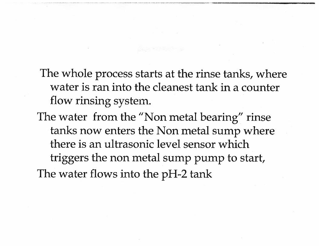
Source Processes and Rinses – There have been recent changes to the source chemistry and rinse management methods. The anodizing tank line capacity has been nearly tripled. A flowing double countercurrent rinse tank follows a spray rinse and prior chemical process tanks. They are fed industrial water (potable water after backflow prevention) or deionized water. The water is metered into each rinse tank by flow control valves on 0 to 5 gallons per minute (gpm) rotameters. There is a master on/off valve for each of the tank lines. Though currently within reasonable rinsing flow rates, it is not required or recommended the rotameters be changed out to 0 to 1 gpm range and their flow tuned to the desired, final rinse quality. The rinse water volume and chemistry will be within a reasonable range of use.
Proposed Waste Water Treatment - Metal and non-metal bearing rinse tanks are segregated and directed to their separate transfer tanks. The non-metal bearing rinse water is directed to a final pH control system. The metal bearing rinse water is directed to a metal bearing rinse holding tank via tank line local transfer tanks. The metal bearing waste water in the holding tank is subject to one of two treatment alternatives. Traditional chemical/physical precipitation is a backup procedure. The second, preferred procedure is continuous flowing pH adjustment followed by a pump, filtration, and metal selective ion exchange.
Compliant precipitation or ion exchange treated water would be discharged to the final pH control system (i.e., pH control system receives all Categorical wastewater).

Engineering Report, Production Plating, Inc. Page 2-5 w:\2018\1896032.00_productionplating_er\2019_eng_rpt\_production plating er v2.wp.docx
Figure 1, Site Plan, and Figure 2, Existing Wastewater Treatment Layout, show the scaled plan view location of the four types of treatment systems, their wastewater sources, and the route for conveyance of treated wastewater to the public sanitary sewer.
As a backup method, an existing batch treatment system would be used to collect and perform chemical/physical treatment on metal bearing rinse water, floor wash water, and maintenance solutions (the latter two streams should be screened, and jar tested prior to batch treatment). The batch tanks are plastic, conical bottom tanks. Some are fitted with a mixer, bottom sludge drain, and side decant connections. With wastewater in the batch treatment tank, the precipitation sequence is to stir the contents, sample/jar test, pH adjust with sodium or calcium hydroxide, add a precipitant if needed, and add a coagulant followed by a flocculent to cause the formed solids to enlarge, quickly settle out, and produce clarified water. The batch treatment system will consist of: (1) 84-inch diameter ~ 1,500-gallon conical bottom tank used for batch treatment (1) 90-inch diameter ~ 3,000-gallon conical bottom tank used for sludge thickener (1) 60-inch diameter ~ 1,500-gallon conical bottom tank used for sludge thickener (1) 96-inch diameter ~ 1,250-gallon conical bottom tank used for pH adjustment (2) 64-inch diameter ~ 1,500-gallon conical bottom tank used for storage
Upon completion of the chemical additions, the mixer is turned off and the formed solids are allowed to settle. The treated water is analyzed onsite with an atomic adsorption instrument (a color comparator for metal is suggested for quick, real-time feedback) to determine compliance with the discharge permit. Upon a compliant reading, the treated water is decanted off the top of the solids via tank side wall drain valves to the final pH control system. Alternatively, if the treated water’s metal concentration is too high, the water can be re-treated to a beaker scale determined method. The pH adjustment and metal ion exchange method would use the same metal analysis methods and the metal treated water directed to the final pH control system.
The settled sludge in the batch tank, if any, is drained to a sludge settling tank. The liquid from the top of the settling tank is directed back to a batch treatment tank. The settled sludge is a secondary waste stream that is separately collected, filter pressed, dried, and packaged for shipment offsite to a Resource Conservation and Recovery Act (RCRA) licensed hazardous waste Treatment, Storage, and Disposal Facility (TSDF).
The part type and their quantity per unit production time do not significantly vary. Therefore, like repetitive production shops, the rinse tank flow rates can be proportionally set to a specified production rate. That is, the tank line’s rinse tank flow is to be turned on/off by the system operator during production. That is the current practice and will continue after the pretreatment upgrades. PPI is encouraged to use handheld conductivity measurements of the final rinse tank (i.e., referenced to conductivity readings of known process chemistry dilutions concentrations) to set the rinse tank flow rate to a practical minimum.
(h) All necessary maps and layout sketches;
See attached Figure 2 for the existing system and Appendix B for the new system.

Engineering Report, Production Plating, Inc. Page 2-6 w:\2018\1896032.00_productionplating_er\2019_eng_rpt\_production plating er v2.wp.docx
(i) Provisions for bypass, if any;
There are no provisions for by-passing or intention to by-pass any of the treatment systems.
(j) Physical provision for oil and hazardous material spill control or accidental discharge prevention or both;
The wastewater treatment area and the metal finishing tanks are contained in areas with concrete berms to contain spills. Solid chemicals can be located outside the spill containment area but within the building since they have no reasonable method of release to the environment. All other hazardous materials are stored within enclosed areas on containment pallets. There are no floor drains within the containment areas.
(k) Results to be expected from the treatment process including the predicted wastewater characteristics, as shown in the waste discharge permit, where applicable;
The existing treatment system has met discharge limits in their permit with the City, with few minor exceptions for copper and zinc.
Table 2.3: Discharge Limits Effluent Limits
Latitude: 47.894 degrees North Longitude: 122.293 degrees West
Parameter Sample Point
Number Monthly Average Maximum Daily Flow (gpd) 001 N/A 50,000 Cadmium, T (mg/L) 001 0.07 0.11 Chromium, T (mg/L) 001 1.71 2.77 Copper, T (mg/L) 001 2.07 3.38 Lead, T (mg/L) 001 0.43 0.69 Nickel, T (mg/L) 001 2.38 3.98 Silver, T (mg/L) 001 0.24 0.43 Zinc, T (mg/L) 001 1.48 2.61 Total Toxic Organic Compounds (TTO) 40 CFR Part 433 (mg/L)
001 N/A 2.13
Cyanide,T (mg/L) 002 0.65 0.86 Parameter Minimum Maximum
pH (standard pH units) 001 6.0 10.0
The new treatment system will use ion exchange instead of chemical precipitation and should reduce or eliminate any exceedances in the future.
(l) A description of the receiving water, location of the point of discharge, applicable water quality standards, and how water quality standards will be met outside of any applicable dilution zone;
The facility's pretreatment system discharges to a sanitary sewer that flows to the Mukilteo Water and Wastewater District’s Big Gulch Wastewater Treatment Plant that discharges to Puget Sound and is subject to an NPDES permit.

Engineering Report, Production Plating, Inc. Page 2-7 w:\2018\1896032.00_productionplating_er\2019_eng_rpt\_production plating er v2.wp.docx
(m) Detailed outfall analysis;
Not applicable to this project.
(n) The relationship to existing treatment facilities, if any;
Improvements will be integrated into the existing treatment facilities.
(o) Where discharge is to a municipal sewerage system, a discussion of that system's ability to transport and treat the proposed industrial waste discharge without exceeding the municipality's allocated industrial capacity. Also, a discussion on the effects of the proposed industrial discharge on the use or disposal of municipal sludge;
The facility’s pretreatment system’s discharge to the POTW (City of Mukilteo Big Gulch Treatment Plant) will be insignificant. The proposed discharge will not significantly increase the flow, or the type or concentration of pollutants to the POTW. The Big Gulch treatment plant’s biosolids report shows metal concentrations well below legal limits while accepting wastewater from PPI using their current treatment system. See Appendix C for recent reports.
The proposed project will retain the existing volume discharge limit but significantly decrease its pollutant contribution for subject metals. For example, the existing permit’s monthly average metal concentrations are near their respective metal ion plus metal hydroxide solubility limits. The proposed ion exchange system’s discharge total metal concentrations will be, at most, one tenth and more typically, one hundredth the metal/metal hydroxide solubility concentrations. Therefore, hydraulic impacts remain the same, but the pollutant concentration impacts are significantly less (i.e., lower impacts, not higher).
(p) Where discharge is through land application, including seepage lagoons, irrigation, and subsurface disposal, a geohydrologic evaluation of factors such as:
(i) Depth to ground water and ground water movement during different times of the year;
Not applicable.
(ii) Water balance analysis of the proposed discharge area;
Not applicable.
(iii) Overall effects of the proposed facility upon the ground water in conjunction with any other land application facilities that may be present;
Not applicable.

Engineering Report, Production Plating, Inc. Page 2-8 w:\2018\1896032.00_productionplating_er\2019_eng_rpt\_production plating er v2.wp.docx
(q) A statement expressing sound engineering justification through the use of pilot plant data, results from other similar installations, or scientific evidence from the literature, or both, that the effluent from the proposed facility will meet applicable permit effluent limitations or pretreatment standards or both;
The existing unit processes, chemistry (i.e., filtration, pH adjustment, precipitation, solids coagulation, flocculation, sedimentation, ion exchange) and treatment methods are well established and relatively unsophisticated technologies that are practiced in literally hundreds of metal finishing shops’, other industries, and municipal water treatment systems around the country. Given the well-founded state of the art in heavy metal treatment, aqueous solids formation/separation systems, records on similar systems, and experience with many similar systems, no pilot work was needed or performed.
Details of the new treatment procedure’s implementation can be found in almost any trade, regulatory, or academic reference on metal finishing rinse/process water and wastewater treatment. As examples of fundamental treatment hardware and aqueous solids separation treatment, the reader is referred to the following:
"Chemical Engineers’ Handbook", McGraw-Hill, 5th Ed., 1973, pgs. 19-44 through 19-57.
"The NALCO Water Handbook", Nalco Chemical Company, McGraw-Hill, 1979, pgs. 8-1 through 9-50, 11-1 through 11-13.
Purolite Chelation Resin Brochure, http://www.purolite.com/Customized/CustomizedControls/PuroliteProductsManagement/Resources/rid_469.pdf.
Various U.S. Environmental Protection Agency (EPA) guidance and technology review documents.
Kennedy Jenks has designed and installed similar systems for several aerospace companies with processes identical or similar to the existing processes used by PPI.
(r) A discussion of the method of final sludge disposal selected and any alternatives considered with reasons for rejection;
The batch treatment sludge is only generated during the precipitation mode. When it is used, the sludge is a listed waste (i.e., designated F006) to the Dangerous Waste Regulations (WAC 173-303). Sludge was not analyzed for the characteristics contained in that regulation because it is a listed waste. Sludge from other typical systems and a review of the source inputs to the treatment systems indicate the sludge is a very likely candidate for reclamation/recycle. The sludge can be disposed at a licensed TSDF but could be sent to a properly approved sludge reclamation and/or recycle facility.
When the metal ion exchange mode is used, very little, if any, sludge is generated. The metal becomes recyclable solid sheet or sponge that is not hazardous waste defined sludge and, therefore, exempt from the Dangerous Waste Regulations.

Engineering Report, Production Plating, Inc. Page 2-9 w:\2018\1896032.00_productionplating_er\2019_eng_rpt\_production plating er v2.wp.docx
(s) A statement regarding who will own, operate, and maintain the system after construction;
PPI will continue to own, operate, and maintain the treatment systems.
(t) A statement regarding compliance with any state or local water quality management plan or any plan adopted under the Federal Water Pollution Control Act as amended;
The existing facility has had an occasional excursion from zinc and copper limits. The upgraded facility will be capable of operating in compliance with current industrial pretreatment permit requirements. The new ion exchange system has the capability to remove metal ions to a lower level than the traditional chemical precipitation that is currently used.
(u) Provisions for any committed future plans;
PPI has expressed to Ecology an interest in future addition of rinse water recycle hardware. It would be prioritized first to anodize processing lines. See overall treatment system upgrade process and instrumentation diagram (P&ID) for this phased approach as described Section 3 of this report.
(v) A discussion of the various alternatives evaluated, if any, and reasons they are unacceptable;
No alternatives have been considered.
(w) Timetable for final design and construction;
Final engineering design and equipment procurement for Phase 1 will be completed 10 weeks after the approval of this Report. Installation and startup of Phase 1 will be completed 3 weeks after equipment procurement.
Subsequent phases will be completed as capital and engineering is available.
(x) A statement regarding compliance with the State Environmental Policy Act (SEPA) and the National Environmental Policy Act (NEPA), if applicable;
The facility is in an area zoned Light Industrial and is adjacent to land either zoned Light Industrial or Industrial Park by the City.
There is no facility work requiring a building permit for this proposed level of a construction project. This project involves a pre-existing, fully operating metal finishing facility. There are minor facility and component upgrades within this existing facility. There will be no substantive changes in facility use, expansion, or additions. Therefore, this project does not need a SEPA checklist and review by the City planning department. This project does not involve any substantive land or facility planning issues. There are no known NEPA or SEPA actions or need for them.

Engineering Report, Production Plating, Inc. Page 2-10 w:\2018\1896032.00_productionplating_er\2019_eng_rpt\_production plating er v2.wp.docx
(y) Additional items to be included in an engineering report for a solid waste leachate treatment system are:
(i) A vicinity map and also a site map that shows topography, location of utilities, and location of the leachate collection network, treatment systems, and disposal;
Not applicable. A solid waste leachate treatment system is not used.
(ii) Discussion of the solid waste site, working areas, soil profile, rainfall data, and ground water movement and usage;
Not applicable.
(iii) A statement of the capital costs and the annual operation and maintenance costs;
Not applicable.
(iv) A description of all sources of water supply within two thousand feet of the proposed disposal site. Particular attention should be given to showing impact on usable or potentially usable aquifers.
Not applicable.

Engineering Report, Production Plating, Inc. Page 3-1 w:\2018\1896032.00_productionplating_er\2019_eng_rpt\_production plating er v2.wp.docx
Section 3: Selective Metal Ion Exchange
3.1 Introduction PPI currently operates a traditional hydroxide precipitation system with clarification and a sludge press for solids removal. Non-metal bearing rinse waters are pH adjusted and sent directly to the sanitary sewer. PPI proposes to do a three-phase upgrade of their wastewater system. The first phase upgrade is to provide added pretreatment capacity and metal/non-metal segregation as needed to accommodate additional capacity for anodize, chromate conversion, and their support process. Advanced Chemical Technologies, Inc., (ACT), has proposed a second phase ion exchange-based treatment system that will reduce sludge volumes and promote recycling of rinse waters at PPI. PPI needs a stamped engineering report in the format of WAC 173-240-110(5) to communicate the proposed changes to Ecology and the City for revising the existing pretreatment permit.
The primary findings of this Report include the following:
1. The treated wastewater quality can have a very high permit compliance rate.
2. The selected treatment technologies will consistently achieve a chromium discharge concentration well below the discharge permit limits.
3. The pretreatment system will have negligible impact on the County’s POTW.
4. PPI will follow a reasonable, informal pollution prevention planning process as it has during the equipment design phase.
5. The facility will have excellent features to prevent slug discharges to the effluent.
6. The pretreatment means are not particularly complex.
Please refer to Appendix B for the P&ID that shows the proposed upgrade to the wastewater treatment system.
3.2 Phase I Description The first phase is to complete the connection of the last few non-metal bearing rinse sources to the effluent pH control system. This work has some marginal pollution prevention attributes but primarily lowers the capital cost and footprint of Phase 2 systems. Improvements to the pH adjustment system will be made in the first phase of the project.
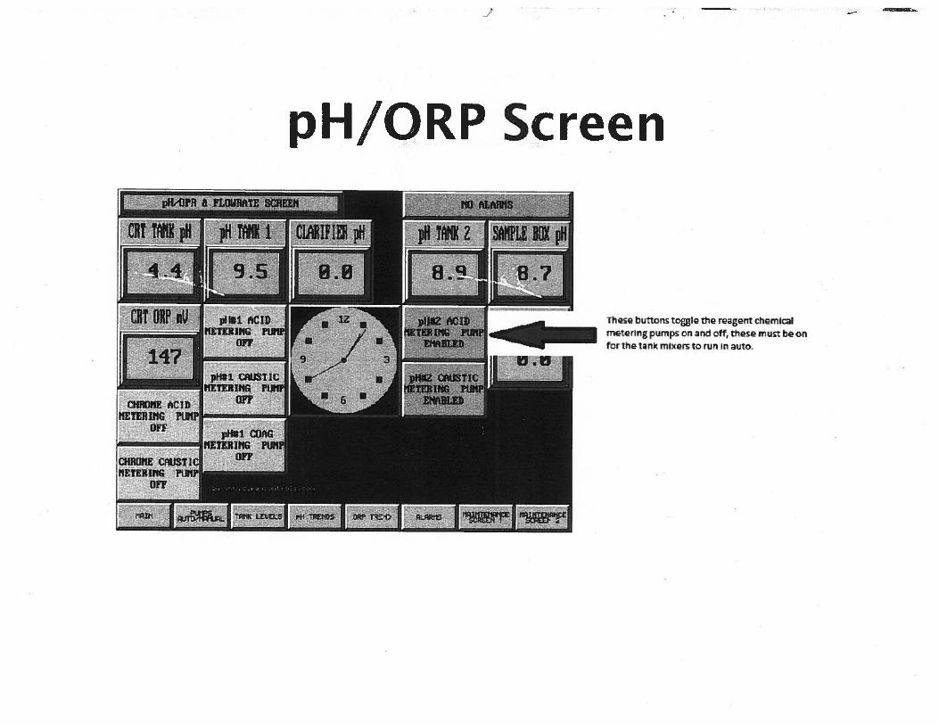
As indicated on the P&ID (Appendix B), there are two wastewater inputs to two pH control systems. The metal bearing rinse water flows to a pH control system with proportional and integral pH control prior to metal selective ion exchange. Wastewater from the non-metal bearing rinse tank transfer stations, the batch treatment tanks after precipitation, or the metal ion exchange system are independently directed to the final pH control system. Treatment chemicals (caustic and acid) are automatically added to the stirred tank contents via a metering pump and a proportional pH controller. The pH-adjusted wastewater gravity drains to the sanitary sewer through a sample site and shut off valve.

Engineering Report, Production Plating, Inc. Page 3-2 w:\2018\1896032.00_productionplating_er\2019_eng_rpt\_production plating er v2.wp.docx
3.3 Phase 2 Description Phase 2 involves installing a metal selective ion exchange system. The system would selectively remove zinc and copper (when high percentage of castings production) from other cations and then chromate from other anions. The metal rich regenerant would be recycled offsite or become an electrowinned metal “sponge” onsite prior to offsite recycling. The advantages are:
A 90 to 95 percent reduction in hydroxide sludge production.
A 90 to 95 percent reduction in treatment chemicals (e.g., acid, caustic, sulfite/sulfide proprietary chemistry, flocculent and coagulants).
A corresponding 90 to 95 percent reduction in sludge drying energy costs and carbon dioxide (CO2) emissions.
Heavy metal discharge concentrations to the POTW are 10 to 100 times lower than typically achieved by metal hydroxide precipitation.
3.4 Phase 3 Description With ion exchange experience gained from Phase 2 and results from other, similar facilities, Phase 3 involves installing a partial to full rinse water recycle system. Anodize process rinses would be prioritized first. As indicated on the flow diagram (Appendix B), it would consist of a batch chemical/physical system feeding a deionizing ion exchange system. The advantages are:
A 30 to 90 percent reduction in water consumption and sewer discharge.
The return of near deionized water allows for spraying off parts withdrawn from ambient and low temperature process tanks without contaminating them.
At least 60 percent of chemical drag out goes back to the source instead of out to waste or sewer discharge.
The hydraulic sizing of rinse flows and subsequent treatment equipment is proportionately reduced.
3.5 Ion Exchange System
3.5.1 Resin Performance and Column Regeneration Frequency The capacity of ion exchange resins is derived from the functional group on the polystyrene matrix. The metal selective resin has an iminodiacetate functional group. It mimics the chemistry of a common chelation chemical – EDTA or ethylene di-tetra-acetic acid. Consequently, metal selective ion exchange resins are also known as “chelation resins.” Metal ions on the periodic table in copper’s column and each side of it are very tightly associated with the resin compared to other cations. Consequently, there is virtually no applicable heavy metal left in the resin’s interstitial water. Past applications and the resin literature indicate the effluent metal concentration will be near AA detection limits [i.e., <50 parts per billion (ppb)].

Engineering Report, Production Plating, Inc. Page 3-3 w:\2018\1896032.00_productionplating_er\2019_eng_rpt\_production plating er v2.wp.docx
The nominal total capacity of an iminodiacetate resin is about 2.9 equivalents per liter (eq/L). It is assumed the resin has been previously regenerated. Therefore, its capacity will be less than the new, maximum capacity. Typically, the resin can be efficiently regenerated to about 75 percent of the new condition. Therefore, a reasonable working capacity is about 2.2 eq/L. Each 12-inch-diameter column with a 4-foot bed depth contains 3.0 cubic feet or 85 liters. Therefore, using the conservatively lowest capacity, one column has 187 equivalents of metal capacity.
It has been previously shown that the maximum metal concentration is 200 mg/L (typically less than 50 mg/L). A concentration of 200 mg/L of metal in the zinc form (i.e., Zn+2) is equal to 6.3 x 10⁻³ eq/L. Therefore, one column can process 29,700 liters or 7,800 gallons of waste water. At the maximum daily volume of maximum metal bearing rinse water (7,500 gallons), it would take about 1 operating day to exhaust one column or nearly a week at the typical metal concentration of less than 50 mg/L. Note that the lead/lag use of two columns allows regeneration of one column (about a 2-hour procedure) while processing with the other column.
The weak anion resin for removing chromate has similar capacity and lower metal concentration that the metal selective resin. Given the columns are the same size, then the run time or regeneration frequency is more favorable than for the metal selective resin.
3.5.2 Process Controls Two resin columns are operated in series. They are operated in a lead-lag fashion (aka, “merry-go-round). The lead column removes virtually all of the metal and zinc or nickel. The second column operates as 1) a safety to catch the first column’s leakage, and 2) catch the very small amount of leakage from the first column as it fully loads up.
The columns are solid polyvinyl chloride (PVC) pipe with 6-inch-diameter viewports at the top, bottom, and middle of the column side wall. The resin will turn color from cream to the metal’s color as it loads with the metal. The color change will progress down the column until the top of the lag column begins to turn color. When the lead column is fully loaded with metal, it is taken offline to regenerate the resin. The lag column can continue operating. Once the lead column has been regenerated, it is placed online as the lag polishing column.
An array of valves and flow controls manage the processing rate and the regeneration sequence. See Appendix B for Ion Exchange Column/Controls.
3.5.3 System and Resin Hydraulics System Operation - It has been previously determined that the maximum metal bearing rinse water flow is 7,500 gpd. Typically, the first shift is the most productive and usually selected to perform the wastewater treatment. Therefore, assume that the maximum daily volume (7,500 gallons) is treated during first shift. That equates to an average flow rate through the pH control, ion exchange system, and to the final pH control system of 15 gpm.
Note the lag column can process wastewater while the lead column is being regenerated (i.e., no total system down time). The final pump maximum pressure is subject to final design. It is preliminarily set at 50 pounds per square inch (psi) to account for two loaded filters at 7 psi each, 3 psi across each column, piping flow losses, and a delivery pressure of at least 5 psi.

Engineering Report, Production Plating, Inc. Page 3-4 w:\2018\1896032.00_productionplating_er\2019_eng_rpt\_production plating er v2.wp.docx
Resin Hydraulics - The effectiveness of ion exchange reactions is dependent on many factors. A few of the interdependent factors are temperature, superficial flow rate, residence time, ionic concentration, competing ions, ion molecular weight, and ion valence. Resin vendor data, rules-of-thumb, and experience can be applied in the absence of quantitative methods. Turbulent flow through the resin bed is avoided by staying below 50 gpm per square feet (sq. ft.). High pressure drop and poor reaction kinetics (much less concern with chelation resins) are avoided by staying below 20 gpm/sq. ft. Pump and pipe systems are designed for the higher pressure drop experienced at low temperature.
The columns are nominal 12-inch diameter and contain 3 cubic feet of resin. Their inside diameter is about 11.5 inches with a corresponding cross-sectional area of 0.72 sq. ft. The maximum service flow rate of 15 gpm corresponds to 20 gpm/sq. ft. This specific flow rate is at the rule-of-thumb limit. The resin bed depth is about 4.0 feet which is 2.0 feet above resin manufacturer’s recommended minimum.
Filtration Requirements - The hydraulics and corresponding capacity of ion exchange resins partially depend on adequate pre-filtration. Suspended solids accumulating in a resin bed can cause preferential flow paths that can short circuit portions of the resin bed. Accumulation of fine material on the resin bead surface can hinder ion diffusion to the exchange site. The industry standard filtration ahead of frequently loaded resins (i.e., metal selective resins) is 20 microns. This engineer finds that resin beds subject to long run times) between change out require 5-micron filtration or better. In this application, operations can start out with dual filters at 50 and 20 microns. If operating experience warrants it, the lag filter’s micron rating can be lowered to extend operating runs.
The cartridge filter systems that precede the ion exchange canisters are sized to provide the maximum flow rate of 15 gpm at a maximum pressure drop of 1 psi when the filters are clean. The pump’s hydraulic curve is selected to peak at less than 15 psi greater than the maximum system pressure drop (pressure relief valve set in this range). The filter’s maximum dirty pressure drop is 5 to 7 psi depending on the selected filter type.

Figures

WSW SW SW SW SW SW SW
SWSW
SWSW
SWSW
SWSW
SW
SS
SS
SS
SS
SS
SW
SW
SW
SS
W
WW
WW
W
SS
SS SS
WW
RUSSELL ROAD
CYR
US
RO
AD
LOT 41
LOT 40
4412
4416
W
SS
Kennedy/Jenks Consultants
PRODUCTION PLATINGMUKILTEO, WASHINGTON
SITE PLAN
1896032_FIG-01
FIGURE 1
0
1"=30'
20 40 60SITE PLAN

WSW SW SW SW SW SW SW
SWSW
SWSW
SWSW
SWSW
SW
SS
SS
SS
SS
SS
SW
SW
SW
SS
W
WW
WW
W
SS
SS SS
WW
RUSSELL ROAD
CYR
US
RO
AD
LOT 41
LOT 40
4412
4416
W
SS
1 2
3
4
5
6
9
8
7
11
10
14
13
12
17
15 16
Kennedy/Jenks Consultants
PRODUCTION PLATINGMUKILTEO, WASHINGTON
EXISTING WASTEWATER
TREATMENT LAYOUT
1896032_FIG-02
FIGURE 2
0
1"=30'
20 40 60SITE PLAN
LEGEND:
DYNA SAND FILTER
CLARIFIER
SLUDGE THICKENER TANK
CONVEYER
C.B. TANK
FILTER PRESS
CHROME REDUCTION TANK
1
2
3
4
5
6
7
PH ADJUST
LIFT TANK
SLUDGE THICKENER TANK
SODIUM HYPOCHLORITETANK
STORAGE TANK
NITRIC ACID TANK
NITRIC ACID TANK
8
9
10
11
12
13
14
SLUDGE SETTLING TANK
BATCH PROCESS TANK
PH2 TANK
15
16
17

Appendix A
Treatment System Operations Manual


Appendix B
Treatment System Drawings

PI PI PI
PI
AIR
SLUDGETHICKENER
TANK
2"
1"
LS
LE123
HOA
HS123
LT123
25% CAUSTIC25% ACID
A123
pH
HQ123
HS123
HOA
HQ123
HS123
HOA
AIC4
C1
HZ123
HS123
HQ123
XX
XX
XX
XX
XX
CHECK VALVE
FLOW RATE CONTROL VALVE
SOLENOID VALVE
GLOBE VALVE
RELIEF OR REGULATING VALVE
INSTRUMENT INTEGRAL WITHASSOCIATED EQUIPMENT,FIELD MOUNTED
INSTRUMENT IS PANEL FRONTMOUNTED ON ASSOCIATEDEQUIPMENT
INSTRUMENT INSTALLED ONTHE EQUIPMENT/PIPING,FIELD MOUNTED
INSTRUMENTS BOTHINTEGRAL WITH ASSOCIATEDEQUIPMENT, PANEL MOUNT
FIRST VARIABLE
A ANALYSIS/ANALYTIC
F FLOW
H HAND
S SWITCH
T TEMPERATURE
P PRESSURE
SECOND VARIABLE
C CONTROLLER
I INDICATOR, INDICATION
E SENSING ELEMENT
Q FREQUENCY OR TOTALIZER
Z LENGTH
THIRD VARIABLE
SAME AS SECOND ORMODIFIES SECOND VARIABLE
H HIGH
L LOW
HH VERY HIGH
LL VERY LOW
T TRANSMITTER
EXAMPLES
HS HAND SWITCH
AIC ANALYSIS (I.E., ORP OR pH) WITH INDICATOR AND CONTROLLOOP
HZ METERING PUMP HAND CHANGE OF STROKE LENGTH
HK METERING PUMP HAND CHANGE OF STROKE RATE
AE ANALYSIS (I.E., ORP OR pH) SENSOR
FEIQ FLOW METER WITH FLOW INDICATION AND TOTALIZER
TIC TEMPERATURE INDICATING CONTROLLER
HOA HAND, OFF, AUTO SWITCH TYPE
HQ METERING PUMP HAND CHANGE OF STROKE RATE
BALL OR GATE VALVE,NORMALLY OPEN
BALL OR GATE VALVE,NORMALLY CLOSED
FLOW
SAMPLE VALVE, LABCOCK
BACK PRESSURE REG. VALVE
XXFIELD MOUNTED INSTRUMENT,EQUIPMENT OR PROCESSNUMBER
FLOW
FLOW
PI
IN LINE WYE STRAINER WITH VALVED BLOWDOWN
MALE QUICK DISCONNECT HOSE CONNECTION
PIPE TO HOSE BARB FITTING
PRESSURE INDICATOR W/LIQUID ISOLATION
SELF CONTAINED TAP
SELF CONTAINED TAP
NORMALLY OPEN
CP5A 400 DWG. NO. AND CONNECTION NO.
XX INSTRUMENT IS MOUNTEDBEHIND PANEL FRONT ONASSOCIATED EQUIPMENT
I INTERLOCK
LS
AT123
pH
HS123
HS123
4% SULFURIC ACID
6% SODIUMHYDROXIDE
FI
PI
HE
X C
HR
OM
IUM
CO
LUM
N
FI
FI
SETTLED SLUDGE
POLYMER TANKTRANSFER TANK PRESSED SLUDGETO DRYER
POLYMER
FILT
ER
20u
FILT
ER
50u
ME
TAL
SE
LEC
TIV
E C
OLU
MN
FI
PI
FI
FI
HZ123
HZ123
LIC4
C1
AIR
LS
HEX CHROMIUMWASTE WATER
LS
Zn, Cu, Ni, Cr3WASTE WATER
HE
X C
HR
OM
IUM
CO
LUM
N
ME
TAL
SE
LEC
TIV
E C
OLU
MN
WASTECHEMICAL
USEDCHEMICAL
USEDCHEMICAL
15% CAUSTIC
A123
pHQ
123HZ123
HS123
HOA
AIC3
C1
HQ123
10% ACID
Q123
HZ123
HS123
HOA
HQ123
EFFLUENT pHCONTROL TANK
SANITARYSEWER
WASTE WATERSURGE TANK
2000 GAL.
WATER
HS123
HS123
Q123
Q123
TRANSFERTANK
TRANSFERTANK
PI
WASTE CHEMICAL TO PLATE OUTCELL OR BATCH TREATMENT OR OFF
SITE METALS RECYCLE
MANUAL ADDITION OFPOLYMER AND PRECIPITATION
AIDES AS NEEDED
WATER
RETURN OF ION EXCHANGE COLUMNBACKWASH AND RINSE WATER
NON-METALWASTE WATER
LS
NON-METALALKALINE
WASTE WATER
LS
NON-METALACIDIC WASTE
WATER
TRANSFERTANK
TRANSFERTANK
PI PI PI
PI
PI
LE123
HOA
HS123
LT123
A123
pH
4% SULFURIC ACID
6% SODIUMHYDROXIDE
FI
PI
FI
FI
FILT
ER
5u
OR
CA
RB
ON
FILT
ER
20u
FILT
ER
50uCA
TIO
N IO
N E
XC
HA
NG
E C
OLU
MN
FI
PI
FI
FI
LIC4
C1
USEDCHEMICAL
USEDCHEMICAL
SURGE/FEEDTANK
PI
WATER
RETURN OF ION EXCHANGE COLUMNBACKWASH AND RINSE WATER
WATER RECYCLE
CA
TIO
N IO
N E
XC
HA
NG
E C
OLU
MN
AN
ION
ION
EX
CH
AN
GE
CO
LUM
N
AN
ION
ION
EX
CH
AN
GE
CO
LUM
N
A123
pH
AIC3
10% ACID
Q123
HZ123
HS123
HOA
HQ123
METAL IX pHCONTROL TANK
200 GAL.
FE123
FI123
C1
PHASE 1
PHASE 2
PHASE 2
PHASE 3
PHASE 2
PHASE 3
PHASE 2
PHASE 3
PHASE 3
Email:
allan
_adv_c
hem@m
sn.com
Fax (4
25) 86
8-588
2Tel
(425)
868-7
804Red
mond,
WA 98
073
ACT JOB No
ADVA
NCED
CHE
MICA
LP.O
. Box
21
TECH
NOLO
GIES
, INC.
CHEM
ICAL
ENG
INEER
S
DESIGNED
DRAWN
REVISIONS/DATE
CHECKED
DATE
PROD
. PLAT
E - P
1
PROC
ESS
META
L & R
ECYC
LE ION
EXC
HANG
E UP
GRAD
EPR
ODUC
TION
PLATING
, INC.
FACILTIY ION
EXC
HANG
E UP
GRAD
ES
P1PROD. PLATE
G.A.
07/1
7/19
G.A.
G.A.
SCOPE OF WORK BOUNDARYEXCEPT COLUMNS, FLANGES,
CHEMICALS & INTERCONNECTINGPIPE/FITTINGS BETWEEN MAJOR
SKIDS/ASSEMBIES.

Email:
allan
_adv_c
hem@m
sn.com
Fax (4
25) 86
8-588
2Tel
(425)
868-7
804Red
mond,
WA 98
073
ACT JOB No
ADVA
NCED
CHE
MICA
LP.O
. Box
21
TECH
NOLO
GIES
, INC.
CHEM
ICAL ENG
INEER
S
DESIGNED
DRAWN
REVISIONS/DATE
CHECKED
DATE
PROD
. PLAT
E - P
1
PROC
ESS
PRETRE
ATME
NT U
PGRA
DEPR
ODUC
TION
PLATING
, INC.
ION
EXCH
ANGE
CON
FIGU
RATION
P2PROD. PLATE
G.A.
07/17/
19
G.A.
G.A.
7'-11"8'
10"
9"
8"
12 GPM@ 50 PSI
APPROX.GALLONS
CONTROLPANEL
SERFILCO PL30(1)S-1-G3,78-1132, TYP. 2 OR EQUAL
1.5 GPM @ 7PSI, TYP. 2
METAL IX PLANSCALE: 1" = 1'-0" 1
IX COLUMN/PIPING ASSEMBLYSCALE: NTS 3
METAL IX ELEVATIONSCALE: 1" = 1'-0" 2
NOTES:
7'-5"
3'-6"
SUGGESTED LAYOUT FOR FINAL DESIGN BY FABRICATOR.SEE NOTES FOR PERFORMANCE DETAILS.
SUGGESTED LAYOUT FOR FINAL DESIGN BY FABRICATOR.SEE NOTES FOR PERFORMANCE DETAILS.
3'-5"
1. SEE PIPING & INSTRUMENTATION DIAGRAM (P&ID) FOR FULL SCOPE OF COMPONENTS TO BE INCLUDED IN THESE SUGGESTED ASSEMBLY'S CONFIGURATION.2. FINAL PUMP, FILTER AND TANK SKID LAYOUT AND ELEVATION IS TO FABRICATOR'S FINAL CONFIGURATION SUBJECT OWNER APPROVAL PRIOR TO FABRICATION.3. MINIMIZE COLUMN FACE PIPING ASSEMBLY WIDTH. INSTALLER TO PLACE COLUMNS' VERTICAL CENTER LINE WITH PIPING OUTSIDE VERTICAL HEADERS.4. USED COLUMNS SUPPLIED TO FABRICATOR BY OWNER FOR FABRICATOR'S REMOVAL/REPLACE (W/304 SS) RUSTED TIGHT FLANGE BOLTS AND GASKETS (I.E., 8 SETS).5. OWNER'S COLUMNS INCLUDE THE FRP WIDE FLANGE SUPPORTS.6. SEE EQUIPMENT PARAMETERS ON DRAWING DETAILS. ALL CALL OUTS ARE ON "OR APPROVED EQUAL" BASIS. CUSTOMER VALUE IS IMPORTANT.7. MATERIALS OF CONSTRUCTION TO BE PVC, FRP, STAINLESS STEEL, VINYL ESTER POWDER COAT, HIGH EPOXY SOLIDS OR APPROVED EQUAL. SURFACE PREP TO COATING TDS.8. PIPE AND FITTINGS TO BE SCH. 80 PVC.9. MATERIAL LIST AND SHOP ASSEMBLY DWGS. SUBMITTED FOR APPROVAL PRIOR TO FABRICATION. SHIP SCHEDULE TO ASSUME 2 BUSINESS DAY APPROVAL TURN AROUND.10. TECHNICAL QUESTIONS TO THIS DWGS. CONTACT INFO. COMMERCIAL PAPER AND QUESTIONS TO SKILLS' JACK HUCHINSON.
PLASTOMATIC RTVRELIEF VAVLE
0-75 PSITYP. 4
CLEARDRAINLINE
SAMPLE VALVETYP. 4
0-5 GPM
0-15 GPM
1/2"
1/2"
1/2"
1-1/4"
1-1/4"
GLOBE VALVETYP. 4
CHEM. IN &SLOW RINSE
FAST RINSE
1/2"
1/2"
1-1/2" FRPSTRUT
40 MESHSTRAINER
0-15 GPMFEEDWATER
0-10 GPMBACKWASH
1"
1"
1/2"
1-1/4"
1/2"
POTABLEWATER, 1"
CHEM. IN,1/2"
1-1/4" WASTEWATER IN
RINSE OUTWATER, 1"
CHEM.OUT, 1/2"
FOUR COLUMNS WITHFLANGES TO BE DELIVEREDBY OWNER TO FABRICATOR
FABRICATOR TO REMOVE RUSTEDOUT FLANGE BOLTS/GASKET
AND REPLACE WITH SS BOLT SETAND NEOPRENE GASKET. EXISTING
BEAM SUPPORT TO BE REPLACEDWITH NEW FRP 4X8 BEAM.
FABRICATOR TO INCLUDE STRUT PIPING FRAMEAS NEEDED TO SUPPORT PIPE/VALVE/FITTING
NETWORK PLUS RIGID ATTACHMENT THEREOFTO COLUMNS AND COLUMN BASE BEAMS.
Appendix C
Big Gulch Treatment Plant Biosolids Reports

Big Gulch Wastewater Treatment Facility Biosolid Data Report 2017
Analyte: Method:Table 1 Limits:
Table 2 Limits:
Table 3 Limits:
First Quarter 3/31/17
Second Quarter 6/30/17
Third Quarter 9/30/17
Fourth Quarter 12/31/17
PollutantsAntimony,ug/g EPA 6010C <3.49 <7.9 29.4Arsenic, ug/g EPA6010C 75 mg/Kg 41 mg/Kg 41 mg/Kg <3.68 <3.49 <7.9 <11.5Beryllium, ug/g EPA 6010C N/A N/A N/A <0.183 N/A <0.789 0.634Cadmium, ug/g EPA 6010C 85 mg/Kg 39 mg/Kg 39 mg/Kg 2.64 1.93 1.545 1.97Chromium,ug/g EPA 6010C N/A N/A N/A 80 61.4 44.1 60.7Copper, ug/g EPA 6010C 4300 mg/Kg 1500 mg/Kg 1500 mg/Kg 250 226 208 269Lead, ug/g EPA 6010C 840 mg/Kg 300 mg/Kg 300 mg/Kg 10.1 13.8 9.2 13.7Mercury,ug/g SW-846 7471A 57 mg/Kg 17 mg/Kg 17 mg/Kg 0.569 0.477 1.48 0.681Molybdenum,ug/g EPA 6010C 75 mg/Kg N/A N/A 11.7 9.54 12.6 11.4Nickel, ug/g EPA 6010C 420 mg/Kg 420 mg/Kg 420 mg/Kg 21.9 19.5 18.9 33Phosphorus, ug/g EPA 6010C N/A N/A N/A 16,200 18,100 14,300 20,600Potassium, ug/g EPA 6010C N/A N/A N/A 4,320 6,940 4,880 4,110Selenium, ug/g EPA 6010C 100 mg/Kg 100 mg/Kg 100 mg/Kg 3.68 1.83 <3.94 9.23Silver, ug/g EPA 6010C N/A N/A N/A <1.83 <1.75 13.7 <5.73Thallium, ug/g EPA 6010C N/A N/A N/A <1.83 <1.75 <3.94 <5.73Zinc, ug/g EPA 6010C 7500 mg/Kg 2800 mg/Kg 2800 mg/Kg 636 558 226 536NutrientsAmmonia, ug/g SM-4500NH3-E 8,080 5,770 7,490 8,730Available Ammonia,mg/Kg Plumb 1981 2,500 2,300 1,500 1,700pH, pH SW-846 9045D 6.1 6.5 5.4 5.3Nitrate + Nitrite,ug/g SM-4500NO3 F 130 <4 <4.1 <3.5TKN,ug/g SM 4500N C 58,000 18,000 54,000 62,000Sulfate,ug/g EPA 300.0W-846 9038 530 19 12 130Organic Nitrogen,ug/g EPA Calc. 49,900 12,200 46,500 53,300Sulfur EPA 6010C 8,960 7,500 7,830 10,200
Bacteriological #1 Fecal Coliform/g SM 9221 235,294 108,333 56,911 307,018#2 Fecal Coliform/g SM 9221 57,377 57,851 77,049 439,024#3 Fecal Coliform/g SM 9221 77,049 40,833 63,710 1,379,310#4 Fecal Coliform/g SM 9221 40,164 137,097 91,667 786,325#5 Fecal Coliform/g SM 9221 40,708 55,118 229,508 41,525#6 Fecal Coliform/g SM 9221 83,186 64,228 321,101 120,690#7 Fecal Coliform/g SM 9221 41,525 84,615 45,794 793,103Geonetric mean, MPN/g <2,000,000 66,702 72,481 97,937 344,942ConventionalsTotal Solids, % SM 2540B 12.5 10.9Initial TVS% SM 2540G 82.4 84.8 84.8 86.6Final TVS% SM 2540G 81.8 79.3 82.6 79.2% Reduction 4 31.3 14.9 41.1Vector Attraction Achieved? VanKleek YES NO YES NO
Appendix C for Engineering Report, Production Plating, Inc.W:\2018\1896032.00_ProductionPlating_ER\2019_Eng_Rpt\Appendix_C\biosolidsreport17.xls

Big Gulch Wastewater Treatment Facility Biosolid Data Report 2018
Analyte: Method:Table 1 Limits:
Table 2 Limits:
Table 3 Limits:
First Quarter 3/31/18
Second Quarter 6/30/18
Third Quarter 9/30/18
Fourth Quarter 12/31/18
PollutantsAntimony,ug/g EPA 6010D <3.28 <0.92 <2.1 <1.64Arsenic, ug/g EPA6010D 75 mg/Kg 41 mg/Kg 41 mg/Kg 3.31 1.72 3.97 4.27Beryllium, ug/g EPA 6010D N/A N/A N/A <0.328 <0.092 <0.21 <0.164Cadmium, ug/g EPA 6010D 85 mg/Kg 39 mg/Kg 39 mg/Kg 1.65 <0.092 1.527 1.259Chromium,ug/g EPA 6010D N/A N/A N/A 32.7 32.5 41.5 49.3Copper, ug/g EPA 6010D 4300 mg/Kg 1500 mg/Kg 1500 mg/Kg 167 75.9 226 269Lead, ug/g EPA 6010D 840 mg/Kg 300 mg/Kg 300 mg/Kg <6.53 3.6 16.4 10.3Mercury,ug/g SW-846 7471B 57 mg/Kg 17 mg/Kg 17 mg/Kg 0.246 0.91 0.397 1.03Molybdenum,ug/g EPA 6010D 75 mg/Kg N/A N/A 7.36 3.93 13.2 15.1Nickel, ug/g EPA 6010D 420 mg/Kg 420 mg/Kg 420 mg/Kg 17 10.5 30.4 33.6Phosphorus, ug/g EPA 6010D N/A N/A N/A 14,900 6,200 13,600 12,700Potassium, ug/g EPA 6010D N/A N/A N/A 3,370 1,560 2,580 2,120Selenium, ug/g EPA 6010D 100 mg/Kg 100 mg/Kg 100 mg/Kg 5.95 1.07 4.81 4.97Silver, ug/g EPA 6010D N/A N/A N/A <3.28 1.31 5.11 2.03Thallium, ug/g EPA 6010D N/A N/A N/A <3.28 <0.92 <2.1 <1.64Zinc, ug/g EPA 6010D 7500 mg/Kg 2800 mg/Kg 2800 mg/Kg 336 151 410 462NutrientsAmmonia, ug/g SM-4500NH3-E 12,900 13,200 2,760 5,920Available Ammonia,mg/Kg Plumb 1981 3,100 4,200 1,900 1,100pH, pH SW-846 9045D 5.6 5.8 6.1 5.1Nitrate + Nitrite,ug/g SM-4500NO3 F 16 110 65 23TKN,ug/g SM 4500N C 79,000 79,000 76,000 62,000Sulfate,ug/g EPA 300.0 200 630 <76 660Organic Nitrogen,ug/g EPA Calc. 66,100 65,800 73,200 56,100Sulfur EPA 6010D 12,100 2,920 7,860 7,970
Bacteriological #1 Fecal Coliform/g SM 9221 1,848,739 195,122 166,667 269,231#2 Fecal Coliform/g SM 9221 699,115 86,614 138,211 94,891#3 Fecal Coliform/g SM 9221 408,333 109,375 112,000 760,331#4 Fecal Coliform/g SM 9221 873,016 103,175 165,414 83,969#5 Fecal Coliform/g SM 9221 1,076,923 133,858 139,344 760,331#6 Fecal Coliform/g SM 9221 1,328,125 166,667 289,256 193,548#7 Fecal Coliform/g SM 9221 385,827 218,750 62,205 269,231Geonetric mean, MPN/g <2,000,000 822,318 137,532 140,299 252,048ConventionalsTotal Solids, % SM 2540BInitial TVS% SM 2540G 85.4Final TVS% SM 2540G 78.9% Reduction 36.1Vector Attraction Achieved? VanKleek NOSOUR EPA1683 apr-1.07 jul-1.34 oct-0.58SOUR EPA1683 may-1.37 aug-1.07 nov-0.74SOUR EPA1683 jun-1.01 sep-1.01 dec-0.49
Appendix C for Engineering Report, Production Plating, Inc .W:\2018\1896032.00_ProductionPlating_ER\2019_Eng_Rpt\Appendix_C\biosolidsreport18.xls

Big Gulch Wastewater Treatment Facility Biosolid Data Report 2019
Analyte: Method:Table 1 Limits:
Table 2 Limits:
Table 3 Limits:
First Quarter 3/31/19
Second Quarter 6/30/19
Third Quarter 9/30/19
Fourth Quarter 12/31/19
Monthly SOUR
RESULTS
PollutantsAntimony,ug/g EPA 6010D 17.3 <3.34 4.5Arsenic, ug/g EPA6010D 75 mg/Kg 41 mg/Kg 41 mg/Kg <3.71 <3.34 <4.42Beryllium, ug/g EPA 6010D N/A N/A N/A <0.371 <0.334 <0.442Cadmium, ug/g EPA 6010D 85 mg/Kg 39 mg/Kg 39 mg/Kg 1.41 2.188 1.982Chromium,ug/g EPA 6010D N/A N/A N/A 41.9 66.7 55.8Copper, ug/g EPA 6010D 4300 mg/Kg 1500 mg/Kg 1500 mg/Kg 270 272 259Lead, ug/g EPA 6010D 840 mg/Kg 300 mg/Kg 300 mg/Kg 38.7 10.9 <8.8Mercury,ug/g SW-846 7471B 57 mg/Kg 17 mg/Kg 17 mg/Kg 0.303 0.288 0.389Molybdenum,ug/g EPA 6010D 75 mg/Kg N/A N/A 8.15 10.6 8.74Nickel, ug/g EPA 6010D 420 mg/Kg 420 mg/Kg 420 mg/Kg 34.1 49.1 65.6Phosphorus, ug/g EPA 6010D N/A N/A N/A 18,800 19,300 15,700Potassium, ug/g EPA 6010D N/A N/A N/A 3,920 6,090 3,810Selenium, ug/g EPA 6010D 100 mg/Kg 100 mg/Kg 100 mg/Kg <3.71 5.94 5.59Silver, ug/g EPA 6010D N/A N/A N/A <3.71 <3.34 <4.42Thallium, ug/g EPA 6010D N/A N/A N/A <3.71 <3.34 <4.42Zinc, ug/g EPA 6010D 7500 mg/Kg 2800 mg/Kg 2800 mg/Kg 551 570 649NutrientsAmmonia, ug/g SM-4500NH3-E 10,200 8,980 9010Available Ammonia,mg/Kg Plumb 1981 3,900 1,500 3200pH, pH SW-846 9045D 5.8 6.2 6.1Nitrate + Nitrite,ug/g SM-4500NO3 F 39 12 32TKN,ug/g SM 4500N C 71,000 74,000 69000Sulfate,ug/g EPA 300.0 490 <78 470Organic Nitrogen,ug/g EPA Calc. 60,800 65,000 60000Sulfur EPA 6010D 10,400 10,400 9730Total Solids SM 2540G 13.5 12.8 11.1
Bacteriological #1 Fecal Coliform/g SM 9221 236,486 244,755 132,653#2 Fecal Coliform/g SM 9221 364,865 400,000 372,340#3 Fecal Coliform/g SM 9221 362,416 259,259 519,231#4 Fecal Coliform/g SM 9221 362,416 167,939 35,659#5 Fecal Coliform/g SM 9221 180,451 747,967 41,176#6 Fecal Coliform/g SM 9221 37,692 461,538 800,000#7 Fecal Coliform/g SM 9221 409,091 167,939 435,484Geonetric mean, MPN/g <2,000,000 227,493 305,283 200,704 #NUM!ConventionalsJAN/SOUR EPA1683 <1.5 mg/g 1.24FEB/SOUR EPA1683 <1.5mg/g 0.65MAR/SOUR EPA1683 <1.5mg/g 1.69APR/SOUR EPA1684 <1.5mg/g 1.16MAY/SOUR EPA1685 <1.5mg/g 1.76JUN/SOUR EPA1686 <1.5mg/g 1.09JUL/SOUR EPA1687 <1.5mg/g 0.76AUG/SOUR EPA1688 <1.5mg/g 1.23SEPT/SOUR EPA1689 <1.5mg/gOCT/SOUR EPA1690 <1.5mg/gNOV/SOUR EPA1691 <1.5mg/gDEC/SOUR EPA1692 <1.5mg/gQuarterly TS% 13.5 12.8 11.1
Appendix C for Engineering Report, Production Plating, Inc.W:\2018\1896032.00_ProductionPlating_ER\2019_Eng_Rpt\Appendix_C\biosolidsreport19.xls