Engineering Metrology and Instrumentation · Engineering Metrology and Instrumentation ....
22
Manufacturing, Engineering & Technology, Fifth Edition, by Serope Kalpakjian and Steven R. Schmid. ISBN 0-13-148965-8. © 2006 Pearson Education, Inc., Upper Saddle River, NJ. All rights reserved. Engineering Metrology and Instrumentation
Transcript of Engineering Metrology and Instrumentation · Engineering Metrology and Instrumentation ....

Manufacturing, Engineering & Technology, Fifth Edition, by Serope Kalpakjian and Steven R. Schmid.
ISBN 0-13-148965-8. © 2006 Pearson Education, Inc., Upper Saddle River, NJ. All rights reserved.
Engineering Metrology and Instrumentation

Manufacturing, Engineering & Technology, Fifth Edition, by Serope Kalpakjian and Steven R. Schmid.
ISBN 0-13-148965-8. © 2006 Pearson Education, Inc., Upper Saddle River, NJ. All rights reserved.
Machine-Tool Slideway
Figure 35.1 Cross-section of a machine-tool slideway. The width, depth. Angles,
and other dimensions all must be produced and measured accurately for the
machine tool to function as expected.

Manufacturing, Engineering & Technology, Fifth Edition, by Serope Kalpakjian and Steven R. Schmid.
ISBN 0-13-148965-8. © 2006 Pearson Education, Inc., Upper Saddle River, NJ. All rights reserved.
Analog and
Digital
Measuring
Devices
Figure 35.2 (a) A vernier (analog) micrometer. (b) A digital micrometer with a range of 0 to
1 in. (0 to 25 mm) and a resolution of 50 μin. (1.25μm). It is generally easier to read
dimensions on this instrument compared to the analog micrometer. (c) Schematic
illustration showing the integration of digital gages with microprocessors for real-time data
acquisition for statistical process control. Source: (a) Courtesy of L.C. Starret Co. and (b)
Courtesy of Mitutoyo Corp.
Manufacturing, Engineering & Technology, Fifth Edition, by Serope Kalpakjian and Steven R. Schmid.
ISBN 0-13-148965-8. © 2006 Pearson Education, Inc., Upper Saddle River, NJ. All rights reserved.
Digital-Micrometer Depth Gage
Figure 35.3 A digital micrometer depth gage.
Source: Courtesy of Starret Co.
Manufacturing, Engineering & Technology, Fifth Edition, by Serope Kalpakjian and Steven R. Schmid.
ISBN 0-13-148965-8. © 2006 Pearson Education, Inc., Upper Saddle River, NJ. All rights reserved.
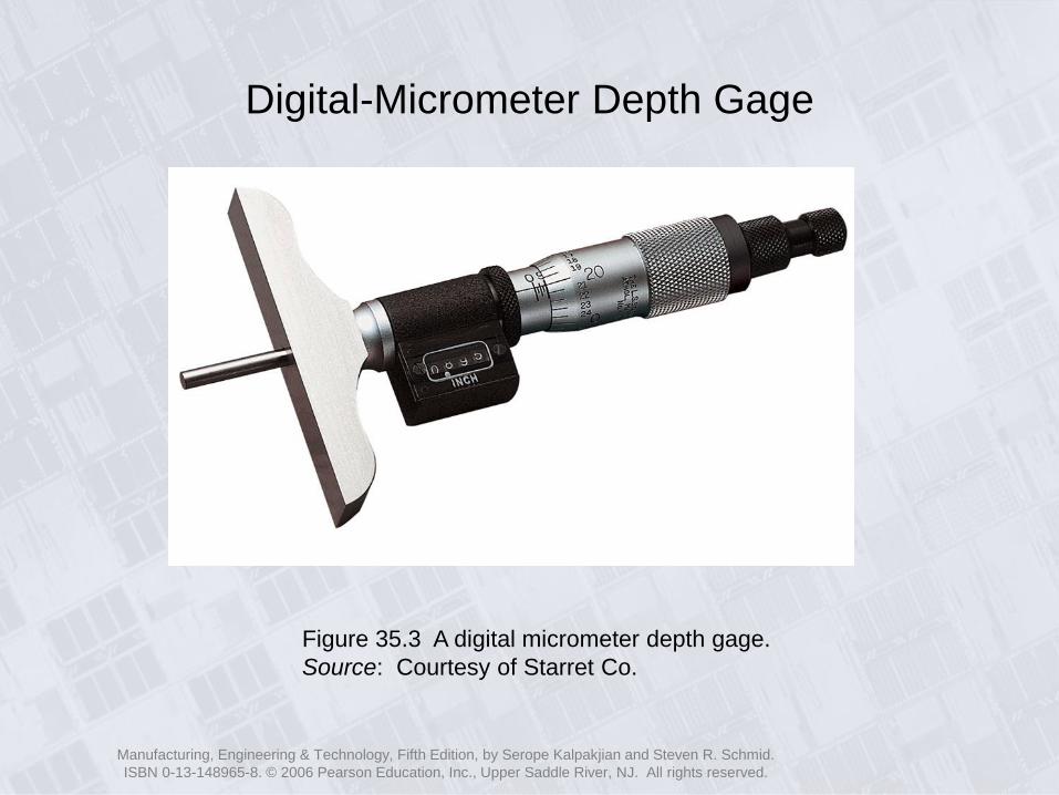
Dial Indicator Uses
Figure 35.4 Three uses of dial indicators: (a) roundess,
(b) depth, and (c) multiple-dimension gaging of a part.

Manufacturing, Engineering & Technology, Fifth Edition, by Serope Kalpakjian and Steven R. Schmid.
ISBN 0-13-148965-8. © 2006 Pearson Education, Inc., Upper Saddle River, NJ. All rights reserved.
Measuring Straightness
Figure 35.5 Measuring straightness manually with (a) a knife-edge rule
and (b) a dial indicator. Source: After F. T. Farago.

Manufacturing, Engineering & Technology, Fifth Edition, by Serope Kalpakjian and Steven R. Schmid.
ISBN 0-13-148965-8. © 2006 Pearson Education, Inc., Upper Saddle River, NJ. All rights reserved.
Measuring Flatness
Figure 35.6 (a) Interferometry method for measuring flatness using an optical flat. (b)
Fringes on a flat, inclined surface. An optical flat resting on a perfectly flat workpiece
surface will not split the light beam, and no fringes will be present. (c) Fringes on a
surface with two inclinations. Note: the greater the incline, the closer together are the
fringes. (d) Curved fringe patterns indicate curvatures on the workpiece surface.
Manufacturing, Engineering & Technology, Fifth Edition, by Serope Kalpakjian and Steven R. Schmid.
ISBN 0-13-148965-8. © 2006 Pearson Education, Inc., Upper Saddle River, NJ. All rights reserved.
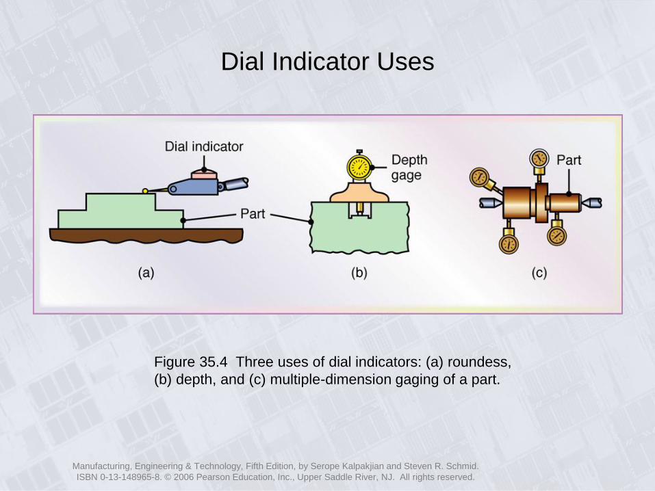
Measuring Roundness
Figure 35.7 (a) Schematic illustration of out-of-roundess (exaggerated). Measuring
roundess using (b) a V-block and dial indicator, (c) a round part supported on
centers and rotated, and (d) circular tracing. Source: After F. T. Farago.
Manufacturing, Engineering & Technology, Fifth Edition, by Serope Kalpakjian and Steven R. Schmid.
ISBN 0-13-148965-8. © 2006 Pearson Education, Inc., Upper Saddle River, NJ. All rights reserved.
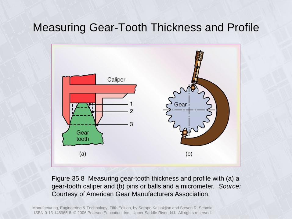
Measuring Gear-Tooth Thickness and Profile
Figure 35.8 Measuring gear-tooth thickness and profile with (a) a
gear-tooth caliper and (b) pins or balls and a micrometer. Source:
Courtesy of American Gear Manufacturers Association.

Manufacturing, Engineering & Technology, Fifth Edition, by Serope Kalpakjian and Steven R. Schmid.
ISBN 0-13-148965-8. © 2006 Pearson Education, Inc., Upper Saddle River, NJ. All rights reserved.
Optical Contour Projector
Figure 35.9 A bench-model horizontal-beam contour projector with a 16-in.
diameter screen with 150-W tungsten halogen illumination. Source: Courtesy of
L. S. Starrett Company, Precision Optical Division.
Manufacturing, Engineering & Technology, Fifth Edition, by Serope Kalpakjian and Steven R. Schmid.
ISBN 0-13-148965-8. © 2006 Pearson Education, Inc., Upper Saddle River, NJ. All rights reserved.
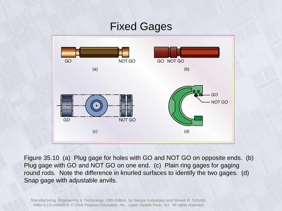
Fixed Gages
Figure 35.10 (a) Plug gage for holes with GO and NOT GO on opposite ends. (b)
Plug gage with GO and NOT GO on one end. (c) Plain ring gages for gaging
round rods. Note the difference in knurled surfaces to identify the two gages. (d)
Snap gage with adjustable anvils.
Manufacturing, Engineering & Technology, Fifth Edition, by Serope Kalpakjian and Steven R. Schmid.
ISBN 0-13-148965-8. © 2006 Pearson Education, Inc., Upper Saddle River, NJ. All rights reserved.
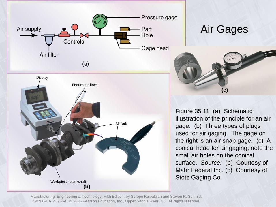
Air Gages
Figure 35.11 (a) Schematic
illustration of the principle for an air
gage. (b) Three types of plugs
used for air gaging. The gage on
the right is an air snap gage. (c) A
conical head for air gaging; note the
small air holes on the conical
surface. Source: (b) Courtesy of
Mahr Federal Inc. (c) Courtesy of
Stotz Gaging Co.
(b)
(c)

Manufacturing, Engineering & Technology, Fifth Edition, by Serope Kalpakjian and Steven R. Schmid.
ISBN 0-13-148965-8. © 2006 Pearson Education, Inc., Upper Saddle River, NJ. All rights reserved.
Electronic Gage
Figure 35.12 An electronic gage for measuring bore
diameter. The measuring head is equipped with three
carbide-tipped steel pins for wear resistance. The LED
display reads 29.158 mm. Source: Courtesy of TESA SA.

Manufacturing, Engineering & Technology, Fifth Edition, by Serope Kalpakjian and Steven R. Schmid.
ISBN 0-13-148965-8. © 2006 Pearson Education, Inc., Upper Saddle River, NJ. All rights reserved.
Electronic Gage Measuring Vertical Length
Figure 35.13 An electronic vertical-
length measuring instrument with a
resolution of 1 μm (40 μin). Source:
Courtesy of TESA SA.
Manufacturing, Engineering & Technology, Fifth Edition, by Serope Kalpakjian and Steven R. Schmid.
ISBN 0-13-148965-8. © 2006 Pearson Education, Inc., Upper Saddle River, NJ. All rights reserved.
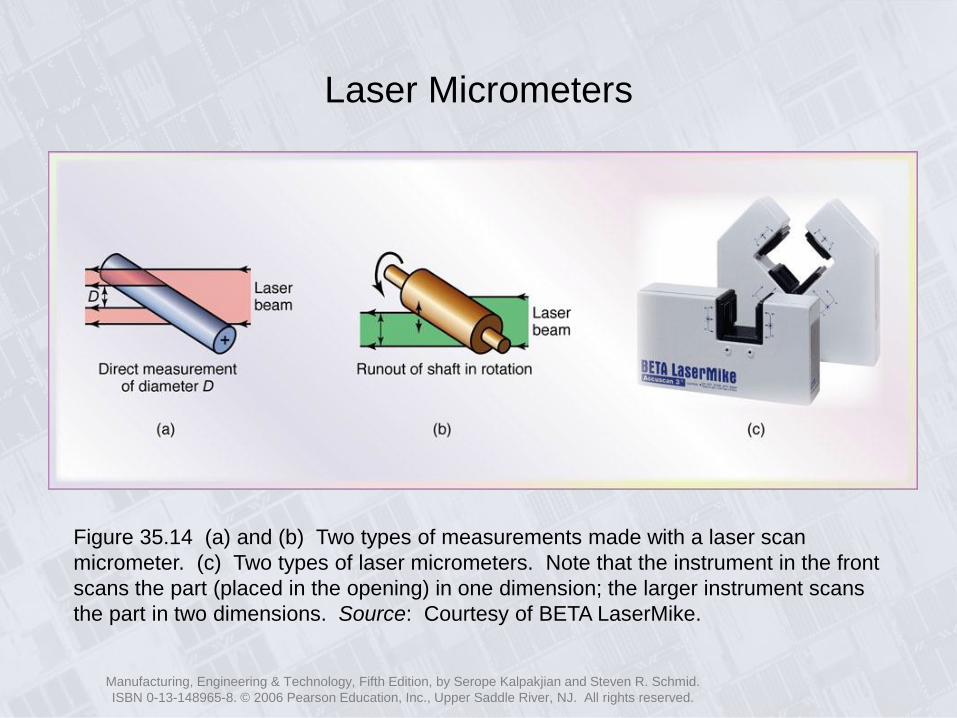
Laser Micrometers
Figure 35.14 (a) and (b) Two types of measurements made with a laser scan
micrometer. (c) Two types of laser micrometers. Note that the instrument in the front
scans the part (placed in the opening) in one dimension; the larger instrument scans
the part in two dimensions. Source: Courtesy of BETA LaserMike.

Manufacturing, Engineering & Technology, Fifth Edition, by Serope Kalpakjian and Steven R. Schmid.
ISBN 0-13-148965-8. © 2006 Pearson Education, Inc., Upper Saddle River, NJ. All rights reserved.
Coordinate-
Measuring Machine
Figure 35.15 (a) Schematic illustration of a coordinate-measuring machine. (b) A touch
signal probe. (c) Examples of laser probes. (d) A coordinate-measuring machine with a
complex part being measured. Source: (b) through (d) Courtesy of Mitutoyo Corp.
(b) (c) (d)

Manufacturing, Engineering & Technology, Fifth Edition, by Serope Kalpakjian and Steven R. Schmid.
ISBN 0-13-148965-8. © 2006 Pearson Education, Inc., Upper Saddle River, NJ. All rights reserved.
Coordinate-Measuring Machine for Car Bodies
Figure 35.16 A large coordinate-measuring machine with two heads measuring
various dimensions on a car body. Source: Courtesy of Mitutoyo Corp.
Manufacturing, Engineering & Technology, Fifth Edition, by Serope Kalpakjian and Steven R. Schmid.
ISBN 0-13-148965-8. © 2006 Pearson Education, Inc., Upper Saddle River, NJ. All rights reserved.
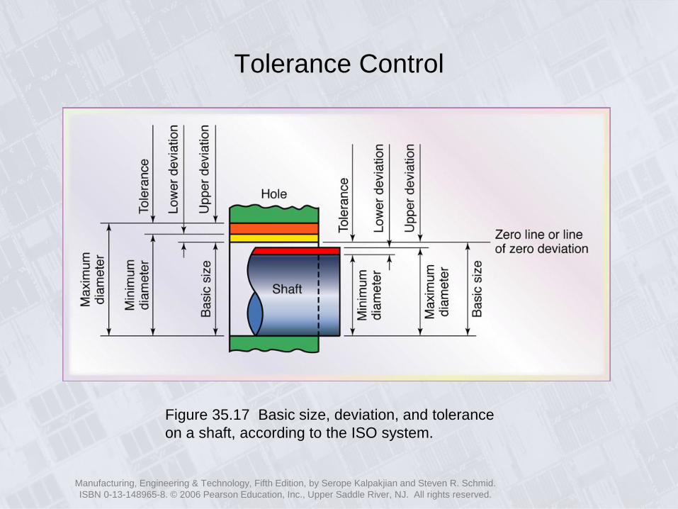
Tolerance Control
Figure 35.17 Basic size, deviation, and tolerance
on a shaft, according to the ISO system.

Manufacturing, Engineering & Technology, Fifth Edition, by Serope Kalpakjian and Steven R. Schmid.
ISBN 0-13-148965-8. © 2006 Pearson Education, Inc., Upper Saddle River, NJ. All rights reserved.
Methods of Assigning Tolerances
Figure 35.18 Various methods of assigning tolerances on a shaft:
(a) bilateral tolerance, (b) unilateral tolerance, and (c) limit dimensions.
Manufacturing, Engineering & Technology, Fifth Edition, by Serope Kalpakjian and Steven R. Schmid.
ISBN 0-13-148965-8. © 2006 Pearson Education, Inc., Upper Saddle River, NJ. All rights reserved.
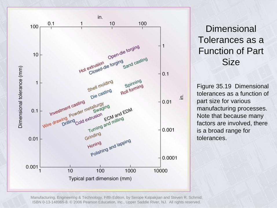
Dimensional
Tolerances as a
Function of Part
Size
Figure 35.19 Dimensional
tolerances as a function of
part size for various
manufacturing processes.
Note that because many
factors are involved, there
is a broad range for
tolerances.
Manufacturing, Engineering & Technology, Fifth Edition, by Serope Kalpakjian and Steven R. Schmid.
ISBN 0-13-148965-8. © 2006 Pearson Education, Inc., Upper Saddle River, NJ. All rights reserved.
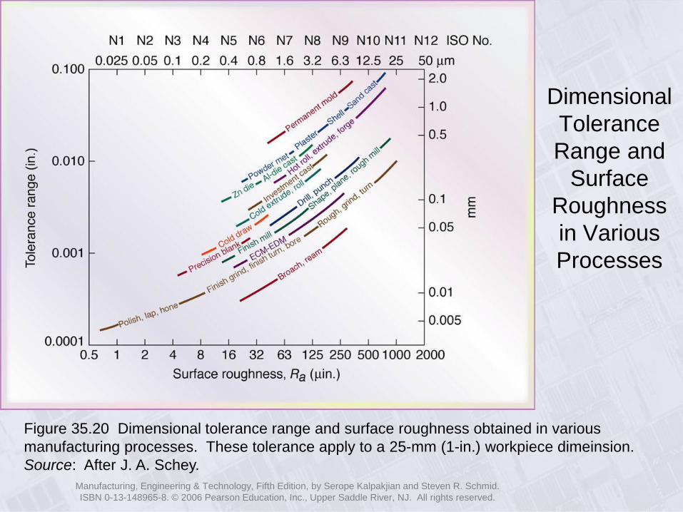
Dimensional
Tolerance
Range and
Surface
Roughness
in Various
Processes
Figure 35.20 Dimensional tolerance range and surface roughness obtained in various
manufacturing processes. These tolerance apply to a 25-mm (1-in.) workpiece dimeinsion.
Source: After J. A. Schey.

Manufacturing, Engineering & Technology, Fifth Edition, by Serope Kalpakjian and Steven R. Schmid.
ISBN 0-13-148965-8. © 2006 Pearson Education, Inc., Upper Saddle River, NJ. All rights reserved.
Engineering Drawing
Symbols
Figure 35.21 Geometric characteristic
symbols to be indicated on engineering
drawings of parts to be manufactured.
Source: Courtesy of The American Society
of Mechanical Engineers.