Engineering Failure Analysis - Università Iuav di · PDF fileEngineering Failure...
23
Resisting system and failure modes of masonry domes Paolo Foraboschi Dipartimento Architettura Costruzione Conservazione, Università IUAV di Venezia, Venice, Italy article info Article history: Received 25 October 2013 Received in revised form 1 May 2014 Accepted 6 May 2014 Available online 23 May 2014 Keywords: Brunelleschi’s dome Dome’s failure Force-resisting system Palladio’s dome Vasari’s dome abstract The research synthesized in this paper focused on ultimate strength, structural safety assessment, and collapse of masonry domes. Activity was directed at analyzing the relationships between safety factor and geometry, and carrying out research targeted at reducing the incidence and severity of structural failures in cultural buildings. This paper shows that the resisting system of a masonry dome is not the two-dimensional shell, but a one-dimensional mechanism that derives from the splitting of the shell and drum. The resisting system, whose geometry depends on the dome shape and brick or stone pat- tern, may include the lantern and/or the masonry constructions around the drum. Well-known domes taken from architectural cultural heritage are used to exemplify the pivotal role of geometry and construction techniques in providing ultimate strength. These examples also show the importance of considering the architectural design of the time, in structural analyses. The results found in the paper suggest how to provide masonry domes with adequate safety, using the minimal level of structural intervention; in particular, without altering the way the building reacts to applied loads. Hence, the paper helps understand how to reduce the amount of structural work, which, in turn, guarantees conservation and resto- ration, as well as safeguarding. The conclusions are devoted to analyzing which observations are valid for seismic assessment and how the other observations have to be modified for seismic actions. Ó 2014 Elsevier Ltd. All rights reserved. 1. Introduction This paper is devoted to masonry domes, with special reference to those of buildings deemed important to the culture— especially history and architecture—of an area, i.e. cultural buildings and architectural heritage. In order to take advantage of architectural heritage, every building must undergo safety assessment, though cultural buildings have survived for centuries. In fact, on one hand masonry degradation due to aging has marginal structural effects, but on the other hand a building may have suffered from structural damage [1–5] (earthquakes [6–13], overloadings [14–18], soil or foundation failure [2,6,7,11,14,19]). Moreover, safety demand is higher than in the past, and longevity does not ensure that safety of the building complies with modern codes [1,3,6–8,10,19,20]. Taking advantage of architectural heritage also requires some cultural buildings to undergo change of occupancy or remodeling, because the modern use of historical buildings is different from the original use. These two needs must satisfy the requirements of safeguarding, renovation, and conservation, which however are in conflict with each other. http://dx.doi.org/10.1016/j.engfailanal.2014.05.005 1350-6307/Ó 2014 Elsevier Ltd. All rights reserved. E-mail address: [email protected] Engineering Failure Analysis 44 (2014) 315–337 Contents lists available at ScienceDirect Engineering Failure Analysis journal homepage: www.elsevier.com/locate/engfailanal
Transcript of Engineering Failure Analysis - Università Iuav di · PDF fileEngineering Failure...

Engineering Failure Analysis 44 (2014) 315–337
Contents lists available at ScienceDirect
Engineering Failure Analysis
journal homepage: www.elsevier .com/locate /engfai lanal
Resisting system and failure modes of masonry domes
http://dx.doi.org/10.1016/j.engfailanal.2014.05.0051350-6307/� 2014 Elsevier Ltd. All rights reserved.
E-mail address: [email protected]
Paolo ForaboschiDipartimento Architettura Costruzione Conservazione, Università IUAV di Venezia, Venice, Italy
a r t i c l e i n f o
Article history:Received 25 October 2013Received in revised form 1 May 2014Accepted 6 May 2014Available online 23 May 2014
Keywords:Brunelleschi’s domeDome’s failureForce-resisting systemPalladio’s domeVasari’s dome
a b s t r a c t
The research synthesized in this paper focused on ultimate strength, structural safetyassessment, and collapse of masonry domes. Activity was directed at analyzing therelationships between safety factor and geometry, and carrying out research targeted atreducing the incidence and severity of structural failures in cultural buildings. This papershows that the resisting system of a masonry dome is not the two-dimensional shell,but a one-dimensional mechanism that derives from the splitting of the shell and drum.The resisting system, whose geometry depends on the dome shape and brick or stone pat-tern, may include the lantern and/or the masonry constructions around the drum.
Well-known domes taken from architectural cultural heritage are used to exemplify thepivotal role of geometry and construction techniques in providing ultimate strength. Theseexamples also show the importance of considering the architectural design of the time, instructural analyses.
The results found in the paper suggest how to provide masonry domes with adequatesafety, using the minimal level of structural intervention; in particular, without alteringthe way the building reacts to applied loads. Hence, the paper helps understand how toreduce the amount of structural work, which, in turn, guarantees conservation and resto-ration, as well as safeguarding.
The conclusions are devoted to analyzing which observations are valid for seismicassessment and how the other observations have to be modified for seismic actions.
� 2014 Elsevier Ltd. All rights reserved.
1. Introduction
This paper is devoted to masonry domes, with special reference to those of buildings deemed important to the culture—especially history and architecture—of an area, i.e. cultural buildings and architectural heritage.
In order to take advantage of architectural heritage, every building must undergo safety assessment, though culturalbuildings have survived for centuries. In fact, on one hand masonry degradation due to aging has marginal structural effects,but on the other hand a building may have suffered from structural damage [1–5] (earthquakes [6–13], overloadings[14–18], soil or foundation failure [2,6,7,11,14,19]). Moreover, safety demand is higher than in the past, and longevity doesnot ensure that safety of the building complies with modern codes [1,3,6–8,10,19,20].
Taking advantage of architectural heritage also requires some cultural buildings to undergo change of occupancy orremodeling, because the modern use of historical buildings is different from the original use.
These two needs must satisfy the requirements of safeguarding, renovation, and conservation, which however are inconflict with each other.
316 P. Foraboschi / Engineering Failure Analysis 44 (2014) 315–337
Safeguarding, which consists of protecting human lives and cultural heritage, aims at prolonging the life of historical con-structions to the utmost. Thus, when structural safety results to be inadequate, safeguarding calls for a structural interven-tion [11,15,20–23].
Renovation, which consists of modifying the building or part thereof, aims at meeting the present occupants’ needs. Thus,when the original architecture is not compatible with the present use, renovation calls for an architectural intervention[5,16,18].
Conservation, which consists of preserving the cultural aspects of the architectural heritage, aims at retainingauthenticity of buildings’ architectural identity. Thus, conservation calls for interventions that do not alter the building orpart thereof, i.e. that guarantee integrity.
Integrity includes those visual aspects and physical elements that make up the appearance of a building, and that are sig-nificant to its cultural value. In particular, integrity includes the overall shape of the building, its materials, decorative details,interior spaces, and features, as well as the various aspects of its site and environment (character-defining features).
Nevertheless, integrity is not limited to only this, but it also includes the structure and craftsmanship; to maintain theoriginal structural behavior of the building and the historical construction technique is mandatory for guaranteeing integrity.Accordingly, integrity requires that, after the intervention, the way the building reacts to applied loads is equal to the way itreacted before the intervention. An intervention that modifies the original structural behavior alters the cultural building,compromising its integrity. After such an intervention, the building loses authenticity.
Hence, making use of cultural heritage requires a balance between safeguarding, renovation, and conservation. Balancemeans that the cultural buildings have to be subjected only to interventions that are necessary to guarantee adequate safetyand functionality (minimal intervention). Moreover, balance means that an intervention has not to modify the original struc-tural behavior.
A balance is often not reached in Italy, which is regrettable since Italy has a huge number of cultural buildings of any sort,and is home to the greatest number of UNESCO World heritage sites. Despite the fact that only few countries in the world canboast a collection of cultural buildings as great in magnitude as Italy can, the Italian structural codes devoted to assessmentof existing buildings [24,25] tend to unbalance the equilibrium in favor of safeguarding, which means that conservation ispenalized and renovation is scarcely considered.
1.1. Aims and objectives of the research
Highlighted, are the new requirements for existing masonry structures that have been adopted by a number of codes of thenew generation [26], in particular in Italy [24,25]. These codes consider only the least common denominator in the structuralbehavior of masonry constructions, which is the load-carrying capacity due to the masses. In so doing, codes ignore architect’sinitial design intentions and disregard specific construction techniques and devices, which lead to a substantial underestima-tion of the safety factor.
These requirements are suitable for new masonry buildings, where steel bars and beams reinforce the masonry elements,but are inappropriate for cultural buildings, which are made of unreinforced masonry. Unacceptable cultural and economicalpenalty could be imposed to architectural heritage should assessment allow only for the load-carrying capacity provided by themasses.
Thus, there is an acute need for a new code approach that allows architectural heritage to be assessed differently fromnew buildings. With reference to masonry domes, on one hand there are a great number of consolidated research findings(too many to be cited individually), but on the other hand they have not been incorporated into practice.
Considering this, activity was directed at carrying out research that advances the state-of-the-practice on masonrydomes. This paper provides material to identify and assess the actual resisting system of masonry domes, which is differentfrom that recognized by the codes.
2. Review of the structural behavior of the masonry arch
In masonry structures, typically, compression stresses are drastically lower than crushing strength [3,8,13–16,20,22,27–30]. Thus, crushing is not a significant mode of failure for masonry structures, excluding columns made of poor masonryor subjected to moisture and salt crystallization.
In masonry structures, tension stresses, including the principal stresses due to shear stresses, reach tension strength innumerous points. Thus, cracking of masonry is a common phenomenon [2,3,7,15,19,20,23,30–32]. Under the higher loads, thus,masonry is cracked and tension stresses are redundant. Therefore, the ultimate load is carried by compression and shear stres-ses only. It follows that failure occurs when a load causes the masonry structure to turn into an unstable mechanism, rather thanwhen a load induces excessive stresses into the masonry.
At the ultimate, a masonry structure behaves as an assemblage of rigid blocks, which passes from a stable to an unstablestate as the load increases and surpasses the ultimate load. Thus, the load-carrying capacity of a masonry structure fundamen-tally depends on the points that the loads are applied to and on the shape of the mechanism that the structure converts into.
Conversely, a masonry structure does not primarily fail due to a lack of material strength; however, compression strengthand tension strength influence the load-carrying capacity. Masonry compression strength influences the distance of each rota-tion pin from the edge of the cross-section. In masonry arches and domes, however, this distance is almost always negligible.

P. Foraboschi / Engineering Failure Analysis 44 (2014) 315–337 317
Masonry tension strength influences how the structure splits into blocks. For some types of masonry structures, which includethe domes, the resisting system strongly depends on tension strength.
In domes, hence, masonry compression strength has a marginal role, while masonry tension strength has a pivotal role.Unfortunately, codes allow for masonry compression strength (to evaluate the aforementioned distance of the pin), but donot allow for masonry tension strength.
Considering that masonry tension strength does not depend on the materials (Section 4), the load-carrying capacity ofarches and domes do not depend on the mechanical characteristics of bricks (or stones) and mortar that the structure is madeof.
The failure modes can be grouped into rotating and translating shapes. The rotating shapes consist of rigid blocks joinedby hinges placed at the vertexes of each rigid block; the translating shapes, of a part that slides with respect to the other part.In the case of masonry arches and domes, the failure modes can also be grouped into shapes with fixed springing sections(Figs. 1 and 2) or with the springing sections that translate laterally (Figs. 3 and 4). Contrary to the former shapes, the lattershapes involve the abutments. Figs. 1–4 show symmetric structures and loads. In actual fact, real structures and real loadsare not symmetric. Thus, the mechanisms are not symmetric; so, each shape has one hinge less. On one hand, this does notmodify the theoretical developments; on the other hand, however, symmetric failure modes allow the presentation to bemore expressive.
2.1. No-tension friction assumption for safety assessment
The ultimate behavior of masonry structures is typically analyzed under the no-tension friction assumption: The materialhas no tension strength, infinite compression strength, and shear strength equal to the normal force multiplied by the fric-tion coefficient of masonry ([4,12,13,16,22,29,35]).
This assumption allows safety to be assessed with the path of the resultants of the compression stresses through themasonry, called line of thrust [36] (Figs. 5 and 6). In fact, the no-tension assumption implies that each point of the thrustline has a distance from the axis of the structure that is equal to the ratio between the couple and the normal force inthe section. This ratio is called eccentricity, e (Fig. 5). The thrust line is a viable means for assessing safety of the masonryarch [28,29,35].
Given the arch, there are infinite thrust lines in equilibrium with a given load. The real thrust line is the one that respectsthe two boundary conditions at the springing—namely, the horizontal thrust, Hs, and the bending moment. Since the verticalreaction is statically determinate, the springing bending moment can be expressed by the eccentricity of the springing nor-mal force, es (Fig. 5). However, the lower bound theorem allows safety assessment to ignore Hs and es, since ultimate strengthanalysis does not require the real thrust line [37].
If a line of thrust can be found for the arch which is in equilibrium with the external loading (including own weight),which lies everywhere within the masonry of the arch, whose tangent lies everywhere within the friction angle, and whosespringing thrust does not cause the failure of the abutments, then the structure is stable. Using the symbols represented inFig. 5, the above statement can be synthesized by the following formulas:
Fig. 1.downwand the
eðuÞ < t2
0 6 u 6 �u ð1Þ
hðuÞ 6 arctgðlÞ 0 6 u 6 �u ð2Þ
Hs 6 Fab ð3Þ
Masonry arch and abutments. Kinematic mechanism that does not involve the abutments; the springing sections are fixed and the crown movesards. In the figure, both the structure and load are symmetric. In reality, structures and loads are not symmetric. Thus, the hinge h5 does not formhinge and h3 is not exactly at the crown; moreover, h2 and h4 are not symmetric. The actual form is that of Fig. 7.

Fig. 2. Kinematic mechanism that does not involve the abutments; the springing sections are fixed and the crown moves upwards. In the figure, both thestructure and load are symmetric. In reality, structures and loads are not symmetric. Thus, the hinge h5 does not form and h3 is not exactly at the crown;moreover, h2 and h4 are not symmetric (Fig. 7).
Fig. 3. Kinematic mechanism that involves the abutments; the springing sections and abutments open, while the crown moves downwards. The aspectratio of the abutments is greater than 0.5, and therefore the sliding mechanism of the abutment cannot occur. In the figure, both the structure and load aresymmetric. In real conditions, however, the hinge h5 does not form and h3 is not exactly at the crown; moreover, h2 and h4 are not symmetric.
318 P. Foraboschi / Engineering Failure Analysis 44 (2014) 315–337
where �u is the maximum angular coordinate u (polar angle, which in Figs. 5 and 6 is p), l is the masonry friction coefficient,and Fab is the force at the common boundary between arch and abutment that causes the failure of the abutment. A thrustline that satisfies (1–3) is called compatible.
The (1–3) prove that safety assessment does not require the real locus of the centroid of the compression stresses as theyflow from section to section, but a locus in each section that may guarantee the equilibrium between the external load andthe internal actions. According to (1–3), in fact, Hs and es can be chosen arbitrarily, and these values remain unknown, apartfrom the ultimate condition [37].
The line of thrust can also be applied ignoring the ultimate thrust of the abutment Fab. The arch and abutments are able tobear the load if a thrust line is placed within the masonry thickness of both the arch and abutments, and within the frictionangle [28,29,35–40].
If it is impossible to place a thrust line totally inside the thickness t of the arch (Fig. 6a), the structure is unstable (the solearch or the arch and abutments). The failure mode is a rotation mechanism, which may (Figs. 3 and 4) or may not (Figs. 1 and2) involve the abutments. In fact, a stress resultant N that acts outside the cross-section of the arch can be equilibrated onlyby an internal tension force, F, together with the internal compression force C in the masonry cross-section (Fig. 6a). If alsothe tension force F acts at the edge of the cross-section (e.g., external reinforcement [15,21,22,39,41]):
Nðua 6 u 6 ubÞ ¼ CðuÞ � FðuÞ2 � e � N � ua 6 u 6 ubð Þ ¼ t � CðuÞ þ FðuÞ½ �
�ð4Þ
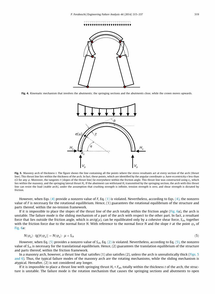
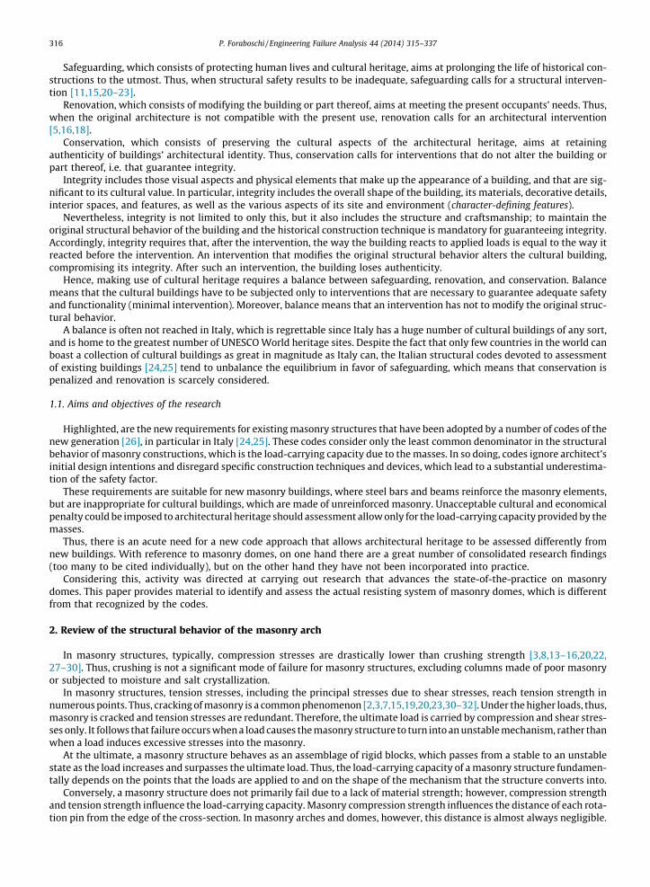
Fig. 4. Kinematic mechanism that involves the abutments; the springing sections and the abutments close, while the crown moves upwards.
Fig. 5. Masonry arch of thickness t. The figure shows the line containing all the points where the stress resultants act at every section of the arch (thrustline). This thrust line lies within the thickness of the arch. In fact, these points, which are identified by the angular coordinate u, have eccentricity e less thant/2 for any u. Moreover, the tangents h (slopes of the thrust line) lie everywhere within the friction angle. This thrust line was constructed using es, whichlies within the masonry, and the springing lateral thrust Hs. If the abutment can withstand Hs transmitted by the springing section, the arch with this thrustline can resist the load (stable arch), under the assumption that crushing strength is infinite, tension strength is zero, and shear strength is dictated byfriction.
P. Foraboschi / Engineering Failure Analysis 44 (2014) 315–337 319
However, when Eqs. (4) provide a nonzero value of F, Eq. (1) is violated. Nevertheless, according to Eqs. (4), the nonzerovalue of F is necessary for the rotational equilibrium. Hence, (1) guarantees the rotational equilibrium of the structure andparts thereof, within the no-tension framework.
If it is impossible to place the slopes of the thrust line of the arch totally within the friction angle (Fig. 6a), the arch isunstable. The failure mode is the sliding mechanism of a part of the arch with respect to the other part. In fact, a resultantforce that lies outside the friction angle, which is arctg(l), can be equilibrated only by a cohesive shear force, Sch, togetherwith the friction force due to the normal force N. With reference to the normal force N and the slope h at the point ua ofFig. 6a:
NðuaÞ � tg½hðuaÞ� ¼ NðuaÞ � lþ Sch ð5Þ
However, when Eq. (5) provides a nonzero value of Sch, Eq. (2) is violated. Nevertheless, according to Eq. (5), the nonzerovalue of Sch is necessary for the translational equilibrium. Hence, (2) guarantees the translation equilibrium of the structureand parts thereof, within the friction framework.
In a masonry arch, however, a thrust line that satisfies (1) also satisfies (2), unless the arch is unrealistically thick (Figs. 5and 6). Thus, the typical failure modes of the masonry arch are the rotating mechanisms, while the sliding mechanism isatypical. Hereafter, (2) is not considered any longer.
If it is impossible to place a thrust line with springing thrust Hs < Fab, totally within the thickness t of the arch, the struc-ture is unstable. The failure mode is the rotation mechanism that causes the springing sections and abutments to open
Fig. 6. Two different thrust lines constructed for each arch. Each thrust line, identified by the labels 1 and 2 respectively, is in equilibrium with the appliedload, including the initial conditions. (a) Thrust line 1 is contained entirely within the masonry and therefore it satisfies inequality (1); moreover, it alsosatisfies inequality (2). If the springing lateral thrust associated with thrust line 1 satisfies inequality (3), the arch bears the load and so it is stable.Conversely, thrust line 2 passes outside the masonry; in particular, it violates inequality (1) from the point ea of coordinate ua to the point eb of coordinateub. Moreover, it does not lie within the friction angle too; in particular, the tangent violates inequality (2) around the points ea and eb. Thrust line 2 provesneither that the arch is stable nor that the arch is unstable. (b) Two thrust lines constructed starting from the same point of the springing section. Thrust line1 uses the springing thrust Hs1; thrust line 2 uses the springing thrust Hs2. Since both e1 and e2 are lower than t/2 for 0 6 u 6 p, either thrust line guaranteesthe equilibrium of the arch under the applied load. Generally, none of them is the real thrust line, since the starting point and lateral thrust at the springingare not real (unless by an unrealistic coincidence). However, safety assessment does not require the real thrust line.
Fig. 7. Virtual work done by the applied load and weight over the displacement produced by the mechanism in the figure. The weights Pj whose centroidmoves downwards and the forces Fi applied to the boundaries that move downwards belong to the external loading system; and, conversely, the weights Pj
whose centroid moves upwards and the forces Fi applied to the boundaries that move upwards belong to the resisting system. The loads applied toboundaries that do not move, do not participate in the ultimate limit state of the structure.
320 P. Foraboschi / Engineering Failure Analysis 44 (2014) 315–337
(Fig. 3). Theoretically, the opening of the springing sections can be caused by the shear failure of the abutment. In this case,the kinematic of the abutment is the sliding rather than the rotation. However, the sliding mechanism of the abutment lies atthe bottom level of the strength hierarchy only if the aspect ratio of the abutment (i.e., the ratio of height of the abutment towidth of the abutment) is less than 2.0, which is uncommon in masonry arches and domes. Therefore, the sliding mode offailure of the abutment is ignored hereafter. Hence, (3) ensures the rotation and translation equilibrium of the abutments.
The kinematically admissible displacements include the failure modes with the springing sections that close (Fig. 4),which is important for the arch but irrelevant for the dome (Section 3).
Ultimately, to demonstrate that the arch will stand as a structure, it is necessary and sufficient to find at least one thrustline that satisfies (1) and (3), which, in turn, satisfies (2) automatically.
Thrust lines constructed starting from different values of Hs are different from each other (Fig. 6b). Nevertheless, everycompatible thrust line proves that the load does not cause the structure to collapse.

P. Foraboschi / Engineering Failure Analysis 44 (2014) 315–337 321
Eqs. (1) and (3) prove that the middle-third rule [29] is wrong. To place the thrust line within the middle-third has nomeaning, since the thrust line that lies within the middle-third is not the real one, but one of the infinite compatible thrustlines. That a masonry arch is uncracked, however, is pointless, since the ultimate behavior implies cracks.
The no-tension friction model also allows the safety of masonry arches to be assessed considering that, at collapse, thearch consists of rigid bodies connected to one another by hinges placed at the boundaries (pinning mechanism). The virtualwork theorem proves that a masonry arch under the weights P and the forces F collapses if and only if, for at least a mech-anism (Fig. 7) [33]:
XN
i¼1
Fi � dFi þXN
j¼1
Pj � dPj > 0 ð6Þ
where N is the number of rigid blocks, Fi is the force applied to the i-th block, Pj is the own weight of the j-th block, and d arethe virtual displacements produced by the mechanism; in particular, dFi of the application point of Fi in the direction of Fi, anddPj of the j-th centroid in the vertical direction. A vertical force is positive if it points down; a vertical displacement is positiveif it is directed downwards. A horizontal force is positive if it points to the right (left); a horizontal displacement is positive ifit is directed to the right (left).
2.2. No-tension friction assumption for ultimate load assessment
The no-tension friction assumption implies that a masonry arch is an internally statically unstable structure, whose fail-ure is not due to lack of material strength but to equilibrium only.
Since e, h, and Fab depend on the application points but not on the level of the total load, the safety factor of a masonryarch depends on the distribution but not on the level of the total load. Thus, the sum of own weight, dead loads, and liveloads cannot express the safety factor of the masonry arch.
Conversely, the safety factor of the masonry arch is measured by the ratio between the ultimate value and design value ofthe imposed loads; the imposed loads consist of the live loads, but they also have to include some dead loads, when they canchange during the service life.
The ultimate load is the higher level of the imposed load for which it is possible to place the thrust line within the archand abutments, independently of the distribution of the imposed load.
Consequently, there is only one thrust line in equilibrium with the ultimate load, which therefore is the real thrust line.From the thrust line perspective, hence, the ultimate limit state represents an exception.
At the ultimate, the thrust line is tangent to the extrados and intrados of the arch in either 3 or 4 points:
Hs < Fab ! eðukÞ ¼t2
for k ¼ 1; . . . ;4 ð7Þ
Hs P Fab ! eðukÞ ¼t2
for k ¼ 1; . . . ;3 ð8Þ
Contrary to what shown in Figs. 1–4, Eqs. (7) and (8) consider that the real structures and loads are never symmetric.Accordingly, a mechanism always has four hinges, which can be located either only in the arch or three in the arch andone in an abutment. Eqs. (7) and (8) show the role of cracking in masonry. Any thrust line with e(u) 6 t/6, which is a nec-essary (but not sufficient) condition for masonry to be uncracked, equilibrates a load that is inferior to the ultimate load.Hence, the same phenomenon seen from the displacement perspective is cracking and seen from the force perspective istransmitting the higher levels of bending moment.
The ultimate load of a masonry arch is also the minimum level of the imposed load that triggers a rotation mechanism inthe structure and/or its supports. The ultimate load can be expressed by the minimum multiplier k of the imposed load F forwhich a mechanism and a distribution of the imposed load F satisfy the following equation, which derives from (6):
XN
i¼1
k � Fi � dFi þXN
j¼1
Pj � dPj ¼ 0 ð9Þ
In (9), as the structure moves through the virtual displacement, the application point of Fi undergoes the displacement dFi
in the direction of the force (in general Fi may also have a horizontal component), and the centroid of the weight Pj undergoesthe vertical displacements dPj (Fig. 5).
The minimum k has to be found by applying (9) to all the kinematically admissible mechanisms and using all the possibleapplication points of Fi. Hence, the assemblage of rigid blocks that Eq. (9) must be applied to, may or may not involve theabutments. In the former case (Fig. 3), the sum of the N forces Pj is equal to the weight of the arch plus either the abutmentsor parts thereof. In the latter case (Figs. 1 and 2), the sum of the N forces Pj is equal to the weight of the sole arch.
Eq. (9) shows that the load-carrying capacity of a masonry arch is dictated by the weakest mechanism, which forms whenthe most severe distribution of the imposed load reaches a certain value (ultimate load).

322 P. Foraboschi / Engineering Failure Analysis 44 (2014) 315–337
3. Structural behavior of the masonry dome
The loads (including own weight) induce meridian (arch) and parallel (circumferential or hoop) stresses in a dome[35,40]. The meridian stresses are always compressions. The parallel stresses are tensions in the lower part of the domeand compressions in the upper part (except for the atypical case of domes with flat crown and heavy lantern).
The maximum parallel tension stress is usually at the springing and very often it reaches masonry tension strength evenunder the dead load. Hence, masonry domes are typically cracked, and cracking occurs immediately after the construction(sometimes during the construction). Cracking initiates at the springing and propagates vertically downwards into the drumand upwards toward the crown, sometimes arresting at the haunches while at other times approaching the crown[3,4,7,13,29,30,41–43].
Parallel tension stresses exist only until they crack the masonry. Hence, vertical cracking transforms the dome from atwo-dimensional to a one-dimensional structure. Considering that the vertical cracks are typical, the masonry dome is a shellonly from the architectural point of view, while it is a system of arches from the structural point of view.
Stability of masonry arches is governed by two parameters—namely, the thickness-to-span ratio, and the lateral springingthrust [33,37]. Considering that the cracked dome behaves as a masonry arch, it follows that stability of masonry domes isgoverned by these two parameters.
The thickness of a masonry dome is that of the arches it splits into, due to vertical cracking. Thus, the thickness-to-spanratio (first parameters) does not refer to the thickness of the shell but it depends on the shape of the curved elements that theshell splits into.
In a masonry dome, the abutment coincides with a block that the drum is split into, due to vertical cracking. Therefore,the lateral springing thrust (second parameters) is the horizontal thrust transmitted by the cracked dome to the crackeddrum through the parallel with the lowest latitude.
There is a minimum thickness-to-span ratio for any masonry arch [33,37]. Thus, a masonry dome is stable only if thethickness of the arches that it splits into is greater than the minimum thickness for the span.
If, conversely, the thickness-to-span ratio is less than the minimum, the dome is unstable. In this case, there are two pos-sible failure modes. In both of them, the springing parallel is fixed (no lateral displacement); in the first one, the crownmoves downwards (Fig. 1), while in the second one, the crown moves upwards (Fig. 2).
The minimum thickness-to-span ratio and the failure mode depend on the shape of the dome and the brick pattern. Safetyassessment and design of the structural intervention require prior knowledge of the minimum thickness-to-span ratio andthe mode that dictates the failure.
The lateral springing thrust of an arch has to lie within a range of values that depends on the geometry and loading. Thelower bound of this range is called ‘‘lower thrust’’ [37]. Thus, a masonry dome is stable only if the lateral thrust transmittedthrough the springing parallel is greater than the lower thrust (and less than the upper bound). Considering also the lowerbound theorem, a masonry dome is stable only if the lower thrust is inferior to the horizontal thrust that causes the failure ofthe drum.
If, conversely, the lower thrust is greater than the maximum lateral thrust that the drum can bear, the dome and the drumare unstable. In this case, the mode of failure is demonstrated by the opening of the drum and springing parallel togetherwith the downward translation of the crown (Fig. 3).
The drum, even if buttressed, is not a thrust structure. Hence, the dome cannot be subjected to a springing thrust greaterthan the upper bound of the range of possible lateral thrusts. Consequently, the thrust cannot trigger the failure mode bywhich the drum and springing parallel close, while the crown translates upwards (Fig. 4).
The lower thrust depends on the shape of the dome and the brick (stone) pattern. The lower thrust of the dome needs tobe known for the safety assessment and design of the structural intervention.
3.1. Failure mode hierarchy for the masonry dome
The ultimate behavior of a masonry dome can be analyzed more easily by using the virtual work theorem than the thrustline. To this end, (9) has to be written for the arches that result from the splitting of the dome and to include the lantern andthe structures around the drum (if they exist).
Let M denote the number of curved elements that the dome and drum split into or will split into (i.e., M is the number ofmeridian cracks). Eq. (9) turns into:
PL � dPL þXM
k¼1
XN
i¼1
k � Fi � dFi þXM
k¼1
XN
j¼1
Pj � dPj ¼ Lvb ð10Þ
where PL is the weight of the lantern at the crown of the dome, and dPj is the virtual vertical displacement of the crown due tothe infinitesimal movement of the considered mechanism. A vertical force is positive if it points down; a vertical displace-ment is positive if it is directed downwards; and vice versa. A horizontal force is positive if it points to the right (left); a hor-izontal displacement is positive if it is directed to the right (left). The term Lvb is the virtual work done by the buttressingaction of the structures around the drum or by circumferential belts, due to the virtual displacement of the mechanism.

P. Foraboschi / Engineering Failure Analysis 44 (2014) 315–337 323
Eq. (10) has to be applied to all the kinematically admissible mechanisms of the dome split into arches. For each mech-anism, all the possible application points of the force F have to be considered in (10). The mechanism and load distributionthat provide the minimum value of k are the failure mode and the load-carrying capacity of the dome, respectively.
When (10) is applied to a mechanism that does not involve the drum or if the drum is neither buttressed nor strengthenedwith belts, Lvb = 0. When (10) is applied to a mechanism that involves the drum, the weights Pj include pieces of drum andthe forces Fi may be applied to the drum.
3.2. Failure mode hierarchy for the masonry dome
In masonry domes, the top level of the strength hierarchy is occupied by the translation mechanism (Section 2.1). Accord-ingly, the shear action does not interest the masonry domes [33,37]. Thus, the bottom levels in the strength hierarchy areoccupied by the rotation mechanisms.
The strength hierarchy of the rotation mechanisms depends on the lateral strength of the drum, which, in turn, dependson the thickness of the drum and on the presence of buttresses or circumferential strengthening elements (steel tie-rods ortimber belts).
If the drum is thick, buttressed or strengthened, the rotation mechanisms with fixed springing lie at the lowest levels inthe hierarchy. More specifically, the lowest level is occupied by the mechanism with the crown that moves downwards(Fig. 1) in the case of hemispherical domes, and that moves upwards (Fig. 2) in the case of domical domes.
If the drum is thin and neither buttressed nor strengthened, the mechanism with the drum and springing parallel thatopen while the crown moves downwards lies at the lowest levels in the hierarchy (Fig. 3).
4. New approach for safety assessment of masonry domes
Section 3 has demonstrated how to analyze the masonry dome in the framework of the masonry arch. However, Eq. (10)can be applied only to domes with meridian cracks, i.e. to a dome split into arches. In order to assess the safety of the domesnot yet cracked, and to interpret the splitting of the cracked domes, it is necessary to predict how an uncracked masonryshell will split into arches.
4.1. From the two-dimensional masonry shell to a system of arches
The thickness t of the arches that barrel, cross or groin masonry vaults split into, almost never depends on the position ofthe cracks. Thus, the minimum k obtained by applying (9) to whatever system of arches that a structure can split into is theload-carrying capacity. The mechanism associated with k is the resisting system.
Conversely, the thickness t of the arches into which the domes split depends on the position of the meridian cracks. Thus,the minimum k obtained by applying (10) to a possible system of arches into which a dome can split is not necessarily theload-carrying capacity, and the mechanism associated with k is not necessarily the resisting system.
The position of the meridian cracks depends on tension stresses and strength. Thus, the no-tension assumption (Section 2)has to be replaced by an assumption that allows the actual crack position to be considered or predicted.
Masonry tension strength at the material level is very low, but at the level of the brick or stone pattern may be consid-erable, and indeed it was considered by past architects and master masons. In fact, sometimes, the brick patterns weredesigned and laid to maximize the interaction between the masonry units. As a result, in masonry domes, tension stressesare one order of magnitude greater than the tension strength of the mortar, but are of the same order of magnitude of thetension strength of the brick (stone) pattern. The tension strength of a brick or a stone is greater than the tension strength ofthe pattern; thus, the former does not dictate the capacity of carrying tension forces.
During a relative rotation, crack opening is not resisted by interlocking and friction; in this case, thus, tension strengthdoes not provide any contribution to the load-carrying capacity. During a relative translation, conversely, crack openingmay be resisted by interlocking and friction; in this case, thus, tension strength provides considerable contributions.
The splitting of the dome can be governed by adding to Eq. (10) a term that allows for the virtual work done by the ten-sion stresses provided by the masonry unit pattern, Lvc. During a virtual relative translation, the stress profile by which thebrick (stone) pattern resists the opening of a crack is uniform; its value is equal to the tension strength, fmt, and this tensionstress is smeared onto the area that is involved in the relative translation, whose shape is rectangular.
Lvc ¼XM
k¼1
bk � tk � dk � fmt ð11Þ
where M is the number of meridian sections that undergo relative horizontal translation d. Moreover, bk and tk are the lengthand the thickness, respectively, of the k-th area that is involved in the relative translation. If the thickness of the dome doesnot taper, tk is the same for all the areas (i.e., tk does not depend on k).
4.2. Small-tension-strength assumption
Eq. (11) has to be inserted into Eq. (10):
324 P. Foraboschi / Engineering Failure Analysis 44 (2014) 315–337
PL � dPL þXM
k¼1
XN
i¼1
k � Fi � dFi þXM
k¼1
XN
j¼1
Pj � dPj ¼ Lvb þXM
k¼1
b � t � dk � fmt ð12Þ
Eq. (12) was applied to several brickwork domes that exhibited meridian cracks. This analysis adopted fmt = 0.01 N/mm2
for the crack openings resisted by interlocking and friction, and fmt = 0 in the other cases. Although 0.01 N/mm2 is a very lowvalue, this analysis proved that cracks nevertheless form where the tension strength is zero. In these cases, tension strengthhas a direct role in the ultimate behavior of the dome, since it forces the dome to split where crack opening is not resisted byinterlocking and friction. But the ultimate behavior of the dome split into arches does not depend on tension strength. Thus,the load-carrying capacity can be predicted by using (10), since Lvc = 0 for the dome split into arches.
In many domes, however, whatever meridian crack that can open is resisted by interlocking and friction, because thedome does not exhibit any discontinuity in tension strength; therefore, no zone of the dome has marginal tension strength,i.e. masonry tension strength has a uniform distribution over the dome and its value is everywhere not small. In order toanalyze how these domes split into arches, a second analysis was carried out. This analysis calibrated the value of fmt inEq. (12) against the actual cracks observed in the analyzed domes. The result is that fmt = 0.05 N/mm2 well represents thetension strength provided by interlocking and friction.
5. The structural role of the lantern
A dome is crowned by a lantern through which daylight is admitted into the interior and which can be uses as a belve-dere. However, the lantern may have a significant structural role too.
If the virtual work performed by the weight of the lantern over the kinematic of a binding mechanism is positive, the lan-tern belongs to the external load system; conversely, if the virtual work is negative, the lantern belongs to the load resistingsystem (Fig. 7).
5.1. Hemispherical masonry dome
During the binding mechanisms of the hemispherical masonry dome (i.e., those shown in Figs. 1 and 3), the crown alwaystranslates downwards. Thus, the virtual work done by the lantern, LvL, is:
LvL ¼ PL � dPL > 0 ð13Þ
Let qj denote the weight of the j-th block of unitary thickness (rather than thickness t). The virtual work done by the shellwith unitary thickness, lv1(t = 1) over the mechanism that does not involve the drum (with fixed springing) while the crowntranslates downwards is (Fig. 1):
lv1ðt ¼ 1Þ ¼XN
j¼1
qj � dPj < 0 ð14Þ
Considering that the weight Pj of the j-th block is Pj = t�qj, the combination of (13) and (14) provides a necessary conditionto prevent the triggering of the failure mechanism of Fig. 1:
LvL þ t � lv1 6 0 ! t > � PL � dPLPNj¼1qj � dPj
ð15Þ
Inequality (15) represents a necessary condition for stability of the dome, but not sufficient. If (14) is not respected, thedome collapses, demonstrating the failure mode by which the crown translates downwards while the springing parallel andthe drum does not move (Fig. 1).
The thickness t of the shell not only has to satisfy (14), but it has to exceed the right member as much as necessary so thatEq. (10) provides a k greater than the value associated with the design live loads.
The virtual work done by the shells with unitary thickness lv1 during the mechanism that involves the drum (with thespringing parallel the opens), while the crown translates downwards is (Fig. 3):
lv1ðt ¼ 1Þ ¼XN
j¼1
qj � dPj > 0 ð16Þ
The virtual work done by the drum during this mechanism, LvD, is negative (which is obvious, since the other contribu-tions are positive). Thus, LvD has to counterbalance the positive contributions of lantern and shell:
LvD P t �XN
j¼1
qj � dPj þ PL � dPL ð17Þ
In order to satisfy (17), the drum has to have an adequate thickness; if it is not thick enough, it has to be buttressed orstrengthened with belts.

P. Foraboschi / Engineering Failure Analysis 44 (2014) 315–337 325
Ultimately, the heavier the lantern, the heavier the shell has to be to prevent the mechanism with fixed springing (Fig. 1).Moreover, the heavier the lantern and the shell, the greater the strength of the drum has to be in order to prevent the open-ing of the springing and drum (Fig. 3). Thus, a hemispherical masonry dome with a heavy lantern needs that the drum isthick or strengthened (by buttressing structures or belts). On the contrary, a hemispherical masonry dome with a lightweightlantern may be stable also if the drum is not particularly thick and not strengthened.
5.2. Domical masonry dome
During the binding mechanisms of the domical masonry dome (i.e., those shown in Figs. 2 and 3), the crown may translatedownwards or upwards:
LvL ¼ PL � dPL < 0 ð18-aÞ
LvL ¼ PL � dPL > 0 ð18-bÞ
where Eq. (18-a) describes the failure mode that does not involve the drum, (springing parallel fixed; Fig. 2), and Eq. (18-b)describes the failure mode that involves the drum (springing parallel that opens; Fig. 3).
The virtual work done by the domical shell of unitary thickness for the mechanism that does not involve the drum is(Fig. 2):
lv1ðt ¼ 1Þ ¼XN
j¼1
qj � dPj < 0 ð19Þ
The combination of (18-a) and (19) proves that the mechanism with fixed springing cannot occur in the masonry domicaldome with constant thickness, whatever the weight of the lantern.
In numerous domical domes, however, the shell tapers in thickness over the span, from the springing to the crown. If thecrown is thin, Eq. (19) does not hold true any longer, and the virtual work done by the shell, Lvs, is positive. In this case, theweight PL of the lantern has to be great enough to counterbalance the positive virtual work done by the shell for the mech-anism with fixed springing parallel (Fig. 2):
LvL þ Lvs < 0 ! � PL � dPL >XN
j¼1
Pj � dPj ð20Þ
For tapered domical dome, the weight PL of the lantern not only has to satisfy (20) over the mechanism with fixed spring-ing (Fig. 2), but it also has to exceed the right member as much as necessary so that Eq. (10) provides a k greater than thevalue associated with the design live loads.
The virtual work done by the shell for the mechanism where the springing parallel and the drum translate laterally andopen is (Fig. 3):
Lvs ¼XN
j¼1
Pj � dPj > 0 ð21Þ
According to (18-b) and (21), both the lantern and the shell do positive virtual work over the mechanism of Fig. (3). Thus,the mechanism with the springing parallel and drum that translate laterally is resisted only by the drum, as for the hemi-spherical dome. However, all other parameters being equal, the virtual work done by the domical shell and lantern is lessthan that of the hemispherical shell and lantern. This result can be immediately derived combining the shapes of the domesand the slopes of the thrust lines that lie within the thickness of each geometry. Thus, the drum of a domical dome may notbe as strong as the drum of the hemispherical dome.
Ultimately, in the domical dome the lantern plays two dual roles—namely, it belongs to the resisting system in the mech-anism with fixed springing but it belongs to the load system in the mechanism with the springing parallel and drum thatopen. In the tapered domical dome, the lantern has to be heavy enough to prevent the formation of the mechanism withfixed springing but lightweight enough to prevent the formation of the mechanism with the springing parallel and drum thatopen.
5.3. The lantern of real historic domes
Architects and master builders (master masons) knew the effects of the lantern on a masonry dome [2,6–9,11–14,16,29,32,35,42,44].
One example is the dome of the temple of Villa Barbaro (Fig. 8), in Maser, near Treviso (Italy), which was designed byAndrea Palladio and was built between 1554 and 1580 (in 1560 for many historians).
This dome is a hemispherical masonry shell. Palladio’s plan for the temple included a large and massive lantern at thecrown. However, Palladio had realized that a lightweight lantern was mandatory for the equilibrium of the dome. Thus,he rejected the idea of a lantern made of marble. In fact, the great weight of a large marble lantern either would have

Fig. 8. Dome of the temple of Villa Barbaro in Maser, a little town near Treviso (Italy). The temple, including the dome, was designed by Andrea Palladio. Thefigure shows the hemispherical masonry dome over Palladio’s temple of Villa Barbaro. The large lantern of the dome is made of timber; thus, it is not asheavy as its massive form would suggest.
Fig. 9. Dome of the Santa Maria del Fiore cathedral, in Florence (Italy), designed by Filippo Brunelleschi. The masonry dome over the Florence cathedral iscomposed of ribs and webs: octagonal ribbed domical dome. The lantern, which is a belvedere about 20 m high, is made of marble. Thus, Brunelleschi’slantern is heavy.
326 P. Foraboschi / Engineering Failure Analysis 44 (2014) 315–337

P. Foraboschi / Engineering Failure Analysis 44 (2014) 315–337 327
triggered the mechanism with fixed springing section (Fig. 1) or would have requested a thick shell that would have trig-gered the mechanisms with the springing section that opens (involving the drum). Palladio put his idea into effect by usinga timber lantern that imitated a typical marble lantern (Fig. 8).
This research has confirmed Palladio’s supposition. With a marble lantern, Eq. (10) applied to the mechanism with fixedspringing (Fig. 1) gives a negative value of k. Conversely, with a timber lantern, Eq. (10) gives:
k ¼4 �PN
j¼1Pj � dPj � PL � dPL
4 �PN
i¼1Fi � dFi
¼ 0:13 �XN
j¼1
Pj ð22Þ
The forces Fi are the resultant forces that derive from a uniformly distributed load applied to the dome. Eq. (22) considersthe actual cracking pattern of the dome, which exhibits four uniformly spaced meridian cracks that pass through the entirethickness. The four cracks initiate at the four openings of the windows located at the springing of the dome; each crackextends vertically from the top of the opening up to the bottom of the crown, and from the bottom of the opening to thebase of the drum. Hence, the four meridian cracks cut the entire thickness of the drum, springing, and haunches; only thecrown is not cracked. Thus, Eq. (22) was obtained by applying Eq. (10) to the four arches of identical geometry that the domeis split into. Accordingly, in this dome, the two summations of (10) add four identical terms; i.e., M = 4 in Eq. (10).
Another example is the dome of Santa Maria del Fiore cathedral in Florence (Italy), which was built by Filippo Brunelleschibetween 1420 and 1436 (Fig. 9). This is an octagonal ribbed domical masonry dome.
History of architecture explains that the gothic style of this dome is due to the fact that the competition to complete thechurch of Santa Maria del Fiore, held in 1418, was not for the design of a new dome. In fact, the competition won by Brun-elleschi was for the construction of a dome according to the preliminary design that had already been accomplished in theprevious century by Giovanni di Lapo Ghini. Moreover, history of architecture explains that Brunelleschi did not refine thepreliminary design toward the contemporary style also because the dome had to match the gothic style of the church and torest upon an octagonal drum (the church had been built in the XIV century, and the drum had been built together thechurch). Although these style requirements, however, the rise of the dome could have been reduced and/or less emphasiscould have been put on the intersections between the webs (ribs).
Contrary to what history of architecture tells, Brunelleschi maintained the preliminary design because it was the solutionto all the problems that he had to face and overcome. In particular, Brunelleschi knew that a lower rise and weaker ribs at thecorners would have not provided the dome with adequate strength against the mechanism where the springing parallelopens. This inadequacy would have been emphasized by the heavy lantern that Florentine wanted to crown the dome(not designed yet).
The Florentine dome tapers in thickness over the span, from the springing to the crown. This research found that the vir-tual work done by the shell (i.e., without the lantern) for the mechanism with fixed springing parallel is negative, althoughthe crown is thinner than the springing section. This behavior did not happen by chance, but it was the result of some precisedecisions made by Brunelleschi. On one hand, the less the crown thickness the less the springing thrust; on the other hand,however, a domical dome with a very thin crown cannot bear its own weight, unless it is topped by a heavy lantern. Brun-elleschi knew the empirical aspects of these rules; consequently, he saved all the weight that was not strictly required by thedome to prevent the failure mode of Fig. 2 from triggering when the dome did not have the lantern yet. To this end, thedegree of taper was not pronounced at the crown. In so doing, the dome resisted the failure mode of Fig. 2; moreover,the lower thrust necessary to prevent the failure mode of Fig. 3 from triggering was reduced to the minimum.
Brunelleschi knew that his dome would have guaranteed the equilibrium against the mechanism with fixed springing(Fig. 2) not only without the lantern, but also without the crown, because he thought that the dome would not have splitinto vertical one-dimensional elements during the construction work. It was on the basis of this conviction that he proposedto build the dome without temporary falsework (without centering). In particular, Brunelleschi decided to lay the bricksalong the parallels, rather than along the meridians. This construction technique implied to build the dome in subsequentrings from the springing to the crown, rather than in subsequent arches starting from the ribs and ending with the webs.The construction work of the shells was completed in 1436. The lantern was positioned in 1471, after the death ofBrunelleschi.
The preliminary design of the dome developed in the XIV century did not include the lantern, but only the idea of crown-ing the dome with a belvedere. Another competition was held for the lantern, which again was won by Brunelleschi. WhenBrunelleschi designed the lantern he knew that stability did not require that weight; but above all, he knew that the heavierthe lantern the greater the lateral springing thrust. On one hand, he designed the lantern that the Florentine expected, whichallowed him to win the competition. On the other hand, however, he had realized that he had to solve the problem of thetransmission of the lateral thrust between dome and drum through the springing, although the dome was domical, since thelantern that he was about to design would have been heavy and the drum was relatively thin and had eight large eyes.
6. Drum and buttresses
The structural system formed by the masonry dome and drum (tambour) that the dome rests upon is stable only if themaximum springing thrust that the drum can bear is greater than the lower thrust of the dome. If conversely the lateral

Fig. 10. Not only does this thrust line satisfies inequalities (1) and (2), since the thrust line is entirely contained within the arch, but it also satisfies (3),since it is also entirely contained within the abutments. Therefore, the structure is stable under the applied load.
Fig. 11. In this masonry system, every thrust line that lies within the arch does not lie within the abutments, and vice versa. Since it is impossible to place athrust line entirely within the masonry, this structure is unstable under this load. Failure occurs with the mode of Fig. 3, i.e. the abutments and springingsections open and the crown moves downwards.
328 P. Foraboschi / Engineering Failure Analysis 44 (2014) 315–337
thrust-carrying capacity of the drum does not exceed the lower thrust, the system cannot prevent the formation of the mech-anism with the springing parallel and drum that open (Fig. 3).
The comparison between the hemispherical and domical shapes shows that, at the springing, the slope of the thrust lineof the former (Fig. 10) is less than that of the latter (Fig. 11), all other things being equal. Thus, the hemispherical dome has alower thrust greater than the domical dome. Hence, the drum of the hemispherical dome has to be thicker than that of thedomical dome, and may require buttresses or belts (Figs. 10 and 11).

P. Foraboschi / Engineering Failure Analysis 44 (2014) 315–337 329
6.1. The drum in real historic domes
Andrea Palladio wanted that the dome of the temple of Villa Barbaro had neither buttresses nor external circumferentialbelts (Fig. 8). Although the dome was hemispherical, Palladio however was able to reach the target, since he had realized thatthe less the weight of dome and lantern the less the lower thrust. Thus, Palladio designed the dome and lantern by using theminimum weight that was possible.
There was hence another reason why the lantern was made as lightweight as possible, in addition to the reason explainedin Section 5.3—namely, also to provide the temple dome with adequate safety margin against the mechanism shown in Fig. 3.
The minimum thickness-to-span ratio for the hemispherical masonry dome without lantern is 1/32 [33,37]. The timberlantern in imitation of a marble lantern (Section 5.3) increased that limit value only marginally. Moreover, the brick patternadopted by Palladio decreased that limit value (Section 7). Thus, Palladio could assign to the dome a thickness even less thanthe minimum; the thickness-to-span ratio of this temple dome is 1/34 of the span. In so doing, Palladio made the dome aslightweight as possible, which reduced the demand for springing thrust.
However, Palladio also wanted a thin drum. To this end, Palladio’s plan for the temple of Villa Barbaro included an internalmasonry annular beam at the top of the drum, encircling the springing. The masonry annular beam is a brickwork curvedbeam whose brick pattern is designed so that the parallel tension forces are resisted by friction stresses exchanged betweenthe bricks and by tension stresses in the bricks. Therefore, the masonry annular beam (which seems a combination of con-tradictory terms) requires no help from the mortar, which can even be cracked.
The encircling action provided by the masonry annular beam allowed Palladio to further reduce the thickness of thedrum, as desired.
The competition won by Brunelleschi for the dome of the Santa Maria del Fiore Cathedral in Florence did not allow the newdesign to modify the drum and lateral chapels, which had already been built in the previous century.
Brunelleschi knew that the dome he was designing was atypical, since it was very thick and would have carried a heavylantern; moreover, the drum was not particularly thick and had eight large eyes. Therefore, the lower thrust of the dome wasa huge problem to solve.
The first key design criterion was that the less the weight of the dome the less the value of the lower thrust. To this end,Brunelleschi’s plan included an inner and an outer shell held together with a ring and rib system, where a significant fractionof the volume was empty. Hence this dome is like a honeycomb sandwich structure. According to Brunelleschi’s plan, more-over, the two shells gradually tapers in thickness over the span, from the springing to the crown, which further reduced thetotal weight. In so doing, the lower thrust was much less than that of the same dome composed of a unique shell.
In addition, Brunelleschi incorporated into the dome a series of wooden and stone chains, which run round the circum-ference, encircling the dome where the thrusting action was high. Unlike external belts, these circumferential rings wereinvisible, since they were buried in the dome’s masonry. These construction techniques further reduced the lower thrust.
Although the drum was buttressed by the nave and chapels around the dome’s octagon, however the above solutionswere insufficient to guarantee the equilibrium of the dome. Fortunately, Brunelleschi had realized that the design still lackedsomething.
7. The structural role of brick pattern
Meridian (i.e., vertical) cracks that pass through the entire thickness should be considered as intrinsic to a masonry dome,since the own weight of the structure is sufficient to cause meridian cracking [2,3,6–9,13–19,31,32,35,40–47].
The circumferential stresses induced by the dead loads are substantially constant along each parallel and reach the max-imum at the springing. Thus, a vertical crack initiates in the point of the springing where tension strength is minimum andpropagates vertically, cutting the entire masonry thickness, upwards toward the crown and downwards into the drum.
As aforementioned, the mortar may crack even under very low tension stresses [1,4,10,11,16,17,20,22,23,30,36,43,45–47]. Nevertheless, the mechanism of interlocking and friction between the bricks (stones) allows masonry to transmitsignificant tension stresses also when the mortar is cracked [34,48]. Therefore, the maximum value that the tension stresscan reach is dictated only by the brick (stone) pattern (i.e., the disposal of bricks or stones). This means that masonry tensionstrength is dictated neither by the mortar, which may provide irrelevant tension stresses, nor by the brick (stone), which hastension strength greater than the pattern.
Hence, the points along the springing where vertical cracks initiate depend on the brick (stone) pattern, which thereforedictates the shape of the cross-section of the arches that the masonry dome splits into.
The ultimate behavior of a masonry dome depends only on the ultimate behavior of these arches, which, in turn, dependson the thickness of their cross-section. The thickness of the cross-section is the distance between the rotation axis of thepins at the extrados and intrados. Hence, the position of the meridian (vertical) cracks influences the ultimate behavior ofthe dome.
A dome with circular plan splits into arches whose cross-section is an annular sector. The greater the tension strength ofthe brick pattern the greater the distance between two consecutive vertical cracks, and, in turn, the greater the central angleof the annular sector. The angle of the annular sector dictates the thickness of the arches that the dome splits into. Thus, thestronger the brick pattern the greater t of (1). The empirical aspects of this relationship were known by architects and mastermasons.

passing-
through crack
passing-
through crack
passing-
through crack
passing-
through crack
corner crack
nave
Fig. 12. Crack pattern of the Florence dome (survey of Professor Andrea Chiarugi, who first provided a scientific interpretation of the behavior of theBrunelleschi’s dome, including the construction technique). Every other web of the dome is cracked: Four cracks that cut the entire thickness of the twoshells in the middle of the web. The dome exhibits other cracks (e.g., in the vertexes, called corner cracks), but these cracks do not pass through the entirethickness (they form pins). Conversely, the four cracks in the figure cut the dome from its inner to its outer surfaces, from the base of the drum to the crown.Therefore, only the four cracks in the webs dictate how the dome splits into arches and the dome’s ultimate behavior, while the other cracks do notinfluence structural safety.
330 P. Foraboschi / Engineering Failure Analysis 44 (2014) 315–337
In order to investigate the role of the brick pattern in domes with circular plan, Villa Barbaro’s temple dome (Fig. 8) wasanalyzed by using (10); the virtual work done by the shell and lantern as they move through the displacements of the failuremode shown in Fig. 3 provided the lower thrust. Eq. (10) was applied both to the actual arches that the dome is split into,whose geometry had been obtained by a survey, and to the arches that the dome would have been split into according to theno-tension assumption, whose geometry prevented the development of tension stresses. More specifically, Eq. (10) wasapplied both to four identical arches whose cross-section was a circular annulus with central angle equal to 90 degrees,and to arches whose cross-section was a circular annulus with infinitesimal central angle. In the former case, (10) usedthe thickness t that had been provided by the survey of the dome; in so doing, (10) obtained the actual lower thrust, whichis the result of how the dome had cracked. Conversely, in the latter case, (10) used the thickness t of the shell; in so doing,(10) obtained the lower thrust that the dome would have had if cracking had produced the weakest resisting system. Thedifference between the former and latter lower thrust quantifies the role of the brick pattern in this dome.
The actual value of the lower thrust resulted to be 0.144 of the total weight of dome plus lantern. The lower thrust accord-ing to the no-tension assumption resulted to be 0.361 of the total weight of dome plus lantern. Contrary to the former value,the latter value could not have been counterbalanced by the drum of the temple, which is thin and not buttressed.
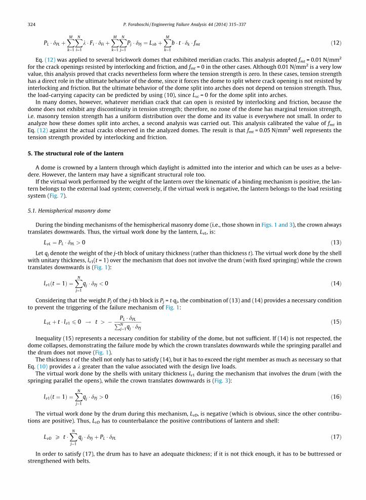
A dome with polygonal plan (e.g., the ribbed domical dome) splits into arches whose cross-section has a shape thatdepends on whether the vertical (meridian) cracks initiate at the ribs or in the webs (Figs. 12 and 13). If cracking initiatesand develops at the ribs (Fig. 14), the cross-section of each arch is a rectangle with the thickness of the web (which is thethickness of the dome). Conversely, if cracking initiates and develops in the webs, the cross-section of each arch is a com-posite geometric figure with a thickness substantially greater than that of the dome (Fig. 13). Accordingly, both the thick-ness-to-span ratio and lower thrust of a dome with polygonal plan drastically depend on the position of the vertical cracks.
If the bricks (stones) are laid onto horizontal planes, the component of the meridian forces parallel to a mortar joint doesnot lie within the friction angle (sliding failure). Thus, the bricks (stones) have to lie along the thickness of the dome, so thatthe face of each masonry unit and each mortar joint are orthogonal to the meridian forces.
A web of a polygonal masonry dome is composed of bricks or stones that lie in continuous rows (courses of bricks orstones); each course starts at a rib and ends at the consecutive rib. If a course lies both along the thickness of the domeand along a parallel, this course lies on one plane. However, the courses that form a parallel of the dome, each one in itsweb, lie on planes different from each other, i.e., a different plane per web. The only exception is when the tangent to therib is vertical (as it usually is at the springing section). Apart from this exception, hence, the intersection at a rib of two con-secutive courses of the same parallel does not lie on a plane: The planes tangent to the course on the right and left of a rib aredifferent from one another.
Hence, if the courses are laid along the parallels of the dome, the faces of the bricks (stones), respectively, on the right andon the left of a rib form an angle different from the straight angle. In this case, the courses exhibit a discontinuity of tangentat the ribs. This angular discontinuity of the brick pattern causes the tension strength at a rib to be very low; in particular, itjust reaches the tension strength of the mortar.
Ultimately, if the brick (stone) courses are laid along the parallels of the dome, the contiguous webs are not connected toone another; so, the brick pattern provides the ribs with marginal capacity of bearing parallel (hoop) tension forces.
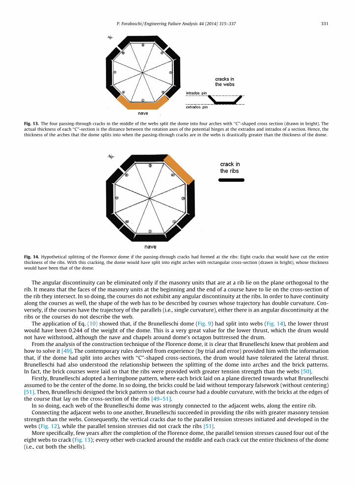
Fig. 13. The four passing-through cracks in the middle of the webs split the dome into four arches with ‘‘C’’-shaped cross section (drawn in bright). Theactual thickness of each ‘‘C’’-section is the distance between the rotation axes of the potential hinges at the extrados and intrados of a section. Hence, thethickness of the arches that the dome splits into when the passing-through cracks are in the webs is drastically greater than the thickness of the dome.
Fig. 14. Hypothetical splitting of the Florence dome if the passing-through cracks had formed at the ribs: Eight cracks that would have cut the entirethickness of the ribs. With this cracking, the dome would have split into eight arches with rectangular cross-section (drawn in bright), whose thicknesswould have been that of the dome.
P. Foraboschi / Engineering Failure Analysis 44 (2014) 315–337 331
The angular discontinuity can be eliminated only if the masonry units that are at a rib lie on the plane orthogonal to therib. It means that the faces of the masonry units at the beginning and the end of a course have to lie on the cross-section ofthe rib they intersect. In so doing, the courses do not exhibit any angular discontinuity at the ribs. In order to have continuityalong the courses as well, the shape of the web has to be described by courses whose trajectory has double curvature. Con-versely, if the courses have the trajectory of the parallels (i.e., single curvature), either there is an angular discontinuity at theribs or the courses do not describe the web.
The application of Eq. (10) showed that, if the Brunelleschi dome (Fig. 9) had split into webs (Fig. 14), the lower thrustwould have been 0.244 of the weight of the dome. This is a very great value for the lower thrust, which the drum wouldnot have withstood, although the nave and chapels around dome’s octagon buttressed the drum.
From the analysis of the construction technique of the Florence dome, it is clear that Brunelleschi knew that problem andhow to solve it [49]. The contemporary rules derived from experience (by trial and error) provided him with the informationthat, if the dome had split into arches with ‘‘C’’-shaped cross-sections, the drum would have tolerated the lateral thrust.Brunelleschi had also understood the relationship between the splitting of the dome into arches and the brick patterns.In fact, the brick courses were laid so that the ribs were provided with greater tension strength than the webs [50].
Firstly, Brunelleschi adopted a herringbone pattern, where each brick laid on a plane directed towards what Brunelleschiassumed to be the center of the dome. In so doing, the bricks could be laid without temporary falsework (without centering)[51]. Then, Brunelleschi designed the brick pattern so that each course had a double curvature, with the bricks at the edges ofthe course that lay on the cross-section of the ribs [49–51].
In so doing, each web of the Brunelleschi dome was strongly connected to the adjacent webs, along the entire rib.Connecting the adjacent webs to one another, Brunelleschi succeeded in providing the ribs with greater masonry tension
strength than the webs. Consequently, the vertical cracks due to the parallel tension stresses initiated and developed in thewebs (Fig. 12), while the parallel tension stresses did not crack the ribs [51].
More specifically, few years after the completion of the Florence dome, the parallel tension stresses caused four out of theeight webs to crack (Fig. 13); every other web cracked around the middle and each crack cut the entire thickness of the dome(i.e., cut both the shells).
332 P. Foraboschi / Engineering Failure Analysis 44 (2014) 315–337
The octagonal drum rests upon four piles; thus, the drum is supported at every other span. Consequently, cracks occurredin the four webs that were not directly supported by the piles. Each crack initiated at the springing and propagated towardsthe crown and into the drum [49–51].
According to Brunelleschi’s plan for the dome, the brick pattern forced the dome to split into arches whose cross-sectionwas composed of a web and half of the two adjacent webs (Fig. 13). The thickness of the ‘‘C’’-shaped cross-section cut downthe lower thrust to a value that could be tolerated by the drum. Thus, the opening of the springing parallel and the drum(Fig. 3) was prevented from occurring. Moreover, the dome was provided with a considerable safety factor. More specifically,the multiplier of the uniformly distributed live load obtained by applying Eq. (10) to the arches of Fig. 13 over the mecha-nisms of Fig. 3, which is the mode that dictates the failure, results to be:
k ¼ �PL � dPL þ
PNj¼1Pj � dPjPN
i¼1Fi � dFi
¼ 0:18 � PL þXN
j¼1
Pj
!ð23Þ
Eq. (23) shows that the Florence dome has a considerable safety factor.Not only was the pivotal role of Brunelleschi’s brick pattern proven theoretically in this research, but it is also field-proven
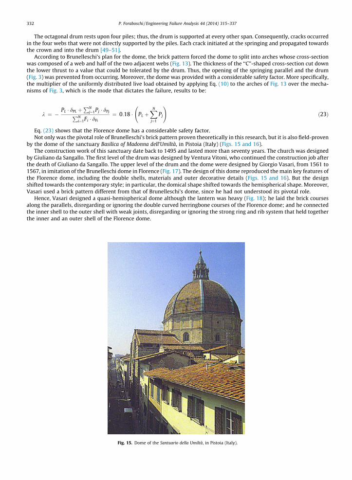
by the dome of the sanctuary Basilica of Madonna dell’Umiltà, in Pistoia (Italy) (Figs. 15 and 16).The construction work of this sanctuary date back to 1495 and lasted more than seventy years. The church was designed
by Giuliano da Sangallo. The first level of the drum was designed by Ventura Vitoni, who continued the construction job afterthe death of Giuliano da Sangallo. The upper level of the drum and the dome were designed by Giorgio Vasari, from 1561 to1567, in imitation of the Brunelleschi dome in Florence (Fig. 17). The design of this dome reproduced the main key features ofthe Florence dome, including the double shells, materials and outer decorative details (Figs. 15 and 16). But the designshifted towards the contemporary style; in particular, the domical shape shifted towards the hemispherical shape. Moreover,Vasari used a brick pattern different from that of Brunelleschi’s dome, since he had not understood its pivotal role.
Hence, Vasari designed a quasi-hemispherical dome although the lantern was heavy (Fig. 18); he laid the brick coursesalong the parallels, disregarding or ignoring the double curved herringbone courses of the Florence dome; and he connectedthe inner shell to the outer shell with weak joints, disregarding or ignoring the strong ring and rib system that held togetherthe inner and an outer shell of the Florence dome.
Fig. 15. Dome of the Santuario della Umiltà, in Pistoia (Italy).
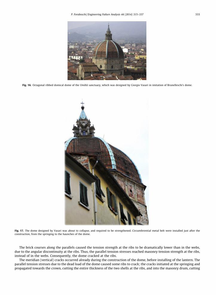
Fig. 16. Octagonal ribbed domical dome of the Umiltà sanctuary, which was designed by Giorgio Vasari in imitation of Brunelleschi’s dome.
Fig. 17. The dome designed by Vasari was about to collapse, and required to be strengthened. Circumferential metal belt were installed just after theconstruction, from the springing to the haunches of the dome.
P. Foraboschi / Engineering Failure Analysis 44 (2014) 315–337 333
The brick courses along the parallels caused the tension strength at the ribs to be dramatically lower than in the webs,due to the angular discontinuity at the ribs. Thus, the parallel tension stresses reached masonry tension strength at the ribs,instead of in the webs. Consequently, the dome cracked at the ribs.
The meridian (vertical) cracks occurred already during the construction of the dome, before installing of the lantern. Theparallel tension stresses due to the dead load of the dome caused some ribs to crack; the cracks initiated at the springing andpropagated towards the crown, cutting the entire thickness of the two shells at the ribs, and into the masonry drum, cutting

Outer shell
Inner
shell
Hemisphericalshape
Actual
shape
Fig. 18. Vertical cross-section of the dome of the Santuario della Umiltà, in Pistoia (Italy). The section cuts the dome and the drum (Survey G. Tucci). Thegraphical construction of the figure shows the deviations of this dome from the hemispherical shape. This graphical construction was performed to provethat this dome is closer to the hemispherical dome than to the domical dome.
334 P. Foraboschi / Engineering Failure Analysis 44 (2014) 315–337
its entire thickness. More specifically, now the dome exhibits eight meridian cracks at the eight ribs; but it is impossible toknow whether all the eight cracks were caused by the own weight of the dome, and therefore all of them occurred during theconstruction, or some of them were caused by the own weight of the dome and the other cracks by the weight of the lantern,and therefore some cracks occurred after its completion.
The cracks at the ribs split the dome into arches with rectangular cross-section, i.e. the section of the web, as in Fig. 14.Hence, the dome splits into arches whose thickness was equal to the thickness of the web (i.e., of the dome), which was verysmall in comparison to the span of the dome.
The consequence of having ignored Brunelleschi’s design was fatal for Vasari’s design (fortunately not for the dome). Thevirtual work theorem proved that the cracked dome and drum could not prevent the formation of the mechanism shown inFig. 3 even without the lantern. In fact, on the assumption that all the eight cracks at the ribs were caused by the own weightof the sole dome, and hence that all the eight cracks had already formed before the lantern was installed:
Fig. 19.lateral
k ¼ �PN
j¼1Pj � dPjPNi¼1Fi � dFi
¼ �0:12 �XN
j¼1
Pj ð24Þ
The negative value of k of (24) confirms that that the dome could not bear even the own weight, since the rectangularcross-section of the arches that the dome had split into implied a lower thrust greater than the maximum value that thedrum could provide the springing with.
Metal tie-rods installed by Bartolomeo Ammannati, four years after the completion of the dome. The tie-rods eliminated the demand of springingthrust of the dome.
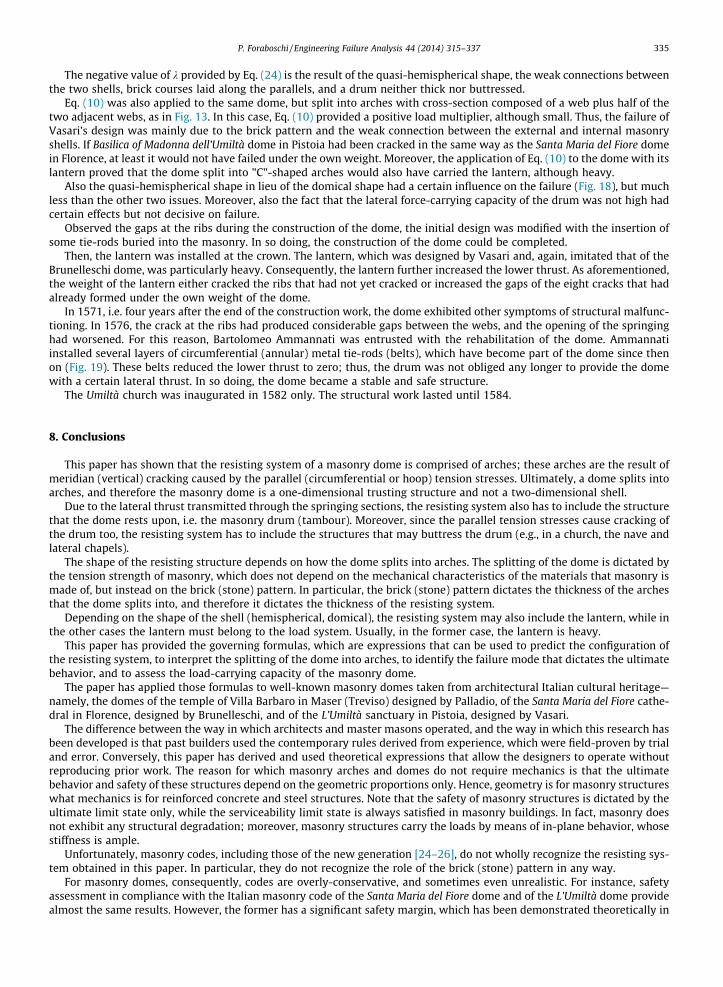
P. Foraboschi / Engineering Failure Analysis 44 (2014) 315–337 335
The negative value of k provided by Eq. (24) is the result of the quasi-hemispherical shape, the weak connections betweenthe two shells, brick courses laid along the parallels, and a drum neither thick nor buttressed.
Eq. (10) was also applied to the same dome, but split into arches with cross-section composed of a web plus half of thetwo adjacent webs, as in Fig. 13. In this case, Eq. (10) provided a positive load multiplier, although small. Thus, the failure ofVasari’s design was mainly due to the brick pattern and the weak connection between the external and internal masonryshells. If Basilica of Madonna dell’Umiltà dome in Pistoia had been cracked in the same way as the Santa Maria del Fiore domein Florence, at least it would not have failed under the own weight. Moreover, the application of Eq. (10) to the dome with itslantern proved that the dome split into "C"-shaped arches would also have carried the lantern, although heavy.
Also the quasi-hemispherical shape in lieu of the domical shape had a certain influence on the failure (Fig. 18), but muchless than the other two issues. Moreover, also the fact that the lateral force-carrying capacity of the drum was not high hadcertain effects but not decisive on failure.
Observed the gaps at the ribs during the construction of the dome, the initial design was modified with the insertion ofsome tie-rods buried into the masonry. In so doing, the construction of the dome could be completed.
Then, the lantern was installed at the crown. The lantern, which was designed by Vasari and, again, imitated that of theBrunelleschi dome, was particularly heavy. Consequently, the lantern further increased the lower thrust. As aforementioned,the weight of the lantern either cracked the ribs that had not yet cracked or increased the gaps of the eight cracks that hadalready formed under the own weight of the dome.
In 1571, i.e. four years after the end of the construction work, the dome exhibited other symptoms of structural malfunc-tioning. In 1576, the crack at the ribs had produced considerable gaps between the webs, and the opening of the springinghad worsened. For this reason, Bartolomeo Ammannati was entrusted with the rehabilitation of the dome. Ammannatiinstalled several layers of circumferential (annular) metal tie-rods (belts), which have become part of the dome since thenon (Fig. 19). These belts reduced the lower thrust to zero; thus, the drum was not obliged any longer to provide the domewith a certain lateral thrust. In so doing, the dome became a stable and safe structure.
The Umiltà church was inaugurated in 1582 only. The structural work lasted until 1584.
8. Conclusions
This paper has shown that the resisting system of a masonry dome is comprised of arches; these arches are the result ofmeridian (vertical) cracking caused by the parallel (circumferential or hoop) tension stresses. Ultimately, a dome splits intoarches, and therefore the masonry dome is a one-dimensional trusting structure and not a two-dimensional shell.
Due to the lateral thrust transmitted through the springing sections, the resisting system also has to include the structurethat the dome rests upon, i.e. the masonry drum (tambour). Moreover, since the parallel tension stresses cause cracking ofthe drum too, the resisting system has to include the structures that may buttress the drum (e.g., in a church, the nave andlateral chapels).
The shape of the resisting structure depends on how the dome splits into arches. The splitting of the dome is dictated bythe tension strength of masonry, which does not depend on the mechanical characteristics of the materials that masonry ismade of, but instead on the brick (stone) pattern. In particular, the brick (stone) pattern dictates the thickness of the archesthat the dome splits into, and therefore it dictates the thickness of the resisting system.
Depending on the shape of the shell (hemispherical, domical), the resisting system may also include the lantern, while inthe other cases the lantern must belong to the load system. Usually, in the former case, the lantern is heavy.
This paper has provided the governing formulas, which are expressions that can be used to predict the configuration ofthe resisting system, to interpret the splitting of the dome into arches, to identify the failure mode that dictates the ultimatebehavior, and to assess the load-carrying capacity of the masonry dome.
The paper has applied those formulas to well-known masonry domes taken from architectural Italian cultural heritage—namely, the domes of the temple of Villa Barbaro in Maser (Treviso) designed by Palladio, of the Santa Maria del Fiore cathe-dral in Florence, designed by Brunelleschi, and of the L’Umiltà sanctuary in Pistoia, designed by Vasari.
The difference between the way in which architects and master masons operated, and the way in which this research hasbeen developed is that past builders used the contemporary rules derived from experience, which were field-proven by trialand error. Conversely, this paper has derived and used theoretical expressions that allow the designers to operate withoutreproducing prior work. The reason for which masonry arches and domes do not require mechanics is that the ultimatebehavior and safety of these structures depend on the geometric proportions only. Hence, geometry is for masonry structureswhat mechanics is for reinforced concrete and steel structures. Note that the safety of masonry structures is dictated by theultimate limit state only, while the serviceability limit state is always satisfied in masonry buildings. In fact, masonry doesnot exhibit any structural degradation; moreover, masonry structures carry the loads by means of in-plane behavior, whosestiffness is ample.
Unfortunately, masonry codes, including those of the new generation [24–26], do not wholly recognize the resisting sys-tem obtained in this paper. In particular, they do not recognize the role of the brick (stone) pattern in any way.
For masonry domes, consequently, codes are overly-conservative, and sometimes even unrealistic. For instance, safetyassessment in compliance with the Italian masonry code of the Santa Maria del Fiore dome and of the L’Umiltà dome providealmost the same results. However, the former has a significant safety margin, which has been demonstrated theoretically in

336 P. Foraboschi / Engineering Failure Analysis 44 (2014) 315–337
this paper, but above all is field-proven by its long lifespan without any treatment. On the contrary, the latter had a negativesafety margin, which has been demonstrated theoretically in this paper, but above all was field-proven by the installation ofexternal metal belts immediately after its construction. For the Italian masonry codes, the Brunelleschi dome would requiremetal circumferential belts at the springing and drum, like those installed around the Vasari dome by Ammannati. The onlyreason why this treatment has been avoided for the Florence dome is that Italian authorities have not prescribed structuralassessment for this dome.
In total opposition was the destiny of the dome of Villa Barbaro’s temple, designed by Palladio. In order to celebrate fivecenturies on from the birth of Palladio, the dome was subjected to restoration, which included a safety assessment. The pointis not whether safety assessment considered the mechanisms, according to the new codes, or the maximum stresses, whichis the approach of the previous Italian code. The point is that also if safety verification had accomplished a mechanism anal-ysis, the result would not have justified the equilibrium of this dome. In fact, the lower thrust, which was here estimatedaccording to the no-tension assumption, resulted in being greater than the maximum thrust that the drum could providethe dome with. In compliance with the present Italian code (or with the past code), hence, a circumferential pre-stressedsteel belt was installed onto the drum just under the springing of the dome. From then on, Villa Barbaro’s dome was nolonger authentic; it was something different from that which Palladio designed; and ironically the cause was an activitystarted to celebrate the anniversary of his birth. Moreover, the same increment of strength could have been obtained byusing Fiber-Reinforced-Polymer composites instead of steel, for the belt. In so doing, the belt would have not providedthe dome with any encircling action until the structure is stable, preserving authenticity.
The domes of Brunelleschi, Palladio, and Vasari prove that the only way to avoid invasion of space of safeguarding to con-servation is to avoid safety assessment. Until adequate balance is found between safeguarding and conservation, structuralinterventions on cultural buildings should be executed only if the building suffers from serious structural damage or has tobe remodeled. Structural interventions that only aim at guaranteeing safeguarding should be executed only when the verbsto conserve and to assess are combined into a unique verb—to restore.
The reason for which some contributions to structural capacity are not recognized is that a code incorporates only thecontributions that are general, while it ignores the contributions that are specific to a building. However, almost every his-torical building was constructed using specific techniques to obtain particular results. The purpose of this paper is to gen-eralize some of the contributions with regards to the masonry dome, so that in future they can be included in masonry codes.
To this end, this paper proposes that the resisting system of a masonry dome should be defined by considering the tensionstrength of masonry due to the brick (stone) pattern, as well as taking into consideration the construction techniques. In par-ticular, the brick pattern together with some construction techniques provides tension strength due to interlocking and fric-tion. This proposal does not require the value of masonry tension strength but only a comparative analysis that determineswhere masonry tension strength reaches the minimum values, so as to predict or justify the positions of the meridian cracks.
According to this proposal, masonry tension strength has no role in assessing the load-carrying capacity of the resistingsystem, which is calculated under the no-tension assumption, as prescribed by codes.
Ultimately, the resisting system according to this proposal is the actual structure that bears the ultimate load, while thecodes consider the resisting system that results from the weakest splitting possible.
This proposal does not include seismic assessment. While the cracks produced by the static loadings are localized, thecracks produced during a severe earthquake are diffused throughout the entire dome. Thus, while under static loads themasonry dome splits into an arch system, during a severe earthquake a masonry dome turns into an assemblage of drymasonry units.
In conclusion, the mechanical behavior of the masonry dome during a severe earthquake has to be predicted under theno-tension friction assumption. Accordingly, the resisting system that bears the seismic forces derives from the masses only.Therefore, the resisting system that bears the seismic forces has a lower capacity than the resisting system that bears thegravitational (and wind) loads. Nevertheless, the brick (stone) pattern provides the dissipation system with a capacitygreater than that recognized by the codes.
References
[1] Gonen H, Dogan M, Karacasu M, Ozbasaran H, Gokdemir H. Structural failures in refrofit historical murat masonry arch bridge. Eng Failure Anal2013;35(December):334–42.
[2] Koçak A, Köksal T. An example for determining the cause of damage in historical buildings: little Hagia Sophia (Church of St. Sergius and Bacchus) –Istanbul, Turkey. Eng Failure Anal 2010;17(4):926–37.
[3] Nanhai Z, Jihong Y. Structural vulnerability of a single-layer dome based on its form. J Eng Mech ASCE 2014;140(1):112–27.[4] Sánchez-Beitia S. Analysis of the collapse mechanisms in uncracked arches: the role of friction forces and stereotomy in masonry. Eng Failure Anal
2013;35(December):326–33.[5] Turgut P, Yesilata B. Physico-mechanical and thermal performances of newly developed rubber-added bricks. Energy Build 2008;40(5):679–88.[6] Bal _IE, Crowley H, Pinho R, Gülay FG. Detailed assessment of structural characteristics of Turkish RC building stock for loss assessment models. Soil
Dynam Earthquake Eng 2008;28(10–11):914–32.[7] Brandonisio G, Lucibello G, Mele E, De Luca A. Damage and performance evaluation of masonry churches in the 2009 L’Aquila earthquake. Eng Failure
Anal 2013;34(December):693–714.[8] Kappos AJ, Panagopoulos G, Penelis GG. Development of a seismic damage and loss scenario for contemporary and historical buildings in Thessaloniki,
Greece. Soil Dynam Earthquake Eng 2008;28(10–11):836–50.[9] Lester JR, Brown AG, Ingham JM. Stabilisation of the Cathedral of the Blessed Sacrament following the Canterbury earthquakes. Eng Failure Anal
2013;34(December):648–69.

P. Foraboschi / Engineering Failure Analysis 44 (2014) 315–337 337
[10] Martinelli A, Cifani G, Cialone G, Corazza L, Petracca A, Petrucci G. Building vulnerability assessment and damage scenarios in Celano (Italy) using aquick survey data-based methodology. Soil Dynam Earthquake Eng 2008;28(10–11):875–89.
[11] Moropoulou A, Cakmak AS, Lohvyn N. Earthquake resistant construction techniques and materials on Byzantine monuments in Kiev. Soil DynamEarthquake Eng 2000;19(8):603–15.
[12] Park H-J, Kim D-S. Centrifuge modelling for evaluation of seismic behaviour of stone masonry structure. Soil Dynam Earthquake Eng2013;53(October):187–95.
[13] Swan CC, Cakmak AS. Nonlinear quasi-static and seismic analysis of the Hagia Sophia using an effective medium approach. Soil Dynam Earthquake Eng1993;12(5):259–71.
[14] Çakmak AS�, Taylor RM, Durukal E. The structural configuration of the first dome of Justinian’s Hagia Sophia (A.D. 537–558): an investigation based onstructural and literary analysis. Soil Dynam Earthquake Eng 2009;29(4):693–8.
[15] Fedele R, Scaioni M, Barazzetti L, Rosati G, Biolzi L. Delamination tests on CFRP-reinforced masonry pillars: optical monitoring and mechanicalmodeling. Cement Concrete Comp 2014;45:243–54.
[16] Larena AB, Azagra D. Searching for the right form – the role of structural engineers in the design of two complex-geometry buildings in Madrid. StructEng 2010;88(13):28–34.
[17] Solla M, Lorenzo H, Riveiro B, Rial FI. Non-destructive methodologies in the assessment of the masonry arch bridge of Traba, Spain. Eng Failure Anal2011;18(3):828–35.
[18] Venkatarama Reddy BV, Lokras SS. Steam-cured stabilised soil blocks for masonry construction. Energy Build 1998;29(1):29–33.[19] Juhásová E, Hurák M, Zembaty Z. Assessment of seismic resistance of masonry structures including boundary conditions. Soil Dynam Earthquake Eng
2002;22(9–12):1193–7.[20] Ascione L, Feo L, Fraternali F. Load carrying capacity of 2D FRP/strengthened masonry structures. Compos Part B: Eng 2005;36(8):619–26.[21] Biolzi L, Ghittoni C, Fedele R, Rosati G. Experimental and theoretical issues in FRP-concrete bonding. Constr Build Mater 2013;41:182–90.[22] Caporale A, Feo L, Luciano R, Penna R. Numerical collapse load of multi-span masonry arch structures with FRP reinforcement. Compos Part B: Eng
2013;54(November):71–84.[23] D’Ambrisi A, Feo L, Focacci F. Masonry arches strengthened with composite unbonded tendons. Compos Struct 2013;98:323–9.[24] OPCM 3274. National seismic zone map and design of constructions in seismic zones (Primi elementi in materia di criteri generali per la classificazione
sismica del territorio nazionale e di normative tecniche per le costruzioni in zona sismica). Italy; 2003.[25] DM. New technical standard on constructions (nuove Norme Tecniche sulle Costruzioni). Italy; 2008.[26] EN1998-1:2004. Design of structures for earthquake resistance. General rules, seismic actions and rules for buildings. Eurocode 8. ISBN 058045872-5;
Committee reference B/525/8: 232p.[27] Biolzi L. Evaluation of compressive strength of masonry walls by limit analysis. J Struct Eng ASCE 1988;114(10):2179–89.[28] Harvey WJ. Stability, strength, elasticity and thrust lines in masonry structures. Struct Eng 1991;69(9):181–4.[29] Heyman J. The stone skeleton. Int J Solids Struct 1966;2(2):249–79.[30] Sutherland J, Harvey B. The coy mistress – a view of masonry behavior. Struct Eng 2012;90(2):25–31.[31] Fathy AM, Planas J, Sancho JM. A numerical study of masonry cracks. Eng Failure Anal 2009;16(2):675–89.[32] Lourenço PB, Krakowiak KJ, Fernandes FM, Ramos LF. Failure analysis of Monastery of Jerónimos, Lisbon: how to learn from sophisticated numerical
models. Eng Failure Anal 2007;14(2):280–300.[33] Foraboschi P. Strengthening of masonry arches with fiber-reinforced polymer strips. J Compos Constr ASCE 2004;8(3):191–202.[34] Foraboschi P. Coupling effect between masonry spandrels and piers. Mater Struct 2009;42(3):279–300.[35] Heyman J. On shell solutions for masonry domes. Int J Solids Struct 1967;3(2):227–41.[36] Hooke R. A description of helioscopes, and some other instruments. London 1676.[37] Blasi C, Foraboschi P. Analytical approach to collapse mechanisms of circular masonry arch. J Struct Eng ASCE 1994;120(8):2288–309.[38] Andreu A, Gil L, Roca P. Computational analysis of masonry structures with a funicular model. J Eng Mech ASCE 2007;133(4):473–80.[39] Foraboschi P, Vanin A. New methods for bonding FRP strips onto masonry structures: Experimental results and analytical evaluations. Compos: Mech,
Comput, Appl 2013;4(1):1–23.[40] Quimby TB. Seismic forces in spherical domes: membrane solution. J Eng Mech ASCE 1995;121(11):1272–5.[41] Foraboschi P. Shear strength computation of reinforced concrete beams strengthened with composite materials. Compos: Mech, Comput, Appl
2012;3(3):227–52.[42] Votsis RA, Kyriakides N, Chrysostomou CZ, Tantele E, Demetriou T. Ambient vibration testing of two masonry monuments in Cyprus. Soil Dynam
Earthquake Eng 2012;43(December):58–68.[43] Lourenço PB, Rots JG. Multisurface interface model for analysis of masonry structures. J Eng Mech ASCE 1997;123(7):660–8.[44] Heyman J. Crossing piers of the French Pantheon. Struct Eng 1985;63A(8):230–4.[45] Foraboschi P. Predictive multiscale model of delayed debonding for concrete members with adhesively bonded external reinforcement. Compos: Mech,
Comput, Appl 2012;3(4):307–29.[46] Ochsendorf JA. The masonry arch on spreading supports. Struct Eng 2006;84(2):29–35.[47] Barbieri G, Biolzi L, Bocciarelli M, Fregonese L, Frigeri A. Assessing the seismic vulnerability of a historical building. Eng Struct 2013;57:523–35.
December.[48] Vanin A, Foraboschi P. In-plane behavior of perforated brick masonry walls. Mater Struct 2012;45(7):1019–34.[49] Bartoli G, Blasi C, De Robertis N, Foraboschi P. Monitoring system of Brunelleschi’s Dome in Florence. Interpretations of the recorded data. In:
Proceedings of the 2nd international conference on structural repair and maintenance of historical buildings II; Seville, Spain, 14–16 May 1991:209–221.
[50] Bartoli G, Blasi C, Chiarugi A, De Robertis N, Foraboschi P, Gusella V. Preliminary analysis on the data recorded by actual monitoring system ofBrunelleschi’s dome in florence and comparison with historical data, extended abstracts of IV ICCCBE. In: International conference on computing incivil and building engineering, Tokyo (Japan); 1991: 220p.
[51] Bartoli G, Chiarugi A, Gusella V. Monitoring systems on historic buildings: the Brunelleschi’s dome. J Struct Eng ASCE 1996;122(6):663–73.