Engineering Failure Analysis - stvsellrs.comstvsellrs.com/lit/Sellers_EFA_42_2014_38-44.pdf40 R.S....
7
Failure analysis of 316L stainless steel crucible by molten fluoride salt interaction with clay bonded silicon carbide Robert S. Sellers, Mark H. Anderson, Kumar Sridharan ⇑ , Todd R. Allen Department of Engineering Physics, University of Wisconsin-Madison, 1500 Engineering Dr., Madison, WI 53711, USA article info Article history: Received 8 August 2012 Received in revised form 23 February 2014 Accepted 9 March 2014 Available online 19 March 2014 Keywords: Chemical analysis Hot corrosion Failures Microanalysis abstract Detailed investigation of a recently failed static corrosion test involving molten eutectic LiF–NaF–KF salt at 850 °C contained in 316L stainless steel crucibles shows that a single sealed crucible leaked molten salt into the electric furnace due to mechanical failure, caus- ing a chemical reaction between the molten salt and the clay bonded silicon carbide insu- lation used in the furnace. As a result, corrosive vapors of Na 2 SiF 6 ,K 2 SiF 6 , SiF 3 , and F 2 , were formed. These vapors reacted with the stainless steel crucibles and lead to the formation of a porous corrosion crust and the eventual catastrophic structural failure of all nine sealed 316L stainless steel crucibles. Ó 2014 Published by Elsevier Ltd. 1. Introduction Fluoride salt mixtures are used in industry as high temperature heat transfer fluids, heat treatment baths and media for electroplating [1]. Recently, research has been directed towards using eutectic fluorides as potential primary and secondary reactor coolants for Generation IV nuclear power plants [1–11]. One mixture, 46.5%LiF–11.5%NaF–42%KF (mol%), commonly referred to as FLiNaK, has generated interest due to its advantageous thermo physical properties including relatively low melting point, high thermal conductivity, high specific heat, low viscosity and high boiling point [1,10]. Structural material compatibility is a concern when using fluoride salts at high temperatures. Typically, stainless steels derive their passive nature from a thin oxide film formation at the surface. However, in the presence of FLiNaK, these oxide films are unstable due to the reduction-oxidation (redox) reaction of fluorine ions with oxide scales of Cr, Al or Si [12]. Tra- ditional fluoride salt corrosion of structural materials involves the depletion of chromium at the surface of the exposed mate- rial [13–16]. High temperature systems containing fluoride salts commonly require substantial insulation to prevent accidental freez- ing and to minimize trace heat. However, little effort has been directed towards studying the interaction between fluoride salts and common insulation materials, which can occur in the event of a leak or failure. Therefore, very little is known how insulation introduced to a fluoride salt environment will impact the corrosion of structural materials. In the present study, the failure of a 316L stainless steel crucible containing FLiNaK molten salt and subsequent interac- tion with furnace materials will be examined. Visual inspection, scanning electron microscopy techniques (SEM–EDS), and X-ray diffraction (XRD) analysis are carried out to identify the root cause of the system failure and understand the molten salt interactions with the furnace insulation material. However, it bears emphasizing that this study is a retroactive failure http://dx.doi.org/10.1016/j.engfailanal.2014.03.007 1350-6307/Ó 2014 Published by Elsevier Ltd. ⇑ Corresponding author. Address: 1500 Engineering Dr., Rm. 815, Madison, WI 53711, USA. Tel.: +1 608 263 4789; fax: +1 608 263 7451. E-mail address: [email protected] (K. Sridharan). Engineering Failure Analysis 42 (2014) 38–44 Contents lists available at ScienceDirect Engineering Failure Analysis journal homepage: www.elsevier.com/locate/engfailanal
Transcript of Engineering Failure Analysis - stvsellrs.comstvsellrs.com/lit/Sellers_EFA_42_2014_38-44.pdf40 R.S....
Engineering Failure Analysis 42 (2014) 38–44
Contents lists available at ScienceDirect
Engineering Failure Analysis
journal homepage: www.elsevier .com/locate /engfai lanal
Failure analysis of 316L stainless steel crucible by moltenfluoride salt interaction with clay bonded silicon carbide
http://dx.doi.org/10.1016/j.engfailanal.2014.03.0071350-6307/� 2014 Published by Elsevier Ltd.
⇑ Corresponding author. Address: 1500 Engineering Dr., Rm. 815, Madison, WI 53711, USA. Tel.: +1 608 263 4789; fax: +1 608 263 7451.E-mail address: [email protected] (K. Sridharan).
Robert S. Sellers, Mark H. Anderson, Kumar Sridharan ⇑, Todd R. AllenDepartment of Engineering Physics, University of Wisconsin-Madison, 1500 Engineering Dr., Madison, WI 53711, USA
a r t i c l e i n f o a b s t r a c t
Article history:Received 8 August 2012Received in revised form 23 February 2014Accepted 9 March 2014Available online 19 March 2014
Keywords:Chemical analysisHot corrosionFailuresMicroanalysis
Detailed investigation of a recently failed static corrosion test involving molten eutecticLiF–NaF–KF salt at 850 �C contained in 316L stainless steel crucibles shows that a singlesealed crucible leaked molten salt into the electric furnace due to mechanical failure, caus-ing a chemical reaction between the molten salt and the clay bonded silicon carbide insu-lation used in the furnace. As a result, corrosive vapors of Na2SiF6, K2SiF6, SiF3, and F2, wereformed. These vapors reacted with the stainless steel crucibles and lead to the formation ofa porous corrosion crust and the eventual catastrophic structural failure of all nine sealed316L stainless steel crucibles.
� 2014 Published by Elsevier Ltd.
1. Introduction
Fluoride salt mixtures are used in industry as high temperature heat transfer fluids, heat treatment baths and media forelectroplating [1]. Recently, research has been directed towards using eutectic fluorides as potential primary and secondaryreactor coolants for Generation IV nuclear power plants [1–11]. One mixture, 46.5%LiF–11.5%NaF–42%KF (mol%), commonlyreferred to as FLiNaK, has generated interest due to its advantageous thermo physical properties including relatively lowmelting point, high thermal conductivity, high specific heat, low viscosity and high boiling point [1,10].
Structural material compatibility is a concern when using fluoride salts at high temperatures. Typically, stainless steelsderive their passive nature from a thin oxide film formation at the surface. However, in the presence of FLiNaK, these oxidefilms are unstable due to the reduction-oxidation (redox) reaction of fluorine ions with oxide scales of Cr, Al or Si [12]. Tra-ditional fluoride salt corrosion of structural materials involves the depletion of chromium at the surface of the exposed mate-rial [13–16].
High temperature systems containing fluoride salts commonly require substantial insulation to prevent accidental freez-ing and to minimize trace heat. However, little effort has been directed towards studying the interaction between fluoridesalts and common insulation materials, which can occur in the event of a leak or failure. Therefore, very little is known howinsulation introduced to a fluoride salt environment will impact the corrosion of structural materials.
In the present study, the failure of a 316L stainless steel crucible containing FLiNaK molten salt and subsequent interac-tion with furnace materials will be examined. Visual inspection, scanning electron microscopy techniques (SEM–EDS), andX-ray diffraction (XRD) analysis are carried out to identify the root cause of the system failure and understand the moltensalt interactions with the furnace insulation material. However, it bears emphasizing that this study is a retroactive failure

R.S. Sellers et al. / Engineering Failure Analysis 42 (2014) 38–44 39
investigation in a test environment where some details are unknown. As such, the best is made of the limited quantitativeinformation available combined with relevant literature.
2. Experimental
The original purpose of the experiment was to create a controlled test environment to study the static corrosion charac-teristics of clean molten FLiNaK on structural materials. The test consisted of nine crucibles constructed of 316L stainlesssteel tube with wall thickness approximately 3 mm, welded shut on both ends and containing 512g FLiNaK. Installed in eachcrucible were several alloy test coupons upon which analysis would be performed at the conclusion of the test.
Salt preparation, crucible filling and final welding was performed in a dry argon atmosphere glove box. At the testing tem-perature of 850 �C, each sealed crucible would become pressurized to an extent corresponding to the initial quantity of argoncontained in each crucible. Previous static corrosion tests have been fabricated and tested in the same manner with a suc-cessful outcome [14,16].
3. Corrosion characterization and discussion
3.1. Visual observation
Fig. 1 shows visual characteristics of the crucibles and the high temperature electric box furnace after the termination ofthe test. A close up comparison of a corroded crucible and a crucible prior to testing is shown in Fig. 2. The scale formation isporous and brittle with shiny metallic sections and areas of green, white, purple, and red residue. The crucible interiors showrelatively thin predominately red scale formations. Two steel sheathed type K thermocouples were used to monitor theinternal temperature. Both were nonoperational due to heavy corrosion at the conclusions of the 1000 h test. The aluminasheathed type S control thermocouple remained operational the entire time and appeared unaffected. Throughout the dura-tion of the test, the furnace was held at slight positive pressure with nitrogen cover gas making oxygen ingress unlikely.
The furnace base plate, constructed of 1 mm sized particles of silicon carbide held in a clay matrix, showed extensive at-tack. The clay matrix is composed of minerals containing O, Si and Al. A cross section of the base plate can be seen in Fig. 3where affected areas are discolored black. The black damaged region is accompanied by light swelling, indicative of vaporformation.
Upon inspection, it appears that the set of nine static test crucibles failed by several different mechanisms. Some cruciblesexhibit circumferential cracking, shown in Fig. 4. Localized outward plastic deformation near the cracks indicates that theyare stress induced. These stress ruptures are likely created by lowered crucible structural integrity caused by outward cor-rosion combined with internal pressurization of the argon cover gas contained within the sealed crucible. It has been shownthat a structurally sound crucible is able to contain this minor pressurization, therefore this failure mode depends on thepresence of corrosive vapor so stress induced cracking cannot be the method by which FLiNaK was first released into thefurnace [16]. One crucible shown in Fig. 5 has a prominent failure point located at a weld joint. All failure modes considered,a faulty weld with a pinhole leak is likely the reason why FLiNaK initially escaped into the furnace.
3.2. SEM/EDS and XRD characterization
To understand the nature of the test failure, samples of corrosion crust from the top of a crucible were investigated usingscanning electron microscopy (SEM) equipped with energy dispersive X-ray spectroscopy (EDS). Pieces taken from the top ofthe corroded crucibles display a variety of morphologies. Fig. 6 shows jagged, rough sections identified in Table 1 to be rich inO, Si, K and Fe dispersed among smoother sections composed primarily of O, K and Cr. Mixed within the jagged sections are
Fig. 1. Photograph of crucibles at the conclusion of the 1000 h static test.

Fig. 2. A comparison of a crucible (a) before corrosion test and (b) after corrosion test. There was substantial height and radial growth of the scale.
Fig. 3. Cross section of the clay bonded SiC base plate used in the high temperature furnace. Affected areas are discolored black with some associatedswelling.
Fig. 4. Circumferentially aligned stress cracking on the interior of one of the static test crucibles.
40 R.S. Sellers et al. / Engineering Failure Analysis 42 (2014) 38–44
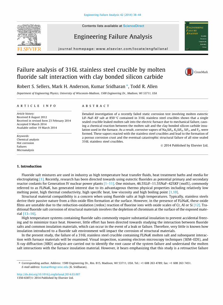
points containing only Fe and O, identified as a-Fe3O3 (hematite). Cross section SEM/EDS maps and point scans of the cruciblewall are shown in Fig. 7 and Table 2 Depletion of iron and chromium along grain boundaries starting at the crucible exteriorand moving radially inwards appears to be the main mode of attack. EDS point scans identify the F, Na, K rich compound exist-ing between the grains as K2NaCrF6. XRD analysis of green substance present on the interior of the corroded crucibles providespositive identification of the presence of K2NaCrF6 in the test system as shown in Fig. 8. The distinct emerald green color andX-ray pattern is consistent with the description of K2NaCrF6 synthesized and characterized by Knox and Mitchell [17].
EDS detection of F, Si, Na and K on the top of the corroded crucible suggests the elements existed in vapor form at thetesting temperature of 850 �C. These elements are abundant in the system in either solid or liquid phases in the form of claybonded SiC and molten FLiNaK salt, respectively. Thus, a reaction occurred between the molten salt and furnace insulationmaterials which lead to the creation of a corrosive vapor. Large quantities of oxygen were detected on the surface crust.

Fig. 5. Point of failure located on the bottom weld.
Fig. 6. SEM micrograph of scale topology.
Table 1EDS elemental distribution of scale topology.
Number EDS chemical composition (at.%)
O Al Si K Cr Fe
1 58.8 2.2 14.0 12.2 0.5 12.22 61.4 2.2 13.0 11.0 0.7 11.43 67.5 – – 21.3 10.6 0.54 63.3 – – 1.0 0.6 33.65 63.6 – – 23.3 11.9 1.1
R.S. Sellers et al. / Engineering Failure Analysis 42 (2014) 38–44 41
However, oxygen was not present in large quantities in the system at testing conditions, so was likely introduced at the con-clusion of the test when the furnace was opened to atmospheric air. Prior to opening the furnace, the temperature was al-lowed to cool to approximately 250 �C. This could be a sufficiently high temperature to allow some surface oxidation. Furtherevidence that oxygen reactions were an isolated surface phenomenon is backed up by the lack of detected oxygen in theSEM/EDS cross sectional images of Fig. 7. Therefore, oxygen was not a contributing factor to the failure of the system.
3.3. Discussion
The test failure was likely initiated by a pinhole leak in a single crucible which allowed FLiNaK to escape and react withthe clay bonded silicon carbide furnace base plate. The reaction taking place at 850 �C created corrosive vapors of SiF3, F2,Na2SiF6, and K2SiF6, evident through the migration of initially solid or liquid phase elements (Si, F, Na, K) to the exteriorof the 316L stainless steel crucibles and to the surface of steel sheathed thermocouples positioned above the crucible set.Investigation of the identity of these destructive vapors is pertinent, although precise identification of the vapors is madedifficult by the complicated nature of the failure and subsequent material interaction.
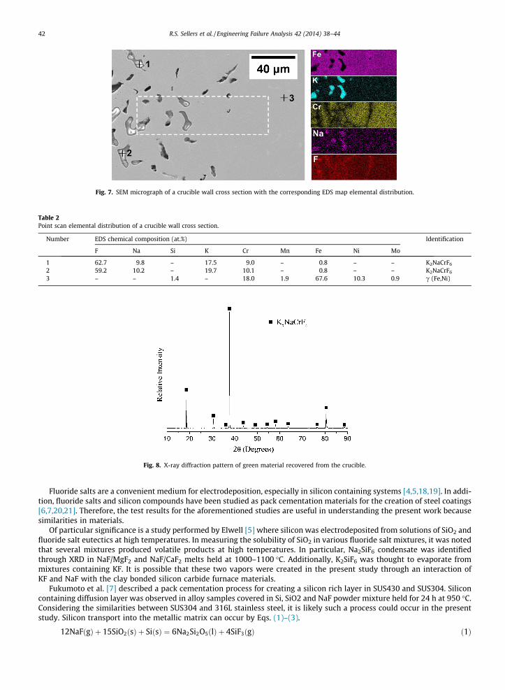
Fig. 7. SEM micrograph of a crucible wall cross section with the corresponding EDS map elemental distribution.
Table 2Point scan elemental distribution of a crucible wall cross section.
Number EDS chemical composition (at.%) Identification
F Na Si K Cr Mn Fe Ni Mo
1 62.7 9.8 – 17.5 9.0 – 0.8 – – K2NaCrF6
2 59.2 10.2 – 19.7 10.1 – 0.8 – – K2NaCrF6
3 – – 1.4 – 18.0 1.9 67.6 10.3 0.9 c (Fe,Ni)
Fig. 8. X-ray diffraction pattern of green material recovered from the crucible.
42 R.S. Sellers et al. / Engineering Failure Analysis 42 (2014) 38–44
Fluoride salts are a convenient medium for electrodeposition, especially in silicon containing systems [4,5,18,19]. In addi-tion, fluoride salts and silicon compounds have been studied as pack cementation materials for the creation of steel coatings[6,7,20,21]. Therefore, the test results for the aforementioned studies are useful in understanding the present work becausesimilarities in materials.
Of particular significance is a study performed by Elwell [5] where silicon was electrodeposited from solutions of SiO2 andfluoride salt eutectics at high temperatures. In measuring the solubility of SiO2 in various fluoride salt mixtures, it was notedthat several mixtures produced volatile products at high temperatures. In particular, Na2SiF6 condensate was identifiedthrough XRD in NaF/MgF2 and NaF/CaF2 melts held at 1000–1100 �C. Additionally, K2SiF6 was thought to evaporate frommixtures containing KF. It is possible that these two vapors were created in the present study through an interaction ofKF and NaF with the clay bonded silicon carbide furnace materials.
Fukumoto et al. [7] described a pack cementation process for creating a silicon rich layer in SUS430 and SUS304. Siliconcontaining diffusion layer was observed in alloy samples covered in Si, SiO2 and NaF powder mixture held for 24 h at 950 �C.Considering the similarities between SUS304 and 316L stainless steel, it is likely such a process could occur in the presentstudy. Silicon transport into the metallic matrix can occur by Eqs. (1)–(3).
12NaFðgÞ þ 15SiO2ðsÞ þ SiðsÞ ¼ 6Na2Si2O5ðlÞ þ 4SiF3ðgÞ ð1Þ

R.S. Sellers et al. / Engineering Failure Analysis 42 (2014) 38–44 43
SiF3ðgÞ þM ¼ SiðsÞ þMF3ðgÞ ð2Þ
SiF3ðgÞ þ 2M ¼ 2SiðsÞ þ 2MF2ðgÞ þ F2ðgÞ ð3Þ
M : Metal elementðFe;Cr;NiÞ
Initially, a silicon fluoride vapor is formed between silicon oxide and sodium fluoride (Eq. (1)) and proceeds to comes incontact with the alloy surface (Eq. (2)). Continuing the reaction, metal fluoride compounds along with fluorine gas is formedand solid silicon is liberated at the alloy surface (Eq. (3)) and is able to diffuse into the steel, leading to the formation of the Sirich layer. In the Fukumoto paper [7], the chemical reactions were explained using thermodynamic calculations as well asXRD identification of the 6Na2Si2O5.
A similar process likely occurred in the present study due to the abundant supply of NaF, SiO2 and Si contained in the boxfurnace system at high temperatures. Eq. (4) is hypothesized as an explanation for the formation of K2NaCrF6 taking intoaccount the process described by Fukumoto along with the K2SiF6/Na2SiF6 vapors shown to have been created in similarexperimental systems. Such a reaction would also provide additional silicon fluoride vapor near the alloy surface to continuethe fluorination process described by Fukumoto in Eqs. (2) and (3).
2Na2SiF6ðgÞ þ 4K2SiF6ðgÞ þ 4CrðsÞ þ 3F2ðgÞ ¼ 4K2NaCrF6ðsÞ þ 6SiF3ðgÞ ð4Þ
The formation of metallic fluorine compounds described by Fukumoto is consistent with the attack seen in the EDS crosssectional image of Fig. 7, where depletion of chromium and iron can be observed. Previous work has shown that chromiumand iron are the most thermodynamically favored alloying constituents for fluorine attack in a 316L stainless steel system[14]. In addition, it has been shown that Iron (II) Fluoride can sublimate at temperatures as low as 690 �C [22]. Such a sub-limation process explains the distinct iron voids in Fig. 7 as well as the porous structure of the corrosion crust whereby Iron(II) fluorine vapor pockets would exert pressure on surrounding material, causing expansion and eventual release of FeF2
vapor. Combining the Fukumoto silicon fluoride diffusion theory with the sublimation of FeF2 and the synergistic effectsof the K2SiF6/Na2SiF6 vapors over hundreds of hours, it can be seen how this processes would create a porous corrosion crustthat compromises the structural integrity of the stainless steel tube.
4. Conclusion
Visual inspection, SEM/EDS examination, and XRD analysis were carried out to investigate the failure of a 316L stainlesssteel molten fluoride salt containing system in a high temperature box furnace held at 850 �C for 1000 h. It was found thatFLiNaK molten salt escaped through a pinhole leak in a single static test crucible and reacted with the clay bonded siliconcarbide base plate installed in the box furnace. Vapors of SiF3, Na2SiF6, and K2SiF6 were formed and subsequently attackedthe 316L system through a fluorination process described by Fukumoto and Elwell. It is hypothesized that this process con-tributed to the creation of K2NaCrF6 identified by XRD as well as the sublimation of FeF2. These combined effects extendedover hundreds of hours created a porous corrosion crust which caused the remaining static test crucibles to become struc-turally unsound. The compromised crucibles released additional FLiNaK contents which continued the vapor corrosionprocess.
5. Recommendations
Considering the large quantity of insulation typically found in systems containing heated molten salt and the destructivenature of the resulting corrosive vapors, some recommendations to further understand reaction mechanisms and minimizetest failures are as follows:
1. Construct a stainless steel boat or perform the test in a retort furnace so leaked salt will come into contact with metalliccomponents only. Such interactions are fairly well understood and vapors will not be created.
2. Minimize internal pressurization of corrosion testing vessels through hot finish welding, vacuum sealing or atmosphericvented apparatus.
3. Verify weld integrity through X-ray analysis.4. A campaign of theoretical, electrochemical and experiential studies is required to truly understand molten fluoride salt
insulation interaction. The work presented here is hindered by the need to retroactively construct a narrative using quan-titative clues as opposed to a narrowly defined bottom-up approach.
Acknowledgements
The authors are very grateful to the Department of Energy of the United States of America for funding support underGrant No. DOE-FC07-05ID14675 and DOE-FC07-07ID14826. This research utilized NSF-supported shared facilities at theUniversity of Wisconsin.

44 R.S. Sellers et al. / Engineering Failure Analysis 42 (2014) 38–44
References
[1] Holcomb DE, Cetiner SM. An overview of liquid-fluoride-salt heat transport systems. ORNL/TM-2010/156; 2010.[2] United States Department of Energy. A technology roadmap for generation IV nuclear energy systems. GIF-002-00; 2002.[3] Flanagan GF, Holcomb DE, Cetiner SM. FHR generic design criteria. ORNL/TM-2012/226; 2012.[4] Stern KH, McCollum ME. Electrodeposition of silicon from molten salts. Thin Solid Films 1985;124:129–34.[5] Elwell D. Electrowinning of silicon from solutions of silica in alkali metal fluoride/alkaline earth fluoride eutectics. Solar Energy Mater 1981;5:205–10.[6] Kim MT, Jung JS. Codeposition of Al and Si onto a low carbon steel using silicon dioxide and aluminum and its hot temperature oxidation properties.
Surf Coat Technol 2002;161:218–23.[7] Fukumoto M, Tachikawame C, Matsuzaka Y, Hara M. Formation of Si diffusion layer on stainless steels and their high temperature corrosion resistance
in molten salt. Corros Sci 2012;56:105–13.[8] Ambrosek J, Anderson M, Sridharan K, Allen T. Current status of knowledge of the fluoride salt (FLiNaK) heat transfer. Nucl Technol 2009;165:166–73.[9] Ozeryanaya IN. Corrosion of metals by molten salts in heat-treatment processes. Met Sci Heat Treat 1985;3:184–8.
[10] Williams DF. Assessment of candidate molten salt coolants for the NGNP/NHI heat-transfer loop. ORNL/TM-2006/69; 2006.[11] Williams D, Toth L, Clarno K. Assessment of candidate molten salt coolants for the advanced high-temperature reactor (AHTR). ORNL/TM-2006/12;
2006.[12] Williams DF, Toth LM. Chemical considerations for the selection of the coolant for the advanced high-temperature reactor. ORNL/GEN4/LTR-05-011;
2005.[13] Olson LC. Materials corrosion in molten LiF-NaF-KF salt [Ph.D. dissertation]. University of Wisconsin-Madison; 2009.[14] Olson LC, Ambrosek JW, Sridharan K, Anderson MH, Allen TR. Materials corrosion in molten LiF–NaF–KF salt. J. Fluorine Chem. 2009;130:67–73.[15] Olson LC, Ambrosek JW, Cao G, Sridharan K, Anderson MH, Allen TR. Molten salts for nuclear cogeneration. Adv Mater Sci Environ Nucl Technol
2010;222:145–56.[16] Cheng WJ, Sellers RS, Anderson MH, Sridharan K, Wang C, Allen TR. Zirconium effect on the corrosion behavior of 316L stainless steel alloy and
Hastelloy-N superalloy in molten fluoride salt. Nucl Technol 2013;183:248–59.[17] Knox K, Mitchell DW. The preparation and structure of K2NaCrF6, K2NaFeF6 and K2NaGaF6. J Inorg Nucl Chem 1961;21:253–8.[18] Bieber AL, Massot L, Gibilaro M, Cassayre L, Chamelot P, Taxil P. Fluoroacidity evaluation in molten salts. Electrochim Acta 2011;56:5022–7.[19] Bieber AL, Massot L, Gibilaro M, Cassayre L, Taxil P, Chamelot P. Silicon electrodeposition in molten fluorides. Electrochim Acta 2012;62:282–9.[20] Hsu H, Tsai W. High temperature corrosion behavior of siliconized 310 stainless steel. Mater Chem Phys 2000;64:147–55.[21] Tatemoto K, Ono Y, Suzuki RO. Silicide coating on refractory metals in molten salt. J Phys Chem Solids 2005;66:526–9.[22] Kent R, Margrave JL. Mass spectometric at high temperatures. VIII. The sublimation pressure of iron(II) fluoride. J Am Chem Soc 1965;87:4754–6.