THE WIRELE WORLD - americanradiohistory.com · WIRELE THE S S WORLD In Yokohama Harbour ... l

t
NAB CONVENTION ISSUE
OMMU íßi ì CAT I ON t
1 ENGINEERING
www.americanradiohistory.com
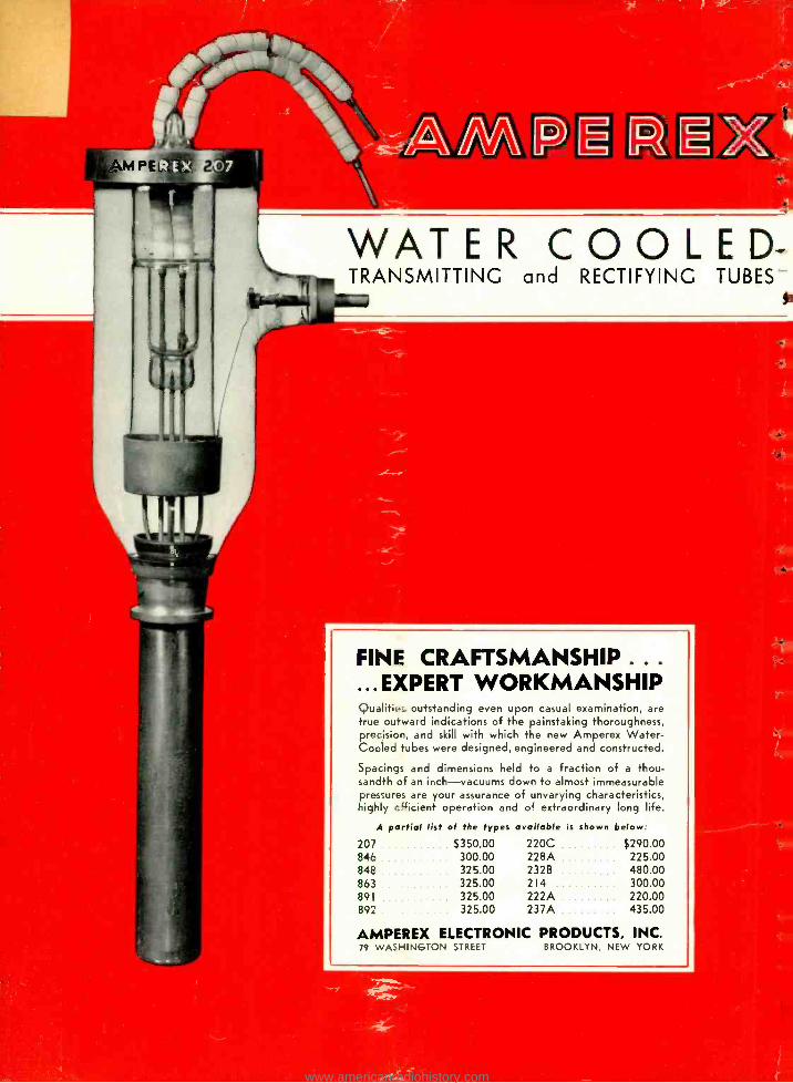
WATER COOLED- TRANSMITTING and RECTIFYING TUBES-
FINE CRAFTSMANSHIP .. .
...EXPERT WORKMANSHIP Qualiti.: outstanding even upon casual examination, are true outward indications of the painstaking thoroughness, precision, and skill with which the new Amperex Water - Cooled tubes were designed, engineered and constructed.
Spacings and dimensions held to a fraction of a thou- sandth of an inch -vacuums down to almost immeasurable pressures are your assurance of unvarying characteristics, highly cgicient operation and of extraordinary long life.
A partial list of the types available is shown below:
207 $350.00 220C $290.00 846 300.00 228A 225.00 848 325.00 232B 480.00 863 325.00 214 300.00 891 325.00 222A 220.00 892 325.00 237A 435.00
AMPEREX ELECTRONIC PRODUCTS, INC. 79 WASHINGTON STREET BROOKLYN, NEW YORK
www.americanradiohistory.com
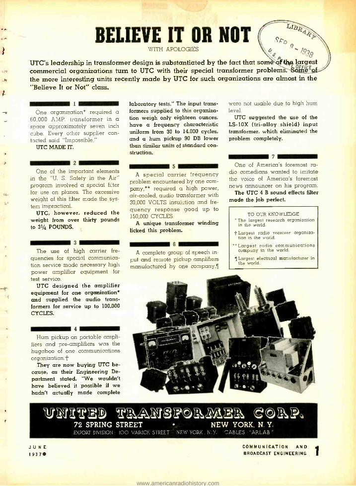
BELIEVE IT OR NOT WITH APOLOGIES
19 ?8 UTC's leadership in transformer design is substantiated by the fact that som Mr. largest commercial organizations turn to UTC with their special transformer problems -SoÇ E
the more interesting units recently made by UTC for such organizations are almost in the "Believe It or Not" class.
1
One organization* required a 60,000 AMP. transformer in a space approximately seven inch cube. Every other supplier con- tacted said "Impossible."
UTC MADE IT.
2
One of the important elements in the "U. S. Safety in the Air" program involved a special filter for use on planes. The excessive weight of this filter made the sys- tem impractical.
UTC, however, reduced the weight from over thirty pounds to 31/4 POUNDS.
3
The use of high carrier fre- quencies for special communica- tion service made necessary high power amplifier equipment for test service.
UTC designed the amplifier equipment for one organization* and supplied the audio trans- formers for service up to 100,000
CYCLES.
4
Hum pickup on portable ampli- fiers and pre -amplifiers was the bugaboo of one communications organization.t
They are now buying UTC be- cause, as their Engineering De- partment stated, "We wouldn't have believed it possible if we hadn't actually made complete
laboratory tests." The input trans- formers supplied to this organiza- tion weigh only eighteen ounces, have a frequency characteristic uniform from 30 to 14,000 cycles, and a hum pickup 90 DB lower than similar units of standard con- struction.
5
A special carrier frequency problem encountered by one com- pany,** required a high power, air- cooled, audio transformer with 30,000 VOLTS insulation and fre- quency response good up to 150,000 CYCLES.
A unique transformer winding licked this problem.
6
A complete group of speech in- put and remote pickup amplifiers manufactured by one company,
were not usable due to high hum level.
UTC suggested the use of the LS-10X (tri -alloy shield) input transformer, which eliminated the problem completely.
7
One of America's foremost ra- dio comedians wanted to imitate the voice of America's foremost news announcer on his program.
The UTC 4 B sound effects filter made the job perfect.
TO OUR KNOWLEDGE The largest research organization in the world.
I. Largest radio receiver organiza- tion in the world.
" Largest radio communications company in the world.
Largest electrical manufacturer in the world.
1I0222D tk3J,24tg0aaNA2a, 72 SPRING STREET NEW YORK, N. Y. EXPORT DIVISION: 100 VAR[CK STREET NEW YORK. N.Y. CABLES :'BARLAB
JUNE I 937
COMMUNICATION AND BROADCAST ENGINEERING
www.americanradiohistory.com
COMMU
RAY D. RETTENMEYER Editor
MCAT ON & ,ENGYNE Rfl\\
BR,OA
G Registered U. S. Paten Office
Member of Audit Bureau of Circulations
DCAST
F. WALEN Associate Editor
VOLUME 4 JUNE, 1937 NUMBER 6
CONTENTS Cover Illustration: The new Coaxial Antenna which engi-
neers have demonstrated with ultra - high - frequency transmitters. It may be described as a vertical dipole half -wave radiator. Courtesy Western Electric Com- pany.
P qe
Editorial 4
Frontispiece: The Radio Industry in Photomural 6
NAB Convention 7
Mixer Circuits, Part I By Albert Preisman 9
Lorenz Instrument -Landing System as Demonstrated at Indianapolis 12
The Low -Power Transmitters By John P. Taylor 14
The RCA 887, 888 18
Television Studio Considerations, Part III By W. C. Eddy 20
An A -F and R -F Wiring Device By Magnus Bjorndal 24
Veteran Wireless Operators Association News 26
The Market Place 30
Index of Advertisers 40
Copyright 1937 -Bryan Davis Publishing Co., Inc.
Broadcast Transmission
Recording
Sound Projection
Television
Facsimile
Aeronautical Radio
Police Radio
Marine Radio
Carrier Transmission
Beam Transmission
Radio Telegraphy
Radio Telephony
BRYAN S. DAVIS President
JAMES A. WALKER Secretary
Published Monthly by the
BRYAN DAVIS PUBLISHING CO., INC. 19 East 47th Street
New York City New York Telephone: PLaza 3 -0483
Chicago Office -608 S. Dearborn St. -C. O. Stimpson, Mgr. Telephone: Wabash 1903.
PAUL S. WEIL Advertising Manager
A. B. CARLSEN Circulation Mnage-
Cleveland Office -10515 Wilbur Ave.-J. C. Munn, Mgr. Telephone: Republic 0905 -J.
Wellington, New Zealand -Te Aro Book Depot. Melbourne, Australia -McGill's Agency.
Entered as second class natter October 17. 1934. at the Post Office a New York, N. Y., under the act of March 3, 1879. Yearly subscription rate: $2.00 in the United States and Canada. $3.00 in foreign countries.
Single copies: twenty -fire cents in United States and Canada. thirtfive cents in foreign countries.
2 JUNE 1937
COMMUNICATION AND BROADCAST ENGINEERING
.4
r
www.americanradiohistory.com
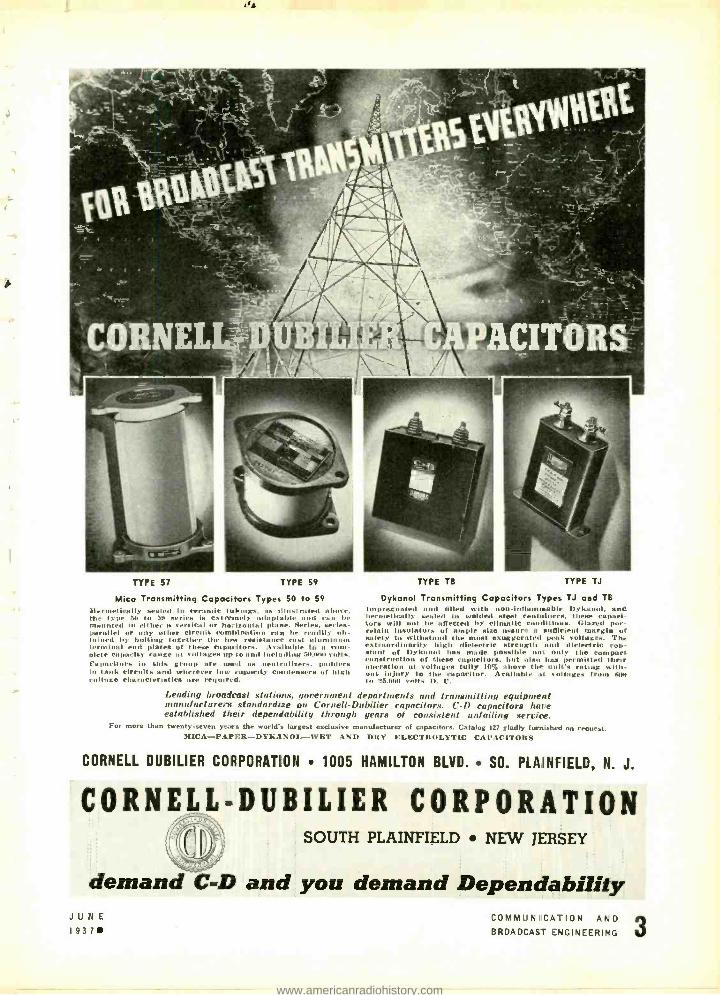
TYPE 57 TYPE 59
Mica Transmitting Capacitors Types 50 to 59
Hermetically settled In ceramic I uhi n gs, as illustrated above. the type 611 lo 59 series is extremely adaptable and can be mounted in either u vertical or horizontal plane. Series, series - parallel or any other circuit combination ran be readily ob- tuined liy bolting together the low resistance mist aluminum terminal end plies of these capacitors. Asallnble In a com- plete capacity lty range at S iiltages up tomtit I IIrl titling 611,00 volts. Fu pacitors in this group are used as neutralizers. amblers in hulk circuits und wherever low rapacity rat densers of high i atttl ge characteristics are required.
TYPE TB TYPE TJ
Dykanol Transmitting Capacitors Types TJ and TB impregnated and tilled with nun -in lia mina lile Dy kunol, and hermetically sealed in welded steel container.+, these capaci. tors will not be affected by climatic conditions. Glared por- celain Insulators of ample size assure a sufficient margin of safety to withstand the most exaggerated peak voltages. The extraordinarily high dielectric strength and dielectric con stunt of Dykanol has made possible not only the compact construction of these capacitors, but also has permitted their operation at voltages fully 10% above the unit's rating nIth- nnt injury to the capacitor. Available at soilages from /NNI to 25.011 volts IL ('.
Leading broadcast stations. ,government departments and transmitting equipment manufacturers standardize on ('ornell- Dubilier capacitors. C -D capacitors have established their dependability through years of consistent unfailing service.
For more than twenty -seven years the world's largest exclusive manufacturer of capacitors. Catalog 127 gladly furnished on request. MICA -PAPER- DYKANOL --WET AND DRY ELECTROLYTIC CAPACITORS
CORNELL DUBILIER CORPORATION 1005 HAMILTON BLVD. SO. PLAINFIELD, N. J.
CORNELL-DUBILIER CORPORATION SOUTH PLAINFIELD NEW JERSEY
demand C -D and you demand Dependability JUNE 1937
CCMM'UNICA -ION AND BROADCAST = NGINEERING 3
www.americanradiohistory.com
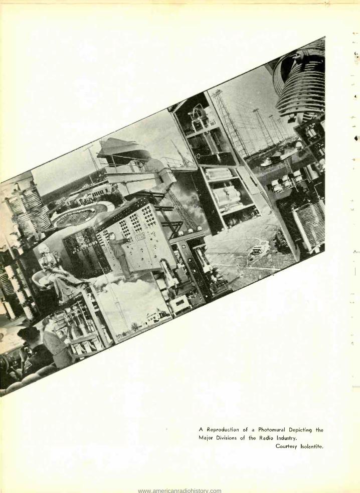
A Reproduction of a Photomural Depicting the Major Divisions of the Radio Industry.
Courtesy Isolantite.
4
www.americanradiohistory.com
CoIVI vii
EN
ON & BROADCAST GIN 1EI1110
FOR JUNE, 1937
!AAB CONVENTION To Be Held June 20 To June 23 .t1 The Sherman Hotel In Chicago
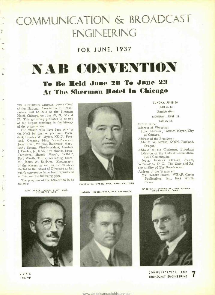
THE FIFTEENTH ANNUAL CONVENTION
of the National Association of Broad- casters will be held at the Sherman Hotel, Chicago, on June 20, 21, 22 and 23. This gath. ring promises to be one of the larges'. meetings in the history of the organi cation.
The office; s who have been serving the NAB fo.- the last year are: Presi- dent, Charles W. Myers, KOIN, Port- land, Oregon; First Vice -President, John Elmer, WCBM, Baltimore, Mary- land; Second Vice -President, Gardner J. Cowles, Jr., KSO, Des Moines, Iowa; Treasurer, Harold Hough, WBAP, Fort Worth, Texas; Managing Direc- tor, James W. Baldwin. Photographs of the officers as well as the members elected to the Board of Directors at last year's convention have been reproduced on this and the following page.
The program of the convention is as follows:
JOHN ELMER. WCBM, FIRST VICE - PRESIDENT, NAB.
JUNE 1937
CHARLES W. MYERS. KOIN. PRESIDENT. NAB.
HAROLD HOUGH. WBAP, NAB TREASUR_R.
SUNDAY. JUNE 20
10:00 A. M.
Rcgi,tration
MONDAY. JUNE 21
9:30 A. M.
Call to Order Address of Welcome:
HON. EDWARD J. KELLY, Mayor, City of Chicago.
Address of the President: MR. C. W. MYERS, KOIN, Portland,
Oregon. Address of the Chairman, Broadcast
Division of the Federal Communica- tions Commission:
JUDGE EUGENE OCTAVE SYKES,
Washington, D. C. The Duty and Re- sponsibility of The Broadcaster. Address of the Treasurer :
MR. HAROLD HOUGH, WBAP, Carter Publications, Inc., Fort Worth, Texas.
GARDNER I. COWLES. JR., KSO, SECOND VICE -PRESIDENT, NAB.
COMMUNICATION AND J BROADCAST ENGINEERING I
www.americanradiohistory.com
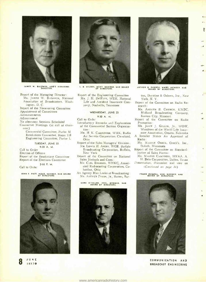
JAMES W. BALDWIN. NAB'S MANAGING DIRECTOR.
Report of the Managing Director: MR. JAMES W. BALDWIN, National Association of Broadcasters, Wash-
ington, D. C. Report of the Nominating Committee Appointment of Committees Announcements Adjournment No afternoon Sessions Scheduled Committee Meetings (at call of chair-
man) Commercial Committee, Parlor M Resolutions Committee, Room 118 Engineering Committee, Parlor L
TUESDAY, JUNE 22
9:30 A. M. Call to Order Election of Officers Report of the Resolutions Committee Report of the Elections Committee
2:00 P. M. Call to Order
JOHN F. PATT. WEAR. MEMBER. NAB BOARD OF DIRECTORS
8 JUNE 19370
L. B. WILSON, WCK Y. MEMBER, NAB BOARD OF DIRECTORS.
Report of the Engineering Committee MR. J. H. DEWITT, WSM, National
Life and Accident Insurance Com- pany, Nashville, Tennessee
WEDNESDAY, JUNE 23
9:30 A. M. Call to Order Introductory Remarks and Explanation
of the Commercial Section Organiza- tion :
MR. H. K. CARPENTER, WHK, Radio Air Service Corporation, Cleveland, Ohio
Report of the Sales Managers' Division : MR. Lewis H. AVERY, WGR, Buffalo
Broadcasting Corporation, Buffalo, New York
Report of the Committee on National Sales Methods and Costs: MR. CARL EVERSON, WHKC, Associ-
ated Radiocasting Corporation, Co- lumbus, Ohio
An Agency Man Looks at Broadcasting :
Ma. ARTHUR PRYOR, JR., Batten, Bar-
GENE O'FALLON. KEEL. MEMBER. NAB BOARD OF DIRECTORS.
ARTHUR B. CHURCH. WMBC. MEMBER. NAB BOARD OF DIRECTORS.
ton, Durstine & Osborn, Inc., New York, N. Y.
Report of the Committee on Radio Re- search :
MR. ARTHUR B. CHURCH, KM BC, Midland Broadcasting Company, Kansas City, Missouri
Report of the Committee on Radio Promotion :
MR. JOHN J. GILLIN, JR., WOW, Woodmen of the World Life Insur- ance Association, Omaha, Nebraska
A Retailer Makes An Appraisal of Radio: MR. MARLIN ORECK, Oreck's, Inc.,
Duluth, Minnesota Report of the Committee on Standard-
ization of Sales Forms :
MR. MARTIN CAMPBELL, WFAA, A. H. Belo Corporation, Dallas, Texas
Presentation, discussion and vote on (Continued on page 34)
FRANK RUSSELL. WRC. MEMBER. NAB BOARD OF DIRECTORS.
COMMUNICATION AND BROADCAST ENGINEERING
.4
.r-
-4
vt
T
www.americanradiohistory.com
e
MIXER CIRCI?ITS P4\ RT I
By ALBERT PREISMAN
Head of The Department of Audio -Frequency Engineering
RCA INSTITUTES, INC.
I. INTRODUCTION
A MIXER is a network interposed be- tween several signal sources and a load for the purpose of enabling each signal source and the load to see its image im- pedance when looking into the terminals of the mixer to which it is connected. In power work the several generators are usually connected in parallel to the corn- mon load since most power systems are constant -potential systems. Such direct parallel connection is feasible because only one frequency (usually 60 cycles) is involved so that such matters as re- flection losses and uniform frequency response are of no consideration. and impedances are not matched but instead are arranged so that the load impedance is very high compared to that of the generators in order to have maximum efficiency of power transfer rather than maximum power transfer itself.
It is precisely the above considera- tions which are unimportant in power work, that are very important in com- munication work, and hence we require a mixer network to be interposed be- tween the generators and the load for the purpose of impedance matching. While a mixer can hardly be said to cause maximum power transfer, it can, by its impedance- matching properties, cause the transmission of power to be uniform over a wide band of frequencies just as in simple one -generator, one- load circuits.
Since (1) communication circuits are not of the constant -potential type but rather of the constant -impedance type, (2) the several generators may gen- erate voltages of different frequencies and phase with respect to one another, and (3) usually are of low efficiency so that any one generator pumps negligible energy back into the others, they may be connected either in series, parallel, or series -parallel.
Thus, the generators or sources may be several microphones picking up, for instance, the sounds from the same in- struments or different instruments of an orchestra, or they may be several phono- graph pickups or photoelectric -cell pick- ups or combinations of these various types, all feeding the common load, which is practically always the input
JUNE I937
transformer of an amplifier. In any of these cases, it will be evident that one source or generator will not appreciably tend to make the others operate as motors since they are transducers of very low efficiency and in some cases, such as, the output of microphone pre- amplifiers, irreversible in their action. Before going into the design of mixer circuits themselves we may note that the sources may have very weak out- puts, in which case the process is known as "low -level mixing," or the sources may be relatively strong in output, in which case we have "high -level mix- ing." An example of the former is the case where ribbon microphones are mixed directly, in which case their out- put level is about minus 75 db each and the mixing is therefore at a low level. Should these same microphones, how- ever, be connected to preamplifiers and the outputs of the latter (about minus 30 db each) mixed, we have high -level mixing. Usually high -level mixing is employed because of the higher ratio of signal to noise.
II. SERIES MIXER
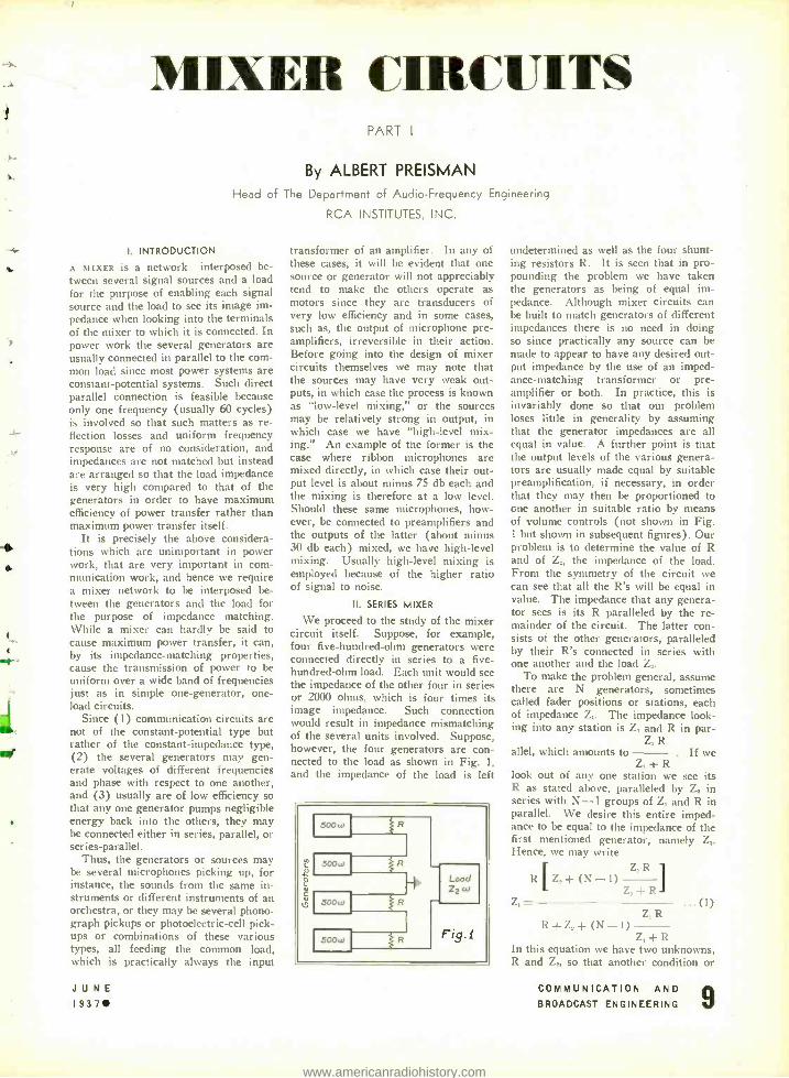
We proceed to the study of the mixer circuit itself. Suppose, for example, four five- hundred -ohm generators were connected directly in series to a five - hundred -ohm load. Each unit would see the impedance of the other four in series or 2000 ohms. which is four times its image impedance. Such connection would result in impedance mismatching of the several units involved. Suppose, however, the four generators are con- nected to the load as shown in Fig. 1, and the impedance of the load is left
undetermined as well as the four shunt- ing resistors R. It is seen that in pro- pounding the problem we have taken the generators as being of equal im- pedance. Although mixer circuits can be built to match generators of different impedances there is no need in doing so since practically any source can be made to appear to have any desired out- put impedance by the use of an imped- ance- matching transformer or pre- amplifier or both. In practice, this is invariably done so that our problem loses little in generality by assuming that the generator impedances are all equal in value. A further point is that the output levels of the various genera- tors are usually made equal by suitable preamplification. if necessary, in order that they may then be proportioned to one another in suitable ratio by means of volume controls (not shown in Fig. 1 but shown in subsequent figures). Our problem is to determine the value of R and of Z,, the impedance of the load. From the symmetry of the circuit we can see that all the R's will be equal in value. The impedance that any genera- tor sees is its R paralleled by the re- mainder of the circuit. The latter con- sists of the other generators, paralleled by their R's connected in series with one another and the load Z,.
To make the problem general, assume there are N generators, sometimes called fader positions or stations, each of impedance Z,. The impedance look- ing into any station is Z, and R in par -
Z, R allel, which amounts to . If we
Z, +R look out of any one station we see its R as stated above, paralleled by Z, in series with N -1 groups of Z, and R in parallel. We desire this entire imped- ance to be equal to the impedance of the first mentioned generator, namely Z,. Hence, we may write
Z,R 1 R[ Z, +(N -1)
Z, +R Z, = ...(I)
Z, R R +Z, +(N 1)
Z, +R In this equation we have two unknowns, R and Z. so that another condition or
COMMUNICATION AND BROADCAST ENGINEERING 9
www.americanradiohistory.com
equation may be imposed. This will of course be that the load Z, looking back into the sources will see its image im- pedance Z_. This means that
Z, R Z, = N
Z, -- R
Solving equations (1) and (2) simul- taneously, we obtain
(2)
R = Z, ( N
J, N -1 and (3)
¡ N' Z2= Z, 1
2N -1) Here we start with Z, and N known,
and solve for Z, and R. However, if we were to start with Z, and N known, we could solve for Z, and R. Thus
L
2N-1 Z, Z,
1 N' 2N-1
R= Z,r LN (N-1)
1
(4)
These are the basic equations for a series mixer.
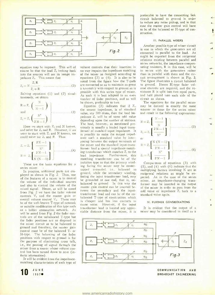
In practice, additional parts are em- ployed as shown in Fig. 2. Thus, one of the features of a mixer is to control the volume of the individual sources and also to control the volume of the mixed signal. Hence, as will be noted from Fig. 2 we have the fader volume controls V, and the master gain or overall volume control V,. These may be of the well -known T -type of network or suitable modification of this type such as a ladder attenuation network. As will be noted from Fig. 2 the fader con- trols are of the unbalanced T -type but the fader positions are so disposed in the mixer circuit as to be balanced to ground and therefore, the master gain control must be of the balanced T- or H -type. The balancing of the fader positions with respect to ground is for the purpose of eliminating cross talk, i.e., the passing of signal through the mixer from a source whose- volume con- trol has been turned down to zero (in- finite attenuation).
It will be evident from the impedance - matching characteristics of such type of
10 JUNE I937
volume controls that their insertion in no way impairs the impedance matching of the mixer as designed according to equations (3) or (4). It is also to be noted from the figure how the T -pads are connected so as to maintain as great a symmetry with respect to ground as is possible with this series type of mixer. As such it is best adapted to an even number of fader positions, and as will he shown, preferably to two.
Equation (3) indicates that if Z,, the source impedance, is of standard value, say 500 ohms, then the load im- pedance Z, will be of some odd value depending upon the number of stations. The load, however, as mentioned pre- viously is usually a loaded input trans- former of standard input impedance. It is possible to make the output imped- ance such a standard value by inter- posing between the output terminals of the mixer and the standard input- trans- former load a special impedance- match- ing transformer which matches Z, to the load impedance. Furthermore, this matching transformer can be of the isolation type so that the primary wind- ing facing the mixer may be center - tapped grounded, i.e., balanced to ground, while the secondary winding, facing the input transformer load, may be grounded at one end, that is, un- balanced to ground. In this way the master gain control can be inserted be- tween the secondary and the input - transformer load and can be of the un- balanced T -type of construction which is cheaper and has less contacts to cause noise. However, if the input transformer load is located any appre- ciable distance from the mixer, it is
preferable to have the connecting link circuit balanced to ground in order to reduce any noise pickup, and in that case the master gain control will have to be of the balanced or H -type of con- struction.
III. PARALLEL MIXERS
Another possible type of mixer circuit is one in which the generators are all connected in parallel to the load. As might be expected from the reciprocal relations existing between parallel and series networks, the impedance- compen- sating resistors, R in this case, will be in series with the generators rather than in parallel with them and the cir- cuit arrangement is shown in Fig. 3. The figure illustrates a circuit balanced to ground. Hence H -type fader vol- ume controls are required, and the re- sistance R is split into two equal parts, and half placed into each side of the circuit as shown.
The equations for the parallel mixer may be derived in exactly the same manner as those for the series mixer and result in the following expressions:
N-1 7 R Z,
N
Z, = z, Ì
N' or
R=7_, rN (N-1)1 1
2N-1 N'
Z, = Z, r L 2N-1 I J
(S)
(6)
Comparisons of equations (3) with (5), and (4) with (6) indicate that the multiplying factors involving N are in reciprocal relations as might be ex- pected. As in the case of the series mixer, an impedance -changing trans- former may be inserted in the output of the mixer in order to pass from the odd value of impedance Z. back to a standard value again.
IV. FURTHER CONSIDERATIONS
It is evident that the output of a mixer may be considered in itself as a
z,
z,
z,
R/2
, ramaa 2 ,
Zz
Fig.3
COMMUNICATION AND BROADCAST ENGINEERING
4-
.4
M.
www.americanradiohistory.com
-
r`
source of signal. Hence several mixers may in turn be mixed to produce what may be termed an overall mixer. Thus, suppose in a large theatre there are five footlight microphones, three micro- phones located in the orchestra pit and four microphones located in the wings of the stage. The microphones in each group may be mixed in a series or par- allel arrangement and then the groups may be mixed in a parallel or series ar- rangement, and the entire output con- trolled by what may be termed a "master master" gain control. Of course, the output of each group will have to be transformed into a common value of impedance before it is mixed with the others in the overall mixer.
By such means it is possible to pick up sound from any part of the stage, blend it suitably with the signals picked up from the orchestra, whose micro- phones blended chorus, blended desired groups sound- reenforcing system. The same principle may be employed in mixing several sources of the same type. The result is that from the series and parallel mixers previously evolved there can be evolved two new combinations, namely, series -parallel and parallel- series mixers.
V. SERIES -PARALLEL AND PARALLEL - SERIES MIXERS
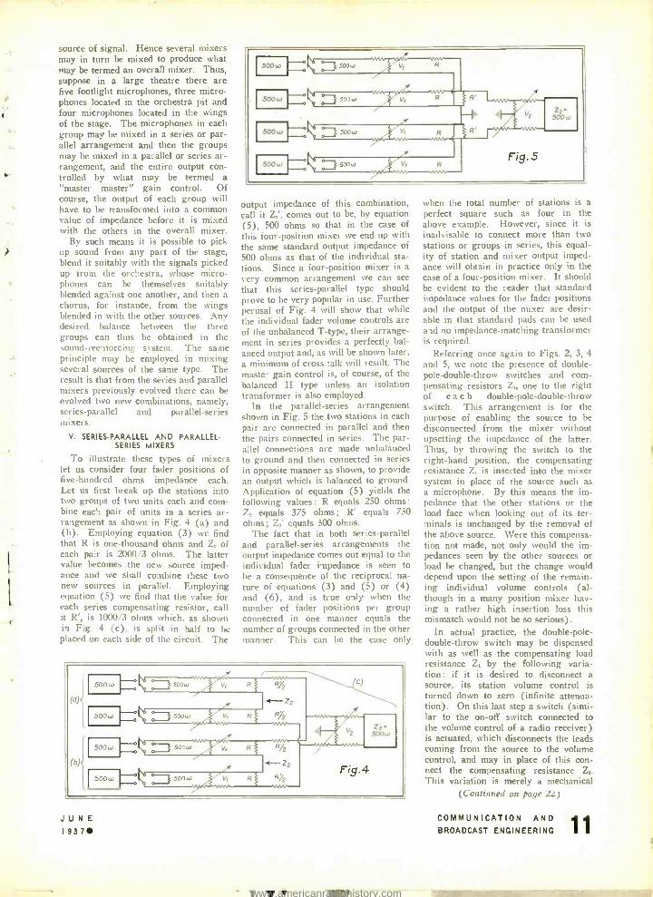
To illustrate these types of mixers let us consider four fader positions of five -hundred ohms impedance each. Let us first break up the stations into two groups of two units each and com- bine each pair of units in a series ar- rangement as shown in Fig. 4 (a) and (b). Employing equation (3) we find that R is one -thousand ohms and Z, of each pair is 2000/3 ohms. The latter value becomes the new source imped- ance and we shall combine these two new sources in parallel. Employing equation (5) we find that the value for each series compensating resistor, call it R', is 1000/3 ohms which, as shown in Fig. 4 (c). is split in half to be placed on each side of the circuit. The
can be themselves suitably against one another, and then a for instance, from the wings in with the other sources. Any balance between the three
can thus be obtained in the
I500u1 500,0
I 500w
500 W f
f
4 Fig. 5
Z2- 500w
output impedance of this combination, call it Z,', comes out to he, by equation (5), 500 ohms so that in the case of this four -position mixer we end up with the same standard output impedance of 500 ohms as that of the individual sta- tions. Since a four -position mixer is a very common arrangement we can see that this series -parallel type should prove to be very popular in use. Further perusal of Fig. 4 will show that while the individual fader volume controls are of the unbalanced T -type, their arrange- ment in series provides a perfectly bal- anced output and, as will be shown later, a minimum of cross talk will result. The master gain control is, of course, of the balanced H type unless an isolation transformer is also employed.
In the parallel- series arrangement shown in Fig. 5 the two stations in each pair are connected in parallel and then the pairs connected in series. The par - allel connections are made unbalanced to ground and then connected in series in opposite manner as shown, to provide an output which is balanced to ground. Application of equation (5) yields the following values : R equals 250 ohms: Z, equals 375 ohms; R' equals 750 ohms; Z,' equals 500 ohms.
The fact that in both series -parallel and parallel- series arrangements the output impedance comes out equal to the individual fader impedance is seen to be a consequence of the reciprocal na- ture of equations (3) and (5) or (4) and (6), and is true only when the number of fader positions per group connected in one manner equals the number of groups connected in the other manner. This can be the case only
JUNE 1937
when the total number of stations is a perfect square such as four in the above example. However, since it is inadvisable to connect more than two stations or groups in series, this equal- ity of station and mixer output imped- ance will obtain in practice only in the case of a four -position mixer. It should be evident to the reader that standard impedance values for the fader positions and the output of the mixer are desir- able in that standard pads can be used and no impedance -matching transformer is required.
Referring once again to Figs. 2, 3, 4 and 5, we note the presence of double - pole- double -throw switches and com- pensating resistors Z,, one to the right of each double- pole -double -throw switch. This arrangement is for the purpose of enabling the source to be disconnected from the mixer without upsetting the impedance of the latter. Thus, by throwing the switch to the right -hand position, the compensating resistance Z, is inserted into the mixer system in place of the source such as a microphone. By this means the im- pedance that the other stations or the load face when looking out of its ter- minals is unchanged by the removal of the above source. Were this compensa- tion not made, not only would the im- pedances seen by the other sources or load be changed, but the change would depend upon the setting of the remain- ing individual volume controls (al- though in a many position mixer hav- ing a rather high insertion loss this mismatch would not be so serious).
In actual practice, the double -pole- double -throw switch may be dispensed with as well as the compensating load resistance Z, by the following varia- tion : if it is desired to disconnect a source, its station volume control is turned down to zero (infinite attenua- tion). On this last step a switch (simi- lar to the on -off switch connected to the volume control of a radio receiver) is actuated, which disconnects the leads coming from the source to the volume control, and may in place of this con- nect the compensating resistance Z,. This variation is merely a mechanical
(Continued on page 22)
COMMUNICATION AND BROADCAST ENGINEERING
www.americanradiohistory.com

THE Low -POWER TRANSMITTERS
By JOHN P. TAYLOR
xo TYPE of broadcast equipment com- mands more widespread attention than do the transmitters designed for low - power stations -low power, in this in- stance, meaning 250 watts or less. A large majority of the presently- estab- lished stations fall in this category - also nearly all of the recently -granted permits. Of some thirty -five "new sta- tion" applications approved during the past year, all but a few were for 250 watts or less. Moreover, the Commis- sion's tentative plans -which provide "from 50 to 500" new stations in the 1500 to 1600 kc band -indicate the probability of a considerable number of additional stations of this classification.
There was a time when only a small fraction of low -power licensees made use of the so- called "standard" or fac-
FIG. I. FRONT VIEW OF THE 100 -G 250 -G TRANSMITTER.
tory- manufactured transmitters. The revenues of these stations simply did not permit it. Today this picture is
14 JUNE 19370
FIG. 4. FRONT VIEW OF THE 100 -H /250 -D TRANS- MITTER. NOTE THAT PANEL DOOR IS OPEN SHOWING LOCATION OF TUNING CONTROLS AND INDIVIDUAL PLATE -CUR- RENT METERS ON THE
RECESSED SUB -PANEL.
CONSULTANT
radically altered. Not only has the eco- nomic position of these stations been improved -by such developments as the increase in spot business and the over- flow of the demand for time which the larger stations cannot fill -but also the cost of standard equipment, in the low - powered brackets particularly, is mark- edly less. Transmitters sell for about half the prices asked five or six years ago and operating costs (particularly power consumption and tube costs) show even bigger savings. As a result, the majority of small stations are to- day using equipment of the same class as their larger brothers. Too, new de- velopments and designs in the field of standard low -power equipment are of much general interest.
VARIOUS DESIGNS
Because of the greater number in- volved and because of certain differ- ences in expectable future development, there is a larger number of models in the low -powered transmitter field than in any of the higher -powered classifica- tions. Where there are two or at most three designs to choose from in larger transmitters, there are some half dozen available models for 100 -watt and 250 - watt stations. Generally speaking. these fall into two classifications- roughly characterized as "simplified" and "de- luxe" designs. The former are designed with emphasis on the necessity of pro- viding high -quality operation at a mini- mum cost. They feature performance on a par with larger transmitters, economy being obtained by elimination of certain decorative and convenience features. The mechanical design is, in general, as simplified as it can be made, the controls and meters are mounted on the front panel, and access doors are limited to a single large rear door. The deluxe models, on the other hand, are of more complicated construction. Front access to tubes is provided, meters and tuning controls are grouped on recessed panels, and provisions are incorporated
COMMUNICATION AND
BROADCAST ENGINEERING
i.
www.americanradiohistory.com
_f
in the control and output circuits so that these may be easily interconnected with larger units which may be added later. The simplified designs are in- tended for strictly local stations, and when so applied are capable of provid- ing unexcelled high -fidelity transmis- sion at a minimum expense. The de- luxe models are intended for stations where a future increase in power is a likely development, or for stations in large metropolitan areas, where the eco- nomic position justifies the use of net- work -type equipment.
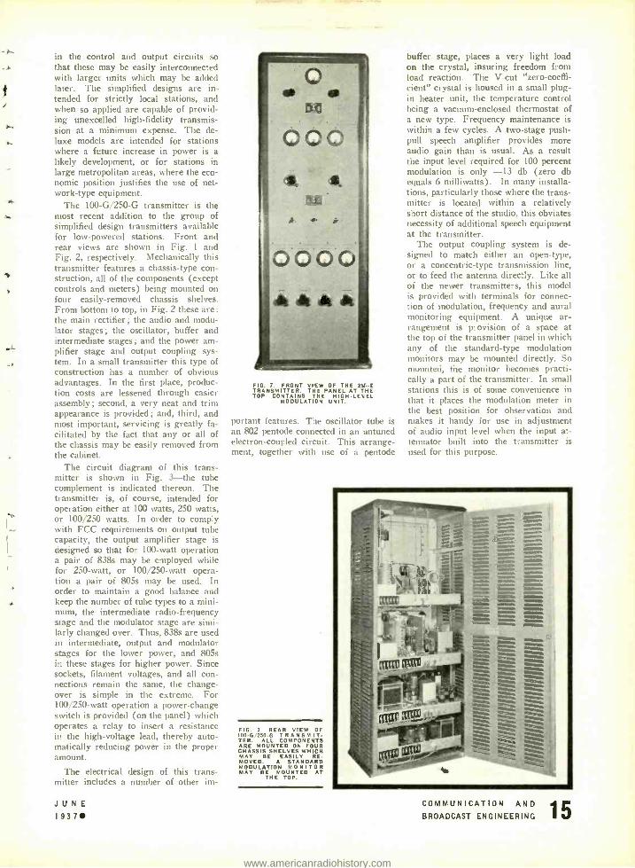
The 100 -G /250 -G transmitter is the most recent addition to the group of simplified design transmitters available for low- powered stations. Front and rear views are shown in Fig. 1 and Fig. 2, respectively. Mechanically this transmitter features a chassis -type con- struction, all of the components (except controls and meters) being mounted on four easily- removed chassis shelves. From bottom to top, in Fig. 2 these are :
the main rectifier ; the audio and modu- lator stages; the oscillator, buffer and intermediate stages; and the power am- plifier stage and output coupling sys- tem. In a small transmitter this type of construction has a number of obvious advantages. In the first place, produc- tion costs are lessened through easier assembly; second, a very neat and trim appearance is provided; and, third, and most important, servicing is greatly fa- cilitated by the fact that any or all of the chassis may be easily removed from the cabinet.
The circuit diagram of this trans- mitter is shown in Fig. 3 -the tube complement is indicated thereon. The transmitter is, of course, intended for operation either at 100 watts, 250 watts, or 100/250 watts. In order to comply with FCC requirements on output tube capacity, the output amplifier stage is designed so that for 100 -watt operation a pair of 838s may be employed while for 250 -watt, or 100 /250 -watt opera- tion a pair of 805s may be used. In order to maintain a good balance and keep the number of tube types to a mini- mum, the intermediate radio- frequency stage and the modulator stage are simi- larly changed over. Thus, 838s are used in intermediate, output and modulator stages for the lower power, and 805s in these stages for higher power. Since sockets, filament voltages, and all con- nections remain the same, the change- over is simple in the extreme. For 100 /250 -watt operation a power -change switch is provided (on the panel) which operates a relay to insert a resistance it the high -voltage lead, thereby auto- matically reducing power in the proper amount.
The electrical design of this trans- mitter includes a number of other im-
JUNE 937
FIG. 7. FRONT VIEW OF THE 25G -E TRANSMITTER. THE PANEL AT THE TOP CONTAINS THE HIGHLEVEL
MODULATION UNIT.
portant features. The oscillator tube is an 802 pentode connected in an untuned electron -coupled circuit. This arrange- ment, together with use of a pentode
FIG. 2. REAR VIEW OF 100- G;250 -G TRANSMIT- TER. ALL COMPONENTS ARE MOUNTED ON FOUR CHASSIS SHELVES WHICH MAY BE EASILY RE- MOVED. A STANDARD MODULATION MONITOR MAY BE MOUNTED AT
THE TOP.
buffer stage, places a very light load on the crystal, insuring freedom from load reaction. The V -cut "zero- coeffi- cient" crystal is housed in a small plug - in heater unit, the temperature control being a vacuum- enclosed thermostat of a new type. Frequency maintenance is within a few cycles. A two -stage push - pull speech amplifier provides more audio gain than is usual. As a result the input level required for 100 percent modulation is only -13 db (zero db equals 6 milliwatts). In many installa- tions, particularly those where the trans- mitter is located within a relatively short distance of the studio, this obviates necessity of additional speech equipment at the transmitter.
The output coupling system is de- signed to match either an open -type, or a concentric -type transmission line, or to feed the antenna directly. Like all of the newer transmitters, this model is provided with terminals for connec- tion of modulation, frequency and aural monitoring equipment. A unique ar- rangement is provision of a space at the top of the transmitter panel in which any of the standard -type modulation monitors may be mounted directly. So mounted, the monitor becomes practi- cally a part of the transmitter. In small stations this is of some convenience in that it places the modulation meter in the best position for observation and makes it handy for use in adjustment of audio input level when the input at- tenuator built into the transmitter is used for this purpose.
- d r. . ' .+ ...
trp_ MOW..
Í
¡
e = i owa .. ? loom.
mm ammo*
.=mow.
COMMUNICATION AND BROADCAST ENGINEERING
www.americanradiohistory.com
a sp
.d w
.'s
u
t
T s': 0:3 i" .
°1 i
L.,-,,,..r
T L
át - ^ o
Ír; o
r
Ll 1_. 143 1 3
JUNE b 1937
THE I00-H /250 -D TRANSMITTER
This transmitter is the newest of the deluxe models. Like the transmitter described previously, it is for use either as a 100 -watt transmitter (in which case it is specified as the Type 100 -H) or as a 250 -watt, or 100/250 - watt transmitter (in which case it is specified as a Type 250 -D). The tube complement also is somewhat similar. At this point, however, the corres- pondence ends. Since this unit is also intended for use as the exciter unit in higher -powered transmitters (in which case it is specified as the 250 -F), it has been designed not only to match in construction and appearance the high - power units, but also to be best -adapted for use with these latter (in respect to the necessary interconnecting of cir- cuits and obtaining of suitable overall performance characteristics).
The most obvious difference between this transmitter and those of simplified design is, of course, in exterior appear- ance (see Fig. 4). Moreover, as soon as the doors are opened, it is obvious that the whole construction, interior as well as exterior, is quite different. The overall dimensions are, of course, greater than in the simplified designs. This allows the unit to match sym- metrically the higher -powered units, which are of necessity larger in size. Moreover, it allows the equipment to be arranged so that tubes can be reached from the front. This is essential in larger transmitters, since the method of installing these (that is, side by side -or even in the side wall of the room) would cause some loss of time if it were necessary to change tubes from the back. In addition to these strictly utilitarian features, the appear- ance of this deluxe unit is, of course, such as to give a richer affect. Stream- lining is evident in every detail, as well as is the size and shape of the various panels. Controls are centralized on one small panel, and all of the tuning controls (requiring only infrequent re- adjustment) are recessed. Meters are located on tilted panels at the top and indirectly illuminated.
Looking inside the transmitter, it is found that an entirely new type of con- struction has been employed. All of the components are mounted on what is referred to as "vertical- chassis." There are two of these, one containing the r -f circuits, and the other the audio and power circuits. Each is as high as, and half the width of, the transmitter unit. All of the components, except the tubes, are mounted on the rear of these vertical chassis, while the tubes are mounted in corresponding positions (that is, with reference to their place in the circuit) on small shelves on the
COMMUNICATION AND
BROADCAST ENGINEERING
t
.4
-4
r
4.
ti
www.americanradiohistory.com

front of the chassis. This method of construction has several unique ad- vantages. When the front doors are opened all of the tubes are instantly accessible, but at the same time all other components, and wiring are hid- den from view. On the other hand, when the back doors are opened all of the circuit components are immediately in view and fully accessible for test or servicing. Finally, of course, the ar- rangement retains the advantageous production possibilities general to chas- sis -type constructions.
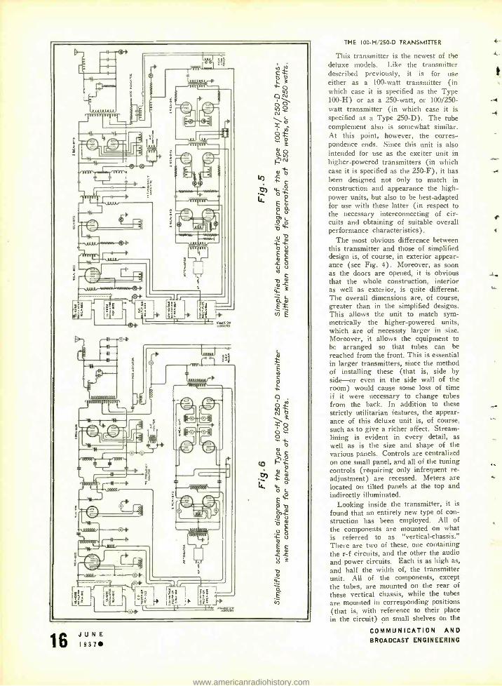
As previously noted, this transmitter is adapted for three modes of operation. The changes from one to another are somewhat, but not greatly, more com- plicated than in the simplified trans- mitter. The connections for 250 -watt, or 100 /250 -watt operation are shown in Fig. 5. As will be noted, the tube complement and the circuits are quite similar to those of the 250 -G transmit- ter. However, two complete oscillator units, and three separate rectifiers, are furnished. The driver audio stage is also of larger capacity, the reason for this being noted hereafter. The connec- tions for 100 -watt operation are indi- cated in Fig. 6. As in the previously described transmitter, the change in the power amplifier consists simply in re- placing the 805's with a pair of 838's. In the modulator stage the change con- sists of combining the driver and output stages (of Fig. 5) to form a single modulator stage using four 845's in push -pull parallel. Sockets, filament voltages and transformers remain the same -the only connection changes re- quired being paralleling of the grid and plate connections.
In addition to these two connection arrangements still others are possible, and are made use of when the unit is used as an exciter. They will, of course, depend on the power of the added units. For instance, in the case of a 1 -kw transmitter, where high -level modula- tion is used, the audio circuits drive the modulators (849's) in the added unit, while the r -f circuits excite the r -f stage of the latter. In the case of the 5 -kw transmitter where limitations of available tube sizes make linear op- eration desirable-the unit is connected approximately as for 250 -watt opera- tion, and as such forms the low -im- pedance driver necessary to obtain high step -up and low distortion in the fol- lowing linear amplifier.
The chief advantage of this trans- mitter over the simplified designs is, of course, in the provision for future power increase. For the most part this consists of details not easy to bring out in a short description. For instance, there is the consideration given to pos-
t (unfinuert on page 36)
JUNE 1937
;.1
.
3
-10-3
I f 1474t. ` i F
Lt 'L.{Ji_- i:
o
o
o
il
W r~
1
I I .. tt
COMMUNICATION AND I BROADCAST ENGINEERING
www.americanradiohistory.com
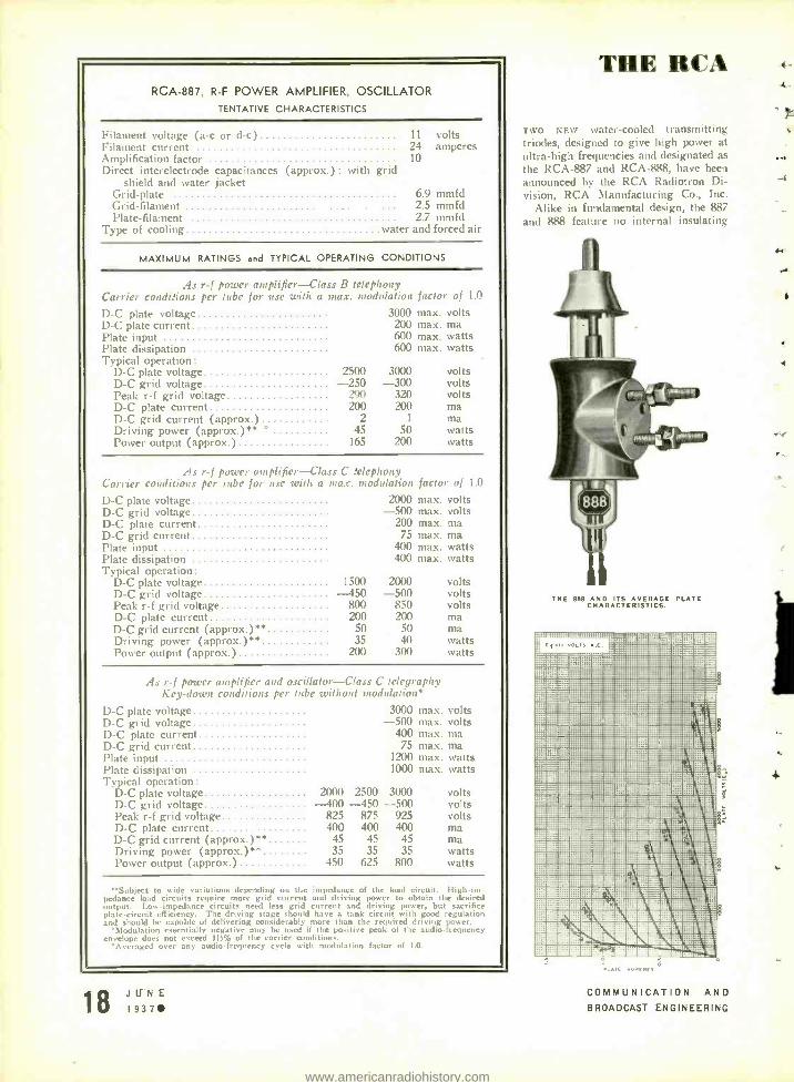
RCA -887, R -F POWER AMPLIFIER, OSCILLATOR TENTATIVE CHARACTERISTICS
Filament voltage (a -c or d -c) Filament current Amplification factor Direct interelectrode capacitances (approx.) : with grid
shield and water jacket Grid -plate 6.9 mmfd Grid -filament ... 2.5 mmfd Plate -filament 2.7 mmfd
Type of cooling tvater and forced air
11 colt, 24 amperes 10
MAXIMUM RATINGS and TYPICAL OPERATING CONDITIONS
As r -f power amplifier -Class B telephony t errier conditions per tube for use with a max. modulation factor 01 1.1'
D -C plate voltage 3000 max. volts D -C plate current 200 max. nia Plate input 600 max. watts Plate dissipation 600 max. watts 'l'vpical operation:
1) -C plate voltage 2500 3000 volts 1) -C grid voltage -250 -300 volts l'eak r -f grid voltage 290 320 volts 1) -C plate current 200 200 ma 1) -C grid current (approx.) 2 1 ma Driving power (approx.) ** ° 45 50 watts Power output (approx.) 165 200 watts
.-ls r -f power amplifier -Class C .'elephoav Carrier conditions per tube for use with a max. modulation factor of 1.0
D -C plate voltage 2000 max. volts D -C grid voltage -500 max. volts D -C plate current 200 max. ma D -C grid current 75 max. ma Plate input 400 max. w:r, Plate dissipation 400 max. tv:. Typical operation :
D -C plate voltage 1500 2000 volts D -C grid voltage -450 -500 volts Peak r -f grid voltage 800 850 volts I) -C plate current 200 200 ma 1)-C grid current (approx.) ** 50 50 ma Driving power (approx.) ** 35 40 watts Power output (approx.) 200 300 watts
is r -f power amplifier and oscillator -Class C telegraphy Key-down conditions per tube without modulations
D -C plate voltage D -C grid voltage D -C plate current
3000 -500
400
max. volts max. volts max. ma
D -C grid current 75 max. ma Plate input 1200 max. watts Plate dissipation 1000 max. watts Typical operation :
D -C plate voltage 2000 2500 3000 volts D -C grid voltage -400 -450 -500 volts Peak r -f grid voltage 825 875 925 volts 1) -C plate current 400 400 400 ma D -C grid current (approx.) ** 45 45 45 ma Driving power (approx.) ** 35 35 35 watts Power output ( approx ) 450 625 800 watts
Subject to wide variations depending on the impedance of the load circuit. High -fin pedance load circuits require more grid current and driving power to obtain the desired output. Low- impedance circuits need less grid current and driving power, but sacrifice plate- circuit efficiency. The driving stage should have a tank circuit with good regulation and should be capable of delivering considerably more than the required driving power.
`Modulation essentially negative may he used if the positive peak of the audio -frequency envelope does not exceed 115% of the carrier conditions.
`Averaged over any audio -frequency cycle with modulation factor of 1.0.
18 JIJNE I937
THE RCA
-1-wo NEW water- cooled transmitting triodes, designed to give high power at
ultra -high frequencies and designated as
the RCA -887 and RCA -888, have been
:announced by the RCA Radiotron Di- vision, RCA Manufacturing Co., Inc.
Alike in fundamental design, the 887
and 888 feature no internal insulating
THE SSN AND ITS AVERAGE PLATE CHARACTERISTICS.
COMMUNICATION AND BROADCAST ENGINEERING
..
4
www.americanradiohistory.com
ri
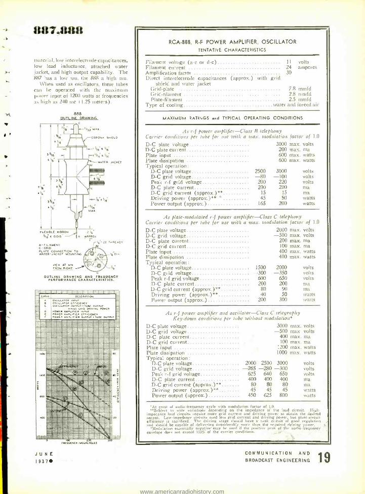
887.888
material. low interelectrode capacitance,. low lead inductance, attached water jacket, and high output capability. The 887 has a low mu. the 888 a high mu.
When used as oscillators, these tubes can be operated with the maximum power input of 12(X) watts at frequencies as high as 240 nie ( 1.25 meters).
888 OUTLINE DRAWING
C
T,b
CORONA SHIELD
IfIL16"t'i6 321; t
M
2
O ty
FLEXIBLE RIBBON
i}a X 0015"
HA- Vt IS,IB
MAX
2 %¡ A APPROA
A- FILAMENT C -GRID PLATE CONNECTION TO WATER - JACKET MOUNTING
JIEW AT MN FROM RIGHT
28 THREADS
,B
OUTLINE DRAWING AND FREQUENCY PERFORMANCE CHARACTERISTICS.
-II$SEE®WMMM!esIMIs®®®818 _ 12:021=11111MEZIE
A
R C
C
_-
r
osCILLlOR INPUT OSCILLlOR CrrCICNCY OSCILLATO. OUTPUT TUSK o
MINUS GRID DRIVINO POWCR POMCR MRIrICR INPUT POWER P IC Cr,, ICCI PowC YPNR N
R hCII OUTPUT uRC OUIPVT
-a.ï C.....C.._-.._. :.-.:_ - :::........_0. DSOS -
= '. _::::ffl E l :::...:...._ M. _. a:!!aa-::::.:i:: _:;rM
'"x =-11180=:-rlr mu=::«: re- :-_::::_: - _...__.._ _..._._.........._ -:_T-._.... ........ _........-..
::.:.r... ._. . - - =..:::.-:,.. . ....
::c:: »!EE ...................
ao
zao
H ' ;
:a:nss' - - - - = w Silzl:.:r:-µ',:~ :!!"::: -=i :L::.-^,.^.^ :ái:!.
_
`
=xt.. : `æG: :... ':::a.:ñ5is:.tgxa:ti.: i:w2.. fr"'
µ » : r-lMi
Ple°=_aik.lú :Ç:.RItial:Y s.ndm... á.. ..:x.. 1...eF'_.::..Lm.-.aiä ' .. 4sá.:
ae.^. .:s ;se' .;::_= E:-E A1ME4
.4.. ' - L
. ?sr rs oo
.._..::::4"
Eä!! ::::::: ._i?'s m e. zo :A :.. 0-.:::'-7-.--'.. ::2!'_:!W!xt
r a .::: ..r. c = =.r ii
oo £00 rRCOUCNCT MEGACYCLES
JUNE 1937
RCA -888, R -F POWER AMPLIFIER, OSCILLATOR
TENTATIVE CHARACTERISTICS
l' Ilan kilt voltage 11t -C Ili' II -c 1
Filament current Amplification factor Direct interelectrode capacitances (approx.) with grid
shield and water jacket Grid -plate 7.8 mmfd ( *riel- filament 2.8 nunfd Plate- filament 2.5 mmfd
Type of cooling water and forced air
1I volts 24 amperes 30
MAXIMUM RATINGS and TYPICAL OPERATING CONDITIONS
As r -f postier amplifier-Class B telephony arricr coudi :ions per tube for use with a max. modulation factor of 1.0
D -C plate voltage D -C plate current Plate input Plate dissipation Typical operation:
D -C plate voltage D -C grid voltage Peak r -f grid voltage D -C plate current D -C grid current (approx.) ** Driving power (approx.) ** °
Power output (approx.)
2500 -80
200 200
15 45
165
3000 max. volts 200 max. ma 600 max. watts 600 max. watts
3000 -100
220 200
15 50
200
volts volts volts ma ma watts watts
As plate -modulated r -f power amplifier -Class C telephony Carrier conditions per tube for use with a max. modulation factor of LO
D -C plate voltage 2000 max. volts D -C grid voltage -500 max. volts D -C plate current 200 max. ma 1) -C grid current 100 max. ma l'late input 400 max. watts Plate dissipation 400 max. watts Typical operation:
D -C plate voltage 1500 2000 volts D -C grid voltage -300 -350 volts Peak r -f grid voltage 600 650 volt, D -C plate current 200 200 nia D -C grid current (approx.) ** 80 90 ma Driving power (approx.) ** 40 50 watts Power output (approx.) 200 300 watts
As r -f pottier amplifier and oscillator -Class C telegraphy Key -down conditions per tube without modulation*
1) -C plate voltage D -C grid voltage D -C plate current D -C grid current
3000 max. volts -500 max. volts
400 max. ma 100 max. ma
Plate input 1200 max. watts Plate dissipation 1000 max. watts Typical operation :
D -C plate voltage 2000- 2500 3000 volts D -C grid voltage -265 -280 -300 volts Peak r -f grid voltage 625 640 650 volts D -C plate current 400 400 400 ma D -C grid current (approx.) ** 80 80 80 ma Driving power (approx.) ** 45 45 45 watts Power output (approx.) 450 625 800 watts
°At crest of audio -frequency cycle with modulation factor of 1.0. ''''Subject to wide variations depending on the impedance of the load circuit. High
impedance load circuits require more grid current and driving power to obtain the desired output. Low- impedance circuits need less grid current and driving power, but plate- circui. efficiency is sacrificed. The driving stage should have a tank circuit of good regulation, and should be capable of delivering considerably more than the required driving power.
*Modulation essentially negative' may be used if the positive peak of the audio -frequency envelope does not exceed 115% of the carrier cnnditinnc.
COMMUNICATION AND BROADCAST ENGINEERING
www.americanradiohistory.com
TELEVISION STUDIO CONSIDERATIONS PARI III
By W. C. EDDY, Lieut. U.S.N. Ref.
Studio Director
FARNSWORTH TELEVISION, INC.
IT IS NOT the purpose of this installment to place in circulation a. complete treatise on television studio lighting. Rather than attempt to cover this com- plex art in its entirety, we will limit ourselves to a discussion of certain phases of both the engineering and artistic aspects that have immediate ap- plication in this specialized field. Some of these considerations are necessarily new to the lighting engineer while others have been proved by time in the associated fields of the stage and moving pictures.
We believe that studio lighting for the video arts will resolve itself into a com- bination of the technique of the por- trait photographer and that of the stage. It is unquestionably true that our levels of illumination will be extremely high but experimentation has shown that the methods of application will conform with standard practice. If we may be ex- cused for generalizing for a moment, let us consider some of the functional char- acteristics of light. It is first of all a means of revealing the subject to the
audience. In the specific case of tele- vision, it is a means of creating an electronic image on the photoelectric cathode of the camera tube. When this image has been produced, regardless of the qualities of depth and tone that might be lacking, this first function of light has been fulfilled.
The second general characteristic of light is that of emotion, and it is here that we find the widest scope for in- genuity on the part of the studio en- gineer. With it he can create or de- stroy the effect of dimension and by judicious use of this same light can portray the full spectrum of human emo- tions. Good lighting then, be it studio or stage, should take into consideration these two major functions of light, il- lumination and sensation, if the maxi- mum returns are to be expected from this utility.
It is possible to subdivide either of these main classifications into three methods of control, namely quantity, color, and distribution. In television we find the first of these controllable prop-
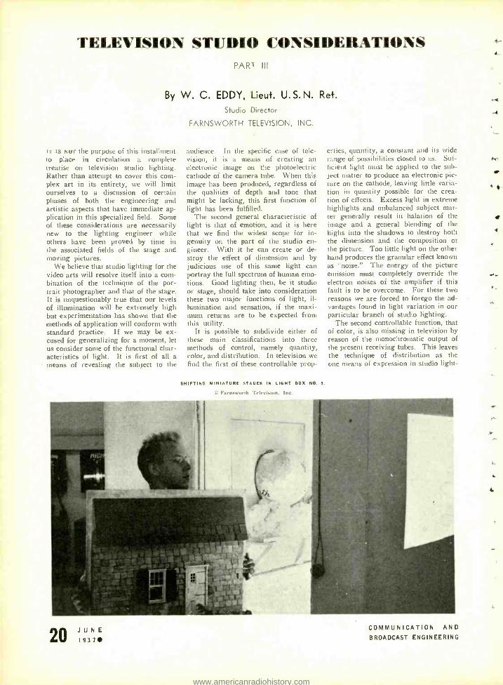
SHIFTING MINIATURE STAGES IN LIGHT BOX NO. I.
P..1 n.wurth Television, Inc.
crties, quantity, a constant and its wide range of possibilities closed to us. Suf- ficient light must be applied to the sub- ject matter to produce an electronic pic- ture on the cathode, leaving little varia- tion in quantity possible for the crea- tion of effects. Excess light in extreme highlights and unbalanced subject mat- ter generally result in halation of the image and a general blending of the highs into the shadows to destroy both the dimension and the composition of the picture. Too little light on the other hand produces the granular effect known as "noise." The energy of the picture emission must completely override the electron noises of the amplifier if this fault is to be overcome. For these two reasons we are forced to forego the ad- vantages found in light variation in our particular branch of studio lighting.
The second controllable function, that of color, is also missing in television by reason of the monochromatic output of the present receiving tubes. This leaves the technique of distribution as the one means of expression in studio light-
,JIINI COMMUNICATION AND
BROADCAST ENGINEERING
1-
o-4
K-
11/
O.
.r
4.
www.americanradiohistory.com
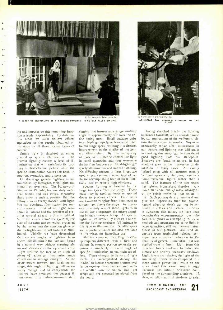
© Farnsworth Television, Inc.
A CLOSE UP CONTINUITY OF A REGULAR PROGRAM. MISS KAY ALLEN SINGING.
ing and imposes on this remaining func- tion a triple responsibility. By distribu- tion alone we must achieve effects equivalent to the results obtained on the stage by all three normal types of control.
Studio light is classified as either general or specific illumination. The general lighting creates a level of il- lumination that will satisfactorily pro- duce a photoelectric picture while the specific illumination covers the fields of emotion, sensation, and dimension.
On the stage general lighting is ac- complished by footlights, strip lights and floods from overhead. The Farnsworth Studios in Philadelphia use only over- head panels and side strips, arranging these units in such a position that the acting area is evenly flooded with light. We use overhead illumination for sev- eral reasons. First of all, light from above is natural and the problem of cre- ating natural effects is thus simplified. With the source above the eyelevel, the eyes Of the actor are somewhat protected by the lashes and the common glare of the footlights and direct broads is ehm- inated. Thirdly we have determined that certain angles of lighting from above will illuminate the face and figurd in a natural way without creating ab- normal shadows in the eyes and chin. Light striking the face at an angle of about 42° gives an illumination angle equivalent to average sunlight. As the actor moves forward and back on the stage, this angle of lighting will neces- sarily change and to compensate for this we have arranged the general il- lumination in a multi- spot -multi -strip
JUNE 19371
rigging that insures an average working angle of approximately 40° over the en- tire acting area. Small wattage units in multiple groups have been substituted for the large spots, resulting in a decided improvement in the quality of the gen- eral illumination. By this multiplicity of spots we are able to control the light in small quantities and thus overcome the familiar bugbears of "band -lighting," spotty illumination and uneven flooding. No diffusing screens or heat filters are used in our system, a novel type of re- flector accomplishing both of these func- tions with extremely high efficiency.
Specific lighting is handled by the large sun spots from the wings. These units may be used as floods or spotted down to produce effects. Four units are available ranging from floor level to sixteen feet above the stage. As a gen- eral rule only one of these lights is in use during a sequence, the others stand- ing by on a twenty -volt tap. All specific lights are controlled by rheostats allow- ing the lighting engineer full latitude in this type of illumination. Smaller spots and a portable panel are also available in the wings for immediate use.
Shifting cameras from long to close up requires different levels of light and change in camera postion generally re- quires a completely different angle of specific illumination to maintain an ef- fect. These changes in lights and light levels are accomplished during the "fades" to insure a constant picture level in the receiver. Such premeditated shifts are written into the control and light script and are executed on signal from the board.
D. Farnsworth Television. Inc.
ADJUSTING THE SPECIFIC LIGHTING IN THE WINGS.
Having sketched briefly the lighting apparatus available, let us consider some logical applications of the medium to ob- tain the maximum in results. We must necessarily strive after naturalness in our picture and lighting that will assist in creating this effect can be considered good lighting from our standpoint. Shadows are found in nature, in fact shadows give us the impression of di- mension in many cases. An evenly lighted cube with all surfaces equally brilliant appears to the casual eye as a two -dimensional figure rather than a solid. The features of the face under flat lighting from ahead dissolve into a two dimensional chalky mask lacking all of the subtle modeling that exists in life. Such portrayals are unnatural and give the impression that the psycho- logical effect of depth can not be ob- tained in a television picture. In order to overcome this fallacy we have done considerable experimentation over the past three years in attempting to devise methods and apparatus for using light in large quantities, still maintaining natur- alness in our pictures. Our first de- parture from established lighting tech- nique was a radical reduction in the quantity of general illumination that was applied from in front. Light from this direction has a tendency to flatten the picture and destroy necessary shadows. Light levels are relative, the light of the sun being infinite when compared to a three candle power bulb while on the other hand this same lamp in total darkness has infinite brilliance com- pared to the surrounding shadows. If, then, we allow natural shadows to exist
COMMUNICATION AND BROADCAST ENGINEERING
www.americanradiohistory.com

MISS I h Television. Inc
MARIE SCHAEFER UNDER HEAV1 MAIN STAGE LIGHTING. NOTE NATURAL CHARACTERISTICS RETAINED.
in our picture, the high lights created by the specific illumination will be
emphasized. On the contrary, if the general illumination is carried at a high level, thé quantity of the specific light must be multiplied many times to over- ride the general and create any semblance of shadow. In other words, rather than adjusting picture levels on the' basis of general illumination, we adjust for the high lights allowing the halftones to carry the impression of depth. This practice boasts another advantage from the economic stand- point. If the general illumination is
carried at too high a level, the high lights brought out by the specific units will undoubtedly appear as irregular flashes until the gain on the entire amplifier system is brought down. In other words we are wasting light and subjecting the performers to unneces- sary glare.
The effect of dimension can be shown in several ways. We can allow normal shadows on the subject to model the features, distinguishing, by reason of the tonal qualities, its dimensional char- acteristics. We can allow the subject to cast a shadow on the background in certain cases or else by judicious use of back -lighting we can silhouette the outline. In some cases all three of these methods are employed together but as a
rule one type of dimensional lighting will suffice for a continuity.
It would be impossible to cover in this or a series of papers all of the considerations that must be taken into account in the use of specific light. Ex- perimentation will bring out new methods of creating effects and con- tinued use will prove established prac- tice. The studio engineer must neces- sarily consider each new setting as a new lighting problem and proceed ac- cordingly. Otherwise he will find him- self in the vicious cycle of "light and more light" until he reaches the fusing point of either the mains or the per- formers themselves.
22 JUNE 193711
Farnsworth Television, Inc. MISS MARY McCREA ON MAIN STAGE FOR A LIGHT CHECK ON HER
NUMBER.
The subject of high and low -key pho- tography was discussed in the first article of this series. In that paper we pointed out that the low -key, high - contrast subject matter would be found more satisfactory for general studio work. This type of picture requires a
minimum of general lighting and the maximum of specific. It has been given the general classification of "dynamic lighting" by photographers and been the subject of several recent books. Ex- ponents of this practice point out its value in satisfying the emotional re- quirements as well as creating dimension in the picture, while the opposition terms it sensationalism and scorns at- tempts to create depth in two dimen- sions. As far as we are concerned, these portrait photographers can have their arguments but we are confronted with the problem of producing a mo- mentary picture on an insensitive re- cording device. If this picture is to carry with it the impression of depth of subject that characterizes the actual model we must accentuate the photo- graphic half tones with artificial highs and lows to insure their reproduction. Failure to build up this normal model- ing results in a shadowless mask punctu- ated with the darks of the eyes, lips and hair. We do not mean to give the im- pression that all television pictures must possess contrast or be in the lower keys. Successful high -key work has been done in our studios on portraiture where the details of lighting are considerably simplified.
The portrait lighting of the an- nouncer's positions presents a some- what different problem. Here the subject is fixed and the quantity of light used is many tinges less than that employed on the main stage. The methods of applying light, however, fol- lows the technique described for the larger sets. We flood on a general light from above of sufficient intensity to il- luminate the entire face. This general lighting itself will bring out some faint
feature modeling which can be accentu- ated as the specific light is brought into play from either side. In such work, where even the halftones are being re- produced, extreme care should be ex- ercized to prevent unnatural shadow areas from forming. Our announcers' desks are equipped with four flexible light mountings so that good dynamic lighting can be accomplished on any type of subject without recourse to port- able units. In certain cases of portrai- ture back lighting of the hair will bring out unusually nice results but this again must be left to the experimentation of the lighting engineer.
As television studio practice continues to develop, the art of studio lighting will advance. As the subject matter on
the stage becomes more complex our lighting problem will necessarily in- crease, but the fundamental theories should remain the same. Naturalness should be the goal of the studio en- gineer and this can be obtained only by
judicious use of light and its antithesis, shadow.
(To be continued)
MIXER CIRCUITS
(Continued from page 11)
one of interlocking the volume control and the disconnect switch. However, in practice, it is usually sufficient merely to disconnect the source leads and not use the compensating resistance Z, at all, since the impedance looking back into a high attenuation T -pad volume control is practically unchanged whether the far end is properly matched, open circuited. or short circuited. It is advisable, how- ever, to have the disconnected source leads short -circuited by this switch and also grounded.
(To hr continued)
COMMUNICATION AND BROADCAST ENGINEERING
www.americanradiohistory.com
r
,
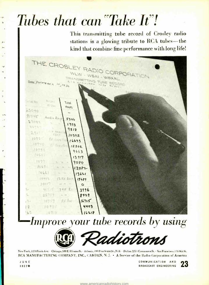
Tubes that can "Take It "!
THE CF-- LEY RA D1
LSgI _ 4sd6X.ra Date: Dvcr,o. tc s,r . /43c. r: 9,
This transmitting tube record of Crosley radio stations is a glowing tribute to RCA tubes -the kind that combine fine performance with long life!
,j
1 otal
out,
- Improve your tube records by using
New York,1270 Sixth Ave. Chicago, 589 E.111 inoie St. Atlanta, 490 Peachtree St., N. E. Dallas, 2211 Commerce St. San Franciaco,170 9th St.
RCA MANUFACTURING COMPANY, INC., CAMDEN, N. J. A Service of the Radio Corporation of America
JUNE 19370
COMMUNICATION AND BROADCAST ENGINEERING
www.americanradiohistory.com
AN A -F .t R -F WIRING DEVICE
THE WIRING of such apparatus as mixer panels, relay and switching panels, etc., has been a much neglected field. Prac- tically no advancement has been made since the early days of radio, and the present type of wiring is mostly a carry- over from standard telephone practice. This was good enough as long as one were satisfied with standard telephone response, and willing to drop out everything above 4,000 cycles. With increased public demand for high -fidel- ity programs radio engineers have had to go to many refinements in an effort to eliminate frequency discrimination.
It was this demand which led the author to the new development which has been named a Panel Wiring Box* and which removes at once all the_, difficulties and undesirable features in- herent in the old -fashioned methods of wiring. The use of shielded wire is
O
RL
110 111
C
F IG. 2. EQUIVALENT CIRCUIT OF WIRING WITH GROUND RETURN.
O
entirely eliminated and the wiring is
pre -fabricated and located in a com- pletely shielded box. This box has a
terminal strip along its entire top fgt. ".'
convenient connection to outside wiring, and the complete structure may be, mounted on the panel, in any convenieint position, with two machine screws;`'see Fig. 1. Where space is a factor, and where terminals can be located close together without fear of leakage, the terminal strip may be located at one end. This is important in r -f work where the use of this feature insures the symmetrical relations of all incom- ing leads.
The wiring inside the box is made with special copper bus bar in two planes, i.e, the longitudinal bars are all in one plane, and the vertical ones in another. This arrangement makes it
'Patent applied for.
JUNE 1937
By MAGNUS BJORNDAL
TECH LABORATORIES
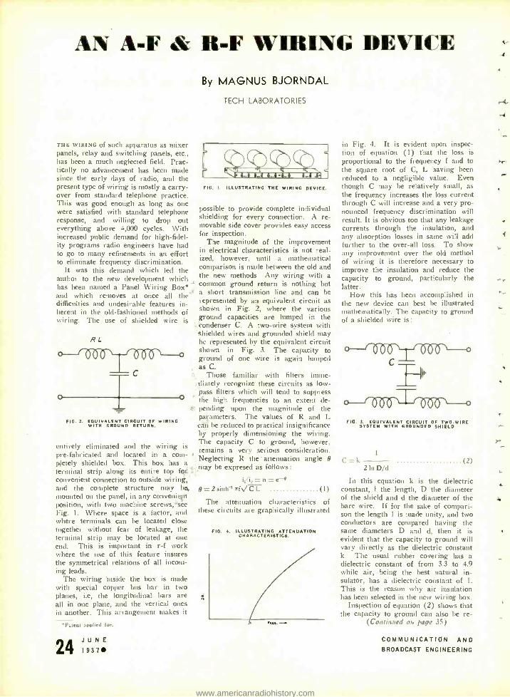
riririri FIG. I. ILLUSTRATING THE WIRING DEVICE.
possible to provide complete individual shielding for every connection. A re- movable side cover provides easy access for inspection.
The magnitude of the improvement in electrical characteristics is not real- ized, however, until a mathematical comparison is made between the old and the new methods. Any wiring with a
common ground return is nothing but a short transmission line and can be represented by an equivalent circuit as shown in Fig. 2, where the various ground capacities are lumped in the
,.'condenser C. A two -wire system with shielded wires and grounded shield may be represented by the equivalent circuit shown in Fig. 3. The capacity to ground of one wire is again lumped as C.
Those familiar with filters imme- diately recognize these circuits as low - ¡pass filters which will tend to suppress the high frequencies to an extent de- pending upon the magnitude of the patameters. The values of R and L cdii be reduced to practical insignificance by properly dimensioning the wiring. The capacity C to ground, however, remains a very serious consideration. Neglecting R the' attenuation angle 9 may be expresed as follows:
i,/i,=n=e g=2sinh-r Th/ CL (1)
The attenuation characteristics of these circuits are graphically illustrated
FIG. 4. ILLUSTRATING ATTENUATION CHARACTERISTICS.
in Fig. 4. It is evident upon inspec- tion of equation (1) that the loss is
proportional to the frequency f and to the square root of C, L having been reduced to a negligible value. Even though C may be relatively small, as
the frequency increases the loss current through C will increase and a very pro- nounced frequency discrimination will result. It is obvious too that any leakage currents through the insulation, and any absorption losses in same will add further to the over -all loss. To show any improvement over the old method of wiring it is therefore necessary to improve the insulation and reduce the capacity to ground, particularly the latter.
How this has been accomplished in the new device can best be illustrated mathematically. The capacity to ground of a shielded wire is:
111 101 FIG. 3. EQUIVALENT CIRCUIT OF TWO -WIRE
SYSTEM WITH GROUNDED SHIELD.
C=k - - - -
2 In ll/d (2)
In this equation k is the dielectric constant, 1 the length, D the diameter of the shield and d the diameter of the bare wire. If for the sake of compari- son the length 1 is made unity, and two conductors are compared having the same diameters D and d, then it is evident that the capacity to ground will vary directly as the dielectric constant k. The usual rubber covering has a dielectric constant of from 3.3 to 4.9 while air, being the best natural in- sulator, has a dielectric constant of 1.
This is the reason why air insulation has been selected in the new wiring box.
Inspection of equation (2) shows that the capacity to ground can also be re-
(Continued on pool' 351
COMMUNICATION AND BROADCAST ENGINEERING
t
4.
www.americanradiohistory.com

BEHIND THE VOICE
High -Voltage rectifiers at 50,000 -watt broadcasting station of WJR, Detroit, Michigan. Built by Western Electric Company
Supplying power to every broadcasting
transmitter is a battery of high -voltage rectifier
tubes. In the better engineered stations Isolantite
is liberally used to harness the power behind
the far -flung voice of radio. Isolantite's unusual
mechanical properties and low
electrical losses make it the
ideal insulation not only for the
high voltage, but also for the
radio frequency circuits of broadcast and other
transmitting equipment. Broaccasting stations
insulated throughout with Isolartite attain
maximum operating efficiency. Isolantite engi-
neers will aid in the design of suitable insulators.
ISOLANTITE INC. CERAMIC INSULATORS FACTORY. BELLEVILLE, N. J. SALES OFFICE. 233 BROADWAY, NEW YOGA, N. Y
JUNE 1937
COMMUNICATION AND BROADCAST ENGINEERING
www.americanradiohistory.com
V 0 VETERAN WIRELESS OPERATORS V 0
ASSOCIATION NEWS
W. J. McGonigle, President, RCA Building, 30 Rockefeller Plaza, New York, N. Y.
HENRY J. HUGHES
THIS MONTH we dedicate our page to the memory of our late beloved member Henry J. Hughes. We can but with difficulty realize that this sterling character, one of the real pioneers in our profession, a fine gentleman, sincere friend and splendid com- rade, beloved and respected by all who knew him, has been called to his reward during the most fruitful years of his long and successful career.
We, his associates in the Veteran Wire- less Operators Association realizing the full extent of our loss, will ever cherish the ideals and principles adhered to through- out life by this grand person.
Our deepest sympathies and condolences are extended to Mrs. Hughes, nee Miss Anna Nevins, who is likewise a real pio- neer in our profession, having become as- sociated with the De Forest Company in early 1906, becoming the wife of Henry J. Hughes in 1910, one of the few women who pioneered the then new art, a mem- ber for life of our Association, and her family.
The following is a tribute titled "The Daddy of the Veterans, an Appreciation," by Jim Baskerville, an early associate of Mr. Hughes', written in 1932.
"Perhaps the best known and most popu- lar of the old Wireless Operators needs no introduction to the Old Timers, many of whom had the pleasure and privilege of associating with him in the early strug- gle of wireless telegraphy, when his high potential pioneering did so much to pro- duce the epic background, from which stands out the brilliant radio of today.
"Henry j. Hughes joined DeForest in 1902 as an expert telegraph operator, using of course the Morse Code. Henry was a young man of high purpose, mighty cour- age and a tenacious worker, with the good habit of success. Here he proved to be the right man, fitted snugly into the right place, who had arrived on the scene at a propitious moment to start something well. Mellowed somewhat now, Henry is today the same splendid man among men that he was in those hectic days removing some of the uncertainties of wireless and encouraging its personnel. His job was without precedent, and his judgment and his conscience his guide. 'Be yourself, Henry' was a sort of a slogan with him -a guarantee of honest sarvice and fair and just treatment to all. His job had a certain toughness, in that he had to take this awkward wireless thing and make it do what the ardent and voluble stock salesman said it would do and some- times these fellows had keen imagination, and covered much area of thought.
"First Henry travelled around the vari- ous cities giving demonstrations. He shot wireless waves through brick walls, con- crete and steel. He showed the uncanny thrill of sending wireless messages from inside a closed bank safe with all its tough metal. An appeal to the imagination! Spark coil, helix, key, tuner, responder,
JUNE 1937
earphones, Henry himself, pad, pencil, and finally the message.
"Soon a demand for distance and more practical use became insistent and on ac- count of his ingenuity and skill Henry be- came one of the most urgently necessary complements of a crude wireless outfit (apologies to Dr. DeForest) the best part of it so it would function properly and to the satisfaction of the stockholders.
"For the convenience of the far sighted and wise ( ?) investors who liked to be convinced, two wireless stations were erected, one at 17 State Street, New York City, and the other at distant Staten Island. An operator H. M. Horton (not the ice - cream man) occupied the New York end to transmit under the eagle eyes of the prospects, and on one very important oc- casion Henry Hughes was sent to Staten Island to handle the receiving end. Much depended on the successful outcome, no alibis accepted. In reality it meant a pay check or no pay check, in direct ratio to the impression created, and Henry, having experienced payless pay days before, al- lowed his mind's eye to conjure up a beau- tiful picture of success, positively allowing no consideration of any alternative.
"Arriving at the station and eager to start something Henry prepared for wire- less reception. With paper and pencil ready Henry pulled in his chair for closer concentration. A vacancy in front of him shocked him. He looked closer, and yes sir, the responder wasn't there! He rubbed his eyes and felt about with his hands but the responder wasn't there. He got up and looked all around, making the search more diligent and thorough when it was so apparently in vain. Refusing to become actively dismayed he told himself that the important test due in a few mo- ments must take effect. How, didn't bother Henry. As he looked at those two va- cant binding posts he studied the situation. Not having the technical details who can say how he solved the problem, copied the messages and got the pay check? Well, he did, by some light contact contraption evolved a coherer effect, and tapped the table gently with his left hand as he copied with his right!
"The New York end after sending the messages once remembered the responder wasn't there and knocked off without even listening in. They called "SI" on the phone to say that the test was off for the day.
"Said Henry 'I copied five and OK'd them. Did you send more?'
"Which goes to show how dumb he wasn't. It's great to call on him today, and warm a few admissions out of him and get him started talking of the old wireless days. His eyes glisten when he talks -With no baggage, not even an extra collar, I caught the Bermudian just as she sailed !" 'And was nearly arrested in Hamilton for working the wireless while in port.' 'The first long distance between ships I think was when leaving Key West
on the Denver I heard the San Jacinto
when lie was leaving New York.' Henry remembers all of the Old Timers and knows much of their history.
"Wireless needed such men as he repre- sented, when he became Chief Operator and later Superintendent his cordial per- sonality was an inspiration to his men. He was the hardest worker among them and appreciated what they had to do. Sometimes when the financial ebb was low and pay wasn't regular, he would say to some of the boys 'Well, go on aboard the ship -they feed you on board even if we don't pay you!'
"Henry fought for good working condi- tions for the operators. He realized and stressed their responsibility. He pointed out that human lives depended upon their courage, ability and endurance. He advo- cated proper quarters and generous treat- ment, and there is no doubt that his stand in those days is largely responsible for the operators' generous treatment today.
"This expression of appreciation is small compared to the man and the tribute he deserves, when he has so lived and so dealt with his fellow man as to remain in their hearts through the years."
AWARD BROADCAST
we FAILED, and regretably so, to mention the name of the man most responsible for the recent broadcast of our Association award to Captain Bjarne Sverdrup of the ill -fated Norwegian freighter Bjerkli -Mr. Gerry Harrison of the Yankee and Colonial Networks Public Relations De- partment. We now extend our grateful appreciation to Mr. Harrison for his whole- hearted cooperation and trust that we may some time be in a position to re- ciprocate. Thanks, again, GH, and 73.
BOSTON
HARRY CHETHAM tells us "What becomes of Old* Timers " -"A Vista of Years Gone By"-."Tropical Seas" -The Southern Cross - beautiful moonlight nights, hur- ricanes, collisions, fire at sea, torpedos, tough skippers, good and bad shipmates - when old "DF" reached the Seven Seas and "CC" pounded out its press- CQD's- SOS's -all a memory now -and what a fall from "Grace" -for now it's "Calling all cars, man suffering from inebriation in the alley" or "Chase the boys off the cor- ner."
HERMAN BRUNING has just returned from a long illness at the Massachusetts General Hospital. . Glad to see you up and around again HB and best wishes for con- tinued good health.... Guy R. Entwistle, president of the Massachusetts Radio and Telegraph School, and his partner, Ray -
(Continued on page 28)
Those who become Police.Radio Operators.
COMMUNICATION AND
BROADCAST ENGINEERING
4
t.
11
4
f
v4
rY
4 .
L
www.americanradiohistory.com

'-'11)3041411111111111111 YD
-00444 . with NO INCREASE IN CARRIER PO
FIE RUZZI
"PROGRAM AMPLIFIER" - latest development of Bell Telephone
Laboratories -gives you better coverage
HAVE you heard about this latest Western Electric pace -setter -the 110A Program Amplifier? Ad-
vance news of what it does has gotten around -and orders have been pouring in. Briefly, here's what it gives you :
1. An increase in average signal level of not less than 3db (equal to doubling the carrier power) ;
2. Limitation of excessive peaks of modulation ;
3. Protection against over -modulation in case of accidental increase in program level;
4. Suppression of Extra Band Radiation (monkey chatter on adjacent channels) by prevention of over -modulation;
5. Continuous visual indication of magnitude and fre- quency of program peaks;
6. Program amplification of line output for feeding the transmitter at proper level.
The basis of this latest Bell Telephone Laboratories achievement is a variable loss network inserted in your program circuit. The loss introduced is con-
JUNE 1937
trolled directly by the instantaneous program level. With such positive control, you can safely raise
your average signal level at least 3db- increasing your effective coverage with no increase in carrier power. Better coverage means more dollars for you. Through Bell Telephone Laboratories research, Western Electric progressiveness, and Graybar ser- vice, you (profit !
Delivery of the 110A will start in June. Write to Graybar for full details and get your order near the top of the pile.
3 Steps in 1 Direction 1927 1931 1937
Western Electric intradores 10Oó modulation (5Oá seed formerlv), effecting 6db gain- giving 1K W trans- miller the effective power of 4K R -.
Western Electric introduces the halfwave radiator (.55 antenna), effecting a 3db gain. The I KW transmitter now becomes an 8KW. Western Electric introduces the Program Amplifier with an effective gain of 3db. With all three features, the modern 1KW transmitter has the effective power of if, kW of the old .tsar.
Western Electric BROADCASTING EQUIPMENT Distributed by GRAY MR Electric Co. In Canada: Northern Ele trlc Co., Ltd.
COMMUNICATION AND BROADCAST ENGINEERING L
www.americanradiohistory.com
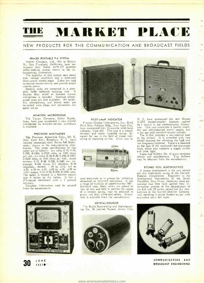
THE MARKET PLACE NEW PRODUCTS FOR THE COMMU NICATION AND BROADCAST FIELDS
REMLER PORTABLE P -A SYSTEM
Remler Company, Ltd., 19th at Bryant St., San Francisco, California, have an- nounced their Model APS -177 portable public- address system shown in the ac- companying illustration.
The amplifier of this system uses metal tube voltage amplifiers and a push -pull beam -power output stage. Tubes are said to operate conservatively and provide ample reserve power.
Speaker units are contained in a port- able, baffle equipped carrying case. A Remler floor stand or banquet crystal microphone is included. Matched phono- graph units are also available. All speak- ers, microphones, and phono units are furnished with plugs and connectors for quick set -up.
AVIATION MICROPHONE The Turner Company, Cedar Rapids,
Iowa, have just announced a new crystal microphone for aviation service. Literature is available.
PRECISION MULTIMETER
The Precision Apparatus Corp., 821 E. New York Ave., Brooklyn, N. Y., have recently announced their Series 840 Multi - meter, shown in the accompanying illus- tration. The range specifications of this meter are as follows : a -c volts, 0-10, 0 -50, 0- 250, 0 -1000, 0 -2500 volts, at 1000 ohms per volt ; d -c volts, 0 -10, 0 -50, 0 -250, 0 -1000, 0 -2500 volts, at 1000 ohms per volt; direct current, 0 -10, 0 -50, 0- 250, 0 -1000 ma; re- sistance, 0 -400 ohms, 0 -1 megohm, 0 -10 megohms ; decibel, -10 to +15, +4 to +29, +18 to +43, +30 to +55, +38 to +63; output, 0 -10, 0-50, 0 -250, 0 -1000 volts. The meter is housed in a bakelite square case 4 inches by 4% inches. It has a d'Arsonval movement with a 2 percent accuracy.
Complete information may be secured from the manufacturer.
.II;B--i `-1111
tTa{S:ID1ï;i?::a-';77511
JUNE 1937
PILOT -LAMP INDICATOR Premier Crystal Laboratories, Inc., 53 -63
Park Row, Pulitzer Bldg., New York City, have announced their Crystalite pilot -lamp indicator, Type 835. This unit is a simple, compact and easily installed device, de- signed for use in the field of visual indi- cating or signaling service. Units may be
used separately or in groups for indicating occasional or recurrent operations. It has a range of visibility of approximately 180 °. Standard color discs, which are placed at scar of lens and held in position by means of a tension spring, may be obtained in green, red, blue, white and yellow. Litera- ture is available from the manufacturer.
CRYSTAL-COUPLER The Radio Engineering and Manufactur-
ing Co., 26 Journal Square, Jersey City,
N. J., have announced the new Remco R -20A crystal- coupler (patents applied for) shown in the accompanying illustra- tion. This unit comprises a special ampli- fier and self -contained power supply, and is for use with standard crystal pickups.
The R -20A provides a non -reactive load to the crystal. It is provided with two circuit controls for adjusting the high and low -frequency response. These are mounted on the face of the machined cast -aluminum head, which also supports a toggle switch and pilot light.
Loose -leaf bulletin No. 12 gives complete details and specifications. This bulletin may be obtained from the manufacturer.
ETCHED FOIL ELECTROLYTICS
A recent development is the new etched foil dry electrolytic series of the Cornell- Dubilier Corporation. Engineers in the development laboratories of the South Plainfield, New Jersey, condenser plant an- nounced that they have applied their hi- formation process to the manufacture of the KR and JR series, etched foil dry elec- trolytics of the Cornell -Dubilier Corpora- tion, resulting in power factors on par with ecuivalent plain foil types.
COMMUNICATION AND BROADCAST ENGINEERING
r
r
www.americanradiohistory.com
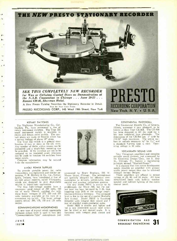
THE NEW PRESTO STATIONARY RECORDER
SEE THIS COMPLETELY NEW RECORDER for Wax or Cellulose Coated Discs on Demonstration at the N.A.B. Convention in Chicago ... June 20 -23 .. .
Rooms 63940, Sherman Hotel. A New Presto Catalog Describes the Stationery Recorder in Detail.
Bend for Your Copy Todoy.
PREST RECORDING CORPORATION
PRESTO RECORDING CORP., 145 West 19th Street, New York
MI New York, NAY. U. S. A.
ROTARY SWITCHES
The Shallcross Manufacturing Co., Col - lingdale, Pa., have announced a line of rotary instrument switches. The Type 531 small instrument switch is available in eleven and fifteen point models. The con- tact plates are made of Steatite which has a normal leakage of above 10" ohms.
The Type 532 switch is a general com- bination of two or more of the 531 units. Any number of decks within reason can be assembled and a single -hole mounting can be provided. If the switches are not to be mounted on an insulated panel, provision can be made to insulate the switches from metal panels.
Complete information may be secured from the manufacturer.
6-VOLT POWER SUPPLIES
To provide portable power for radio transmitters, p -a equipment and similar ap- paratus, P. R. Mallory & Co., Inc., Indian- apolis, Indiana, have introduced a line of six -volt power supplies, called Vibrapacks, which are designed to give dependable service in heavy -duty application.
The two high -voltage models have a maximum rated output of 300 volts, 100 ma of easily filtered, rectified d -c with three lower voltages of 275, 250 and 225 volts instantly available at the turn of a convenient tap switch. The lower voltage models deliver 200, 175, 150 and 125 volts output.
COMMUNICATIONS MICROPHONES A new type of crystal which appreciably
increases output level is used in two new "Communications -Type" microphones just
JUNE 19370
announced by Shure Brothers, 225 W. Huron Street, Chicago. The microphones are specially designed for effective com- munication in airways, police- radio, com- mercial and amateur radiophone systems.
The new Model 70S \V is similar to its predecessor, the Shure 70S, but the out- put level has been increased by 5 db, thus requiring only 56% of the voltage ampli- fication previously necessary. The increased level is due to the use of a special Rochelle Salt crystal. Model 70SW is furnished complete with integral desk mount and 7
feet of shielded single- conductor cable. Model 703S is smaller and lighter and
has a new convenient swivel head which can be tilted at any desired angle. It is furnished with integral. .desk mount and cable.
CONTINENTAL PHOTOCELL The Continental Electric Co., of Geneva,
Illinois, announce a new photocell to be known as their Type CE -868. The CE -868 has been designed to fill the need for a low cost industrial type phototube. The dimensions of the CE -868 are 1" wide by 3 -9/32" high maximum. The active sur- face or cathode measures %" by 11/z" and a standard 4-prong base is used. Oper- ating voltage is 90 volts.
VOCAGRAPH SOUND LINE New Vocagraph amplifiers and complete
portable sound systems, just announced by the Electronic Design Corp., 164 N. May St., Chicago, Ill., feature a reproducing principle termed "Hushed- Power."
It is claimed that this recent development makes possible an amplifier with greater usable power output than can be achieved through former designs.
These amplifiers are offered in output ratings of 20, 40, and 60 watts. All have streamlined cases with built -in monitor speaker and indirect lighting of the entire control panel.
COMMUNICATION AND
BROADCAST ENGINEERING 3
www.americanradiohistory.com
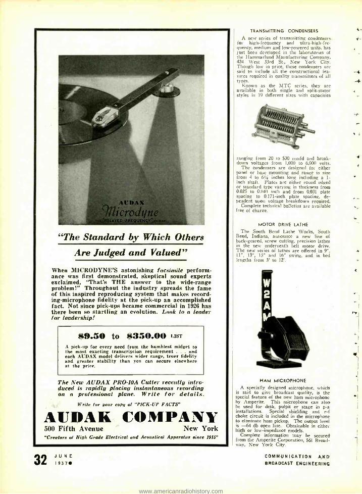
.
"The Standard by Which Others
Are Judged and Valued"
When MICRODYNE'S astonishing facsimile perform- ance was first demonstrated, skeptical sound experts exclaimed, "That's THE answer to the wide -range problem!" Throughout the industry spreads the fame of this inspired reproducing system that makes record- ing- microphone fidelity at the pick -up an accomplished fact. Not since pick -ups became commercial in 1926 has there been so startling an evolution. Look to a leader for leadership!
$9.50 to $350.00 LIST
A pick -up for every need from the humblest midget to the most exacting transcription requirement and each AUDAX model delivers wider range, truer fidelity and greater stability than you can secure elsewhere at the price.
The New AUDAX PRO -10A Cutter recently intro- duced is rapidly placing instantaneous recording on a professional plane. Write for details.
Write for your copy of "PICK -UP FACTS"
:AIJDAK COMPANY 500 Fifth Avenue New York "Creators of Nigh Grade Electrical and Acoustical .4pparatus since 1915"
JUNE L 1 937
TRANSMITTING CONDENSERS
A new series of transmitting condensers for high- frequency and ultra- high -fre- quency, medium and low- powered units, has just been developed in the laboratories of the Hammarlund Manufacturing Company. 424 West 33rd St., New York City. Though low in price, these condensers are said to include all the constructional fea- tures required in quality transmitters of all types.
Known as the MTC series, they are available in both single and split- stator styles in 19 different sizes with capacities
ranging from 20 to 530 mmfd and break- down voltages from 1,000 to 6,000 volts.
The condensers are designed for either panel or base mounting and range in size from 4 to 6% inches long including a f- inch shaft. Plates are either round edged or standard type varying in thickness from 0.025 to 0.040 inch and from 0.031 plate spacing to 0.171 -inch plate spacing, de- pendent upon voltage breakdown required.
Complete technical bulletins are available free of charge.
MOTOR DRIVE LATHE
The South Bend Lathe Works, South Bend, Indiana, announce a new line of back- geared, screw cutting, precision lathes in the new underneath belt motor drive. The new series of lathes are offered in 9 ", 11 ", 13 ", 15" and 16" swing, and in bed lengths from 3' to 12'.
HAM MICROPHONE
A specially designed microphone, which is said to give broadcast quality, is the special feature of the new ham microphone by Amperite. This microphone can also be used for desk, pulpit or stage in p -a installations. Special shielding and r -f choke circuit is included in the microphone to eliminate hum pickup. The output level is -64 db open line. Obtainable in either high or low- impedance models.
Complete information may be secured from the Amperite Corporation, 561 Broad- way, New York City.
COMMUNICATION AND BROADCAST ENGINEERING
4-
-4.
4.
4
4
www.americanradiohistory.com
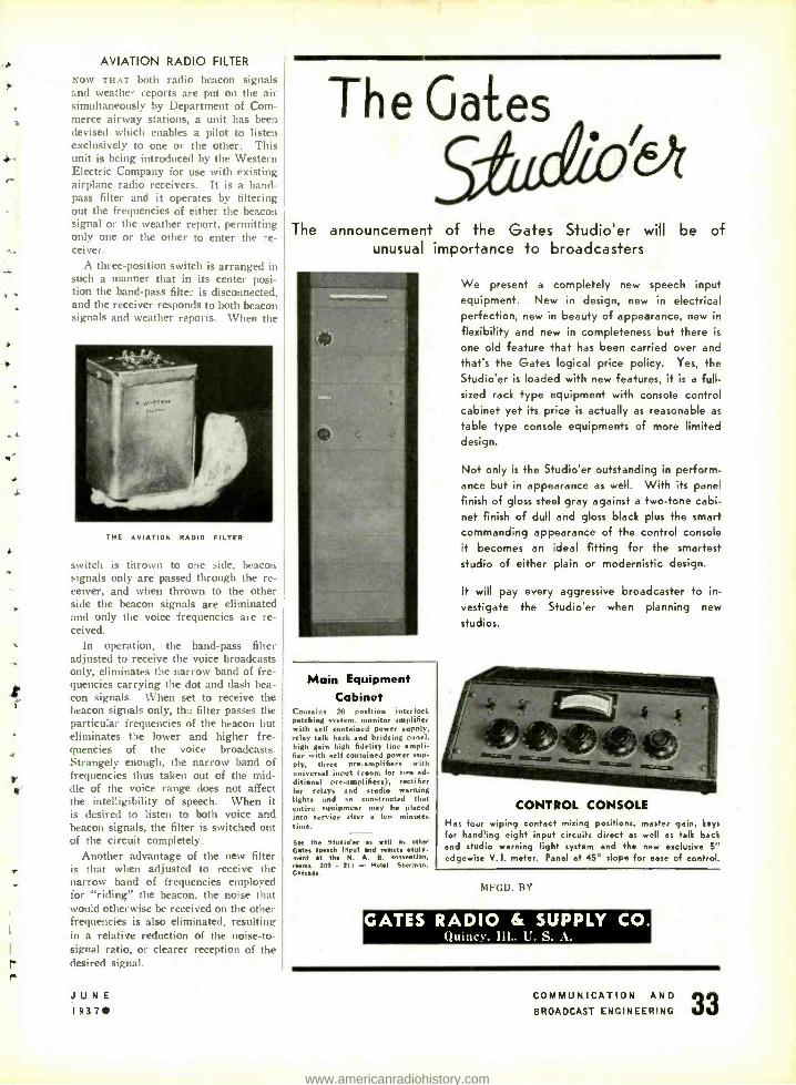
r--
t
AVIATION RADIO FILTER
NOW THAT both radio beacon signals and weather reports are put on the air simultaneously by Department of Com- merce airway stations, a unit has been devised which enables a pilot to listen exclusively to one or the other. This unit is being introduced by the Western Electric Company for use with existing airplane radio receivers. It is a band - pass filter and it operates by filtering out the frequencies of either the beacon signal or the weather report, permitting only one or the other to enter the re- ceiver.
A three -position switch is arranged in such a manner that in its center posi- tion the band -pass filter is disconnected, and the receiver responds to both beacon signals and weather reports. When the
Th e Gates
The announcement of the Gates Studio'er will be of unusual importance to broadcasters
THE AVIATION RADIO FILTER
switch is thrown to one side, beacon signals only are passed through the re- ceiver, and when thrown to the other side the beacon signals are eliminated and only the voice frequencies are re- ceived.
In operation, the band -pass filter adjusted to receive the voice broadcasts only, eliminates the narrow band of fre- quencies carrying the dot and dash bea- con signals. When set to receive the beacon signals only, th: filter passes the particular frequencies of the beacon but eliminates the lower and higher fre- quencies of the voice broadcasts. Strangely enough, the narrow band of frequencies thus taken out of the mid- dle of the voice range does not affect the intelligibility of speech. When it is desired to listen to both voice and beacon signals, the filter is switched out of the circuit completely.
Another advantage of the new filter is that when adjusted to receive the narrow band of frequencies employed for "riding" the beacon, the noise that would otherwise be received on the other frequencies is also eliminated, resulting in a relative reduction of the noise -to- signal ratio, or clearer reception of the desired signal.
JUNE 1937
Main Equipment Cabinet
Contains 20 position interlock patching system. monitor amplifier with self contained power sup,ly, relay talk beck and bridging penal. high gain high fidelity line mpli- fier with sell contained power sup- ply, three preamplifiers with uni I input I room for two ad- ditional pre -amplifiers), rectifier for relays and studio
r ning
lights and constructed that
entire equipment "may be placed into service after a few minute. time.
See the Studio'er as well as other Gates speech input and remoteepuip-
ent at the N. A. B. onvention. rooms 209 . 211 - Hotel
a
Shermsn. Chita So.
We present a completely new speech input equipment. New in design, new in electrical perfection, new in beauty of appearance, new in
flexibility and new in completeness but there is
one old feature that has been carried over and
that's the Gates logical price policy. Yes, the
Studio'er is loaded with new features, it is a full - sized rack type equipment with console control cabinet yet its price is actually as reasonable as
table type console equipments of more limited design.
Not only is the Studio'er outstanding in perform- ance but in appearance as well. With its panel
finish of gloss steel gray against a two -tone cabi- net finish of dull and gloss black plus the smart
commanding appearance of the control console
it becomes an ideal fitting for the smartest
studio of either plain or modernistic design.
It will pay every aggressive broadcaster to in-
vestigate the Studio'er when planning new
studios.
CONTROL CONSOLE Has four wiping contact mixing positions, master gain, keys
For handling eight input circuits direct as well as talk back and studio warning light system and the new exclusive 5" edgewise V. I. meter. Panel at 45° slope for ease of control.
DIFGD. BY
GATES RADIO & SUPPLY CO. (;luinc%. Ill.. t . S..1.
COMMUNICATION AND
33 BROADCAST ENGINEERING
www.americanradiohistory.com

NAB CONVENTION (Continued from page 8)
Resolutions pertaining to the Com- mercial Section.
2:00 P. M. Call to Order A Panel Discussion -MR. H. K. CAR-
PENTER, WHK, Chairman How Should a Station Service Its
Local Accounts? MR. MARVIN ORECK -MR. LEWIS H.
AVERY
How Can We Simplify Our Rate Cards ?
MR. JOHN J. GILLIN, JR. -MR. MAR- TIN CAMPBELL
How Can Our Present Methods of Securing National Spot Business Be Improved?
MR. JOHN J. GILLIN, JR. -MR. AR- THUR B. CHURCH
How Can Creative Selling Be En- couraged?
MR. ARTHUR PRYOR, JR.-MR. AR- THUR B. CHURCH
What Information Should Stations Release with Respect to their "Circulation "?
MR. H. K. CARPENTER -MR. MARTIN CAMPBELL
What Is Your Definition of the Tern] "Merchandising "?
Installation of Officers Annual NAB Banquet
LYNCH GIANT KILLER CABLE
Has no superior for any and all types
of rodio frequency transmitting and
receiving systems.
Not only endorsed by, but used by
leading radio experts everywhere.
World's largest Makers of Antenna Systems
L. S. BRACH Mfg. Corp. Newark, N. J. .4 :01. Est. 1906
for Smooth
Control of Voltage
To regulate A. C. Lines
Power
Speed
Heat
Light
Use TRANSTAT* REGULATORS
Used for numerous voltage - control applications because of its many advantages over re- sistive and tap- changing devices. Features are: High efficiency, good regulation, great flexibility. Voltage may be changed gradu- ally, and without interrupting the circuit, from zero to values higher than line voltage. Well suited for large and small voltage -control problems. Equipment available for manual, motor, and automatic control of voltage of any com- mercial freqeuncy in single -phase or polyphase circuits.
'Patents 1.993,007 and 2,014,570: other patents pending: Trenstat trade -mark registered U. S. Patent Office.
Send
for Bulletin
1176
for complete
data
AMERICAN TRANSFORMER COMPANY
175 EMMET ST. NEWARK, N. J.
JUNE ( I937
TOTALLY NEW MICROPHONE
SHURE "TRI- POLAR" 1.
Uni- Directional 2.
Bi- Directional 3.
Non -Directional
All in ONE Unit! Nov,, through the new Shure "Con- trolled-Direction" principle, you can have all three basically- different direc- tional characteristics is one micro- phone -each instantly available through a 3 -point selector switch. 1. Usti- Directional. Widengle front -side pickup- dead at reer. Cuts out audience n oise, reduces reverberation energy. pickup 66%, eliminates feedback. The first eco- n omical microphone of any type to give you this feature! Output level 63 db below I volt per bar.
2. Bi- Directional. Typical velocity chorea- teristic with pickup from front and bark- - dead at both sides. Allows artist placement Iront and back, reduces reverberation energy pickup 66';. prevents feedback. The first practical crystal microphone to give you this feature! Output level 68 db below I volt per bar.
3. Non -Directional. Full 360 -decree a((- around pickup for group presentations and general applications. Outut level 53 db below 1 volt per bar.
The Shure "Tri- Polar" Crystal Micro- phone has a smooth wide -range fre- quency response from 40 to 10,000
cycles. It is rugged, light, and com- pact. Operates on conventional high - gain crystal microphone amplifiers. List Price, complete with 25 feet
cable $39.50 Available after August 1. 1937
For complete information, write for Bulletin 145C Shure patents pending. Licensed under Went: of the Brush Development Company.
S NORIO SF SNICASS SSC
H U R f )IVI, - CA
e/n COORS" rNe.rra/r.ra
CROPDONES 6 ACODSTfC DEVICES
COMMUNICATION AND BROADCAST ENGINEERING
w
4
www.americanradiohistory.com
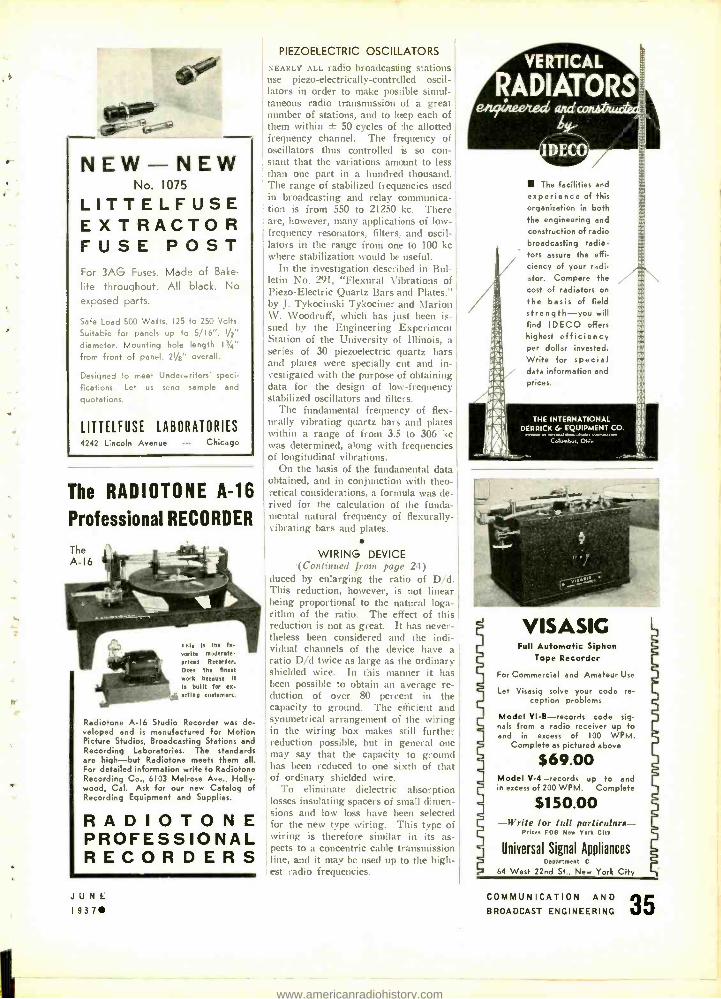
NEW -NEW No. 1075
LITTELFUSE EXTRACTOR FUSE POST i -or 3AG Fuses. Made of Bake -
I te throughout. All black. No
exposed parts.
,fe Load 500 Watts, 125 to 250 Volts.
suitable for panels up to 5/16 ". 1/2"
lameter. Mounting hole length 13/4"
'rom front of panel. 21/8" overall.
)esigned to meet Urderwriters' speci-
'cations. Let us send sample and
uotations.
LITTELFUSE LABORATORIES 4242 Lincoln Avenue - -- Chicago
The RADIOTONE A -16
Professional RECORDER
tom. this Is the
uorlte moderate priced Recorder.
Does the finest work because It
Is built for ex.
acting customers.
Radiotone A -I6 Studio Recorder was de- veloped and is manufactured for Motion Picture Studios, Broadcasting Stations and Recording Laboratories. The standards are high -but Radiotone meets them ell. For detailed information write to Radiotone Recording Co., 6103 Melrose Ave., Holly- wood, Cal. Ask for our new Catalog of Recording Equipment and Supplies.
RADIOTONE PROFESSIONAL RECORDERS
JUNE 1937
PIEZOELECTRIC OSCILLATORS
NEARLY ALL radio broadcasting stations use piezo- electrically -controlled oscil- lators in order to make possible simul- taneous radio transmission of a great number of stations, and to keep each of them within ± 50 cycles of the allotted frequency channel. The frequency of oscillators thus controlled is so con- stant that the variations amount to less than one part in a hundred thousand. The range of stabilized frequencies used in broadcasting and relay communica- tion is from 550 to 21250 kc. There are, however, many applications of low - frequency resonators, filters. and oscil- lators in the range from one to 100 kc where stabilization would be useful.
In the investigation described in Bul- letin No. 291, "Flexural Vibrations of Piezo- Electric Quartz Bars and Plates." by J. Tykocinski Tykociner and Marion W. Woodruff, which has just been is- sued by the Engineering Experiment Station of the University of Illinois. a series of 30 piezoelectric quartz bars and plates were specially cut and in- vestigated with the purpose of obtaining data for the design of low- frequency stabilized oscillators and filters.
The fundamental frequency of flex - urally vibrating quartz bars and plates within a range of from 3.5 to 306 kc was determined, along with frequencies of longitudinal vibrations.
On the basis of the fundamental data obtained, and in conjunction with theo- retical considerations, a formula was de- rived for the calculation of the funda- mental natural frequency of fiexurally- vibrating bars and plates.
WIRING DEVICE .(Continued front page 24)
duced by enlarging the ratio of D /d. This reduction, however, is not linear being proportional to the natural loga- rithm of the ratio. The effect of this reduction is not as great. It has never- theless been considered and the indi- vidual channels of the device have a ratio D/d twice as large as the ordinary shielded wire. In this manner it has been possible to obtain an average re- duction of over 80 percent in the capacity to ground. The efficient and symmetrical arrangement of the wiring in the wiring box makes still further reduction possible, but in general one may say that the capacity to ground has been reduced to one sixth of that of ordinary shielded wire.
To eliminate dielectric absorption losses insulating spacers of small dimen- sions and low loss have been selected for the new type wiring. This type of wiring is therefore similar in its as- pects to a concentric cable transmission line, and it may be used up to the high- est radio frequencies.
VERTICAL
RADIATORS
The facilities and
experience of this
organization in both the engineering and
construction of radio broadcasting radia - tors assure the effi- ciency of your radi- ator. Compare the
cost of radiators on
the basis of field strength -you will find IDECO offers highest efficiency per dollar invested. Write for special data information and
prices.
THE INTERNATIONAL DERRICK G EQUIPMENT CO.
Columbus, Okie
VISASIC Full Automatic Siphon
Tape Recorder
For Commercial and Amateur Use
Let Visasig solve your code re- ception problems
Model VI -B- records code sig- nals from a radio receiver up to and in excess of 100 WPM.
Complete as pictured above
$69.00 Model V-4 -records up to and in excess of 200 WPM. Complete
$150.00 -Write for full particulars -
Prices FOB New York City
Universal Signal Appliances Department C
64 West 22nd St., New York City
COMMUNICATION AND BROADCAST ENGINEERING
www.americanradiohistory.com
r
rr
RESISTANCE ENGINEERING GUIDE
. . . f!'PP, Complete resistor
information In the handiest possible form f o r engineers a n d
designers of electric and electronic equip - hernt - also other
lpful engineering information such as
power formulas. Ohm's law. sistor color code chart. etc., etc. Copy free to in- dustrial resistor users requesting it on Com-
pany stationery.
l",
INTERNATIONAL RESISTANCE COMPANY 401 NORTH BROAD STREET. PHILADELPHIA. PA.
Factories or L,e.n.... ;n Canada. Enrlana. r,.ne.. O...,..y. I,.IT. D.nm,s na A...t.a;, MAKERS Or RESISTANCE UNITS Of MOPE TYPES. IN MOUE SHAPES, FOR MOPE APPLICATIONS THAN ANY OTHER MANUFACTUIER IN THE WOULD
NEW . HIGH FREQUENCY AND ULTRA -HIGH FREQUENCY
PORTABLE TRANSMITTER TYPE HFM
We have helped many with their portable and mobile communication problems. Write, stating your require- ments, and we will advise on available or custom built
10 watts nominal oLtput over entire range. 7000 to 60,000 Kc. with single crystal. Lower frequencies fo or- der. Completely self -contained. AI, A2 and A3 emission. Operates from 6v. D.C. or 110 A.C. supply. Power equipment available for either. Anti -noise microphone for mobile operation. Portable receiving equip- ment fo work with above.
units.
PORTABLE PACK M.O.P.A. UNIT
TYPE PTR -19 -M
2 -WATT TRANSMITTER AND A RECEIVER -MONITOR write for Bulletin C -37
RADIO TRANSCEIVER LABS. 8627 - 115th Street
Richmond Hill New York
1937 JUNE
NEW
REMLER AP3-18 PORTABLE SPEECH INPUT
ENDORSED B Y L E A D I N G
BROADCAST
STATIONS High Gain
High Fidelity
Moderate Price
Compact. high fidelity audio system incorporating refine- ments ordinarily associated with studio equipment. High gain remote amplifier and power supply, designed for use with either dynamic, velocity or inductor microphone. Three chan- nel input, each controlled by individual ladder attenuators and wire wound tapped master gain potentiometer. Output feeds one or two broadcast loops simultaneously. 50, 200 or 250 ohm input as ordered. For operation with A.C. power supply shown or with battery boa. Units connected by 6 ft. cable with lock type plugs. Overall
all nglrl ain 93 db. Tubes: 2 -77 2-6A6 and l-60. Write for
catalog
REMLER COMPANY, Ltd. 2101 Bryant Street San Francisco
REMLER -THE RADIO FIRM AS OLD AS RADIO
HERE'S QUALITY THAT'S RUGGED
Public reaction proves there's a thousand times more satisfaction in qual- ity reproduction. The best way to get it is through the use of quality P.A. equipment.
AR-43, $75.00
Quality alone is worth the price, but quality and ruggedness as found in Brush crystal sound cell mikes has no limit of value.
Details on request. BR-2S. S37.50
The BRUSH DEVELOPMENT COMPANY 3317 PERKINS AVENUE CLEVELAND, OHIO
COMMUNICATION AND BROADCAST ENGINEERING
www.americanradiohistory.com
r
a
ONE SOURCE of SUPPLY BROADCASTING STATIONS - SOUND STUDIOS- LABORATORIES -ENGINEERS
We carry in stock -for immediate delivery -at whole- sale discounts -the following lines: ' rovoz Allen B. Dumont Struthers -Dunn Astatic Hammarlund Thordarson Aladdin I. R. C. Triplett Audak Leach United Transforms Bliley Littelfuse Weston Brush National Ward Leonard Cardwell Ohmite Yazley
Cinaudagraph Presto Recordir : And many others Cornell- Dubilier Sim ^ ̂ ^ { ,i s
R A D I O C O R P O R A T I O N
80 CORTLANDT ST., NEW YORK TERMINAL
Communication and Broadcast Engineering
Covering Radio Communication, Broadcasting, Police, Marine and Aeronautical Radio, Telephony
and Telegraphy, Facsimile and Television. Published monthly.
SUBSCRIPTION, $2.00 YEARLY (Foreign $3.00)
BRYAN DAVIS PUBLISHING CO., Inc. 19 East 47th Street New York. N. Y.
JUNE 1 937
YOU ARE
CORDIALLY INVITED
TO VIEW THE NEW
COLLINS
BROADCAST TRANSMITTERS
AND STUDIO EQUIPMENT
ON DISPLAY AT THE
NAB CONVENTION
COLLINS RADIO COMPANY
UHX -10 TRANSMITTER 1500- 60,000 KILOCYCLES
FIXED PORTABLE MOBILE
AC OR BATTERY POWERED
LOCAL AND REMOTE CONTROL MODELS
NOMINAL RATING 10 WATTS OUTPUT
COMPACT LIGHT RUGGED
WRITE FOR FULL DETAILS
HARVEY RADIO LABORATORIES, INC. Dept. C, 12 Boylston Street Brookline, Mass.
Expert: 25 Warren Street, New York City Cable: °Siniontriee"
COMMUNICATION AND
39 BROADCAST ENGINEERING
www.americanradiohistory.com
MICROPHONES
"V" SERIES
The all- feature microphone. Preferred sy
Discerning Broadcast, Sound and Con -
munication engineers the World ov,r. Three models from $35.00 to $75.00, 1st.
ELECTRO -VOICE MFG. CO., INC.
334 E. Colfax Ave. South Bend, Isl. Export Dep't.: 100 Varick St., New Yak
"K" SERIES
Genuine quality brought fo the low -price field. Three models from $19.50 to $29.50, list. Also a
Static -Velocity model at $20.00, list.
WRITE FOR CATALOGUE
AND FURTHER DETAILS
CARBON
Five popular car- bon models priced from $5.00 to $25.00, list. Complete re- pair service on all makes.
INSURE GOOD- UNINTERRUPTED BROADCASTING
IDEAL COMMUTATOR RESURFACER
Used extensively by broadcasting stations to insure good and neater- rioted radio reception. Rough Commutaton are smoothed up without dis- mantling motor. Nain - leina Commutators and Slip Rings at original efficiency. Used period - ically while machines are in service. Gristly lengthens the time be- tween major overhauling jobs. Serving 16,000 users. Sent ow ten -day free trial
-no money down. Ideal Csuatata Dosser Cs.
1062 Park Arelu, Sycamore, Mira.
EXPERIENCE -11 years of it -is our assurance that we can recondition your transmitting tuba properly and build in Long Life and Proper Characteristics.
Aircooled Tubes 100 to 1000 watts. Watercooled 5 to 36 KW. Satisfaction Guaranteed
NATIONAL RADIO TUBE CO., INC. 3421 16th STREET SAN FRANCISCO. CALIF.
QUARTZ CRYSTALS -all types LOW TEMPERATURE COEFFICIENTS
X and Y CUTS HOLDERS GROUND TO ANY PRACTICAL SPECIFICATIONS
Write for complete particulars BELLEFONTE RADIO & MFG. CO.
Bellefeate Pennsylvania
Precision Frequency Control Units MARINE
AIR CRAFT POLICE
WRITE US YOUR SPECIFICATIONS
MONITOR PIEZO PRODUCTS CO. 2802 West Avenue 32, Los Angeles, California
"THE CRYSTAL SPECIALISTS SINCE 192Sw
PIEZO- ELECTRIC CRYSTALS GUARANTEED Accurate to BETTER than .01%
SCIENTIFIC RADIO SERVICE Send for FREE Booklet and Price List!
UNIVERSITY PARK - - - - HYATTSVILLL, MD.
INDEX OF ADVERTISERS A
American Transformer Co 34 Amperes Electronic Products Co.
Second Cover Amperite Corp. Fourth Cover Audak Co. 32
B Bellefonte Radio & Mfg. Co 40 Bliley Electric Co 39 L. S. Brach Mtg. Cu 34 Brush Development Co 38
C
Cinaudagraph Corp. 2N
Clarostat Mfg. Co. 34 Collins Radio Co 39 Cornell- Dubiller Corp. 3
Electro-Voice Mfg. Co 40 Epiphone, Inc. 28
G
Gates Radio & Supply Co 33 General Radio Co Third Cover
II Harvey Radio Laboratories
Ideal Commutator Dresser Co International Derrick & Equipment
Co. International Resistance Co Isolantite, Inc.
I.
R
39 RCA Mfg. Co.. Inc 23 Radiotone Recording Co 35 Radio Transceiver Labs 38 Remler Co.. Ltd 38
40
35 38 25
Lear Developments. Inc 36 Littelfuse Laboratories
M
Monitor Plezo Products Co.
N
National Radio Tube Co
P
Presto Recording Corp
S
Scientific Radio Service 40 Shure Brothers Co 37 Sigma Instrumente, Inc 37 Sound Apparatus Co. 36 Swedish Iron & Steel Corp 29
35
Terminal Radio Co 39
40 U
United Electronics United Transformer Corp Universal Microphone Co., Ltd
40 Universal Signal Appliances
31 Western Electric .
R'
5 1
37 35
27
JUNE 1937
COMMUNICATION AND BROADCAST ENGINEERING
www.americanradiohistory.com
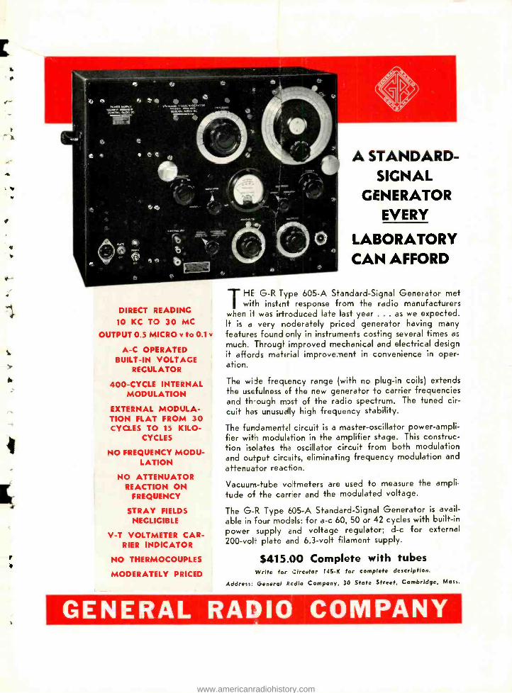
f
y
4
4
I
DIRECT READING
10 KC TO 30 MC
OUTPUT 0.5 MICRO v to 0.1 y
A -C OPERATED BUILT -IN VOLTAGE
REGULATOR
400 -CYCLE INTERNAL MODULATION
EXTERNAL MODULA- TION FLAT FROM 30 CYCLES TO 15 KILO-
CYCLES
NO FREQUENCY MODU- LATION
NO ATTENUATOR REACTION ON
FREQUENCY
STRAY FIELDS NEGLIGIBLE
V -T VOLTMETER CAR- RIER INDICATOR
NO THERMOCOUPLES
MODERATELY PRICED
A STANDARD - SIGNAL
GENERATOR EVERY
LABORATORY CAN AFFORD
THE G -R Type 605 -A Standard -Signal Generator met with instent response from the radio manufacturers
when if was irtroduced late last year . .. as we expected. It is a very noderately priced generator having many features found only in instruments costing several times as
much. Througi improved mechanical and electrical design it affords material improvement in convenience in oper- ation.
The wide frequency range (with no plug -in coils) extends the usefulness of the new generator to carrier frequencies and th -ough mDst of the radio spectrum. The tuned cir- cuit has unusually high frequency stability.
The fundamental circuit is a master -oscillator power- ampli- fier wit, modulation in the amplifier stage. This construc- tion isolates tha oscillator circuit from both modulation and output circuits, eliminating frequency modulation and
attenuator reaction.
Vacuum -tube votmeters are used to measure the ampli-
tude of the carrer and the modulated voltage.
The G -R Type 605 -A Standard -Signal Generator is avail- able in four modals: for a -c 60, 50 or 42 cycles with built -in
power supply and voltage regulator; d -c for external 200 -volT plate and 6.3 -volt filament supply.
$415.00 Complete with tubes Write for Circular 145 -K for complete description.
Address: General Rcdio Company, 30 State Street, Cambridge, Mass.
GENERAL RADIO COMPANY
www.americanradiohistory.com
A MPERI TE VELOCI T9
The remarlebh success of the Amperite Velocity is the result of imperites P.A. Policy -to give P.A. Men the fin. rpossible microphones at prices no higher than wiat they would pay for other mikes. A letter from .ìidley's T.A. Systems is typical of the general response of the P.A. industry. It says: , "Your Veloc.V is the finest type of microphone 1
have ever end.... Pease duplicate my order.'"
You, too, wiliuplicate crders ... improve installa- tions ... and snjoy bet Q quality at a competitive price by usi.g Ampe-Le Velocity Microphones.
There's a I-Ddel for c very type of installation.
COD:ULT YOU3 JOBBER NOW!
NEW! Desk Stand New and novel. Ideal f.: desk, pulpit, footlights, banque. Mic. rophone can be rotated in ,se hor-
izontal plane. and used in arions positions- as desired. LEAF SPRING SUSPENSION A= AS AN EXTRA SHOCK AB; M :1ER.
Unusually stable. STAND ONLY. S4.00 LIST. Name plate vi r max- imum of 10 letters. $2.00 L ST.
NEW! "Ham Mike" No peaks! No splashing! Real broadcast quality. Output. -68 db. RF Choke Cir- cuit included in microphone. Operates directly into grid of tube. Rugged. Not affected by temperature or pressure changes MODEL HAM (high imped- J MODEL HAL 1200 ohms),..
$22.00 LIST
dudes new special Ham Desk Stand. call letters, and 6 feet of cable.
MPERITE JUNIOR "lapel- Velocity of surpassing
. , Size of a match lectures and sped
hidden under .. .
. t with any . Transformer one
: or
act Outp lion of cluded
MODEL 71
71-if (2000 oh ' S
FREE WINDOW DECAL adver- tising your : ound Service. Size 54tx9' , finished in 4
striking coos. WINDOW DISPLAY,
I1 x l:, and .... New illustrated bulletins. Write for tsetse valuable
sales : rips today.
' RITE LIST
very high ite stand -
h and music peaks. Flat
range. Output. ded. Fitted with
nd swivel bracket. ohms) with 8 ft. of
RAH (2000 ohms) high with 12 ft of coblr
AMPER/TE C 51) BROAL' "NAY, N. Y. U.S.A. Cable Address: Alkem, New York
A -
r
www.americanradiohistory.com