Engineering Drawing Notes - Course Websites · drawing numbers or catalog numbers, ... of sight. A...
92
Engineering Drawing Notes Part A - 2D Drawing Principles ME170 Computer Aided Design Instructor: Mike Philpott Emeritus Associate Professor of Mechanical & Industrial Engineering
-
Upload
trinhnguyet -
Category
Documents
-
view
213 -
download
0
Transcript of Engineering Drawing Notes - Course Websites · drawing numbers or catalog numbers, ... of sight. A...
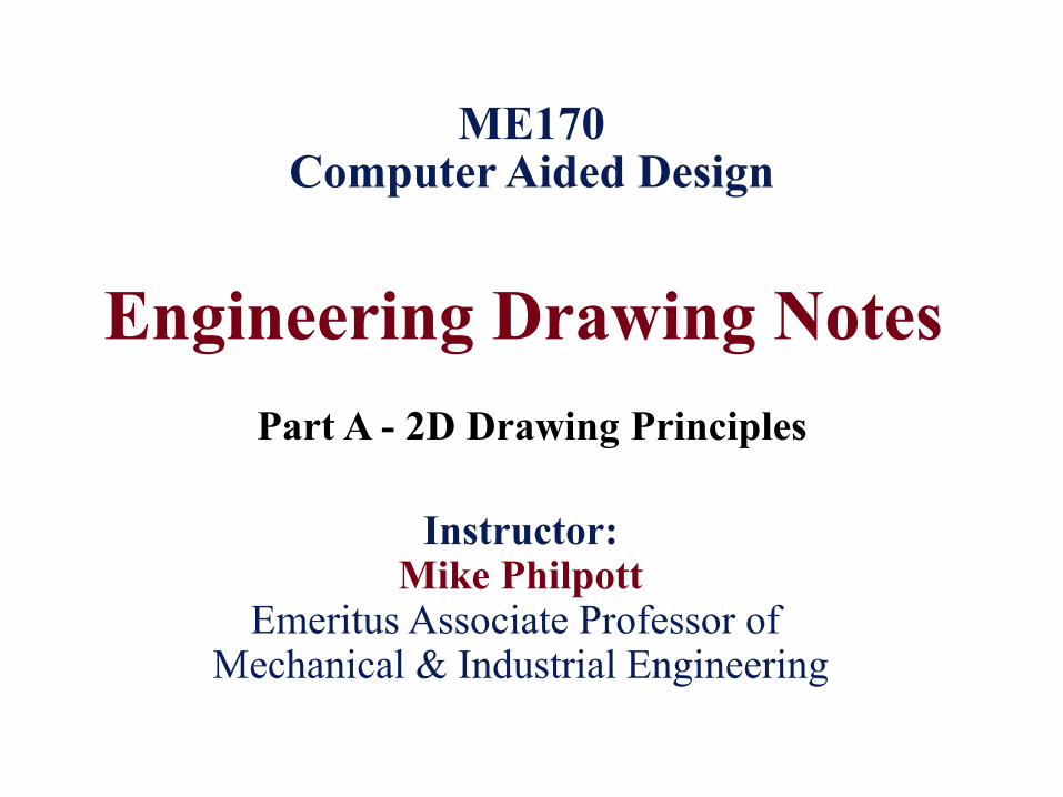
Engineering Drawing Notes
Part A - 2D Drawing Principles
ME170 Computer Aided Design
Instructor: Mike Philpott
Emeritus Associate Professor of Mechanical & Industrial Engineering
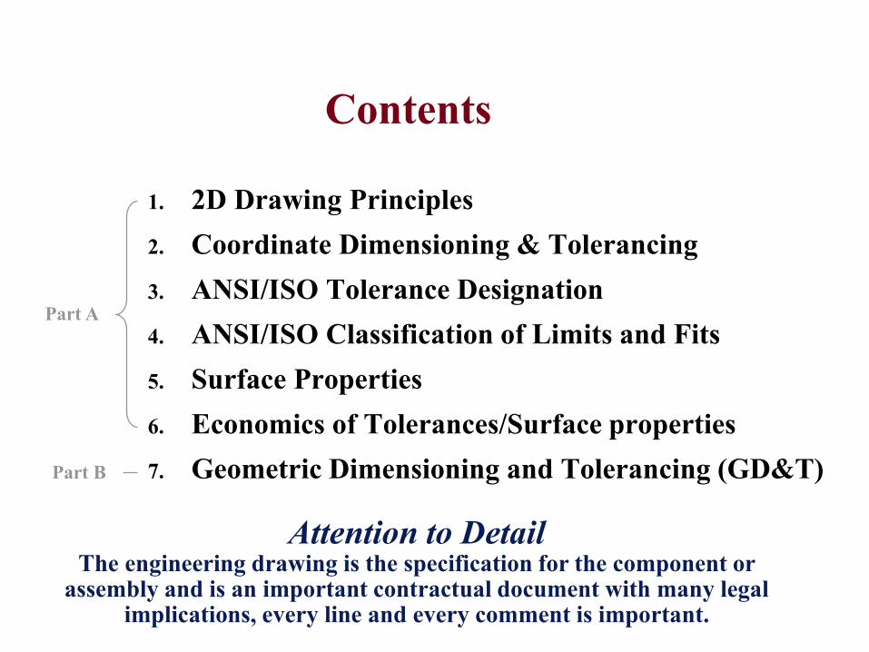
Contents
1. 2D Drawing Principles
2. Coordinate Dimensioning & Tolerancing
3. ANSI/ISO Tolerance Designation
4. ANSI/ISO Classification of Limits and Fits
5. Surface Properties
6. Economics of Tolerances/Surface properties
7. Geometric Dimensioning and Tolerancing (GD&T)
Attention to DetailThe engineering drawing is the specification for the component or
assembly and is an important contractual document with many legal implications, every line and every comment is important.
Part A
Part B
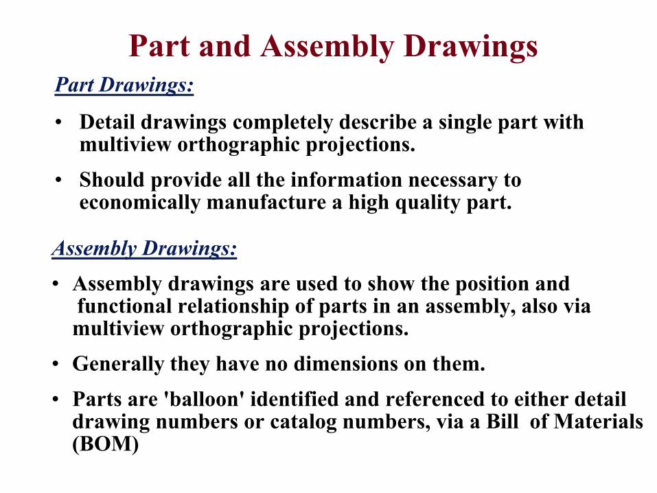
Part and Assembly Drawings
Assembly Drawings:
• Assembly drawings are used to show the position and functional relationship of parts in an assembly, also via multiview orthographic projections.
• Generally they have no dimensions on them.
• Parts are 'balloon' identified and referenced to either detail drawing numbers or catalog numbers, via a Bill of Materials (BOM)
Part Drawings:
• Detail drawings completely describe a single part with multiview orthographic projections.
• Should provide all the information necessary to economically manufacture a high quality part.
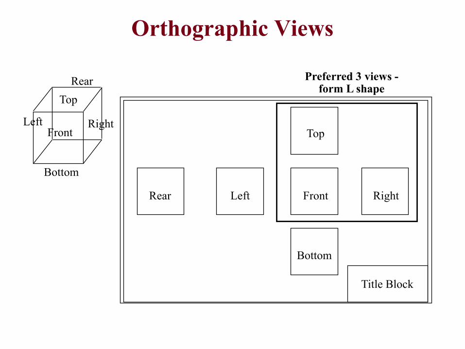
Orthographic Views
Title Block
Rear RightLeft Front
Top
Bottom
Front
Top
Left
Rear
Right
Bottom
Preferred 3 views -form L shape
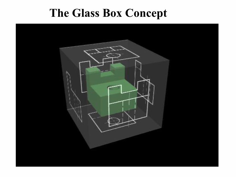
The Glass Box Concept
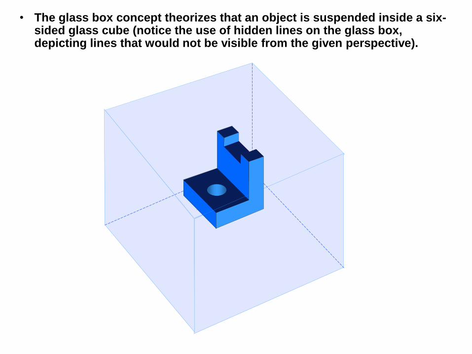
• The glass box concept theorizes that an object is suspended inside a six-sided glass cube (notice the use of hidden lines on the glass box, depicting lines that would not be visible from the given perspective).
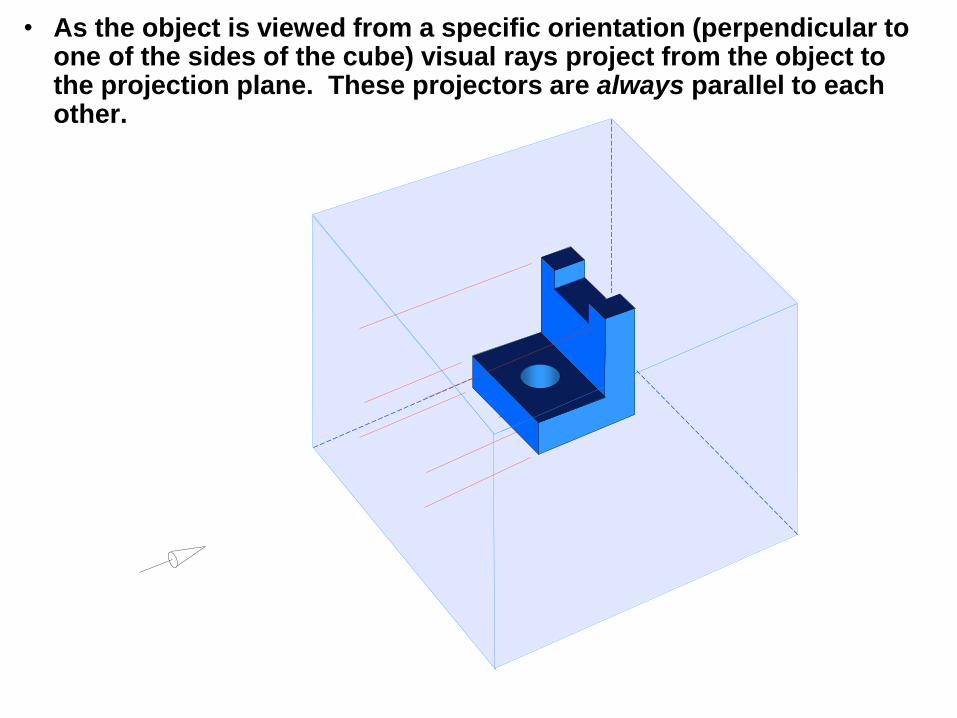
• As the object is viewed from a specific orientation (perpendicular to one of the sides of the cube) visual rays project from the object to the projection plane. These projectors are always parallel to each other.
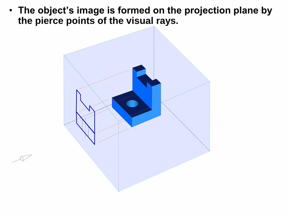
• The object’s image is formed on the projection plane by the pierce points of the visual rays.
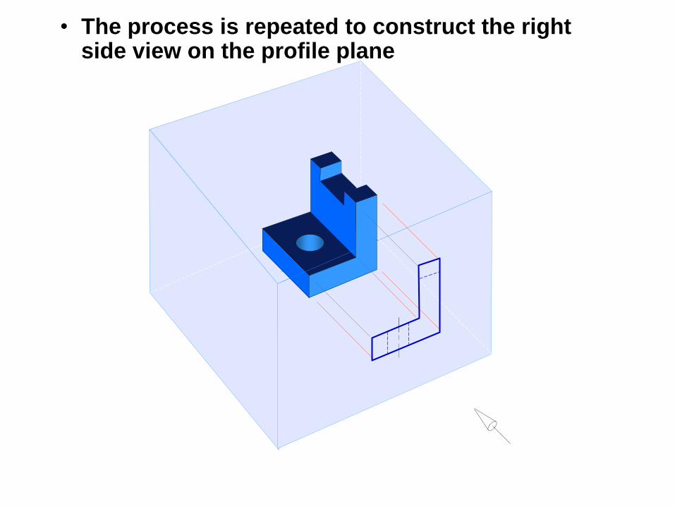
• The process is repeated to construct the right side view on the profile plane
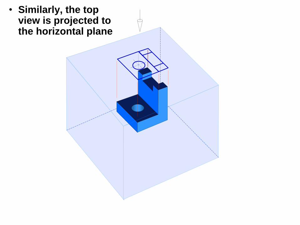
• Similarly, the top view is projected to the horizontal plane
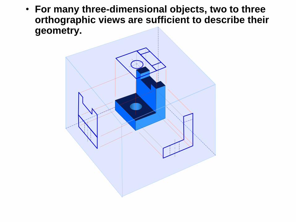
• For many three-dimensional objects, two to three orthographic views are sufficient to describe their geometry.
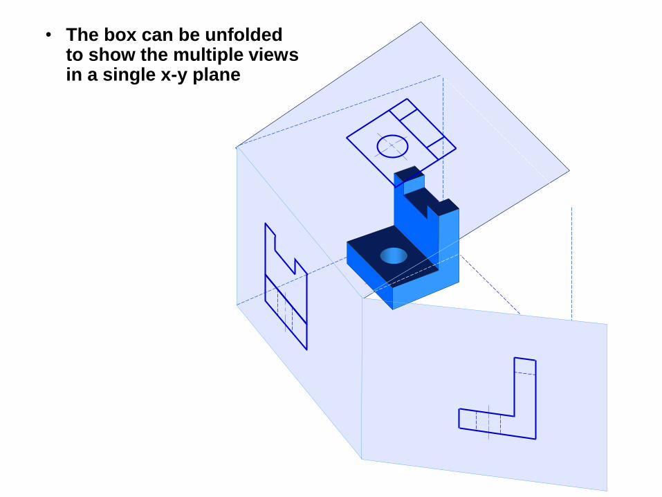
• The box can be unfolded to show the multiple views in a single x-y plane
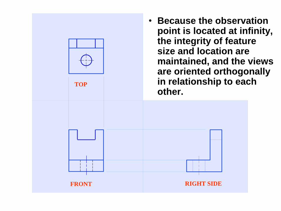
FRONT
TOP
RIGHT SIDE
• Because the observation point is located at infinity, the integrity of feature size and location are maintained, and the views are oriented orthogonally in relationship to each other.
FRONT
TOP
RIGHT SIDE
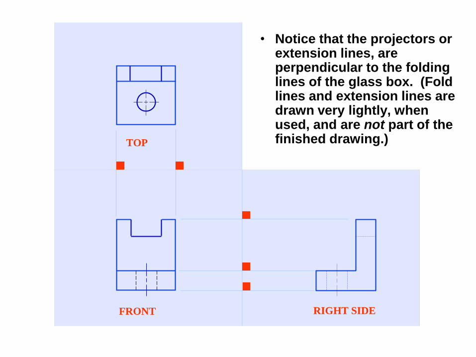
• Notice that the projectors or extension lines, are perpendicular to the folding lines of the glass box. (Fold lines and extension lines are drawn very lightly, when used, and are not part of the finished drawing.)
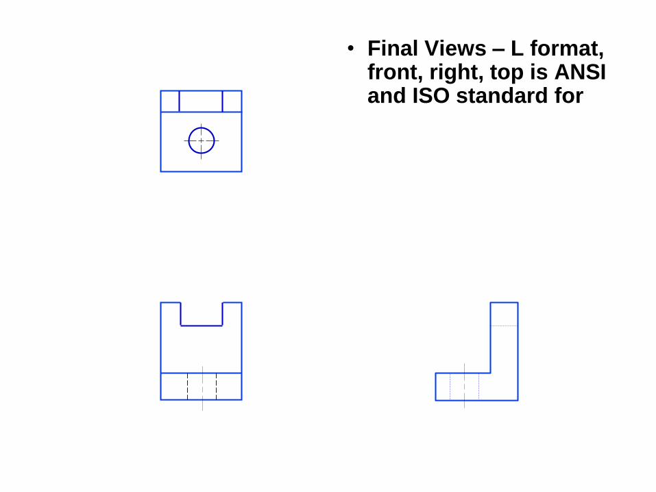
• Final Views – L format, front, right, top is ANSI and ISO standard for
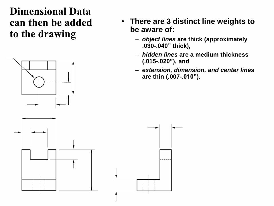
Dimensional Data can then be added to the drawing
• There are 3 distinct line weights to be aware of:
– object lines are thick (approximately .030-.040” thick),
– hidden lines are a medium thickness (.015-.020”), and
– extension, dimension, and center linesare thin (.007-.010”).
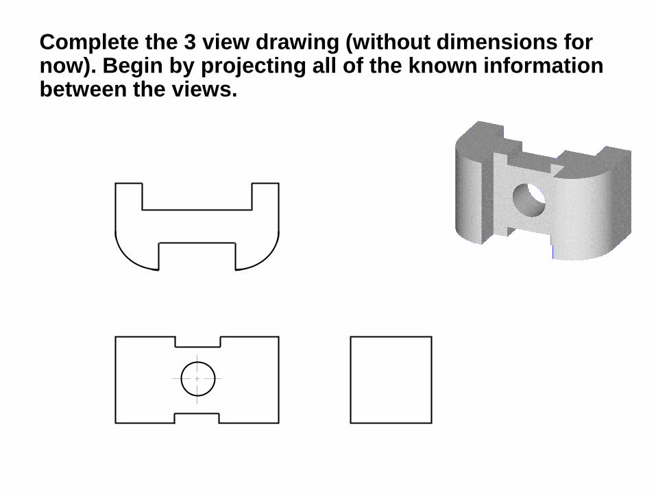
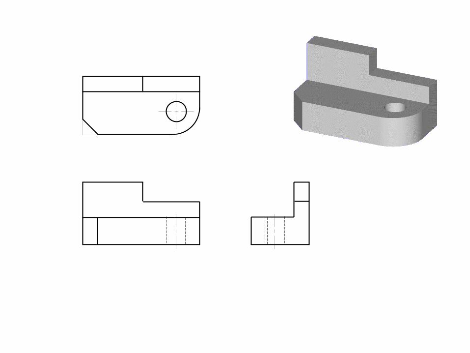
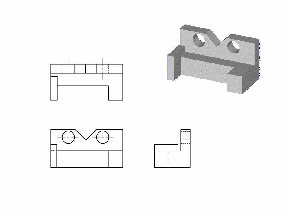
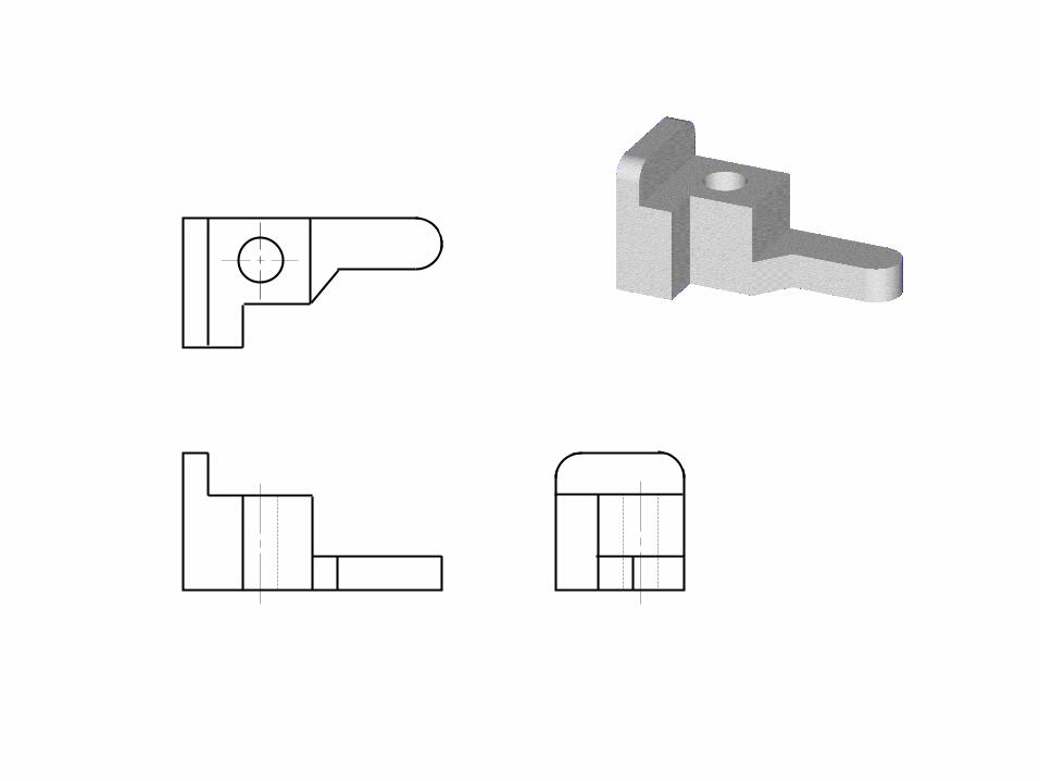
Complete the 3 view drawing (without dimensions for now). Begin by projecting all of the known information between the views.
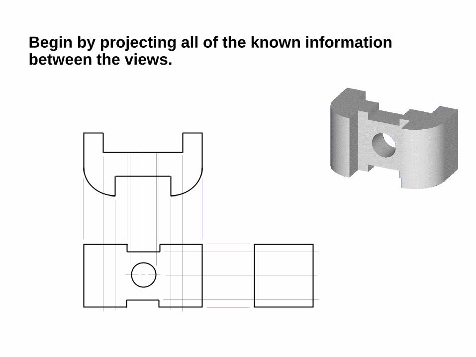
Begin by projecting all of the known information between the views.
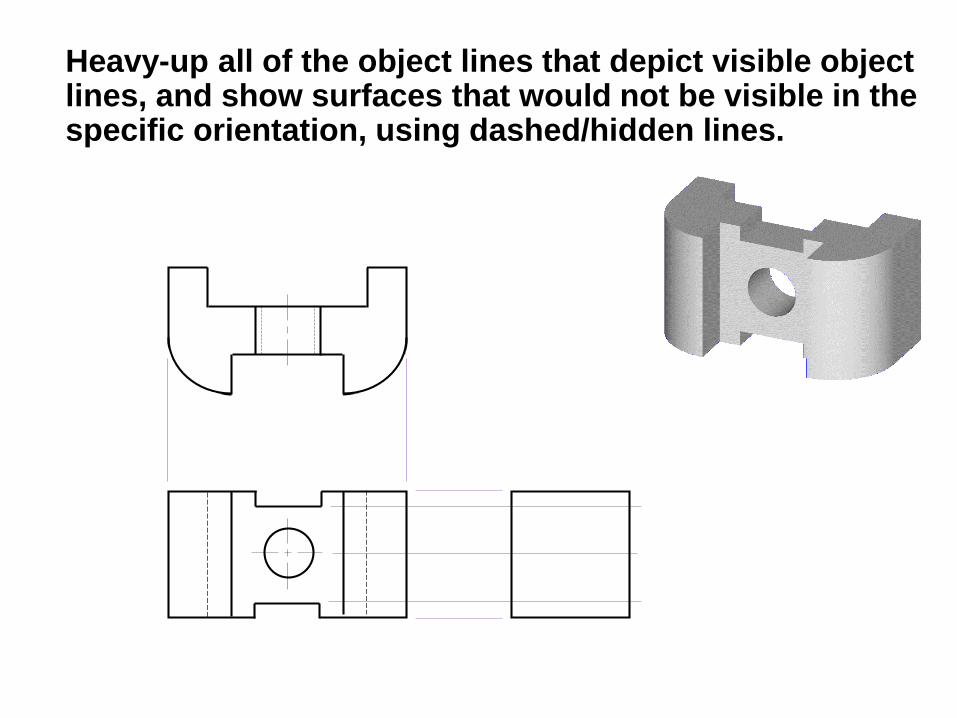
Heavy-up all of the object lines that depict visible object lines, and show surfaces that would not be visible in the specific orientation, using dashed/hidden lines.
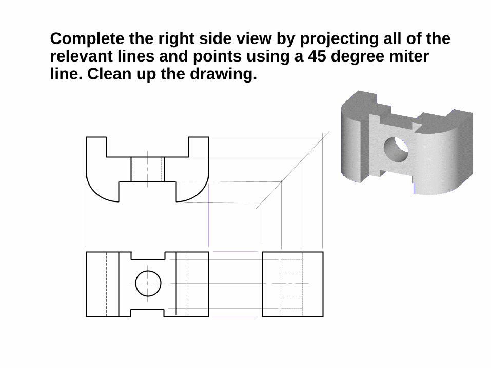
Complete the right side view by projecting all of the relevant lines and points using a 45 degree miter line. Clean up the drawing.
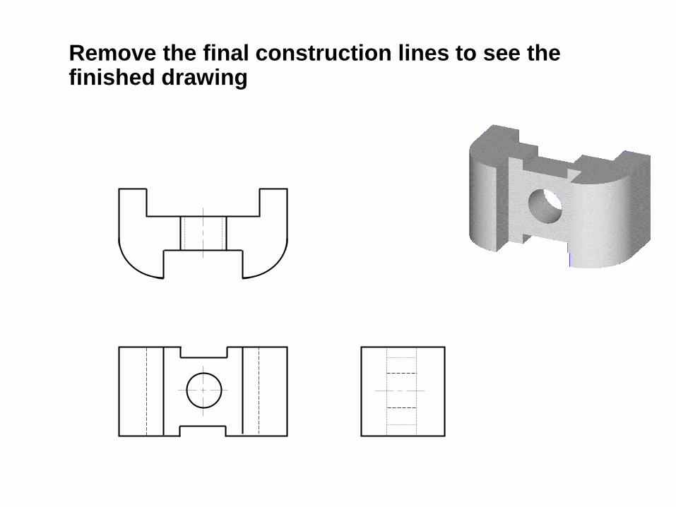
Remove the final construction lines to see the finished drawing
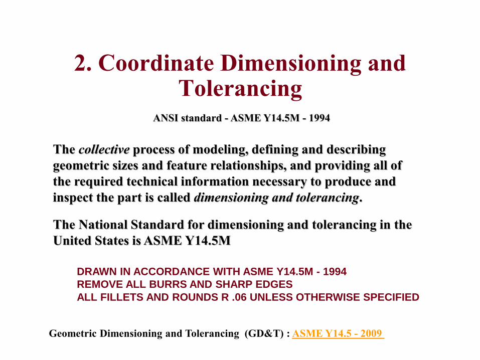
2. Coordinate Dimensioning and Tolerancing
The collective process of modeling, defining and describing
geometric sizes and feature relationships, and providing all of
the required technical information necessary to produce and
inspect the part is called dimensioning and tolerancing.
The National Standard for dimensioning and tolerancing in the
United States is ASME Y14.5M
DRAWN IN ACCORDANCE WITH ASME Y14.5M - 1994
REMOVE ALL BURRS AND SHARP EDGES
ALL FILLETS AND ROUNDS R .06 UNLESS OTHERWISE SPECIFIED
Geometric Dimensioning and Tolerancing (GD&T) : ASME Y14.5 - 2009
ANSI standard - ASME Y14.5M - 1994
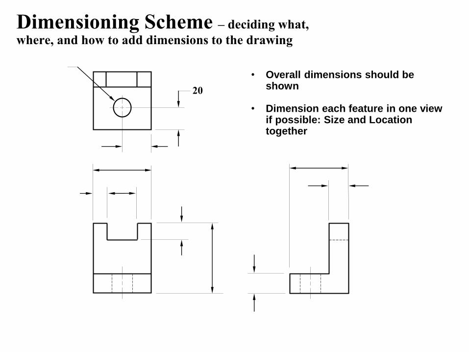
Dimensioning Scheme – deciding what,
where, and how to add dimensions to the drawing
20
• Overall dimensions should be shown
• Dimension each feature in one view if possible: Size and Location together
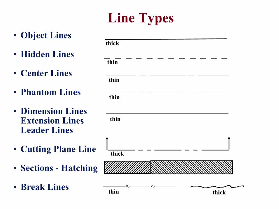
Line Types
• Object Lines
• Hidden Lines
• Center Lines
• Phantom Lines
• Dimension LinesExtension LinesLeader Lines
• Cutting Plane Line
• Sections - Hatching
• Break Lines
thin
thin
thin
thick
thin
thin
thick
thick
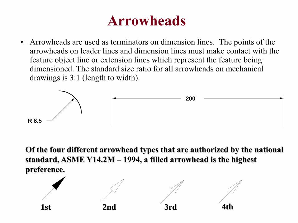
Arrowheads
• Arrowheads are used as terminators on dimension lines. The points of the arrowheads on leader lines and dimension lines must make contact with the feature object line or extension lines which represent the feature being dimensioned. The standard size ratio for all arrowheads on mechanical drawings is 3:1 (length to width).
200
R 8.5
1st 2nd 3rd 4th
Of the four different arrowhead types that are authorized by the national
standard, ASME Y14.2M – 1994, a filled arrowhead is the highest
preference.
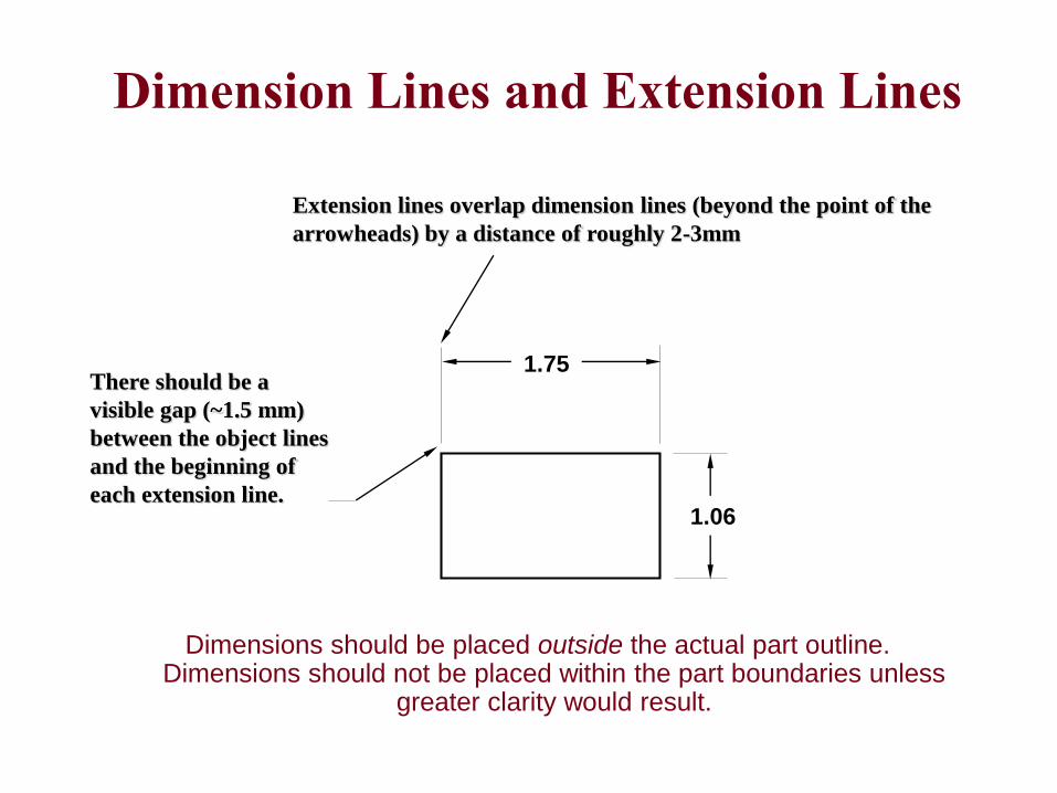
Dimensions should be placed outside the actual part outline. Dimensions should not be placed within the part boundaries unless
greater clarity would result.
There should be a
visible gap (~1.5 mm)
between the object lines
and the beginning of
each extension line.
Extension lines overlap dimension lines (beyond the point of the
arrowheads) by a distance of roughly 2-3mm
1.75
1.06
Dimension Lines and Extension Lines
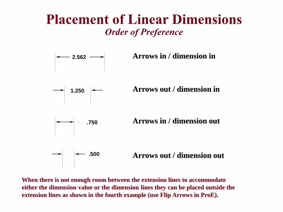
Arrows in / dimension in
Arrows out / dimension in
Arrows in / dimension out
Arrows out / dimension out
2.562
1.250
.750
.500
Placement of Linear DimensionsOrder of Preference
When there is not enough room between the extension lines to accommodate
either the dimension value or the dimension lines they can be placed outside the
extension lines as shown in the fourth example (use Flip Arrows in ProE).
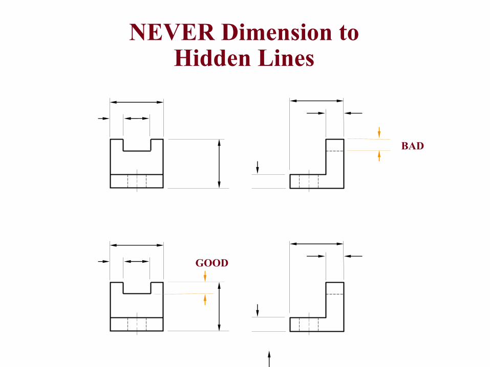
NEVER Dimension to Hidden Lines
BAD
GOOD
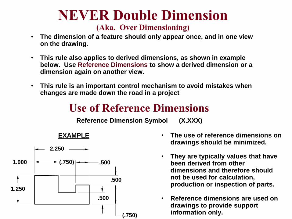
Reference Dimension Symbol (X.XXX)
• The use of reference dimensions on drawings should be minimized.
• They are typically values that have been derived from other dimensions and therefore should not be used for calculation, production or inspection of parts.
• Reference dimensions are used on drawings to provide support information only.
EXAMPLE
2.250
1.000 (.750) .500
1.250
.500
(.750)
.500
Use of Reference Dimensions
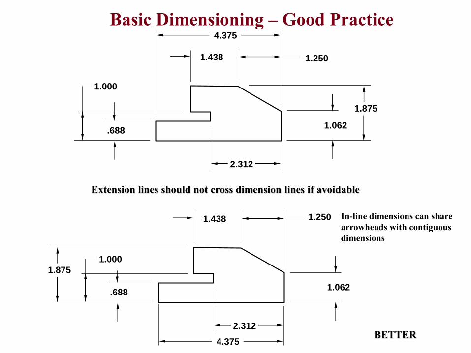
NEVER Double Dimension(Aka. Over Dimensioning)
• The dimension of a feature should only appear once, and in one view on the drawing.
• This rule also applies to derived dimensions, as shown in example below. Use Reference Dimensions to show a derived dimension or a dimension again on another view.
• This rule is an important control mechanism to avoid mistakes when changes are made down the road in a project
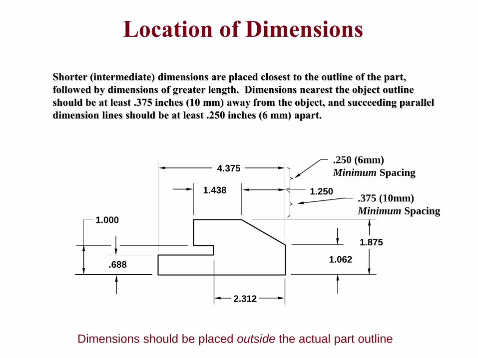
4.375
1.2501.438
1.062.688
1.000
1.875
2.312
.375 (10mm)
Minimum Spacing
.250 (6mm)
Minimum Spacing
Shorter (intermediate) dimensions are placed closest to the outline of the part,
followed by dimensions of greater length. Dimensions nearest the object outline
should be at least .375 inches (10 mm) away from the object, and succeeding parallel
dimension lines should be at least .250 inches (6 mm) apart.
Location of Dimensions
Dimensions should be placed outside the actual part outline
4.375
1.062.688
1.000
1.875
2.312
1.2501.438
4.375
1.062.688
1.000
2.312
1.2501.438
Extension lines should not cross dimension lines if avoidable
BETTER
Basic Dimensioning – Good Practice
In-line dimensions can share
arrowheads with contiguous
dimensions
1.875
1.375
1.375
.625 THRU
.250
.62
.250
x .62 DP
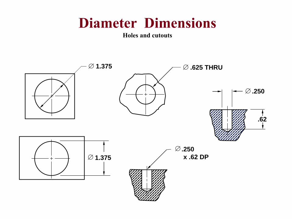
Diameter DimensionsHoles and cutouts
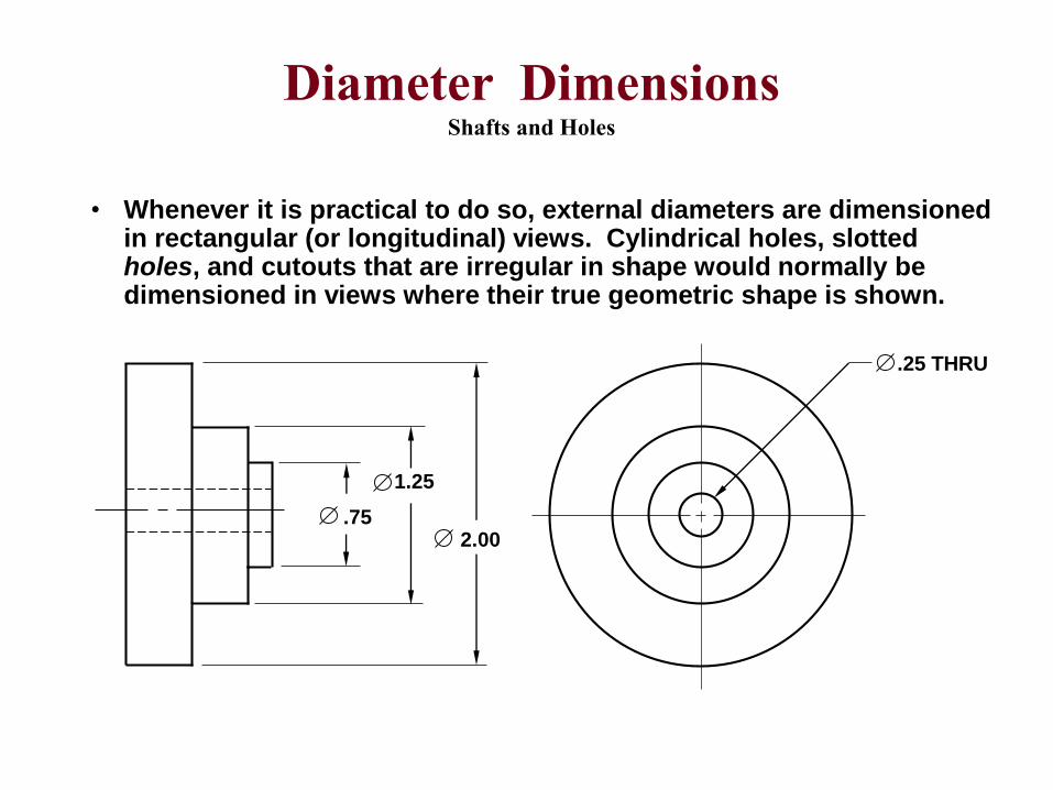
• Whenever it is practical to do so, external diameters are dimensioned in rectangular (or longitudinal) views. Cylindrical holes, slotted holes, and cutouts that are irregular in shape would normally be dimensioned in views where their true geometric shape is shown.
.75
1.25
2.00
.25 THRU
Diameter DimensionsShafts and Holes
18º 18º
18º
18º
18º
18º
3.50
.875
3X .562
6X .188
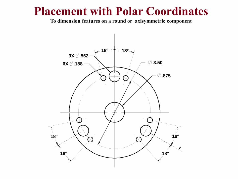
Placement with Polar CoordinatesTo dimension features on a round or axisymmetric component
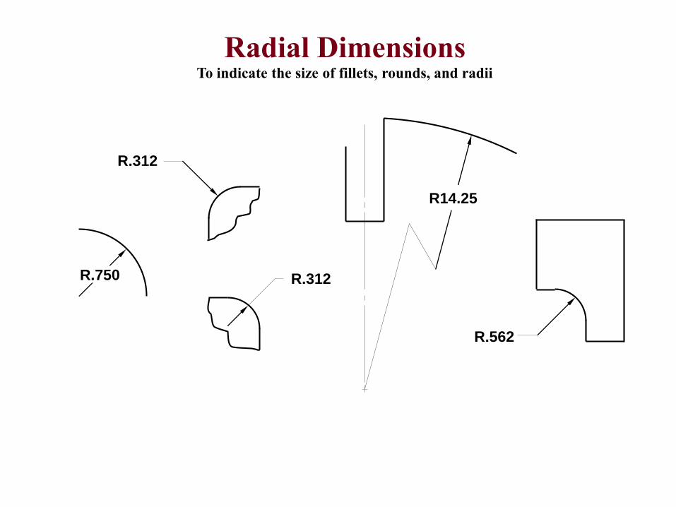
Radial DimensionsTo indicate the size of fillets, rounds, and radii
R.562
R.750 R.312
R.312
R14.25
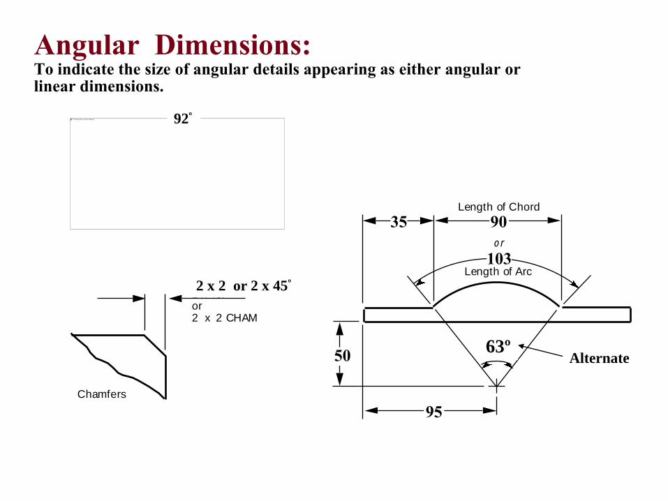
Angular Dimensions:To indicate the size of angular details appearing as either angular or linear dimensions.
63Þ
or
103
95
50
35 90Length of Chord
or
Length of Arc
2 x 45Þ or 2 x 2 CHAM
Chamfers
92º
2 x 2 or 2 x 45º
63ºAlternate
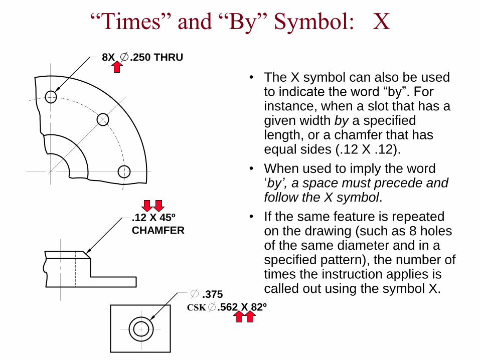
“Times” and “By” Symbol: X
• The X symbol can also be used to indicate the word “by”. For instance, when a slot that has a given width by a specified length, or a chamfer that has equal sides (.12 X .12).
• When used to imply the word ‘by’, a space must precede and follow the X symbol.
• If the same feature is repeated on the drawing (such as 8 holes of the same diameter and in a specified pattern), the number of times the instruction applies is called out using the symbol X.
.12 X 45º
CHAMFER
.375
.562 X 82ºCSK
8X .250 THRU
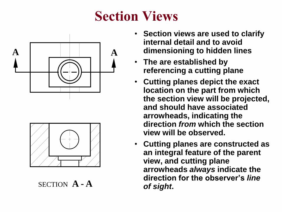
Section Views• Section views are used to clarify
internal detail and to avoid dimensioning to hidden lines
• The are established by referencing a cutting plane
• Cutting planes depict the exact location on the part from which the section view will be projected, and should have associated arrowheads, indicating the direction from which the section view will be observed.
• Cutting planes are constructed as an integral feature of the parent view, and cutting plane arrowheads always indicate the direction for the observer’s line of sight.
A A
SECTION A - A
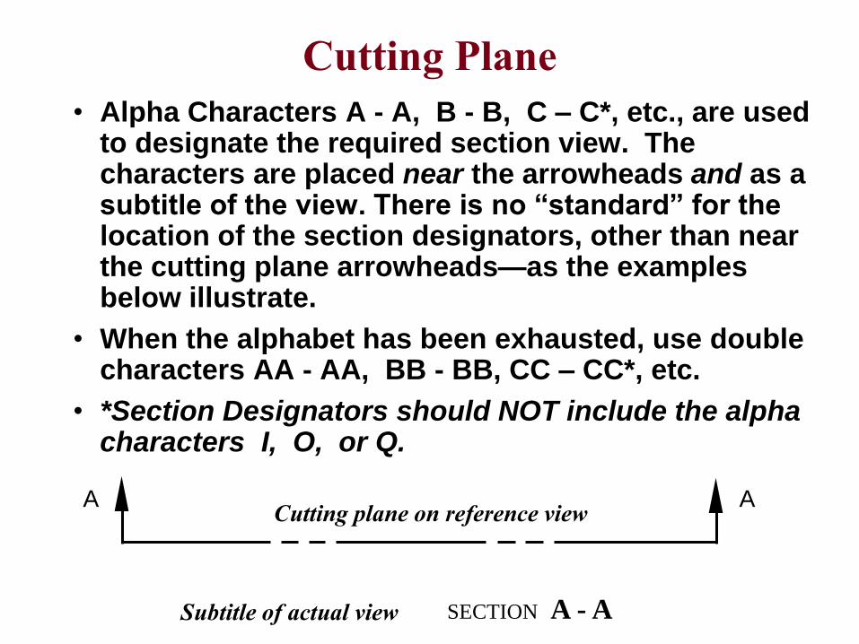
• Alpha Characters A - A, B - B, C – C*, etc., are used to designate the required section view. The characters are placed near the arrowheads and as a subtitle of the view. There is no “standard” for the location of the section designators, other than near the cutting plane arrowheads—as the examples below illustrate.
• When the alphabet has been exhausted, use double characters AA - AA, BB - BB, CC – CC*, etc.
• *Section Designators should NOT include the alpha characters I, O, or Q.
A A
SECTION A - A
Cutting Plane
Subtitle of actual view
Cutting plane on reference view
Crosshatching Section Views
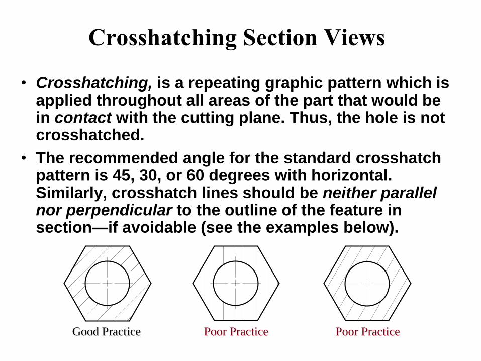
• Crosshatching, is a repeating graphic pattern which is applied throughout all areas of the part that would be in contact with the cutting plane. Thus, the hole is not crosshatched.
• The recommended angle for the standard crosshatch pattern is 45, 30, or 60 degrees with horizontal. Similarly, crosshatch lines should be neither parallel nor perpendicular to the outline of the feature in section—if avoidable (see the examples below).
Good Practice Poor Practice Poor Practice
• The general purpose cross hatch is used in most
individual detail component drawings and in
assembly applications where no confusion will
result.
• Each of the assembled components are depicted
with a different crosshatch angle to assist in part
differentiation.
• Specific crosshatch symbols are sometimes used
to represent each different material type.
Cross Hatch Standards
Cross Hatch Symbols
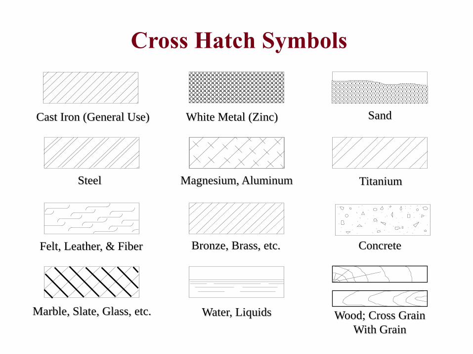
Cast Iron (General Use) White Metal (Zinc) Sand
Steel Magnesium, Aluminum Titanium
Marble, Slate, Glass, etc. Water, Liquids Wood; Cross Grain
With Grain
Felt, Leather, & Fiber Bronze, Brass, etc. Concrete
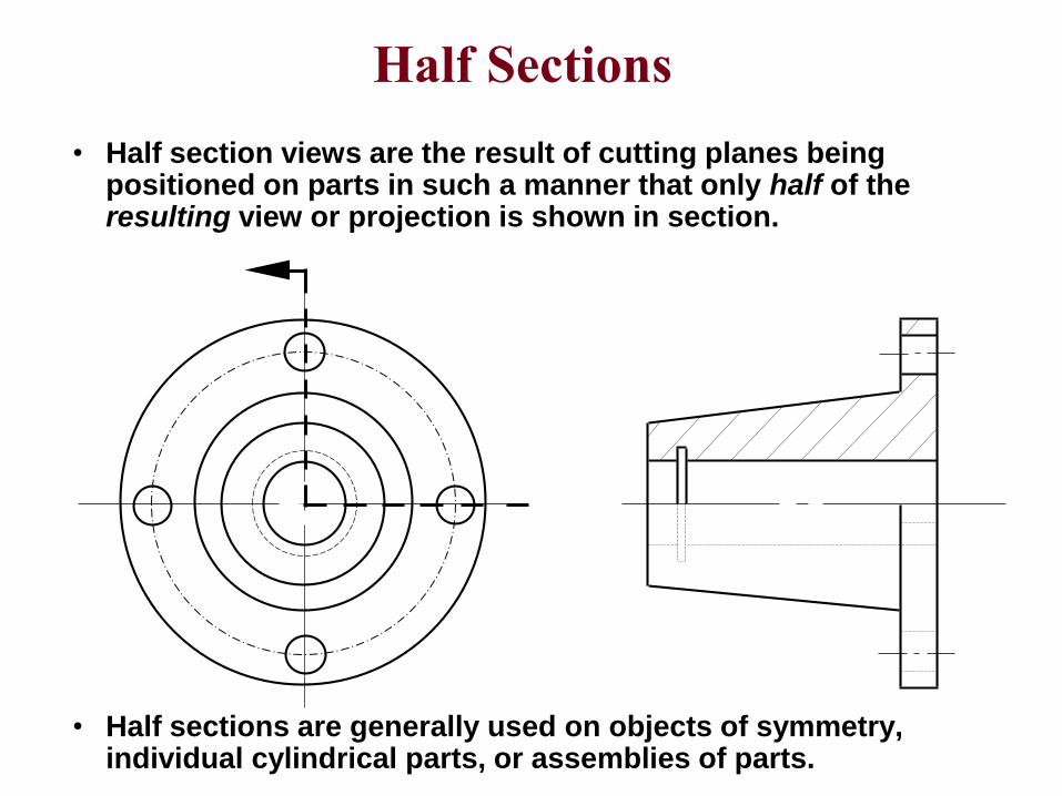
Half Sections
• Half section views are the result of cutting planes being positioned on parts in such a manner that only half of the resulting view or projection is shown in section.
• Half sections are generally used on objects of symmetry, individual cylindrical parts, or assemblies of parts.
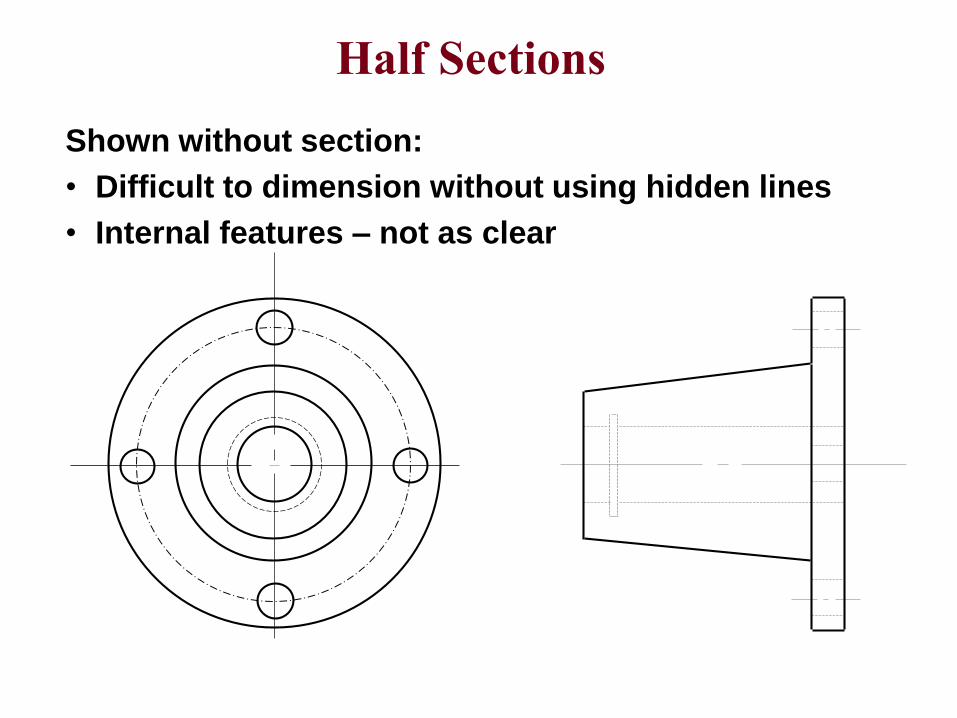
Half Sections
Shown without section:
• Difficult to dimension without using hidden lines
• Internal features – not as clear
D
D
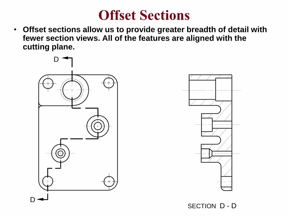
Offset Sections• Offset sections allow us to provide greater breadth of detail with
fewer section views. All of the features are aligned with the cutting plane.
SECTION D - D
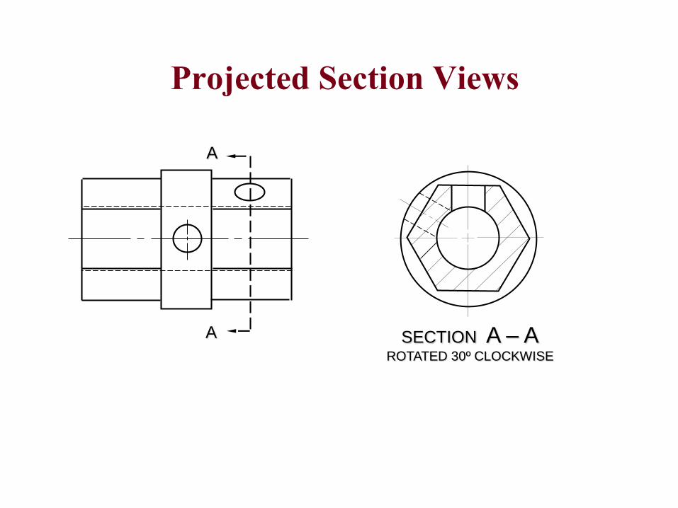
A
A SECTION A – AROTATED 30º CLOCKWISE
Projected Section Views

Drawing Notes
DRAWN IN ACCORDANCE WITH ASME Y14.5M - 1994
REMOVE ALL BURRS AND SHARP EDGES
ALL FILLETS AND ROUNDS R .06 UNLESS OTHERWISE SPECIFIED
Notes should be concise and specific. They should use
appropriate technical language, and be complete and accurate in
every detail. They should be authored in such a way as to have
only one possible interpretation.
General Notes
Local Notes 4X 8.20 M10 X 1.25
82º CSK 10
1.5 X 45º CHAM
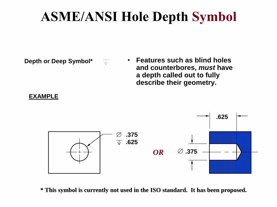
Depth or Deep Symbol*
* This symbol is currently not used in the ISO standard. It has been proposed.
.375
.625
EXAMPLE
.375
.625
OR
ASME/ANSI Hole Depth Symbol
• Features such as blind holes and counterbores, must have a depth called out to fully describe their geometry.
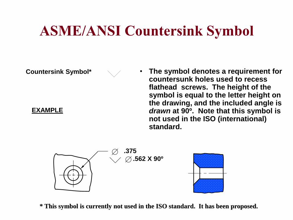
Countersink Symbol*
ASME/ANSI Countersink Symbol
• The symbol denotes a requirement for countersunk holes used to recess flathead screws. The height of the symbol is equal to the letter height on the drawing, and the included angle is drawn at 90º. Note that this symbol is not used in the ISO (international) standard.
* This symbol is currently not used in the ISO standard. It has been proposed.
.375
.562 X 90º
EXAMPLE
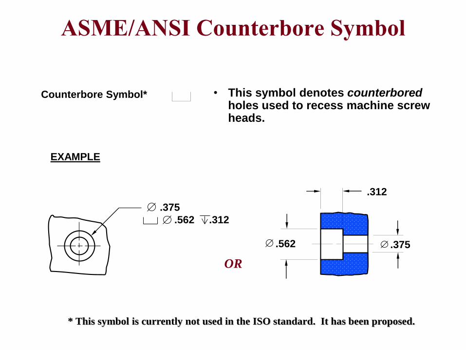
Counterbore Symbol* • This symbol denotes counterboredholes used to recess machine screw heads.
* This symbol is currently not used in the ISO standard. It has been proposed.
EXAMPLE
.375
.562 .312
.562
.312
.375
OR
ASME/ANSI Counterbore Symbol
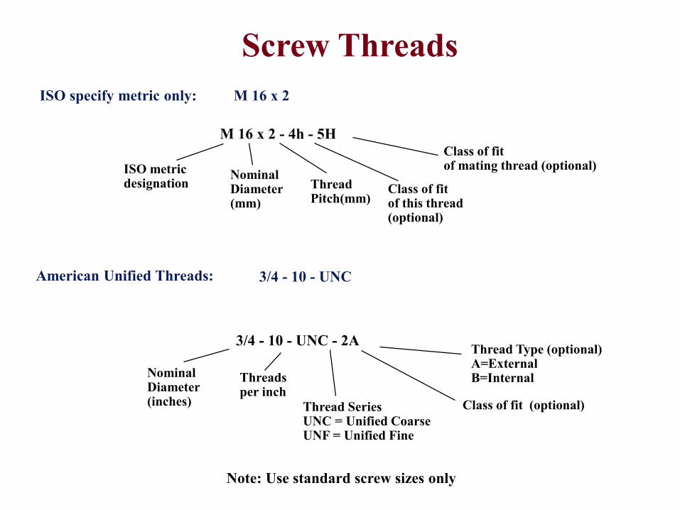
ISO specify metric only:
Note: Use standard screw sizes only
M 16 x 2 - 4h - 5H
ISO metric designation
Nominal Diameter(mm)
Thread Pitch(mm)
Class of fit of this thread(optional)
Class of fit of mating thread (optional)
American Unified Threads:
3/4 - 10 - UNC - 2A
Nominal Diameter(inches)
Threads per inch
Class of fit (optional) Thread SeriesUNC = Unified CoarseUNF = Unified Fine
Thread Type (optional)A=ExternalB=Internal
Screw Threads
M 16 x 2
3/4 - 10 - UNC
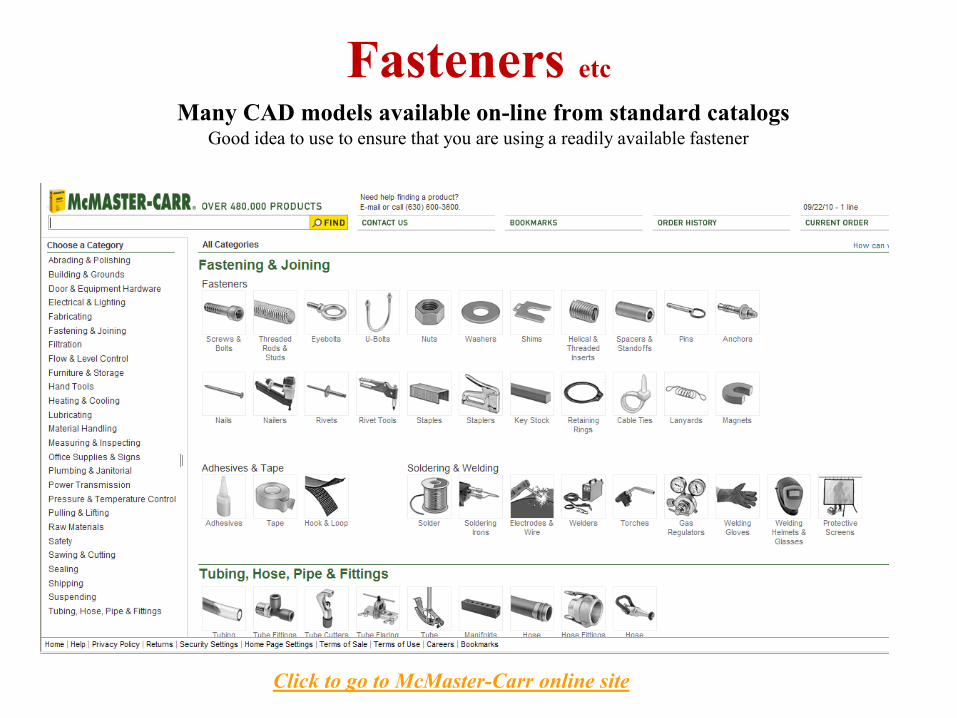
Fasteners etc
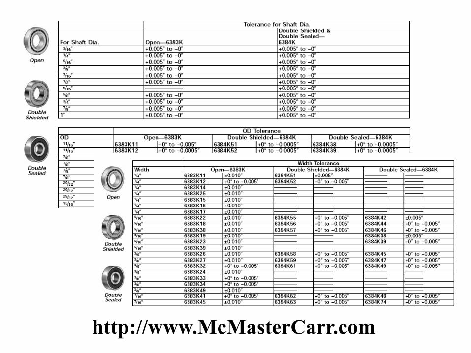
Many CAD models available on-line from standard catalogsGood idea to use to ensure that you are using a readily available fastener
Click to go to McMaster-Carr online site
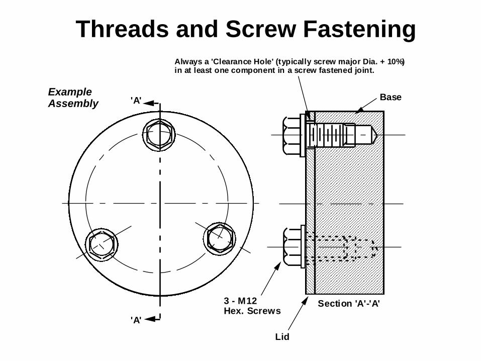
Threads and Screw Fastening
Example Assembly 'A'
'A'
Section 'A'-'A'3 - M12 Hex. Screws
Lid
Base
Always a 'Clearance Hole' (typically screw major Dia. + 10%) in at least one component in a screw fastened joint.
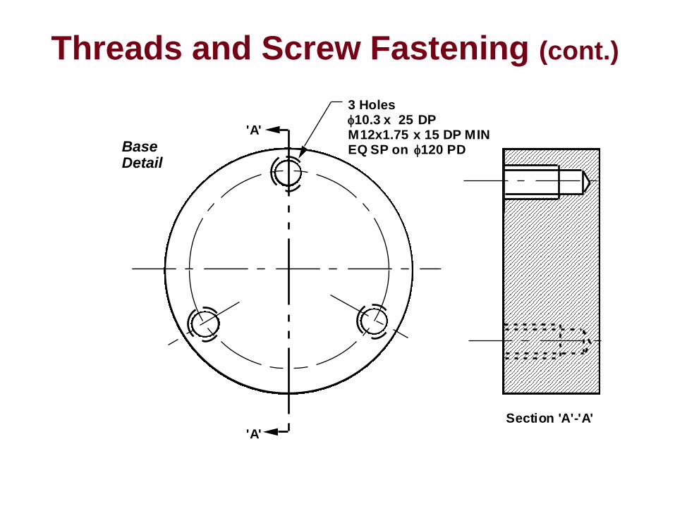
Threads and Screw Fastening (cont.)
'A'
'A'
Section 'A'-'A'
3 Holes 10.3x 25 DP M12x1.75 x 15 DP MIN EQ SP on 120 PD Base
Detail
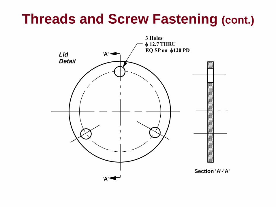
Threads and Screw Fastening (cont.)
LidDetail
'A'
'A'
Section 'A'-'A'
3 Holes
12.7 THRU
EQ SP on 120 PD
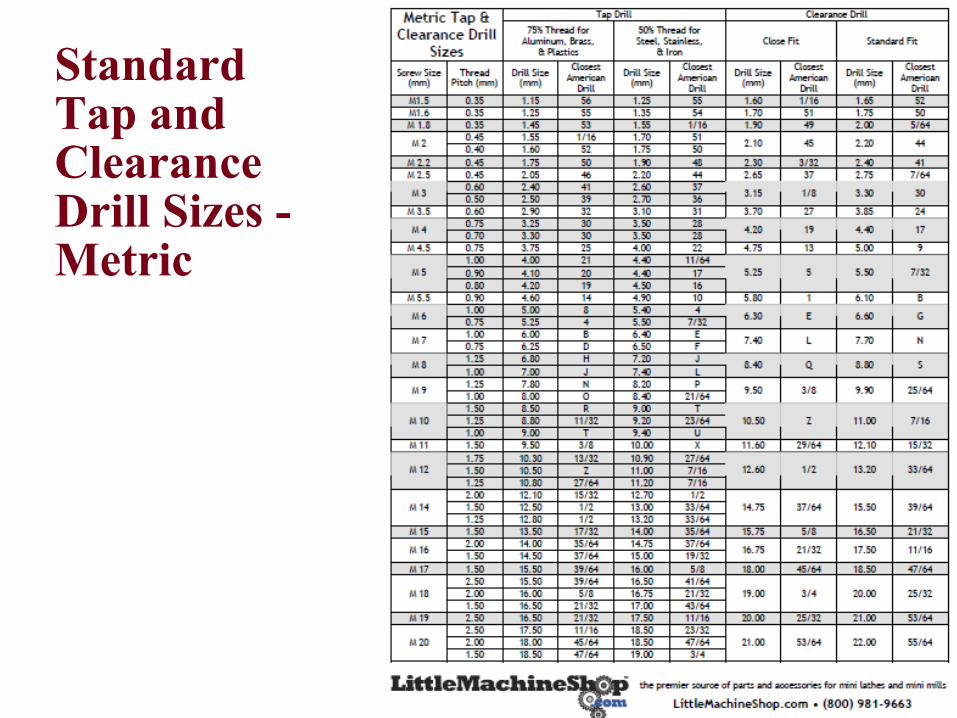
Standard Tap and Clearance Drill Sizes -Metric
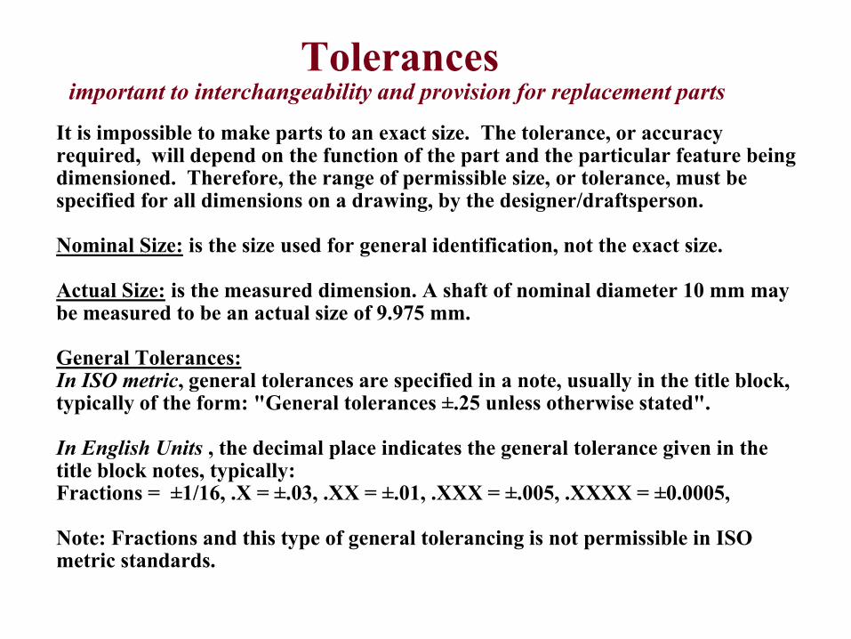
Tolerancesimportant to interchangeability and provision for replacement parts
It is impossible to make parts to an exact size. The tolerance, or accuracy required, will depend on the function of the part and the particular feature being dimensioned. Therefore, the range of permissible size, or tolerance, must be specified for all dimensions on a drawing, by the designer/draftsperson.
Nominal Size: is the size used for general identification, not the exact size.
Actual Size: is the measured dimension. A shaft of nominal diameter 10 mm may be measured to be an actual size of 9.975 mm.
General Tolerances:In ISO metric, general tolerances are specified in a note, usually in the title block, typically of the form: "General tolerances ±.25 unless otherwise stated".
In English Units , the decimal place indicates the general tolerance given in the title block notes, typically:Fractions = ±1/16, .X = ±.03, .XX = ±.01, .XXX = ±.005, .XXXX = ±0.0005,
Note: Fractions and this type of general tolerancing is not permissible in ISO metric standards.
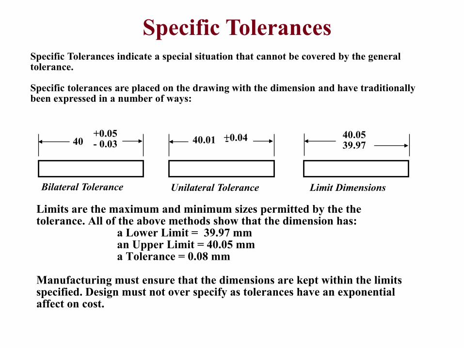
Specific Tolerances indicate a special situation that cannot be covered by the general tolerance.
Specific tolerances are placed on the drawing with the dimension and have traditionally been expressed in a number of ways:
Specific Tolerances
40+0.05- 0.03 40.01 +0.04 40.05
39.97
Bilateral Tolerance Unilateral Tolerance Limit Dimensions
Limits are the maximum and minimum sizes permitted by the the tolerance. All of the above methods show that the dimension has:
a Lower Limit = 39.97 mman Upper Limit = 40.05 mma Tolerance = 0.08 mm
Manufacturing must ensure that the dimensions are kept within the limits specified. Design must not over specify as tolerances have an exponential affect on cost.
-
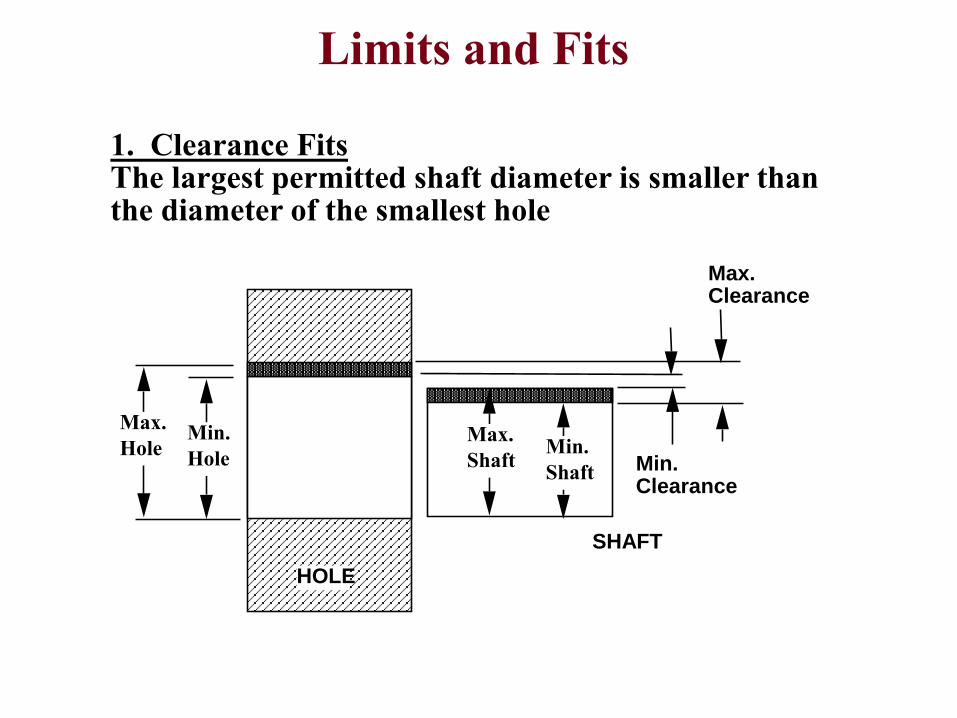
Limits and Fits
1. Clearance FitsThe largest permitted shaft diameter is smaller than the diameter of the smallest hole
Min.
Hole
Max.
Hole
HOLE
SHAFT
Max. Clearance
Min. Clearance
Min.
Shaft
Max.
Shaft
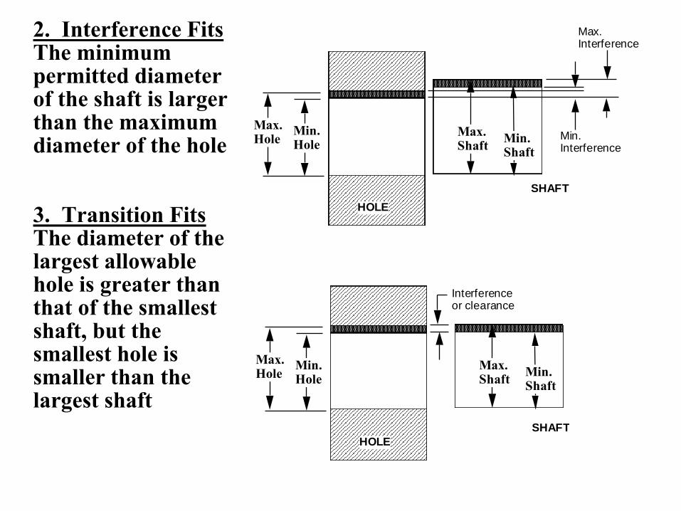
2. Interference FitsThe minimum permitted diameter of the shaft is larger than the maximum diameter of the hole
3. Transition FitsThe diameter of the largest allowable hole is greater than that of the smallest shaft, but the smallest hole is smaller than the largest shaft
Min. Hole
Max. Hole
HOLE
SHAFT
Max. Interference
Min. Interference
Min. Shaft
Max. Shaft
Min. Hole
Max. Hole
HOLE
SHAFT
Interference or clearance
Min. Shaft
Max. Shaft
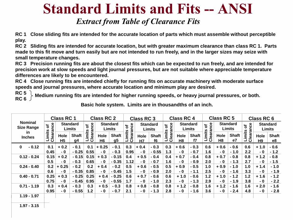
Standard Limits and Fits -- ANSI
RC 1 Close sliding fits are intended for the accurate location of parts which must assemble without perceptible
play.
RC 2 Sliding fits are intended for accurate location, but with greater maximum clearance than class RC 1. Parts
made to this fit move and turn easily but are not intended to run freely, and in the larger sizes may seize with
small temperature changes.
RC 3 Precision running fits are about the closest fits which can be expected to run freely, and are intended for
precision work at slow speeds and light journal pressures, but are not suitable where appreciable temperature
differences are likely to be encountered.
RC 4 Close running fits are intended chiefly for running fits on accurate machinery with moderate surface
speeds and journal pressures, where accurate location and minimum play are desired.
RC 5
RC 6
Basic hole system. Limits are in thousandths of an inch.
Class RC 1
Lim
its o
f
Cle
ara
nce Standard
Limits
Hole
H5
Shaft
g4
Class RC 2
Lim
its o
f
Cle
ara
nce Standard
Limits
Hole
H6
Shaft
g5
Class RC 3
Lim
its o
f
Cle
ara
nce Standard
Limits
Hole
H7
Shaft
f6
Class RC 4
Lim
its o
f
Cle
ara
nce Standard
Limits
Hole
H8
Shaft
f7
Class RC 5
Lim
its o
f
Cle
ara
nce Standard
Limits
Hole
H8
Shaft
e7
Class RC 6
Lim
its o
f
Cle
ara
nce Standard
Limits
Hole
H9
Shaft
e8
Medium running fits are intended for higher running speeds, or heavy journal pressures, or both.
Nominal
Size Range
in
Inches
0 - 0.12 0.1 + 0.2 - 0.1 0.1 + 0.25 - 0.1 0.3 + 0.4 - 0.3 0.3 + 0.6 - 0.3 0.6 + 0.6 - 0.6 0.6 + 1.0 - 0.6
0.45 - 0 - 0.25 0.55 - 0 - 0.3 0.95 - 0 - 0.55 1.3 - 0 - 0.7 1.6 - 0 - 1.0 2.2 - 0 - 1.2
0.12 - 0.24 0.15 + 0.2 - 0.15 0.15 + 0.3 - 0.15 0.4 + 0.5 - 0.4 0.4 + 0.7 - 0.4 0.8 + 0.7 - 0.8 0.8 + 1.2 - 0.8
0.5 - 0 - 0.3 0.65 - 0 - 0.35 1.12 - 0 - 0.7 1.6 - 0 - 0.9 2.0 - 0 - 1.3 2.7 - 0 - 1.5
0.24 - 0.40 0.2 + 0.25 - 0.2 0.2 + 0.4 - 0.2 0.5 + 0.6 - 0.5 0.5 + 0.9 - 0.5 1.0 + 0.9 - 1.0 1.0 + 1.4 - 1.0
0.6 - 0 - 0.35 0.85 - 0 - 0.45 1.5 - 0 - 0.9 2.0 - 0 - 1.1 2.5 - 0 - 1.6 3.3 - 0 - 1.9
0.40 - 0.71 0.25 + 0.3 - 0.25 0.25 + 0.4 - 0.25 0.6 + 0.7 - 0.6 0.6 + 1.0 - 0.6 1.2 + 1.0 - 1.2 1.2 + 1.6 - 1.2
0.75 - 0 - 0.45 0.95 - 0 - 0.55 1.7 - 0 - 1.0 2.3 - 0 - 1.3 2.9 - 0 - 1.9 3.8 - 0 - 2.2
0.71 - 1.19 0.3 + 0.4 - 0.3 0.3 + 0.5 - 0.3 0.8 + 0.8 - 0.8 0.8 + 1.2 - 0.8 1.6 + 1.2 - 1.6 1.6 + 2.0 - 1.6
0.95 - 0 - 0.55 1.2 - 0 - 0.7 2.1 - 0 - 1.3 2.8 - 0 - 1.6 3.6 - 0 - 2.4 4.8 - 0 - 2.8
1.19 - 1.97
1.97 - 3.15
Extract from Table of Clearance Fits
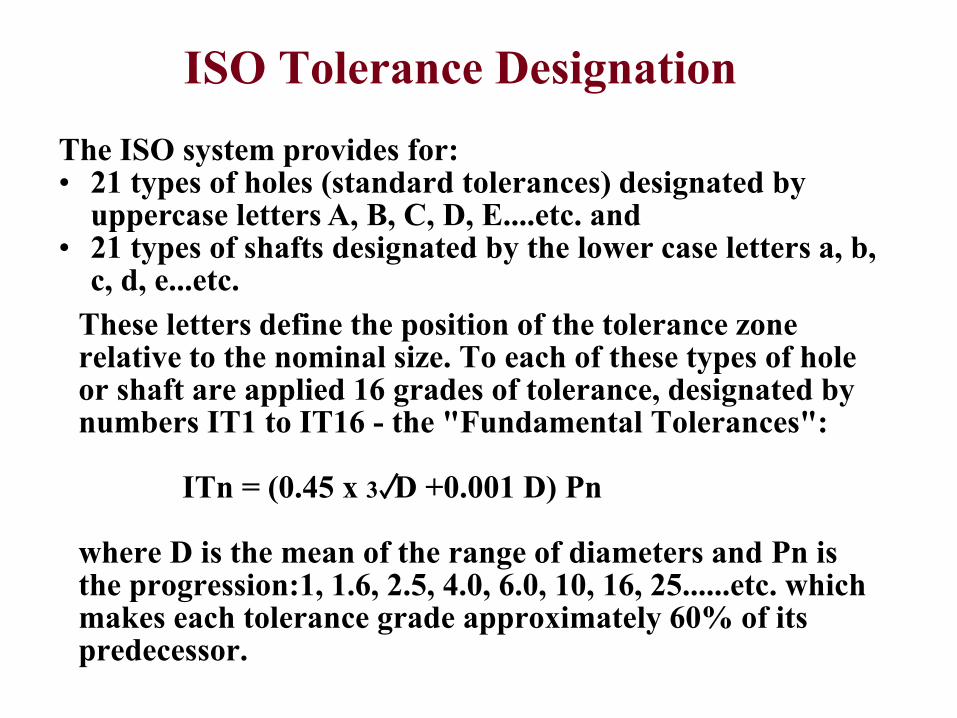
ISO Tolerance Designation
The ISO system provides for:• 21 types of holes (standard tolerances) designated by
uppercase letters A, B, C, D, E....etc. and• 21 types of shafts designated by the lower case letters a, b,
c, d, e...etc.
These letters define the position of the tolerance zone relative to the nominal size. To each of these types of hole or shaft are applied 16 grades of tolerance, designated by numbers IT1 to IT16 - the "Fundamental Tolerances":
ITn = (0.45 x 3 D +0.001 D) Pn
where D is the mean of the range of diameters and Pn is the progression:1, 1.6, 2.5, 4.0, 6.0, 10, 16, 25......etc. which makes each tolerance grade approximately 60% of its predecessor.
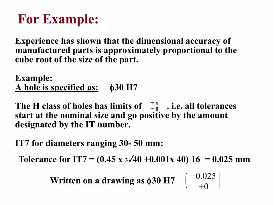
For Example:
Experience has shown that the dimensional accuracy of manufactured parts is approximately proportional to the cube root of the size of the part.
Example:A hole is specified as: 30 H7
The H class of holes has limits of . i.e. all tolerances start at the nominal size and go positive by the amount designated by the IT number.
IT7 for diameters ranging 30- 50 mm:
+ x+ 0
Tolerance for IT7 = (0.45 x 3 40 +0.001x 40) 16 = 0.025 mm
Written on a drawing as 30 H7 +0.025
+0
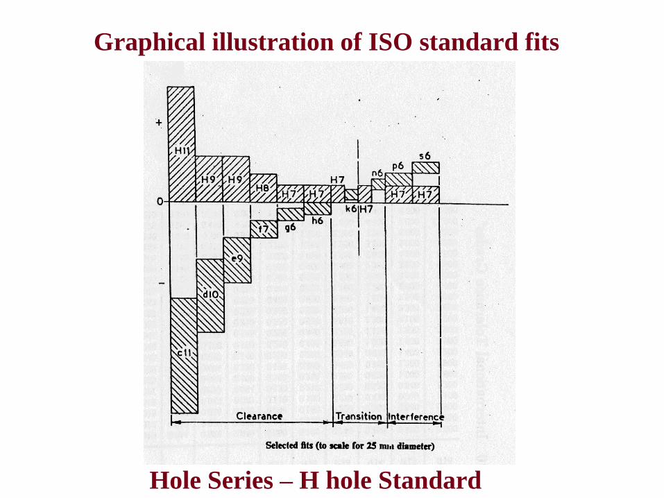
Graphical illustration of ISO standard fits
Hole Series – H hole Standard
Selection of Fits and theISO Hole Basis system
From the above it will be realized that there are a very large number of combinations of hole deviation and tolerance with shaft deviation and tolerance. However, a given manufacturing organization will require a number of different types of fit ranging from tight drive fits to light running fits for bearings etc. Such a series of fits may be obtained using one of two standard systems:
The Shaft Basis System:For a given nominal size a series of fits is arranged for a given nominal size using a standard shaft and varying the limits on the hole.
The Hole Basis System:For a given nominal size, the limits on the hole are kept constant, and a series of fits are obtained by only varying the limits on the shaft.
The HOLE SYSTEM is commonly used because holes are more difficult to produce to a given size and are more difficult to inspect. The H series (lower limit at nominal, 0.00) is typically used and standard tooling (e.g. H7 reamers) and gauges are common for this standard.
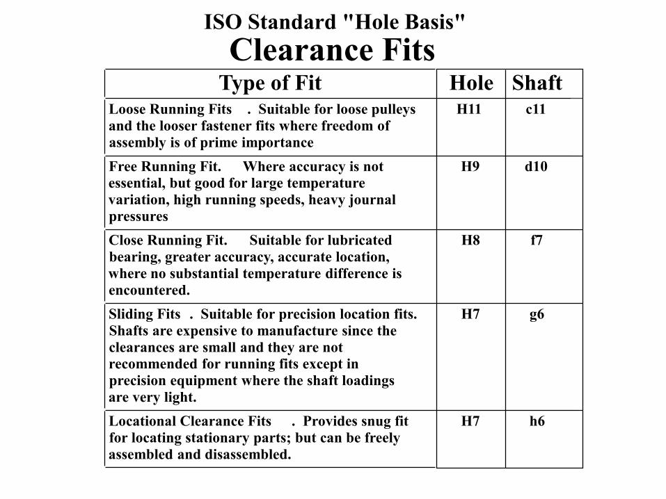
ISO Standard "Hole Basis"
Clearance FitsType of Fit Hole Shaft
Loose Running Fits . Suitable for loose pulleys
and the looser fastener fits where freedom of
assembly is of prime importance
H11 c11
Free Running Fit. Where accuracy is not
essential, but good for large temperature
variation, high running speeds, heavy journal
pressures
H9 d10
Close Running Fit. Suitable for lubricated
bearing, greater accuracy, accurate location,
where no substantial temperature difference is
encountered.
H8 f7
Sliding Fits . Suitable for precision location fits.
Shafts are expensive to manufacture since the
clearances are small and they are not
recommended for running fits except in
precision equipment where the shaft loadings
are very light.
H7 g6
Locational Clearance Fits . Provides snug fit
for locating stationary parts; but can be freely
assembled and disassembled.
H7 h6
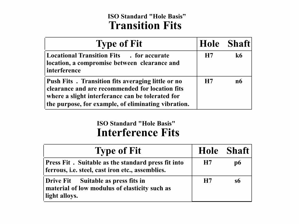
ISO Standard "Hole Basis”
Transition Fits
Type of FitLocational Transition Fits . for accurate
location, a compromise between clearance and
interference
Push Fits . Transition fits averaging little or no
clearance and are recommended for location fits
where a slight interferance can be tolerated for
the purpose, for example, of eliminating vibration.
Hole ShaftH7 k6
H7 n6
ISO Standard "Hole Basis"
Interference Fits
Type of FitPress Fit . Suitable as the standard press fit into
ferrous, i.e. steel, cast iron etc., assemblies.
Drive Fit Suitable as press fits in
material of low modulus of elasticity such as
light alloys.
Hole ShaftH7 p6
H7 s6
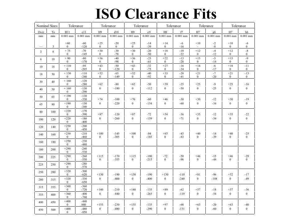
Nominal Sizes Tolerance Tolerance Tolerance Tolerance Tolerance Tolerance
Over To H11 c11 H9 d10 H9 e9 H8 f7 H7 g6 H7 h6
mm
––
mm
3
0.001 mm
+600
0.001 mm
-60-120
0.001 mm
+250
0.001 mm
-200
0.001 mm
+250
0.001 mm
-14-39
0.001 mm
+140
0.001 mm
-6-16
0.001 mm
+10-
0.001 mm
-2-8
0.001 mm
+100
0.001 mm
-60
3 6 + 750
-70-145
+300
-30-78
+300
-20-50
+180
-10-22
+120
-4-12
+120
-80
6 10 + 900
-80-170
+360
-40-98
+360
-25-61
+220
-13-28
+150
-5-14
+150
-90
10 18 + 1100
-95-205
+430
-50-120
+430
-32-75
+270
-16-34
+180
-6-17
+180
-110
18 30 + 1300
-110-240
+520
-65-149
+520
-40-92
+330
-20-41
+210
-7-20
+210
-130
30 40 + 1600
-120-280 +62 -80 +62 -50 +39 -25 +25 -9 +25 -16
40 50 + 1600
-130-290
0 -180 0 -112 0 -50 0 -25 0 0
50 65 + 1900
-130-330 +74 -100 +76 -60 +46 -30 +30 -12 +30 -19
65 80 +1900
-150-340
0 -220 0 -134 0 -60 0 -34 0 0
80 100 +2200
-170-390 +87 -120 +87 -72 +54 -36 +35 -12 +35 -22
100 120 +2200
-180-400
0 -260 0 -159 0 -71 0 -34 0 0
120 140 +2500
-200-450
140 160 +2500
-210-460
+1000
-145-305
+1000
-84-185
+630
-43-83
+400
-14-39
+400
-250
160 180 +2500
-230-480
180 200 +2900
-240-530
200 225 +2900
-260-550
+1150
-170-355
+1150
-100-215
-720
-50-96
+460
-15-44
+460
-290
225 250 +2900
-280-570
250 280 +3200
-300-620 +130 -190 +130 -190 +130 -110 +81 -96 +52 -17
280 315 +3200
-330-650
0 -400 0 -400 0 -240 0 -108 0 -49
315 355 +3600
-360-720 +140 -210 +140 -135 +89 -62 +57 -18 +57 -36
355 400 +3600
-400-760
0 -440 0 -265 0 -119 0 -54 0 0
400 450 +4000
-440840 +155 -230 +155 -135 +97 -68 +63 -20 +63 -40
450 500 +4000
-480-850
0 -480 0 -290 0 -131 0 -60 0 0
ISO Clearance Fits
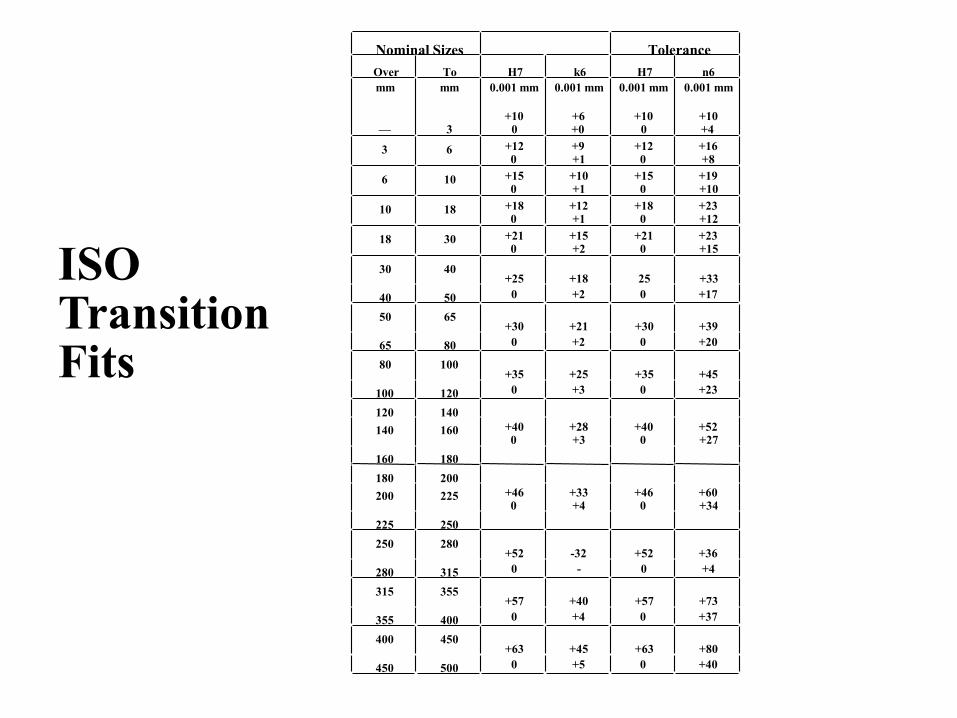
Nominal Sizes Tolerance
Over To H7 k6 H7 n6
mm
––
mm
3
0.001 mm
+100
0.001 mm
+6+0
0.001 mm
+100
0.001 mm
+10+4
3 6 +120
+9+1
+120
+16+8
6 10 +150
+10+1
+150
+19+10
10 18 +180
+12+1
+180
+23+12
18 30 +210
+15+2
+210
+23+15
30 40+25 +18 25 +33
40 50 0 +2 0 +17
50 65+30 +21 +30 +39
65 80 0 +2 0 +20
80 100+35 +25 +35 +45
100 120 0 +3 0 +23
120 140
140 160 +400
+28+3
+400
+52+27
160 180
180 200
200 225 +460
+33+4
+460
+60+34
225 250
250 280+52 -32 +52 +36
280 315 0 - 0 +4
315 355+57 +40 +57 +73
355 400 0 +4 0 +37
400 450+63 +45 +63 +80
450 500 0 +5 0 +40
ISO TransitionFits
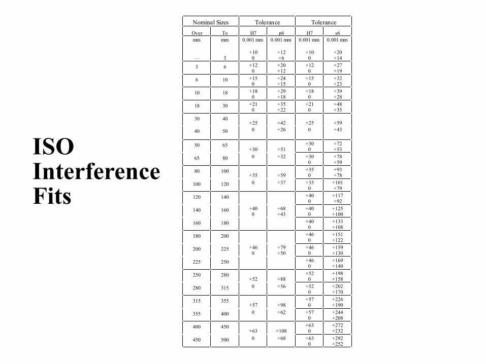
Nominal Sizes Tolerance Tolerance
Over To H7 p6 H7 s6
mm
––
mm
3
0.001 mm
+100
0.001 mm
+12+6
0.001 mm
+100
0.001 mm
+20+14
3 6 +120
+20+12
+120
+27+19
6 10 +150
+24+15
+150
+32+23
10 18 +180
+29+18
+180
+39+28
18 30 +210
+35+22
+210
+48+35
30 40+25 +42 +25 +59
40 50 0 +26 0 +43
50 65+30 +51
+300
+72+53
65 80 0 +32 +300
+78+59
80 100+35 +59
+350
+93+78
100 120 0 +37 +350
+101+79
120 140 +400
+117+92
140 160 +400
+68+43
+400
+125+100
160 180 +400
+133+108
180 200 +460
+151+122
200 225 +460
+79+50
+460
+159+130
225 250 +460
+169+140
250 280+52 +88
+520
+198+158
280 315 0 +56 +520
+202+170
315 355+57 +98
+570
+226+190
355 400 0 +62 +570
+244+208
400 450+63 +108
+630
+272+232
450 500 0 +68 +630
+292+252
ISO InterferenceFits
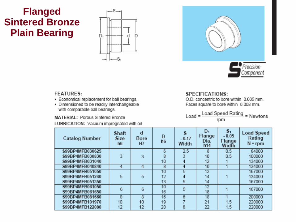
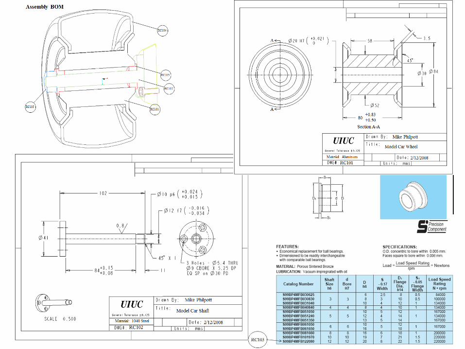
Flanged Sintered Bronze
Plain Bearing
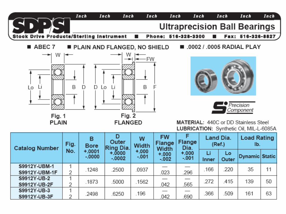
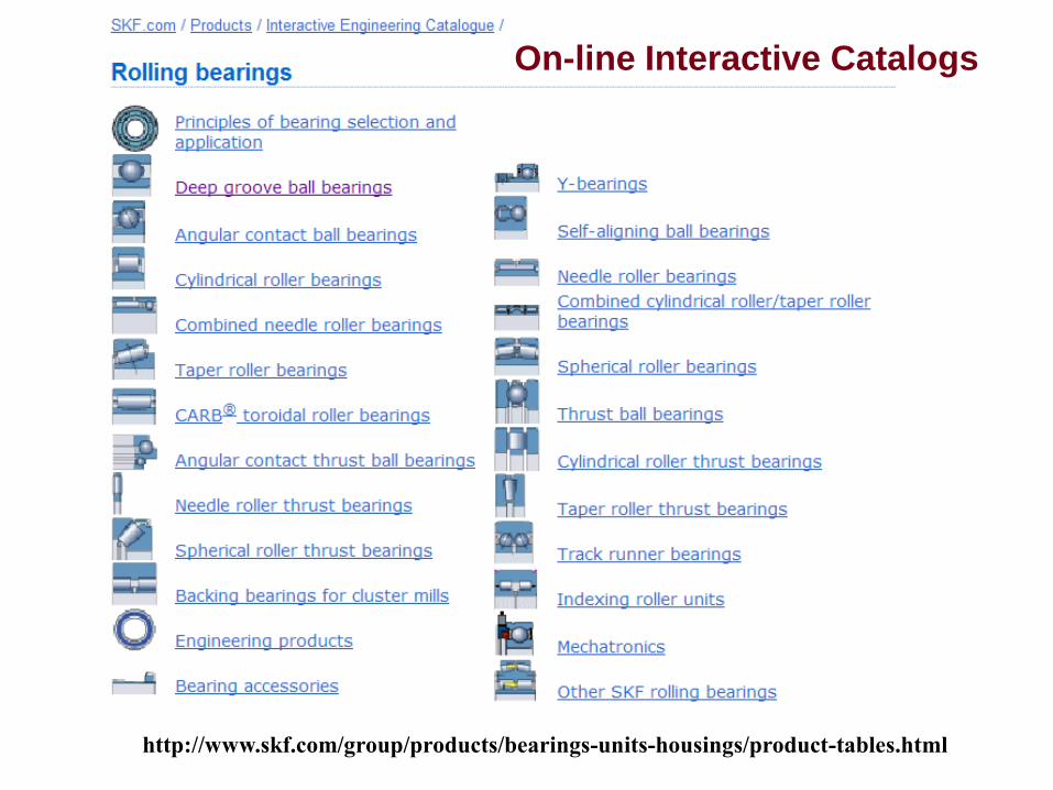
On-line Interactive Catalogs
http://www.skf.com/group/products/bearings-units-housings/product-tables.html
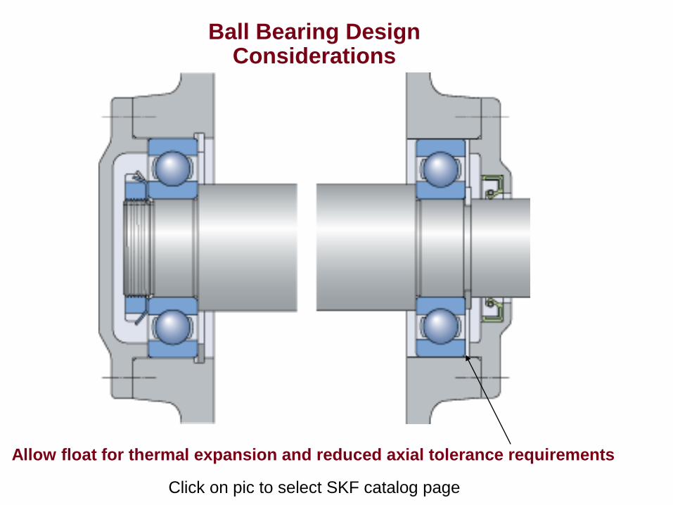
Ball Bearing Design Considerations
Click on pic to select SKF catalog page
Allow float for thermal expansion and reduced axial tolerance requirements
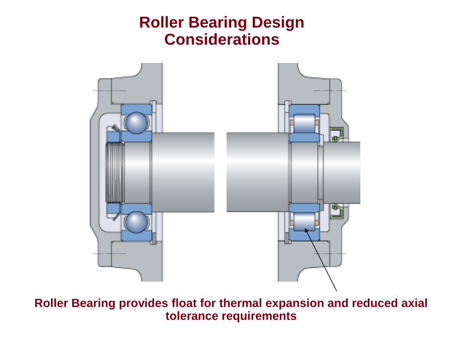
Roller Bearing Design Considerations
Roller Bearing provides float for thermal expansion and reduced axial tolerance requirements
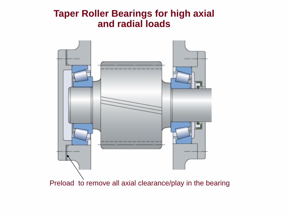
Taper Roller Bearings for high axial and radial loads
Preload to remove all axial clearance/play in the bearing
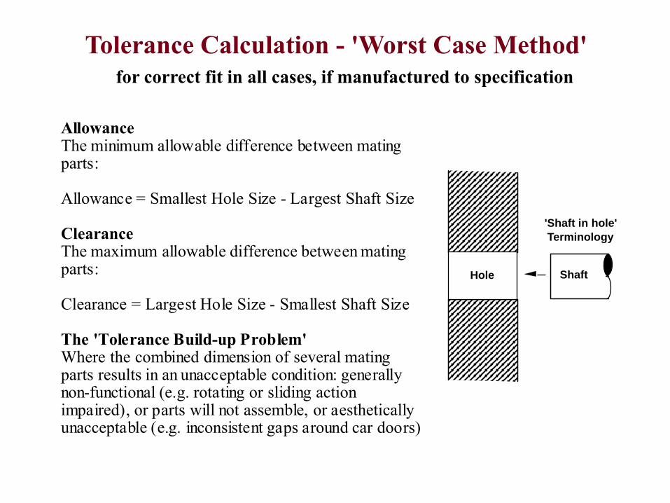
Tolerance Calculation - 'Worst Case Method'
for correct fit in all cases, if manufactured to specification
'Shaft in hole'
ShaftHole
Terminology
Allowance The minimum allowable difference between mating parts: Allowance = Smallest Hole Size - Largest Shaft Size Clearance The maximum allowable difference between mating parts: Clearance = Largest Hole Size - Smallest Shaft Size The 'Tolerance Build-up Problem' Where the combined dimension of several mating parts results in an unacceptable condition: generally non-functional (e.g. rotating or sliding action impaired), or parts will not assemble, or aesthetically unacceptable (e.g. inconsistent gaps around car doors)
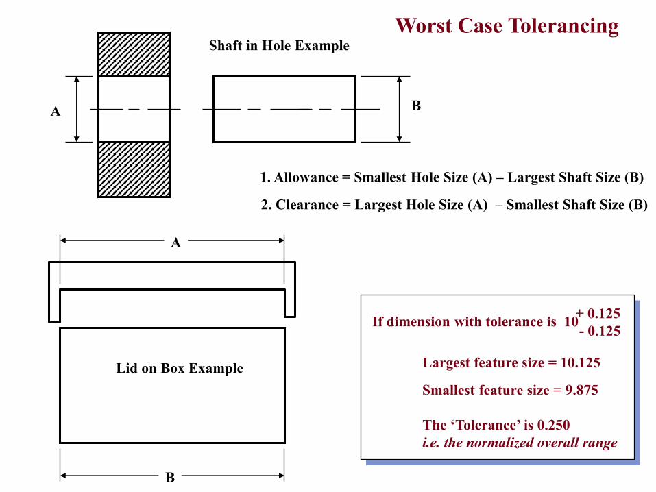
Shaft in Hole Example
Lid on Box Example
1. Allowance = Smallest Hole Size (A) – Largest Shaft Size (B)
2. Clearance = Largest Hole Size (A) – Smallest Shaft Size (B)
A
A
B
B
If dimension with tolerance is 10 + 0.125
- 0.125
Largest feature size = 10.125
Smallest feature size = 9.875
The ‘Tolerance’ is 0.250
i.e. the normalized overall range
Worst Case Tolerancing
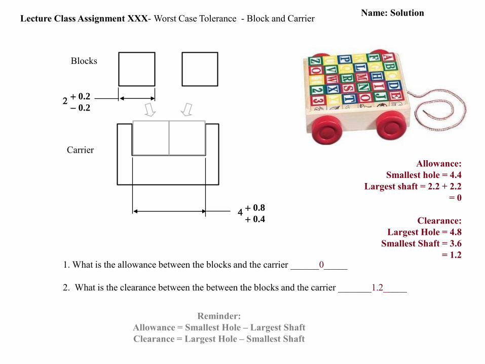
Lecture Class Assignment XXX- Worst Case Tolerance - Block and Carrier
Blocks
Carrier
1. What is the allowance between the blocks and the carrier ______0_____
2. What is the clearance between the between the blocks and the carrier _______1.2_____
2+0.2
- 0.2
4+0.8
+0.4
Allowance:
Smallest hole = 4.4
Largest shaft = 2.2 + 2.2
= 0
Clearance:
Largest Hole = 4.8
Smallest Shaft = 3.6
= 1.2
Name: Solution
Reminder:
Allowance = Smallest Hole – Largest Shaft
Clearance = Largest Hole – Smallest Shaft
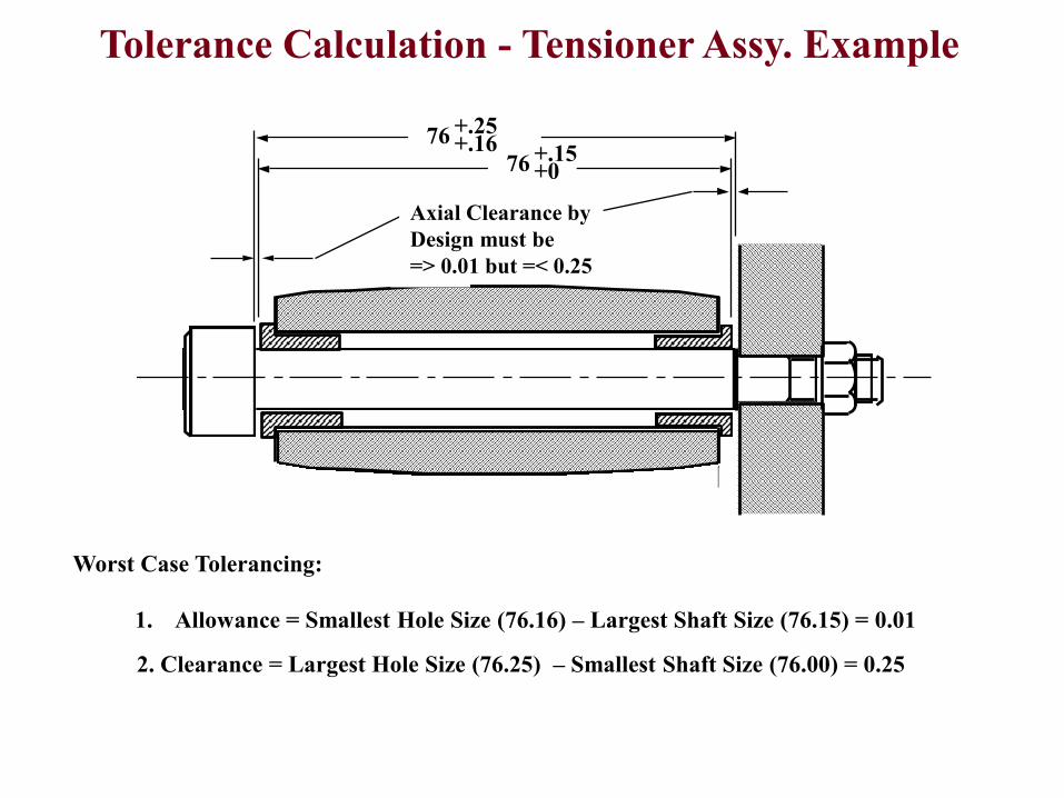
Tolerance Calculation - Tensioner Assy. Example
Axial Clearanceby design must be
Š.25 but >0.01
A
B
X
<0.25
76 +.25+.16
76 +.15+0
1. Allowance = Smallest Hole Size (76.16) – Largest Shaft Size (76.15) = 0.01
2. Clearance = Largest Hole Size (76.25) – Smallest Shaft Size (76.00) = 0.25
Worst Case Tolerancing:
Axial Clearance by
Design must be
=> 0.01 but =< 0.25
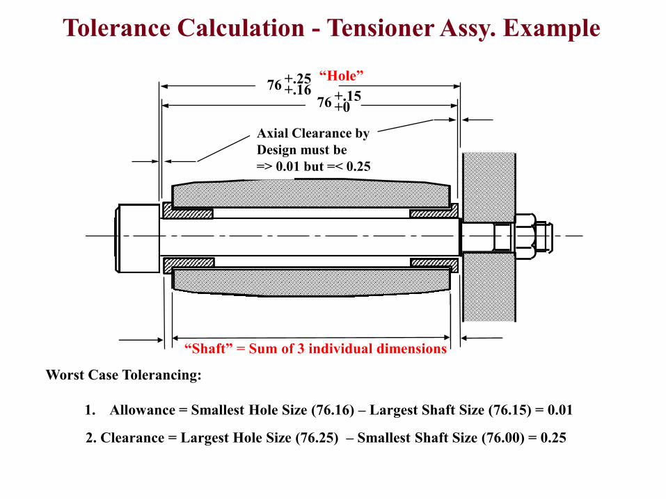
“Hole”
“Shaft” = Sum of 3 individual dimensions
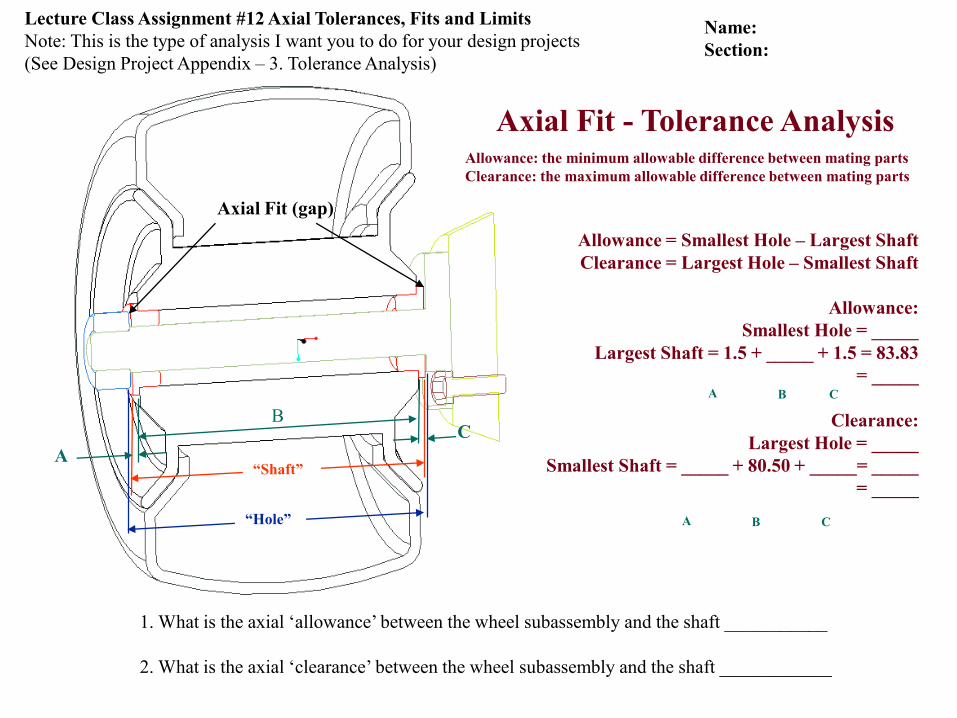
Axial Fit (gap)
1. What is the axial ‘allowance’ between the wheel subassembly and the shaft ___________
2. What is the axial ‘clearance’ between the wheel subassembly and the shaft ____________
Allowance = Smallest Hole – Largest Shaft
Clearance = Largest Hole – Smallest Shaft
Allowance:
Smallest Hole = _____
Largest Shaft = 1.5 + _____ + 1.5 = 83.83
= _____
Clearance:
Largest Hole = _____
Smallest Shaft = _____ + 80.50 + _____= _____
= _____
Allowance: the minimum allowable difference between mating parts
Clearance: the maximum allowable difference between mating parts
Axial Fit - Tolerance Analysis
“Hole”
“Shaft”A
BC
CBA
CBA
Lecture Class Assignment #12 Axial Tolerances, Fits and Limits
Note: This is the type of analysis I want you to do for your design projects
(See Design Project Appendix – 3. Tolerance Analysis)
Name:
Section:
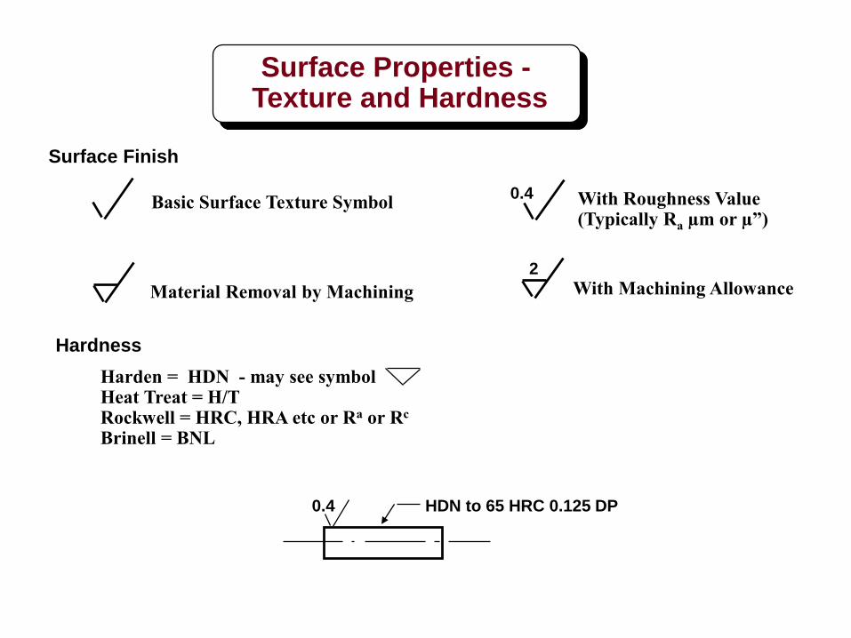
Basic Surface Texture Symbol With Roughness Value(Typically Ra µm or µ”)
0.4
Material Removal by Machining With Machining Allowance2
Harden = HDN - may see symbolHeat Treat = H/TRockwell = HRC, HRA etc or Ra or Rc
Brinell = BNL
Hardness
Surface Finish
HDN to 65 HRC 0.125 DP0.4
Surface Properties -Texture and Hardness
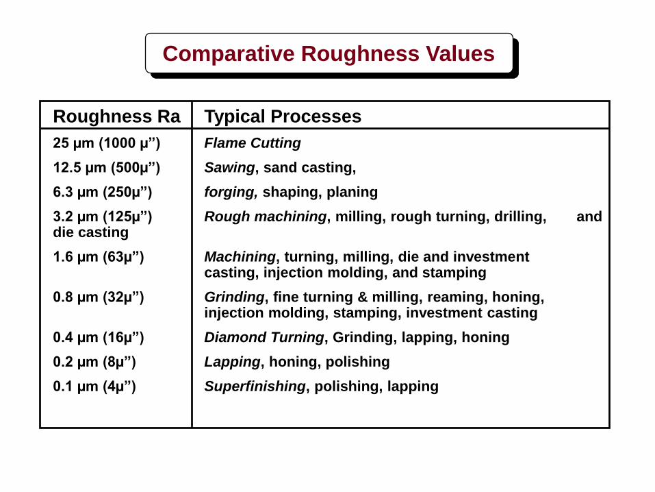
Comparative Roughness Values
Roughness Ra Typical Processes
25 µm (1000 µ”) Flame Cutting
12.5 µm (500µ”) Sawing, sand casting,
6.3 µm (250µ”) forging, shaping, planing
3.2 µm (125µ”) Rough machining, milling, rough turning, drilling, and die casting
1.6 µm (63µ”) Machining, turning, milling, die and investment casting, injection molding, and stamping
0.8 µm (32µ”) Grinding, fine turning & milling, reaming, honing, injection molding, stamping, investment casting
0.4 µm (16µ”) Diamond Turning, Grinding, lapping, honing
0.2 µm (8µ”) Lapping, honing, polishing
0.1 µm (4µ”) Superfinishing, polishing, lapping
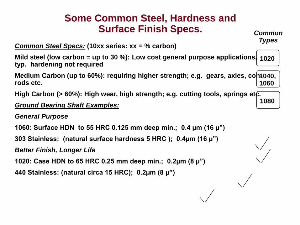
Some Common Steel, Hardness and Surface Finish Specs.
Common Steel Specs: (10xx series: xx = % carbon)
Mild steel (low carbon = up to 30 %): Low cost general purpose applications, typ. hardening not required
Medium Carbon (up to 60%): requiring higher strength; e.g. gears, axles, con-rods etc.
High Carbon (> 60%): High wear, high strength; e.g. cutting tools, springs etc.
Ground Bearing Shaft Examples:
General Purpose
1060: Surface HDN to 55 HRC 0.125 mm deep min.; 0.4 µm (16 µ”)
303 Stainless: (natural surface hardness 5 HRC ); 0.4µm (16 µ”)
Better Finish, Longer Life
1020: Case HDN to 65 HRC 0.25 mm deep min.; 0.2µm (8 µ”)
440 Stainless: (natural circa 15 HRC); 0.2µm (8 µ”)
1020
1040,1060
1080
CommonTypes
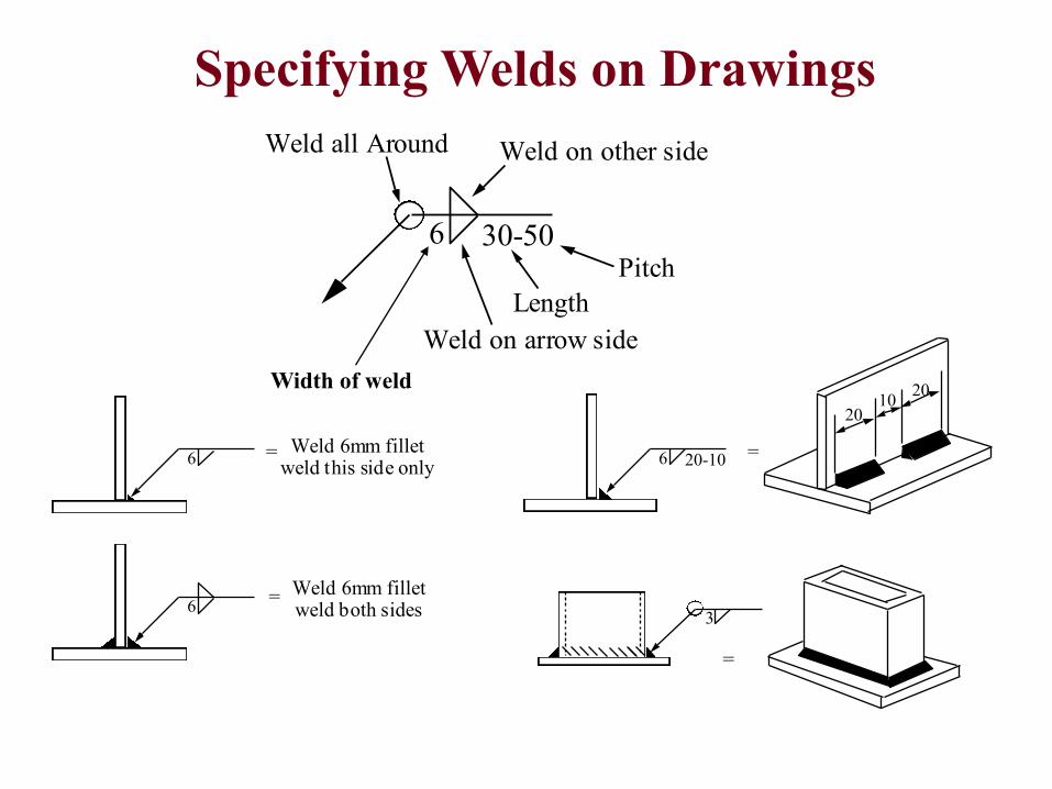
6 20-10
1020
20
=
3
=
Weld on arrow side
Weld on other sideWeld all Around
Length
Pitch
6 30-50
6Weld 6mm fillet
weld this side only
6Weld 6mm fillet weld both sides
=
=
Specifying Welds on Drawings
Width of weld


![DRAWING AND 3D MODEL MANAGEMENT AND …lhc-proj-qawg.web.cern.ch/lhc-proj-qawg/CD-ROM/Quality/QA305.pdf · Buildings and Civil Engineering Works" [ 9]. Drawing sequential numbers](https://static.fdocuments.in/doc/165x107/5aa4a01e7f8b9a1d728c1f4b/drawing-and-3d-model-management-and-lhc-proj-qawgwebcernchlhc-proj-qawgcd-romqualityqa305pdfbuildings.jpg)