Engineer To Engineer Note EE-199 - Analog Devices To Engineer Note EE-199 a Technical Notes on using...
29
Engineer To Engineer Note EE-199 a Technical Notes on using Analog Devices' DSP components and development tools Contact our technical support by phone: (800) ANALOG-D or e-mail: [email protected] Or visit our on-line resources http://www.analog.com/dsp and http://www.analog.com/dsp/EZAnswers Link Port Booting the ADSP-21161 SHARC® DSP Contributed by Andrew Caldwell August 19, 2003 Copyright 2003, Analog Devices, Inc. All rights reserved. Analog Devices assumes no responsibility for customer product design or the use or application of customers’ products or for any infringements of patents or rights of others which may result from Analog Devices assistance. All trademarks and logos are property of their respective holders. Information furnished by Analog Devices Applications and Development Tools Engineers is believed to be accurate and reliable, however no responsibility is assumed by Analog Devices regarding technical accuracy and topicality of the content provided in Analog Devices’ Engineer-to-Engineer Notes. Introduction The following engineer note will discuss the steps required in order to successfully link boot one slave ADSP-21161 SHARC® DSP from another master ADSP-21161 DSP. We will discuss the link boot process from both the perspective of the master device and the slave. There are four possible boot modes: EPROM, Host, SPI, and Link Booting. This application note will go into detail about the complications that must be considered when performing a link port boot, the link port kernel and how to use the loader utility to create a bootable file. Example code is included in the note itself as well as being provided in the accompanying zip file (EE199.zip). The example consists of code for the master ADSP-21161 SHARC DSP that will transfer the boot code to a slave ADSP-21161 SHARC DSP through the link ports, the link port boot kernel executed on the slave device being booted and a simple blink program that is executed after the boot kernel. This engineer note briefly describes the various booting methods for the ADSP-21161 and how to configure a slave device for link port booting. The reader is introduced to the loader utility and link kernels and how these are used by the VisualDSP++™ IDDE to create a file suitable for booting an ADSP-21161 SHARC DSP through the link port. This is followed by a description of the actual booting process and how the slave device uses the boot kernel to bring the core into a state in which it is ready to receive the actual program to be booted. Some hardware issues associated with link port booting and how to accommodate for these issues in software are then described. Finally the reader is taken through a step-by-step example of link port booting one ADSP-21161 DSP from another and is introduced to the techniques used to debug a link port boot problem. This section includes fully documented code. VisualDSP++™ Tools Required This engineer note and the accompanying projects included in EE199.zip were developed and tested for VisualDSP++ 3.0 for the SHARC family with Service Pack 1 installed. The loader utility used to create the loader files was: ADSP-21100 Family Loader version 2.0.3.18 If you have an earlier version of the loader utility then please make sure you have the correct version of VisualDSP++ installed as detailed above and you have downloaded and installed the following file from our ftp site at ftp://ftp.analog.com/pub/tools/patches sharcloader_4.1.3.11_and_hhloader_2.0.3.18_a nd_sharcloaderpropertypage_1.2.4.1_and_21161 loaderpropertypage_1.0.1.6.zip Also make sure you read the accompanying release note: sharcloader_4.1.3.11_and_hhloader_2.0.3.18_a nd_sharcloaderpropertypage_1.2.4.1_and_21161 loaderpropertypage_1.0.1.6_ReleaseNote.doc
Transcript of Engineer To Engineer Note EE-199 - Analog Devices To Engineer Note EE-199 a Technical Notes on using...

Engineer To Engineer Note EE-199
a
Technical Notes on using Analog Devices' DSP components and development toolsContact our technical support by phone: (800) ANALOG-D or e-mail: [email protected] visit our on-line resources http://www.analog.com/dsp and http://www.analog.com/dsp/EZAnswers
Link Port Booting the ADSP-21161 SHARC® DSP Contributed by Andrew Caldwell August 19, 2003
Copyright 2003, Analog Devices, Inc. All rights reserved. Analog Devices assumes no responsibility for customer product design or the use or application of customers’ products or for any infringements of patents or rights of others which may result from Analog Devices assistance. All trademarks and logos are property of their respective holders. Information furnished by Analog Devices Applications and Development Tools Engineers is believed to be accurate and reliable, however no responsibility is assumed by Analog Devices regarding technical accuracy and topicality of the content provided in Analog Devices’ Engineer-to-Engineer Notes.
Introduction The following engineer note will discuss the steps required in order to successfully link boot one slave ADSP-21161 SHARC® DSP from another master ADSP-21161 DSP. We will discuss the link boot process from both the perspective of the master device and the slave.
There are four possible boot modes: EPROM, Host, SPI, and Link Booting. This application note will go into detail about the complications that must be considered when performing a link port boot, the link port kernel and how to use the loader utility to create a bootable file. Example code is included in the note itself as well as being provided in the accompanying zip file (EE199.zip). The example consists of code for the master ADSP-21161 SHARC DSP that will transfer the boot code to a slave ADSP-21161 SHARC DSP through the link ports, the link port boot kernel executed on the slave device being booted and a simple blink program that is executed after the boot kernel.
This engineer note briefly describes the various booting methods for the ADSP-21161 and how to configure a slave device for link port booting. The reader is introduced to the loader utility and link kernels and how these are used by the VisualDSP++™ IDDE to create a file suitable for booting an ADSP-21161 SHARC DSP through the link port. This is followed by a description of the actual booting process and how the slave device uses the boot kernel to bring the core into a state in which it is ready to
receive the actual program to be booted. Some hardware issues associated with link port booting and how to accommodate for these issues in software are then described. Finally the reader is taken through a step-by-step example of link port booting one ADSP-21161 DSP from another and is introduced to the techniques used to debug a link port boot problem. This section includes fully documented code.
VisualDSP++™ Tools Required This engineer note and the accompanying projects included in EE199.zip were developed and tested for VisualDSP++ 3.0 for the SHARC family with Service Pack 1 installed. The loader utility used to create the loader files was: ADSP-21100 Family Loader version 2.0.3.18
If you have an earlier version of the loader utility then please make sure you have the correct version of VisualDSP++ installed as detailed above and you have downloaded and installed the following file from our ftp site at ftp://ftp.analog.com/pub/tools/patches sharcloader_4.1.3.11_and_hhloader_2.0.3.18_and_sharcloaderpropertypage_1.2.4.1_and_21161loaderpropertypage_1.0.1.6.zip
Also make sure you read the accompanying release note: sharcloader_4.1.3.11_and_hhloader_2.0.3.18_and_sharcloaderpropertypage_1.2.4.1_and_21161loaderpropertypage_1.0.1.6_ReleaseNote.doc

a
Link Port Booting the ADSP-21161 SHARC® DSP (EE-199) Page 2 of 30
Contents Introduction.................................................................................................................................................... 1
VisualDSP++™ Tools Required .................................................................................................................. 1
Contents ......................................................................................................................................................... 2
List of Figures ................................................................................................................................................ 3
ADSP-21161 Booting Methods ..................................................................................................................... 4
Loader Kernel and Loader Utility.................................................................................................................. 4
Loader file format .......................................................................................................................................... 5
Understanding the contents of the loader file ................................................................................................ 6
Link port boot kernel structure ...................................................................................................................... 9
Link Port Booting Process ........................................................................................................................... 10
Hardware Considerations............................................................................................................................. 12
Debugging Guidelines ................................................................................................................................. 12
Setting up the VisualDSP++ Configurator .............................................................................................. 12
Creating a boot kernel for debug purposes .............................................................................................. 15
Debugging the boot process..................................................................................................................... 16
Step 1: Open up VisualDSP++ IDDE.................................................................................................. 16
Step 2: Setting up the VisualDSP++ Environment.............................................................................. 16
Step 3: Setup Breakpoints.................................................................................................................... 18
Step 4: Starting the debug process....................................................................................................... 18
Step 5: Analyzing the registers ............................................................................................................ 18
References.................................................................................................................................................... 30
Document History........................................................................................................................................ 30
Appendix 1: Blink_Example Source code................................................................................................... 26
Appendix 2: Master Source Code................................................................................................................ 28

a
Link Port Booting the ADSP-21161 SHARC® DSP (EE-199) Page 3 of 30
List of Figures Figure 1 Elfloader Operation ......................................................................................................................... 5
Figure 2 Loader Utility Options..................................................................................................................... 5
Figure 3 Loader File Formats ........................................................................................................................ 6
Figure 4 16-bit Include file format ................................................................................................................ 7
Figure 5 Tag and control words..................................................................................................................... 7
Figure 6 Link Port kernel functions and locations......................................................................................... 9
Figure 7 DMA Channel 8 reset values......................................................................................................... 10
Figure 8: DMA Channel 8 setup in final_init .............................................................................................. 11
Figure 9: VisualDSP++ Configurator .......................................................................................................... 13
Figure 10: Platform Properties..................................................................................................................... 14
Figure 11: Device Properties ....................................................................................................................... 14
Figure 12: Loader Utility ............................................................................................................................. 15
Figure 13: New session and session list....................................................................................................... 16
Figure 14: VisualDSP++ IDDE Setup immediately after opening the kernel debug session ..................... 17
Figure 15: VisualDSP++ IDDE after environment setup and symbol load................................................. 17
Figure 16: Breakpoint location within kernel .............................................................................................. 18
Figure 17: Register contents showing tag number....................................................................................... 18
Figure 18: Register contents showing address and word count................................................................... 19
Figure 19: Register contents showing first instruction ................................................................................ 19
Figure 20: 16-bit data initialization ............................................................................................................. 20
Figure 21: 16-bit data zero initialization ..................................................................................................... 20
Figure 22: 32-bit data initialization ............................................................................................................. 20
Figure 23: 32-bit data zero initialization ..................................................................................................... 21
Figure 24: 40-bit data initialization ............................................................................................................. 21
Figure 25: 40-bit data zero initialization ..................................................................................................... 21
Figure 26: 64-bit data initialization ............................................................................................................. 22
Figure 27: 64-bit data zero initialization ..................................................................................................... 22
Figure 28: Final Init ..................................................................................................................................... 22
Figure 29: Alteration to Reset interrupt Vector for debugging purposes .................................................... 23
Figure 30: Assemble options for additional debug...................................................................................... 24

a
Link Port Booting the ADSP-21161 SHARC® DSP (EE-199) Page 4 of 30
ADSP-21161 Booting Methods There are four booting methods possible on the ADSP-21161 SHARC DSP. These are EPROM, host, SPI, and link port booting. Booting is the method of taking data and application code into the processor so it may then begin instruction execution. EPROM booting is achieved by reading data from the EPROM through the external port. Host booting is also achieved through the external port although DMA (Direct Memory Access) configuration is slightly different to that when EPROM boot method is selected. For more information on these two booting methods please refer to pages 6-74 through 6-80 of [1]. SPI booting is achieved when the ADSP-21161 is configured for SPI boot mode, in this mode the DSP receives 8-bit, 16-bit or 32-bit wide data through the SPI receive buffer. Refer to pages 11-36 through 11-46 of [1] for further details. Finally we have link port booting. This is achieved by reading 4-bit wide data through link buffer 0. This data may come from another DSPs link port such as a member of the SHARC family, an ADSP-21160 or another ADSP-21161. The data could also come from an external device such as an FPGA, as long as data is provided in 4 bit widths and the external device provides a clock signal to the link port assigned to link buffer 0. There is also a no boot mode; in this mode the DSP begins executing instructions from external memory.
The various booting modes are configured in hardware. The ADSP-21161 samples three pins during reset, these three pins are: EBOOT, LBOOT, and /BMS. For the ADSP-21161 EZ-KIT Lite these pins may be configured through JP20 which is labeled “Boot Mode”. Table 1 shows the various boot modes and the configuration required for each of the EBOOT, LBOOT and /BMS pins for the DSP to boot via that method.
EBOOT LBOOT /BMS Booting Mode
1 0 1 (Output) EPROM
0 0 1 (Input) Host Processor
0 1 0 (Input) Serial Boot (SPI)
0 1 1 (Input) Link Port
0 0 0 (Input) No Boot
1 1 X (Input) Reserved
Table 1 Boot Mode pin configuration
On initial power up or after a hardware/software reset, the ADSP-21161 is automatically configured for a 256 Word DMA through the external port, SPI port or link port. For the ‘No Boot’ configuration the DSP core starts executing code directly from external memory and no DMA is required. This 256 word DMA is used to load the boot kernel into the DSP memory. This kernel serves as a loading routine for the application.
Loader Kernel and Loader Utility The loader utility (elfloader.exe) generates boot-loadable files for the ADSP-21161 by processing the executable files. The output of the loader utility is a boot-loadable file with a “.LDR” extension.
The loader utility allows the user to choose various options such as the boot type (Prom, Host, Link, SPI), boot kernel file, and the type of file format (hex, ASCII, binary or include). All this information is located under the “Load” tab of the project options window in the VisualDSP++ 3.0 environment as shown in Figure 2.

a
Link Port Booting the ADSP-21161 SHARC® DSP (EE-199) Page 5 of 30
Loader Kernel(.dxe) DSP 6
Executable(.dxe)
DSP 5Executable
(.dxe)DSP 4
Executable(.dxe)
DSP 3Executable
(.dxe)DSP 2
Executable(.dxe)
DSP 1Executable
(.dxe)
DSP 0Executable
(.dxe)
Loader file(.ldr)
Elfloader.exeLoader options
Figure 1 Elfloader Operation
There are four types of loader kernel to choose from depending on whether host boot, SPI boot, EPROM boot and link boot is being used. After selecting the boot type, you can select the file format of the generated loader file and also select the associated kernel for the boot method. Default kernels are provided with the VisualDSP++ software. In VisualDSP ++ 3.0, four kernels are supplied, one for each boot type: host, SPI, EPROM, and link boot. A single executable (161_prom.dxe, 161_host.dxe, 161_spi.dxe, 161_link.dxe) can now initialize code in all four external memory widths.
Figure 2 Loader Utility Options
Please note that in previous versions of the VisualDSP++ software, four separate executable kernel files were provided for each boot type. The one that was required was dependant upon the external memory data bus widths in which the DSP was to read and/or write to. i.e. 161_link8.dxe, 161_link16.dxe, 161_link32.dxe, 161_link48.dxe.
Each boot kernel is less than or equal to 256 words in length and is pre-pended to the user code when the loader utility is run. The ADSP-21161, like all the other ADSP-21xxx devices, has a special hardware feature that allows for a maximum of 256 instruction words to be loaded in upon reset. This code must then be responsible for placing the application code and data into the correct memory locations such as external SDRAM, internal program memory and various data memory locations before overwriting itself with application code allowing for maximum memory usage for the application. The detailed functionality of the link port boot kernel and it’s operation is not covered in this document as the kernel source files are very well documented and it is advised that a user study these to gain a better understanding of the operation of the kernel.
Loader file format Before we take a closer look at the link port loader boot kernel and how it operates we need to be able to understand the file format of the boot loader file that is created by the loader utility and its contents.
Both the Include and ASCII file formats generate 16-bit hexadecimal values. The only difference between the two being that the Include format consists of comma separated 16-bit values consisting of three values per line whereas the ASCII file format has one 16-bit value per line and is not comma separated as shown in Figure 3.

a
Link Port Booting the ADSP-21161 SHARC® DSP (EE-199) Page 6 of 30
Take the following three instructions:
0x063e04040009 0x0f7b00000000 0x06be00040054 16-bit Include format representation:
0x0009, 0x0404, 0x063e 0x0000, 0x0000, 0x0f7b 0x0054, 0x0004, 0x06be 16-bit ASCII format representation:
0x0009 0x0404 0x063e 0x0000 0x0000 0x0f7b 0x0054 0x0004 0x06be
Figure 3 Loader File Formats
The Include file format confirms to the C-style include format and can be included into a C program as shown in Code listing 1 or used to include into any assembly program as shown in Code listing 2.
int dm Boot_Data[N] = { #include “boot_file.ldr” };
Code listing 1 C-style inclusion of a loader file
.var Boot_Data[N] = “boot_file.ldr”;
Code listing 2 Assembly style inclusion of a loader file
The ASCII file format allows for simple inclusion into an assembly file in the same manner as is shown in Code listing 2. This is similar to an assembler initialization data file (.DAT). The ASCII file format cannot be used to include into a C program.
The binary file format supports a variety of PROM and micro-controller storage options. This file format uses less space than the other file formats and contains 48-bit instructions in big-endian format (most significant bit first).
Understanding the contents of the loader file Now that we are familiar with the various file formats lets take a look at the loader file contents. We will use the Include file format to describe the contents.
The loader file can be broken down into three main parts. The first part consisting of the kernel program instructions, the second containing the application instructions and various control words (tags) used by the kernel to place data into the correct locations within internal and external memory. The third section contains the 256 application code instructions that are to overwrite the kernel after all other initialization has completed. The elfloader makes a couple of modifications to this section:
• The first instruction of the applications LP0 interrupt vector (instruction address 0x40038), is replaced with an RTI command.
• The first instruction of the application LP0 interrupt vector is placed immediately after the FINAL_INIT tag.
• The first instruction of the __RSTI interrupt vector is replaced with the value 0x39732d802000.
These three modifications are required due to the operation of the Final_Init routine in the kernel. This is described fully in Link Port Booting Process.
The first and third sections of the loader file are the easiest to break down, as they contain no tag words. The first section simply contains the op-code representation of the kernel source file that gets directly loaded into the core and takes up the first 256 lines of the loader file. The third section contains the first 256 instructions that reside in the Interrupt Vector Table (except for the modifications made by the elfloader). These overwrite the kernel instructions that were loaded earlier. This section takes up the last 256 lines of the loader file.

a
Link Port Booting the ADSP-21161 SHARC® DSP (EE-199) Page 7 of 30
Each line in the Include format loader file as read from left to right consists of the lower 16-bits (MSB to LSB) of the instruction followed by the middle 16-bits (MSB to LSB) and then the upper 16-bits (MSB to LSB).
Instruction: IM ASK = 0; 0x0f7b00000000 0x0000, 0x0000, 0x0f7b
Figure 4 16-bit Include file format
The second part of the loader file is more complex. There are a number of different types of data initialization that the boot kernel needs to be able to distinguish between, such as 48-bit program memory instructions, 32-bit data memory or 16-bit external memory, to name just a few. There are currently 27 different types of memory initialization that can take place. In order for the boot kernel to process and initialize the data type correctly, each data section in the generated loader file is preceded by two 48-bit words. The first is what we call a “tag”. Each tag is used as an indicator to the boot kernel of the type of memory initialization that is to take place. A full description of the tag and its associated initialization type is shown in Table 2.
Following the tag is a second 48-bit word containing a 16-bit value for the number of words in the data section that follows and a 32-bit address at which the data section is to be located as shown in Figure 5.
The two shaded areas in Table 2 indicate illegal tag words. These tags are only illegal for the link port boot kernel as 48-bit external memory writes cannot be performed unless the link ports are disabled. This is due to the fact that external data bus lines 15-0 are multiplexed with the link port 1 and link port 0 data lines as shown in Figure 7-1 on Page 7-2 of [1].
Tag word = 0x00000000000e 0x000e, 0x0000, 0x0000, 0x01ce, 0x0100, 0x0004, 32-bit address of where
16-bit count value for beginning of block is to be number of words in loaded = 0x00040100 following block = 0x01ce
Figure 5 Tag and control words

a
Link Port Booting the ADSP-21161 SHARC® DSP (EE-199) Page 8 of 30
Tag Number Initialization Type Description
0 0x0 FINAL INIT Indicates the end of the application code and that the following instructions are the final 256 instructions to overwrite the kernel
1 0x1 ZERO DM16 Indicates initialization to zero of 16-bit internal data memory
2 0x2 ZERO DM32 Indicates initialization to zero of 32-bit internal data memory
3 0x3 ZERO DM40 Indicates initialization to zero of 40-bit internal data memory
4 0x4 INIT DM16 Indicates start of data to be placed in 16-bit internal data memory
5 0x5 INIT DM32 Indicates start of data to be placed in 32-bit internal data memory
6 0x6 INIT DM40 Indicates start of data to be placed in 40-bit internal data memory
7 0x7 ZERO PM16 Indicates initialization to zero of 16-bit internal program memory
8 0x8 ZERO PM32 Indicates initialization to zero of 32-bit internal program memory
9 0x9 ZERO PM40 Indicates initialization to zero of 40-bit internal program memory
10 0xA ZERO PM48 Indicates initialization to zero of 48-bit internal program memory
11 0xB INIT PM16 Indicates start of data to be placed in 16-bit internal program memory
12 0xC INIT PM32 Indicates start of data to be placed in 32-bit internal program memory
13 0xD INIT PM40 Indicates start of data to be placed in 40-bit internal program memory
14 0xE INIT PM48 Indicates start of data to be placed in 48-bit internal program memory
15 0xF ZERO DM64 Indicates initialization to zero of 64-bit internal data memory
16 0x10 INIT DM64 Indicates start of data to be placed in 64-bit internal data memory
17 0x11 ZERO PM64 Indicates initialization to zero of 64-bit internal program memory
18 0x12 INIT PM64 Indicates start of data to be placed in 64-bit internal program memory
19 0x13 INIT PM8 EXT Indicates start of program instructions to be loaded to 8-bit external memory
20 0x14 INIT PM16 EXT Indicates start of program instructions to be loaded to 16-bit external memory
21 0x15 INIT PM32 EXT Indicates start of program instructions to be loaded to 32-bit external memory
22 0x16 INIT PM48 EXT Indicates start of program instructions to be loaded to 48-bit external memory
23 0x17 ZERO PM8 EXT Indicates initialization to zero of 8-bit external memory
24 0x18 ZERO PM16 EXT Indicates initialization to zero of 16-bit external memory
25 0x19 ZERO PM32 EXT Indicates initialization to zero of 32-bit external memory
26 0x1A ZERO PM48 EXT Indicates initialization to zero of 48-bit external memory
Table 2 Tag Initialization Types

a
Link Port Booting the ADSP-21161 SHARC® DSP (EE-199) Page 9 of 30
Link port boot kernel structure This section briefly describes the contents of the link port boot kernel for the ADSP-21161. The kernel source files can be found in the following directory if default installation of VisualDSP++ 3.0 was selected: C:\ProgramFiles\Analog Devices\VisualDSP\ 211xx\ldr
When looking down the file the first thing you should notice is that there is no interrupt vector table. As there are only two interrupts that are used with the link port booting method, the reset interrupt and the link buffer 0 interrupt, all other vector interrupt locations have been utilized for implementing actual loader kernel operations. This saves on original kernel space leaving more space available for user modifications. A breakdown of the various kernel routines and their locations in memory is shown below. The two interrupt vectors used have been highlighted.
seg_ldr 0x00040000 reset 0x00040004 loader_kernel_init 0x00040009 read_boot_info 0x00040018 read_link_word 0x0004001c test_pm32_initext 0x00040024 pm32_init_ext_code 0x00040027 pm32_init_external_loop 0x0004002c ext_zero_code 0x0004002e ext_zero_code.end 0x00040032 lp0i_at_0x38 0x00040038 final_init 0x0004003c user_init 0x00040054 Start_Load 0x00040055 test_dm_zero 0x00040057 dm_zero 0x00040059 dm_zero_loop 0x0004005b test_dm40_zero 0x0004005d dm40_zero 0x0004005f dm40_zero.end 0x00040062 test_dm_init 0x00040064 dm_init 0x00040066 dm_init.end 0x0004006b test_dm40_init 0x0004006d dm40_init 0x0004006f dm40_init.end 0x00040074 test_pm_zero 0x00040076 test_pm_init 0x0004007a test_dm64_zero 0x0004007e dm64_zero 0x00040080 test_dm64_init 0x00040083 dm64_init 0x00040085 dm64_init.end 0x0004008c test_pm64_zero 0x0004008e
test_pm8_initext 0x00040092 pm8_init_ext_code 0x00040094 pm8_init_external.end 0x0004009c test_pm16_initext 0x0004009e pm16_init_ext_code 0x000400a0 pm16_init_external_loop 0x000400a6
Figure 6 Link Port kernel functions and locations
The kernel source file is well documented, for more details of how each of the individual functions operates, refer to the comments within the source file.
The main function that is of interest to the user is the USER_INIT routine. The ADSP-21161 link port kernel begins by executing any initialization code that is specific to the particular application and system. This generally includes SDRAM control settings, which must be set up before the kernel can write data to external SDRAM. It may also include the setting up of various peripheral control registers such as SYSCON and SPICTL for example. This is the routine in the boot kernel source file where these initializations are entered and is in most cases, the only routine that needs be altered by the user. As this routine is located after the link port buffer 0 interrupt vector, the user need not worry about alignment of this routine.
It is imperative that the two interrupt vectors highlighted remain at the addresses listed in Figure 5 for correct execution of the kernel.

a
Link Port Booting the ADSP-21161 SHARC® DSP (EE-199) Page 10 of 30
Link Port Booting Process During the link port boot process there are three stages for booting. The first stage is loading in the first 256 words boot kernel. The program sequencer automatically unmasks the DMA channel 8 interrupt, initializing the LIRPTL register to 0x00010000 and IMASK register to 0x00004003. DMA channel 8 transfers the 256 words to internal memory. This DMA channel’s parameters are initialized at reset to the following values:
IILB0 = 0x00040000 IMLB0 = un-initialized (automatically
incremented by 1) CLB0 = 0x0100 CPLB0 = un-initialized GPLB0 = un-initialized
Figure 7 DMA Channel 8 reset values
When the ADSP-21161 is configured for link port boot, the default value of the LCTL register is overridden. The link port is configured to receive 48-bit data transfers through link buffer 0 of 4-bit data width. Equivalent to LCTL = 0x00200011.
Thus the boot kernel must be transferred in 48-bit instructions on a 4-bit wide data bus (d3:d0) with the most significant nibble of the instruction transmitted first.
The device that is booting the ADSP-21161, whether it is another DSP or a 4-bit wide external device, must provide a clock signal to link port 0 for the boot kernel to be transmitted.
The clock can be of any frequency up to a maximum of the core clock frequency of the DSP being booted. As the receive protocol is fully asynchronous there is no need for the link ports to be hardwired to a specific core clock divisor. After power up or reset the processor sits in an idle condition until all 256 48-bit words are received resulting in the DMA count field of DMA channel 8 decrementing to zero and generating a link buffer 0 interrupt. The link
buffer 0 interrupt vector located at 0x38 consists of the following instructions:
Lp0i_at_0x38: nop; RTI(DB); Bit clr lirptl 0x10000; nop;
Code listing 3 Link Buffer 0 Interrupt Vector
The RTI(DB) instruction causes the instruction execution to branch back to execute the instructions at memory location 0x40000. The link buffer 0 DMA interrupt mask bit is also cleared resulting in any further LP0 interrupts not being served.
As execution returns to 0x40000 the next valid instructions to be executed are contained within the reset interrupt vector:
reset: idle; nop; JUMP loader_kernel_init (DB); IMASK = 0; LIRPTL = 0;
Code listing 4 Reset Interrupt Vector
The idle command is an implicit instruction that is not executed. The instruction at this location should be either an ‘idle’ or a ‘nop’. The above code results in the execution of the rest of the kernel. As the various interrupt vector addresses contain kernel functions all the interrupts are masked to guarantee that the kernel executes correctly.
After some basic initialization required for the operation of the kernel, a loop is entered which continually monitors the link buffer 0 status bits in the LCTL register, specifically the MSB of the two as this indicates that there is at least one word in the buffer.
The first word expected is a tag. This tag is stored to a register until the next word is received indicating the destination address and the length of the following block. These two words are passed through several checking routines to determine the action to be taken. Once the

a
Link Port Booting the ADSP-21161 SHARC® DSP (EE-199) Page 11 of 30
correct routine for the received tag has been found, the memory is either initialized to zero without reading any further data from the link ports or the correct number of words are read from the link port and transferred to their destination address. This process continues until the FINAL INIT tag is received. The FINAL INIT routine is the most complex stage of the boot kernel process and so is explained in more detail.
The kernel is designed to read two words at a time, the tag and then the control word. The exception to this is the word following the FINAL INIT tag. The address and count for the FINAL INIT routine is always known. This is start address 0x40000 and a count of 0xFF. Therefore the elfloader has no requirement for a count and address word to follow the FINAL_INIT tag. Instead, the first instruction of the link port 0 interrupt vector (0x40038) is stored here and the elfloader automatically places an “rti;” instruction in its place. This ensures that an RTI is executed after the final 256 word DMA.
As the FINAL INIT tag is read, so also is the instruction immediately following. This instruction remains in the PX register for use further on in the FINAL INIT routine.
final_init: R11=BSET R11 BY 9; DM(SYSCON)=R11; R9=0xb16b0000; I4=0x040004; I8=0x040038; R1=0x040000; DM(IILB0)=R1; R2=0x100; DM(CLB0)=R2; DM(CPLB0)=M5; DM(IMLB0)=M14; R9 = pass R9, R11=R12; DO 0x40004 UNTIL EQ; PCSTK=0x40004; FLUSH CACHE; r8=L0EN|L0DEN|L0EXT|LAB1; DM(LCTL)=R8; bit set mode1 0x1800; bit clr lirptl 0x1; bit set lirptl 0x10000; bit set imask 0x4000;
JUMP 0x40004 (DB); IDLE; IMASK=0;
Code listing 5 final_init sub-routine
The value 0xB16B0000 is written to a register also for use further on in the FINAL INIT routine. This is effectively the op-code for the instruction:
pm(0,I8) = px;
This instruction is responsible for transferring the current contents of the PX register (rti;) to memory location 0x38 thus overwriting the first instruction (nop;) within the link 0 interrupt vector. The reason for this will become clear in a moment.
The FINAL INIT routine uses a DMA transfer to initialize the 256 instructions that reside in memory locations 0x40000 through 0x400FF. DMA channel 8 is set up with the following parameters:
IILB0 = 0x00040000 IMLB0 = 0x0001 CLB0 = 0x0100 CPLB0 = 0x00000 GPLB0 = uninitialized
Figure 8: DMA Channel 8 setup in final_init
A dummy loop is set up as follows:
DO 0x40004 UNTIL EQ;
Execution of this instruction places the address 0x40004 and the termination condition onto the loop address stack. The sequencer also pushes the address of the instruction following the DO/UNTIL onto the PC stack.
The value 0x40004 is then pushed onto the PC stack thus effectively replacing the top of loop address before executing a delayed branch jump to 0x40004.

a
Link Port Booting the ADSP-21161 SHARC® DSP (EE-199) Page 12 of 30
JUMP 0x40004 (DB); IDLE; IMASK = 0;
When the link buffer 0 DMA interrupt brings the processor out of the idle state, code execution branches to the corresponding interrupt vector at memory location 0x40038. As the loader utility has automatically placed an RTI command at this location, and the value 0x40004 was pushed onto the stack due to the delayed branch jump instruction, the execution of the RTI command returns code execution to 0x40004.
The contents of memory location 0x40004 at this point is always 0x39732d802000 which corresponds to the instruction:
r0=r0–r0,dm(i4,m5)=r9,pm(i12,m13)=r11;
This instruction when executed sets the AN flag so that the until equal condition becomes true for the dummy loop, the default power up setting of the SYSCON register (stored in R11) is restored and the instruction overwrites itself with:
pm(0,I8) = px;
As the AN flag indicating the equal condition for the dummy loop was the last instruction executed within the loop, the instruction at location 0x40004 is executed one last time (remember the loop start address was overwritten earlier). This is due to the fact that the test condition for the loop occurs two locations before the last instruction of the loop. This results in the execution of the pm(0,I8)=px; command which replaces the RTI instruction at location 0x400038 with the user intended value completing the booting process. Instruction execution then starts from memory location 0x40005 as normal.
Hardware Considerations As described earlier, when the ADSP-21161N is configured for link port boot, the LCTL register is set to a predefined value. Bit 0 (L0EN), bit1
(L0DEN) and bit 4 (L0EXT) are logic 1 and bit 9 (L0DPWID) is logic 0. Writing other values to these bits through an LCTL write will have no effect during the booting process. However, the other bits can be written to. This does not mean however that it is possible to boot the ADSP-21161N from link port 1 rather than link port 0.
After the original 256-word DMA has taken completed the LCTL register is not altered in any way, thus link port 0 is still enabled and assigned to link buffer 0. This is unlike earlier revisions of the ADSP-21160M in which the LCTL register was ignored upon reset until after the 256-word DMA had completed at which point a small delay was required before transmitting the rest of the boot data to allow for the setting up and validation of the LCTL register.
Debugging Guidelines If you are experiencing problems with booting an ADSP-21161 via the link ports there are a number of steps that can be taken to determine what could be going wrong.
The link port kernel assembly files provided with the VisualDSP++ tools have a small feature added to them that places an endless loop at the very beginning of the kernel execution. This allows for a user with an emulator to halt the processors without generating a reset interrupt and view the booting process within the VisualDSP++ environment.
There are a number of steps that must first be taken in order to allow for this type of debugging. Setting up the VisualDSP++ Configurator
The first step is to correctly set up the VisualDSP++ Configurator so that when the VisualDSP++ session is opened, the processor is not reset to start code execution from the reset interrupt vector.
a
Link Port Booting the ADSP-21161 SHARC® DSP (EE-199) Page 13 of 30
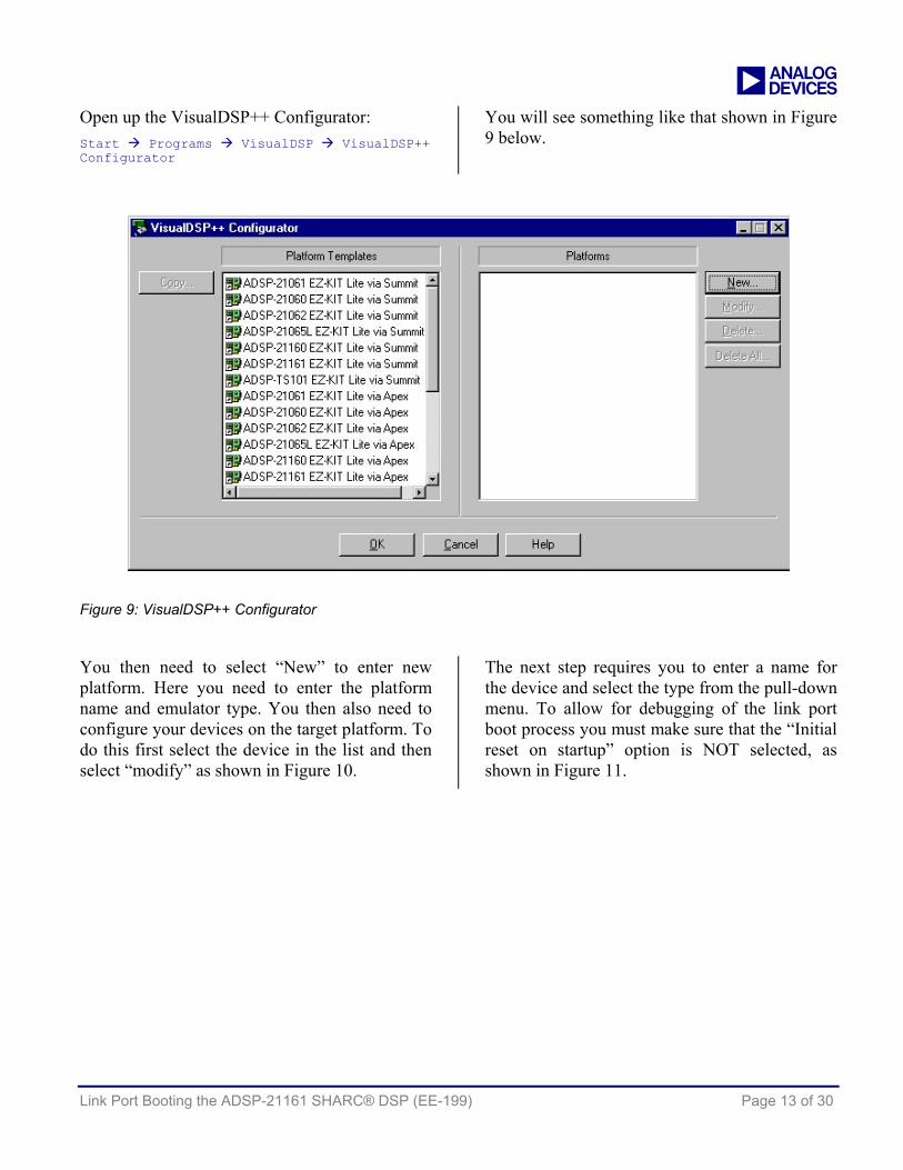
Open up the VisualDSP++ Configurator: Start Programs VisualDSP VisualDSP++ Configurator
You will see something like that shown in Figure 9 below.
Figure 9: VisualDSP++ Configurator
You then need to select “New” to enter new platform. Here you need to enter the platform name and emulator type. You then also need to configure your devices on the target platform. To do this first select the device in the list and then select “modify” as shown in Figure 10.
The next step requires you to enter a name for the device and select the type from the pull-down menu. To allow for debugging of the link port boot process you must make sure that the “Initial reset on startup” option is NOT selected, as shown in Figure 11.

a
Link Port Booting the ADSP-21161 SHARC® DSP (EE-199) Page 14 of 30
Figure 10: Platform Properties
Figure 11: Device Properties
By not selecting this option, the emulator will not generate a reset interrupt upon opening of the VisualDSP++ session, thus the emulator can be used to simply halt program execution at the point where VisualDSP++ is opened.
Now select “OK” on all the open windows to exit the VisualDSP++ Configurator.

a
Link Port Booting the ADSP-21161 SHARC® DSP (EE-199) Page 15 of 30
Creating a boot kernel for debug purposes
The ADSP-21161 link port boot kernel has some instructions included that assist in the debugging of booting problems. If the kernel is rebuilt by defining “PAUSE”, a jump(pc,0); instruction is added to the beginning of the kernel which stops the kernel from being executed.
PAUSE may be defined in 3 ways:
• Add the following to the 161_link.asm file and rebuild the 161_link project:
#define PAUSE
• From the project options window, select the “Assemble” tab and add the following line to the “Additional options:” box: -DPAUSE
• Use the –D switch at the command line to define PAUSE and generate the object file. For example: easm21k –21161 –o 161_link_debug.doj 161_link.asm -DPAUSE
Once the new kernel executable file has been created, it is then used to create a new loader file as shown in Figure 12.
Figure 12: Loader Utility

a
Link Port Booting the ADSP-21161 SHARC® DSP (EE-199) Page 16 of 30
Debugging the boot process
Once the VisualDSP++ session has been set up and the debug boot kernel has been created, we can now break into the kernel and view exactly what is going on. This allows us to debug if required. The following steps are assuming that the VisualDSP++ project that accompanies this EE-Note is being used (Master.dpj). The project allows for one ADSP-21161 to boot another with the Blink_Example loader files that are also included.
Step 1: Open up VisualDSP++ IDDE Once the device that is booting the slave ADSP-21161 via the link port has started transmitting
the newly created debug version of the loader file, open up VisualDSP++ (making sure that the emulator is connected to the target) while holding down the control (Ctrl) key on the keyboard. This is a useful technique for opening up a new or different VisualDSP++ session; otherwise the VisualDSP++ IDDE opens up with the last session that was used. This is especially useful in the case where the last session used had the “Initial reset on startup” option checked. Create your new session using the platform name that was previously created in the VisualDSP++ Configurator or select the required session from the list.
Figure 13: New session and session list
Step 2: Setting up the VisualDSP++ Environment Once VisualDSP++ connects to the target via the emulator you will be presented with something like that shown in Figure 14.
To make the debug process easier, load the symbols from the executable (file extension .dxe) file of the kernel that was used to create the loader file. This will then load in all function names and makes it far easier to determine where within the kernel execution is currently taking place.
The symbols are loaded by selecting the “Load Symbols…” option from the File pulldown menu in the VisualDSP++ IDDE.
Also for debugging the kernel we want to pay particular attention to some specific registers and their contents.
The registers of main interest to us for debugging purposes are:
• PX Registers • Loop Counters
Open up the above register windows within the VisualDSP++ IDDE so that you have something similar to that shown in Figure 15.

a
Link Port Booting the ADSP-21161 SHARC® DSP (EE-199) Page 17 of 30
Figure 14: VisualDSP++ IDDE Setup immediately after opening the kernel debug session
Figure 15: VisualDSP++ IDDE after environment setup and symbol load

a
Link Port Booting the ADSP-21161 SHARC® DSP (EE-199) Page 18 of 30
Step 3: Setup Breakpoints For this example there are two instructions at which we are interested in placing breakpoints for debugging the kernel and understanding what is going on.
The first breakpoint needs to be placed at the sixth instruction within the function “read_link_word”. This should be located at address 0x040021 in the disassembly window and the instruction should be “rts (db);”
The second breakpoint needs to be located at the first instruction within the “final_init” routine. This routine should begin at memory location 0x04003C in the disassembly window as shown within Figure 16.
Figure 16: Breakpoint location within kernel
Step 4: Starting the debug process Before we can run to the first breakpoint as shown in Figure 16, the “jump (pc,0);” instruction at 0x04005 needs to be manually edited to a “nop;”. This is done by simply right-clicking with the mouse on the instruction and then selecting edit. Change the contents to “nop;” then press the enter key. Now it is possible to run to the first breakpoint as shown in Figure 16.
Step 5: Analyzing the registers Upon reaching this breakpoint the contents of the PX registers should be analyzed. The PX register at this point holds the tag number for the initialization type of the data that is to follow. If using the Blink_Example project included with this application note then the contents of the PX register at this point is 0x00000000000E0000 as shown in Figure 17.
Figure 17: Register contents showing tag number
As the link port transfer is a 48-bit transfer loaded into the upper 48 bits of the PX register, ignore the lower 4 nibbles; these should always remain as “0000”. This is a tag word of 0xE indicating that the following data is to initialize 48-bit internal program memory (refer to Table 2).
Run to the breakpoint for a second time. Now the PX register contains the address of where the following data section is to be located as well as the number of words to be initialized. Specifically, the address is stored in PX2 and the number of words in the upper four nibbles of

a
Link Port Booting the ADSP-21161 SHARC® DSP (EE-199) Page 19 of 30
PX1 as shown in Figure 18. In this case there are 0x1E words in the section to follow.
Figure 18: Register contents showing address and word count
After running to the breakpoint for a third time, the PX register should now contain the first piece of data or instruction. The LCNTR and CURLCNTR registers are also loaded with the count value from PX1 as shown in Figure 19.
Further runs to the breakpoint will load in a new 48-bit value into the PX register for writing to memory.
Figure 19: Register contents showing first instruction
The value of the CURLCNTR register can be used as an indication as to when the next tag word will be received. Keep running to the breakpoint until the value in CURLCNTR = 0x1. On the next run to the breakpoint, the PX register contains the next tag word. In this case the next tag word is 0x4 indicating the initialization of 16-bit data memory.
Following the procedure just described it is possible to verify initialization of all the various memory sections.
In the Blink_Example project data sections for 16-bit, 32-bit, 40-bit and 64-bit data memory are initialized. Figure 20 through Figure 27 show the tag words, address and count values as well as where the data is located within the PX register for these various formats.
You will notice that when it comes to a data section that has an initialization type of zero (refer to Table 2 for details), that the data immediately following the address and word count is not 0x000000000000, but actually the tag number for the next section. Instead of large arrays of zeros being stored in the loader file, the actual kernel application initializes the section by writing zeros to the relevant locations. This results in a smaller loader file being generated thus requiring less memory storage, especially for applications that require large zero initialization arrays. An example of this is shown in Figure 21. In this figure the tag word is 0x1, which indicates initialization to 0x0000 of 16-bit internal data memory. The word following the tag number contains the address and number of words. The next 48-word received through the link port is the tag number of the next data section as shown in Figure 22(a).
Figure 28 shows the receiving of the Final Init tag word and also that RTI instruction that is used by the final init routine to overwrite the link port interrupt vector that was required for the booting process.

a
Link Port Booting the ADSP-21161 SHARC® DSP (EE-199) Page 20 of 30
(a) Tag number
(b) Address and word count
(c) Data alignment within PX register
Figure 20: 16-bit data initialization
(a) Tag number
(b) Address and word count
Figure 21: 16-bit data zero initialization
(a) Tag number
(b) Address and word count
(c) Data alignment within PX register
Figure 22: 32-bit data initialization

a
Link Port Booting the ADSP-21161 SHARC® DSP (EE-199) Page 21 of 30
(a) Tag number
(b) Address and word count
Figure 23: 32-bit data zero initialization
(a) Tag number
(b) Address and word count
(c) Data alignment within PX register
Figure 24: 40-bit data initialization
(a) Tag number
(b) Address and word count
Figure 25: 40-bit data zero initialization

a
Link Port Booting the ADSP-21161 SHARC® DSP (EE-199) Page 22 of 30
(a) Tag number
(b) Address and word count
(c) Lower 32-bits data alignment within PX register
(d) Upper 32-bits data alignment within PX register
Figure 26: 64-bit data initialization
(a) Tag number
(b) Address and word count
Figure 27: 64-bit data zero initialization
(a) Tag number
(b) Op-code for RTI instruction. Stored for use later by the kernel
Figure 28: Final Init

a
Link Port Booting the ADSP-21161 SHARC® DSP (EE-199) Page 23 of 30
Once execution reaches the FINAL_INIT routine then all that is left is to overwrite the first 256 instructions with the required interrupt vector initialization. It is best to run through this routine rather than single step. This is largely down to the fact that the DMA is set up and then the core goes into an idle state. Single stepping at this point may cause a problem due to the emulation interrupt. After running from the FINAL_INIT routine, the final application should now be fully loaded into the processor and executing as normal.
If problems are still being experienced and yet there appears to be no problem up until reaching the FINAL_INIT routine then we need to be able to successfully determine that the final 256-word write of the interrupt vector table is occurring correctly. The best method of verifying this is to place a jump(pc,0); command within the reset interrupt vector before the jump to main program execution.
If programming in C/C++, this would require an alteration to the interrupt vector table that is used by the VisualDSP++ C run-time environment. The files in which the interrupt vector tables are initialized are:
161_hdr.asm and 161_cpp_hdr.asm depending whether the project is created for the C or C++ environment.
These files are located in the following directory if installation of VisualDSP++ was to the default directory. C:\ Program Files \ Analog Devices \ VisualDSP \ 211xx\ lib \ src\ crt_src
Figure 29 shows the alteration required to the reset interrupt vector in the two files.
___lib_RSTI: NOP; JUMP(PC,0); JUMP ___lib_start; NOP;
Figure 29: Alteration to Reset interrupt Vector for debugging purposes
Rather than modify the original files. Copy the required file to your project folder and simply add this file to the project. This way the run time set up that you have just added to the project will be used instead of the original.
In order for the project to build properly with the addition of the 161_hdr.asm file to your project, you will also need to add an additional include directory to the assemble tab of the project options. The directory you need to add is as follows: C:\ Program Files \ Analog Devices \ VisualDSP \ 211xx\ lib \ src\ libc_src
You will also need to select the “Both” option from the Behavior section of the Assemble tab in the project options as shown in Figure 30.
This modification will enable you to verify that the first 256 instructions are overwritten correctly as execution remains in the reset interrupt vector. If you halt the core and you are not sitting on the jump(pc,0); instruction then some problem has occurred during the overwriting of the first 256 memory locations. If this is the case make sure that the FINAL_INIT routine has not been altered from the original in any way, also make sure that your tools are fully up to date. As VisualDSP++ advances, changes are required to the kernels. It is important that the kernel is suitable for the version of VisualDSP++ that is being used. Please refer to VisualDSP++™ Tools Required for further details.

a
Link Port Booting the ADSP-21161 SHARC® DSP (EE-199) Page 24 of 30
Figure 30: Assemble options for additional debug

a
Link Port Booting the ADSP-21161 SHARC® DSP (EE-199) Page 25 of 30
Appendix 1: Blink_Example Source code
#include <def21161.h> #define JINX 0x1FF000 #define PAUSE 0xfffFFF /****************************************************************************/ /**** The following data sections have no real functionality but have ****/ /**** been included into the project for demonstration purposes. ****/ /**** They have been included to show how a user can easily propogate ****/ /**** from one loader file tag section to the next when debugging Link ****/ /**** port boot applications.Refer to Debugging Guidlines in EE-199 for ****/ /**** further details. ****/ /****************************************************************************/ // The following data section declares 16-bit initialized data memory. // This results in a link port loader tag of 0x4. // Refer to figure 20 in EE-199 to see how this data section // is loaded into internal memory. .section /dm seg_dm_data16; .var tag_word_0x4[16] = {0x1234, 0x1111, 0x2222, 0x3333, 0x4444, 0x5555, 0x6666, 0x7777, 0x8888, 0x9999, 0xaaaa, 0xbbbb, 0xcccc, 0xdddd, 0xeeee, 0xffff}; // The following data section declares 16-bit zero-init data memory. // This results in a link port loader tag of 0x1. // Refer to figure 21 in EE-199 to see how this data section // is loaded into internal memory. .var tag_word_0x1[16]; // The following data section declares 32-bit initialized data memory. // This results in a link port loader tag of 0x5. // Refer to figure 22 in EE-199 to see how this data section // is loaded into internal memory. .section /dm seg_dm_data32; .var tag_word_0x5[16] = {0x12345678, 0x11111111, 0x22222222, 0x33333333, 0x44444444, 0x55555555, 0x66666666, 0x77777777, 0x88888888, 0x99999999, 0xaaaaaaaa, 0xbbbbbbbb, 0xcccccccc, 0xdddddddd, 0xeeeeeeee, 0xffffffff}; // The following data section declares 32-bit zero-init data memory. // This results in a link port loader tag of 0x1. // Refer to figure 23 in EE-199 to see how this data section // is loaded into internal memory. .var tag_word_0x2[16]; // The following data section declares 40-bit initialized data memory. // This results in a link port loader tag of 0x6. // Refer to figure 24 in EE-199 to see how this data section // is loaded into internal memory. .section /dm seg_dm_data40; .var tag_word_0x6[16] = {0x123456789a, 0x1111111111, 0x2222222222, 0x3333333333, 0x4444444444, 0x5555555555, 0x6666666666, 0x7777777777, 0x8888888888, 0x9999999999, 0xaaaaaaaaaa, 0xbbbbbbbbbb, 0xcccccccccc, 0xdddddddddd, 0xeeeeeeeeee, 0xffffffffff}; // The following data section declares 40-bit zero-init data memory.

a
Link Port Booting the ADSP-21161 SHARC® DSP (EE-199) Page 26 of 30
// This results in a link port loader tag of 0x3. // Refer to figure 25 in EE-199 to see how this data section // is loaded into internal memory. .var tag_word_0x3[16]; // The following data section declares 64-bit initialized data memory. // This results in a link port loader tag of 0x6. // Refer to figure 26 in EE-199 to see how this data section // is loaded into internal memory. .section /dm seg_dm_data64; .var tag_word_0x10[16] = {0x9abcdef0, 0x12345678, 0x33333333, 0x22222222, 0x55555555, 0x44444444, 0x77777777, 0x66666666, 0x99999999, 0x88888888, 0xbbbbbbbb, 0xaaaaaaaa, 0xdddddddd, 0xcccccccc, 0xffffffff, 0xeeeeeeee}; // The following data section declares 64-bit zero-init data memory. // This results in a link port loader tag of 0x3. // Refer to figure 27 in EE-199 to see how this data section // is loaded into internal memory. .var tag_word_0xF[16]; .section /pm seg_pm_code; .global __main; __main: r1=0xff00; dm(IOFLAG)=r1; // set flags as outputs r2=-3; __wayback: // count up lcntr = 9; do __up until lce; r0 = DM(IOFLAG); r0 = btgl r0 by r1; // toggle flag r1 r0 = btgl r0 by r2; // toggle flag r1 DM(IOFLAG) = r0; lcntr=JINX; do __delay until lce; //wait __delay: nop; r1 = r1 + 1; // increment which flag is toggled __up: r2 = r2 + 1; // count down lcntr = 9; do __down until lce; r1 = r1 - 1; // increment which flag is toggled r2 = r2 - 1; r0 = DM(IOFLAG); r0 = btgl r0 by r1; // toggle flag r1 r0 = btgl r0 by r2; // toggle flag r1 DM(IOFLAG) = r0; lcntr=JINX; do __delay2 until lce; // wait __delay2:nop; __down: nop; lcntr = PAUSE; do __stylee until lce; __stylee: nop; jump __wayback; __main.end:

a
Link Port Booting the ADSP-21161 SHARC® DSP (EE-199) Page 27 of 30
Appendix 2: Master Source Code
/*********************************************************************************/ /* ADSP-21161 Lite Link port boot example */ /* Code accompaniment to EE-199 Link Port Booting the ADSP-21161 */ /* Written by Andrew Caldwell */ /* European DSP Applications Engineer */ /* */ /* Description: */ /* This program requires two ADSP-21161 EZ-KIT Lite development boards and */ /* link port cable to attach the two boards. It may also be used in a */ /* master DSP in an ADSP-21161 MP cluster. */ /* */ /* The file to be booted is a simple blink example that flashes LED */ /* 2,3,4,5,6,and 7 on the ADSP-21161N EZ-KIT Lite Evaluation Platform. */ /* These LEDs are connected to flags 9, 8, 7, 6, 5 and 4 respectively. */ /* */ /* The defined value "size" refers to the number of 16 bit words contained */ /* in the loader file. This is all that requires to be altered to boot with */ /* various loader files. */ /* */ /* The loader file to be included can be built using either the ASCII or */ /* the Include file format, the example works with both. */ /* */ /*********************************************************************************/ #include "def21161.h" #include "defines.h" .global __main; // Each 16-bit word of the loader file is stored in the lower 16 bits of 32-bit // data memory .section/dm seg_dmda; .var _ldr_source[size] = "knightrider_link_sdram.ldr"; .section/pm seg_pmco; __main: // Clear link control registers r1 = 0x0; dm(LCTL) = r1; // The 16 bit words from the ldr_source buffer must be packed into a 48-bit // instruction before being transmitted. The loader file is of the format that the // first 16-bit word is the least significant 16 bit words of the 48-bit // instruction, the next 16-bit word is the middle 16-bits of the 48-bit // instruction and the third 16-bit word is the 16 most significant bits of the // 48-bit instruction. This is the same for ASCII or Include loader file formats. B0 = _ldr_source; M0 = 1; L0 = 0; // Declare base, modify and length values // of buffer r0 = LAB1 | L0EN | L0TRAN |L0EXT; dm(LCTL) = r0; // This routine calls the tx_instructions procedure passing the kernel_count of 256 // to the routine __transmit_kernel: call __tx_instructions (db); r4 = kernel_count; nop; __transmit_kernel.end:

a
Link Port Booting the ADSP-21161 SHARC® DSP (EE-199) Page 28 of 30
// This routine calls the tx_instructions procedure passing the count value to the // routine __transmit_code: call __tx_instructions (db); r4 = count; nop; __transmit_code.end: // End of program __stay: jump __stay; __main.end: // The tx_instructions routine is set up to run either kernel_count or count times // to transmit either the first 256 words or the remainder of the code. // The loop consists of three parts. The first is test_lbuf. This reads the value // of the link port common control register to check if the link port buffer is // full, if the buffer is full then it continually monitors this register until the // buffer is not full. If the buffer is not full then three 16-bit words are read // and packed into the px register using px1 and px2 to create the 48-bit // instruction to be transmitted. __tx_instructions: lcntr = r4, do __tx_word until lce; // set loop counter to 256 to transmit
// kernel __test_lbuf: r3 = dm(LCTL); // read LCTL register r3 = ASHIFT r3 by LCTL_SHIFT; // Shift so correct LBUF status can be
// compared to 0x3 (full) r2 = 0x3; comp(r2, r3); if eq jump __test_lbuf; // Check LBUF status, if full then
// test_lbuf, if not then create // instruction
__pack_word: r0 = dm(i0, m0); // Read first 16-bit word r0 = LSHIFT r0 by 16; // Shift 16 bits to MSBs of r0 to be
// loaded into px1 px1 = r0; // LSBs of px1 are dropped when reading px r0 = dm(i0, m0); // Read middle 16 bits of instruction r1 = dm(i0, m0); // Read upper 16 bits of instruction r0 = r0 OR LSHIFT r1 by 16; // Create upper 32 bits of instruction px2 = r0; // Store in px2 __tx_word: pm(tx_buffer) = px; // Transmit contents of px. 48 bits are
// transmitted and not 64 (16 LSBs // dropped)
rts; __tx_instructions.end:

a
Link Port Booting the ADSP-21161 SHARC® DSP (EE-199) Page 29 of 30
References [1] ADSP-21161 SHARC® DSP Hardware Reference. Third Edition, May 2002. Analog Devices, Inc.
[2] ADSP-21161N SHARC® DSP Datasheet. Revision A, May 2003, Analog Devices, Inc.
[3] VisualDSP++™ 3.0 Linker and Utilities Manual for ADSP-21xxx DSPs. Revision 4.0, January 2003. Analog Devices, Inc.
Document History
Version Description
August 19, 2003 by A.Caldwell Initial Release