Engine Management...Engine Management 2 ACRONYMS The following is a list of acronyms used throughout...
158
Engine Management
Transcript of Engine Management...Engine Management 2 ACRONYMS The following is a list of acronyms used throughout...

Engine Management

Engine Management

Engine Management
I
TABLE OF CONTENTS
INTRODUCTION AND OBJECTIVES 1. . . . . . . . . . . . . . . . . . . . . . . . . . . . . . . . . . . . . . . . . . . . ACRONYMS 2. . . . . . . . . . . . . . . . . . . . . . . . . . . . . . . . . . . . . . . . . . . . . . . . . . . . . . . . . . . . . . . . . . . . POWERTRAIN CONTROL MODULE (PCM) – GENERAL INFORMATION 4. . . . . . . . .
SINGLE BOARD ENGINE CONTROLLER (SBEC) – 1992–1995 5. . . . . . . . . . . . . . . . VIPER IGNITION CONTROLLER (VIC) 6. . . . . . . . . . . . . . . . . . . . . . . . . . . . . . . . . . . . . . . .
Inputs 6. . . . . . . . . . . . . . . . . . . . . . . . . . . . . . . . . . . . . . . . . . . . . . . . . . . . . . . . . . . . . . . . . . Outputs 6. . . . . . . . . . . . . . . . . . . . . . . . . . . . . . . . . . . . . . . . . . . . . . . . . . . . . . . . . . . . . . . .
JEEP/TRUCK ENGINE CONTROLLER (JTEC) – 1996–2000 8. . . . . . . . . . . . . . . . . . JTEC Learning Functions 9. . . . . . . . . . . . . . . . . . . . . . . . . . . . . . . . . . . . . . . . . . . . . . .
SPEED DENSITY 10. . . . . . . . . . . . . . . . . . . . . . . . . . . . . . . . . . . . . . . . . . . . . . . . . . . . . . . . . . FUEL DELIVERY SYSTEM 12. . . . . . . . . . . . . . . . . . . . . . . . . . . . . . . . . . . . . . . . . . . . . . . . . EMISSIONS SYSTEM 12. . . . . . . . . . . . . . . . . . . . . . . . . . . . . . . . . . . . . . . . . . . . . . . . . . . . . . IDLE CONTROL SYSTEMS 13. . . . . . . . . . . . . . . . . . . . . . . . . . . . . . . . . . . . . . . . . . . . . . . . . CHARGING CONTROL SYSTEMS 13. . . . . . . . . . . . . . . . . . . . . . . . . . . . . . . . . . . . . . . . . . .
1996 Viper Roadster 13. . . . . . . . . . . . . . . . . . . . . . . . . . . . . . . . . . . . . . . . . . . . . . . . . . . 1996 Viper Coupe/1997 All Vipers 13. . . . . . . . . . . . . . . . . . . . . . . . . . . . . . . . . . . . .
ENGINE COOLING CONTROL SYSTEMS 14. . . . . . . . . . . . . . . . . . . . . . . . . . . . . . . . . . . A/C CONTROL SYSTEMS 14. . . . . . . . . . . . . . . . . . . . . . . . . . . . . . . . . . . . . . . . . . . . . . . . . . TRANSMISSION CONTROL 14. . . . . . . . . . . . . . . . . . . . . . . . . . . . . . . . . . . . . . . . . . . . . . . . .
FUEL DELIVERY COMPONENTS 15. . . . . . . . . . . . . . . . . . . . . . . . . . . . . . . . . . . . . . . . . . . . . . FUEL TANK 15. . . . . . . . . . . . . . . . . . . . . . . . . . . . . . . . . . . . . . . . . . . . . . . . . . . . . . . . . . . . . . . FUEL PUMP MODULE 16. . . . . . . . . . . . . . . . . . . . . . . . . . . . . . . . . . . . . . . . . . . . . . . . . . . . .
Check Valve Operation 17. . . . . . . . . . . . . . . . . . . . . . . . . . . . . . . . . . . . . . . . . . . . . . . . . FUEL PRESSURE REGULATOR 18. . . . . . . . . . . . . . . . . . . . . . . . . . . . . . . . . . . . . . . . . . . .
Fuel Flow 18. . . . . . . . . . . . . . . . . . . . . . . . . . . . . . . . . . . . . . . . . . . . . . . . . . . . . . . . . . . . . . FUEL PUMP RELAY 20. . . . . . . . . . . . . . . . . . . . . . . . . . . . . . . . . . . . . . . . . . . . . . . . . . . . . . . . FUEL INJECTORS 22. . . . . . . . . . . . . . . . . . . . . . . . . . . . . . . . . . . . . . . . . . . . . . . . . . . . . . . . . FUEL FILTER 23. . . . . . . . . . . . . . . . . . . . . . . . . . . . . . . . . . . . . . . . . . . . . . . . . . . . . . . . . . . . . . FUEL LINES AND RAIL 24. . . . . . . . . . . . . . . . . . . . . . . . . . . . . . . . . . . . . . . . . . . . . . . . . . . .
Fuel Lines 24. . . . . . . . . . . . . . . . . . . . . . . . . . . . . . . . . . . . . . . . . . . . . . . . . . . . . . . . . . . . . Fuel Rail 24. . . . . . . . . . . . . . . . . . . . . . . . . . . . . . . . . . . . . . . . . . . . . . . . . . . . . . . . . . . . . .
THROTTLE BODY 26. . . . . . . . . . . . . . . . . . . . . . . . . . . . . . . . . . . . . . . . . . . . . . . . . . . . . . . . . POWERTRAIN CONTROL MODULE 28. . . . . . . . . . . . . . . . . . . . . . . . . . . . . . . . . . . . . . . . . . . .
POWER SUPPLIES AND GROUNDS (JTEC) 28. . . . . . . . . . . . . . . . . . . . . . . . . . . . . . . . . POWER SUPPLIES AND GROUNDS (SBEC) 30. . . . . . . . . . . . . . . . . . . . . . . . . . . . . . . . . DATA LINK CONNECTOR (DLC) 32. . . . . . . . . . . . . . . . . . . . . . . . . . . . . . . . . . . . . . . . . . . .

Engine Management
II
TABLE OF CONTENTS (CONTINUED)
FUEL INJECTION SYSTEM – PCM INPUTS 34. . . . . . . . . . . . . . . . . . . . . . . . . . . . . . . . . . . CRANKSHAFT POSITION SENSOR (CKP) 34. . . . . . . . . . . . . . . . . . . . . . . . . . . . . . . . . .
Crankshaft Position Sensor Service 39. . . . . . . . . . . . . . . . . . . . . . . . . . . . . . . . . . . . CAMSHAFT POSITION SENSOR (CMP) (JTEC) 40. . . . . . . . . . . . . . . . . . . . . . . . . . . . .
Cam/Crank Diagnosis 43. . . . . . . . . . . . . . . . . . . . . . . . . . . . . . . . . . . . . . . . . . . . . . . . Camshaft Position Sensor Service 43. . . . . . . . . . . . . . . . . . . . . . . . . . . . . . . . . . . . .
CAMSHAFT POSITION SENSOR (CMP) SBEC) 44. . . . . . . . . . . . . . . . . . . . . . . . . . . . . Injection/Ignition Timing 48. . . . . . . . . . . . . . . . . . . . . . . . . . . . . . . . . . . . . . . . . . . . . Synchronization 49. . . . . . . . . . . . . . . . . . . . . . . . . . . . . . . . . . . . . . . . . . . . . . . . . . . . . .
MANIFOLD ABSOLUTE PRESSURE (MAP) SENSOR 50. . . . . . . . . . . . . . . . . . . . . . . . Map Sensor Diagnostics 55. . . . . . . . . . . . . . . . . . . . . . . . . . . . . . . . . . . . . . . . . . . . . . Map Sensor Limp–In 55. . . . . . . . . . . . . . . . . . . . . . . . . . . . . . . . . . . . . . . . . . . . . . . . . . Component Locations 56. . . . . . . . . . . . . . . . . . . . . . . . . . . . . . . . . . . . . . . . . . . . . . . . .
THROTTLE POSITION SENSOR (TPS) 57. . . . . . . . . . . . . . . . . . . . . . . . . . . . . . . . . . . . . . TPS PROGRAMS 60. . . . . . . . . . . . . . . . . . . . . . . . . . . . . . . . . . . . . . . . . . . . . . . . . . . . . . . . . .
Idle 60. . . . . . . . . . . . . . . . . . . . . . . . . . . . . . . . . . . . . . . . . . . . . . . . . . . . . . . . . . . . . . . . . . Off–Idle 60. . . . . . . . . . . . . . . . . . . . . . . . . . . . . . . . . . . . . . . . . . . . . . . . . . . . . . . . . . . . . . . Acceleration 61. . . . . . . . . . . . . . . . . . . . . . . . . . . . . . . . . . . . . . . . . . . . . . . . . . . . . . . . . . Wide Open Throttle (WOT) 61. . . . . . . . . . . . . . . . . . . . . . . . . . . . . . . . . . . . . . . . . . . . Deceleration 61. . . . . . . . . . . . . . . . . . . . . . . . . . . . . . . . . . . . . . . . . . . . . . . . . . . . . . . . . . Wide Open Throttle Fuel Cut–Off During Cranking 61. . . . . . . . . . . . . . . . . . . . . TPS Diagnostics 62. . . . . . . . . . . . . . . . . . . . . . . . . . . . . . . . . . . . . . . . . . . . . . . . . . . . . . TPS Limp–In 62. . . . . . . . . . . . . . . . . . . . . . . . . . . . . . . . . . . . . . . . . . . . . . . . . . . . . . . . . .
ENGINE COOLANT TEMPERATURE (ECT) SENSOR 64. . . . . . . . . . . . . . . . . . . . . . . . 1996 Coupe/1997 and Up All 65. . . . . . . . . . . . . . . . . . . . . . . . . . . . . . . . . . . . . . . . . ECT Operation 68. . . . . . . . . . . . . . . . . . . . . . . . . . . . . . . . . . . . . . . . . . . . . . . . . . . . . . . . ECT Sensor Diagnostics 70. . . . . . . . . . . . . . . . . . . . . . . . . . . . . . . . . . . . . . . . . . . . . . . ECT Sensor Limp–In 70. . . . . . . . . . . . . . . . . . . . . . . . . . . . . . . . . . . . . . . . . . . . . . . . . .
INTAKE AIR TEMPERATURE (IAT) SENSOR 72. . . . . . . . . . . . . . . . . . . . . . . . . . . . . . . . SBEC IAT Operation 74. . . . . . . . . . . . . . . . . . . . . . . . . . . . . . . . . . . . . . . . . . . . . . . . . . IAT Sensor Diagnostics 74. . . . . . . . . . . . . . . . . . . . . . . . . . . . . . . . . . . . . . . . . . . . . . . IAT Sensor Limp–In 74. . . . . . . . . . . . . . . . . . . . . . . . . . . . . . . . . . . . . . . . . . . . . . . . . . .
SENSED BATTERY VOLTAGE 75. . . . . . . . . . . . . . . . . . . . . . . . . . . . . . . . . . . . . . . . . . . . . Fuel Injectors 75. . . . . . . . . . . . . . . . . . . . . . . . . . . . . . . . . . . . . . . . . . . . . . . . . . . . . . . . . Charging – 1996 Coupe/1997–2000 All 75. . . . . . . . . . . . . . . . . . . . . . . . . . . . . . . . Charging – 1996 Viper Roadster 75. . . . . . . . . . . . . . . . . . . . . . . . . . . . . . . . . . . . . . .
Engine Management
III
TABLE OF CONTENTS (CONTINUED)
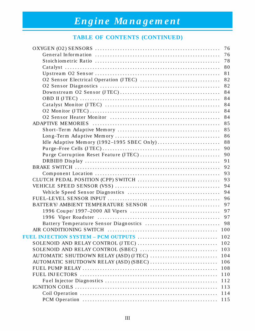
OXYGEN (O2) SENSORS 76. . . . . . . . . . . . . . . . . . . . . . . . . . . . . . . . . . . . . . . . . . . . . . . . . . General Information 76. . . . . . . . . . . . . . . . . . . . . . . . . . . . . . . . . . . . . . . . . . . . . . . . . . Stoichiometric Ratio 78. . . . . . . . . . . . . . . . . . . . . . . . . . . . . . . . . . . . . . . . . . . . . . . . . . Catalyst 80. . . . . . . . . . . . . . . . . . . . . . . . . . . . . . . . . . . . . . . . . . . . . . . . . . . . . . . . . . . . . . Upstream O2 Sensor 81. . . . . . . . . . . . . . . . . . . . . . . . . . . . . . . . . . . . . . . . . . . . . . . . . . O2 Sensor Electrical Operation (JTEC) 82. . . . . . . . . . . . . . . . . . . . . . . . . . . . . . . . O2 Sensor Diagnostics 82. . . . . . . . . . . . . . . . . . . . . . . . . . . . . . . . . . . . . . . . . . . . . . . . Downstream O2 Sensor (JTEC) 84. . . . . . . . . . . . . . . . . . . . . . . . . . . . . . . . . . . . . . . . OBD II (JTEC) 84. . . . . . . . . . . . . . . . . . . . . . . . . . . . . . . . . . . . . . . . . . . . . . . . . . . . . . . . Catalyst Monitor (JTEC) 84. . . . . . . . . . . . . . . . . . . . . . . . . . . . . . . . . . . . . . . . . . . . . . O2 Monitor (JTEC) 84. . . . . . . . . . . . . . . . . . . . . . . . . . . . . . . . . . . . . . . . . . . . . . . . . . . . O2 Sensor Heater Monitor 84. . . . . . . . . . . . . . . . . . . . . . . . . . . . . . . . . . . . . . . . . . . .
ADAPTIVE MEMORIES 85. . . . . . . . . . . . . . . . . . . . . . . . . . . . . . . . . . . . . . . . . . . . . . . . . . . Short–Term Adaptive Memory 85. . . . . . . . . . . . . . . . . . . . . . . . . . . . . . . . . . . . . . . . . Long–Term Adaptive Memory 86. . . . . . . . . . . . . . . . . . . . . . . . . . . . . . . . . . . . . . . . . . Idle Adaptive Memory (1992–1995 SBEC Only) 88. . . . . . . . . . . . . . . . . . . . . . . . . Purge–Free Cells (JTEC) 90. . . . . . . . . . . . . . . . . . . . . . . . . . . . . . . . . . . . . . . . . . . . . . . Purge Corruption Reset Feature (JTEC) 90. . . . . . . . . . . . . . . . . . . . . . . . . . . . . . . . DRBIII Display 91. . . . . . . . . . . . . . . . . . . . . . . . . . . . . . . . . . . . . . . . . . . . . . . . . . . . . .
BRAKE SWITCH 92. . . . . . . . . . . . . . . . . . . . . . . . . . . . . . . . . . . . . . . . . . . . . . . . . . . . . . . . . . Component Location 93. . . . . . . . . . . . . . . . . . . . . . . . . . . . . . . . . . . . . . . . . . . . . . . . . .
CLUTCH PEDAL POSITION (CPP) SWITCH 93. . . . . . . . . . . . . . . . . . . . . . . . . . . . . . . . . VEHICLE SPEED SENSOR (VSS) 94. . . . . . . . . . . . . . . . . . . . . . . . . . . . . . . . . . . . . . . . . .
Vehicle Speed Sensor Diagnostics 94. . . . . . . . . . . . . . . . . . . . . . . . . . . . . . . . . . . . . FUEL–LEVEL SENSOR INPUT 96. . . . . . . . . . . . . . . . . . . . . . . . . . . . . . . . . . . . . . . . . . . . . BATTERY/AMBIENT TEMPERATURE SENSOR 97. . . . . . . . . . . . . . . . . . . . . . . . . . . .
1996 Coupe/1997–2000 All Vipers 97. . . . . . . . . . . . . . . . . . . . . . . . . . . . . . . . . . . . 1996 Viper Roadster 97. . . . . . . . . . . . . . . . . . . . . . . . . . . . . . . . . . . . . . . . . . . . . . . . . Battery Temperature Sensor Diagnostics 98. . . . . . . . . . . . . . . . . . . . . . . . . . . . . .
AIR CONDITIONING SWITCH 100. . . . . . . . . . . . . . . . . . . . . . . . . . . . . . . . . . . . . . . . . . . . FUEL INJECTION SYSTEM – PCM OUTPUTS 102. . . . . . . . . . . . . . . . . . . . . . . . . . . . . . . .
SOLENOID AND RELAY CONTROL (JTEC) 102. . . . . . . . . . . . . . . . . . . . . . . . . . . . . . . . SOLENOID AND RELAY CONTROL (SBEC) 103. . . . . . . . . . . . . . . . . . . . . . . . . . . . . . . AUTOMATIC SHUTDOWN RELAY (ASD) (JTEC) 104. . . . . . . . . . . . . . . . . . . . . . . . . . . AUTOMATIC SHUTDOWN RELAY (ASD) (SBEC) 106. . . . . . . . . . . . . . . . . . . . . . . . . . . FUEL PUMP RELAY 108. . . . . . . . . . . . . . . . . . . . . . . . . . . . . . . . . . . . . . . . . . . . . . . . . . . . . . FUEL INJECTORS 110. . . . . . . . . . . . . . . . . . . . . . . . . . . . . . . . . . . . . . . . . . . . . . . . . . . . . . .
Fuel Injector Diagnostics 112. . . . . . . . . . . . . . . . . . . . . . . . . . . . . . . . . . . . . . . . . . . . . IGNITION COILS 113. . . . . . . . . . . . . . . . . . . . . . . . . . . . . . . . . . . . . . . . . . . . . . . . . . . . . . . . .
Coil Operation 114. . . . . . . . . . . . . . . . . . . . . . . . . . . . . . . . . . . . . . . . . . . . . . . . . . . . . . . PCM Operation 115. . . . . . . . . . . . . . . . . . . . . . . . . . . . . . . . . . . . . . . . . . . . . . . . . . . . . .
Engine Management
IV
TABLE OF CONTENTS (CONTINUED)
IDLE AIR CONTROL (IAC) STEPPER MOTOR 116. . . . . . . . . . . . . . . . . . . . . . . . . . . . . . Description 116. . . . . . . . . . . . . . . . . . . . . . . . . . . . . . . . . . . . . . . . . . . . . . . . . . . . . . . . . . Operation 117. . . . . . . . . . . . . . . . . . . . . . . . . . . . . . . . . . . . . . . . . . . . . . . . . . . . . . . . . . . IAC Stepper Motor Program 122. . . . . . . . . . . . . . . . . . . . . . . . . . . . . . . . . . . . . . . . . . Target Idle 123. . . . . . . . . . . . . . . . . . . . . . . . . . . . . . . . . . . . . . . . . . . . . . . . . . . . . . . . . . . IAC Motor Position 123. . . . . . . . . . . . . . . . . . . . . . . . . . . . . . . . . . . . . . . . . . . . . . . . . . . IAC Stepper Motor Service 123. . . . . . . . . . . . . . . . . . . . . . . . . . . . . . . . . . . . . . . . . . . IAC Diagnostics (JTEC) 123. . . . . . . . . . . . . . . . . . . . . . . . . . . . . . . . . . . . . . . . . . . . . .
RADIATOR FAN RELAYS 124. . . . . . . . . . . . . . . . . . . . . . . . . . . . . . . . . . . . . . . . . . . . . . . . . 1992–1995 SBEC Radiator Fans 125. . . . . . . . . . . . . . . . . . . . . . . . . . . . . . . . . . . . . 1996–2000 JTEC Radiator Fans 128. . . . . . . . . . . . . . . . . . . . . . . . . . . . . . . . . . . . . . Radiator Fan ON Relay 128. . . . . . . . . . . . . . . . . . . . . . . . . . . . . . . . . . . . . . . . . . . . . . . Radiator Fan Low/High Relay 128. . . . . . . . . . . . . . . . . . . . . . . . . . . . . . . . . . . . . . . .
GENERATOR FIELD CONTROL – 1992–1996 ROADSTER 130. . . . . . . . . . . . . . . . . GENERATOR FIELD CONTROL – EXCEPT 1992–1996 ROADSTER 130. . . . . . . . CHARGING SYSTEM INDICATOR LIGHT – 1992–1996 ROADSTER 132. . . . . . . . CHARGING SYSTEM INDICATOR LIGHT – 1996 COUPE, 1997–2000 ALL 132. . TACHOMETER 132. . . . . . . . . . . . . . . . . . . . . . . . . . . . . . . . . . . . . . . . . . . . . . . . . . . . . . . . . . REVERSE LOCKOUT SOLENOID 133. . . . . . . . . . . . . . . . . . . . . . . . . . . . . . . . . . . . . . . . . SKIP SHIFT SOLENOID AND INDICATOR LAMP 133. . . . . . . . . . . . . . . . . . . . . . . . . . MALFUNCTION INDICATOR LAMP (MIL) 134. . . . . . . . . . . . . . . . . . . . . . . . . . . . . . . . . .
Trip Definition – 1996–2000 Only 135. . . . . . . . . . . . . . . . . . . . . . . . . . . . . . . . . . . . EVAPORATIVE PURGE SOLENOID 136. . . . . . . . . . . . . . . . . . . . . . . . . . . . . . . . . . . . . . . LEAK DETECTION PUMP SOLENOID (STARTING IN 1998) 136. . . . . . . . . . . . . . . .
EMISSIONS CONTROL SYSTEM 138. . . . . . . . . . . . . . . . . . . . . . . . . . . . . . . . . . . . . . . . . . . . EVAPORATIVE EMISSION CONTROL 138. . . . . . . . . . . . . . . . . . . . . . . . . . . . . . . . . . . . .
Fuel Filler Cap 140. . . . . . . . . . . . . . . . . . . . . . . . . . . . . . . . . . . . . . . . . . . . . . . . . . . . . . . Rollover Valves 140. . . . . . . . . . . . . . . . . . . . . . . . . . . . . . . . . . . . . . . . . . . . . . . . . . . . . . Purge Solenoid (Bi–Level Purge) (1992–1995) 140. . . . . . . . . . . . . . . . . . . . . . . . . . Duty–Cycle Purge Solenoid (1996–2000) 141. . . . . . . . . . . . . . . . . . . . . . . . . . . . . . Fuel–Vapor Recovery System (Duty–Cycle Purge Control) 142. . . . . . . . . . . . . . On–Board Refueling Vapor Recovery (ORVR) System – 2000 142. . . . . . . . . . . Leak Detection Pump (Beginning in 1998) 143. . . . . . . . . . . . . . . . . . . . . . . . . . . .
POSITIVE CRANKCASE VENTILATION (PCV) SYSTEM (1992–1997) 144. . . . . . . . POSITIVE CRANKCASE VENTILATION (PCV) SYSTEM (1998 & LATER) 146. . . .
AIR CONDITIONING CONTROLS 148. . . . . . . . . . . . . . . . . . . . . . . . . . . . . . . . . . . . . . . . . . . . INSTRUMENT PANEL A/C SELECT SWITCH 148. . . . . . . . . . . . . . . . . . . . . . . . . . . . . . A/C REQUEST SIGNAL 148. . . . . . . . . . . . . . . . . . . . . . . . . . . . . . . . . . . . . . . . . . . . . . . . . . A/C COMPRESSOR CLUTCH RELAY 148. . . . . . . . . . . . . . . . . . . . . . . . . . . . . . . . . . . . .

Engine Management
1
INTRODUCTION AND OBJECTIVES
The Viper “Engine Management” Book contains information regarding the systemscontrolled by the Powertrain Control Module (PCM). These include fuel, emissions,charging, radiator fan, PCM–related A/C control functions, and PCM–relatedtransmission control functions.
From 1992–1995 engine controllers were SBEC PCMs with a supplemental ViperIgnition Controller (VIC). 1992–1995 Vipers were not OBDII compliant. From 1996forward, all Vipers are equipped with a Jeep Truck Engine Controller (JTEC), andare OBDII compliant.
The fuel system for all Viper engines utilizes a speed density sequential multiportfuel injection system, to deliver precise amounts of fuel to each cylinder. Fuel for allvehicles is delivered by an in–tank pump module.
All engines use a distributorless ignition system. The PCM (and VIC for 1992–1995)controls the ignition and fuel injector operation and provides outputs to fuel andignition components to promote the most efficient operation possible.
Note: Early 1997 PCMs have an eight–digit part number and operate like a 1996PCM. Later 1997 models have a 10–digit part number.
After completing the “Engine Management” book, you will understand the variousoperations of the PCM (inputs/outputs) and the operation of the fuel system.
Engine Management
2
ACRONYMS
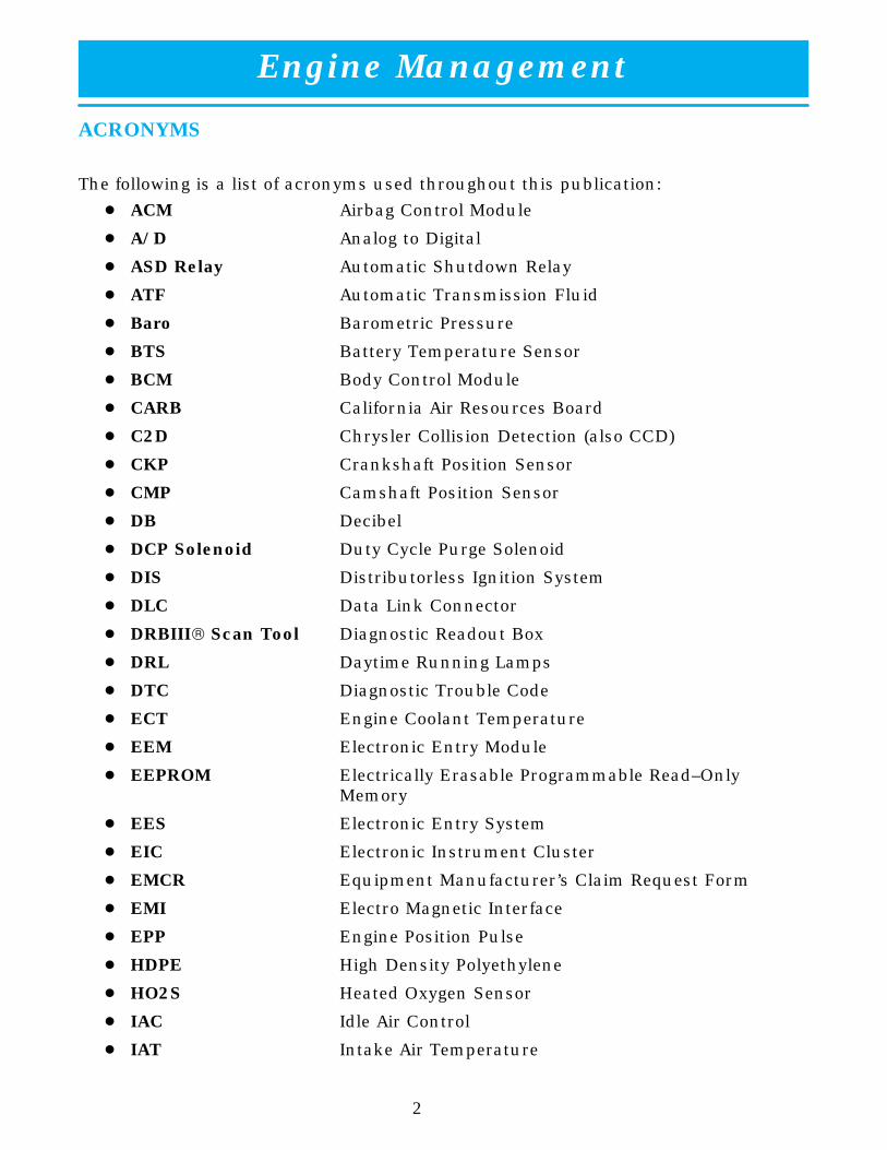
The following is a list of acronyms used throughout this publication:
� ACM Airbag Control Module
� A/D Analog to Digital
� ASD Relay Automatic Shutdown Relay
� ATF Automatic Transmission Fluid
� Baro Barometric Pressure
� BTS Battery Temperature Sensor
� BCM Body Control Module
� CARB California Air Resources Board
� C2D Chrysler Collision Detection (also CCD)
� CKP Crankshaft Position Sensor
� CMP Camshaft Position Sensor
� DB Decibel
� DCP Solenoid Duty Cycle Purge Solenoid
� DIS Distributorless Ignition System
� DLC Data Link Connector
� DRBIII Scan Tool Diagnostic Readout Box
� DRL Daytime Running Lamps
� DTC Diagnostic Trouble Code
� ECT Engine Coolant Temperature
� EEM Electronic Entry Module
� EEPROM Electrically Erasable Programmable Read–Only Memory
� EES Electronic Entry System
� EIC Electronic Instrument Cluster
� EMCR Equipment Manufacturer’s Claim Request Form
� EMI Electro Magnetic Interface
� EPP Engine Position Pulse
� HDPE High Density Polyethylene
� HO2S Heated Oxygen Sensor
� IAC Idle Air Control
� IAT Intake Air Temperature

Engine Management
3
ACRONYMS (CONTINUED)
� ICM Ignition Control Module
� ISO International Standards Organization
� JTEC Jeep/Truck Engine Controller
� LDP Leak Detection Pump
� MAP Manifold Absolute Pressure
� MDS Mopar Diagnostic System
� MIC Mechanical Instrument Cluster
� MIL Malfunction Indicator Lamp
� NTC Negative Temperature Coefficient
� OBD II On–Board Diagnostics Generation Two
� O2S Oxygen Sensor
� PCM Powertrain Control Module
� PDC Power Distribution Center
� PPA Polyphthalamide
� PTC Positive Temperature Coefficient
� RFI Radio Frequency Interface
� RIM Reaction Injection Molding
� RKE Remote Keyless Entry
� RPM Revolutions Per Minute
� RTM Resin Transfer Molding
� RTV Room Temperature Vulcanizing
� SAM Security Alarm Module
� SCI Standard Corporate Interface
� SBEC Single Board Engine Controller
� SMC Sheet Molded Compound
� SPIO Serial Peripheral Interface/Output
� TDC Top Dead Center
� TPO Thermal Plastic Olefin
� TPS Throttle Position Sensor
� VIC Viper Ignition Control Module (also ICM)
� VSS Vehicle Speed Sensor
� VTSS Vehicle Theft Security System

Engine Management
4
POWERTRAIN CONTROL MODULE (PCM) – GENERAL INFORMATION
The PCM is a digital computer that contains a microprocessor. The PCM receivesinput signals from various switches and sensors that are referred to as PCM Inputs.Based on these inputs, the PCM adjusts various engine and vehicle operationsthrough devices that are referred to as PCM Outputs. Based on inputs it receives,the PCM adjusts injector pulse width, idle speed, ignition spark advance, ignitioncoil dwell, and EVAP canister purge operation. The PCM also performs diagnostics.
The PCM used on the Viper varies, depending on the year and specific vehicleapplication. It is important to understand which PCM is used on the vehicle you areservicing because replacement controllers are model year specific with internalhardware differences. Refer to Table One for a list of vehicles along with theirspecific PCM.
Table One PCM Applications
Model Year(s) Vehicle/Application
1992 – 1994 Roadster (multi–piece intake manifold) – SBEC/VIC
1994 – 1995 Roadster (one–piece intake manifold) – SBEC/VIC
1996 Roadster – Unique JTEC
1996 – 1998 Coupe – JTEC
1997 – 1998 Roadster – JTEC
1999 – 2000 Coupe and Roadster – JTEC+

Engine Management
5
SINGLE BOARD ENGINE CONTROLLER (SBEC) – 1992–1995
The PCM, also referred to as Single Board Engine Controller (SBEC) or enginecontroller, and the Viper Ignition Controller (VIC), also referred to as the IgnitionControl Module (ICM), are located under the hood and are mounted to the right ofthe heater housing (fig. 1). This engine controller arrangement is used on Vipersfrom 1992–1995. As a running change in 1994, a revised intake manifold was used.This change required a revised SBEC calibration. The recalibrated SBEC cannot beused to service models with the previous intake manifold.
The SBEC and the VIC manage the operation of the engine control system. Theyreceive information from input sensors that monitor engine conditions. Afterprocessing this information, the SBEC and VIC control a number of outputs, whichregulate engine performance. The SBEC and VIC communicate with each otherthrough the SCI Transmit, SCI Receive, and the MUX lines of communication.
99128–001
ÁÁÁÁÁÁÁÁÁ
1
ÁÁÁÁ
2
ÁÁÁÁÁÁ
3
Figure 1 SBEC/VIC Locations
1 SBEC Engine Controller (PCM) 3 Viper Ignition Controller (VIC)
2 Heater Housing
Engine Management
6
VIPER IGNITION CONTROLLER (VIC)
Inputs
As mentioned earlier, the VIC and SBEC communicate with each other through theSCI Transmit, SCI Receive, and the MUX lines of communication. The VIC receivesinformation from the following inputs:
� Sync pickup� Reference pickup
� Vehicle speed in� Ignition
� SCI Receive
The VIC receives information from these inputs and determines when to energizethe Ignition Coils and injectors #1 and #5.
Outputs
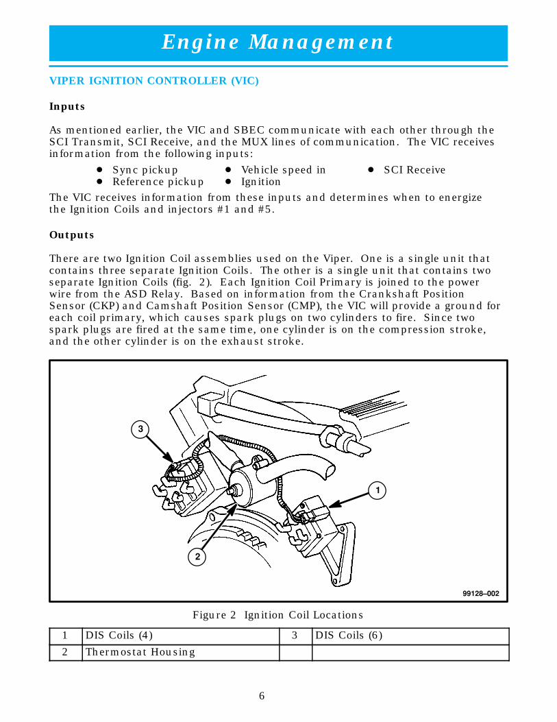
There are two Ignition Coil assemblies used on the Viper. One is a single unit thatcontains three separate Ignition Coils. The other is a single unit that contains twoseparate Ignition Coils (fig. 2). Each Ignition Coil Primary is joined to the powerwire from the ASD Relay. Based on information from the Crankshaft PositionSensor (CKP) and Camshaft Position Sensor (CMP), the VIC will provide a ground foreach coil primary, which causes spark plugs on two cylinders to fire. Since twospark plugs are fired at the same time, one cylinder is on the compression stroke,and the other cylinder is on the exhaust stroke.
99128–002
ÁÁÁÁ
1
ÁÁÁÁ
2
ÁÁÁÁ
3
Figure 2 Ignition Coil Locations
1 DIS Coils (4) 3 DIS Coils (6)
2 Thermostat Housing

Engine Management
7
The following table shows the VIC Pin number that fires the applicable coil:
Table Two VIC/Ignition Coil Firing
VIC Pin Number Fired Coil Cylinders
Pin 3 Coil #1 Cylinder #1 and #6
Pin 1 Coil #2 Cylinder #5 and #10
Pin 12 Coil #3 Cylinder #8 and #9
Pin 18 Coil #4 Cylinder #4 and #7
Pin 10 Coil #5 Cylinder #2 and #3

Engine Management
8
JEEP/TRUCK ENGINE CONTROLLER (JTEC) –1996–2000
Introduced in 1996, the Jeep/Truck Engine Controller (JTEC), also known as thePowertrain Control Module (PCM) does not require air to flow through the controllerfor cooling (fig. 3).
99128–003
Figure 3 JTEC Powertrain Control Module
The changes to the PCM from previous Chrysler controllers include:
� Increased memory:
� 2k 1996
� 4k 1997
� Increased speed at which the processor runs:
� Clock speed (8 MHz) (22MHz for JTEC+)
� 16–bit microprocessor
� Two 8–bit microprocessors
� Increased number of drivers to control outputs from 22 to 30
� Increased number of terminals in the connector from 60 to three 32–wayconnectors (96 total).
� Gold–plated, low–insertion–force terminals (new tool No. 6934 required forservicing the terminals).
� Uses an Electrically Erasable Programmable Read–Only Memory (EEPROM) onall PCMs (flashable).
� Full Range Misfire Detection (2000)

Engine Management
9
The PCM is a multiprocessor unit, containing one 16–bit microprocessor and two8–bit microprocessors. The PCM controls operation of the fuel, emissions, charging,idle, radiator fan, and air conditioning systems. This is accomplished by the 16–bitprocessor, which transmits fuel and spark requirements to the two 8–bit processors,communicating with outside devices; and processing some of the analog inputs.One of the 8–bit processors controls fuel–injector timing pulses and some 1–bitinputs and outputs. The other 8–bit processor controls spark timing pulses,handles a few analog inputs and some 1–bit (on/off) inputs and outputs. After thePCM processes the information, it operates outputs regulating engine performance,ignition components, generator field, A/C compressor, and radiator fan. This cycleof input/processing/output ensures that the engine meets emission, performance,fuel economy, driveability and customer expectations.
The JTEC PCM uses voltage level detection to determine when a switched device orcircuit is present. This means that the internal circuit of an input is constructed ina way that there must be a specific voltage present to recognize a change. Thevoltage required is approximately 5 volts.
The analog to digital (A/D) converters are part of the microprocessors in the JTEC.The A/D converter changes the analog input signal from a sensor into a digitalsignal with the same value. The digital signal is then processed by themicroprocessor.
JTEC Learning Functions
Because the same basic controller is used on a wide variety of engine packages, it isnecessary for the PCM to learn the options on the vehicle. This function is shownas “Learned Vehicle Configuration” on the DRBIII. In order for the PCM andDRBIII to diagnose and report faults, for items such as air conditioning, the PCMmust see the input of the item at least once with the engine running. The PCM thenknows that the vehicle is equipped with that option. This is important because ifthe DRBIII does not show the item as equipped, it will not display any fault codes,even though they may be present in the PCM.
Anytime the direct battery is disconnected from the PCM, for approximately 60seconds, the “Learned Vehicle Configuration” is erased. Erasing fault codes with theDRBIII causes the PCM to perform a battery reset function if the PCM has an8–digit number. This means that the previously mentioned configuration is erased,as well as all learned memory functions, such as Long Term Adaptive Memory andIAC steps. On l0–digit part numbered PCMs, erasing DTCs clears faults, freezeframes and similar conditions only.
Engine Management
10
SPEED DENSITY
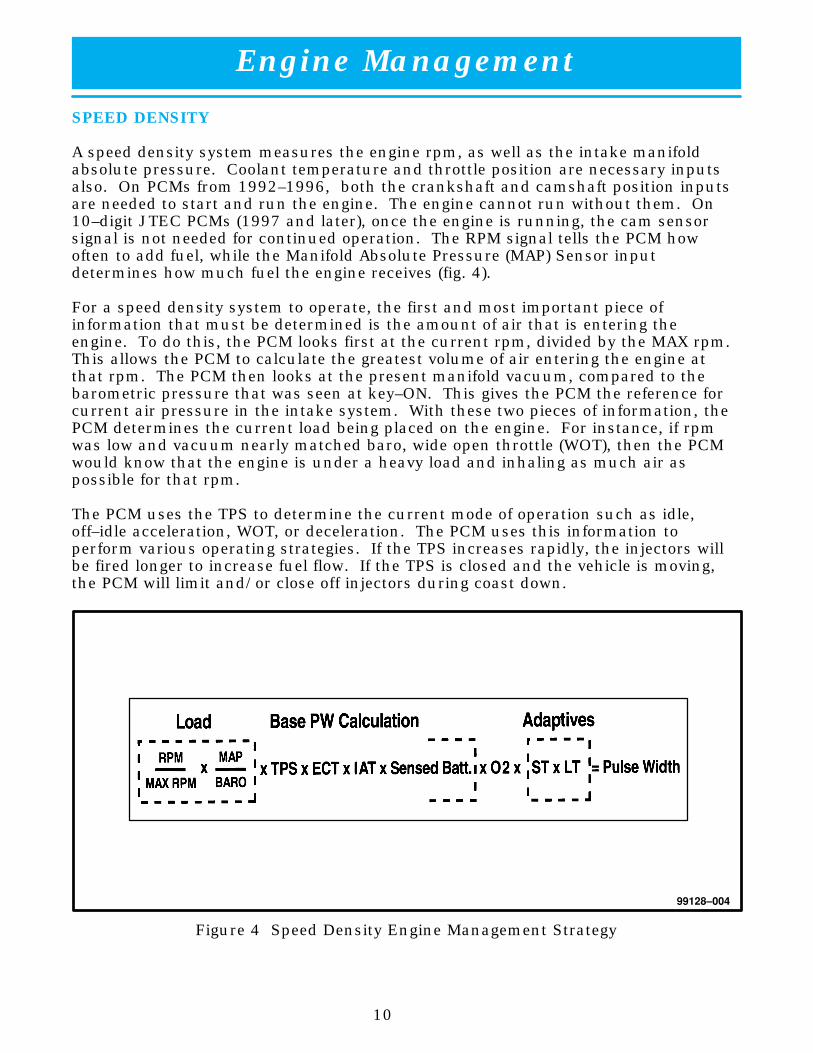
A speed density system measures the engine rpm, as well as the intake manifoldabsolute pressure. Coolant temperature and throttle position are necessary inputsalso. On PCMs from 1992–1996, both the crankshaft and camshaft position inputsare needed to start and run the engine. The engine cannot run without them. On10–digit JTEC PCMs (1997 and later), once the engine is running, the cam sensorsignal is not needed for continued operation. The RPM signal tells the PCM howoften to add fuel, while the Manifold Absolute Pressure (MAP) Sensor inputdetermines how much fuel the engine receives (fig. 4).
For a speed density system to operate, the first and most important piece ofinformation that must be determined is the amount of air that is entering theengine. To do this, the PCM looks first at the current rpm, divided by the MAX rpm.This allows the PCM to calculate the greatest volume of air entering the engine atthat rpm. The PCM then looks at the present manifold vacuum, compared to thebarometric pressure that was seen at key–ON. This gives the PCM the reference forcurrent air pressure in the intake system. With these two pieces of information, thePCM determines the current load being placed on the engine. For instance, if rpmwas low and vacuum nearly matched baro, wide open throttle (WOT), then the PCMwould know that the engine is under a heavy load and inhaling as much air aspossible for that rpm.
The PCM uses the TPS to determine the current mode of operation such as idle,off–idle acceleration, WOT, or deceleration. The PCM uses this information toperform various operating strategies. If the TPS increases rapidly, the injectors willbe fired longer to increase fuel flow. If the TPS is closed and the vehicle is moving,the PCM will limit and/or close off injectors during coast down.
99128–004
Figure 4 Speed Density Engine Management Strategy

Engine Management
11
The PCM has to see a value for every sensor so that it can correctly calculate thepulse. If a sensor goes bad, a value must be substituted. For example, if the MAPSensor is bad, the PCM will use the TPS and rpm to make up a value to use as MAP.
The next modifier is Engine Coolant Temperature (ECT), which is the second biggestmodifier of pulse width, after MAP. If the engine is cold, the fuel will not atomizeeasily. To overcome this problem, the PCM will add extra fuel, depending on thevalue from the ECT. Conversely, if the engine is very hot, fuel will be limited. ECTis also used for engine cooling control. If ECT becomes too high, the PCM willautomatically turn on the cooling fan. If the ECT signal is lost, the PCM willsubstitute a preset (limp–in) value and turn the cooling fan on.
Intake Air Temperature (IAT) is also used to modify the amount of fuel delivered,although it is not as big a modifier as ECT. If ECT is high and IAT shows cold(dense air), then the PCM will add extra fuel. Another feature of IAT is that sparkadvance is limited, if the air is hot (thin). If the IAT signal is lost, the PCM willsubstitute a value based on Battery/Ambient Temperature Sensor.
Sensed battery voltage is needed as a modifier because the injectors are rated forspecific flow at a specific voltage. If the voltage is lower than what the injector wasrated at, it will take longer for the injector to open, and it may not open as far.Therefore, the PCM needs to know the voltage, so it can compensate by changingthe pulse width on–time.
Up to this point, it is not necessary that any fuel is burned, and/or the PCM is in anopen–loop operating condition.
After the fuel is delivered, the PCM looks at the 02 signal to determine how well itdid on the initial calculation. The 02S provides the PCM with the raw input, as tohow much oxygen was left over, after the combustion process.
The adaptive memories allow the PCM to do two things. First, it gives it thecapability to change the pulse width to bring the 02S to its mid–range of operation(short term). Second, it allows to store in memory corrections required for specificoperating conditions (long term).
Based upon all of these inputs, the PCM delivers what it believes to be the optimumpulse width, to deliver the correct emissions performance, fuel economy, anddriveability.

Engine Management
12
FUEL DELIVERY SYSTEM
The fuel system receives fuel pressure from an in–tank pump module. The PCMcontrols the operation of the fuel system by providing battery voltage to the fuelpump through the Fuel Pump Relay. The PCM requires only two inputs and a goodground to operate the Fuel Pump Relay. The two inputs are:
� Ignition voltage
� Crankshaft Position (CKP) Sensor
Note: The PCM uses inputs from the CMP and CKP sensors to calculate engine speed.
EMISSIONS SYSTEM
The emissions system has several components, all used to lower the quantities ofhydrocarbons (HC), carbon monoxide (CO) and oxides of nitrogen (NOx). Emissionssystems are required not only to control the quantity of emissions out the tailpipe,but also any emissions that might be escaping into the atmosphere from the fuelsystem and engine. The emissions system includes:
� Evaporative control system
� Engine crankcase pressure–control system (positive crankcase pressure)
� Exhaust emissions
The PCM controls the evaporative emissions by the operation of a Duty–Cycle Purge(DCP) solenoid. The inputs required to control the DCP solenoid include:
� ECT Sensor
� 02 Sensor
� TPS Engine speed
� MAP Sensor
� Ambient/Battery Temperature Sensor
The engine crankcase is ventilated by a Positive Crankcase Ventilation (PCV) system.It is not controlled by the PCM.
The exhaust emissions are controlled by the use of a catalytic converter, and almostevery input and output of the PCM. The only inputs and outputs that DO NOTcontrol emissions are:
� Tachometer
� Air Conditioning (A/C Request) circuit, A/C Relay, and the A/C PressureSwitches
� ASD and Fuel Pump relays

Engine Management
13
IDLE CONTROL SYSTEMS
The PCM maintains a quality idle by controlling the Idle Air Control (IAC) motor.Inputs to the PCM required to operate the IAC motor include:
� TPS
� MAP Sensor
� ECT Sensor
� VSS
� Spark scatter (output)
� A/C Switch
� Ambient/Battery Temperature sensor
CHARGING CONTROL SYSTEMS
1996 Viper Roadster
The PCM does not control the charging system on the Roadster. Charging systemvoltage control is performed by a regulator built into the generator.
1996 Viper Coupe/1997 All Vipers
The PCM maintains battery voltage within a range of approximately 13.04 volts to15.09 volts by providing battery voltage to the generator field through the ASD Relayand by controlling the ground side of the generator field.
The inputs required to maintain the proper battery voltage are:
� Battery voltage
� BTS
� Engine speed

Engine Management
14
ENGINE COOLING CONTROL SYSTEMS
To maintain engine temperature, the PCM controls the electric Radiator Fan, byproviding battery voltage to the fan through the Radiator Fan ON and High/LowRelays. The PCM controls the ground side of both fan relay coils. The PCM usesthe following inputs to operate the Radiator Fan Relays:
� ECT Sensor
� A/C Switch
� Vehicle speed
A/C CONTROL SYSTEMS
Finally, the PCM uses the A/C Request and Select circuits to identify when toenergize the A/C Relay. The A/C Relay provides the A/C Compressor Clutch withbattery voltage, when energized. Besides the A/C Request and Select circuits, thePCM uses the following inputs to determine when the A/C Relay should beenergized:
� Engine speed
� TPS
� Engine Running Timer
� A/C pressure switches
� ECT Sensor
TRANSMISSION CONTROL
Although the Viper is equipped with a manual transmission, the PCM still has somecontrol functions that it performs. The PCM controls operation of the reverselockout solenoid, first–to–fourth gear shift indicator and the skip shift solenoid.
Note: The following pages of this student reference book describe each section indetail. The function and operation of the inputs and outputs are explained thefirst time each input or output is introduced. Subsequent sections will elaborateon any input or output not previously described.

Engine Management
15
FUEL DELIVERY COMPONENTS
FUEL TANK
From 1992–1997 fuel tanks on Vipers were made of high density polyethylene(HDPE). Starting in 1998, the fuel tank is constructed of extruded 5–layerpolypropylene. From 1992–1995, fuel tank capacity was 22 gallons. In 1996, allmodels switched to a 19–gallon tank. For the 2000 model year, all models switchedto a 18.5–gallon tank. All tanks also incorporate a fuel pump module and rollovervalve (fig. 5). Roadster models have a fuel tank access panel located in the trunkarea, attached with rivets. When servicing the fuel tank on Coupes, an access panelmust be cut in order to remove the tank. If only the fuel pump needs to be serviced,Coupe models have a fuel pump module access panel that can be removed, whilethe Roadster fuel tank must be removed.
In 1998, a leak detection pump (LDP) was added to all Viper models. Starting in2000, all Vipers are equipped with an On–Board Refueling Vapor Recovery (ORVR)system. The LDP and vapor canister move to the rear of the vehicle.
99128–005
ÁÁÁÁÁÁÁÁÁ
1
ÁÁÁÁ
2
Figure 5 Fuel Tank (Typical)
1 Fuel Tank 2 Fuel Pump Module

Engine Management
16
FUEL PUMP MODULE
The Viper fuel pump module is an in–tank unit with an integral fuel level sensor andpressure regulator (fig. 6). The pump is driven by a 12–volt DC motor anytime thefuel pump relay is energized. Serviceable components on the module may be:
� Inlet strainer
� Fuel level sensor
� Filter/pressure regulator
The pump draws fuel through a strainer and pushes it through the motor to theoutlet. The pump contains two check valves. One valve relieves internal fuel pumppressure and regulates maximum pump output. The second valve, in the pumpoutlet, maintains pump pressure during engine–off conditions.
12
4
5
6
7
3
8
99128–006
Figure 6 Fuel Pump Module
1 Full Stop 5 1/4 Tank
2 Full Tank 6 Empty Tank
3 3/4 Tank 7 Empty Stop
4 1/2 Tank 8 Height

Engine Management
17
Check Valve Operation
The electric fuel pump outlet contains a one–way check valve to prevent fuel flowback into the tank and to maintain fuel supply–line pressure (engine warm) whenthe pump is not operational. It is also used to keep the fuel supply line full ofgasoline when the pump is not operating. After the vehicle has cooled down, fuelpressure may drop to 0 psi (cold fluid contracts), but liquid gasoline will remain inthe fuel supply line between the check valve and the fuel injectors. Fuel pressurethat has dropped to 0 psi on a cooled–down vehicle (engine off) is a normalcondition. When the electric fuel pump is activated, fuel pressure shouldimmediately rise to specification.
The fuel systems use a positive displacement, gerotor, immersible pump with apermanent magnet electric motor.
This fuel system does not contain the traditional fuel return lines. The regulatorcontains a calibrated spring, which forces a diaphragm against the fuel filter returnport. When pressure exceeds the calibrated amount, the diaphragm retracts,allowing excess pressure and fuel to vent into the tank.
If the fuel delivery system becomes blocked between the fuel pump and theregulator, the maximum deadhead pressure of the pump is approximately 880 kPa(130 psi). The regulator adjusts fuel system pressure to approximately 379 kPa(55 +/– 5 psi).
A fuel gauge level sending unit is attached to the fuel pump module. The fuel levelinput is used as an input for OBD II. Fuel level below 15% or above 85%, onLDP–equipped vehicles, of total tank capacity disables several monitors. There arediagnostics for the fuel level circuit open and shorted (Table 3).
Table Three Fuel Level Diagnostics
Diagnostic DTC MIL
OBDII Major Monitors Disabled Disabled
Front O2S Voltage Checks Active Active
Rear O2S Voltage Checks Faults Active Active
Front/Rear O2 Heater Active Active
VSS Rationality Active Active
Warning: Be very careful when removing the fuel pump module from the fuel tank asgasoline remaining in the module reservoir will spill.

Engine Management
18
FUEL PRESSURE REGULATOR
All Viper vehicles use a returnless fuel system. On a return system, all fuel isrouted through the hot environment of the engine compartment. Without a returnline, the fuel remains in the tank and is cooler. This reduces evaporative emissions,resulting in less evaporative canister purging.
Returnless fuel systems do not have a return line routed from the fuel rail to thefuel tank. The pressure regulator is part of the fuel pump module. It is part of aregulator assembly on some vehicles and a separate piece on others.
The pressure regulator is a mechanical device that is not controlled by the PCM(fig. 7). The regulator contains a calibrated spring and a diaphragm that actuatesthe regulator valve. Fuel pressure operates on one side of the diaphragm, whilespring pressure operates on the other side. The diaphragm opens the valve to thereturn port, allowing fuel to be dumped back into the fuel tank. System fuelpressure reflects the amount of fuel pressure required to open the port. The springon the opposite side of the diaphragm attempts to close the valve, causing anincrease of pressure on the fuel as it travels to the fuel rail. The spring is notadjustable. The spring is calibrated to maintain approximately 379 kPa (55 +/– 5psi) of fuel pressure.
In the past, the regulator was mounted on the fuel rail so that as the manifoldvacuum at the tip of the injector changed, fuel pressure was modified to maintain aconstant injector flow volume. With the regulator mounted at the tank, a constantfuel pressure is always supplied to the injectors. The PCM uses a special formulausing MAP information that calculates the pressure differential across the injector,and then adjusts injector pulse width.
Fuel Flow
� Remote–mounted filter (two hoses) (1992–1999) – Fuel flows from the pumpto the regulator mounted on top of the module. From the regulator, it flows tothe filter, mounted to the frame, and then to the fuel rail. The regulator on thepump module maintains 55 +/– 5 psi in the filter and lines.
� 2000 – The Viper uses a new filter & regulator which is integral to the pumpmodule. The in–line filter is removed for the 2000 MY.

Engine Management
19
99128–007
ÁÁÁÁ
1
ÁÁÁÁÁÁ
2
ÁÁÁÁÁÁ
3
ÁÁÁÁÁÁ
4
ÁÁÁÁ
5
ÁÁÁÁ
6
ÁÁÁÁ
7
Figure 7 Typical Fuel Pressure Regulator
1 Fuel Flow to Fuel Injectors 5 Fuel Inlet
2 Pressure Regulator 6 Calibrated Springs
3 O–Rings 7 Rubber Grommet at Pump Module
4 Excess Fuel Back to Tank

Engine Management
20
FUEL PUMP RELAY
The Fuel Pump Relay is located in the trunk. It is energized to provide power tooperate the fuel pump under the following conditions:
� For approximately 1.8 seconds during the initial key–on cycle (JTEC).
� For approximately 0.5 to 1.5 seconds during the initial key–on cycle, dependingon temperature (SBEC).
� While the CKP sensor is providing an RPM signal that exceeds a predeterminedvalue.
Ignition voltage is provided to the fuel–pump relay coil anytime the key is in theRUN/START position (figs. 8 & 9). The PCM provides the ground control to energizethe relay. Unlike previous Chrysler systems (non–OBD II), the fuel pump relay doesnot provide power to operate the 02 Sensor heater.
The relay is energized when the key is cycled to RUN to prime the fuel rail withliquid fuel, allowing for a quick start–up. Anytime the CKP sensor indicates that anRPM signal exceeds a predetermined value, the relay is energized to ensure properfuel pressure and volume during engine cranking and running conditions. Anytimethe CKP sensor signal is lost (engine has been shut off or the sensor indicates norpm), the fuel pump relay is de–energized.

Engine Management
21
99128–008
Figure 8 JTEC Fuel Pump Relay Circuit
TO:IGN. COIL02 HEATERASD SENSE
ASDRELAY
99128–009
Figure 9 SBEC Fuel Pump Relay Circuit

Engine Management
22
FUEL INJECTORS
Warning: Release fuel system pressure before servicing fuel system components. Theprocedure is described on the MDS2 and the Service Manual. Service vehiclesand fuel system components in well–ventilated areas. Avoid sparks, flamesand other ignition sources. Never smoke while servicing the vehicle’s fuelsystem.
Caution: If an injector must be removed on a Viper for inspection or service, you mustpurge the fuel rail of all fuel, otherwise, flooding of one cylinder with fuelmay occur. Consult the Fuel Injection section on the MDS2 or theappropriate Service Manual for proper service procedures.
The Viper engine uses bottom feed injectors. They are supplied fuel from a rail thatis part of the intake manifold.
The fuel injectors are 12–ohm electrical solenoids (fig. 10). Each injector contains aneedle valve that closes off an orifice at the nozzle end. When electrical current issupplied to the injector, the armature and needle move a short distance against aspring, allowing fuel to flow out the orifice. Because the fuel is under high pressure,a fine spray is developed in the shape of a hollow cone. The spraying actionatomizes the fuel, adding it to the air entering the combustion chamber.
The fuel injectors are positioned in the intake manifold with the nozzle ends directlyabove the intake valve port for the corresponding cylinder. Fuel is dispersedthrough one opening at the bottom of each injector. This design allows for anatomized spray, similar to that of a pintle injector, but with the low cost and easyserviceability of a pencil–stream injector.
99128–010
ÁÁÁÁ1ÁÁ
ÁÁÁÁ
2
ÁÁÁÁ
3
Figure 10 Fuel Injector
1 Screen (fuel inlet) 3 Upper O–ring
2 Lower O–ring

Engine Management
23
FUEL FILTER
The fuel filter is mounted just outside the tank (fig. 11). The remote filter has twolines attached to it. Filters are life–of–the–vehicle items. Replacement is necessaryonly if something has caused the filter to become plugged, such as contaminants inthe fuel. Regular maintenance is no longer required because only the fuel actuallybeing used by the engine is filtered.
Note: Always lubricate the O–rings inside the quick–connect fittings with engine oil,before reassembling the fuel line connections at the fuel pump module, fuel filterfuel lines and the fuel rail.
99128–011
Figure 11 Fuel Filter

Engine Management
24
FUEL LINES AND RAIL
Fuel Lines
The high–pressure line from the tank to the filter or engine is a combination ofrubber, plastic, and steel lines. The hose clamps used to secure rubber hosesections have a special rolled edge construction to prevent the edge of the clampfrom cutting into the hose.
Note: If the O–rings at the quick–connect fittings become damaged, the line must bereplaced.
Fuel Rail
The fuel rail is an integral part of the intake manifold (fig. 12). The fuel rails attachto the fuel line with a quick connect fitting. If the O–rings at the quick connectfittings become damaged, the line must be replaced. There is a test port located onthe Intake Manifold Right Bank between Injectors #9 and #10. Always follow theprocedures on the MDS2 or the Service Manual when removing fuel systemcomponents.
99128–012
ÁÁÁÁ
1
ÁÁÁÁ
2
ÁÁÁÁ
3
ÁÁÁÁÁÁ
4
Figure 12 Fuel Rails
1 Fuel Rails 3 Fuel Pressure Test Port
2 Intake Manifold 4 Fuel Injection

Engine Management
25
NOTES:

Engine Management
26
THROTTLE BODY
The throttle bodies are mounted to the intake manifold. On Vipers equipped withthe heavyweight engine, a separate throttle cable and linkage control each throttlebody (fig. 13). The throttle cables must be adjusted after replacement or removal ofone or both throttle bodies, or after installation of a new throttle cable. The throttlecable will require adjustment if the throttle arm does not contact the throttle stopon the throttle body housing at WOT. For throttle cable adjustment procedures,refer to the MDS2 or the Service Manual.
Vipers equipped with the lightweight engine incorporate a single throttle cabledesign with a synchronization shaft (fig. 14). The throttle cable controls the leftthrottle plate and mechanical motion is transmitted to the opposite throttle platethrough a synchronization shaft. This shaft is not an adjustable component. It iscalibrated at the factory and is serviced as a replacement component only.
The contoured throttle body changes air velocity slightly with moderate pedalmovement. The first 1/3 of opening takes a lot of throttle movement, then openingoccurs much faster. This helps reduce buck and bobble at light throttle positions.The TPS is attached to the left throttle body.
ÁÁÁÁ
99128–013
ÁÁÁÁÁÁ
1
ÁÁÁÁ
2
ÁÁÁÁ
3
ÁÁÁÁÁÁ
4
Figure 13 Heavyweight Throttle Attachments
1 Shaft 3 Button
2 Clasp 4 Ratchet

Engine Management
27
99128–014
Figure 14 Lightweight Throttle Synchronization Shaft

Engine Management
28
POWERTRAIN CONTROL MODULE
POWER SUPPLIES AND GROUNDS (JTEC)
In order to function, the PCM must be supplied with battery voltage and a ground(fig. 15). The PCM monitors battery voltage during engine operation. If the voltagelevel falls, the PCM increases the initial injector opening point to compensate for lowvoltage at the injector. Low voltage causes a decrease in current flow through theinjector and can prevent the injector plunger from fully opening in the allotted time,resulting in decreased fuel flow.
Battery charging rate is controlled by the PCM, except on 1996 Roadsters. Thetarget charging rate voltage is based upon inputs from Battery Temperature Sensor(BTS). The BTS is located in the bottom of the battery tray.
The PCM must be able to store diagnostic information. This information is stored ina battery–backed RAM. Once a Diagnostic Trouble Code (DTC) is read, thetechnician can clear the RAM by disconnecting the battery for approximately 60seconds, or using the DRBIII scan tool.
The PCM has two power inputs: direct 12 volts and switched ignition 12 volts.Battery voltage is supplied to the PCM to power the 5–volt power supply and allowthe PCM to perform fuel, ignition and emission control functions. The PCMmonitors this direct battery–feed input to determine charging rate, control theinjector initial opening point, and back up the RAM used to store the DTC functions.This is called sensed battery and will be discussed later.
When the ignition switch is turned ON, the 12–volt input acts as a “wake up” signalto an integrated circuit that then turns on the power supply.
The power supply output of 5 volts supplies multiple locations within the controllerand is also used as the reference voltage for sensor operation. Some of the locationswithin the controller that use 5 volts are the microprocessors. Another output ofthe 5–volt power supply is a line that is split to make the primary and secondary5–volt outputs.
The primary output is used as a reference voltage for the TPS and MAP sensors aswell as a power supply to operate the CMP and CKP sensors. It is also used as apower supply for the VSS.

Engine Management
29
Another use of the power supply is a reference voltage for the internal use of thePCM. The microprocessors determine current sensor state by comparing the sensorsignal to the reference voltage. The difference between the two voltages equals thesensor state.
The PCM has two grounds, both identified as power grounds. All the high current,noisy devices are connected to these grounds as well as all the sensor returns. Thesensor return comes in, passes through noise suppression and is then connected tothe power ground.
99128–015
Figure 15 JTEC Power Supplies and Grounds

Engine Management
30
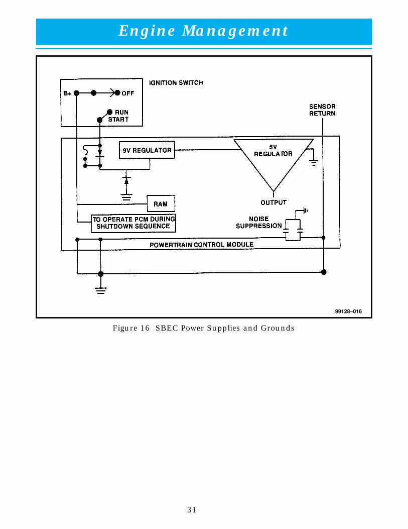
POWER SUPPLIES AND GROUNDS (SBEC)
In order to function, the PCM must be supplied with battery voltage and a ground(fig. 16). The PCM monitors battery voltage during engine operation. If the voltagelevel falls, the PCM increases the initial injector opening point to compensate for lowvoltage at the injector. Low voltage causes a decrease in current flow through theinjector and can prevent the injector plunger from fully opening in the allotted time,resulting in decreased fuel flow.
The PCM must be able to store diagnostic information. This information is stored ina battery–backed RAM. Once a DTC is read by the technician, the technician canclear the RAM by disconnecting the battery for approximately 60 seconds, or usingthe DRBIII scan tool.
The PCM monitors the direct battery feed input to control the injector initial openingpoint and back–up the RAM used to store DTCs. Direct battery feed is also used tosupply working voltage to the controller. This is called sensed battery and will bediscussed later.
Ignition voltage is supplied to the PCM. Battery voltage is supplied to this pinthrough the Ignition Switch when the ignition key is in the RUN or START position.Voltage is supplied to this circuit to power the 9–volt regulator and to allow the PCMto perform fuel, ignition, and emissions control functions. This ignition input actsas a “wake up” signal to the PCM. The battery voltage on this line is supplied to the9–volt regulator which then passes on a power supply to the 5–volt regulator.Voltage on the ignition input can be as low as 6 volts and the PCM will still function.
Internally, all ground pins are connected together, however there is a noisesuppression on the sensor ground. For Electro Magnetic Interface (EMI) and RadioFrequency Interface (RFI) protection, the case is also grounded separately from theground pins.
A 9–volt power supply is provided to supply the VSS, CKP, and CMP sensors with aregulated voltage. The same power supply also provides the 5–volt regulator withpower. The 9–volt regulator is protected from short circuits. If the regulator wereexternally shorted to ground, a circuit in the regulator would cause the externalsupply voltage to shut down, but still provide power to the 5–volt regulator.
A 5–volt power supply is used to provide a regulated power supply to most of theinputs to the PCM. This circuit is also protected from shorts to ground and a circuitin the regulator allows the 5–volt signal to be sent to other inputs if the 5–volt powersupply were shorted to ground at the MAP sensor or TPS.
Engine Management
31
99128–016
Figure 16 SBEC Power Supplies and Grounds

Engine Management
32
DATA LINK CONNECTOR (DLC)
The PCM maintains communication with scan tools through the vehicle’s DLC. TheDLC for pre–1996 Vipers is located under the hood, next to the PCM. From 1996forward, the DLC is located inside the vehicle, below the Instrument Panel and tothe left of the clutch pedal (fig. 17). This change in location is a result of OBD II.
99128–017
ÁÁÁÁ
1
ÁÁÁÁ
2
ÁÁÁÁÁÁ
3
Figure 17 Data Link Connector (1996 and Later)
1 Brake Pedal 3 Data Link Connector
2 Clutch Pedal

Engine Management
33
NOTES:

Engine Management
34
FUEL INJECTION SYSTEM — PCM INPUTS
CRANKSHAFT POSITION SENSOR (CKP)
The Crankshaft Position Sensor (CKP) is mounted in the passenger side of theengine block, below the exhaust manifold. The CKP is a Hall–effect type sensor thatis used to provide input to the PCM regarding the exact position of the crankshaftand pistons. This type of sensor detects slots cut into a pulse ring machined intothe middle of the crankshaft. The CKP signal alone is used to determine engineRPM. When combined with input from the Camshaft Position Sensor (CMP –discussed later), CKP input is used to determine:
� Top Dead Center (TDC)
� Ignition Timing
� Injector Synchronization
Note: The engine will not start if the PCM does not receive the CKP signal.
The pulse ring has five groups of two notches equally spaced at its outer edge(fig. 18). Each group of notches represents a signal for a specific set of pistons. ThePCM determines basic timing by the position of the falling edge of the slots. Eachcorresponding slot is 72° apart and is 3° wide. There are 15° between each slot inthe pair. The falling edge of the first slot of each pair of slots is used for cylinders10, 4, 6,8 and 2, and the second falling edge is used for cylinders 1, 9, 3, 5 and 7(fig. 19). It may take the PCM one full engine revolution to determine crankshaftposition while cranking. The following shows companion or paired cylinders:
� #10 and #5
� #9 and #8
� #4 and #7
� #3 and #2
� #1 and #6
The V10 is a 90° block. This means that the combined angle of the bore center linesof the opposing banks are 90° and that a piston comes up to TDC every 90°. With10 cylinders, each one would be fired in 900° of crankshaft rotation (10 x 90 =900).To match cylinder firing with crankshaft rotation, it was necessary to make an “oddfire” engine. This means that all the cylinders are not fired at the same amount ofcrankshaft rotation. Five cylinders are fired at 54° and the other five are fired at 90°of crankshaft rotation (fig. 19). All of these angles added together total 720° or twocomplete crankshaft revolutions. Because of the odd firing, it is necessary to usedifferent notch edges to properly stagger the spark.
Note: The CKP does not inform the SBEC which pistons are approaching top deadcenter (TDC). The CMP signal provides this information.

Engine Management
35
99128–018
Figure 18 Crankshaft Notches

Engine Management
36
99128–019
Figure 19 Crankshaft Pulse Ring

Engine Management
37
The PCM supplies 5 volts (9 volts on SBEC) to the sensor for operation of theHall–effect chip and other sensor electronics (figs. 20 & 21). The PCM also providesa ground for the sensor on the sensor return circuit. Finally, the PCM provides a5–volt reference signal to the CKP through a third circuit. This reference voltagealternates between 5 volts and 0 volts with the rotation of the crankshaft.
The Hall–effect switch contains a magnet. As the magnetic field passes over thesolid portion of the pulse ring, the 5–volt signal is pulled to ground through atransistor in the sensor. When a notch is in front of the sensor, the transistor isturned off and the reference voltage rises to 5 volts. The PCM identifies crankshaftposition by registering the cycles from 0 to 5 volts.
99128–020
Figure 20 JTEC Crankshaft Position Sensor Circuit

Engine Management
38
ÁÁÁÁÁÁÁÁ
ÁÁÁÁÁÁCMP
ÁÁÁÁÁÁÁÁ
VSS
ÁÁÁÁÁÁÁÁÁÁÁÁ
VIC
99128–021
Figure 21 SBEC Crankshaft Position Sensor Circuit

Engine Management
39
Crankshaft Position Sensor Service
The sensor’s powerful magnet is susceptible to damage. Do not drop the sensor ona metal table, or store sensors face–to–face. The clearance between the sensor andthe counterweight is not adjustable. Though the clearance is critical,manufacturing tolerances allow for some differences in clearance.
In order for the vehicle to start, both the cam and crankshaft position sensor signalsmust be present. On SBEC PCMs and eight–digit part number JTEC PCMs, boththe cam and crankshaft position sensor signals are necessary for continuedoperation.
On 10–digit part number PCMs (1997 and later), once the engine is running, thecam sensor signal is not needed for continued operation.
Caution: The crankshaft position sensor has a foil heat shield attached by the CKPmounting bolt covering the sensor. The heat shield must be propertyinstalled to ensure that the CKP sensor remains protected from the heat ofthe exhaust system.

Engine Management
40
CAMSHAFT POSITION SENSOR (CMP) (JTEC)
The Camshaft Position Sensor (CMP) functions similarly to the CKP. The CMP isalso a Hall–effect sensor that provides input to the PCM regarding crankshaftposition and cylinder identification. The PCM uses the CMP input along with theCKP input to determine exact piston location and determines spark/fuel delivery.
The CMP Sensor is mounted in the front of the timing case cover (fig. 22). Thecamshaft sprocket has a metallic step that passes in front of the CMP sensor. ThePCM is able to identify piston location by monitoring the position of this step.
99128–022
ÁÁÁÁÁÁÁÁÁ
1
ÁÁÁÁÁÁ
2
ÁÁÁÁÁÁÁÁÁ
3
ÁÁÁÁ
4
Figure 22 JTEC Camshaft Position Sensor Operation
1 Timing Step 3 Mounting Bolt
2 Camshaft Sprocket 4 Camshaft Position Sensor
Engine Management
41
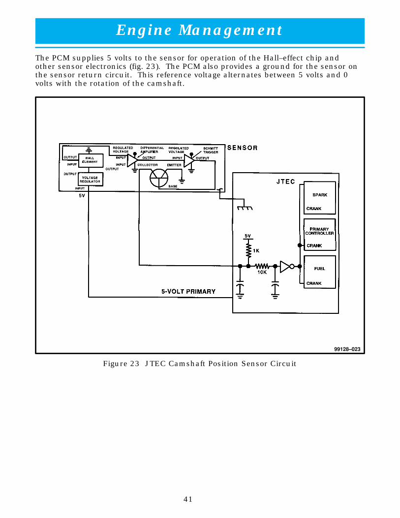
The PCM supplies 5 volts to the sensor for operation of the Hall–effect chip andother sensor electronics (fig. 23). The PCM also provides a ground for the sensor onthe sensor return circuit. This reference voltage alternates between 5 volts and 0volts with the rotation of the camshaft.
99128–023
Figure 23 JTEC Camshaft Position Sensor Circuit

Engine Management
42
Similar to the CKP, when the step passes in front of the CMP, the 5 volt referencevoltage from the PCM goes to approximately 0 volts. When the step rotates awayfrom the sensor, the reference voltage returns to 5 volts. The result is a squarewave signal that alternates between 0 and 5 volts (fig. 24).
99128–024
ÁÁÁÁÁÁ
1
ÁÁÁÁ
2
Figure 24 JTEC CMP Sensor Signal
1 Crankshaft 2 Camshaft

Engine Management
43
The PCM determines crankshaft position from the inputs provided by the Camshaftand Crankshaft Position Sensors. Once the crankshaft position is determined thePCM can synchronize fuel injection and cylinder identification.
In order for the vehicle to start, both the CMP and CKP sensor signals must bepresent. On 1992–1996 vehicles, both CMP and CKP sensor signals are necessaryfor continued engine operation. On 1997 and later vehicles, once the engine isrunning, the CMP sensor signal is not needed for continued engine operation.
When the PCM sees the falling edge of the CMP sensor it knows that cylinder #1 isnext. When the PCM sees the second falling edge after the CMP sensor it knowsthat the crankshaft is at 9° BTDC compression for cylinder #1. The PCM thenknows that the next falling edge it will see is 9° BTDC compression for cylinder #10and so on. Because of the odd fire the injector–firing is also staggered. Theinjectors for cylinders 1, 9, 3, 5 and 7 are fired at 423° BTDC. The injectors forcylinders 10, 4, 6, 8 and 2 are fired at 441° BTDC.
Cam/Crank Diagnosis
In order for the PCM to diagnose either the CAM or CRANK sensor signals, one ofthe signals must be present.
Camshaft Position Sensor Service
Caution: When installing a CMP sensor the cam drive gear position must be checked.If the cam gear is positioned at the low area, the sensor will be brokenwhen the engine is started. Refer to the MDS2 or the Service Manual forproper procedures.

Engine Management
44
CAMSHAFT POSITION SENSOR (CMP) (SBEC)
The PCM sends approximately 9 volts to the Hall–effect sensor (fig. 25). This voltageis required to operate the Hall–effect chip and the electronics inside the sensor. Aground for the sensor is provided through the sensor return circuit. The input tothe PCM occurs on a 5–volt output reference circuit. The PCM identifies camshaftposition by registering the change from 5 to 0 volts, as signaled from the CMP.
99128–025
ÁÁÁÁÁÁÁÁÁÁÁÁ
ÁÁÁÁÁÁÁÁÁÁÁÁÁÁÁÁ
ÁÁÁÁÁÁÁÁ
VIC
ÁÁÁÁÁÁÁÁ
CKPÁÁÁÁÁÁ
VSS
Figure 25 SBEC Camshaft Position Sensor Circuit

Engine Management
45
The camshaft timing gear has six areas with notched slots (fig. 26). There are twoareas with a single slot spaced 180° apart and one area with two slots spaced nextto each other. The timing gear also has one long and two shorter, solid, un–notchedsurfaces. Because of the arrangement of solid and notched areas on the camshafttiming gear, a predictable sequence of signals is produced, which allows the SBECto determine camshaft position. The SBEC then calculates which coil and injectorshould be energized. The SBEC is able to make these calculations within onerevolution of start–up.
99128–026
Figure 26 SBEC Camshaft Sprocket

Engine Management
46
The PCM determines fuel injection synchronization and cylinder identification frominputs provided by the CMP and CKP (fig. 27). From the two inputs, the PCMdetermines camshaft–to–crankshaft misalignment.
99128–027
ÁÁÁÁÁÁÁÁÁ
1
ÁÁÁÁ
2
ÁÁÁÁÁÁ
3
Figure 27 SBEC Camshaft Position Sensor Signal
1 Synchronization 3 Camshaft
2 Crankshaft

Engine Management
47
NOTES:

Engine Management
48
Injection/Ignition Timing
The term “sequential” means the injectors have a specific firing order, and fuelinjection is timed to piston movement. Although it is a fuel system, sequentialinjection is more easily understood if it is compared to an ignition system. Ignitiontiming matches spark plug firing to piston position, and spark plugs are fired in aspecific order: 1–10–9–4–3–6–5–8–7–2.
In order for the SBEC to fire injectors in a specific order timed to crankshaft andpiston movement, it must first establish a reference point. Establishing thereference point requires SBEC inputs from the CKP and CMP. The CKP provides theSBEC with crankshaft angle and speed. The SBEC converts crankshaft speed intoengine rpm and crankshaft angle into piston position. The notched crankshaft,rotating past the CKP, contains 5 pairs of two notches, equally spaced around thecrankshaft. Each notch represents a signal for piston position. The CMP receivessignals from the notches on the camshaft timing gear. The timing gear has an areaof two single notches spaced 180° apart and an area with two notches next to eachother. The timing gear also has one long and two shorter, solid, un–notchedsurfaces. These signals provide information as to which piston is approaching TDC.Based on these inputs, the SBEC energizes the appropriate injector for a particularcylinder, and energizes the ignition coil to fire the spark plugs of those pairedcylinders.
When the engine is running, based on its sync signal, it energizes the injector 432°of crankshaft rotation prior to ignition. For example: when the VIC recognizescylinder #1, it energizes the injector for cylinder #5. The ignition coil dwell can bestarted any time before TDC of the previous cylinder in the firing order. However,during high rpms, the dwell time can be as many as four previous cylinders in thefiring order.

Engine Management
49
Sychronization
There are only three ways the engine can “sync”; otherwise, the engine will not start.The three conditions are (fig. 28):
� If the SBEC sees seven crank signals (with no sync) after one camshaft signal has been encountered.
� If the SBEC receives seven (+) crankshaft signals, and then a signal from the CMP.
� If the SBEC receives two camshaft signals encountered between two crankshaft signals.
Since the SBEC does not have enough output drivers to support all of the injectors,two of the injectors, #1 and #5, are controlled by the VIC.
99128–028
ÁÁÁÁÁÁÁÁÁ
1
ÁÁÁÁ
2
ÁÁÁÁÁÁ
3
Figure 28 Synchronization
1 Synchronization 3 Camshaft
2 Crankshaft

Engine Management
50
MANIFOLD ABSOLUTE PRESSURE (MAP) SENSOR
The MAP signal serves as a PCM input, using a silicon–based sensing unit to providedata on the manifold vacuum that draws the air/fuel mixture into the combustionchamber. The PCM requires this information to determine injector pulse width andspark advance. When MAP voltage (engine running) equals the voltage seen whenbarometric pressure was learned or updated, the pulse width will be at itsmaximum.
Also, like the cam and crank sensors, 5 volts is supplied from the PCM and the MAPSensor returns a voltage signal to the PCM that reflects manifold pressure (figs. 29& 30). The MAP Sensor operating range is from 0.45 volt (high vacuum) to 4.8 volts(low vacuum). The sensor is supplied a regulated 4.8 to 5.1 volts to operate thesensor. Like the cam and crank sensors, ground is provided through the sensorreturn circuit.
99128–029
Figure 29 JTEC Manifold Absolute Pressure Sensor Circuit

Engine Management
51
99128–030
PCM
MAP
5V SENSOR
5V SENSOR
5V SUPPLY
SENSORRETURN
A/D CONV.
SENSOR
A/D CONV.
SENSOR
5VPOS.
TPS
TO VSS
Figure 30 SBEC Manifold Absolute Pressure Sensor Circuit

Engine Management
52
The MAP Sensor input is the number one contributor to pulse width. An importantfunction of the MAP Sensor is to determine barometric pressure (fig. 31). The PCMneeds to know if the vehicle is at sea level, or in Denver at 5,000 feet above sea level,because the air density changes with altitude. It will also help to correct for varyingweather conditions. This is important, because as air pressure changes, barometricpressure changes. Barometric pressure and altitude have a direct inversecorrelation; as altitude goes up, barometric pressure goes down. The first thing thathappens as the key is rolled on, before reaching the crank position, the PCM powersup, looks at the MAP voltage, and based upon the voltage it sees, it knows thecurrent barometric pressure relative to altitude.
99128–031
ÁÁÁÁÁÁ
1
ÁÁÁÁÁÁ
2
��������
��
Figure 31 MAP Sensor Voltage Values
1 Altitude in Thousands 2 Voltage

Engine Management
53
Once the engine starts, the PCM looks at the voltage again at the trailing edge of thelast slot on the current cylinder and the leading edge of the first slot of the nextcylinder. These two values are added and then divided by 2 to get an average. Itthen averages these signals and compares the current voltage to what it was atkey–ON. The difference between current voltage and what voltage was at key ON ismanifold vacuum (fig. 32).
99128–032
ÁÁÁÁ
1
ÁÁÁÁ
2
ÁÁÁÁÁÁ
3
Figure 32 MAP Voltage vs. Vacuum
1 Done at 29.92 Baro at Sea Level 3 Vacuum
2 Voltage

Engine Management
54
During key–ON (engine not running) the sensor reads (updates) barometric (Baro)pressure. A normal range can be obtained by monitoring a known valid sensor.
As the altitude increases, the air becomes thinner (less oxygen). If a vehicle isstarted and driven to a very different altitude than where it was at key ON, thebarometric pressure must be updated. Anytime the PCM sees at least 1.8 voltsabove minimum TPS, and based upon rpm, it will update barometric pressure in theMAP memory cell. With periodic updates, the PCM can make its calculations moreeffectively. Also, if MAP is ever greater than Baro, such as coming down from a highaltitude, Baro automatically updates.
The PCM uses the MAP Sensor to aid in calculating the following:
� Barometric pressure.
� Engine load.
� Manifold pressure.
� Injector pulse width.
� Spark–advance programs.
� IAC position.
� Deceleration fuel shutoff.
The PCM recognizes a decrease in manifold pressure by monitoring a decrease involtage from the reading stored in the barometric pressure memory cell. The MAPSensor is a linear sensor. As pressure changes, voltage changes proportionately.The range of voltage output from the sensor is usually between 4.6 volts at sea levelto as low as 0.3 volt at 26 in. Hg. of manifold vacuum. Barometric pressure is thepressure exerted by the atmosphere upon an object. At sea level, on a standardday, with no storm, barometric pressure is 29.92 in. Hg. For every 100 feet ofaltitude, barometric pressure drops 0.10 in. Hg. A storm can either add (highpressure) or decrease (low pressure) from what should be present for that altitude.You should know the average pressure and corresponding barometric pressure foryour area. Always use the Diagnostic Test Procedures Manual for MAP Sensortesting.
The MAP Sensor signal is provided from a single silicone piezoresistive elementlocated in the center of a diaphragm. The element and diaphragm are both made ofsilicone. Pressure change moves the diaphragm, causing the element to deflect,which in turn stresses the silicone. When silicone is exposed to stress, itsresistance changes. As manifold vacuum increases, the MAP Sensor input voltagedecreases proportionally. The sensor also contains electronics that filters the signaland provides temperature compensation.
Engine Management
55
MAP Sensor Diagnostics
Note: JTEC examples are given, SBEC are similar. Refer to the applicable PowertrainDiagnostic Manual or MDS2 for the vehicle you are servicing.
There are three MAP Sensor diagnostic routines:
� MAP voltage too high (voltage is above 4.9 volts).
� MAP voltage too low (voltage below 2.35 volts at start–up or below 0.1 volt withengine running).
� No change in MAP voltage at start–to–run transfer.
With the engine running between 400 to 1,500 rpm, near closed throttle and MAPvoltage is above 4.9 volts, the voltage high fault is set. Beginning with the 1997model year, the MAP diagnostic range is 416 to 3,500 rpm.
There are two different ways to set the voltage low fault. If MAP voltage is below2.35 volts at start–up, the fault will be set. The other is MAP voltage below O. 1 voltwhile the engine is running.
To set the rationality fault “no change in MAP from start to run”, the PCM mustdetect too small a difference between engine MAP voltage running and Baro atkey–ON. This is checked at all times. If rpm becomes close to idle speed and thethrottle is closed, vacuum should be greater than a calibrated amount. If vacuum isnot high, then a fault will be set.
MAP voltage is only looked at when the vehicle is near closed throttle and rpm isbetween approximately 400 to 1,500 rpm. This means that if a MAP sensor is faultyat an rpm above 1,500, the PCM will interpret whatever reading it gets from theMAP sensor as true. Beginning with the 1997 model year, the MAP diagnostic rangeis 416 to 3,500 rpm.
MAP Sensor Limp–In
The PCM stores a DTC when the MAP sensor malfunctions. When the PCM sets aDTC, the MAP sensor’s information is considered inaccurate. At this point, the PCMmoves into “limp–in” mode. Limp–in for the MAP sensor allows the engine tocontinue to function, without input to the PCM from the MAP. The PCM mustcalculate the amount of air being consumed by the engine, which is accomplishedby calculating MAP values based upon readings from the CKP sensor (RPM) and theThrottle Position Sensor (TPS). Anytime the PCM sets a DTC for MAP, theMalfunction Indicator Light (MIL) is illuminated.

Engine Management
56
Component Locations
The MAP Sensor is located on the rear portion of the left intake manifold (fig. 33).
99128–033
ÁÁÁÁÁÁ
1
ÁÁÁÁÁÁÁÁÁ
2
Figure 33 MAP Sensor Location
1 MAP Sensor 2 Intake Manifold

Engine Management
57
THROTTLE POSITION SENSOR (TPS)
The TPS is mounted to the side of the throttle body. The PCM needs to identify theactions of the throttle blade at all times to assist in performing the followingcalculations:
� Ignition timing advance.
� Fuel injection pulse–width.
� Idle (learned value or minimum TPS).
� Off–Idle (0.04 volt above minimum TPS) (0.06 volt for SBEC).
� Wide–Open Throttle (WOT) open loop (2.608 volts above learned idle voltage).
� Deceleration fuel lean–out.
� Fuel cutoff during cranking at WOT (2.608 volts above learned idle voltage).
The PCM supplies the TPS with a regulated voltage that ranges from 4.8 to 5. 1 volts(figs. 34 & 35). On SBEC, the regulated output voltage is the same voltage that theMAP Sensor uses. On JTEC, the 5–volt reference (primary) is the same voltage thatthe MAP, CMP, and CKP Sensors use. The TPS receives its ground from the PCM.The input of the TPS to the PCM is through a 5–volt sensor circuit.

Engine Management
58
99128–034
Figure 34 JTEC Throttle Position Sensor Circuit

Engine Management
59
TO MAP SENSOR
THROTTLEPOSITIONSENSOR
99128–035
Figure 35 SBEC Throttle Position Sensor

Engine Management
60
TPS PROGRAMS
Idle
As with other Chrysler fuel–injection systems, the PCM is able to recognize an idlecommand based upon inputs from the TPS. Also, like other Chrysler systems, thePCM is programmed to monitor the TPS signal whenever the key is ON. While thekey is ON and the engine is running, the PCM assumes that the lowest voltage itcan receive, above the fault threshold, must be where the throttle blade lever hitsthe idle stop. Normally, this voltage range is approximately 0.5–1.0 volt. At thelow–voltage position, the PCM records the signal as “idle,” better known as“minimum TPS.”
The PCM’s memory is updated anytime the sensed voltage is less than the recordedvalue in the memory cell. The PCM uses voltage change to determine when thethrottle has returned to the previously learned value. At key ON, the PCM will raisethe target voltage value in the TPS Min idle memory cell by approximately 0.04 of avolt. This new value becomes the new minimum TPS. When the engine is started, ifthe actual TPS voltage is lower than the new memory value, the PCM will storeactual as minimum TPS.
Note: JTEC examples given; SBEC similar.
If the key is cycled ON without starting the engine (start–to–run transfer), the valuein target memory will increase up to a maximum of approximately 1.0 volt. Oncethe maximum is reached, the voltage will automatically drop to approximately 0.86volt. At the next key–on it will increment 0.04 volt and will stay in this loop until itcan learn a new actual minimum with the engine running. Limiting the upperthreshold of minimum TPS reduces the chance that minimum TPS would get sohigh that the clear flood function would not work.
Anytime the PCM receives the idle voltage signal, the PCM is programmed tomaintain target idle, using timing and the Idle Air Control (IAC) motor. Idle speedmay vary, based on ECT.
Spark advance curves and injection pulse–width programs are unique as they arespecifically calibrated for idle conditions.
Off–Idle
Once the throttle is opened, the PCM moves into its off–idle program atapproximately 0.04 volt above minimum TPS. At this point, spark scatter advanceis no longer being used to control idle speed. The IAC motor has been repositionedto act like a dashpot. The dashpot function operates the IAC motor, to prevent thepossibility of the engine dying out during a sudden deceleration. So, if the throttleblade is actually closed but the TPS voltage did not drop to minimum TPS (dirtythrottle body), idle quality will be poor: minimum TPS with engine running cannotbe learned upward (higher voltage than minimum TPS to .04). Only a lower voltagecan be learned.

Engine Management
61
Acceleration
A rapid rise in TPS voltage within a specified time frame causes the injector pulsewidth to increase. The amount of pulse width increase is determined by the rate ofvoltage rise. For maximum response, the PCM will momentarily increase the pulsewidth for all the injectors.
Wide Open Throttle (WOT)
With the engine running, the PCM spark–advance and fuel pulse–width programsare affected during WOT conditions. The PCM is programmed to go into open loopanytime the TPS voltage exceeds 2.7 volts (80% throttle blade) above minimum idle.This enables the PCM to enrich the air/fuel ratio at WOT to allow the combustionchamber to run a little cooler.
Deceleration
Under deceleration, the PCM is programmed to “lean out” the air/fuel ratio, sinceengine power is not needed. One of the main components involved with thedeceleration program is the TPS. If, while the vehicle is in motion (based on theVehicle Speed Sensor), the TPS is closed, and manifold vacuum is high, the PCMnarrows the pulse width, so that the air/fuel ratio becomes leaner. In someinstances, the pulse width goes to 0.0 msec., at which time no fuel is supplied to theengine. This action causes extremely low vehicle emissions. During deceleration,the adaptive numerator is updated, as there is no load on the crankshaft. Theadaptive numerator is explained in detail in the On Board Diagnostics II StudentWorkbook.
Wide Open Throttle Fuel Cut–Off During Cranking
One last function that the PCM performs from inputs delivered by the TPS is theWOT fuel cut–off while cranking. To ensure short cranking times, the PCM fires allof the injectors simultaneously once during cranking. After that, the PCM waits tworevolutions, then fires the injectors sequentially. If the programmed pulse widthallows too much fuel into the combustion chamber, or if circumstances do not allowthe engine to start up with the programmed quantity of fuel, the driver can operatethe accelerator pedal to WOT, so the PCM de–energizes all injectors. This programoccurs only during cranking, and when the TPS voltage exceeds 2.4 volts aboveminimum TPS.

Engine Management
62
TPS Diagnostics
Note: JTEC examples given, SBEC similar.
There are three TPS diagnostic routines:
� TPS voltage high (above 4.9 volts)
� TPS voltage low (below 0.1 volts)
� TPS voltage does not agree with MAP
The diagnostic routine “TPS voltage low” is set when TPS voltage is below 0.1 voltand engine speed is greater than 1500 rpm. The “TPS voltage high” routine is setwhen TPS voltage is above 4.9 volts and engine rpm is as follows: above 1500 rpmfor 1996, or between 416–3500 rpm for 1997. The diagnostic routine: “TPS voltagedoes not agree with MAP” fault is set when the PCM interprets the MAP indicationas a load condition that does not agree with what the TPS indicates. This can occurin two ways: TPS voltage less than 1.16 volts with vacuum less than 2 in., or TPSvoltage more than 2.16 volts and vacuum greater than 11.8 in.
TPS Limp–In
When the TPS indicates a voltage that is too low, too high or not believable, the PCMsets a DTC. When the DTC is set, the MIL is illuminated and the PCM moves intolimp–in mode. Limp–in for the TPS is divided into three categories: idle, part–throttle and WOT. These limp–in values are mainly rpm–based, although the MAPsensor has an input to the program. Refer to the Diagnostic Test ProceduresManual for complete diagnostic information.

Engine Management
63
NOTES:

Engine Management
64
ENGINE COOLANT TEMPERATURE (ECT) SENSOR
On lightweight engines, the ECT is located on the front of the driver side cylinderhead, just beneath the left throttle body (fig. 36). On heavyweight engines, the ECTis located below the rear of the intake manifold near the thermostat housing (fig.37).
99128–036
ÁÁÁÁ
1
ÁÁÁÁÁÁ
2
Figure 36 Lightweight ECT Location
1 ECT Sensor 2 Thermostat Housing

Engine Management
65
99128–037
ÁÁÁÁ
1
ÁÁÁÁÁÁ
2ÁÁÁÁÁÁ
3
Figure 37 Heavyweight ECT Location
1 Rear of Engine 3 Temperature Gauge Sensor
2 ECT Sensor
The PCM uses inputs from the ECT sensor to calculate:� Injector pulse width� Spark–advance curves� Fuel Pump Relay Latch Times (SBEC only)� Idle Air Control (IAC) motor key–on steps� Initial fuel injection� O2 Sensor closed–loop times (30° and above)� Purge solenoid on/off times� Radiator fan relay on/off points� Target idle speed
The ECT input is the second most powerful modifier of injector pulse width. TheECT Sensor is a Negative Thermal Coefficient (NTC) sensor. The PCM sends fivevolts to the sensor, and is grounded through the sensor return line (fig. 38). Astemperature increases, resistance in the sensor decreases (fig. 39).
As the temperature goes up, the voltage drop increases, which causes a lowervoltage at the A/D converter. Unlike SBEC, the JTEC ECT is not a dual–rangingcircuit.
1996 Coupe/1997–2000 All
The ECT Sensor on these vehicles is a 4 wire sensor located in the front of the driverside cylinder head. Two wires are for the gauge and two for the sensor input to thePCM. This sensor is used as a PCM input, a message center input for thedashboard warning light, and for the water temperature gauge.

Engine Management
66
99128–038
JTEC
SBEC
MessageCenter
Engine CoolantTemperatureSensor
CaseGround
Engine CoolantTemperatureGauge
Figure 38 Engine Coolant Temperature Sensor Circuits (SBEC and JTEC)

Engine Management
67
99128–039
Resistance
Temperature (Degrees F)
Figure 39 ECT/IAT Temperature/Resistance Curve (SBEC & JTEC)

Engine Management
68
ECT Operation
As the temperature of the coolant goes up, the voltage drop increases, which causesa lower voltage at the A/D converter (fig. 40). Unlike previous years (SBEC), this isnot a dual–range circuit.
99128–040
Figure 40 JTEC ECT/IAT Temperature/Voltage Curve

Engine Management
69
The SBEC PCM has a dual temperature–range program for better sensor accuracy atcold temperatures. At key–ON, the PCM sends a regulated 5–volt signal through a10,000 ohm resistor to the ECT Sensor. The A/D converter monitors the voltagesignal as it passes through the ECT Sensor to ground. The A/D converter registersthe voltage drop across the ECT Sensor and then converts the signal into a binarycode. When the voltage drop reaches approximately 1.25 volts, the PCM turns on atransistor. The transistor connects a 1,000 ohm resistor in parallel with the 10,000ohm resistor. With this drop in resistance, the A/D converter recognizes anincrease in voltage on the input circuit (fig. 41). The program allows the PCM tohave a full binary control at cold temperatures up to approximately 120° F, and asecond full binary control at temperatures over 120° F.
99128–041
Figure 41 SBEC ECT/IAT Sensor Dual Range

Engine Management
70
At key–ON, the PCM assumes a cold engine. 5 volts is sent through the 10,000 ohmresistor out to the sensor element to ground. If the engine is cold, the resistance ofthe element is high, and thus there is very little voltage drop through the thermisterand the corresponding sensed voltage is high. If the sensed voltage at key–ON islow, this indicates it could either be a warm engine or a short in the circuit. Atransistor is turned on, adding a 1,000 ohm resistor in parallel to the 10,000 ohmresistor. Using ohms law for parallel circuits gives us a new total resistance of 909ohms. By changing the known resistance and checking sensed voltage if the voltageincreases, then the sensor is hot. If the voltage fails to increase then there is ashort, and the PCM will set a fault.
This dual–ranging is done because the sensor covers a range of 300° F. The PCMrequires an accuracy that cannot be achieved using a 5–volt signal with one sensorfor this wide range. Therefore, this dual–curve programming allows us to get thenecessary resolution using one sensor.
ECT Sensor Diagnostics
There are four ECT diagnostic routines:
� ECT Too High is set when voltage is above 4.9 volts for 3 seconds.
� ECT Too Low is set when voltage is below 0.08 volt for 3 seconds.
� ECT Too–Cold, Too–Long Fault is set when the ECT is between 19° and 212° Fat start–up and the engine runs for 14 minutes under any condition, then runsanother 14 minutes above 28 mph and ECT does not reach 160° F.
� (JTEC only) The closed loop temperature not reached, fault is set when theengine fails to reach a calibrated (approximately 50° F) temperature withinapproximately five minutes.
The two rationality faults (ECT too–cold too–long and closed–loop temperature notreached) will turn the “Check Engine” light on if the fault is present for two trips.For more information, refer to the OBD II course.
ECT Sensor Limp–In
When the ECT Sensor indicates voltage that is too high or too low, the PCM sets aDTC. When a DTC is set, the Mil is illuminated and the PCM moves into limp–inmode. Limp–in mode for the ECT Sensor is a preset value and the radiator fanoperates at high speed.

Engine Management
71
NOTES:

Engine Management
72
INTAKE AIR TEMPERATURE (IAT) SENSOR
The IAT Sensor is located on the engine air cleaner (fig. 42). The IAT Sensormeasures the temperature of the air that is about to enter the intake manifoldthrough the air cleaner housing.
99128–042
ÁÁÁÁÁÁ
2
ÁÁÁÁÁÁÁÁÁ
1
Figure 42 IAT Sensor Location
1 Air Cleaner Housing 2 IAT Sensor
The IAT Sensor sends information to the PCM on the density of the air entering themanifold, based upon temperature. The PCM uses this input to calculate:
� Injector pulse width
� ⋅Adjustment of spark timing (to prevent knock with high–intake airtemperatures)
The IAT Sensor exerts more control at cold temperatures and during wide–openthrottle (high rpm, low manifold vacuum). At a temperature of –20�F and wide–openthrottle, the PCM can increase fuel injector pulse width by as much as 37%, basedupon input from the IAT Sensor.
The PCM sends 5 volts to the sensor and is grounded through the sensor return line(figs. 43 & 44). As temperature increases, resistance in the sensor decreases. Theresistance of the IAT Sensor is the same as for the ECT Sensor.

Engine Management
73
99128–043
Figure 43 JTEC Intake Air Temperature Sensor Circuit
99128–044
Figure 44 SBEC Intake Air Temperature Sensor Circuit

Engine Management
74
SBEC IAT Operation
The SBEC PCM has a dual temperature–range program for better sensor accuracy atcold temperatures. At key–ON, the PCM sends a regulated 5–volt signal through a10,000 ohm resistor to the IAT Sensor. The A/D converter monitors the voltagesignal as it passes through the IAT Sensor to ground. The A/D converter registersthe voltage drop across the IAT Sensor and then converts the signal into a binarycode. When the voltage drop reaches approximately 1.25 volts, the PCM turns on atransistor. The transistor connects a 1,000 ohm resistor in parallel with the 10,000ohm resistor. With this drop in resistance, the A/D converter recognizes anincrease in voltage on the input circuit. The program allows the PCM to have a fullbinary control at cold temperatures up to approximately 120° F, and a second fullbinary control at temperatures over 120° F.
At key–ON, the PCM assumes a cold engine. 5 volts is sent through the 10,000 ohmresistor out to the sensor element to ground. If the engine is cold, the resistance ofthe element is high, and thus there is very little voltage drop through the thermisterand the corresponding sensed voltage is high. If the sensed voltage at key–ON islow, this indicates it could either be a warm engine or a short in the circuit. Atransistor is turned on, adding a 1,000 ohm resistor in parallel to the 10,000 ohmresistor. Using ohms law for parallel circuits gives us a new total resistance of 909ohms. By changing the known resistance and checking sensed voltage, if thevoltage increases then the sensor is hot. If the voltage fails to increase then there isa short, and the PCM will set a fault.
IAT Sensor Diagnostics
� Voltage Too Low is set when voltage is below 0.1 volt
� Voltage Too High is set when voltage is above 4.9 volts
IAT Sensor Limp–In
When the IAT Sensor indicates voltage that is too high or too low, the PCM sets aDTC. When the DTC is set, the MIL is illuminated and the PCM moves into limp–inmode. The IAT Sensor uses the BTS information, as long as the information isbelieved to be accurate. If the BTS is already in limp–in, the PCM uses atemperature that has very little effect on fuel and spark programming.

Engine Management
75
SENSED BATTERY VOLTAGE
The direct battery circuit to the PCM is also used as a reference point to sensebattery voltage.
Fuel Injectors
Fuel injectors are rated for operation at a specific voltage. If the voltage increases,the plunger will open faster and further. Conversely, if voltage is low, the injectorwill open slowly and not as far. Therefore, if sensed battery voltage drops, the PCMwill increase pulse width to maintain the same volume of fuel through the injector.
Charging – 1996 Coupe/1997–2000 All
The PCM uses sensed battery voltage to verify that target charging voltage(determined by Battery Temperature Sensor) is being reached. To maintain thetarget charging voltage, the PCM will full–field the generator to 0.5 volt above target,then turn off to 0.5 volt below target. This will continue to occur at a rate of up to a100Hz frequency, 100 times per second.
Charging – 1996 Viper Roadster
The charging system is turned on and off with the Ignition Switch. The amount ofDC current produced by the generator is controlled by the voltage regulatorcontained within the generator. The circuitry is connected in series with the secondrotor field terminal and ground.
Note: Externally, the generators on the 1996 Viper look very similar. The generatorfor the Roadster has an internal voltage regulator while the Coupe is regulatedby the PCM. Do not interchange the generators.

Engine Management
76
OXYGEN (O2) SENSORS
General Information
V10 engines use an O2 Sensor for each bank. An O2 Sensor provides the PCM witha voltage signal (0–1 volt) inversely proportional to the amount of oxygen in theexhaust. In other words, if oxygen content is low, voltage output is high and viceversa. This information allows the PCM to adjust injector pulse width to achieve theair/fuel ratio necessary for proper engine operation and to control emissions.
An O2 Sensor must have a source of oxygen from outside of the exhaust stream forcomparison. Current O2 Sensors receive their fresh oxygen (outside air) supplythrough the wire harness (fig. 45). This is why it is important to never solder an O2Sensor connector, or pack the connector with grease.
From 1992–1995, Viper vehicles were equipped with SBEC PCMs and upstream O2Sensors only. These vehicles were not OBD II compliant. Starting in 1996, vehicleswere equipped with a JTEC PCM and downstream O2 Sensors, allowing them toconform to OBD II standards.
Note: Information in the following pages that refers to downstream O2 Sensors refersto 1996 and later vehicles.
The downstream sensor, located after the catalytic converter, produces an inputsignal similar to that of an upstream sensor, that the PCM uses to verify catalyticconverter efficiency, as part of required OBD II diagnostics.
Both O2 Sensors are zirconium dioxide, four–wire, and heated. The heaters on bothsensors are fed battery voltage from the ASD Relay, which is also controlled by thePCM (refer to ASD Relay for more information). Both sensor heaters use a commonground. One of the other two wires is the input to the PCM and the last wire is thesensor ground. Both circuits are isolated from each other and the sensor housing.
The O2 Sensor uses a Positive Thermal Coefficient (PTC) heater element. Astemperature increases, resistance increases. At ambient temperatures around 70° F, the resistance of the heating element is approximately 6 ohms. As sensortemperature increases, resistance in the heater element increases. Even thoughthese are heating elements, current flow is low. At 70° F, current flow isapproximately 1.5 amps. As it approaches operating temperature, it drops toapproximately 200 milliamps. This allows the heater to maintain the optimumoperating temperature of approximately 1400°–1500° F. Although both sensorsoperate the same, physical differences, due to the environment in which theyoperate, keep them from being interchangeable.

Engine Management
77
99128–045
ÁÁÁÁÁÁ
1
ÁÁÁÁ
2
ÁÁÁÁÁÁÁÁÁ
3
ÁÁÁÁÁÁÁÁÁ
4ÁÁÁÁÁÁÁÁÁ
5
ÁÁÁÁÁÁ
6
Figure 45 Oxygen Sensor Internal Operation
1 Outside Air 4 Outer Electrode
2 Exhaust Oxygen 5 Inner Electrode
3 Solid Electrolyte 6 Exhaust Oxygen

Engine Management
78
Stoichiometric Ratio
Engineers found they could maximize catalyst efficiency to a point that wouldminimize hydrocarbon, carbon monoxide and oxides of nitrogen emissions bycontrolling the air/fuel ratio. This (optimum) air/fuel ratio is 14.7 to 1 (ideal forboth fuel efficiency and emission control). In other words, 14.7 units of air aremixed with every unit of fuel, to produce the minimum amount of emissions. The14.7 to 1 ratio is called the stoichiometric (stoy–key–oh–met–rick) ratio (fig, 46).
However, conditions inside an engine’s combustion chamber are not ideal. Therejust is not enough time in the engine’s operating cycle to allow complete combustionto take place. So, even with a stoichiometric ratio, the engine’s exhaust gasescontain a certain percentage of pollutants in the form of HC and CO. The severeconditions (principally high temperatures) inside the combustion chamber causesome of the free oxygen and nitrogen in the air/fuel mixture to combine, formingvarious oxides of nitrogen (NOx). All things considered, the stoichiometric ratio isthe optimum air/fuel ratio, for minimizing undesirable emissions.
99128–046
Figure 46 Exhaust Emissions vs. Air/Fuel Ratio

Engine Management
79
NOTES:

Engine Management
80
Catalyst
The latest technology provides the use of a three–way catalytic converter on mostautomobiles. The three–way catalyst simultaneously converts three harmfulexhaust emissions into harmless gases. Specifically, HC and CO emissions areconverted into water (H2O) and carbon dioxide (CO2). Oxides of nitrogen (NOx) areconverted into elemental nitrogen (N) and oxygen. The three–way catalyst is mostefficient in converting HC, CO and NO, at the stoichiometric air/fuel ratio of 14.7:1(fig. 47). If the mixture becomes leaner than 14.7:1 (extra oxygen), the ability toconvert NOx drops. As the mixture becomes richer than 14.7:1 (less oxygen), theability to convert HC and CO drops.
99128–047
ÁÁÁÁÁÁ
1
ÁÁÁÁÁÁ
2
Figure 47 Conversion Efficiencies of a Three–Way Catalyst
1 Air/Fuel Ratio 2 Conversion Efficiency %

Engine Management
81
Upstream O2 Sensor
The upstream sensor is located on the exhaust manifold and is used to maintain anAir/Fuel (A/F ratio of approximately 14.7:1 (stoichiometric). This is accomplishedby the fact that an O2 Sensor acts like a switch when the A/F ratio is near 14.7: 1(fig. 48). When the A/F is lean (extra oxygen), the sensor output will be very close toO volt. As the A/F becomes richer (less oxygen), the sensor output will changerapidly to 0.5 volt and can continue movement up to 1 volt if the mixture becomestoo rich (low oxygen). Based on these operating characteristics, the PCM can beprogrammed with switch points, to maintain the proper A/F ratio. The O2 Sensormust reach a minimum of 660°F in order to effectively monitor oxygen content inthe exhaust system. To provide optimum functioning of the O2 Sensor, the PCMwaits until the system goes into closed loop before it controls the air/fuel ratio; itdoes not attempt to control the ratio immediately after start–up.
Example of closed–loop parameters are:
� Engine temperature exceeds 35°F� O2 Sensor is in the ready mode
� All timers have timed out, following the START to RUN transfer (the timerlengths vary, based upon engine temperature at key–ON) as follows:
–– 35°F/41 sec.–– 50°F/36 sec.–– 70°F/19 sec.
–– 167°F/11 sec.
99128–048
ÁÁÁÁÁÁÁÁÁ
1
ÁÁÁÁÁÁ
2
ÁÁÁÁÁÁÁÁÁ
3
Figure 48 Oxygen Sensor Output
1 Stoichiometric Air/Fuel Ratio 3 Voltage (V)
2 Air/Fuel Ratio

Engine Management
82
O2 Sensor Electrical Operation (JTEC)
When the O2 Sensor is cold, resistance is extremely high (infinite). As the sensorheats up, two things happen. First, the resistance of the sensors drops. Second,once it heats to a certain temperature, above 660° F, the sensor becomes a galvanicbattery, actually creating a voltage output.
The PCM must be able to power up the heaters, read an input voltage and diagnosethe circuit, and the operation of the sensors. To be able to do all this, the PCM usesa 5–volt diagnostic circuit (fig. 49). On a cold start, the PCM sends out 5 volts to theO2 Sensor. As the sensor heats up, resistance decreases through it. As theresistance decreases, the 5 volts should drop. After a short time delay, the PCMmeasures how long it takes to move from 4 volts to 3 volts. If the voltage drops to apredetermined level, the PCM knows that the heater and sensor are operatingcorrectly. If the voltage goes too low, a short to ground will be indicated.
To detect a short to B+, the PCM waits until the O2 Sensor should be putting out avoltage between 0.5 and 1.0 volt. If the PCM reads a voltage of 1.5 volts or higherfrom the sensor, a shorted high fault will be set.
O2 Sensor Diagnostics
� O2 Sensor shorted to ground (low). At a cold start, BTS and ECT within 27°,ECT below 147° F, if O2S voltage is below 0.156 volt, the fault is set in one trip.
� O2 Sensor shorted to voltage (high) is set with the engine running, ECT hasbeen above 176° F for 4 minutes and the O2 Sensor voltage is above 1.5 volts.The upstream sensor fault will set in one trip. However, the downstreamsensor takes two trips to set the fault.
� There are also tests required for OBD II (JTEC only). Refer to OBD II sectionfor test descriptions.

Engine Management
83
99128–049
�� ��������
������ ����� �������
���� �������� ��
������� �����
Figure 49 Typical JTEC O2 Sensor Circuit

Engine Management
84
Downstream O2 Sensor (JTEC)
The downstream O2 Sensor measures catalyst efficiency. This is an OBD IIrequirement. Briefly, the oxygen content of the exhaust gases leaving the converterhas significantly less fluctuation than at the inlet if the converter is workingproperly. The PCM compares the upstream and downstream O2 Sensor switchrates under specific operating conditions to determine if the catalyst is functioningproperly. Refer to the OBD II Training Course for more information.
OBD II (JTEC)
There are several OBD II tests performed by and on the O2 Sensors. A briefdescription of each follows.
Catalyst Monitor (JTEC)
The downstream O2 Sensor measures the content of the O2 passing through thecatalytic converter. Normally, the downstream O2 Sensor switch rate is extremelyslow, compared to that of the upstream sensor rate. As the converter deteriorates,the O2 Sensor switch rate increases. The PCM can compare the signals producedby the upstream and the downstream O2 Sensors to determine the operatingefficiency of the catalyst.
02 Monitor (JTEC)
Even though an O2 Sensor may be switching and not exceeding the faultthresholds, it must switch with a certain frequency to allow the PCM enough time tomake correction before emissions are exceeded. When certain conditions are met (atidle), the PCM checks the switch rate of the O2 Sensor. It looks for how fast itswitches, as well as how many times it switches, within a calibrated time. As part ofOBD II, the PCM monitors the switching frequency, under specific conditions andwill set a fault if the sensor becomes slow or lazy. Refer to the OBD II course formore information.
O2 Sensor Heater Monitor
The O2 Sensor heater allows the O2 Sensor to reach operating temperature soonerafter start–up. It is also necessary because prolonged idle conditions cannotmaintain O2 Sensor temperature. If these fail to function, vehicle emissions canincrease under certain conditions. OBD II requires monitoring these heaters forproper operation.
If certain conditions have been met at key ON, a test is performed. The heaterelement itself is not tested. The resistance in oxygen sensor output circuits is testedto determine (infer) heater operation. The resistance is normally between 100 ohmsand 4.5 megohms. When oxygen sensor temperature increases, the resistance inthe internal circuit decreases. The PCM sends a 5–volt signal through the oxygensensors to monitor this circuit. As temperature increases, resistance decreases andthe PCM detects a lower voltage at the reference signal.
The test is performed if the ECT is less than 147° F and ECT and BTS are within27° F of one another. The PCM measures how long it takes for the voltage to changefrom above 4 volts to less than 3 volts.

Engine Management
85
ADAPTIVE MEMORIES
Short–Term Adaptive Memory
As mentioned earlier, when the fuel system goes into closed–loop operation, twoadaptive memory systems begin to operate. The first system that becomesfunctional is called Short–Term Adaptive Memory or Short–Term Correction (fig. 50).This system corrects fuel delivery in direct proportion to the readings from theupstream O2 Sensor. In other words, as the Air/Fuel (AF) mixture changes, the O2Sensor voltage tells the PCM that the AF ratio contains either more or less oxygen.The PCM then begins either to add or remove fuel until the O2 Sensor reaches itsswitch point. When the switch point is reached, Short–Term Correction begins witha quick change (kicks). Then it ramps slowly, until the O2 Sensor output voltageindicates the switch point in the opposite direction. Short–Term Adaptive Memorywill keep increasing or decreasing injector pulse width, based upon the O2 Sensorinput. The maximum range of authority for short–term memory is ± 33% of basepulse width.
99128–050
Figure 50 Short–Term Fuel Compensation
For example, if there is a low fuel–pressure problem, the O2 Sensor will start movingtoward zero volt, lean mixture (excess oxygen). Short–Term Fuel Correction willbegin to add fuel and continue to add (up to 33% of total pulse width), until the O2Sensor begins switching again.
The PCM’s goal is to keep the O2 Sensor switching around the goal voltage.

Engine Management
86
Long–Term Adaptive Memory
The second system is called Long–Term Adaptive Memory (fig. 53). In order tomaintain correct emission throughout all operating ranges of the engine, it wasdecided that a cell structure, based on load and engine rpm, should be used(figs 51 & 52). There are up to 22 cells (16 on SBEC). Two are used only duringidle, based upon TPS inputs. There may be another two cells used for deceleration,based on TPS, engine rpm and vehicle speed. The other 17 cells (12 cells on SBEC)represent a manifold pressure and an rpm range. On SBEC, six of the cells are highrpm and six are low rpm. Each of these cells are a specific MAP voltage range. Thevalues shown (figs. 51 & 52) are an example only. These values are calibrated foreach powertrain package. As the engine enters one of these cells, the PCM looks atthe amount of Short–Term Correction being used. Because the goal is to keepShort–Term at zero (O2 Sensor switching at 0.5 volt), Long–Term will update in thesame direction as Short–Term Correction was moving to bring the Short–Term backto zero. Once Short–Term is back at zero, the Long–Term Correction factor will bestored in memory.

Engine Management
87
99128–051
OPEN THROTTLE IDLE DECEL
VACUUM (in.)
RPM
1121–2900
897–1120
0–896
2 5 8 11 14 17
1
0
4
3
7
6
10
9
13
12
16
15
19 21
18 20
21.4 16.5 13.6 9.7 1.9
Long Term is used up to the RPM limiter, however, it is not updated above the approximateRPM shown.
Figure 51 JTEC Adaptive Memory Cells
14
05917 1320
1
0
3
2
5
4
7
6
9
8
11
10
13
12
15
NEUTRAL
3.93.32.62.01.40
ABOVE1984RPM
BELOW1984RPM
MAPVOLTS.
VACUUM
OPEN THROTTLE IDLE DECEL*
* IF EQUIPPED
NOT USED
99128–052
Figure 52 SBEC Adaptive Memory Cells

Engine Management
88
The values stored in Long–Term Adaptive Memory are used for all operatingconditions, including open loop. However, updating Long–Term Memory occursafter the engine has exceeded approximately 170° F, with fuel control in closed loopand two minutes of engine run time. This is done to prevent any transitionaltemperature or start–up compensations from corrupting Long–Term FuelCorrection.
Using the low fuel–pressure example, the PCM had stored a fuel correction inLong–Term Memory to compensate for the low fuel pressure. At key–ON, coldengine, when the PCM does its pulse–width calculation, the Long–Term factor will beadded, because it knows there was a problem in that cell. Long–Term Adaptive canchange the pulse width by as much as 33% (25% on SBEC), which means it cancorrect for all of Short–Term. It is possible to have a problem that would driveLong–Term to 33% (25% on SBEC) and Short–Term to another 33% (25% on SBEC)for a total change of 66% (50% on SBEC), away from base pulse–width calculation.
Short– and Long–Term is expressed as a percentage of pulse–width change. IdleAdaptive is an additive fuel correction factor.
Idle Adaptive Memory (1992–1995 SBEC Only)
Idle Adaptive Memory is uniquely different than Short–Term and Long–Termmemories. Short– and Long–Term Adaptive Memories are multiplicative in nature.This means that the pulse width calculation will be changed by either a positive ornegative percentage of time. Idle Adaptive Memories are additive in nature. Thismeans that their values are actual time values that the pulse width will be changedby.
Idle Adaptive Memory is expressed in microseconds (µsec). Because this is such ashort time interval (1000 microseconds=1 millisecond), Idle Adaptive is used toaffect changes in the idle fuel mixture when injector pulse width is short, but hasminimal effects under other operating conditions when pulse width is longer.
Idle Adaptive Memory is only calculated after the purge–free idle cell is updated.This means that the most this value changes is once per (key–on) drive cycle if theproper conditions have been met. Therefore, the Idle Adaptive andShort–Term/Long–Term Adaptive Memory values may appear to contradict eachother because they are looking at different windows of operation.

Engine Management
89
99128–053
(–25% on SBEC)
(–25% on SBEC)(+25% on SBEC)
(+25% on SBEC)
Figure 53 JTEC and SBEC Long Term Fuel Compensation

Engine Management
90
Purge–Free Cells (JTEC)
Purge–free memory cells are used to identify the fuel vapor content of theevaporative canister. Since the evaporative canister is not purged 100% of the time,the PCM stores information about its vapor content in a memory cell. Theconstruction of purge–free cells is similar to that of certain purge–normal cells. Forexample: The 8.0L SR purge–free cells have the same rpm and MAP structure ofcells 7, 8, 11 and 20.
The purge–free cells can be monitored by the DRBIII scan tool. They arerepresented by the Purge–Free Cells “PF7, PF8, PF11 and PF20.” The only differencebetween the purge–free and normal adaptive cells is that in purge–free cells, thepurge is turned off completely. This gives the PCM the ability to compare purge andpurge–free operation.
Purge Corruption Reset Feature (JTEC)
At a cold start (ECT and BTS within 20° F of each other), the PCM compares thevalue of the purge–free cell to the value in Long–Term Memory (fig. 54). If thedifference is too large, the PCM will replace the value in long–term memory with thecorresponding purge–free cell value. The cells that do not have correspondingpurge–free will be replaced with the largest purge–free value. If a cell is alreadyhigher than the highest purge–free, it will not be changed.
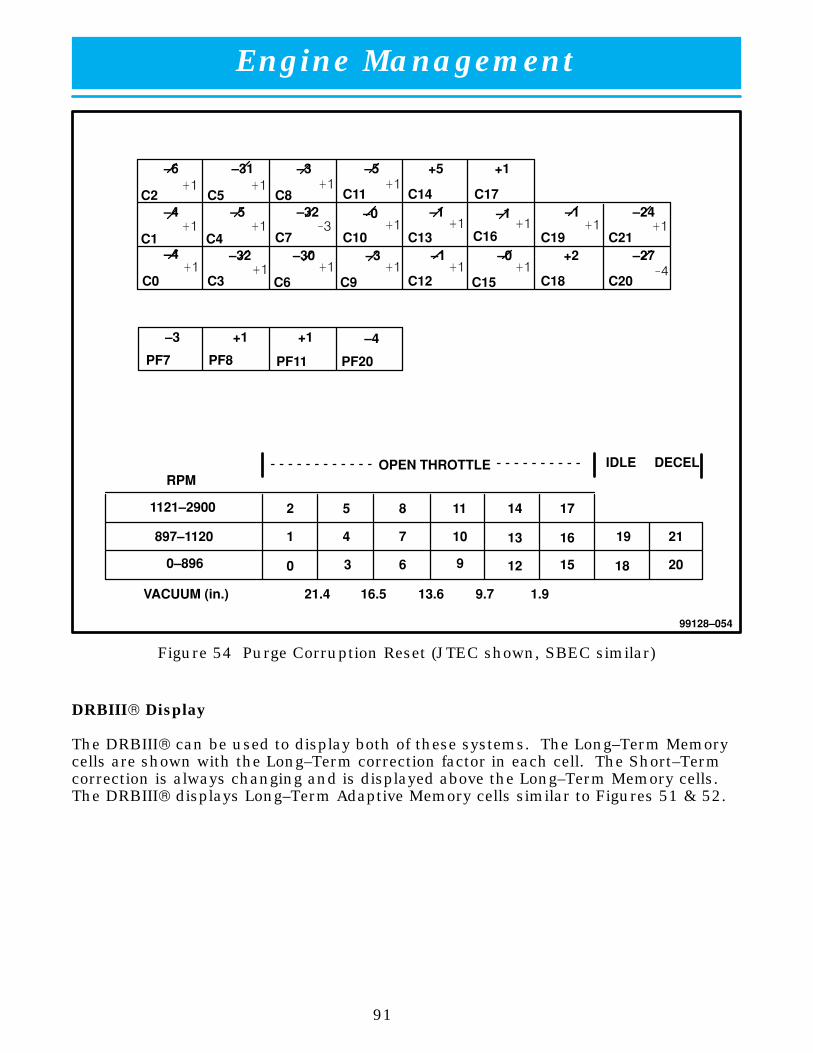
Engine Management
91
99128–054
OPEN THROTTLE IDLE DECEL
VACUUM (in.)
RPM
1121–2900
897–1120
0–896
2 5 8 11 14 17
1
0
4
3
7
6
10
9
13
12
16
15
19 21
18 20
21.4 16.5 13.6 9.7 1.9
–6
C2
–31 –3 –5 +5 +1
–1 –1 –24–1–0–32–5–4C5 C8 C11 C14 C17
–4
C0
C1 C4–32
C3
C7–30 –3 –1 –0 +2 –27
C6 C9 C12 C15 C18 C20
–3 +1 +1 –4
PF7 PF8 PF11 PF20
C10 C13 C16 C19 C21
�� �� �� ��
�� �� �� �� �� �� ��
�� �� �� �� �� ��
��
��
Figure 54 Purge Corruption Reset (JTEC shown, SBEC similar)
DRBIII Display
The DRBIII can be used to display both of these systems. The Long–Term Memorycells are shown with the Long–Term correction factor in each cell. The Short–Termcorrection is always changing and is displayed above the Long–Term Memory cells.The DRBIII displays Long–Term Adaptive Memory cells similar to Figures 51 & 52.

Engine Management
92
BRAKE SWITCH
When the brakes are applied, the brake switch provides an input to the PCM fordeceleration fuel management. The brake switch is equipped with three sets ofcontacts, one normally open and the other two normally closed (brakes disengaged).The PCM sends a 12–volt signal to one of the normally closed contacts in the brakeswitch, which is connected to a ground (fig. 55). With the contacts closed, the12–volt signal is pulled to ground, causing the signal to go low. The low–voltagesignal, monitored by the PCM, indicates that the brakes are not applied. When thebrakes are applied, the contacts open, causing the PCM’s output voltage to go high.
99128–055
ÁÁÁÁ
1
ÁÁÁÁÁÁ
2
ÁÁÁÁ
3ÁÁÁÁ
4ÁÁÁÁÁÁ
5
Figure 55 Brake Switch Circuit
1 Powertrain Control Module 4 Brake (Stop Lamp) Switch
2 Voltage Level Detection Circuit 5 From Battery
3 To Stop Lamps

Engine Management
93
Component Location
The brake switch is located rearward of the brake pedal and is attached to the brakepedal sled (fig. 56).
99128–056
ÁÁÁÁÁÁ
1ÁÁÁÁÁÁ
2ÁÁÁÁÁÁ
3
ÁÁÁÁ
4
Figure 56 Brake (Stop Lamp) Switch
1 Brake (Stop Lamp) Switch 3 Brake Pedal
2 Switch Bracket 4 Striker
CLUTCH PEDAL POSITION (CPP) SWITCH
The CPP Switch is installed in series between the ignition switch and the coil batteryterminal of the starter relay. This normally open switch prevents the Starter Relayfrom being energized unless the clutch pedal is depressed. This prevents starteroperation while the clutch disc and flywheel are engaged. The Starter Relay isalways grounded.

Engine Management
94
VEHICLE SPEED SENSOR (VSS)
Vehicle speed is transmitted to the PCM via the VSS, which is located in thetransmission extension housing. The PCM requires the VSS to control the followingprograms:
� IAC motor (during deceleration)
� Injection pulse width (during deceleration)
� OBD II diagnostics (JTEC only)
� PCM mileage EEPROM
� Road speed shutdown
� Speedometer/Odometer
Note: Road speed shutdown is the PCM shutting off fuel injectors above a presetvehicle speed and rpm.
The VSS is a Hall–effect sensor. This sensor is mechanically driven by a pinion gearthat is located on the output shaft of the transmission. The Hall–effect sensorswitches a 5–volt signal sent from the PCM from a ground to an open circuit at arate of ten pulses per transmission output shaft revolution. When the PCM countsa specific number of pulses (10,000), it assumes it has traveled one mile. The JTECsythesizes the signal from the VSS input to feed the speedometer, EES system, andradio.
Like all Hall–effect sensors, the sensor electronics need a power source. On JTEC,this power source, the secondary 5–volt supply, is provided by the PCM (fig. 57). OnSBEC, this power source is the same 9–volt supply that is used by the CMP andCKP sensors (fig. 58).
Vehicle Speed Sensor Diagnostics
If the ECT indicates a warm engine while MAP and engine indicate vehiclemovement and there is no VSS signal, a rationality fault will be set.

Engine Management
95
99128–057
VEHICLESPEED SENSOR
5V
0 VS 8SR=10,000 PULSES
SENSOR SIGNAL
Figure 57 JTEC Vehicle Speed Sensor Circuit
CRANKSHAFT
CAMSHAFT
A/DCONVERTER
9 VOLTREGULATOR
VEHICLESPEED SENSOR
5V
5V
0 VS 8SR=10,000 PULSES
SENSOR SIGNAL
99128–058
Figure 58 SBEC Vehicle Speed Sensor Circuit

Engine Management
96
FUEL–LEVEL SENSOR INPUT
Fuel level is an input that is used as a disabler for OBD II (JTEC). From 1996–1997there is a low fuel level switch. From 1996–2000 the fuel level is input directly tothe PCM (fig. 59).
12 volts is supplied from the dash gauge to the fuel level sensor and the PCM. ThePCM measures the voltage drop across the resistor of the sensor.
99128–059
ÁÁÁÁÁÁÁÁÁÁÁÁÁÁ1 ÁÁÁÁÁÁÁÁÁÁÁÁÁÁ2
ÁÁÁÁÁÁÁÁÁÁÁÁ
3
ÁÁÁÁÁÁ
ÁÁÁÁÁÁÁÁ4
ÁÁÁÁÁÁ
ÁÁÁÁÁÁÁÁÁÁ
5
Figure 59 Fuel Level Gauge Circuit
1 1992–1995 4 1998–2000 Only
2 1996–2000 5 All Years
3 1996–1997 Only

Engine Management
97
BATTERY/AMBIENT TEMPERATURE SENSOR
1996 Coupe/1997–2000 All Vipers
The PCM uses an input from the Battery/Ambient Temperature Sensor (BTS)located on the battery tray. The function of the BTS is to enable control of thegenerator output, based upon ambient temperature. As temperature increases, thecharging rate should decrease (Table 4). As temperature decreases, the chargingrate should increase. The PCM maintains the maximum output of the generator bymonitoring battery voltage and controlling battery voltage to a range of 13.5–14.7volts.
The BTS is also used for OBD II diagnostics. Certain faults and OBD II monitors areeither enabled or disabled, depending upon BTS input (for example, disable purgeand EGR (if equipped) enable LDP and O2 heater test). Most OBD II monitors aredisabled below 20°F.
If the BTS indicates a voltage that is too high or too low, the PCM sets a DTC. Whenthe DTC is set, the MIL is illuminated and the PCM moves into limp–in mode. Inlimp–in, the PCM will substitute a preset value. Using this substitute temperature,the PCM changes to a preset target–charging system voltage.
Table Four Charging Rates
Battery Temperature (°F) Target Charging Rate
–4 15.19 – 14.33
32 14.82 – 13.96
68 14.51 – 13.65
104 14.08 – 13.22
144 13.77 – 13.04
1996 Viper Roadster
These vehicles use an Ambient Temperature Sensor as part of OBD II diagnostics.The ambient sensor is located behind the front fascia toward the drivers side. Referto the OBD II training course for more information. The charging systems on thesevehicles are not controlled by the PCM and therefore a battery temperature sensor isnot needed. The generator on SBEC vehicles has an internal voltage regulator thatis not controlled by the PCM.
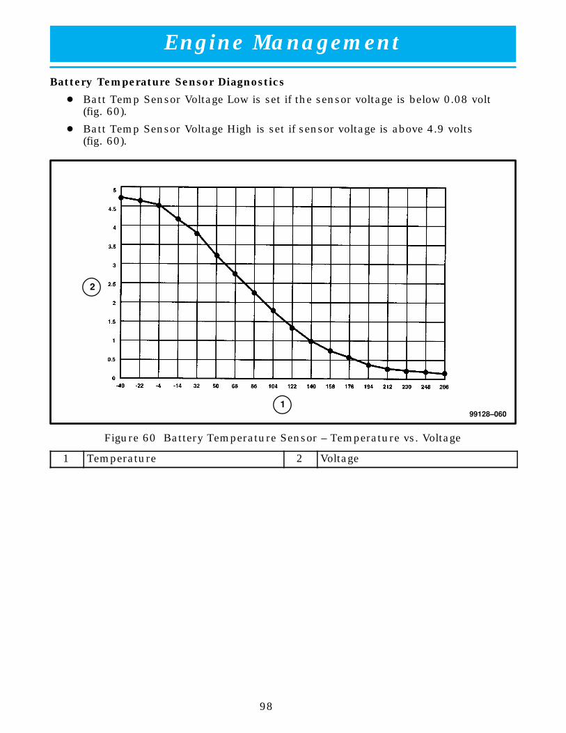
Engine Management
98
Battery Temperature Sensor Diagnostics
� Batt Temp Sensor Voltage Low is set if the sensor voltage is below 0.08 volt(fig. 60).
� Batt Temp Sensor Voltage High is set if sensor voltage is above 4.9 volts(fig. 60).
99128–060
ÁÁÁÁÁÁ
1
ÁÁÁÁÁÁ
2
Figure 60 Battery Temperature Sensor – Temperature vs. Voltage
1 Temperature 2 Voltage

Engine Management
99
99128–061
Figure 61 Battery Temperature Sensor – Resistance vs. Temperature

Engine Management
100
AIR CONDITIONING SWITCH
When the A/C–heater control switch is moved to an A/C position or the Defrostposition, the PCM A/C select circuit is pulled low when ground is provided throughthe dash panel switch (figs. 62 & 63). The PCM request circuit is also pulled low ifthe A/C Pressure Switches and Thermostatic Switch are closed. Refer to the BodyElectrical book for more information on A/C Operation.
99128–062
A/CREQUEST
34 �F OPENS40 �F CLOSES
LOW PRES. SW.OPENS AT 28 PSI
CLOSES AT 36 PSIHIGH PRES. SW.
OPENS AT 455 PSICLOSES AT 369 PSI
A/C HIGH/LOWPRESSURESWITCHES
TEMPERATURESWITCH
DASHSWITCH
12v
VOLTAGE
PCM
LEVELDETECTION
VOLTAGELEVEL
DETECTION
12v
A/CSELECT
Figure 62 JTEC A/C Switch Circuit
99128–063
A/CREQUEST
34 �F OPENS40 �F CLOSES
LOW PRES. SW.OPENS AT 28 PSI
CLOSES AT 36 PSIHIGH PRES. SW.
OPENS AT 455 PSICLOSES AT 369 PSI
A/C HIGH/LOWPRESSURESWITCHES
TEMPERATURESWITCH
DASHSWITCH
12v
EDGEDETECTION
PCM
Figure 63 SBEC A/C Switch Circuit

Engine Management
101
NOTES:

Engine Management
102
FUEL INJECTION SYSTEM – PCM OUTPUTS
SOLENOID AND RELAY CONTROL (JTEC)
Most of the output relays and solenoids are controlled by quad drivers. A quaddriver is a single microchip that contains four separate driver circuits that are usedfor controlling high current output devices.
A voltage divider circuit has been added to diagnose the operation of the drivercircuit. This voltage divider is located between the output of the driver and theinput command (from microprocessor) to the driver.
99128–064
Figure 64 JTEC Sense Circuit
There is a sense circuit located at the microprocessor on the input command line tothe driver. When the command is OFF, the 12 volts from the relay coil will gothrough the voltage divider leaving 6 volts at the sense point. Therefore, an OFFcommand will look for voltage to be high (fig. 64).
When the command is ON, the micro closes a circuit allowing the 6 volts to go toground. This energizes the driver. When the driver is energized, the 12 volts areallowed to go to ground through the driver. Once this occurs, the voltage at thesense point goes low. Therefore, an ON command will look for voltage to be low.
Because of this design, the PCM is capable of continuous diagnostics, without theneed for a request to change state.
When the key is first turned on, some relays and solenoids are actuated very quickly(before engine starts) to verify the circuitry.

Engine Management
103
Once the key is turned on, the sense point is continuously monitored. If a circuitopens or a short to ground occurs when the requested state is off, a fault will be set.However, if a circuit should open or short to ground when the requested state is ON,this will not be detected until the state is changed to OFF. This is due to the factthat when the state is ON, the circuit is already low, so it is not possible to knowthat an open has occurred.
Caution: Both diode– and resistor–suppressed relays have been used, If an incorrectrelay is used, damage may occur to the relay, circuit or PCM.
SOLENOID AND RELAY CONTROL (SBEC)
Most of the output relays and solenoids are controlled by a serial peripheralinterface/output (SPIO) circuit. This circuit, within the PCM, is used for controllinghigh current output devices. The SPIO has the added advantage of being able toprovide diagnostics.
The SPIO circuit gives the PCM the ability to determine whether the actual state ofthe relay or solenoid matches the PCM’s expected state.
The PCM performs diagnostics only when a change of state has been requested.This means that the circuit could go bad and the PCM would not know it until itwas told to change the state.
Caution: Both diode– and resistor–suppressed relays have been used. If an incorrectrelay is used, damage may occur to the relay, circuit or PCM.

Engine Management
104
AUTOMATIC SHUTDOWN RELAY (ASD) (JTEC)
When energized, the ASD Relay provides power to operate the injectors, ignition coil,generator field (1996–2000) and O2 Sensor heaters (upstream and downstream). Italso provides a sense circuit to the PCM for diagnostic purposes. The PCM energizesthe ASD:
� Anytime there is a Crankshaft Position Sensor signal that exceeds apredetermined value.
� For approximately 1.8 seconds during the initial key–ON cycle.
The ASD Relay electromagnet is provided with battery voltage from the ignitionswitch (fig. 65). The PCM provides the ground.
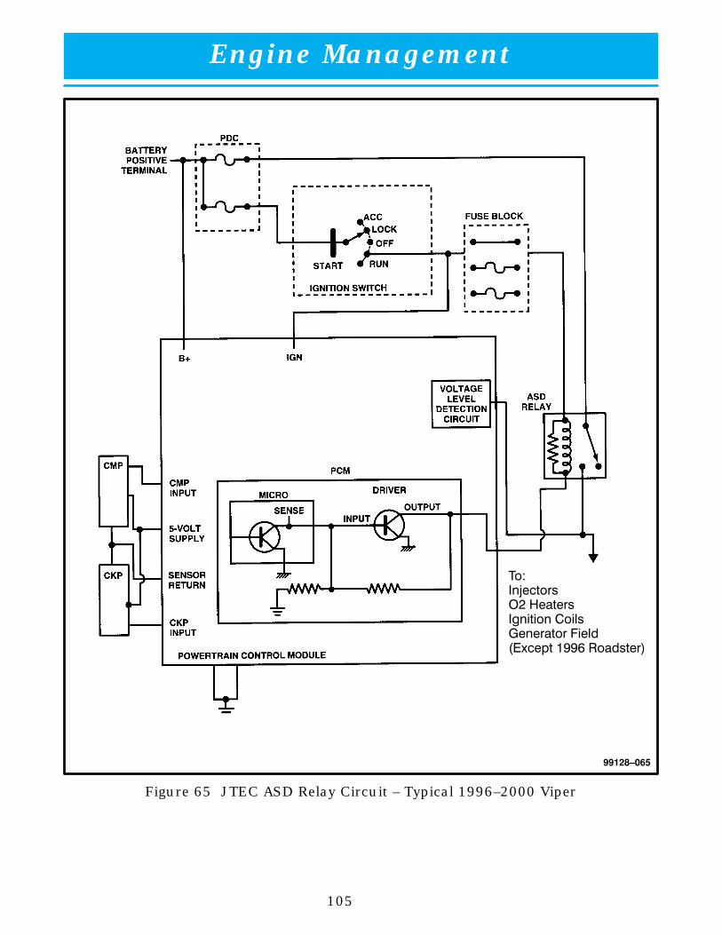
Engine Management
105
99128–065
����������� ������������ ����������� ����������� ���� �������
Figure 65 JTEC ASD Relay Circuit – Typical 1996–2000 Viper

Engine Management
106
AUTOMATIC SHUTDOWN RELAY (ASD) (SBEC)
When energized, the ASD Relay provides power to operate the injectors, ignition coil,O2 sensor heaters, and also provides a sense circuit to the PCM for diagnosticpurposes. The PCM energizes the ASD Relay:
� Anytime there is a CKP Sensor signal that exceeds a predetermined value.
� For approximately 0.7 to 1.5 seconds during the initial key–ON cycle. Thedetermining factor for the latch time is ECT. A cold engine will allow a longerlatch time to overcome slower cranking speed.
The ASD Relay’s electromagnet is fed battery voltage, not ignition voltage (fig. 66).The PCM still provides the ground. As mentioned earlier, the PCM energizes theASD Relay during an O2 sensor heater test. This test is performed only after theengine has been shut off. The PCM still operates internally to perform severalchecks, including monitoring the O2 heaters. This and the other DTC tests areexplained in detail in the On–Board Diagnostic II Student Reference Book.
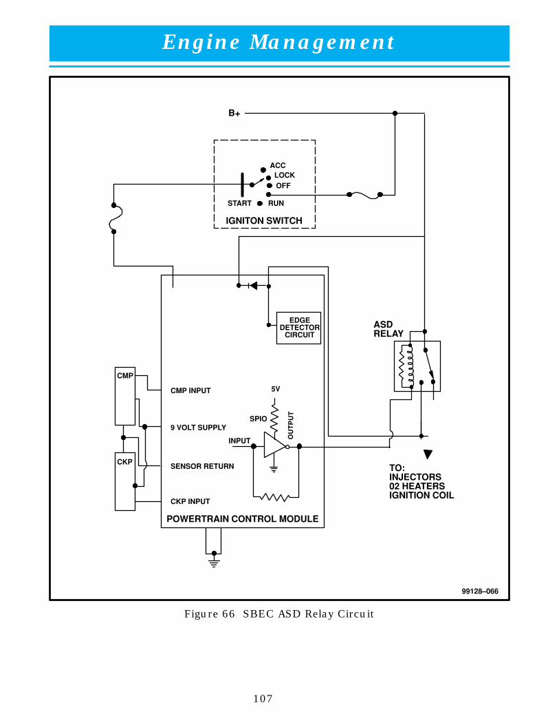
Engine Management
107
99128–066
5V
B+
IGNITON SWITCH
TO:INJECTORS02 HEATERSIGNITION COIL
ASDRELAY
LOCKACC
OFF
RUNSTART
CMP
CKP
CMP INPUT
9 VOLT SUPPLY
SENSOR RETURN
CKP INPUT
INPUT
SPIO
EDGEDETECTOR
CIRCUIT
POWERTRAIN CONTROL MODULE
Figure 66 SBEC ASD Relay Circuit

Engine Management
108
FUEL PUMP RELAY
The Fuel Pump Relay is energized to provide power to operate the fuel pump underthe following conditions:
� For approximately 1.8 seconds during the initial key–ON cycle.
� While the CKP Sensor is providing an rpm signal that exceeds a predeterminedvalue.
Ignition voltage is provided to the Fuel Pump Relay electromagnet any time the keyis in the RUN position (fig. 67). The PCM provides the ground control to energize therelay. Unlike previous Chrysler systems, the Fuel Pump Relay does not providepower to operate the O2 Sensor heaters.
99128–067
Figure 67 Fuel Pump Relay Circuit
The relay is energized when the key is cycled to RUN in order to prime the fuel railwith liquid fuel, allowing for a quick start–up. Anytime the CKP Sensor indicatesthat there is an rpm signal that exceeds a predetermined value, the relay isenergized to ensure proper fuel pressure and volume during engine cranking andrunning conditions. Anytime the CKP Sensor signal is lost (engine has been shutoff, or the sensor indicates no rpm), the Fuel Pump Relay is de–energized.

Engine Management
109
NOTES:

Engine Management
110
FUEL INJECTORS
The PCM provides battery voltage to each injector through the ASD Relay (figs. 68 &69). Injector operation is controlled by a ground path, provided for each injector bythe PCM. Injector on–time (pulse width) is variable, and is determined by theduration of the ground path provided.
99128–068
Figure 68 JTEC Fuel Injection Circuit
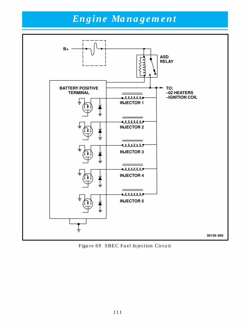
Engine Management
111
99128–069
ASDRELAY
TO:–02 HEATERS–IGNITION COIL
BATTERY POSITIVETERMINAL
INJECTOR 1
INJECTOR 2
INJECTOR 3
INJECTOR 4
INJECTOR 5
B+
Figure 69 SBEC Fuel Injection Circuit

Engine Management
112
Fuel Injector Diagnostics
To diagnose an injector, the PCM monitors the voltage spike created by the collapseof the magnetic field through the injector coil. The inductive kick is approximately60 volts (fig. 70). Any condition that restricts maximum current flow would notallow the kick to occur, resulting in an injector fault.
See the description of fuel injectors in the Fuel System Components Section of thisreference guide, for further information.
99128–070
ÁÁÁÁ
1
ÁÁÁÁÁÁÁÁÁ
2
ÁÁÁÁ
3
Figure 70 Injector Spike
1 Volts 3 Pulse Width
2 Kick

Engine Management
113
IGNITION COILS
Note: On SBEC/VIC vehicles, the ignition coils are controlled by the VIC. On JTECvehicles, the ignition coils are controlled by the PCM.
The PCM provides battery voltage to the ignition coils through the ASD Relay(fig. 71). Coil operation is controlled by a ground path provided to the coil by thePCM. The ignition coil fires a spark plug at every power stroke.
The PCM determines when to fire the coil, based on CMP and CKP Sensor inputs.The ignition coil primary is joined to the power wire from the ASD Relay. The ASDRelay provides battery feed to the ignition coil, while the PCM provides a groundcontact for energizing the coil. When the PCM breaks the ground contact, powertransfers from the primary to the secondary, causing the spark.
Resistance on the primary side of the coil should be between 0.51 and 0.61 ohms.The resistance of the secondary side is between 11,500 and 13,500 ohms. The coilhas the ability to provide up to 40,000 volts, if needed.
99128–071
ÁÁÁÁÁÁ
1
ÁÁÁÁ
2
ÁÁÁÁÁÁÁÁÁ
3
ÁÁÁÁÁÁ
4
PCM
Figure 71 Ignition Control Circuit
1 12V From ASD Relay 3 Coil Drivers
2 Ignition Coil Pack 4 Ignition Coil Pack

Engine Management
114
Coil Operation
When a conductor is formed into a coil, the magnetic field is many times strongerthan that of a single straight connector. To increase the strength of the magneticfield, you must either increase the number of loops in the coil, increase the amountof current flowing in the coil, or use a low–reluctance material for the core of thecoil.
If one coil is placed near another coil, and the first coil is connected to a current, theexpanding magnetic field induces a current into the second coil. The currentinduced into a coil is much higher than a current induced into a straight conductor.The coil that carries current: into this type of induction system is the primarywinding of the coil. The coil into which electromotive force is induced, is thesecondary winding of the coil. This mutual induction is the principle behindautomotive ignition coils.
To induce a current, the magnetic field must be moving. Once the magnetic fieldhas stabilized and is not expanding through the secondary conductor, no current isinduced in the secondary conductor. As the field collapses, the lines of force passthrough the secondary winding, which now induces a current in the oppositedirection. When the field has completely collapsed, current flow in the secondaryconductor stops.
The amount of secondary voltage generated depends on the amount of flux, thenumber of turns in the secondary coil, and the speed at which the primary currentis interrupted. “Flux” refers to the lines of force in motion, which create a magneticfield. The amount of flux depends on the primary circuit. More current in thiscircuit means more flux. The flux moves through the windings of the secondarycoil, so, more turns in the secondary coil result in more voltage. Flux collapsesthrough the secondary coil when the primary current is interrupted. A quickinterruption causes the flux to cut through the secondary windings faster. Aquicker interruption results in more secondary voltage than a slow interruption.
DIS coils can be arranged in various alternations of polarity. It really does notmatter if a spark fires positive or negative, as long as there is enough charge tojump the spark plug gap. The V10 engine uses 2 separate coil packs. One coil packis for cylinders 1 & 6, 7 & 4, and 3 & 2 while the other coil pack is for cylinders 5 &10 and 9 & 8.
The spark from a DIS coil moves from tower to tower using the block as a piece ofwire to complete the circuit. This means that if any part of the circuit opens, bothspark plugs will not fire. A spark will jump across the tip of the spark plug stillconnected to a coil tower. However, this spark is created by a capacitance effect andwill not support a load on the engine.
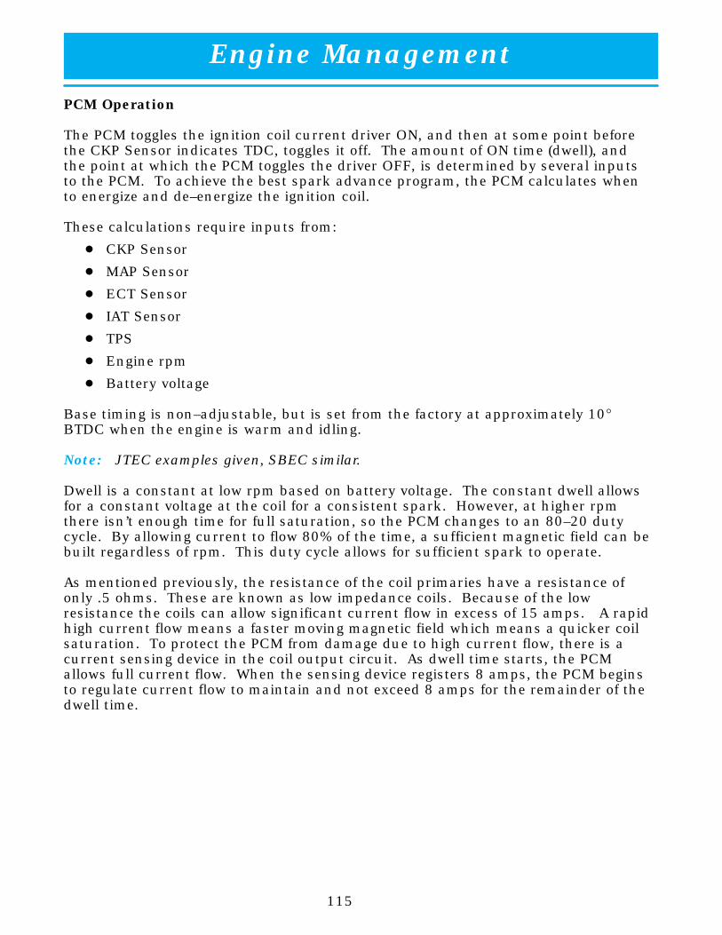
Engine Management
115
PCM Operation
The PCM toggles the ignition coil current driver ON, and then at some point beforethe CKP Sensor indicates TDC, toggles it off. The amount of ON time (dwell), andthe point at which the PCM toggles the driver OFF, is determined by several inputsto the PCM. To achieve the best spark advance program, the PCM calculates whento energize and de–energize the ignition coil.
These calculations require inputs from:
� CKP Sensor
� MAP Sensor
� ECT Sensor
� IAT Sensor
� TPS
� Engine rpm
� Battery voltage
Base timing is non–adjustable, but is set from the factory at approximately 10°BTDC when the engine is warm and idling.
Note: JTEC examples given, SBEC similar.
Dwell is a constant at low rpm based on battery voltage. The constant dwell allowsfor a constant voltage at the coil for a consistent spark. However, at higher rpmthere isn’t enough time for full saturation, so the PCM changes to an 80–20 dutycycle. By allowing current to flow 80% of the time, a sufficient magnetic field can bebuilt regardless of rpm. This duty cycle allows for sufficient spark to operate.
As mentioned previously, the resistance of the coil primaries have a resistance ofonly .5 ohms. These are known as low impedance coils. Because of the lowresistance the coils can allow significant current flow in excess of 15 amps. A rapidhigh current flow means a faster moving magnetic field which means a quicker coilsaturation. To protect the PCM from damage due to high current flow, there is acurrent sensing device in the coil output circuit. As dwell time starts, the PCMallows full current flow. When the sensing device registers 8 amps, the PCM beginsto regulate current flow to maintain and not exceed 8 amps for the remainder of thedwell time.

Engine Management
116
IDLE AIR CONTROL (IAC) STEPPER MOTOR
Description
The IAC stepper motor is mounted to the front of the intake manifold, and regulatesthe amount of air bypassing the control of the throttle plate (figs. 72 & 73). Asengine loads and ambient temperatures change, engine rpm also changes. A pintleon the IAC stepper motor protrudes into a passage connected to both intakemanifold plenums, controlling airflow through the passage. The IAC is controlled bythe PCM to maintain the target engine idle speed.
At idle, engine speed can be increased by retracting the pintle and allowing more airto pass through the port, it can be decreased by restricting the passage with thepintle and diminishing the amount of air bypassing the throttle plate.
When engine rpm is above idle speed, the LAC is used for the functions listed below.
� Off–idle dashpot
� Deceleration airflow control
A/C compressor load control (also opens the passage slightly before the compressoris engaged so that the engine rpm does not dip down when the compressor engages).
The PCM can control polarity of the circuit to control direction of the stepper motor.
99128–072
Figure 72 IAC Stepper Motor (1994–2000)

Engine Management
117
99128–073
ÁÁÁÁ
1
ÁÁÁÁ
2
ÁÁÁÁ
3ÁÁÁÁ
4
Figure 73 IAC Stepper Motor (1992–1993)
1 IAC Motor 3 Thermostat Housing
2 Fuel Rail Inlet 4 Fuel Pressure Line
Operation
The IAC is called a stepper motor because it is moved in “steps.” The IAC motor iscapable of 255 total steps, from fully closed to fully open. Opening the IAC in turnopens an air passage around the throttle blade which increases rpm.
The PCM uses the IAC motor to control idle speed (along with timing) and to reach adesired MAP during decel (keep engine from stalling).
The stepper motor has four wires (figs. 74 & 75). Two wires are for 12 volts. Theother two wires are for ground. The stepper motor is not really a motor at all. Thepintle that moves in and out can be thought of as a bolt with threads (fig. 76). The“nut” is a permanent magnet. There are two windings by the permanent magnet.When the PCM energizes one set of windings, this makes an electromagnet. Thepermanent magnet, which is allowed to rotate, is attracted to the electromagnet androtates until the north and south poles line up. Once the poles line up, the nutstops turning. At this time, the PCM will energize the other winding. This movesthe “nut” one more step. As the nut turns, the pintle (bolt) moves out or in.

Engine Management
118
To make the IAC move in the opposite direction, the PCM just reverses polarity onboth windings. If only one wire is open, the IAC can only be moved one step ineither direction.
Note: To keep the IAC motor in position when no movement is needed, the PCM willenergize both windings at the same time. This locks the IAC motor in place.
99128–074
Figure 74 JTEC IAC Motor Control Circuit

Engine Management
119
99128–075
Figure 75 SBEC IAC Motor Control Circuit

Engine Management
120
In the IAC motor system, the PCM will count every step that the motor is moved.This allows the PCM to “know” the motor pintle position. If the memory is cleared,the PCM no longer knows the position of the pintle. So, at the first key–ON, thePCM drives the IAC motor closed, regardless of where it was before. This “zeros” thecounter. From this point, the PCM will back out the IAC motor and keep track of itsposition again.
99128–076
ÁÁÁÁ1
ÁÁÁÁÁÁÁÁÁ
2
ÁÁÁÁ
3
ÁÁÁÁÁÁ
4
Figure 76 IAC Internal View
1 Coil A 3 Rotor Magnet
2 Coil B 4 Pintle Seat

Engine Management
121
NOTES:

Engine Management
122
IAC Stepper Motor Program
When the pintle has completely blocked the air passage, the IAC stepper motor is atstep zero (fig. 77). The PCM has the authority to increase the opening byapproximately 255 steps. The IAC stepper motor cannot identify in exactly whichposition the pintle is, so the PCM has a program that enables it to learn the positionof the IAC pintle.The program begins by learning step zero. This is accomplished by the PCM drivingthe IAC stepper motor closed for several seconds (when the key is first turned to theRUN position, after a battery disconnect). The PCM assumes, at the end of thecycle, the IAC stepper motor should be at step zero. Once the stepper motor findsstep zero, the PCM backs the motor to the open position. The number of stepsneeded to arrive at the open position is based upon information delivered by theECT sensor. The program can be updated by the DRBIII, or by disconnectingbattery voltage from the PCM and then reconnecting it.The PCM is also equipped with a memory program that records the number of stepsthe IAC stepper motor most recently advanced to during a certain set of parameters.For example: The PCM was attempting to maintain a 750 rpm target during a hotstart–up cycle. The last recorded number of steps for that may have been 27. Thatvalue would be recorded in the memory cell, so that the next time the PCMrecognizes the identical conditions, the PCM recalls that 27 steps were required tomaintain the target. This program allows for greater customer satisfaction due togreater control of engine idle.
99128–077
ÁÁÁÁ
1
ÁÁÁÁ
2
ÁÁÁÁÁÁÁÁÁ
3
ÁÁÁÁÁÁ
4
Figure 77 IAC Motor
1 Stator I 3 Coil B1
2 Stator II 4 Pintle Seat

Engine Management
123
Another function of the memory program during the key cycle occurs when the A/Crequest circuit requires the IAC stepper motor to control engine rpm. This is therecording of the last targeted steps.
As mentioned earlier, the PCM can “anticipate” compressor loads. This isaccomplished by delaying compressor operation for approximately 0.5 second, untilthe PCM moves the IAC stepper motor to the recorded steps that were loaded intothe memory cell. Using this program helps eliminate idle–quality changes as loadschange.
Target Idle
Target idle is determined by the ECT Sensor.
IAC Motor Position
The IAC motor position is determined by the following inputs:
� ECT Sensor
� Battery Voltage
� Vehicle Speed (VSS)
� Throttle angle (TPS)
� MAP
� RPM
� A/C Compressor
IAC Stepper Motor Service
Anytime the IAC stepper motor or its circuit is serviced, the IAC memory cell mustbe updated. Use the DRBIII to “Reset IAC.” This ensures that the PCM canidentify step zero. Also, be sure that when the IAC stepper motor is installed intothe throttle body, the passage is clear of debris and that the pintle does notprotrude too much. Before installing an IAC motor, make sure that the pintle is in aretracted position. This will ensure that the pintle and seat are not damaged whenthe IAC motor is installed.
IAC Diagnostics (JTEC)
IAC Diagnostics have changed with the use of JTEC. Open circuits are diagnosed ifthey are present at key–ON. However, if a driver circuit opens while the engine isrunning, it will not be diagnosed until the next key–ON cycle.
Short circuits to B+ and ground are diagnosed at key–ON and also while the engineis running.

Engine Management
124
RADIATOR FAN RELAYS
The fan(s) are turned on by the temperature of the coolant which is sensed by theECT Sensor which sends the message to the PCM. The PCM turns on the fanthrough the Fan Relay(s). Switching through the PCM provides fan control for thefollowing conditions:
� The fan(s) will not run during cranking until the engine starts no matter whatthe coolant temperature is.
� The low speed fan will run when the A/C is ON.
� The high speed fan will run when the PCM is in limp mode.
� Fan control is accomplished based on coolant temperature. Refer to Table 5for fan operation data related to coolant temperature.
� Fan control is also dependent upon vehicle speed. On vehicles from1992–1993, the fan will run at vehicle speeds above 40 mph only if coolanttemperature reaches 110° C (230° F). It will turn off when the temperaturedrops to 104° C (220° F). At speeds below 40 mph, the fan switches on at99° C (210° F) and off at 93° C (200° F).
� To help prevent steaming, the fan will run only below 16° C (60° F) ambient.Between 38° C (100° F) to 97° C (195° F) coolant temperature, at idle, and thenonly for three minutes.
Table Five Radiator Fan On/Off Values
A/C OFF Low Speed High Speed
Fan On 97° C (207° F) 102° C (216° F)
Fan Off 93° C (199° F) 97° C (207° F)
A/C ON
Fan On 0° C (32° F) 101° C (214° F)
Fan Off –4° C (25° F) 96° C (205° F)
Note: The values shown above are approximate, and may vary between vehicles. Onvehicles with dual radiator fans, both fans operate at the same time at slightlydifferent speeds.

Engine Management
125
1992–1995 SBEC Radiator Fans
From 1992–1993, Vipers were equipped with a dual–fan, single–speed radiator fansystem (fig. 79). The Radiator Fan Relay on these vehicles was mounted on theheater housing, just below the blower motor (fig. 78). From 1994–1995, Vipersreceived a single–fan, dual speed radiator fan system (fig. 80). This change madethe addition of a High Speed Fan Relay necessary.
99128–078
ÁÁÁÁ
1
ÁÁÁÁ
2ÁÁÁÁÁÁ
3
ÁÁÁÁÁÁ
4
ÁÁÁÁ
5
ÁÁÁÁÁÁ
6
ÁÁÁÁ
7
Figure 78 Radiator Fan Relays
1 Heater Blower Motor 5 Heater Housing
2 A/C Relay (1994 only) 6 A/C Relay (1993 only)
3 Starter Relay 7 Radiator Fan Relay (1994 only)
4 ASD Relay

Engine Management
126
A/C
M
M
PCM
SPIO
SPIO
FANRELAY
B+
A/C COMPRESSORCLUTCH RELAY
IGNITION SWITCHRUN–START
99128–079
Figure 79 1992–1993 Dual Radiator Fan Circuit

Engine Management
127
A/C
PCM
SPIO
SPIO
RADIATOR FANON RELAY
B+
A/C COMPRESSORCLUTCH RELAY
IGNITION SWITCH
B+IGNITIONSWITCH
HIGH
RADIATOR FANHIGH/LOW RELAY
99128–080
Figure 80 1994–1995 Single Radiator Fan Circuit

Engine Management
128
1996–2000 JTEC Radiator Fans
The two Radiator Fan Relays on the 1996 Roadster are located in the same spot asthe 1992–1995 Roadsters (right hand side of engine compartment). On 1996Coupes, and all Vipers from 1997 forward, the Radiator Fan Relays are located inthe Power Distribution Center (PDC).
Radiator Fan ON Relay
The Radiator Fan ON Relay energizes when the PCM provides a ground to the relay.
In 1996, the cooling fan was turned off at 62 mph during acceleration and turnedback on at 52 mph during deceleration. In 1997, the fan is turned off at 77 mphduring acceleration and turned back on at 67 mph during deceleration.
Radiator Fan Low/High Relay
The Radiator Fan LOW/HIGH Relay works in conjunction with the Radiator Fan ONRelay (fig. 81). If the coolant temperature is below 102° C (216° F) the current flowfor the fan is through the normally closed contacts of the LOW/HIGH relay. If thecoolant temperature is above 102° C (216° F), the PCM grounds the LOW/HIGHRelay and the radiator fan changes to high speed. The PCM turns off high speed fanoperation when coolant temperature drops to 102° C (216° F). The low speed willcontinue until temperature drops below 94° C (120° F).

Engine Management
129
99128–081
ÁÁÁÁ
1
ÁÁÁÁ
2
ÁÁÁÁÁÁ
3
ÁÁÁÁÁÁÁÁÁ
4
ÁÁÁÁÁÁ
5ÁÁÁÁÁÁ
6
Figure 81 1996–2000 Radiator Fan Circuit
1 Battery Positive Terminal 4 Radiator Fan LOW/HIGH Relay
2 Ignition Switch 5 Radiator Fan Motor
3 Radiator Fan ON Relay 6 PCM

Engine Management
130
GENERATOR FIELD CONTROL – 1992–1996 ROADSTER
Generator field control is accomplished through the use of a voltage regulator whichis internal to the generator. The charging system voltage on these vehicles is notcontrolled by the PCM.
GENERATOR FIELD CONTROL – EXCEPT 1992–1996 ROADSTER
The PCM regulates charging system voltage and determines the final goal or “targetcharging voltage.” The target charging voltage is controlled mainly by the batterytemperature sensor, which is located under the battery tray. Power to the generatorfield wiring is supplied by the ASD Relay (fig. 82).
The PCM monitors battery voltage. If it senses that battery voltage is more than 0.5volt lower than the target voltage, the PCM grounds the field winding until sensedbattery voltage is 0.5 volt above target voltage. A circuit in the PCM cycles theground side of the generator field up to 100 times per second (100 Hz), but has thecapability to ground the field control wire 100% of the time full field, to achieve thetarget voltage. If the charging rate cannot be monitored (limp–in), a duty cycle of25% is used by the PCM in order to have some generator output.
Note: Externally, the generators on the 1996 Viper look very similar. The generatorfor the Roadster has an internal voltage regulator while the Coupe is regulatedby the PCM. Do not interchange the generators.

Engine Management
131
99128–082
ÁÁÁÁÁÁÁÁÁ
10
ÁÁÁÁ
1
ÁÁÁÁÁÁÁÁÁ
2
ÁÁÁÁÁÁ
3
ÁÁÁÁÁÁ
4 ÁÁÁÁ
5
ÁÁÁÁÁÁÁÁÁ
6
ÁÁÁÁ
7
ÁÁÁÁÁÁ
8
ÁÁÁÁÁÁ
9
ÁÁÁÁ11
ÁÁÁÁÁÁ
12
Figure 82 Generator Field Control Circuit (1996 Coupe, 1997–2000 All)
1 Battery Temperature Sensor 7 Generator
2 PCM 8 Case Ground
3 A/D Converter 9 To Ignition Coil, Injectors, O2Heaters
4 Voltage Level Detection Circuit 10 Battery
5 ASD Relay Control 11 Fuse Link
6 ASD Relay 12 PDC Fuse

Engine Management
132
CHARGING SYSTEM INDICATOR LIGHT – 1992–1996 ROADSTER
As mentioned earlier, generator field control is accomplished through the use of aninternal voltage regulator in the generator, which is not affected by the PCM. Thecharging system indicator light is controlled directly by the generator.
CHARGING SYSTEM INDICATOR LIGHT – 1996 COUPE, 1997–2000 ALL
The PCM controls the operation of the charging–system indicator light, located inthe vehicle’s instrument cluster. The PCM provides a ground to complete the lampcircuit if a charging system fault is set (fig. 83).
99128–083
ÁÁÁÁ
ÁÁÁÁ
1
ÁÁÁÁÁÁ
2
ÁÁÁÁÁÁ
3
ÁÁÁÁÁÁ
4
Figure 83 Charging System Indicator Light (1996 Coupe, 1997–2000 All)
1 Under/Over Charge Indicator Light 3 Ignition Voltage
2 Tachometer 4 Tachometer Output
TACHOMETER
The PCM operates the tachometer which is located in the instrument panel. ThePCM provides duty–cycle output voltage to the tachometer. The frequency of theduty cycle is based upon engine speed which is calculated from inputs from the CKPSensor.

Engine Management
133
REVERSE LOCKOUT SOLENOIDThe reverse lockout solenoid is located at the rear of the transmission housing. Thereverse lockout solenoid prevents the operator from shifting into reverse when thevehicle speed is greater than 5 mph. When vehicle speed is less than 5 mph, thePCM provides a ground for the solenoid (energized) and allows shifting (fig. 84).When vehicle speed is greater than 5 mph, the solenoid is deactivated and preventsthe transmission from being shifted into reverse.
SKIP SHIFT SOLENOID AND INDICATOR LAMPThe skip shift solenoid is also located at the rear of the transmission housing. Theskip shift solenoid prevents the operator from shifting from first gear into secondand third gear during certain conditions. The PCM controls the skip shift solenoidand the skip shift indicator lamp (fig. 84). The lamp informs the driver that the shiftlever will be redirected to fourth gear, “skipping” 2nd and 3rd completely. The PCMlocks out second and third gear and illuminates the skip shift lamp when all of thefollowing conditions are met:
� Engine coolant exceeds 41° C (106° F)
� Vehicle speed is between 12 and 18 MPH
� Engine operating above 608 RPM
� The PCM verified first gear speed/RPM
� Throttle position sensor (TPS) signal is less than 0.68 volt above close throttle(23 percent throttle opening)
The program resets when vehicle speed drops below 2 MPH and is consideredcompleted once the conditions have exceeded, whether the trans was shifted or not.
99128–084
ÁÁÁÁ
1
ÁÁÁÁ
2
ÁÁÁÁ
3
Figure 84 Skip Shift and Reverse Lockout Solenoids
1 Fuse Block 3 Reverse Lockout Solenoid
2 Skip Shift Solenoid

Engine Management
134
MALFUNCTION INDICATOR LAMP (MIL)
Note: Only Vipers equipped with a JTEC PCM (1996 and Up) are OBD II compliant.
The MIL (CHECK ENGINE) lamp is located in the instrument cluster. The PCMoperates the MIL which illuminates for a three–second bulb test whenever theignition is turned ON. The MIL lamp remains continuously illuminated when anemissions component fails, or when the vehicle enters a limp–in mode. In limp–inmode, the PCM provides programmed inputs to keep the vehicle operational.
Because the vehicle is equipped with OBD II diagnostic capabilities (JTEC only), theMIL flashes if the onboard diagnostic system detects engine misfire severe enough todamage the catalytic converter. The vehicle should not be driven if this occurs.
Anytime the MIL is illuminated, a DTC is stored and the PCM must meet certaincriteria to extinguish the lamp. On vehicles equipped with OBD I diagnostics(1992–1995 Vipers), the MIL would normally extinguish after the problem thatcaused the MIL to illuminate was no longer present, and the key had been cycledfrom OFF to ON one time. However, on ALL JTEC vehicles, three consecutive “good”trips must occur to extinguish the MIL.
If a problem occurred with one of the main OBD II monitors, the PCM must pass thetest of the monitor that failed three consecutive times. On the fourth key–ONregister, the MIL is extinguished.
DTCs that were stored can be erased automatically only after the MIL has beenextinguished and 40 warm–up cycles have occurred or with the DRBIII.

Engine Management
135
Trip Definition – 1996–2000 Only
The term “trip” has different meanings depending on the circumstances. If the MIL(Malfunction Indicator Lamp) is OFF, a trip is when the Oxygen Sensor Monitor andthe Catalyst Monitor have been completed in the same drive cycle.
When any emission DTC is set, the MIL on the dash is turned ON. When the MIL isON, it takes three “good” trips to turn the MIL OFF. In this case, it depends on whattype of DTC is set to know what a trip is. The minimum requirement is enginerunning for 2 minutes with no faults detected.
For the Fuel Monitor or Misfire Monitor (continuous monitor), the vehicle must beoperated in the “Similar Condition Window” for a specified amount of time to beconsidered a good trip.
Non–continuous OBD II monitors include:
� Oxygen Sensor
� Catalyst Monitor
� Purge Flow Monitor
� Leak Detection Pump Monitor (if so equipped)
� Oxygen Sensor Heater Monitor
If any of these monitors fail twice in a row on two separate key cycles, turn on theMIL, and successfully rerun on the next start–up, it is considered a good trip.
Other examples of good trips are:
� Completion of 02 Sensor and Catalyst monitors after an emissions DTC (not anODB II monitor) is set.
� Engine run–time of two minutes if the Oxygen Sensor Monitor or CatalystMonitor have been stopped from running.
It can take up to two failures in a row to turn on the MIL. After the MIL is ON, ittakes three good trips to turn the MIL OFF. After the MIL is OFF, the PCM willself–erase the DTC after 40 warm–up cycles. A warm–up cycle is counted when theECT (Engine Coolant Temperature) sensor has crossed 160° F and has risen by atleast 40° F since the engine was started.
Refer to the OBD II course for additional information.

Engine Management
136
EVAPORATIVE PURGE SOLENOID
The PCM controls Evaporative Purge Solenoid operation and provides a ground paththat allows the solenoid to open. Refer to the Emission Control Systems section ofthis publication for more information.
LEAK–DETECTION PUMP SOLENOID (STARTING IN 1998)
The PCM energizes the Leak–Detection Pump Solenoid when specific operatingconditions have been met. Refer to the Emission Control Systems section of thispublication for more information.

Engine Management
137
NOTES:

Engine Management
138
EMISSIONS CONTROL SYSTEM
The emissions control system is comprised of evaporative emissions and exhaustemissions. Its function is to control the output of Hydrocarbons (HC), CarbonMonoxide (CO) and Oxides of Nitrogen (NOx). The PCM controls exhaust emissionsby monitoring the inputs and controlling Fuel and ignition systems. A three–waycatalyst is also used.
EVAPORATIVE EMISSION CONTROL
The evap control system consists of: fuel cap, rollover valves, vapor lines, filler neck,evap canister, Duty Cycle Purge (DCP) solenoid, and orifice. On some vehicles, thereis also an Evaporative System Leak Detection pump (fig. 85). For the 2000 modelyear the canister and LDP move to the rear of the vehicle.

Engine Management
139
99128–085
ÅÅ
ÁÁÁÁ
1
ÁÁÁÁ
2ÁÁÁÁÁÁÁÁÁ
3
ÁÁÁÁ
4ÁÁÁÁÁÁ
5
ÁÁÁÁ
6ÁÁÁÁ
7
ÁÁÁÁ
8
ÁÁÁÁÁÁÁÁÁ
9
ÁÁÁÁÁÁ
10
Figure 85 EVAP Leak Detection Pump System (1998,1999 & 2000)
1 Duty Cycle Purge Solenoid Driver 6 Remote Filter
2 PCM 7 Combined Canister Vent Valve andLeak Detection Pump
3 Switch Signal Input to the PCM 8 Canister
4 Vacuum Line 9 Service Port
5 3–Port Solenoid Driver 10 Throttle Body

Engine Management
140
Fuel Filler Cap
The fuel filler cap is a screw–on type, with a ratchet mechanism to keep thetightening force on the filler cap constant. Also, the cap is equipped with a valve torelieve both pressure and vacuum extremes in the fuel tank.
Rollover Valves
The rollover valve is designed to allow fuel tank vapors to be routed to the canister.If an accident causes the vehicle to overturn, a check valve prevents fuel fromentering the vapor line.
Purge Solenoid (Bi–Level Purge) (1992–1995)
The purge solenoid is mounted on the charcoal canister (fig. 86). Its purpose is toprevent the release of unburned hydocarbons from gasoline vapor into theatmosphere. The solenoid controls the application of manifold vacuum to thecanister purge valve on top of the canister. With the solenoid in its de–energizedstate, manifold vacuum is supplied to the purge control valve to open it, allowingvapor purge.
99128–086
Figure 86 Purge Solenoid (1992–1995)

Engine Management
141
Duty–Cycle Purge Solenoid (1996–2000)
The duty–cycle EVAP purge solenoid regulates the rate of vapor flow from the EVAPcanister to the throttle body. The PCM operates the solenoid.
During the cold–start warm up period and the hot start time delay, the PCM doesnot energize the solenoid. When de–energized, no vapors are purged.
When purging, the PCM energizes and de–energizes the solenoid approximately 5 or10 times per second, depending upon operating conditions. The PCM varies thevapor flow rate by changing solenoid pulse width (fig. 87).
99128–087
ÁÁÁÁ
1
ÁÁÁÁ
2
ÁÁÁÁ
3
ÁÁÁÁ
4
ÁÁÁÁ
5
ÁÁÁÁÁÁ
6
ÁÁÁÁÁÁ
7
Figure 87 Duty Cycle Purge Solenoid Control Circuit (1996–2000)
1 JTEC PCM 5 Quad Driver
2 Output 6 Input
3 Purge Solenoid 7 From Micro
4 Ignition

Engine Management
142
Fuel–Vapor Recovery System (Duty–Cycle Purge Control)
Duty–Cycle Purge is a system that feeds fuel gases from the purge canister andgasoline tank into the throttle body for mixing with incoming air. The systemmeters gases when the PCM duty–cycles the purge solenoid.
The system is disabled during Wide Open Throttle (WOT) conditions and while theengine is below a specified coolant temperature. When engine temperature exceedsa calibrated parameter, duty cycle purge is delayed for a calibrated time. Oncepurge delay is over, purge will be ramped in to soften the effect of dumpingadditional fuel into the engine.
The PCM provides a duty–cycle operating at 5 Hz (at closed throttle) or 10 Hz (atopen throttle) to control this system. The duty–cycle is based upon a calculatedairflow (based upon known fuel flow through the injector at a given pulse width andrpm) and is adjusted to compensate for changes in flow due to varying enginevacuum.
The duty–cycle represents the amount of On/Off time, while the Hz represents howoften the duty–cycle is repeated.
On–Board Refueling Vapor Recovery (ORVR) System – 2000
ORVR is the recovery of the fuel vapors during the refueling event. This is done byventing the fuel vapors to the canister while refueling, and by reducing the diameterof the fill pipe. The small diameter fill pipe gives a solid column of fuel, whichcauses a venturi effect, drawing air and vapor into the fuel tank and canister. Thecanister is located in close proximity to the fuel tank, and has a large diametersupply line to reduce any restrictions while refueling.
Note: On ORVR vehicles, when fueling, once the pump nozzle shuts off, the tank isfull. Additional fuel should not be added after the pump shuts off.

Engine Management
143
Leak Detection Pump (Beginning in 1998)
The leak detection pump is a device that pressurizes the evaporative system todetermine if there are any leaks. When certain conditions are met, the PCM willactivate the pump and start counting pump strokes (fig. 88). If the pump stopswithin a calibrated number of strokes, the system is determined to be leak free. Ifthe pump does not stop, a DTC will be set. Refer to the OBD II course for moreinformation.
99128–088
ÁÁÁÁÁÁ
1 ÁÁÁÁÁÁ
2
ÁÁÁÁÁÁ
3ÁÁÁÁÁÁÁÁÁ
4
ÁÁÁÁ
5
ÁÁÁÁ
6
Figure 88 Leak Detection Pump Control Circuit (1998 & 2000)
1 JTEC PCM 4 Input
2 Leak Detection Pump 5 From Micro
3 Output 6 To Micro

Engine Management
144
POSITIVE CRANKCASE VENTILATION (PCV) SYSTEM (1992–1997)
Viper engines are equipped with a Positive Crankcase Ventilation (PCV) System.
Crankcase vapors and piston ring blow–by are removed from the engine by manifoldvacuum through the Positive Crankcase Ventilation (PCV) valve (figs. 89 & 90). Thevapors pass through the PCV valve into the intake manifold where they become partof the calibrated air–fuel mixture and are burned and expelled with the exhaustgases.
The air cleaner supplies make–up air when the engine does not have enough vaporor blow–by gases. In this system, fresh air enters the crankcase through the leftvalve cover on heavyweight engines and both valve covers on lightweight engines.
99128–089
ÁÁÁÁÁÁÁÁÁ
1
ÁÁÁÁ
2
Figure 89 PCV Valve (1992–1995)
1 PCV Housing 2 PCV Valve

Engine Management
145
99128–090
ÁÁÁÁÁÁ
1
Figure 90 PCV Valve (1996 & 1997)
1 PCV Valve

Engine Management
146
POSITIVE CRANKCASE VENTILATION (PCV) SYSTEM (1998 & LATER)
1998 and later Vipers are equipped with a Fixed Orifice PCV System (fig. 91). Thefixed orifice system performs the same function as a conventional PCV system, butdoes not have a PCV valve.
The fixed orifice system meters the amount of crankcase vapors drawn out of theengine. The fixed orifice fitting is grey in color. When the engine is operating, freshair enters the engine and mixes with crankcase vapors. Manifold vacuum draws thevapor/air mixture through the fixed orifice and into the intake manifold. The vaporsare then consumed during engine combustion.
99128–091
ÁÁÁÁÁÁ
1
ÁÁÁÁÁÁ
2
ÁÁÁÁÁÁ
3
Figure 91 Fixed Orifice System (1998 & Later)
1 TPS 3 Fixed Orifice Fitting
2 ECT

Engine Management
147
NOTES:

Engine Management
148
AIR CONDITIONING CONTROLS
INSTRUMENT PANEL A/C SELECT SWITCH
When the A/C–heater control switch is moved to an A/C position or the Defrostposition, the switch provides a ground for a 12–volt pull–up circuit. This tells thePCM that air conditioning has been selected.
Note: Vipers equipped with SBEC PCMs use one wire for the A/C Request input,while Vipers with a JTEC PCM use a separate wire for A/C Select and A/CRequest.
A/C REQUEST SIGNAL
After the driver has selected air conditioning, the PCM looks at the A/C requestcircuit to determine if system conditions are appropriate for compressor operation.The A/C request signal provides information to the engine controller for theair–conditioning high and low pressure switches. This signal indicates that systempressures are in an acceptable range for air–conditioning application. If the PCMrequest circuit is pulled low with switches closed, the PCM will provide a ground forthe A/C Compressor Clutch Relay (figs. 92, 93 & 94). The PCM also looks at thethermostatic switch. If the switch is closed, the PCM considers conditionsacceptable for A/C compressor operation.
A/C COMPRESSOR CLUTCH RELAY
The PCM energizes the A/C Compressor Clutch Relay by providing a ground for therelay coil. The PCM energizes the relay only after the following conditions have beenmet:
� Engine speed is greater than 500 rpm
� Approximately six seconds have elapsed since the start–to–run transferoccurred
� High–side pressure is > 28.4 – 36.0 psi
� Low–side pressure is < 369 – 455 psi
� Engine coolant temperature is below 257° F
Once all of the above conditions have been met and the A/C request signal indicatesthat A/C compressor operation is desired, the PCM energizes the A/C CompressorClutch Relay.

Engine Management
149
A/C
M
M
PCM
SPIO
SPIO
FANRELAY
B+
A/C COMPRESSORCLUTCH RELAY
IGNITION SWITCHRUN–START
99128–092
Figure 92 1992–1993 A/C Compressor Clutch Circuit

Engine Management
150
A/C
PCM
SPIO
SPIO
RADIATOR FANON RELAY
B+
A/C COMPRESSORCLUTCH RELAY
IGNITION SWITCH
B+IGNITIONSWITCH
HIGH
RADIATOR FANHIGH/LOW RELAY
99128–093
Figure 93 1994–1995 A/C Compressor Clutch Circuit
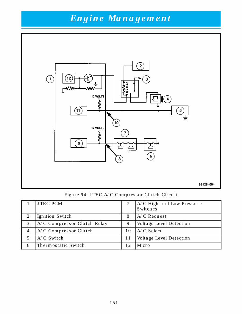
Engine Management
151
99128–094
ÁÁÁÁ
10
ÁÁÁÁ
1
ÁÁÁÁ
2
ÁÁÁÁ
3
ÁÁÁÁÁÁ
4
ÁÁÁÁÁÁ
5
ÁÁÁÁ
6
ÁÁÁÁÁÁ
7ÁÁÁÁÁÁ
9
ÁÁÁÁ
11
ÁÁÁÁÁÁ
12
ÁÁÁÁÁÁ
8
Figure 94 JTEC A/C Compressor Clutch Circuit
1 JTEC PCM 7 A/C High and Low PressureSwitches
2 Ignition Switch 8 A/C Request
3 A/C Compressor Clutch Relay 9 Voltage Level Detection
4 A/C Compressor Clutch 10 A/C Select
5 A/C Switch 11 Voltage Level Detection
6 Thermostatic Switch 12 Micro

Engine Management
152
NOTES: