Applications Project Hybrid Vehicle Turbine Engine …/67531/metadc689896/m2/1/high... ·...
32
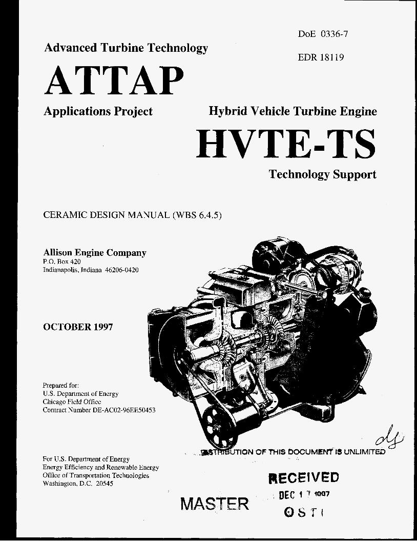
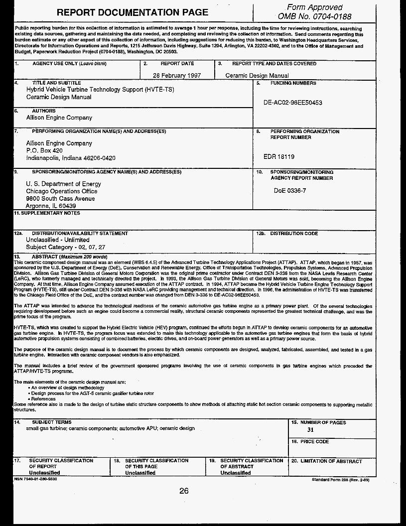
DOE 0336-7 Advanced Turbine Technology ATTAP EDR 18119 Applications Project Hybrid Vehicle Turbine Engine HVTE-TS Technology Support CERAMIC DESIGN MANUAL (WBS 6.4.5) Allison Engine Company P.O. Box 420 Indianapolis, Indiana 46206-0420 OCTOBER 1997 Prepared for: U.S. Department of Energy Chicago Field Office Contract Number DE-AC02-96EE50453 For U.S. Department of Energy Energy Efficiency and Renewable Energy Office of Transportation Technologies Washington, D.C. 20545 RECEIVED
-
Upload
duongnguyet -
Category
Documents
-
view
217 -
download
0
Transcript of Applications Project Hybrid Vehicle Turbine Engine …/67531/metadc689896/m2/1/high... ·...
DOE 0336-7 Advanced Turbine Technology
ATTAP EDR 18119
Applications Project Hybrid Vehicle Turbine Engine
HVTE-TS Technology Support
CERAMIC DESIGN MANUAL (WBS 6.4.5)
Allison Engine Company P.O. Box 420 Indianapolis, Indiana 46206-0420
OCTOBER 1997
Prepared for: U.S. Department of Energy Chicago Field Office Contract Number DE-AC02-96EE50453
For U.S. Department of Energy Energy Efficiency and Renewable Energy Office of Transportation Technologies Washington, D.C. 20545 RECEIVED

DISCLAIMER
Portions of this document may be illegible electronic image products. Images are produced from the best available original document.
NOTICE
This report was prepared to document work sponsored by the United States Government. Neither the United States nor its agent, the United States Department of Energy, nor any Federal employees, nor any of the contraCtors, subcontractors, or their employees makes any warranty, express or implied, or assumes any legal liability of responsibility for the accuracy, completeness, or usefulness of any ~ o r m a t i 0 4 apparatus, product, or process disclosed, or represents that its use would not infringe privately owned rights.
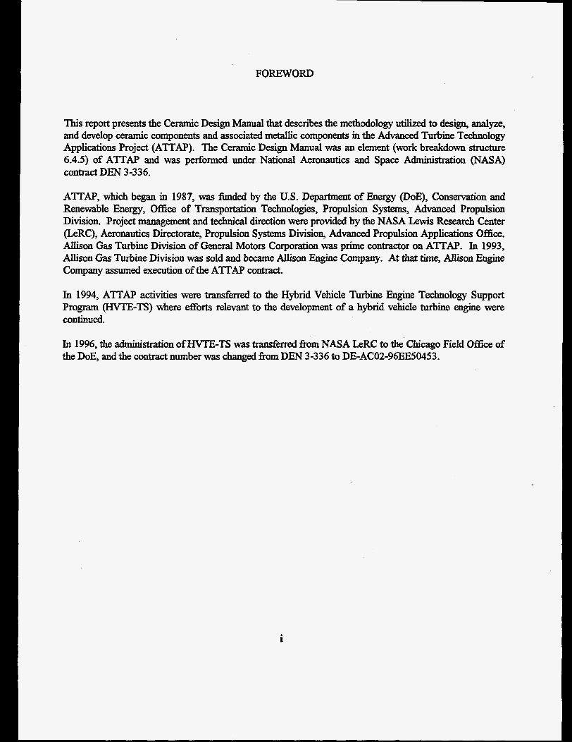
FOREWORD
This report presents the Ceramic Design Manual that describes the methodology utilized to design, analyze, and develop ceramic components and associated metallic components in the Advanced Turbine Technology Applications Project (ATTAP). The Ceramic Design Manual was an element (work breakdown structure 6.4.5) of ATTAP and was performed under National Aeronautics and Space Administration (NASA) contract DEN 3-336.
ATT'AP, which began in 1987, was funded by the U.S. Department of Energy (DOE), Conservation and Renewable Energy, Office of Transportation Technologies, Propulsion Systems, Advanced Propulsion Division. Project management and technical direction were provided by the NASA Lewis Research Center (LeRC), Aeronautics Directorate, Propulsion Systems Division, Advanced Propulsion Applications Office. Allison Gas Turbine Division of General Motors Corporation was prime contractor on ATTAP. In 1993, Auison Gas Turbine Division was sold and became Allison Engine Company. At that time, Allison Engine Company assumed execution of the ATI'AP contract.
In 1994, ATI'AP activities were transferred to the Hybrid Vehicle Turbine Engine Technology Support Program (HVTE-TS) where efforts relevant to the development of a hybrid vehicle turbine engine were continued.
In 1996, the administration of H"E-TS was transferred fiom NASA LeRC to the Chicago Field Office of the DOE, and the contract number was changed from DEN 3-336 to DE-AC02-96EE50453.
i
TABLE OF CONTENTS
Title Page
Foreword ............................................................................................................................. .i
.. Table of Contents ................................................................................................................ u
List of Table and Illustrations.. .......................................................................................... .iv
Introduction ......................................................................................................................... 1 Background. ............................................................................................................... 1 Overview of Design Methodology .............................................................................. .3
Design Process for AGT-5 Gasifier Turbine Rotor .............................................................. .6 Design Requirements ................................................................................................. .6
Operating Conditions - Duty Cycle(s) .................................................................. .6 Functional Requirements ...................................................................................... 6 Reliability Goal ................................................................................................... .7 Life Resuirern ent .................................................................................................. 7 Envelope ConstraintS - Assembly Requirements ................................................... .7 cost .................................................................................................................... .7 Fabrication Considerations ....................................................................................
Conceptual Design ...................................................................................................... 9 Prelirmnary Contiguration ..................................................................................... Material Selection .............................................................................................. 10 Method of Fabrication ........................................................................................ 10
Attachment Scheme ........................................................................................... .13 Machining Requirements
Joining to Metal Components Design Analysis ........................................................................................................ 13
Operating Conditions Thermal Mechanical Aerodynamic Loads
Probability of Survivd Material Data Base
SatisfL Requirements-Analysis Results Iteration with Supplying Vendor@) and Machining Vendor(s) to Insure Success Define Proof Test(s) Prepare DrawingsLayout Establish Build/Operating C l e a r a ~ ~ ~ Final Assembly Layout Assembly Procedure
Final D ~ i g n ............................................................................................................. 16
.. 11
Part Fabrication ........................................................................................................ 19 Part Definition Drawings Data Transfer
Tooling - Consultation with Vendor as Required Schedule Design Revisions to Address Fabrication Issues Inspection
Proof Test by/& Vendor Material Certification
How to Handle Deviations
Part Characterization ................................................................................................ 20 Inspection
Dimensional Visual-FPI-X-ray4ther NDE Material Certification Repair-Rework-- Treat
In-House Proof Tests Marking Part Numbers/Serial Numbers-Storing-Photograph Parts
Test..........................................................................................................................20 Assembly
Test Plan(s) Revise Assembly Procedure(s)
Instrummtation Proof Tests Perfonnance Test ReliabilityDurability Test(s) Rig Sub Assembly Tests Full Engine Tests
Post Test Evaluation ................................................................................................. 21 Evaluation of Test Results Part Inspection Review with Vendor Failure Analysis
Material Defect Overload Sequence of Failure Stress at Failure Origin
Design Revisions
References ........................................................................................................................ .22 Appendix A (Glossary/Abbreviation/Acronyms List) ........................................................ A-1
... Ill
LIST OF TABLES AND ILLUSTRATIONS
Table 1 Properties of structural ceramic materials ..................................................... 12
Figure 1 Ceramic component probabilistic design methodology ..................................... 5
Figure 2 Ceramic scroll flange design modificaton ..................................................... 11
Figure 3 Turbine rotor to shaft shrink fit attachment ................................................... 14
Figure 4 Cross-key attachment system provides centering without radial constraint ..... 15
Figure 5 Calculated thermal gradients for transient acceleration condition ................... 17
Figure 6 3-D calculated maximum principal stresses in turbine rotor for transient acceleration con&Oon .................................................................................. -18 ..
Figure 7 3-D calculated maximum principal stresses in turbine rotor blade for transient acceleration condition . This figure shows opposite side of blade shown in Figure 6 ......................................................................................... 18
iv
INTRODUCTION
This ceramic component design manual was an element (WBS 6.4.5) of the Advanced Turbine Technology Applications Project (ATTAP). ATTAP, which began in 1987, was sponsored by the U.S. Department of Energy (DOE), Conservation and Renewable Energy, Office of Transportation Technologies, Propulsion Systems, Advand Propulsion Division. Allison Gas Turbine Division of General Motors Corporation was the original prime contractor under Contract DEN 3-336 fiom the NASA Lewis Research Center (LeRC), who formerly managed and technically directed the project. In 1993, the Allison Gas Turbine Division of General Motors was sold, becoming the Allison Engine Company. At that time, Allison Fmgine Company assumed execution of the AlTAP contract. In 1994, ATTAP became the Hybrid Vehicle Turbine Engine Technology Support Program (HVTE-TS), sti l l under Contract DEN 3-336 with NASA LeRC providing management and technical direction. In 1996, the admidmh 'on of HVTE-TS was transferred to the Chicago Field Office of the DOE, and the contract number was changed from DEN 3-336 to DE-ACO2-96EE50453.
The A'ITAP was intended to advance the techuological readiness of the ceramic automotive gas turbine engine as a primary power plant. Of the several technologies requiring development before such an engine could become a commercial reality, structural ceramic components represented the greatest technical challenge, and was the prime h u s of the program.
The ATTAP aimed at developing and demonsbating such ceramic components that have potential for: 1) Competitive automotive engine life cycle cost, and 2) Operating for 3500 hours in a turbine engine environment at temperatures
up to 1371O C (2500O F).
HVTE-TS, which was created to support the Hybrid Electric Vehicle (HEW program, continued the efforts begun in ATTAP to develop ceramic components for an automotive gas turbine engine. In KVTE-TS, the program focus was extended to make this technology applicable to the automotive gas turbine engines that form the basis of hybrid automotive propulsion systems consisting of combined batteries, electric drives, and on-board power generators as well as a primary power source.
BACKGROUND
There is a background of over 25 years of R&D of ceramics in gas turbines. The foIlowing paragraphs summarize this history as it led to the current HVTE-TS program. Successll short- term operation of engines with ceramic components-combustors, vanes, blades, rotors, and various other components-has been demonstrated. Sophisticated analysis methods have been coupled with statistical c w r i - zation of material properties for a probabilistic approach in the design of these ceramic components.
Structural ceramics o a r the potential for significant improvement in gas turbine engine
performance. The US. Government, through various agencies, has provided funding/support to pursue this potmtd. For defense related uses, the funding agency for many projects has been the Defense Advanced Research Projects Agency @ r n A ) .
The Small Engine Components Technology Studies' (SECTS) show that the use of ceramics holds more promise than any other single technology improvement. This project, and most others in the Gas Turbine Development Area, was initially directed by NASA Lewis Research Center.
1
One of the earliest applications of ceramics was to a portable 10 kW power pack for the Army, which used a Solar Gemini turbine. In the Gemini, which is a non-recuperated engine, the use of ceramic components allow turbine inIet temperature to be raised approximately 200" C with an attendant reduction in he1 consumption (8%) and engine specific weight (35%)23.
The Army Materials and Mechanics Research Center (AMMRC) supported an extensive effort between 1972 and 1976 on Brittle Materials (Ceramic) Design, High-Temperature Gas Turbine, in which Ford Motor Company and Westinghouse Electric Company were the principal contractors a. ws program provided an important initial impetus for many later projects even though it terminated prematurely.
The Electric Power Research Institute (EPIU) subsequently funded the development of a rotor blade for large industrial gas turbines6.
The US. Navy supported a demomtration of ceramic engine components on a Garrett Axial Flow Turbine Engine of 533 kW (715 Turbine inlet temperature was raised 200' Cy producing 30% more power with 7% improve- ment in SFC.
Serious work on the application of ceramics to civil transportation engines began in 1976 with a Heavy Duty Gas Turbine Engine (HDGTE) study followed in 1978 by the Ceramic Application in Turbine Engines (CATE) program.' These programs were fimded by the DOE Conservation and Renewable Energy, Office of Vehicle and Engine R&D, and administered by NASA Lewis Research Center. Allison Gas Turbine Division, GMC, was the main contractor. Other participants included Carbomdum, Coming, GTE, Pure Carbon, and Norton.
The CATE program accomplished 9398 hours of ceramic component testing at turbine inlet temperatures of 1038' C (7814 hours) and 1132" C (1584 hours). The project demonstrated successll short-term application of a range of
ceramic components from rotor blades to supporting rings, but was curtailed by budgetary cuts, and there was no testing at the planned target temperature of 1240" C.
In 1977, the DOE Division of Energy Technology, Fossil Energy Supply R&D, iuitiated a Ceramics Technology Readiness Development (CTRD) program with We&ghouseg aimed at the possible application of ceramics in large utility combined cycle power units. The planning phase was completed in 1979, but subsequent phases were not fimded.
The U.S. Government has also provided sub- stantial direct support for the development of ceramic materials and component fabrication methods. Much of this work has been directed by Oak Ridge National Laboratory (ORNL).
Important recent engine development programs for non-military use were sponsored by the DOE Office of Transportation Systems. These were the Advanced Gas Turbine (AGT)'''l program, 1979 to 1987, and the Advanced Turbine Technology Application Project (ATTAP) which followed it. The AGT program was aimed at development of a 75kW (100 HP) automotive gas turbine engine with 30% greater efficiency than that of a gasoline engine and a capability of using a wider range of fuels with reduced emissions. Ceramic components which were designed, fabricated, and tested, included combustors, radial inflow turbine rotors, vanes, scrolls, regenerators, and other associated parts. The ATTAP project was concerned with advancing ceramics technology, especially improving reliability and durability. The prime contractors in the AGT and ATI'AP programs were Allison Gas Turbine Division of General Motors Corporation and Garrett Auxiliary Power Division of AlliedSgnal Aerospace Company. In the Allison Gas Turbine Division ATTAP'* program, an automotive gas turbine engine merent from that utilized in the AGT program was utilized as a test bed to develop ceramic hot section components. That engine, which incorporated axial flow turbine stages, was rated at about 150kW (200HP) at 1371" C (2500" F)
2
turbine inlet temperature. The Garrett Auxiliary Power Division ATTAP13 program initially utilized the engine developed in their AGT program for continued ceramic component development, but later changed to a production based engine as a test bed for ceramic component development. The engines utilized in both AGT programs and in the Allison ATTAP program were designed to be primary power sources for an automobile. The AGT and A'ITAP programs were managed by NASA LeRC.
AGT and ATI'AP included substantial subcontract development activities at the major domestic suppliers of ceramic components. The ongoing materials development and design programs coordinated by ORNL were also closely involved in the overall effort.
In 1994, the AlliedSignal A"AP program became the Ceramic Turbine Engine Demonstration Project14 and Contirmed development of ceramic components in the production based turbine engine APU being utilized at the end of the AITAP effort,
Also, in 1994, the Allison A'ITAP program became the Hybrid Vehicle Turbine Engine Technology Support (HVTE-TS)" program where ceramic component development continued in the turbine engine utilized in A'ITAP as well as a turbine engine APU being developed in support of the hybrid vehicle programs. Technical direction and management of HVTE- TS was transferred to the Washington, D.C. office of the DOE in 1996. HVTE-TS contract administration was transferred to the Chicago Field Office of the DOE at the same time.
OVERVIEW OF DESIGN METHODOLOGY
The inherent characteristics of ceramic materials di&r f ic ien t ly fiom metallic structural materials to require special attention at d phases of the design effort. In most cases, specifically different practices are necessary.
The need for change in design practice is not a new phenomenon to gas turbine engine experience. Materials use has continually progressed to lower ductility levels through the incorporation of high-strength steel alloys, super-
necessary changes in design methodology have addressed refined criteria definitions, improved fatigue characterization through finite element modeling and combined loading conditions, use of fracture mechanics technology, and appli- cation of probabilityireliability practices. The advent of structural ceraniic materials, therefore, represents a logical extension of these changes in the design disciplines required for gas turbine components.
alloy~, and high-~&@ tiem. The
Probabilistic (as opposed to detemhistic) design analysis is required for each ceramic turbine component. Finite element models, either two or three dimensional, are generally required to adequately calculate the temperature andstress distributions necessary for assessing component reliability (probability of survival) at critical operating conditions. In the Allison A'ITAP progam, the engine utilized as a test bed for ceramic component development was designed to be a primary p e r source for an automobile. A primary power source must operate over a broad range of power settings and have a very rapid response to changes in power level. Normally, for this type of engine, the critical operating condition occurs during rapid transient engine operatioq either an acceleration fiom low to high power or a rapid shutdown fiom high to low power. Thermal stresses, due to temperature gradients within the components, are most severe during this period. Input data fbr this analysis is derived from the engiue duty cycle, material characteristics, reIiability requirements, and proof-test definition.
In the HVTE-TS program, the emphasis changed fiom an engine designed to be a primary power source to that of an auxiliary power source (turbine APU) working in combination with a battery pack to provide power for a hybrid electric vehicle. The transient operating conditions (rate of change in power level) of a
turbine APU likely will be less severe than those of a primary power source engine. Also, a turbine APU will normally operate over a narrow power band with most operation at or near full power. Hence, the operating condition(s) for which the ceramic components have the least probability of survival in the APU application may not be a transient condition but instead a steady state condition. This can be determined only after the duty cycle of the engine is defined.
All hot section components in an APU engine application generally should have a less severe “ride” than those in a primary power source engine application. The design analysis and discussion presented in this design manual pertain to the work done in ATTAP fbr an engine designed for a primary power source application.
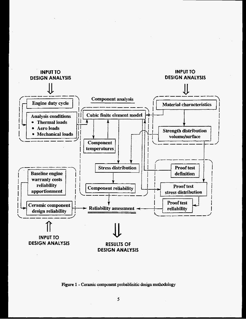
A schematic diagram of the ceramic component design/analysis process is shown in Figure 1. Thermal, aerodynamic, and mechanical loads for steady-state and transient operation in both rig and engine environments must be considered. Proof-test requirements are determined for each component. Proof-test failures can be predicted and correlated with component operational reliabihty. The material properties necessary for these analyses are continually updated through material testing. Also, component data obtained from rig and engine tests can be fed back through the analytic models for correlation of the analytic techniques. This feedback provides improved analytic predictive capability for evaluation of subsequent geometric co&gurations andor the impact of cbanges in environmental conditions.
I
4
INPUT TO DESIGN ANALYSIS
INPUT TO DESIGN ANALYSIS
f \ Component analysis --------
Engineduty cycle 1 --------- If I Analysis conditions ' I 1 I Thermal loads I Aeroloads
1 - 1 I f
Cubic finite element model
r 1 I T
I
\ i I
I I
A_-------
f- I Material characteristics I 1 1
v I I 1 1 Strength distribution
i volumdsurface I
I I /-------- ; \ I
l i I 1 warranty costs
reliability Proof test stress distribution
Proof test
1 i9-1: design reliability =I Reliability assessment \--- ---- - 1
INPUT TO DESIGN ANALYSIS RESULTS OF
DESIGN ANALYSIS
Figure 1 - Ceramic component probabhitic design methodology
5
DESIGN PROCESS FOR AGT-5 GASIFIER TURBINE ROTOR
This section of the design manual will detail the design process for monolithic ceramics using the integrally cast bladdwheel AGT-5 wilier turbine rotor as an example. The description will include the fhbridon, characklization, and testing phases of the rotor development, because they impact the design process. The design process for other ceramic engine hot section components (combustor, static turbine nozzle or vortex, etc.) is similar to that of the turbine rotor. The major dif5erence to be considered is the method of attachment of the ceramic components to the associated (metallic) engine structure. Typically, that aspect of the design for static components is more difficult because of the relative thermal growth between the ceramic and metallic components.
DESIGN REQUIREMENTS
Having made a decision to utilize a ceramic component(s) in an engine, the development of design requirements and a conceptual design are two of the initial efkrts to be undertaken. As noted above, ceramic component design entails a considerable amount of detailed analysis to ensure success. To complete a thorough design and analysis of a ceramic component, detailed design requirements must be established.
Design requirements include:
a
a
efficiency gods emissions goals operating conditions - duty cycle(s) functional requirements reliability goals life requirement envelope constraints-assembly requirements cost fabrication considerations
OPERATING CONDITIONS
In the context of ceramic design methodology, operating conditions are those which define worst case conditions to which the component might be exposed in service. The maximum power engine cycle is one such condition to be considered. Transient operating conditions, such as a cold start-up to max power or a rapid reduction in power, are examples of other conditions to be considered. In real life service, an automotive engine might be started and accelerated to high
power in a few seconds in an emergency or at the whim of an aggressive driver. In ATI’AP, analysis showed that for the regenerative automotive engine, rapid deceleration was not as severe as a cold start-up because of the heat stored in the regenerator(s). In a nonregenerative turbine engine, a rapid reduction in power might produce very high stresses in hot section components. A thorough understan- of the conditions (including time at condition) under which the engine and ceramic components will operate in service is necessary so that appropriate “designyy operating conditions can be defined for analysis purposes.
For ATIAP, the turbine rotor components were analyzed for cold spin conditions (proof test), max power steady-state, and a very rapid cold start fiom idle to max power transient. The latter condition resulted in the lowest probability of survival for the turbine rotor.
FUNCTIONAL REQUIREMENTS
The functional requirements of the various engine components are, of course, varied. In the hot section, the combustor assembly contains and directs the hot combustion products to the turbine nozzle that accelerates and directs the hot gases to the turbine rotor. The gases expand through the turbine rotor blades to produce torque. The turbine blades --exert force on the turbine rotor disk to produce torque at the rotor hub and a comection must be made between the rotor hub and a shaft or other driven component. The bladdrotor disk interface also must react the centrifbgal load of the blade on the rotor disk.
6
The static turbine structure must precisely locate the blade tip shroud with respect to the rotating blades to maintain close operating clearances while preventing interference.
RELIABILITYGOAL
The overall engine specification establishes the reliability goal for the complete engine assembly. In ATI’AP, that goal was that three of four engines would reach 100,000 miles (3500 hours) without a major engine Wure. To determine the reliability goal(s) for the ceramic components, the engine assembly was examined to determine the total number of Mure sites for all components (metal and ceramic). For the ATTN test bed engine (AGT-S), that total was about 500 sites. Thus, the design probability of survival @OS) for each fdure site was (.75)”500 =.999425. If a turbine rotor with 20 blades contained 42 failure sites, its overall required POS would be (.999425)42 = .97612. This POS was the goal of the gasifier turbine rotor in the A’ITAP program. Since the analysis utilized was for fast fracture, it is implied that the component could fail at first start-up at the same rate. Clearly this is not acceptable. However, actual assembly line reliability requirements are closely held data and not available to this program. The design POS of a component can be significantly enhanced by utilizing an appropriate proof test during component I l E U I U f k t U ~ .
The life requirements are closely related to the reliability goals. For ATTAP, the engine life requirement was 3500 hours total of 3ypical automotive” use. It is estimated that the engine would operate at full power for only 100 hours, generally for periods of only several seconds at a time. An exception might be pulling a trailer up a long grade. A heavyduty truck or industrial engine would have a more severe duty cycle.
Life requirements will impact material selection andor allowable operating stresses if operation
at high power is for extended times. It is not a major consideration, however, for a typical automotive engine.
0 ENVELOPE CONSTRAINTS/ ASSEMBLY RJEQUIREMENTS
The introduction of ceramic hot section components into turbine engines has generally involved retrofitting components into existing engine designs with as little redesign of associated metallic components as possible. It was recognized in ATTAP that consideration had to be given the brittle nature of ceramic materials along with the fact that when ceramic materials were substituted for sheet steel, the material thichess increased %%om 0.5 to 2.0 mm for metallic components to 2.0 to 4.0 mm for ceramic components. The brittleness of ceramic materials is of concern mostly in airfoil design where the blades must be thickened to obtain resistance to foreign object damage. The impact of increased size blading becomes apparent when conceptual designs are prepared. The design should allow for easy assembly to avoid impact damage to the ceramic parts. The rotor design should not require disassembly following balance to maintain the best possible balance going into the engine.
0 COST
In the automotive engine application, cost is a very important factor in the desigdaccqtability of a component. Thus, the parts must be kept simple and where possible, small. In heavyduty and in- applications, cost may not be a major factor in the desigdsuccess of a ceramic component. Larger engines may utilize separate bladelwheel assemblies, whereas the small automotive engine will almost certainly utilize the lower cost integrally cast bWwhee1 component. Physical size of ceramic components is a major driver in cost, hence, an assembly of several small components may be less expensive than a one-piece component which serves the same function.
FABRICATION CONSIDERATIONS
The method(s) of component f%brication must be considered during the design process, because it may effect: (1) the material characteristics (strength, etc.); (2) the configuration of the part (volume or shape, minimum or maximum material thickness); (3) the dimensional accuracy of the part, an& (4) the amount of finish machining required.
Additionally, advanced planning with the vendor@) should be undertaken because the method (process) utilized to produce small quantities of a developmental part may be vastly diEerent fiom that required to manufkcture production quantities of the component in a cost- effective manner.
The importance of coordination with the ceramic vendor during the desigddevelopment process m o t be overstated.
CONCEPTUAL DESIGN
PRELIMINARY CONFIGURATION
Prelimitmy designs of ceramic engine com- ponents should reflect special considerations given to the designs because of the brittle nature of the ceramic materials. Early recognition of detail features which tend to decrease probability of suMval of ceramic components, will speed the design process and may save a major revision during the iiml design process to rectify a design deficiency.
When beginnins the design of a ceramic turbine rotor blade (either integral with a ceramic rotor disk or individually mounted in a metallic wheel), consideration must be given to insure adequate resistance to foreign object damage (FOD). Ceramic blades with good FOD resistance typically have larger cross sections (increased leading and trailing edge radii) than their metallic countexparts. To maintain proper aerodynamic design parameters (blockage, etc.), the more robust ceramic blade will have increased chord length and be f’ewer in number when compared to metallic blades. This requires increased axial length for the rotor with ceramic blades. Similar consideration must be given ceramic stator vane rows. Failure to provide adequate axial length for the ceramic turbine blade rows in preliminary designs will result in a major revision later on. Aerodynamic performance losses will occur if blade design parameters are adversely impacted (example, increased blockage) late in the turbine development program. Excess robustness in rotor blades, on the other hand, increases the load on the turbine rotor, requiring greater rotor thickness and increased thermally induced stresses during transient operation, and an overall loss in engine performance. Allison’s test experience with axial turbine rotors indicates that a minimum trailing edge thickness constraint of 0.50mm should be used in the aerodynamic design of all &ods to &ow adequate FOD resistance.
If the turbine design suggests the use of an integral bWwhee1 component, consideration must be given to the design of the rotor to shaft attachment. Typical joints are either shrink fit or brazed with the metallic shaft surrounding the ceramic rotor stub shaft. The sbaft/rotor attachment maximum operating temperature must be limited to a level which will insure adequate grip [usually around 538’ C (lOOOo F)] while, at the same time, it is desirable to maintain the rotor disk at as bigh a temperature as possible to reduce radial thermal stresses.
Another consideration to be given while developing a preliminary design of a turbine rotor assembly utilizing a monolithic ceramic rotor is whether the rotor disk has a center hole or not. Rotor assembly procedure may be enhanced if the disk has a bored out center. Conversely, if a satisfactory rotor design cannot be developed with a center bore, the method of rotor assembly may be more restricted and thus affect the overall turbine design.
In may instances, ceramic components will be designed for retrofit into existing engine assemblies. Ceramic components have several characteristics which differ fiom metallic components which must be mnsidered in the prelimbuy design phase. One is wall thickness, usually 2.0 to 4.0 mm for ceramic components versus 0.5 to 2.0 mm for sheet metal components. This often requires additional space. The low thermal expansion characteristic of ceramic materials requires additional sophisti- cation in the ceramidmebl attadment points to eliminate straining the ceramic component (see “Attachment Scheme” section). Such joints usually require a larger space claim than joints between similar metallic components.
Continuous loop radial flanges should be avoided on ceramic components, because they typically experience a radial thermal gradient which will induce stress and lower POS. Thermal gmdtents, in general, are detrimental to ceramic components, and where severe gradients are expected, the part should be segmented into multiple pieces to relieve thermal strain. The example, shown in Figure 2, is a design which was modified to eliminate thermal stresses in a ceramic s c d flange by making the flange a separate piece. The key to a successfid design of a ceramic component is to minimize imposing strain on the part by minimizing thermal gradients and avoiding mechanical constraint.
MATERIAL SELECTION
The material selection process for structural ceramic components involves consideration of a variety of material characteristics. Most obvious are strength and maximum operating temperature capability. Other characteristics that are also important to varying degrees include thermal conductivity, specific heat, Young’s modulus, coefficient of thermal expansion, thermal shock resistance, toughness, method of fabrication, and cost.
Most ceramic component development activities during AGT and A7TAP centered around high- strena structural ceramics, namely, vendor specific silicon nitrides and silicon carbides. An exception is the low-strength ultra-low-expansion materials suitable for the regenerator disk@) utilized in the automotive turbine engine. Development materials with moderate strength capabilities may be suitable for certain ceramic components such as combustor bodies, turbine scroUs, rotor blade tip shrouds, and transition ducts. Materials are continuously being improved and new materials and methods of fabrication are being introduced periodically.
Table 1, showing typical material properties for structural ceramics developed for turbine use in the ATTAP program and reference metals, may be used as a guide for &rial selection during the conceptual design phase. For the turbine
rotor, high strength with adequate operating temperature capability are major characteristics of interest. However, since thermal gmbents, severe during transients, exist in the rotor and attachment shaft, Young’s modulus e), coefficient of thermal expansion (m), and t h e d conductivity, has a major impact on the stress developed by the thermal gradient. The relatively high (E) and (oc) of silicon carbide put that class of materials at a disadvantage when compared to the silicon nitrides. However, for lower stress applications, silicon carbide has a higher operating temperature Iimit.
Capability of the ceramic vendor to fabricate parts at an acceptable cost also has a major impact on material selection. Much effort is required in this aspect of ceramic component development.
METHOD OF FABRICATION
Fabrication of high strength ceramic components will be a major issue in the development of low cost structural ceramic components. Drain casting, slip casting, gel casting, injection molding, cold isopressing, pressure drain slip casting, and other proprietary fabrication methods have been utilized in the fabrication of ceramic components for AGT and A’ITAP. The method of f8bricati04 peculiar to many material systems, has a major impact on component design. Constant interaction with the ceramic vendor is necessary during the design process to insure that the part can be produced as designed. For the turbine rotor, toding of one Variety or another is required to accurately produce the blade shape. Blade design must allow remod of the tooling which forms the blade detail. The rotor disk may be formed net shape or with machining stock as required. “Mold lock” must also be considered when designing components fabricated in hard tooling.
Parts with machined surfaces typically will have higher strengths on those surhces as compared to that on ascast surf8ces, however, mac-
10
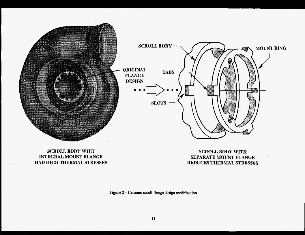
SCROLL BODY WITH INTEGRAL MOUNT FLANGE
HAD HIGH THERMAL STRESSES
Figure 2 - Ceramic scroll flange design modification
1 1
RING
SCROLL BODY WITH SEPARATE MOUNT FLANGE
REDUCES THERMAL STRESSES
ceramic materials is costly. Every effort should be made to minimize machining on the component. This impacts rotor design as well as other structural ceramic component assemblies.
ATTACHMENT SCHEME
Ceramic turbine rotors typically are joined to metallic shafts to allow connection to components driven by the turbine. The joint must transmit the drive torque at the design operating temperature, or conversely, the design must limit the operating temperature of the joint to that which it is capable of withstanding. Current joint technology, shrink fit or brazing, allows operating temperatures of 538 to 593' C (1000 to 1100O F). An example of a shrink fit joint is shown in Figure 3. A compliant layer between the metal and the ceramic will usually result in a more reliable assembly by decreasing peak stresses in the ceramic.
Static ceramic components must be assembled to other ceramic components or to metallic engine structures. The relative rates of thermal expansion of various ceramic and metallic materials dictate that special consideration be given to joint design. The designs must allow free movement of the components relative to each other so that no mechanical strain is imposed on the ceramic components. One design approach is the cross-key configuration, shown in Figure 4, which centers the ceramic component with respect to the metal piece without co- g either piece radially. Another requirement of ceramic-to-metal joints is thermal isolation of the two components, both to reduce thermal stress in the ceramic component and oxidation of the
machining is metallic component. Muurmzed another major consideration in ceramic component joint design.
. . .
DESIGN ANALYSIS
of the design effort. Probabilistic analysis is utilized for each ceramic turbine component. Finite element models, two or three dimensional (in the case of a turbine rotor design, both) are generally required to adequately calculate the temperature, deflection, and stress distribution necessary for assessing component reliability. Analyses are conducted at operating conditions considered to be most severe for each component. In the primary power source engine utilized in AnAP, the minimum calculated probability of suMval for ceramic components usually occurred during a severe start-up to max power transient. The probability of survival was calculated based on Weibull's weakest-link theory as described in reference 16. An analysis program, such as CARES described in reference 17, can also be utilized to determine the probability of survival for the ceramic components. For the anaIysis, input data is derived from the engine duty cycle, material characteristics, reliability requirements, and proof test definition. First, the operating temperature distribution in the ceramic component is calculated. Inputs for this portion of the design analysis include accurate definition of the component shape, complete thermal boundary conditions to describe the thermal environment of the component, and the physical heat transfer characteristics of the ceramic material. Heat transfkr calculations are made for all operating conditions to be analyzed including many snapshots in time during transient operatingmodes. Theresults areexaminedto discover conditions of most severe thermal gradient in the component or different portions of the component. In the case of the turbine rotor, during an acceleration, the most severe transient thermal gradient occurs earlier in the blades than in the rim or hub of the rotor because the low mass blade responds to a change in gas temperature much more rapidly than does the rotor disk.
The inherent characteristics of ceramic materials are sufficiently Merent from metallic structural materials to require special attention at all phases
Predicted operating temperatures of such details as rotorhhaft attachments are also reviewed to determine if the absolute temperatures and @enb are acceptable. Ifunacceptable, the
13
METAL SHAFI'
SHRINK FIT JOINT WITH
A SHRINK FIT JOINT KEEPS THE CERAMIC IN COMPRESSION AND TRANSMITS TORQUE FROM THE CERAMIC TURBINE ROTOR TO THE METAL SHAFT
Figure 3 - Turbine rotor to shaft shrink fit attachment
14
CROSS-KEY ATTACHMENT /- CERAMIC \ PART
Figure 4 - Cross-key attachment system provides centering without radial constraint
15
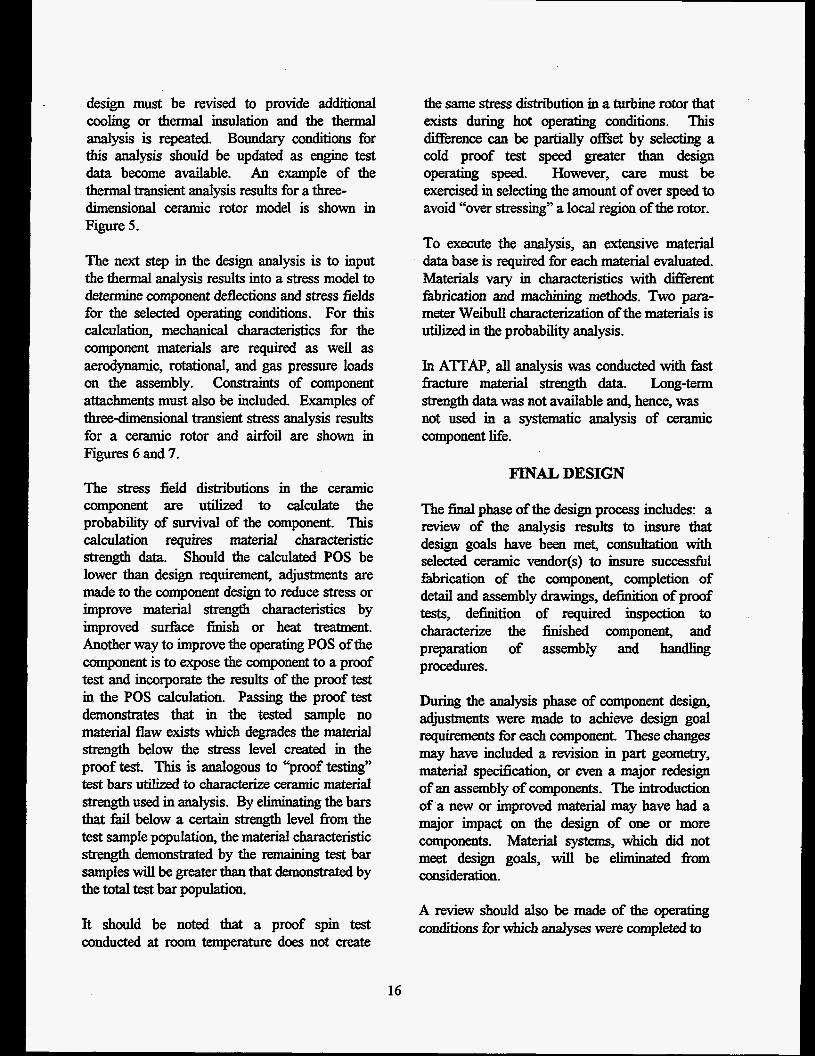
design must be revised to provide additional cooling or thermal insulation and the thermal analysis is repeated. Boundary conditions for this analysis should be updated as engine test data become available. An example of the thermal transient analysis results for a three- dimensional ceramic rotor model is shown in Figure 5.
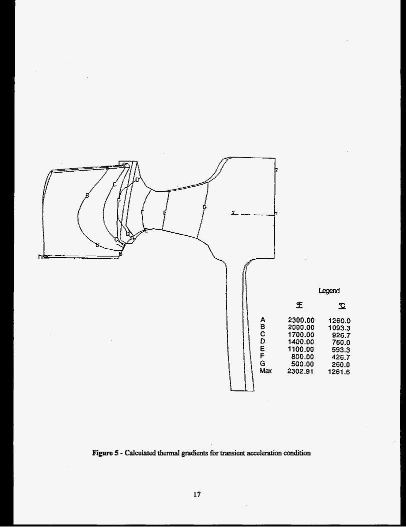
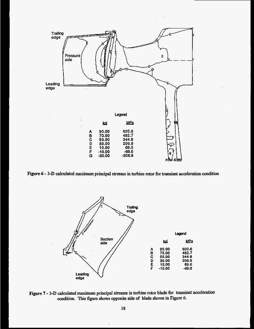
The next step in the design analysis is to input the thermal analysis results into a stress model to determine component deflections and stress fields for the selected operating conditions. For this calculation, mechanical characteristics for the component materials are required as well as aerodpamic, rotational, and gas pressure loads on the assembly. Constraints of component attachments must also be included. Examples of three-dimensional transient stress analysis results for a ceramic rotor and airfoil are shown in Figures 6 and 7.
The stress field distributions in the ceramic component are utilized to calculate the probability of suMval of the component. This calculation requires m a t e d characteristic strength data. Should the calculated POS be lower than design requirement, adjustments are made to the component design to reduce stress or improve material strength c-ristics by improved surface finish or heat treatment. Another way to improve the operating POS of the component is to expose the component to a proof test and incorporate the results of the proof test in the POS calculation. Passing the proof test demonstrates that in the tested sample no material flaw exists which degrades the material strength below the stress level created in the proof test. This is analogous to “‘proof testing” test bars utilized to chasacterize ceramic material strength used in analysis. By eliminating the bars that fkd below a certain strength level fn>m the test sample population, the material characteristic strength demonsbated by the remaining test bar samples will be greater than that demomtrated by the total test bar population.
It should be noted that a proof spin test conducted at room temperature does not create
16
the same stress distribution in a turbine rotor that exists during hot operating conditions. This Merence can be partially o&et by selecting a cold proof test speed greater than design operating speed. However, care must be exercised in selecting the amount of over speed to avoid “over stressing” a local region of the rotor.
To execute the analysis, an extensive material data base is required for each material e v a l d . Materials vary in characteristics with different fhbrication and m c k g methods. Two para- meter Weibull c- * ‘on of the materials is utilized in the probability analysis.
In ATI’AP, all analysis was conducted with fast fracture material strength data. Long-tern strength data was not available and, hence, was not used in a systematic analysis of ceramic component life.
FINAL DESIGN
The final phase of the design process includes: a review of the analysis results to insure that design goals have been met, consultalion with selected ceramic vendor@) to insure successful fabrication of the component, completion of detail and assembly drawings, definition of proof tests, definition of required inspection to characterize the finished component, and preparation of assembly and handling procedures.
During the analysis phase of component design, adjustments were made to achieve design goal requirements for each component. These changes may have included a revision in part geometry, material specification, or even a major redesign of an assembly of components. The introduction of a new or improved material may have had a major impact on the design of one or more components. Material systems, which did not meet design goals, will be eliminated .from consideration.
A review should also be made of the operating conditions fbr which analyses were completed to
A 8 C D E F G Mp:
2300.00 2000.00 1700 -00 1400 -00 1 100.00 800.00 500.00
2302.91
1260.0 1093.3 926.7 760 .O 593.3 426.7 260.0
1261.6
Figure 5 - Calculated t h e d gradients for transient acceleration condition
17
A 90.00 B 70.00 C 50.00 D 30.00 E 10.00 F -10.00 G -30.00
n
620.6 482.7 344.8 206.9 69.0
-69.0 -206.9
Figure 6 - 3-D calculated maximum principal stresses in turbine rotor for transient acceleration condition
ksi A 90.00 5 70.00 C 50.00 D 30.00 E 10.00 F -10.00
Mea 620.6 482.7
206.9 69 .O -69.0
344.8
Figure 7 - 3-D calculated principal stresses in turbine rotor blade for transient acceferation condition. This figure shows opposite side of blade shown in Figure 6.
18
ascertain that the conditions utilized remain appropriate and that no new operating con- dition(s) have emerged which should be investigated.
A major part of the design process is intendion with the ceramic vendors selected to fabricate the components. Minor and major issues may arise as the component designs evolve. Issues, such as configuration, material selection, methd of fkbrication, machining, or dimensional toler- ancing, must be resolved so that changes can be made with only minor impact on schedule and cost. In A'TTAP, interaction with ceramic vendors was extensive and it had a very positive effect on the program results. How hished components are characterized, both dimensional and material evaluation, must also be agreed to before fabrication is complete. In ATI'AP, vendors who supplied turbine rotors delivered them only after they passed a cold spin proof test as defined on the design print.
Proof tests, particularly for turbine rotors, may be defined during the d y s i s phase of the design process when it becomes apparent that the design POS can only be achieved with a proof test of each component delivered. Proof testing may also become part of the in-house character- ization of finished components.
Final design (detail) and assembly drawings are prepared for each component. These drawings reflect final definition of the components and the inspection procedures to evaluate them. Dimensional tolerances, reviewed with the supplying vendor, define how part assemblies fit together. Detailed review of the thermal and stress analyses of the various components will help set critical assembly dimensions. Example: rotor blade tip to shroud clearance, so that interferences which would cause failure are avoided. Very detailed thermal and mechanical deflections are available from the analysis.
Due to their brittle nature, ceramic components are susceptible to handling damage, especially during inspection and assembly. To minimize risk during assembly, a written assembly
19
procedure should be prepared. This document should define: critical dimensions to be checked before assembly commences to prevent intefierence, the order in which parts are to be assembled, points during the assembly process where accidental damage could occur, fastener torque, and component clearances. The pro- cedure should also provide sufficient pictorial information for clariv.
PART FABRICATION
Many issues related to ceramic component fabrication will have been resolved during vendor interaction throughout the design process. Experience has shown, however, that new concerns arise during fabrication that were unforeseen. Also, an improvement or other alteration in material specification may impact the design. AU ceramic components require tooling and/or machming to complete fabrication. The type of tooling may impact the component design and revisions may be necessary to complete fabrication if difficulties are encountered with the tooling. The amount and type of machining must be defined and agreed upon, because it may impact material strength characteristics and component pefiormance. Of particular concern in ATI'AP was the conQwation of the fillet between the leading edge of the rotor blade and the rotor disk. Drawing interpretation mered from one vendor to another, and additionally, the t o o h used by the vendors had differing capabilities of producing the desired shape. In addition, vendor requirements for between blade tool inserts dif€ered with respect to draft angle. Component delivery schedule is important to overall program plans. Typical delivery time during ATI'AP was four to six months. There were instances during turbine rotor fabrication where blade deformation during manufiwtmhg was severe enough that airfoil shape did not meet design specification. This required a decision as to whether the rotors could be utilized in test while tooling was modikd to mrrect blade deformation. It is fortunate when testing can proceed by making
adjustments to accommodate parts out of specification because second generation parts will require substantial time to produce. Having alternate suppliers is one hedge against a serious program schedule slip when delivery schedules are not met. Unforeseen fabrication difficulties may require a design revision. “Mold lock” or a problem making a planned joint between ceramic subassemblies were typical problems which arose in A’ITAP. In general, ceramic-to-ceramic bonds were avoided in design because the bonding technology was not well developed, except in siliconized silicon carbide material systems. However, to simplifL fhbrication, vendors would attempt to bond simple castings to create a more complex one or to achieve a local thick section in a casting which typically would have a constant wall thichess.
Certification of material characteristics should be required with all parts shipments. The vendor should maintain records of all part lots so that processing problems can be traced in the event of material deficiency during development testing.
utilized in the design analysis. Analysis updates may be required using measured material strength characteristics if substantial deviation exists. For components too small to provide bend bars, a functional proof test should be performed to insure satisfactory performance. An example would be small aidoil blades. In this case, a hot proof test should be pexformed which duplicates as close as possible, actual operating conditions in service. A number of samples should be tested to characterize the lot of parts. Some components lend themselves to a practical static load test which will simulate engine operating conditions. Proof tests are often the only practical method of verifying ceramic component integrity prior to an engine test. Proof testing of rotating ceramic components must be accomplished on all specimens because each has its own distribution of flaws. Such flaws are difficult, of not impossible, to detect by any other method of inspection. Automated proof testing will be required in large scale production of rotating components.
Typically, in ATTAP, the vendor provided dimensional inspection fecofds for deliverable parts, and in the case of turbine rotors, certified proof spin test results were required.
Development ceramic components should be serialized and permanently marked similar to critical metallic components. This allows tracking during testing and tractability to production origin.
PART CHARACTERIZATION
It is important to fully characterize finished ceramic components before releasing them to test. Characterization includes:
Consistent deviation from design specification for a component suggests that a design revision should be considered. This requires consultation with the vendor and analysis of the revised design to insure that original design goals are met.
0 dimensional inspection visualinspection x-ray and florescent penetrate inspection flexwe testing of material cut from a sample component proof test (hot or cold)
Flexure testing of bend bars cut from finished samples of a ceramic component demonstrates whether the material meets the specification
20
TEST
Successll testing of a ceramic component certifies the accuracy of the design and the material processing during fabrication. A successful test is preceded by carehl assembly of the components being evaluated. The assembly procedure prepared during the h a l design phase should be utilized during the assembly process and revised as appropriate. Care must be
exercised during the assembly process to avoid damage to the brittle ceramic components.
Test plans should be developed to systematically evaluate the components at increasingly greater performance levels and for increasingly longer periods of time until design operating conditions are demonstrated. Initial tests may constitute a “proof’ test of an individual component or a small assembly of components. The “proofed” components are assembled together for additional testing. In Al’TAP, gasifier turbine components could be tested in rigs without risking power turbine hardware. Thus, when the components progressed through the test rigs, there was considerable confidence in the components when they were assembled into a complete engine.
Test instnunentation is essential to determining the performance of the components and to confirm the boundary conditions utilized during analysis. The d y s e s should be updated as test data is accumulated. Test instrumentation data is particularly important when evaluating test wures.
POST TEST EVALUATION
Much can be learned from post test examinafi on of the ceramic components whether intad or failed. Intact parts may reveal capability of enduring incidents thought to cause failure. Examples are survival of foreign object ingestion and blade tip-shroud rub. Excessive rub may suggest a change in build clearance is in order or that concentricity between the rotor and blade tip shroud is not being maintained. Failed ceramic components often will reveal valuable informaton in determining a failure scenario. Analysis of a fhiled ceramic component may reveal a material defect not recogwed during inspection, or an overload condition suggesting unplanned assembly stress caused by incorrect
21
assembly clearance or deformation of associated components. The progression of cracks in ceramic components can often be traced from the point of origin by carell inspection. If the fkcture origin is intact, the bdk stress of Mure can often be determined. A very low stress at the point of origiu suggests a deficiency in the material, such as a ff aw due to poorly processed material. A stress, higher than the anticipated operating stress, suggests an overload f’ailure, typically secondary, which exonerates the component as being the primary cause of failure.
The results of successll and unsuccessfi~l tests are input to the design process. Successll tests typically confirm the correctness of the boundary conditions utilized in the analytical models.
Results fiom the analysis of Wed components are reviewed to determine if model boundary conditions should be revised or if a design revision should be made to reduce stress levels and increase POS.
REFERENCES
’ M.R. Vanm, et al , “An Overview of the Small Engine Component Technology Studies,” AIAA-86-1542, American Institute of Aeronautics and Astronautics, 1986
RA. Mercure, ‘‘Small Gas Turbines for US. Army Auxiliary Power Systems,7y ASME 86-GT-282, American Society of Mechanical Engineers, 1986
J.C. Napier and J.P. Arnold, “Advancements in Application of Ceramics to the Gemini Radial Flow Gas Turbine,” ASME 85-GT-183, American Society of Mechanical Engineers, 1985
A.F. McLean, Ceramics in Small Vehicular Gas Turbines, Ceramicsfor High-Performance Applications, J. Burke, A.E. Gowan, and R.N. Katz, Ed., Brookhill Publishing, 1974, p 9-36
RJ. Bratton and A.N. Holden, Ceramics in Gas Turbines for Electric Power Generation, Ceramics for High-Performance AppIications, J. Burke, A.E. Gowan, and RN. Katz, Ed., Brookhill Publishing, 1974, p 37-60
C.A. Anderson and RJ. Bratton, et al., EPRI Ceramic Rotor Blade Program, Ceramics for High-Perjormnce Applications--mI1, ReliabiIity, E.M. h o e , RN. Katz, and J. Burke, Ed., Plenum Press, 1983, p 783-803
D.W. Richerson and K.M. Johansen, “Ceramic Gas Turbine Engine D e m o d o n , ” Final Report, Navy Contract N00024-76-C-5232, May 1982
H.E. Helms, P.W. Heitman, L.C. Lindgren, and S.R Thrasher, “Ceramic Applications in Turbine Engines,” Final Report DoE/NASA/OO 17-6, NASA-CR-1747 15, Department of Energy, National Aeronautics and Space Administration, Oct 1984
8
RJ. Bratton and K.L. Rieke, Key Ceramic Development Issues for High-Temperature Utility Turbines, Ceramics for High-Perjormance AppIications-m, ReIiabiIity, E.M. Lenoe, R.N. Katz, and J. Burke, Ed., Plenum Press, 1983, p 235-247
9
lo “Advanced Gas Turbine Technology ( A 0 Allison Gas Turbine Division, Final Report DoE/NASA 0168-1 1, NASA-CR-182127, Department of Energy, National Aeronautics and Space Administration, Aug 1988
‘‘Advanced Gas Turbine (AGT) Development Project,” Garret Auxiliary Power Division, Final Report DoE/NASN0167-12, NASA-CR-180891, Department of Energy, National Aeronautics and Space Administration, Dec 1987
l2 S.G. Berenyi, L.E. Groseclose, and S.J. Hilpisch, Advance Turbine Technology Applications (ATIAP), Proceedings of the Annual Automotive Technology Development Contractors ’ Coordination Meeting - 1993, S A E P-278, Society of Automotive Engineers, Inc., 1994, p 249-255
22
APPENDIX A GLOSSARY/ABBREVIATlONS/ACRONYMS LIST
ATTAP AMMRC AGT AGT-5 CARES CATE SIALON a CTRD DARPA " C OF DOE EPRl FPI FOD GMC GPa g/cm3 GTE HDGTE HP HIPSN HPSC HPSN HEV HVTE-TS jJs C KSI kW LeRC MPa MSI mm NASA NDE ORNL POS RBSC RBSN R+D Sic ssc SSN SECTS SFC 3-0 E Wlm K m WBS
Advanced Turbine Technology Applications Project Army Materials and Mechanics Research Center automotive gas turbine/Advanced Gas Turbine automotive gas turbine test bed Ceramics Analysis and Reliability Evaluation of Structures Ceramic Applications in Turbine Engines Ceramic Process Systems silicon nitride coefficient of thermal expansion Ceramics Technology Readiness Development Defense Advanced Research Project Agency degrees Celsius degrees Fahrenheit Department of Energy Electric Power Research Institute fluorescent penetrant inspection foreign object damage General Motors Corporation gigaPascal grams per cubic centimeter GTE Laboratories Inc Heavy Duty Gas Turbine Engine horsepower hot isostatic pressed silicon nitride hot pressed silicon carbide hot pressed silicon nitride Hybrid Electric Vehicle Hybrid Vehicle Turbine Engine Technology Support Program joule per gram per degree Celsius kilopounds per square inch kilowatt Lewis Research Center mega Pascals megapounds per square inch millimeter National Aeronautics and Space Administration nondestructive evaluation Oak Ridge National Laboratory probability of survival reaction bonded silicon carbide reaction bonded silicon nitride research and development silicon carbide sintered silicon carbide sintered silicon nitride Small Engine Components Technology Studies specific fuel consumption three dimensional Young's modulus watts per meter per degree Kelvin Weibull modulus work breakdown structure
A- 1
l3 M.L. Easley and J.R. Smyth, A’ITAPB31-200 Ceramic Demonstration Program, Proceedings of the Annual Automotive Technology Development Contractors ’ Coordination Meeting - 1993, S A E P-278, Society of Automotive Engineers, Inc., 1994, p 257-263
M.W. Rettler, M.L. Easley, and J.R Smyth, Ceramic Turbine Engine Demonstration Project, Proceedings of the Annual Automotive Technology Development Contractors ’ Coordination Meeting - 1994, SAE P-289, Society of Automotive Engineers, Inc., 1995, p 325-333
I 4
Is S.G. Berenyi, L.E. Groseclose, and S.J. Hilpisch, Hybrid Vehicle Turbine Engine Technology Support (HVTE-TS), Proceedings of the Annual Automotive Technologv Development Contractors ’ Coordination Meeting - 1994, Si% P-289, Society of Automotive Engineers, Inc., 1995, p 335-340
A.F. McLean, D.L. Hartsock, “An Overview of the Ceramic Design Process,yy Engineered Materials Handbook, ASM Internatiod, p 676-689,1991.
N.N. Nemeth, J.P. Gyekenyesi, “Probabilistic Design of Ceramic Components with the NASNCARES Computer Program,” Engineered Materials Handbook, AMs International,
17
p 700-708, 1991.
23
Wblic reporting burden for this collection of information is estimated to average 1 hour per response, including the time for reviewing instructions, searching ixisting data sources, gathering and maintaining the data needed, and completing and reviewing the collection of information. Send comments regarding this wrden estimate or any other aspect of this collection of information, including suggestions for reducing this burden, to Washington Headquarters Services, Wectorate for Information Operations and Reports, 1215 Jefferson Davis Highway, Suite 1204, Arlington, VA 22202-4302, and to the Office of Management and 3udget, Paperwork Reduction Project (0704-0188), Washington, DC 20503.
9. SPONSORING/MONITORING AGENCY NAME(S) AND ADDRESS(ES)
U. S. Department of Energy
9800 South C a s Avenue Argonne, IL 60439
Chicago Operations Office
Hybrid Vehicle Turbine Technology Support (HVTE-TS) 1 Ceramic Design Manual
10. SPONSORlNGlMONlTORlNG AGENCY REPORT NUMBER
DOE 0336-7
1 Allison Engine Company I
12a. DISTRIBUTION/AVAILABlUTY STAEMENT Unclassified - Unlimited Subject Category - 02, 07, 27
Allison Engine Company P.O. Box 420 Indianapolis, Indiana 46206-0420 I
1%. DlSTRlBUTlON CODE
14. SUBJECT TERMS small gas turbine; ceramic components; automotive APU ceramic design
17. SECURITY CLASSlFlCATlON 18. SECURITY CLASSIFICATION 19. SECURITY CLASSIFICATION OF REPORT OF MIS PAGE OF ABSTRACT Unclassified Unclassified Unclassified
15. NUMBER OF PAGES 31
16. PRICECODE
20. LIMITATION OF ABSTRACT