ENGINE JNCLASSIFIED lmIllll-lllI AERONAUTICAL RESEARCH ...
52
ADAI25 50 AN EVALUATION OF ENGINE PERFOIMANCE ASSESSMENT 1/i PROCEDURES FOR THE LtYCOrN..IU) AERONAUTICAL RESEARCH LASS MELBOURNE IAUSTRALIAI 0 E GLENN APR S1 JNCLASSIFIED ARL/ ECH-EN NOTE -387 F/O 13 NL lmIllll-lllI IIIIIIIIIIIIIl I-EIIIIIIIIl IIIIIIII I
Transcript of ENGINE JNCLASSIFIED lmIllll-lllI AERONAUTICAL RESEARCH ...

ADAI25 50 AN EVALUATION OF ENGINE PERFOIMANCE ASSESSMENT 1/iPROCEDURES FOR THE LtYCOrN..IU) AERONAUTICAL RESEARCHLASS MELBOURNE IAUSTRALIAI 0 E GLENN APR S1JNCLASSIFIED ARL/ ECH-EN NOTE -387 F/O 13 NLlmIllll-lllIIIIIIIIIIIIIIlI-EIIIIIIIIl
IIIIIIII I

:7L 1 11111220
1.8.
"25-

ARL-MECH-ENG-NOTE-387 AR-002-281
DEPARTMENT OF DEFENCE
~MELBOURNE, VICTORIA
MECHANICAL ENGINEERING NOTE 387
AN EVALUATION OF ENGINE PERFORMANCEASSESSMENT PROCEDURES FOR THE LYCOMING
T53 ENGINE AS INSTALLED IN THE IROQUOISHELICOPTER
by
0. E GLENNY
Approved for Public Release
CD DTICL JJ
9 ) 9 9 3 3-1
COMMONWEALTH OF AUSTRALIA 1982
COPY No APRIL, 1981
Q3 93 09 014
Lq

AR-00-281
AERONAUTICAL RESEARCH LABORATORIESDEFENCE SCIENCE AND TECHNOLOGY ORGANISATION
DEPARTMENT OF DEFENCE
MECHANICAL ENGINEERING NOTE 387
AN EVALUATION OF ENGINE PERFORMANCE
ASSESSMENT PROCEDURES FOR THE LYCOMINGT53 ENGINE AS INSTALLED IN THE IROQUOIS
HELICOPTER
by
D. E. GLENNY
SL'MMAR Y
A n evaluation of a number of engine performance assessment procedures. includingTEAC. SF1 21, HITand IFM. has been carried out for the L'vcoming T53 engine installedit the Iroquois helicopter. The data used in this evaluation, were obtained from a compre-hensive trial undertaken by No. 5 Squadron at RA A F Fairbairn and elsewhere. The resultsshow that IFAt and HIT procedures can be used to assess engine performance and indicateengine degradation.
© COMMONWEALTH OF AUSTRALIA 1982
POSTAL ADDRESS: Chief Superintendent, Aeronautical Research Laboratories,Box 4331, P.O., Melbourne, Victoria, 001, Australia.
DOCUMENT CONTROL DATA SHEET
Security classification of this page: Unclassified
I. Document Numbers 2. Security Classification(a) AR Number: (a) Complete document:
AR-002-281 Unclassified(b) Document Series and Number: (h) Title in isolation:
Mechanical Engineering Note 387 Unclassified(c) Report Number: (c) Summary in isolation:
ARL- Mech-Eng-Note-387 Unclassified
3. Title: AN EVALUATION OF ENGINE PERFORMANCE ASSESSMENTPROCEDURES FOR THE LYCOMING T53 ENGINE AS INSTALLEDIN THE IROQUOIS HELICOPTER
4. Personal Author(s): 5. Document Date:Glenny. D. E. April, 1981
6. Type of Report and Period Covered:
7. Corporate Author(s): 8. Reference NumbersAustralian Research Laboratories (a) Task:
ALL 89/1019. Cost Code: (b) Sponsoring Agency:
41 8958 AIR
10. Imprint: I1. Computer Program(s)Aeronautical Research Laboratories (Title(s) and language(s)):
Melbourne
12. Release Limitations (of the document)Approsed for Public Release
120fvres IN.O. I .1IIA I BI I C 1 DIjI
13. Announcement Limitations (of the information on this page):No Limitations
14. Descriptors: 15. Cosati Codes:Helicopter engines Iroquois helicopter 0103Turboshaft engines Lycoming T53 engine 2105Performance tests
16. ABSTRACT
An evaluation of a number of engine performance assessment procedures, includingTEAC. S11 21. HIT and IFAI, has been carried out for the Lyconing T53 engine installedin the Iroquois helicopter. The data used in the evaluation were obtained from a trial carried
out by RAAF No. 5 squadron.Following an analysis of the results a number of recommendations regarding engine
performance monitoring-procedures in the Iroquois helicopter were made.
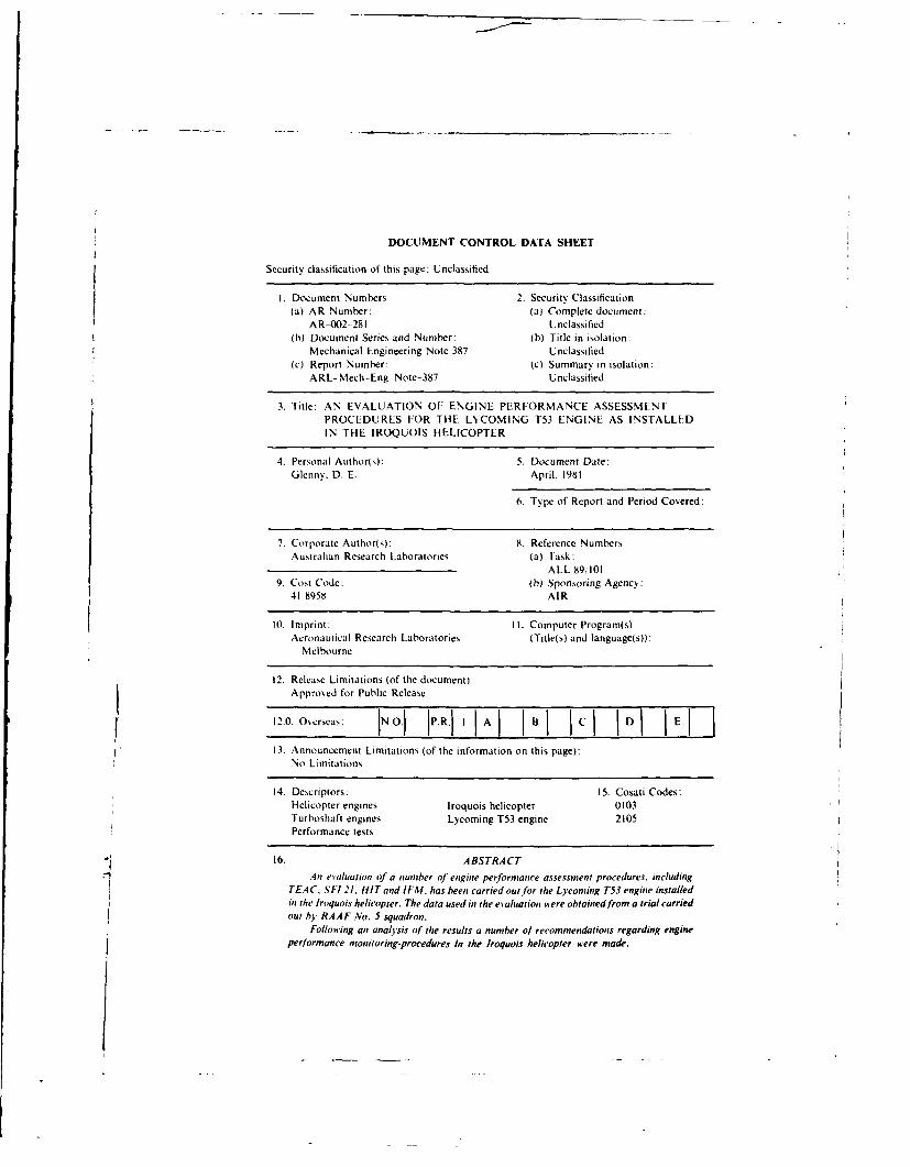
It is recommended that the number of performance monitoring procedures currepitlYbeing used by the RAAF should be rationalised. Further it is recommended that:
(a) TEAC should be used as the basic means frr determining maianunt potteravailahle.
(b) IFM. itith prov ision fir compressor pressure ratio mnnitoring in addition tothe normnal torque and exhaust gas temperature mnioring. should be used toassess day-to-day installed engine pert orniance.
(c) The pilot should be pro iided ii ith computational facilities to calculate. dluring
filight. trends in _CPR. ATOR and .AEGT.
(d) Toping che'cks as required in, SF121 should only be carried out if an, absoluteassurantce of po iter is required.
(e) The requirements for lIT checks should be deleted.
(f) As a means of improving the reliabilitiy anid consistency of the aircraft OATreadlings, conisideration, should be gircn to re-liicati,,g the position of the OATgauge.
Ac 'o:-- 7or
D /LAva -. 1, L, Codes
Dist
CONTENTS
Page No.
1. INTRODUCTION I
2. INSTALLED ENGINE PERFORMANCE-RAAF IROQUOIS HEUCOPTER 2
2.1 TEAC 2
2.1.1 RAAF Operating Procedure 2
2.2 Special Flying Instruction/Iroquois [SF 21] 22.2.1 RAAF Operating Procedure 32.2.2 Implications of SFI 21 4
2.3 HIT 42.3.1 RAAF Usage 4
2.4 IFM 42.4.1 IFM System 4
2.4.2 IFM Trial 62.4.3 Results of IFM Trial 6-24.4 Comparative Monitoring Results 7
2.4.5 In Service Faluation of Monitoring System 8
2.4.5.1 EFD Cell-Comments 9
2.4.6 Interpretation of Trends 9
3. CONSPECTUS 10
4. RECOMMENDATIONS 10
RI FERENCES
NOTATION
FIGURES
APPENDIX A T53-In Flight Monitoring Principles and Data Anayaa
DISTRIBUTION

1. INTRODUCTION
Since the introduction of the lroquois/Lycoming T53 helicopter into service with the USForces and its subsequent use by the RAAF, the aircraft and, in particular, its engine have beensubject to an exhaustive series of regular in-service tests* to determine the installed poweravailable and thus the aircraft performance capabilities.
The Lycoming T53-LI I/LI3 engine, as with most other turboshaft engines, is fitted witha torque indicating system. The torque meter can be used in conjunction with other engine/aircraftinstrumentation to assess engine performance on initial installation or during subsequent servicelife.
A synopsis of the many engine performance assessment procedures used by various operatorsthroughout the world is given.bolw.
(a) Turbine Engine Analysis Check-TEAC/ToppingThis check is used on initial installation of an engine or when the power available issuspect: it relates maximum power available to gas generator speed and engine exhaustgas temperature. The procedures involved are specified in the T53 Maintenance Manual.
(b) Health Indicator Test-HITThis check, developed by the US Army. is used as a GO/NO-GO criterion for po eravailable. It is carried -ut at part engine power prior to take-off atnd compares actualexhaust gas temperature, for given operating conditions, to previously determinedbaseline values.
(c) Daily Engine Condition Analysis-DECAThis check is the same as the HIT check. but it has been renamed by the US Air Force.
(d) Daily Engine Records-DERThis check was used by the US Army and Air Force prior to the implementation ofthe HIT/DECA check. It was carried out at part power condition, just after take-off:it %as discontinued because of difficulties in carrying out the tests whilst flying information and because there were inaccuracies in the correction procedures used todetermine reference exhaust gas temperatures.
(e) Special Flying Instruction 21-SFI 21This procedure, developed by the RAAF. requires pilots on the first flight of each dayt, determine maximum power available, in comparison with minimum acceptable.,orque curves. The magnitude of N, at maximum power is used in subsequent flightPl~nning to set aircraft operating limits.
(i) In Flight Monitoring-IFMThis procedure, developed at ARL in conjunction with RAAF HQSC. was designedto complement and if possible supplement the daily maximum power checks used inSFI 21. Full details of the method and trial results are given in Section 2.4.
(g) Civilian-Engine Operation Check ChartsThese checks, published in the civilian Iroquois/Bell 2,5 Flight Manual (3), are usedto determine values of N1. EGT, Torque and Fuel Flow. Basically the checks are acombination of the TEAC and HIT, using as reference the manufacturer's specificationfor engine performance.
(h) Numerous "experimental" performance monitoring procedures initiated by the US.Army. (4) and (5).
References (1) and (2) detail two of the many flight test programmes carried out byvarious operators.

2. INSTALLED ENGINE PERFORMANCE-RAAF IROQUOIS HELICOPTER
Currently the RAAF uses a combination of TIAC. SI-I 21. HIT and IFM checks todetermine installed engine performance. The first procedure is used on initial installation of anengine or whenever the poswer level i, suspect. SI-I 21 is used on a daily basis. w.hilst the lasttwo, H;T and IFM have been used on a more or less day tc Jay basis during a trial period ofapproximately IN months.
2.1 TEAC
1he TEAC. or topping check as it is more colloquially known, is used by maintenancepersonnel to set the initiat maximum power level of the 153 engine when it is first installed inthe aircraft. and for investigating reported power deficiencies. Detailed procedures for carryingout the TEAC are given in 16). Briefly it involves. "'Climbing the aircraft" until maximum poweravailable is achieved (as indicated by a 'Droop- in power turbine output speed) and thenrecording the following engine aircraft operating parameters:
(a) Pressure Altitude - H,
(b) Outside Air Temperature - OAT
(c) Torque -- TOR
(d) Exhaust Gas Temperature EGT
(e) Compressor Turbine Speed -- Ni
(f) Power Turbine Speed - N
From these parameters, corrected values of NI and EGT for maximum poswer are calculated,whilst the minimum acceptable level of torque is determined from Figure 1. (Lcoming T53-L13)using the instructions detailed on the graph. On completion of the check, if it is found that theobserved torque differs from that given b% the minimum acceptable torque level chart. Figure 1,
then the engine must be re-trimmed, b% adjusting the fuel control unit (FCU). After readjust-ment. another TEAC is carried out and further FCU adjustments made. if necessary. Tl': finalcorrected values of Ni and EGT are then used as the initial baseline reference figures for sub-sequent maximum power assurance checks.
In subsequent topping checks new corrected values of Ni and EGT are determined togetherwith the minimum acceptable torque level obtained from Figure I. their values are then com-pared with the initial baseline %alues and the achieved torque level. Failure to meet the originallimits of Ni and EGT or the minimum acceptable torque %ill indicate some degrtve of enginedeterioration.
The deficiency in torque level can be corrected by re-trimming the FCU to obtain therequired torque level provided the manufacturer's maximum Ni and EGT limits are not exceeded.
2.1.1 RAAF Operating Procedure
The RAAF use of the TEAC method whilst conforming in most part to the proceduresgiven in (6) does not fully utilize the potential of this, the most accurate method available todate, for assessing maximum installed power. RAAF maintenance personnel, having calculatedthe corrected maximum values of N, and EGT and the torque differential, do not monitorparameter variations from their baseline values even on a simple trend chart. Using such amethod, a simple and accurate assessment of engine deterioration can be obtained. The onlylimitation in this monitoring procedure is the large time interval between each TEAC; morefrequent application of the check could be detrimental to engine life and hence counter-productive.
22 Special Flying Imtructlon/lroquois!21RAAF SFI 21 (7) was written following the completion of an ARDU report (2) on the
performance of the Iroquois UH-I H helicopter and the Lycoming T53-LI 3 engine. This report (2)
2

defines aircraft performance limits for maximum power available, take-off and approach grossweight limitations and hoser performance. The inservice use of SF! 21 relies to a large extenton the pilot knowing the maximum rated speed. N max. and torque level. which can he achiesed:in order to confirm these values the pilots are required to carry out a power check on the firstflight of each day.
The relesant procedures, as defined in SF! 21. are given bv the following extracts:
-8. On the first flight of the day, captains are to carry out a maximum power check. ifpossible abose topping altitude, as follows:
(a) increase po,%er until N2 bleeds to 6400 rpm (from a normal operating speed of6600 rpm) or S0 psi torque is reached. (Note: Engine power (SHII) is specified interms of an oil (torque) pressure. and engine transmission is limited to a torqueequixalent of 50 psi),
(h) note the maximum Ni reached and record on the -TOLD- card. and
(c record the maimum torque (achie\edi and compare Aith that obtained from the
Minimum Acceptable Torque Chart.
If the maximum N, (recorded) is losser than the decal N (i.e. the ma\imum ratedN 1 for that gi\en engine) b more than 02.. o the inalllinu torque a\ailablc is lessthan the appropriate chart figure. the aircraft is to be landed and placed unserm ccable.
9. If the topping altitude cannot be reached the powker checks should. if possible, becarried out at or aboxe the highest landing place ILP) altitude to be used during thesortie and the n aximum Ni obtained should be recorded on the (OLD card. If alanding is intended abose the altitude reached, or an increase of 2 C or more in tempera-ture occurs. a further power check at or abose the intended LP altitude is required.
10. Where topping altitude is reached during a po%ser check further check, are not requiredduring that da. . The captain is to annotate the 1-1-500" a hether or not a poer checkhas been carried out abo\e topping altitude. Captains on subsequent flight, are notrequired to carr. out a imaximum pover check if topping altitude has been reachedand recorded in the EF500.
II. If at ;ink stage engine performance is in doubt, a further power check is to be carriedOut-.
(The remainder of the SF! de-eribes numerous procedures for Take-Oil, losers.Approaches and Landings. all of which are conditional upon the value of N, maxachiexed during the dail. SF1 21 power checkl
2.2.1 RAAF Operating Procedure
Numerous discussions held vith RAAF aircrew highlighted the regard with which SF! 21
and I ts maximum poter check wkas held; hosseer little concern was expressed as to the damagewhich repeated maximum power checks could do to the engine. In addition there was littlereal appreciation that, even though a torque of 50 psi was obtained, it did not confirm thatmaximum power would be asailable. nor was it realised that as such there Mas no relevancein undertaking such a limited power check without alternatis e supporting check,, being carried out.
From inspection of EESOO's it was esident that little information, including data., was beingrecorded (as is specified in the instructions for SFI 21) on the occurrence of SF! 21 toppingchecks. It can only Ix concluded that:
(a) topping check results were not being entered on the EE500.Ib) the torque limit of 50 psi w4as being obtained on many of the power checks, or
(c) the check was not being carried out at all-a most unlikely reason.
Take-off and Landirg Data card.5EE00 is the form used by aircrew% and maintenance personnel to record any aircraft/'engine
fault and its subsequent rectification.
3
2.2.2 Implications of SFI 21
The most signiticant implication of the use of SFI 21. notwithstanding the confidence "&hichassurance of maximum poker may gise a pilot, is the serious damage that repeated excursionsto maximum pover can hase on engine condition and life. It i, understood that only in Australiaare such stringent and frequent po%%er checks carried out. It i, unlikely that the manufacturerdesigned or Vifed the engine to cope Alith such sesere operating conditions.
With reference to Section 2.2.1 and. in particular. sub section (b), it is difficult to com-prehend the %alue of carr.ing out a pover check to a limit of 50 psi %khich represents a lo',posser setting for some presailing ambient conditions. s. ithout carr.,ing out supplementarychecks as gi.en in the IFM procedure,.
2.3 HI
1he Health h1di.ator Test is a part load ground posser check deseloped and carried outexten,is ely by the I S Army % here it is used by pilots, prior to take-ol'. as a (i() NO-GO indicatorfor confirmation of engine performance. Detailcd operatintg procedure, are gi sen in (). Brieflthe HIT check requires the pilot to set the engine up to a speed. N\* determined b. the pre-%ailing outside air temperature (OAT) and to record the indicated eshau't gas temperature(EGT). An indicated LGT of 20 30 C) from predetermined IGI baseline ,alues** hasto be reported at the end of the flight. ,,hilsi an EGT difference greater than 35 C is reason toground the aircraft.
2.3.1 RAAF Usage
To date, een though the HIT procedure are deine , in the RAAV T53 maintenance manual(6). the usage otfthis ground. part-load po%%er check ha been spasmodic, and has been dependent,'holly on the co-operation bet%%een aircre\\ and maintenance personnel and the enthusiasm ofthe local engineering officer. As a consequence there are no details of the effectiseness of theHIT check %%ithin the RAAF. tin contrast example, of the confidence espressed by the U.S.militar\ in the TLAC HIT s stems are gt\en in I8). 19). s\hich state that regular turbine hotend inspections may be deleted if daily HIT checks are carried out).
2.4 IFNI
The In Flight Monitoring (Il-N) procedures \%ere de\eloped b\ an ARL officer secondedto RAAF to in.estigate engine performance assessment procedures on a number of RAAFaircraft. The rationale for deeloping the IIM procedures %ias to pro' ide an alternati.e (partload) posser assessment check to supplant the maximum po..er topping checks carried out inaccordance Aiith SFI 21. and hence minimise the potential damage being inflicted on the engineby "repeated" application of maximum po%%er.
2.4.1 IFM System
I he baic prirciple on s\ tiel the It M monitoring s. sit m is based is that turboshaft engines.such as the T53. alhsaas delier the same corrected torque and register the same corrected [T
• The basic criterion for determining the operating \alues of Ni is that no matter %%hat
the salue of OAT. the engine ill be set to a fixed point on the corrected posser temperatureoperating line. i.e. Ni,\ 14 and LOiT I %%ill be constant 'alues.
.* The EGT baseline salues ishich are also functions of the pre\ailing OAT are determinedby maintenance personnel subsequent to carrying out an installatton topping check.
4
and fuel flow 1FF) for a gilen corrected Ni unless the engine characteristics hae changedthrough deterioration in scrs ice. The corrected parameters arc defined as follow~s,
TO R, = TOR ~FGT, = ETi
I F, 1-1~
where Ambhietnt PressureStandard Sea Lcsel Pressure
OAT 273Standard DA T -273
From the abose it folloss, that for a ins en sct of %alues for N 1 OAT. Hl. and cnnec spco-fication performattce data (for the 1-53 eivinc) then tilc cspcctd. Uncorrcted \,ilics of Torque.EGT and FF can be calculated. [Differcnces of the ohscrs cd pcrlimillcc parameter, l TOR.EGli* fromn the expcctedt \aILuc of It OR anid 1 6i1 can be uNCed t0 ASSCN, cninc ifliisllarge a friat ions, in .\T()R anid ALG tiC Ul d he catu c for mlalintncfle act ion.
I sing thle abose \, tcm. all I FMN procedujre \\,j, dcs clopcd ss hich could bc Used cither bsaircreA or maintenance persNonnel.
In the former casethe aircress could b\ simplY enlcrine dali ~into a prc-prograininlcd calcuilatordetermine decrements in Torque or Increments "in ECT.' %\ hilst in thle Klter ease nlalntenaneepersotnnel could use the data ito produce treitd, in engine performance.
Basically the procedure illsoses the pilot recording tile foiloss ing aircraft engine para-meters. MSlidst the aircraft is in stead\ flight conditions
(a) pressure Attitude u
(b) Outside Air Temperature -OAT
(ei Torque -- TOR
f) EsIlaust1 Gais Temnperaiture I G1i
These data are thlenltused as input to au hand held programimable calculator (ii this Instancea M-1I25)aiii hid beeni Ir.s~g~nm ,, orvaitiile icrle\int [MR, ersiis N 1. and I (iT,er,sus 1, etigine performnlc Ilcci Iicaiiotl s es c. I )CtJIll o11 .1 t. Ili l Ikdt li I\ sis prisgratll
are ini ill Appendi\ ..IIle oiLilpiUt, 'l10111 tile prsgrall i~re des a11'n' i11 torLIe .it11d I (.1 I .e. ATOR iand AT G V
fromn iltnlard spedsitiown %JIIie. \ .ir.inll inc~ these In pranletcrs can be mlormiored to
indilcitc dcicfiorjuilill o eng ,ine pert .orflcC
rile aisanittge ol, tile IT \I sINten, aie
1. 1I -iiii p'crillc'c 'sesnlcilt ,ill i-c carried out at power ec ls e!rcailer tilan tile
fill Jicck. .\ct lnot Ilecessaink it hel, m.nnlail powecrs insoisd Ini the I [A( or St 1 21,
2. Both i to rq iieand I. GT pertormai in.e. hae 1110nIorcd.
3.Resaill cii he aylledi ill Iivil 11 pirlot rrosideil c:alculator, I\, ilible. and~ tihe
resullts used 1'.\ tlriti llcCn lser,01ll llclt deterinte trenld, Ill ipie pcrlortlliaiwc.
4. IDirect1 pilot insolskeilet til It NI c:hecks %' .iii resuili it nmore colISitellI dLi.i rcordingand, i11- pros ide, tile pilot 551111 .11ltl Imediate re~ord oll engitne conlditionl degraitioit.
5. 11r req iired. tile envine 1pec01-0c1t01i d.i Ia cirs es held ill tile calculator can be fe-con tiuredto5 retlectI tle felCrorlian nce iIlie .I siieiginIe being tested.
A fuel tioss meter is not ilted to the RAA-F Iroquois helicopter.

2.4.2 IFM Trial
At the instigation of RAAF. HQSC Aircraft Engineering Division and %%ith the cooperationof No. 5 Squadron based at RAAF Fairbairn. a trial of the IFNI ssstem was undertaken onboth the B and H model Iroquois helicopters. Co-operation ,ith the No. 5 Squadron had theadded adantage that some of the helicopter, Aould be operating in the arduous conditionsof the Sinai Desert. %%here Australia ",as contributing to the Lnited Nations peace-keeping force.
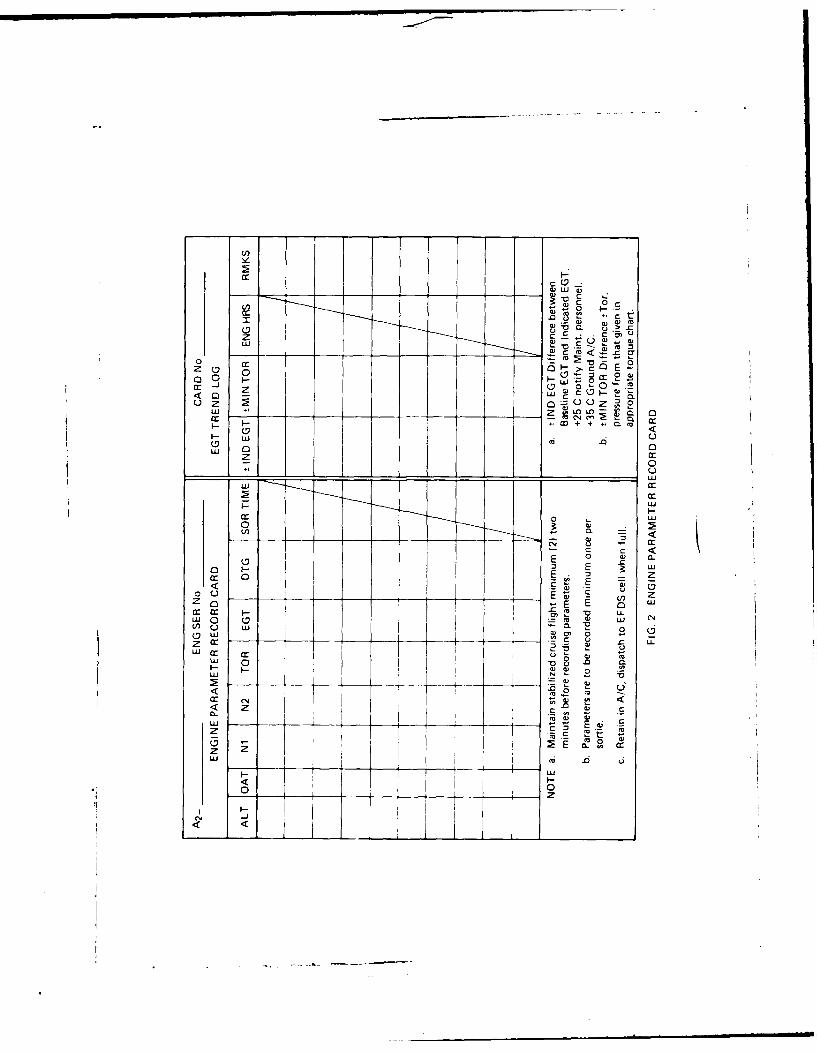
The IFN trial commenced in August 1976. following numerous discussions ,.ith RAAFaircrev, and maintenance personnel. The instructions covering the implementation of the trialare given i (10). Briefly this instruction required the aircrew to record on a special Engine
Parameter Record Card. once per flight under stabilized operating conditions, the operatingparameters listed in Section 2.4.1. A cop. of the Record Card is given in Figure 2. Once the
card was complete. l0consecutie readings, it %%as to be dispatched to the Earl. Failure DetectionCell (EFDC) at Fairbairn for data processing on an HP25 calculator.
For this I'mited trial, it "as not proposed to carr, out in-flight anal.sis of the ra, data.and consequentl, the pilot insolsement Aas limited to recording the required engineaircraft data.
At the same time as the IFM trial was carried out the pilots were requested:
(a) to record results of a HIT check, and
(b) to record details of an, maximum poser check undertaken.
Both sets of data sere to be noted on the card sho,.wn in Fig. 2: the HIT results in thecolumns marked EGT Trend Log. whilst the TEAC', ,ere to be included as part of the IFNrecords on the Engine Parameter Record Card.
2.4.3 Results of IFNI Trial
In the course of the trial, engine data %kas logged f r 22. T53-U. 3 egne-, an,d 17. T53-tl Iengines. Some of the data obtained %%ere limited in range as engine remos.als in the Iroquoiscan. on occasions, be ,er. frequent.
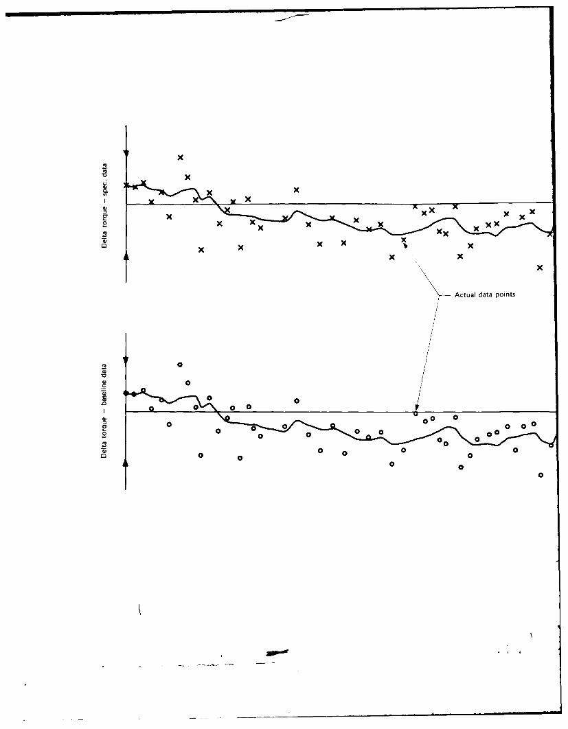
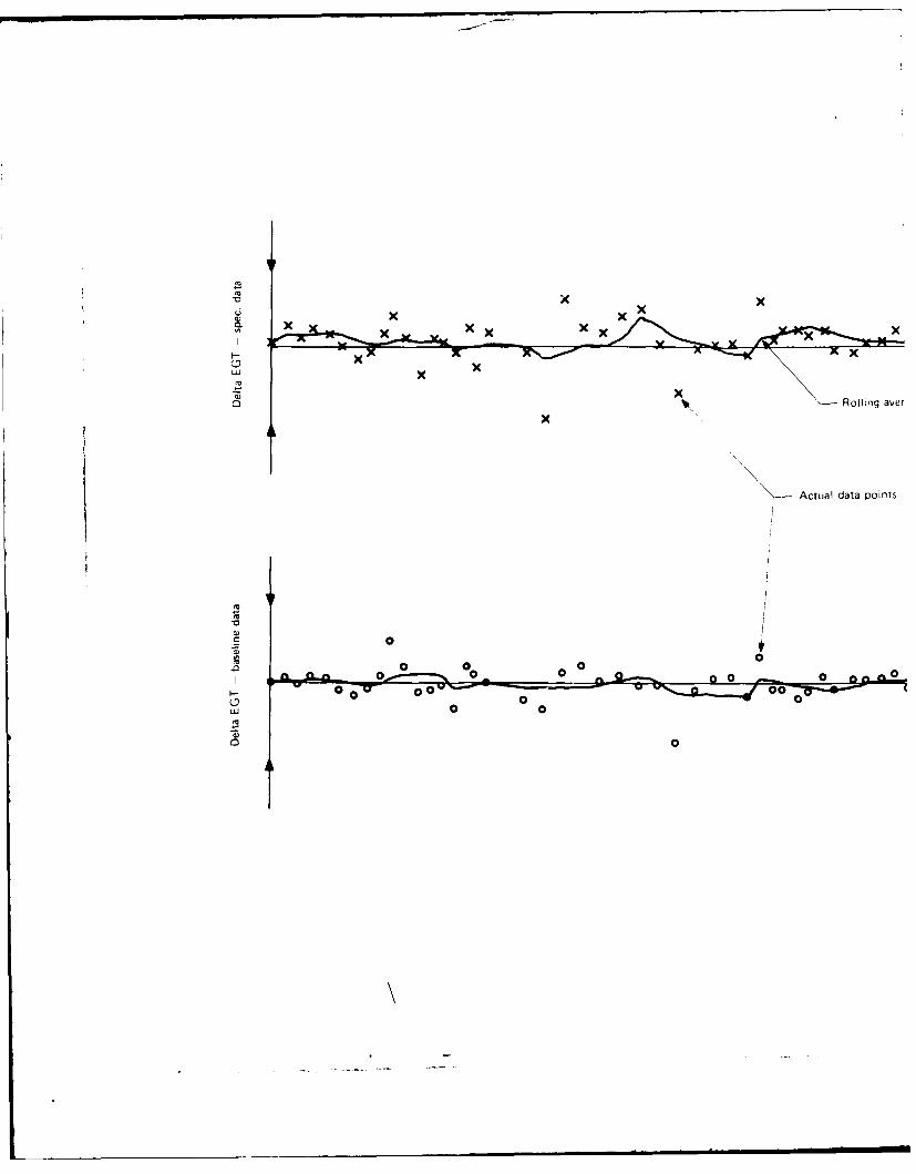
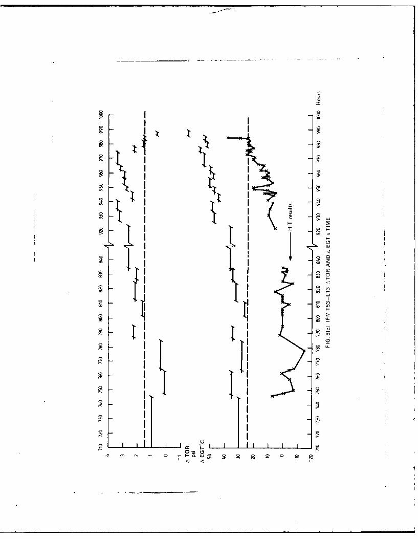
Torque and exhaust gas temperature deviation, for each of the engines \%ere anal. sed bothat RAAF Fairbairn. ". here correctie :ictiot could be undertaken if found necessar\ and atARL wshere an oerall analysts of the IFM. HIT and topping check, \%a, carried out. T picalresults of the ARL analysis are given in Fig. 3a. b. c and d. The respectie plots shov, thefollow ing:
(a) Figure 3a-Comparison of SHP, "ersus Nic' deried from obsersed engine results.with engine specification performance and the engine's actual* baseline performance.
(b) Figure 3b Comparison of FGT, \ersus N 1,- derised from observed engine results, withengine specification performance and the engine's actual baseline performance.
(c) Figure 3c Deviations of observed engine torque from both specification and actual
baseline performance of engine being monitored.
(d) Figure 3d Desialon of observed engine exhaust gas temperature from both specifi-cation and actual baseline performance of engine being monitored.
In Figure 3c and d a rolling averaging technique for each data point, defined by AHrAs atn =(An -,n I - An 2 . An 3 • An 4) 5. was used to reduce the scatter in the resultsand gise a smoother trend graph: the ARA5 results are given by the continuous line. The IFMresults anal.sed in the EFDC. at RAAF Fairbairn. \here also smoothed, but in this case thesmoothing was obtained b\ dividing the data into groups each consisting of five results andthen taking the a\erage of each group. The effect of this technique can be observed in laterpresentations of the IFN results in Section 2.4.5.
An analysis of the results given in Figure 3a and b. which are typical of all engines monitored,shows that esen though the slopes of the baseline performance curves (for both torque/SHP
Actual baseline engine performance was calculated from the first 20 IFM readings obtained.
6
and EGT) can be different from the specification performance curves, the oserall differences inresults for the torque and EGT deiation plots given in Figure 3c and d respectisel are minimal.Consequently in computing torque and EGT differences, either of the performance curses.specification or baseline, may be used. The ad,,antage of using engine baseline data is that atthe commencement of plotting ATOR and AEGT. the deviations are sensibls 'scattered' aroundthe zero de\iation line: see lo\er curses in Figures 3c and d.
The major limitation in the IFM trend plots is the scatter of individual readings, and thisis the reason for using a smoothing or aseraging technique. The scatter is a direct result ofinstrumentation reading error. If the pilot had access to a programmable calculator then theIFM results could hase been checked inflight and if necessary retaken.
1he follossing table shosss the sensitisity of instrument reading errors on the resultantATOR and AEGF salues.
lnstrument Resoluir.,P TORQUE EGT
100 ft (Altitude) .0 I psi 0 CI COAT .0 4psi I C0.1 ",, N1 0.3psi I C50 rpm N2 02 psi 0 C
From the abose table it can be seen that the OAT measurement has a most significanteffect on the resultant 'calculated torque'. The location of the OAT gauge, at the top righthandside of the aircraft s\ indscreen is not conduci e to gising consistent \ alues of the ambient outsideair temperature. a-, on maitt o,:caions tie probe is exposed to direct sunlight. Figure 4 shousthe location of the remanining aircraft instrumentation and exemplifies the difficulties suhich pilotscan hae in reading tile required data.
Further detailed anilxses, of' all T53 engines monitored are not presented here, rather 5example. are gi\ en in the ne\t section. hese hlimited samples of trial result, are sufficient toenable a comparison of IFM. MHI and TEAC checks to be made.
2.4.4. (omparitiie Monitoring Results
lie monitoring rtsllts gien in this section ire presented in three groups:
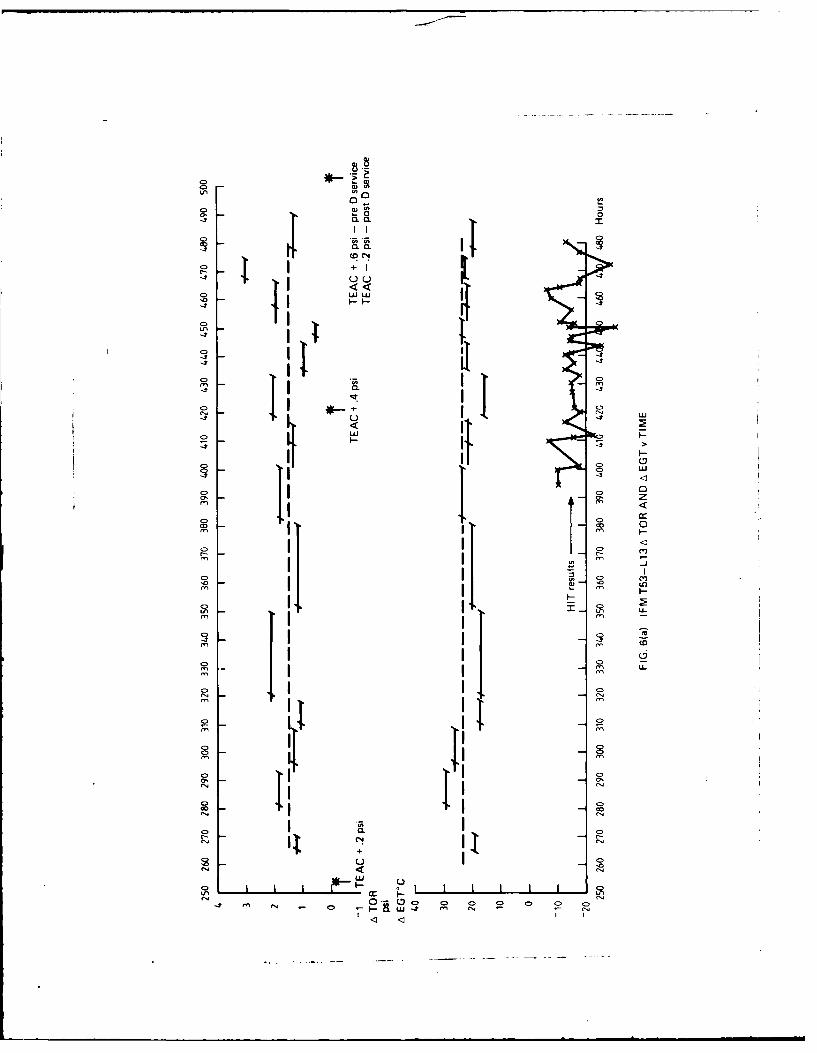
la) I\\o T53-L IS engin, operated front RA..F Base Lairhairn. tIgure, 5 and b.
(b) One 153-LI I engine operated from RAM Base tFairbairr. I gure-.
lt T\%o T53-L13 engine, operited b.\ tile RAA1 \kith the L NILF in Sinai. I igure, ,S and 9.
In ciLh Itigure tile IFM resilt, ha\e been presented uilng a simple a\er.ige of cach grupof ire dat,l point,s (- 1) raiithcr ihln the rolling a\crag. ic .hnlque used in I iires 3c and 3d.Indi\dual etgite haslines for both A OR itnd At(61 ir.h\e been caleulited front the tirst S0dalai points recorded ,ind ire denoted b\ the dahcd line I I. the difference set\tseen theind\ Idual tbasclines and the AItOR 0 0. ALGT - ( abscissa ' .Oreent, the sariation of i gi\enengttc front he ditJi b,ie used to define tle performance of an "a\erage" engiine. The lEACor topping hecks cirrued out on cash aircraft ,ire indicated at the point *; included it thatpoint I th degree of concurrence of engine torque ssith tile Minimum -Acceptable torquedcried Irom I gure I. Also iniluded in Figures 5-9 are the LGT trends derised from theHI T check,.
s. Anal.,i, of the result, for the first engine. Figure 5. shosss that during the first 1200 hours
there \%as no significant change in torque or EGT differences: howeser in the periodI 30-1400 hours there sAas a step change, 3 psi, in torque le.el: throughout this periodthe -GT lec'el sitied fairl. constant. The initial torque lesels are confirmed bs the twoTL\C, carried out at time 1075 and 1235 hours. A comparison of the HIT results showks
7
a slightIN erraitic response part Iat t hro nith the readingt hut in generalI con Forns tWthe %allues eale iLi ted f'ront the IF-N results, The Frall in torq ue ci ci could not be relatedto an'. discernible faUlts ien the enc'ine %it s ci ent uall'. remot ed front thle aircral'. thedeterioration could ha3\c been sinpl\ attributed to erosion of' thle compressor bladingss hich \it,- cident. Anal.\isisof the results vii en in Figure 6 f'or the second engine sho",
tha agin hee i isgenra ageemntbetiseen the torque let ci trend, as determined f'ronttlie IF 1:M mom tori ni and the I1-. AC-. carried 'oit at time 255. 420 and 500 hour'. arnd
filie ternperallire elsk inricrared li the f il and I I NI t rend,. tle latter agireenment ismost signilicai in that during the final 100 hroirs oi nritoringi.there \Aasrapid increarse
in the I -G I tI lirence lcc ls Art increase of' iter 3(0 C s a, inrd iCated 11 hothi met hod,.lit shoul d be noted thIa t tire ifferences in let el, tor thre t iso I (ii trend,. result,. can be,ITIbuICI toI art injitil inc~orrect estimarti oI rte I I baseline \aliresi. Inspection ii'the torque trerrd-. lIIs liii there \ka-. a riduail rise i it torqe etieC-I Untill tire list tsithorr of- moiirtorinrg is hen there is as a dro, 011 apprvominatl\ p I i-. fa1,ill it isa assoct-dired is1rr tire r-ipid rise ii IF(i I .s Ir ere a perik Urtateriged %ilireofl 78 C %i.is recorded.()n irtspec~iot of rite enie it \\,is tititi lhit c.erecra n oter I1 0" the Wi stige
poue r iur-rr irnIct ruiide iatcs himIi 'cetrretl. RCeplCerilrt f thre p'siC erhrineroice ring redutcd the hile rerte ito appIromimtiel 20i C. a lcie Icrssr %i t (ireinitial installedt %alue.
ii. A\ sitiilar L0ott1stenii. of re-.uit, is h.rl.t ill I itic for I5-I I engin1e ( FB iodel1riiliii01 irkraitj. Iii this Nar-. hisseser it', errirre sietenrTAIorr s\ta- indicated b\ eithert ire AF-OR ior Al (if tmciii-. ittitel isri-s:c ekirng iih kitoiri I I \C, as itrilcited01n tlIe inure. ornfirmir that little it in\ enigiedepridiior tad oiirrecd during tliemor ttiii rg pio~ld. (iripi1rion of Al (il trends ii tnt fill data is is riot possible as,at that tinme Ill I pricdlircs for L-1I I engines rail ntt been introduced.
i.lie resuiltsg perr in I igirre. S aind 9 are o'Ir tis of thre heltiiopter, is Ic %sere operatedin tfie Mirddle Last u irli tire t, M NI I lie dcesert ecm iroririerit is pirtierilirk arduous ont
L13 erincie a- sari be seecn the i at mii-e~ fl ohli i iorqute lel lot s bhohth engrine,.I fire 16 1 trendis gin errit I Ltite 'I str0%k a tiroderate rise iii tes iililsi titat in Irigure 9
does ntt 1101tire. winIl tile List I5 reaiing,. Ar this pornt a tiri-uimu de,:ceett sf' 42 Cf'rontl tire mreain lin t ic- bate ib F ile change ii I-1 is \as iriniiiitei identified as.ai faIint ill the I (I litess. .tals III tire trquie andi Il tiIrends u.rggeqt, that theretad been a dii shatipc ill rte irtihle inlet gUie %tite 0'i I( ) sciredulitig. Ithis
consItistoti \%i- i onlirnired ,nt ser icinig- [lie crirrne ishe ierisicre erisiont arid -roll trier-\sas ibseti ci on i lie Ist rId -rIll stag ci,:mpressor blades. A nioditic:atiotitn tire leadingedee sestuti (it tihe tririsortic' blades, %korld. cwer though thle "% I\ (i actuation si stem\ii-. opcraiirt oirrestk. resu1 lt an etCLUsIs change Ill tire \ (i's scieduiC. The torquetrenris dirernriid tilu rthe 11 \I iscre corifiritned h\ a rnurmber of* I I A~s undertakenInn rigi rite rrirwrii peiod. I ese airc also indic;ated (iri gures S and 9. Ilie TEACs
for tire enprgi n u tiit I igae I) are coipisaed bh the f'act that at l Control L,1itcrairge ira-. tde luriing lie sotirse of' tire 11-I and tire Oe ,ct ort tiorque icici hateh)ad tii e Corrmpernsated t'r. Ifr is periraps iunfortuntate thai t1t Ill I results isere asailabie.esert ihtirii it is iidrisierrr tht Ill F mnirtrirng \its being carried trt( idmst tirea inr i t i crc hencr o pe ruted iitt tire Niiddle l ast. I -or if tilie ill Itrends had mirrored tine11 NI-L I trernd' artd Idrlrc had been linitesd tir 111I trentd- alone thnt the seicrecinipressir itc:r uriitrared hi tire Lharnes i it tire IF MI torquie li elN s ikiu d not ha. e beenpicked rip.
2.4.5 In Sersice Evaluation of Nioniforing S%tern
An anali of the If\1i,] I I estirrs isa- itideriker h.\ tire I D-C of' No. 5 Squadron.at R AAV F-Fairbairn. A citniprehiterise repot iI if L11 engr ~ tic eet .aid tretir rela ted cur us is g'i enin Hi 11 For tire period 19761 97S. 1 ir 15 mnthis iof' this periodi. is lin engirre nmonitoring \%asbi~tng carried out.- a tittai irf 53 errines tic re defes ted, corn pri sed of 1 6 1 or mecra nical I ausesIssear debris in oil, arid spctrirtrie~, )rif 13 F r ernisdi nani related causes and thleremaining .24 fur iotiher reaisonts.

Of the 13 engines defected for thermodN namics causes. maintenance action on four engineswas initiated directly as a result of the monitoring procedure,. either HIT or IFM. The remainingnine defects were indicated bs other , a "s: for example. as a result of schedule sersicing orthrough engine torque fluctuations. Retrospectixe analisis of the performance trends, vhichwere not always able to be kept up to date. shoved that in four cases the IFM trends had reflectedthe defect, whilst in two cases marginal trends were apparent.
For the remaining three defects no monitoring information %as asailable.A sursey into engine rectifications as distinct from engine defects indicated that:
(a) three cases of burnt or damaged turbine nozzle guide ,anes.
(b) three cases of compressor blade erosion, and
(c) at least four cases of gauge malfunction.
had been positisel% identilied b the IFNI and HIT monitoring procedures. The total numberof rectifications carried out during the period and the number which ,,ere thermod,,namicall'related is not known.
2.4.5.1. EFD Cell-Comments
A summarN of the FIDC anal)sis can best be gixen bh. quoting the following extracts fromtheir report ( I I.
"Ia) HIT as a GO NO-GO sxstem has been successful in confirming defectixe engine, andinitiating increased pilot recording, leading to full inestigation of engine (conditiont.
The sslem has been most successful in such areas as indicating It the pilot ihat theengine anti-ice s stem is operating prior to take-off.
(b) The HIT s.stem has experienced sexeral small problem,, primaril. in the sctting ofthe Baseline FGT. It has been found that there could be a Heat Soak through the engineduring an. sutained period of operation: this has led It) lower Baseline I-6f- saluesbeing set.
Ic) IFM, the long term monitoring procedure has been successful in t'o* cases. Becauseof difficulties ii the interpretation of results due to FFl)C inexperience, and (accurac.of) pilot recording or lack of. seeral situations ha\ e occurred where the csstem indicaledthe problem but it was not recogntsed. How\e.er this situation is gradually beingoxercome.
(d) IFM problems experienced hase been: irregular pilot recording of parameters an,]instrument reading iepcatabilii\. leading to error results in AIGT and ATOR \whichcan ha'e large xariations bet-,een readings. This has led to a \,stem of as.eraging wherethe last knowAn aerage figure is axeraged wxith the last ten factors. This had led to amore consistent 'Signature of engine health'. It has also been found that when a problemis initially indicated by an increasing HIT EGT, the number of IFM pilot recordingsincreases. Pilots are also using prexiously recordtd ligures as an a'erage of their cruiseparameters. This has made them more aware of actual cruise .alues.*" (End ofquotation from I I 1.)
2.4.6 Interpretation of Trends
Throughout the analNis of the IFM HIT results there has appeared to be some diflicult)in interpreting an particular desiation of torque or desiation in exhaust gas lempeiature. in
Comments "ere written prior to complete evaluation data being a\ailable.
SWhilst not disagreeing with these last two sentences, problems can arise in comparingactual engine performance, if the H, and OAT are markedlh different. Pilot analysis of recordeddata (using an HP25 sa. ) \would obsiate this problem and w ould appear to ha\e a further bene-licial result, in that any suggested deviation in either ATOR or AEGT would be more rigorouslymonitored b. the pilot.
9
term, of ss hether there % a an engine fault or not. \\ it these simple. limited. data recordingt ,ch niq ues it is rot possible to diagnose rigorousis enuine1 fault,. P'roblem areas can onis beinferred -A ith the build up of' espcriecie. More comprehen~ise gas path ainaissis% techniques canonly be used ss ith ant increased range of' data collection and hence engine instrumeniion. Inthre case of the L.scoming 1531 engine. ss hich sulfers %ery markedls from compressor erosion.at compromise may lie achicewd h\ monitoring compressor pressure ratio (CPR). and determiningits \ariation ws th corrected engilne speed. A decreasing AC'R* \Ith time stould grie a morespecific anid immediate indication of erosion than that achieved hs inference from ATOR andAEGF. The reqlUired (PR \ersus \I( performance data and anralysisN technique could becombined "iith tire Current I FM procedures,: the resulting trend plot% %%ould monitor ACPRats \kel1 as ATOR and Atf G . For this N~ tem to he elh~crise the calculator programming capacityci ott d has e to he intcreased and. if' possible. fu rn ished %it i I a continuous memory facilit.
3. ('ONSPECTL S
From the a nal sisf itIhe I :I- NIia a(and i IT results \x hen as ailable) it can be stated, not-it hstand ing particular comnmentis made pre% us thlat:
ai i Si m iai r t rend -it [C I atre prod aiced usi rig errt her I F Mi or II I proced ures.
h)I-[he Hi I ss stem is uabl e to i ndicare some forni of engine degradaition. notablycornpressOr erosiiuri Henice sonic relianrce m ust be in sn to at form of torque OllMImonitoring.
tc) TrendinL of IF% I data in terms of ATOR and AFGIT can adequately indicate enginedeterioration oser at period of' tinme. and can thtus he used to indicate poster ia alabless itbout resort to frequent topping checks.
(dt There is at requirement for at complementary check to asess direcrl\ the compressorperformance and its deterioration. This could be achie~ed by basing an [I FNI typecheck for the compressoir pressure ratio, ic. CP'R mronitoring.
We Ma sjmuti, pots er chick, iare on I reqired si ienes er inlsta.illed engine performa ne is
suspect. In this case, detailed turbine anay sis check ( tII AOi should be carried out sothat Nit and FGT reference lceel are reciorded a, %%ell as, tre minimum acceptabletorque figures.
(f) All checks. TFAC. filT and IF.M ire compromised by\ the location of the OAT gauge:consi hera lion shoul hI e gi sen to locit i nvg the inst rumnit to t hat it is out of the line ofdirect sunlight.
Currently there is at surfeit of engine monitoring procedures being carried out on theLycoming engines of the Iroquois helicopter. I lie II I \1id HtI I procedures introduced, as atrial, to osercome the detrimerital effect, of thie topfing hcks carried ot in St I 21 hate thepotential to furnish equal if not superior ittorriiriw remi rcing engine conditions pros ided theoperating instructions are carried out correcils -It is to benoted that checking the engine to amaximium torque of 50 psi (is detailed in SI- 21 j does riot gis e arts indication oh engine perfor-mance unless engine speeds and temiperature are recorded and analysedl: this \Aould then beeqursalent to an II check.
In summary the number of engine checks should be reduced and effort Concentrated onaccurately, recording and analysing those results obtained from the remaining. more precise andpotentially less damaging checks.
4. RECOMMENDATIONS
1TEAC should be used as at basic reference maximum poster av~ailable check, The checkshould be carried out by squadron test pilots and data should he fully analysed by
ACPR -Actual Comprressor Pressure Ratio for actual corrected engine speed -- BaseirneCompressure Pressure Ratio at same corrected engine speed.
10
maintenance personnel to define N, and EGT limits as well as minimum acceptabletorque levels. The results of TEAC should be monitored (trended) from one check tothe next.
2. IFM, with the provision for CPR monitoring, should be used as the pilot's day to daymethod for assessing power available. Data should be analysed inflight giing trendsfor ATOR, ACPR and AEGT: these results would be subsequently used b) maintenancepersonnel for determining trends in engine degradation. Under these conditions SF1 21topping checks need only be carried out if an absolute assurance of power is required:the requirement for HIT checks would be deleted.
The consequences of these recommendation, are that:
(a) The pilots should hase access to a programmable electronic calculator s.th anenlarged and continuous memory-e.g. HP 34C.
(b) An engine compressor pressure ratio gauge. or means for calculating engine com-pressor pressure ratio should be included in the engine aircraft instrumentation.(It is to be noted that pressure tapping points are asailable. as CPR is determinedon the engine test bed).
3. If Recommendation 2 above is unacceptable (cost only) then the IFM monitoringprocedure should be combined with SF1 21 such that any time the SFI is carried out.the data (including N1. torque. EGT etc) should be recorded and made asailable roranalysis by base maintenance personnel.
The HIT check should then be retained as a GO NO-GO indicator prior to take-off.
4. Finally, consideration should be given to relocating the position of the aircraft OATgauge and sensor to reduce the effect, of direct sunlight on it, readings.
II

REFERENCES
1. Kos. J. M. et at. FeasiniliIN Investigation for D)etermining Army Helicopter GasTurbine IE'ngine Maximum Po~er Asailable. LJSAAMRDL TECH.Report 72 58. Feb. 1973
2. -L H-Il II roquiois~ Performance Es aluation. RAAF-ARDU Report
No. TS 1031. Phase 1. No%. 1976.
3. -MOD)EL 205A-lI Flight Manual T5313A or T5313B engine.Section I\. p. 4 1. 4 8. Bell Helicopter Co. Dec. 1971.
4. Provenzano. J., et al. L!H-IH1 AIDAPS lest Bed Program. USAAVSCOM TECH.REPORT' 72-18. Aug. 1972.
5. Butcher. R. R.. et al. UH-IH AIDAPS Test Bed Program. USAAVSCOM TECH.REPORT 72-19. June 1972.
6. -. T53 Maintenance Manual RAAF -AAP 71 13-(K-2.Section 5 73 5-74.
7. -Special Flying Instruction: SF1 Iroquois, 1 .5 M~ay 1975.Subject: 1,11-I H1 Take-off Landing Procedure,.
8. McHugh P.C.. L.S. Arm% As iation [)igeto. Oct. 1973. p. 10- 15.
9. R....f- File W1520) 4 41h(38). Subject- -T 53 Engines-- UHI Aircraft18 Dec. 1975.
10. -- RAAF HQSC 2602.17,76. Pt. 1 (25), l2/Aug./76.
HI. RAAF HQSC 2608'132/20-6. Pt. 1 (41). 31/May/78. ANNEX B.Early Failure Detection-- General Analysis.
NOTATION
CPR Cornprevor Pressure Ratio
IN CA Dail% ILngine Condition Anal ,is
ML R D)ail.% Engine Record
I-C rT Iha uq (;is Tempera ture
I Ct t ucl Control t nt
II Fucl I lm
11C heath Inidicator lest
PI, Iressorc Altitude
InI X I light %lonitortiLg
K Conmersr'n I titor for T',r~lti in lh It ito SHP'
NI nigine Speed
(A I- Outside \i r I emperat are
Sul SpecLial I king Iniruoiin
I I AC I iriri I niginc Xi~s he~ k
JOR I riue
VIG% \ .iri,ihlv Inlet (,id \jnc
Seinperaiiurv Ratio
I're-sure RAitW
A n, rrent or Decrement
Subscripts
Inlet
2Outlet
C Corre~ted
MxIi Nlaximunt
RAN Rollingv Aserage (\i\.here Nis number of item, being a~eraigedl
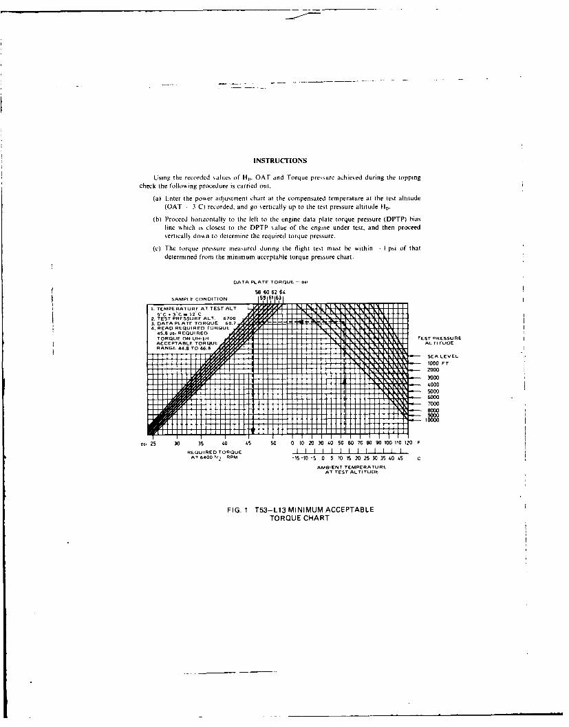
INSTRUCTIONS
Using the recorded "alues of Hp. OAT and Torque pressure achie'ed during the toppingcheck the following procedure is carried out.
(a) Enter the powser adjustment chart at the compensated temperature at the test altitude(OAT - 3 C) recorded, and go sertically up to the test pressure altitude Hp.
(b) Proceed horizontally to the left to the engine data plate torque pressure (DPTP) biasline which is closest to the DPTP %alue of the engine under test, and then proceedvertically down to determine the required torque pressure.
(c) The torque pressure measured during the flight test must he within - I psi of thatdetermined from the minimum acceptable torque pressure chart.
DATA PLATE TORQUE - PSI
58 60 62 64SAMPLE CONDITION 55 6t 63
1. TTMPERESPRE AT TEST ALTS U R9• ;. 3'C 7S12C; A .''Y /. I l] I r N N l i[3 N i' I]
2. TIS PR URE A T. 71 1AL1 iTUDE'
32 DATA PLATE TORQUE 000
T3000
t 4. ~~~~~~~READ REQUIRED TORQUE II!IIIII]IILI[N kP .k ' ~45.8 S$IREQUIREOD rayrF li[P, li M LIl Xl .I1TORQUE ON UH-1H1- ,y1 [ 1I]]I]I. %1].II. LM TEST PRESSUREACCEPTABLE TORQUE/ 4r,,a ALTITUDE II[I IIII ILF X I I
t ~~~~~~~~RANGE 44.8 TO 46.8 J4,J.r#lI1 ]1] 1l[I|]]]IIl, kM IIIM.
iii ]] ll ] J., .,W [ [I~ II I! II II II ] [I q" N % -N -'q - I - g l 'P '
SEA LEVEL
J J 1 11 1 x NJ . .] I000 FT
if 2000
60007000
000
D25 30 35 40 45 50 0 10 203040 50 6070 8090 100t10t120F
RE QUiRED TORQUEAT 6400N 2 RPM -15-10 -5 0 5 t0 t5 20 25303540 45 C
AMBIENT TEMPERATUREAT TE ST ALTITUDE
FI. I iT53-113 MINIMUM ACCEPTABLE
TORQUE CHART
20-m
z c.w<
0 - -
z
0 cr 2
< 0 - .
cc 0
LU -E E u
10 +1 0.
0 -__~~c <__ _ ~LI ~ .- Occ
Wc <
0 C_

140 Lyclat 308. daily inflight monitoring eng. no. LE L13/16125
kv
130
120
///110 2x100
V x
u X
xx
x
90 - xcj) x X X
70 - x
60
50 1 II
88 90 92 94 96 98 10CN 1 Corrected
FIG. 3(a) COMPARISON BETWEEN SHPc AND Nic FOR BOTH OBSERVED ANDSPECIFICATION PERFORMANCE

Lydat 308. daily inflight monitoring eng. no. LE L13/16125
600
580
560
" 540
00
x0
x
520 x
Soo
480
oII I I I
90 92 94 % 98 10C
N i Corrected
FIG. 3(b) COMPARISON BETWEEN EGTc AND Nic FOR BOTH OBSERVED ANDSPECIFICATION PERFORMANCE
x
~0 x
0. x xx x
xx x x xC. x
o x x5) x
x
Actual data points
0/00
5)*0 /0)0
5)0 00. 0 0 0
0o 000
00 000000 0 0 0000 0 00 0 0
0 0

Lydat 308. daily inflight monitor
x
K x
xxxXXx x x x X X xxxxxx x x x x x
X xX X
-Rolling average XActual data points
0
0 0
00
0 00 0 0 0 0 0
0 00 0
FIG. 3(c) DEVIATION OF OBSERVED TORQUE FRACTUAL BASELINE ENGINE PERFORMA

Lydat 308. daily inflight monitoring eng. no. LE Li13:16125
Time (hrs)
X X x xx
x X X X
X X x x x xx x
0 Time (hrs)
0 00 0 0 0
000 0
0 00 00Q 0 0
0 0
0 0 00 0 a 00
FIG. 3(c) DEVIATION OF OBSERVED TORQUE FROM BOTH SPECIFICATION ANDACTUAL BASELINE ENGINE PERFORMANCE
6x x
wx x
0t Rolling aver
Actual data points
0Z
00

Lydlo
X xxX
X X
Rolling average
Actual data points
0:0 00 0 0 0 0 0 0 0 00 0 0 0 0 0
0
0
0
FIG. 3(d) DEVIATIONBASELINE E

Lydlat 308. daily intlight monitoring eng. no. LE 1-13/16125
XXx X X" x x xx xx Time (hrs)x
0
00 0 Timeit (hrs)
0
FIG. 3(d) DEVIATION OF OBSERVED EGT FROM BOTH SPECIFICATION AND ACTUALBASELINE ENGINE PERFORMANCE

Engine speed N1 "Rotor" speed N2 Altimeter
Engine torque meter Exhaust gas temperature
FIG. 4 INSTRUMENT PANEL IROQUOIS HELICOPTER

LA m
I a
C> 0:2 < L-
C - C'II
0 (0
I> 0
0 0L
[ILcc,
C0*

I Ii
8 Ii 0
a,
U' IiC0I $o
I 11 -*
I I Ii -- II0enI
4 U I -,I 1 ::I III 1a 0- cI
01 ~ 0
CL
+1
II ILI --
U,01
o ii i'1CD-3L
0 UJ
C> C>
o -L .1o 0
0 0
'71co 'IoI
0 CD , 0,
IU 4

0
ii 11I 0
0 0
, -,
LnI
I >I I 'a II I
I I j Ln'a I ID
I CD
1 rrUu
0
l Izo I30C>
Oa'
C,0
a C-a'
I <
Cos I1 <
I X
C0 Go 0
cc 'o.IIU-
-
0 '~I 6
1 C>
06 I C
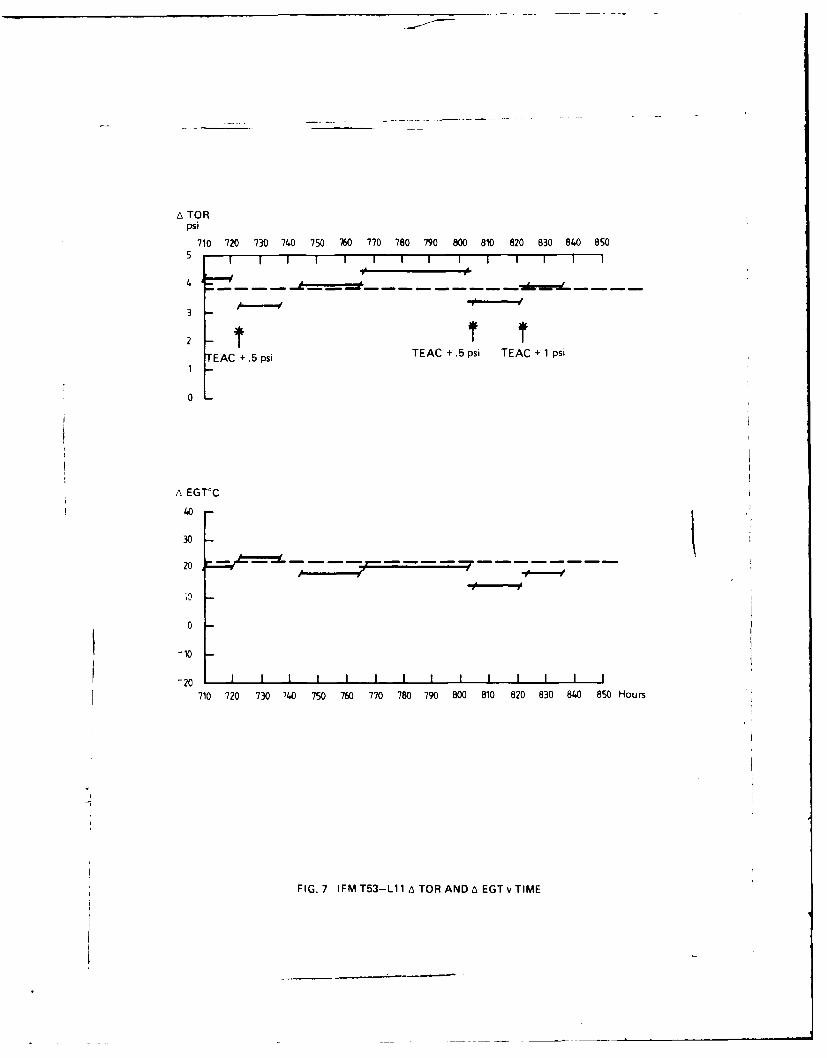
A TORpsi710 720 730 740 750 760 770 780 790 800 810 820 830 840 850
5
3
2
TEAC + .5 psi TEAC + .5 psi TEAC + 1 psi
0
A EGT°C
40-
30 -
0
-10
-20 1 1 I I I t I I I I I
710 720 730 740 750 760 770 780 790 800 810 820 830 840 850 Hours
FIG. 7 IFMT53-L11ATORANDA EGTvTIME

IS 8
00
o<
I IvI ILI 0II IL
ccwF, 12 I r 2

m- 0
EU E(D, 0
ii _ III ~cC
________ n ccL4-
'liEini
.00
0- D
I 0
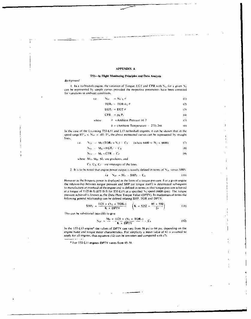
APPENDIX A
T53-In Flight Monitoring Principles and Data Analysis
Background
I. In a turboshaft engine, the variation of Torque. EGT and CPR %,ith Nj. for a given N2
can be represented by simple curves provided the respectise parameters have been correctedfor variations in ambient conditions.
i.e. N I,. N l,% 1? (1)
TORy TOR/6N 0 (2)
EGT. EGT i (3)
CPR P3, Pi (4)
A here ll =Ambient Pressure 14.7 (5)
6 (Ambient Temperature . 273) 288 (6)
In the case of the Lscoming T53-LI I and L13 turboshaft engines. it can be shown that in thespeed range 85",, < Ni1 < 101 "5",, the above mentioned curves can be represented b% straightlines,.
i.e. N1, = MT(TOR.xN.) - CT ( here 6400 < N < 6600) (7)
Nw i M kx EGT. CF, 8)
Nic = M x CPR Cc (9)
%, here Mi. N1 v. M are gradients. and
Cr. C., C. are intercepts of the lines.
2. It is to be noted that engine po%%er output is usualls delined in terms of N1, sersus SHIP,
i.e. Nic = Ms , SHP(- - C., (10
HoAeer in the Iroquois powker is displayed in the form of a torque pressure. For a gien enginethe relationship betveen torque pressure and SHP (or torque itself) is determined subsequentto manufacture or overhaul of the engine and is defined in terms as that torque pressure achiesedat a torque of 1125 lb ft (875 lb ft for T53-LI I) at a specified N 2 speed (6600 rpm). The torquepressure achiesed is known as the Data Plate Torque Value (DPTV). In mathematical terms thefollo,.ing general relationship can be defined relating SHP, TOR and DPTV.
S P,. 1125 x (N x TO R (. )( K = 5252 60 x _5.50= K x DPTV - 2 ) (I1)
This can be substituted into (10) to give
M, x 1125 x (N2 x TOR)K x DPTV
In the T53-L13 engine* the values of DPTV can sar) from 58 psi to 64 psi. depending on theengine build and torque meter characteristics. For simplicit, a mean ,alue of 61 is asumed toapply for all engines, thus equation (12) can be reritten and compared %,ith (7).
• For T53-LI I engines DPTV varies from 45-51.
ms~ i125N TOR,
%I: I OR, C
%k here %I
3. kI pal CvaMjplC 11 ~IW'e. fr SillP- [O(i and CPR are giScn in figure, Al . A-'and A3. It h.fould he noted thit the rcltin~lip, ct'Aeett "sand Sill', .t are not thle sametor all engine,, the slope. atnd irttekepi .in tarB. Ifokkcser. t.'r a gisei ettginc. Ain~e the relatioin-ship Is established,1 at ittAIAJLI ctire I terhaul. then it, shapc an, psitiot still ,inl. hange
it thie engine conifigu rat.itn ha ngc,. A c it thle enigine pert 'rmni c iK degraded title tol "Car o
the alA path conponen t, are damagted. fill, pro pe rt oft eng i etrtan the basis on f
sshikh thle In F light %Ilonit,,ring proi~edurcs hiate beeni tornitlAtcd
II l r.. AAAA'. Ad P)aw, Aiwiti Mi J,,, flt oii,iehA! ii in A/IOR. Altl andii A( PR
4. F ront the hAic engLitte airkralt ittstrimirn ati,'n the fioliovittg itoirttatiin can he found
)A I.. r Outidc Air t emtperatuire
N, I ti cinli Spseed G, G(etierat or
N I nigine S peed Pots er I u rhine
I (I I I \haust Gais Teniperature
(I PR (ottipress.r Pressure Ratito
Isinig fthis data aid, eqluations 1 6 tlie :orrected actual engitie operating parameters ma5 heca k ii Ilated. r hcse res ill, ait he Cititpa red Ni t it th tc o rrected specification I baseline f engineOperating parameters A' TO R. I (1 itid PR dens ed frotitesu.ations- 9 for the same operatingconditions. Itic diffecrence, heit cn the acti andi specification \alucs. i.e. AIOR, AFGT andACPR. Lanii be used in trend graphs to asses tfte etngine performance and hence determineengine Londitioti or degridation.
5. \ inmple dit ani ili~si s priigri to ti ak lcuaite valune, of AFO)R . ALCGT. ACFPR usingequal)"!! :I ., gisen itt I ables Al and A2. t he program as ss ritten is configured for the1H1114( :held programtmahle electrottic LaLulaitor. LIsing the output from the calculator.Lhanis j. lie gis path ctinditioni o4 the enigine cart he determined and hence the degree of
enginte degraiiti on.NOWe III Tahle' Al aitd A2 spcific \.titles for \1r. \IV: %1(-. CT, (F. and Cc have not heenentered. Plrecisec \.itle, in he determnited from either tile actual engine operating condition orfrom the speciication perfOrmance. I5 pical stliies of the respective constants are given helowkfor hoth thle [53-1-11 and LI13 engines.
rst.-LII r-53-"L13
%1, I 0 (XXX)78 I 004'm V 0. f1985 0 09434
0, N.A. 17 3467CT 4.5S0 8 1 5CF. 0 03742 201 34C. N.A. 10 216i3
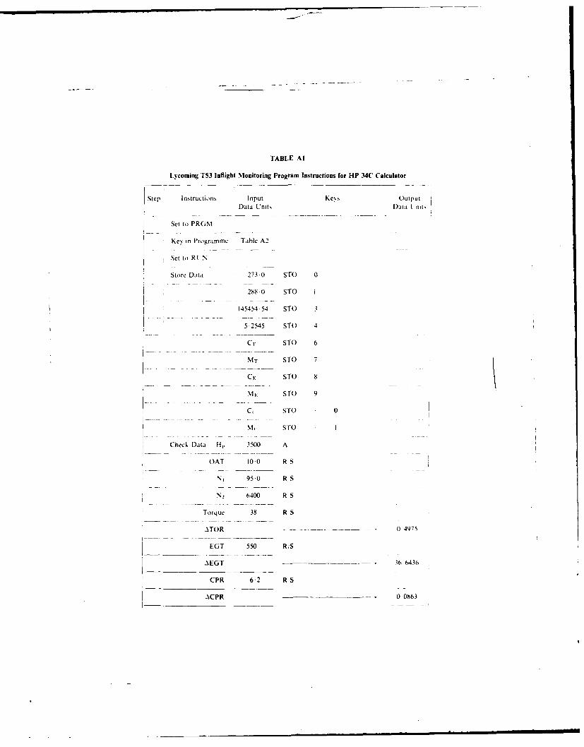
TABLE Al
Lycoming T53 Inflight Monitoring Program Instructions for HP .34C Calculator
Step Instructions Input Kess OutputData Units D~ata L nit,
Set to) PRIM
Kol in Prograrrm Table A2
Set it) R LN
Store Data 273 () STO 0
288) Sf0 I
45454 54 Sf0 3
5 2545 510 4
C1r Sf0 6
NIr Sf0 7
Cv Sf0 8
. 1. Sf0 9
C, Sf0 0
5010O
Check Data HI, 3500 A
OAT 100 R S
N1 95 0 R S
., 6400 R S
T orq ue 38 R S
.AT0R 0 04975
LGT 550 RS
AEGT - - -3664.36
CPR 6-2 RS
2.CPR 0 00863
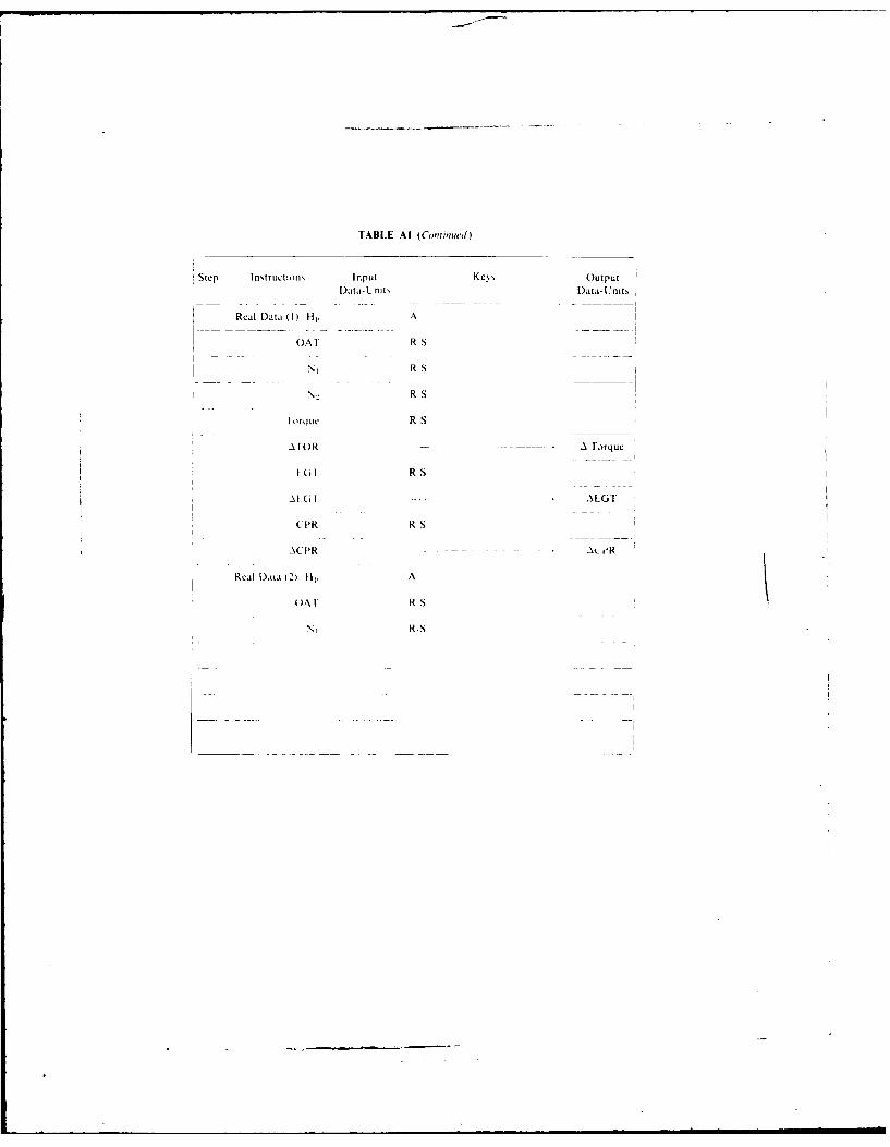
TABLE All (Continued)
Step Instructions~ Input Keys OutputlData-tL nits Data- Lnits
Real Data (1) Hl. A
()AI R S
R RS
R RS
I orq tc R S
AIOR -A lorque
[(R RS
A[61 - - - - ALGI'
CPR R S
A C PR A-i
Real Daja t2) 11;, A
OAI RIS
N RIS
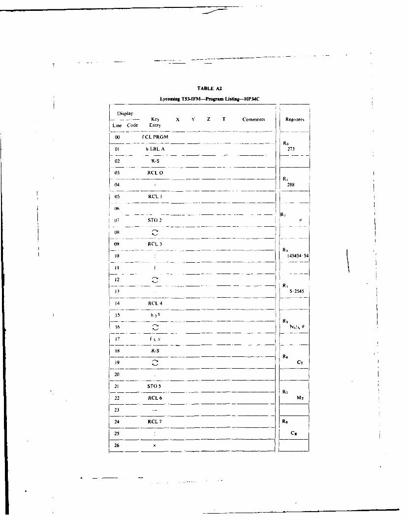
TABLE A2
Lycoming T53-IFM-Program Listing-HP34C
Display-- - Key X Y Z T Comments Registers
Line Code Entry
00 fCLPRGM( - - - - - - - R o
01 h LBL A 273
02 R,S
03 RCL O- - Ri
04 288
05 RCLI
06R
07 STO 2
08
09 RCL3
10 R3I 0 :145454.54
12R4
13 5.2545
14 RCL4
15 h yXRs
16 N
17 f N .
18 R/SR6
19 CT
20
21 STO 5Ri
22 RCL6 MT
23
24 RCL7 Re
25 C,
26 x
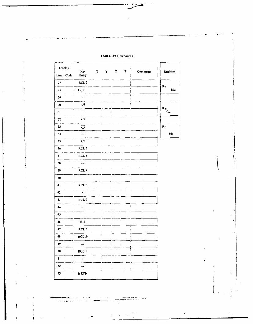
TABLE A2 (Continued)
DisplayKey X Y Z T Comments Registers
Line Code Entry
27 RCL 2R9
28 f x ME
29 x
30 R/SR.0
31 - C3
32 R/S
33 R.i
34 - Mc
35 R/S
36 RCL 5
37 RCL 8
38
39 RCL 9
40
41 RCL 2
42 x
43 RCL 0
44 -
45 -
46 R/S
47 RCL 5
48 RCL.0
49
50 RCL. I
52
53 h RTN
.. °.~

SHPC 0 T53-L13 N IC = .0128 SHPC + 83.51
1500 - T53-Ll 1 NIC .0225 SHPC + 74.5
1400
1300 -
1200 -
1100 -
1000 -
900
800 -
700
600
500
400 I I I I I70 75 80 8s 90 95 100 105
% NIC
FIG. Al SHAFT HORSE POWER vs ENGINE SPEED

_ _ _ _ T53-L13 NIC = .09434 EGTc(K) + 20.34
_ _ T53-L11 NIC = .10985 EGTc(K) +.03742
EGTc ° C
600 -
590 -
580 -
570 -
560 -
550 -
540 -
530 -
520 -
510 -
Soo -
490 -
480 -
470 -
460 -
450 -
440 -
430 -
420 -
410 -
400 I I I
70 75 80 85 90 95 100 105
% NIC
FIG. A2 EXHAUST GAS TEMPERATURE vs ENGINE SPEED

P3/p1
6.5 4- T53-L-13 Nic 17.3467 -p 10.2163P1
6.0
5.5
5.0
4.5
4 .3 .......... I70 7S 80 85 90 95 100 105
% NICFIG. A3 COMPRESSOR PRESSURE RATIO vs ENGINE SPEED

DISTRIBUTION
Copy No.
AUSTRALIA
Department of Defence
Central OfficeChief Defence Scientist IDeputy Chief Defence Scientist 2Superintendent, Science and Technology Programmes 3Aust. Defence Scientific and Technical Rep. (U.K.) -
Counsellor, Defence Science (U.S.A.) -
Defence Central Library 4Document Exchangt Centre, D.I.S.B. 5-21Director General--Army Development (NCO) 22-25Joint Intelligence Organisation 26
Aeronautical Research LaboratoriesChief Superintendent 27Library 28Superintendent Mechanical Engineering 29Divisional File-Mech. Engineering 30
Author: D. E. Glenny 31
Materials Research LaboratoriesLibrary 32
Defence Research CentreLibrary 33
Central Studies EstablishmentInformation Centre 34
RAN Research LaboratoryLibrary 35
Victorian Regional OfficeLibrary 36
Navy OfficeNaval Scientific Adviser 37RAN Air Maintenance and Flight Trials Unit 38Directorate of Naval Engineering 39Directorate of Naval Aviation Policy 40Directorate of Naval Ship Design 41
Army OfficeArmy Scientific Adviser 42Royal Military College Library 43US Army Standardisation Group 44
Air Force OfficeAircraft Research and Development Unit, Scientific Flight Group 45Air Force Scientific Adviser 46

Technical Division Library 47Director General Aircraft Engineering 484D~irector General Operational Requirements 49[IQ Operational Command [SENOSO] 50HQ Support Command [SENGSOJ 51RAAF AcademN. Point Cook 52
Department of Industry and CommerceGovernment Aircraft Factories
Manager 53LibrarN 54
Department of tfransportLibrars 55[Is in& Opcration, ind Airwsorthiness Dis ion 56'
Statutor~ and State Authorities and IndustryQantat,. Chief Aircraft Esaluation EngineerI ranv-Austral ,a Airlines. Librars, 5K
Ansctt Ai\rline, of Australia, LibrarN 59Common%%ealth Aircraft Corporation, Library 60Rolls Ro~ce of Aus.tralia PtN Ltd. 61Haw ker dle Havilland Pty Ltd.
Librarian. Bankstossn 612Manager. Bankstossn 631
U.niversities and CollegesS'.dnc Engineering Library 64R. M.1. T. Library 615
CANADAInternational Cns As iation Organization. Library 66NRC
Acronautical and Mechanical Engineering Library 67Dis son of Mechanical Engineering. Director 68
FRANCEONERA. Library 69
INDIADefence Minitr. Aero Development Establishment. Library 70Gas Turbine Research Establishment. Director 71Hindustan Aeronautics Ltd.. Librarv 72National Aeronautical Laboratory, Information Centre 73
NETHERLANDSNational Aerospace Laboratory [NLR]. Library 7
NEW ZEALANDDefence Scientific Establishment. Library 75Transport Ministry. Airwsorthiness Branch. Library 76
SWEDENAeronautical Research Institute, Library 77
UNITED KINGDOMCAARC. Secretary (NPL) 78Royal Aircraft Establishment:
Bedford, Library 79National Gas Turbine Establishment
Director, Pyestock North 80British Library, Lending Division 81Aircraft Research Association, Library 82GEC Gas Turbines Ltd.. Managing Director 83Rolls-Royce Ltd.:
Aero Division Bristol. Library 84Aero Division Leavesden. Library 85Westland Helicopters 86
Universities and CollegesCambridge Library. Engineering Department 87Cranfield Inst. of
Technology Library 88
UNITED STATES OF AMERICAN.A.S.A. Scientific and Technical Information Facility 89AVCO Corp.. AVCO Lycoming Division 90Bell Helicopter Textron 91
Spares 92-101
a3WI.4