Engine Block Casting
39
Engine block casting High performance, state of the art, engines are driven by the objective to reduce fuel consumption and exhaust gas emissions. This goal, however, is to be achieved while maintaining economic success (i.e. cost reduction).Countless measures that involved a great deal of development effort were developed and implemented in series production by manufacturers with support from the automotive suppliers. In general, a distinction can be made between external and internal engine modifications. The continuous introduction of exhaust gas after treatment in the vehicle by means of a catalyst or diesel particulate filter is an important measure for improving exhaust gas emissions. Intelligent control loops, such as the automatic start-stop system and the partial cylinder shutoff of a twelve-cylinder engine in the premium category, are very much in line with the trend. Internal engine modifications can generate a change of the crankcase, from which changed requirements for the production method of the foundry as the automobile manufacturer’s supplier are derived. Since the crankcase is the largest engine component, there is a strong focus on it with regard to reducing consumption by means of weight saving. The rule of thumb is: If the mass of the passenger car is reduced by 100 kg, the fuel consumption decreases by 0.3 liters per 100 km. The material development of a crankcase is therefore of great importance. The material characteristics of density and dynamic strength are major influence factors for the component mass. Cast iron as a material for crankcases is relatively outdated. However, the series production of crankcases made of aluminum alloys, which started at a much later point in time, represents a turning point for the passenger car. In principle, the crucial disadvantage of standard version cast iron as compared to aluminum is its higher density of 7.2 g/cm³. Crankcases for trucks are generally made of cast iron to this day. The two materials are currently competing to be selected as the material for the crankcase of large series passenger cars. A subsequent turning point has become known as "downsizing." Downsizing involves replacing large-volume engines with engines that have a smaller cubic capacity but at least the same power. It is possible to reduce fuel and exhaust gas by having more power with the same engine weight or more power with the same cubic capacity. The power-to-weight ratio and the power output per liter are therefore the characteristic values for downsizing. These values are improved by means of engine supercharging. A gradual evolution from the naturally aspirated engine to supercharging and twin-charging can be noted. The associated units are the supercharger and the turbocharger. For an appropriate vehicle, a high- performance 4-cylinder in-line engine with twin-charging represents an alternative to a naturally
-
Upload
amjad-pervaz -
Category
Documents
-
view
50 -
download
2
description
Engine block casting
Transcript of Engine Block Casting
Engine block castingHigh performance, state of the art, engines are driven by the objective to reduce fuel consumption and exhaust gas emissions. This goal,
however, is to be achieved while maintaining economic success (i.e. cost reduction).Countless measures that involved a great deal of
development effort were developed and implemented in series production by manufacturers with support from the automotive suppliers.
In general, a distinction can be made between external and internal engine modifications. The continuous introduction of exhaust gas after
treatment in the vehicle by means of a catalyst or diesel particulate filter is an important measure for improving exhaust gas emissions.
Intelligent control loops, such as the automatic start-stop system and the partial cylinder shutoff of a twelve-cylinder engine in the premium
category, are very much in line with the trend. Internal engine modifications can generate a change of the crankcase, from which changed
requirements for the production method of the foundry as the automobile manufacturer’s supplier are derived.
Since the crankcase is the largest engine component, there is a strong focus on it with regard to reducing consumption by means of weight
saving. The rule of thumb is: If the mass of the passenger car is reduced by 100 kg, the fuel consumption decreases by 0.3 liters per 100 km.
The material development of a crankcase is therefore of great importance. The material characteristics of density and dynamic strength are
major influence factors for the component mass. Cast iron as a material for crankcases is relatively outdated.
However, the series production of crankcases made of aluminum alloys, which started at a much later point in time, represents a turning
point for the passenger car. In principle, the crucial disadvantage of standard version cast iron as compared to aluminum is its higher density
of 7.2 g/cm³. Crankcases for trucks are generally made of cast iron to this day. The two materials are currently competing to be selected as
the material for the crankcase of large series passenger cars.
A subsequent turning point has become known as "downsizing." Downsizing involves replacing large-volume engines with engines that have
a smaller cubic capacity but at least the same power. It is possible to reduce fuel and exhaust gas by having more power with the same
engine weight or more power with the same cubic capacity. The power-to-weight ratio and the power output per liter are therefore the
characteristic values for downsizing. These values are improved by means of engine supercharging.
A gradual evolution from the naturally aspirated engine to supercharging and twin-charging can be noted. The associated units are the
supercharger and the turbocharger. For an appropriate vehicle, a high-performance 4-cylinder in-line engine with twin-charging represents
an alternative to a naturally aspirated 6-cylinder engine. This is also referred to as cylinder downsizing. One fewer cylinder means less
friction, a smaller crankcase, a smaller cylinder head, fewer bearing caps, etc., and as a result, less total weight. In general, increasing the
ignition pressure by means of supercharging increases the load on the crankcase. In order to compensate this, the dimensions of the walls
would have to be thicker. However, thicker walls mean an increase in weight and higher fuel consumption. Materials with increased strength
are in demand, since their use does not lead to a loss of the advantage of supercharging. Downsizing has thus broadened its restricted view
of density to include material strength. This is a large field of work for the development in the foundry and its suppliers. ASK, too, contributes
to this: The development work on increasing strength by means of improved heat dissipation through the mold material. In addition to the
chemical composition of the material, the component strength is also determined by the thermophysical properties of the mold material.
New approaches in lightweight design development
Crankcase hybrid made of a complex cast iron structure and aluminum alloy (Gießerei Halberg Guss together with VAW mandl & berger)
Crankcase hybrid made of aluminum alloy and magnesium alloy (BMW AG, Gießerei Landshut)
Low-density cast iron - < 6.8 g/cm³ (Gießerei Halberg Guss)
System solutions in engine block casting
The surface topology of the cylinder barrels, threads, very thin oil ducts and areas with very small dimensional tolerances cannot be achieved
in a single production step in casting. Mechanical processing is used for this, but near-net-shape casting is a crucial requirement for the
casting type so that the processing costs can be kept to a minimum. Standardized casting tolerances, which also depend on the casting
method, form the basis.
Flexibility of the size: All dimensions of crankcases can be produced using the sandcasting method; from the small 3-cylinder crankcase for
passenger cars to the largest crankcase for trucks.
Flexibility of the geometry: The freedom of design for the cavities in the crankcase is much higher as compared to the pressure die-casting
method.
Flexibility of time: Changes to the geometry and also prototypes can be implemented much quicker and in a more cost-effective way as
compared to the die-casting method.
When considering the entire production, the "birth" of the crankcase begins with the primary molding process of casting. A distinction is made
between casting into a metallic permanent mold and into expendable molds. Casting into expendable molds made of bound sand –
sandcasting – is widely spread in the production of crankcases, as it is the casting method that unites the highest level of flexibility with
excellent economic efficiency.
The molding base material and the binder are of great importance in the sandcasting method. The naming was also adapted due to this
great importance. In the core package method, the entire geometry is represented by sand cores. The surface of the core is coated
depending on the viscosity behavior of the melt, the pressure of the melt, the filling rates, and the casting temperature range. Coatings, a
dispersion of refractory particles and water, are used for molten cast iron, whereas a powdery core coating is applied for molten aluminum.
In the molding sand method, at least one main contour is represented by bentonite-bound sand. However, this can also involve cavities with
undercuts for auxiliary and ancillary equipment, such as a water-pump housing, due to additional cores that were introduced into the
bentonite-bound mold. Both casting types can be found in the cast iron area.
The dominant method for making crankcases out of aluminum alloys is the core package method. Increased hydrogen content in molten
aluminum causes casting defects. The mold heats up due to the melt cooling off. The binder it contains is heated up and emits gas that finds
its way through the mold material’s porous body to the boundary between the mold and the melt. If the gas contains hydrogen, it can find its
way across the boundary and into the mold. Since molten aluminum is sensitive to hydrogen, one requirement for the binder is that it should
not emit gases that contain hydrogen. As water vapor is released when using bentonite-bonded molds, the core package method is used for
molten aluminum as a precaution.
Besides the technical requirements, such as sufficient mold strength and resistance against abrasion, requirements for environmental
protection are increasingly pushing themselves to the forefront. Gas emissions should be more environmentally friendly in terms of their
composition, amount and odor. ASK Chemicals has defined the milestones of developing highly reactive binders and inorganic binders.
As the following examples demonstrate, the first rough parameters for the casting process emerge from the features listed above, i.e. design,
cubic capacity, number of cylinders, number of cylinder banks, angle of the cylinder banks, "open deck" or "closed deck." V-engines with a
90° cylinder bank angle always require the core package method. The problem of undercuts that otherwise occurs is solved by a "heart core"
in the core package, which represents the gap between the cylinder banks. In contrast to this, a 6-cylinder V-engine with an extremely
narrow angle between the cylinder banks can be cast horizontally using cast iron and without a core package since this design does not
involve cavities between the cylinder banks. The relation between the cubic capacity and the size of the mold shall serve as the third
example: Appropriately large mold boxes and tools are necessary for producing cores for a truck crankcase for a V-engine with a 12-liter
cubic capacity. Four crankcases for a 1.4-liter passenger car engine could be cast simultaneously in the same mold box.
The rough parameters of the casting process include the casting position. If the cylinder barrels are largely parallel to the horizontal mold
partition, the casting position is referred to as horizontal. If the cylinder barrels are at an angle of 90° to the horizontal mold partition, the
casting position is referred to as vertical. A vertical casting position is only possible with the core package method.
Requirements for the material
The crankcase takes on a local complex load that must be born reliably for several hundred thousand kilometers and many years. This
results from the complex of loads that act on the component and that are composed of gas forces in the combustion cycle, of reaction forces
in the power cycle and of bends and screw joints. There are also the interior forces from the thermal expansion, internal stresses, the weight
force of the component's own mass, the weight force of screwed on components, such as the crankshaft and the cylinder head, and the
forces from the thermal expansion of the add-on parts that are transmitted via the screw connection.
The highest thermal stress is usually found in the web area of the cover plate. The fact that water and lubricants are routed through the
component poses the requirement of pressure tightness, cleanliness and permeability of the liquid-carrying ducts in the crankcase. As a
consequence of the task of piston guidance, the cylinder barrel must be part of a tribology system. This is the cylinder barrel/lubricant/piston
ring system. The surface film of the cylinder barrel must therefore display tribologically appropriate properties. Low friction loss, wear and
tear, and lubricant consumption are the goals.
The requirements for the material are derived from the loading cases, the production operations of the automobile manufacturer and the
environmental aspects:
CO2 equivalent of material production – low
Machinability – high
Fatigue strength under reversed bending stresses – high
Fatigue strength under alternating stresses at operating temperature – high
Density – low
Pressure tightness – high
Compression strength – high
Damping of natural vibration – high
Elasticity modulus – high
Tolerable surface pressure – high
Overall cost of the production process – low
Corrosion resistance – high
Creep resistance – high
Shrink hole tendency and inclusion tendency – low
Recyclability – high
Thermal expansion coefficient – as similar to the crankshaft material as possible
Wear resistance – high
Thermal conductivity – high
There is no material that fulfills the aforementioned requirements 100%. Aluminum alloys and cast iron alloys are therefore competing
against each other, and this competition is increased due to ever new approaches in lightweight design development.
Typical casting defects and suitable remedial action
Here are some characteristic examples to highlight this:
Problems in the area of the cylinder ridge can occur when designing a crankcase to achieve smaller gaps between cylinders. Undesired
cavities are exposed after the cylinder barrel has been processed. In the case of horizontal casting, this occurs predominantly at the level of
the core clasp of the water jacket. In combination with an unfavorable flow of the melt, the core clasp probably acts as a formation aid and
obstacle for the gas bubble, which is made of core gases or entrapped air from mold filling. A solution would be to define a premature
concept regarding the position and type of core clasps as early as the product development stage. The question is whether it is possible to
move the core clasp downward in the cylinder barrel, so that the position of the defect is below the critical piston travel zone. A further
question would be whether it would be possible to introduce the core package method in a vertical casting position during the development
phase of the component. Core clasps in the water jacket are not necessary for this casting position. A further advantage of the core package
method is that it can be easily traced due to the automated labeling of the core, which is transmitted to the cast part. Process monitoring and
the analysis of the causes of the cast defect can be done at a deeper and broader level in the core production parameters. However, it must
be checked whether the uncontrolled seepage is restrained in the area of the cast iron in the core package method.
Typical casting defects found in ducts are:
The duct is not sufficiently permeable
The residual dirt content is too high
The oil duct and water jacket are not sufficiently pressure-tight
The undesired deviation in shape in the form of veining in oil ducts can range from limited permeability that is no longer tolerable to complete
closure. Oil ducts twisted in increasingly complex fashions are the trend in downsizing, so that it is becoming increasingly difficult to check
and rework the ducts in the casting cleaning room. Suitable remedial action includes changing the characteristics of the grain for the core,
additives and also adapted coatings.
The casting process is not completed after solidification. The boxing-out process and the removal of the core should not be underestimated.
For example, openings may become necessary for removing the sand in the case of very thin and deep water jackets. They are closed with
sheet-metal covers in a further production step after mechanical processing. The size of the openings in the cover plate should also be
questioned when the concept is drawn up, in order to take core removal capability into account in the design. Core removal capability in
particular is an important area of development in the binder system. This is accompanied by compliance with the amount of residual dirt. The
amount of residual dirt refers to the percentage of material from the completed primary molding process that remains in the cavities of the
metal body after it has passed through the full process. Loose particles of residual dirt could find their way into the oil while the engine is
running and, in the worst case, very large particles could reduce the bearing life. 500 mg are therefore required for a crankcase for a 2.0-liter
passenger car as a precaution. ASK Chemicals makes a contribution in the form of coatings with a reduced formation of compounds that are
developed together with the respective foundry.
Analyzing the causes is important for defining remedial action. For this, ASK Chemicals has its own in-house simulation software as a tool.
Solidification simulation is available for analyzing the causes of shrink holes. But what about casting defects caused by gas bubbles? ASK
Chemicals is doing intensive pioneering work on this issue. The milestone here is to introduce appropriate simulation software that provides
orientation for questions concerning the amount of gas that forms locally and the local gas pressure at the boundary. Furthermore, the
development toward highly reactive binder systems should be mentioned. Due to the high reactivity, the required amount of binders
decreases, and a lower binder content means less gas pressure at the boundary between the mold and the melt. A decision aid provided by
the simulation tools and the favorable conditions of a modern binder system takes the place of coincidence. If these are applied early on in
the product development phase, they can help to prevent the defect from being carried over into the later phases. The later the defect is
eliminated, the greater the economic damage that is caused.
The surface topology of the cylinder barrels, threads, very thin oil ducts and areas with very small dimensional tolerances cannot be achieved
in a single production step in casting. Mechanical processing is used for this, but near-net-shape casting is a crucial requirement for the
casting type so that the processing costs can be kept to a minimum. Standardized casting tolerances, which also depend on the casting
method, form the basis.Requirement for the mold, the core, the material, and the casting type
The quality management of the foundry provides data on internal, externally detected, obvious and hidden casting defects for the crankcase.
In general, undesired cavities and undesired deviations in shape that prevent the component from functioning reliably are considered to be
defects. The focus in the sandcasting method is on the function groups of the cylinder barrel, the oil duct and the water jacket. Saving
material by means of downsizing and reducing the engine installation space results in increasing requirements for the foundries.Two
explanations are often used to analyze the causes of undesired cavities, and these explanations are summarized here in strongly simplified
terms. First, there is the undesired cavity caused by shrinkage, the shrink hole, which is a result of the volume deficit that occurs during the
transition from the liquid aggregation state to the firm aggregation state of a metal. The second undesired cavity is the gas bubble that is
trapped during solidification and surrounded by the metal. The mold heats up due to the melt cooling off. The binder it contains is heated up
and emits gas that finds its way through the mold material's porous body to the boundary between the mold and the melt. If the pressure of
the gases is high enough, they can find their way into the melt and turn into a gas bubble. In practice, there are many transitional forms
between shrink holes and gas bubbles.
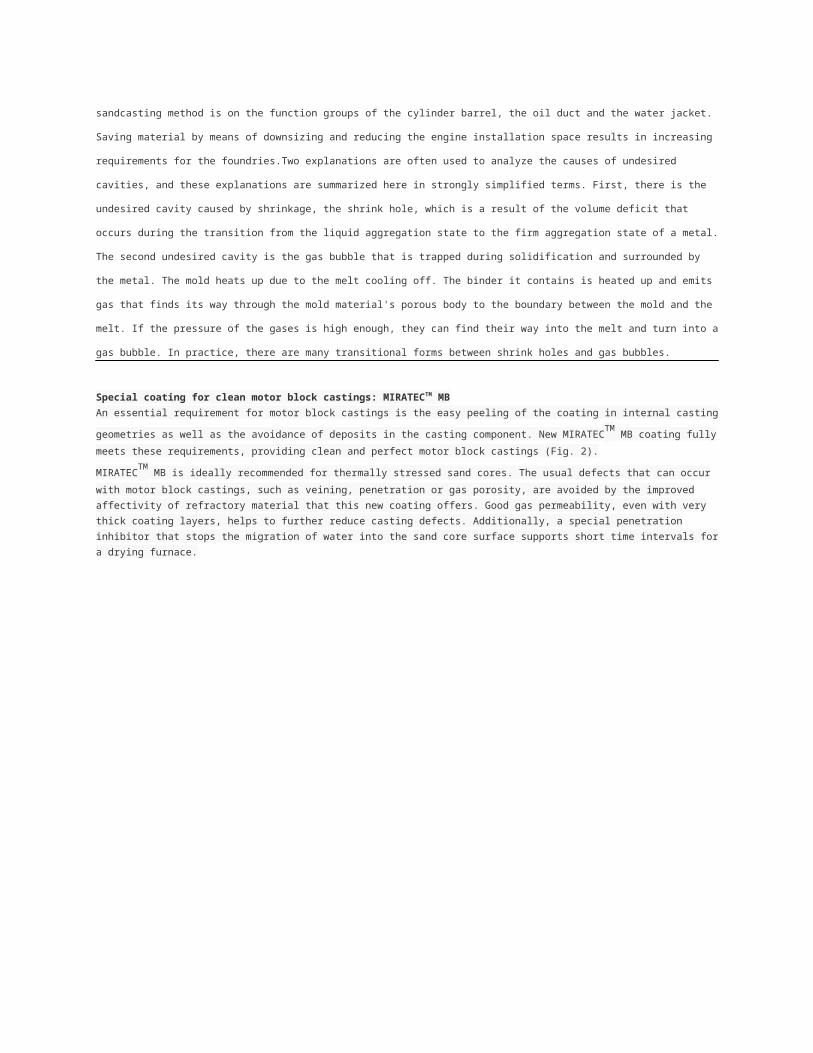
Special coating for clean motor block castings: MIRATECTM MBAn essential requirement for motor block castings is the easy peeling of the coating in internal casting geometries as well as the avoidance of
deposits in the casting component. New MIRATECTM
MB coating fully meets these requirements, providing clean and perfect motor block
castings (Fig. 2).
MIRATECTM
MB is ideally recommended for thermally stressed sand cores. The usual defects that can occur with motor block castings,
such as veining, penetration or gas porosity, are avoided by the improved affectivity of refractory material that this new coating offers. Good gas permeability, even with very thick coating layers, helps to further reduce casting defects. Additionally, a special penetration inhibitor that stops the migration of water into the sand core surface supports short time intervals for a drying furnace.
Casting Defect PreventionPenetrations: Defect Pattern & CausesFundamental causes for real (mechanical/physical) penetration are metallostatic pressure, dynamic pressure during casting, and
crystallization pressure during solidification.
Possible formation mechanisms
Sand molds display a certain pore system that corresponds to their packing density. At the boundary between the metal and the mold
material, there is a balance between the metallostatic pressure, the capillary forces of the mold material, the wettability and the surface
tension of the metal. When the melt meets the grains of the mold surface during casting, it can penetrate into the pores of the mold surface
under the effect of the metallostatic pressure until a balance between the interfacial tension at the mold surface and the penetration pressure
(critical pressure value at which the melt penetrates through the topmost layer of grains) has been reached. As a result of this, the surface of
the cast piece is rough.
The interfacial tension, which counteracts the penetration pressure, is influenced by the capillary forces of the mold material (primarily by the
porosity), by the wettability of the mold surface and by the surface tension. The interfacial tension of casting materials on an Fe-C basis
reaches relatively high values. The extent of this tension is influenced primarily by the chemical composition of the main alloying elements
and the presence of surface-active elements, such as bismuth, lead, phosphorous, silicon and others. Adding cerium, sodium and zircon also
increases the interfacial tension.
The melt wets the sand structure of the mold surface and displays it with varying intensity (roughness, wetting depth). The larger the
penetration pressure, the grain radius of the mold material, the radius of its pores and the density of the grains are, and the smaller the
interfacial tensions are, the higher the values are that are reached by the wetting depth. The wetting angle and therefore the wettability of a
mold surface can be significantly influenced by the formation of a layer of lustrous carbon.
The size of the pore radius of a compacted mold part depends primarily on the grain structure (grain size, grain particle size distribution), the
additions (proportion of binder, sediments), the intensity of compaction (packing density), and the sintering behavior of the mold material.
We use the term penetration when the roughness depth is larger than or equal to the radius of the grains of the mold material. This means
that it is only possible to draw a line between roughness and penetration under consideration of the grain size of the mold material.
Penetration can thus occur as a function of the following influence factors:
The grain size of the mold material is too large and the grain particle size distribution is too broad
The proportions of binder and sediment are too small
The proportion of materials that form lustrous carbon is too low
Unfavorable chemical composition of the casting material in combination with casting temperatures and metallostatic pressure that are too
high
Inadequate and uneven compaction of the molds or cores
Inadequate gating system and therefore excessive overheating of molds and core components
Defect PreventionPenetrations occur in all cast parts that are produced with the sand molding method, regardless of the material. A number of measures have
proven effective in the prevention of penetration and the most important ones are listed below:
Using finer sands or refining the grain size of the sand in the return sand through the inflow of fine-grained (core) sands. Adding additives to
core sands
Increasing the additions that form lustrous carbon. The carbon softens under the effect of the casting heat and forms a protective film; the
wettability is reduced
Increasing the proportions of binder and sediment, reducing the compactibility of the mold material system, which causes an increase of the
sand's flowability and enables better compaction
Coating at least the mold and core components that are at risk; this significantly reduces the porous space immediately at the surface of the
mold/core
Avoiding surface-active elements in the chemical composition of the material as far as possible, for example phosphorous and lead
Reducing the metallostatic pressure and improving the gating system to the effect that casting bursts and strong overheating of the mold and
core components are prevented
Reducing the casting temperature
Using suitable coatings
Product solutionsIn the case that a chemical reaction takes place between the penetrating metal and the mold material, we describe this as burning, sintering,
or usually metallization. It is thus only possible to draw a line between roughness and penetration under consideration of the grain size of the
mold material.
ASK Chemicals offers the following support and solutions with regard to products and expertise:
Creating complete mold material analyses (for example grain size, grain particle size distribution, proportion of sediment, sintering behavior,
etc.) and creating assessments of mold materials
Highly effective materials that form lustrous carbon as well as mixtures of bentonite and GKB
Bentonites that require a small amount of water for dispersion and exhibit high thermal resistance
Highly effective additives for the core molding material
Effective water- and alcohol-based coatings by using appropriate refractory base materials
Transferring expertise to improve the gating system to the effect that casting bursts and strong overheating of the mold and core components
are prevented and to achieve better dissipation of casting gases that contain water vapor from the mold and improved core venting.
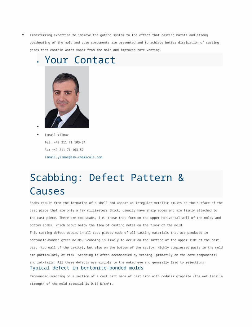
Your Contact
Ismail Yilmaz
Tel. +49 211 71 103-34
Fax +49 211 71 103-57
Scabbing: Defect Pattern & CausesScabs result from the formation of a shell and appear as irregular metallic crusts on the surface of the cast piece that are only a few
millimeters thick, usually have sharp edges and are firmly attached to the cast piece. There are top scabs, i.e. those that form on the upper
horizontal wall of the mold, and bottom scabs, which occur below the flow of casting metal on the floor of the mold.
This casting defect occurs in all cast pieces made of all casting materials that are produced in bentonite-bonded green molds. Scabbing is
likely to occur on the surface of the upper side of the cast part (top wall of the cavity), but also on the bottom of the cavity. Highly compressed
parts in the mold are particularly at risk. Scabbing is often accompanied by veining (primarily on the core components) and rat-tails. All these
defects are visible to the naked eye and generally lead to rejections.
Typical defect in bentonite-bonded molds
Pronounced scabbing on a section of a cast part made of cast iron with nodular graphite (the wet tensile strength of the mold material is 0.16
N/cm²).
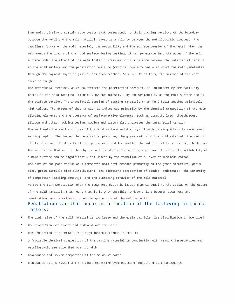
Rat-tails
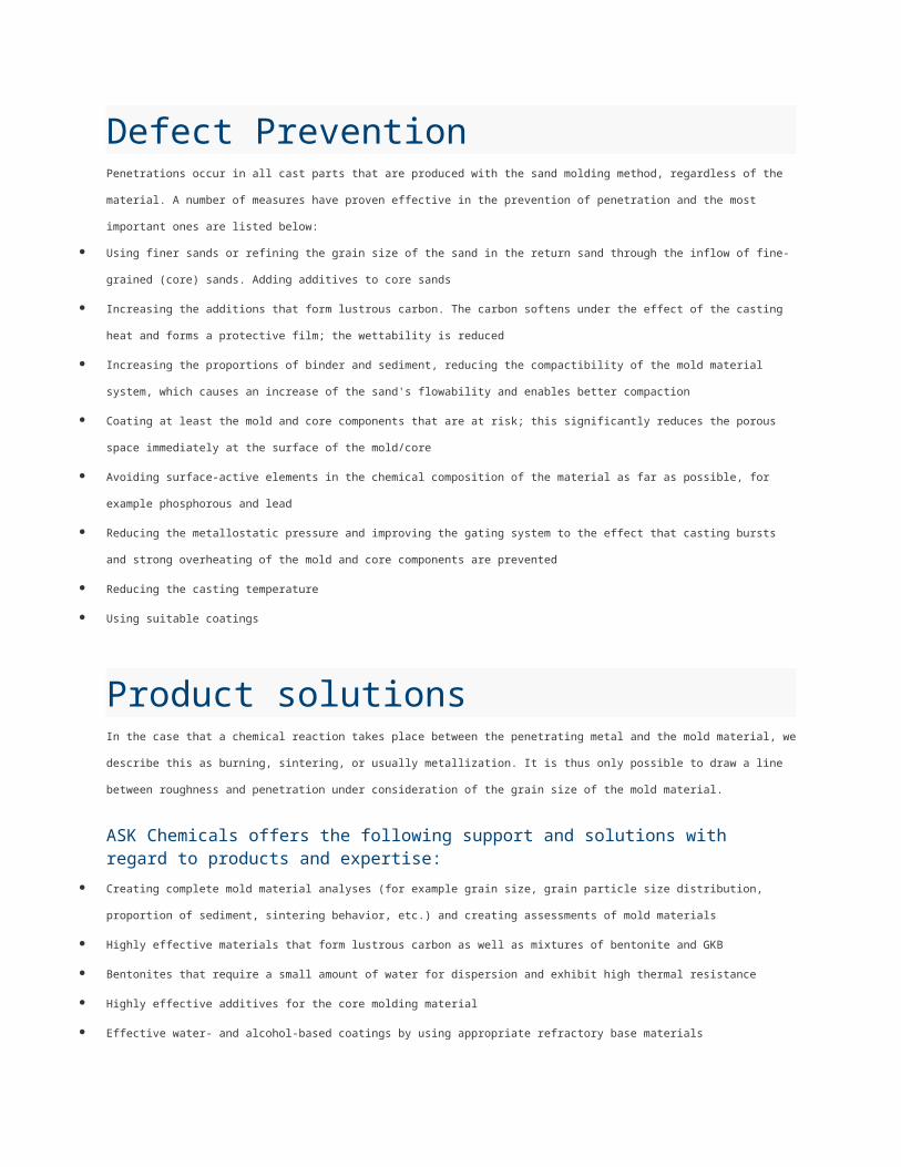
Areas of sand expansion, in this case scabbing and rat-tails, can be combated successfully by increasing the wet tensile strength. Defects
are clearly prevented by increasing the wet tensile strength (N/cm²) (see values below the figures).
Veining also forms as a result of the formation of a shell; however, this shell does not break open but grows into the mold cavities as a result
of the silica expanding, which causes the casting metal to fill in the resulting gap and form a vein-like crust. Veining is very frequently
observed in synthetic resin-bonded cores (also commonly referred to as scabbing).
Causes
The influence of heat (radiation, thermal conduction) from the casting metal causes a thermal expansion of the mold material. Considerable
differences in stress occur as a result of the different temperatures in the individual zones of the mold. This stress influences the surface
layers of the mold or the walls of the mold.
Compression stress versus tensile strength
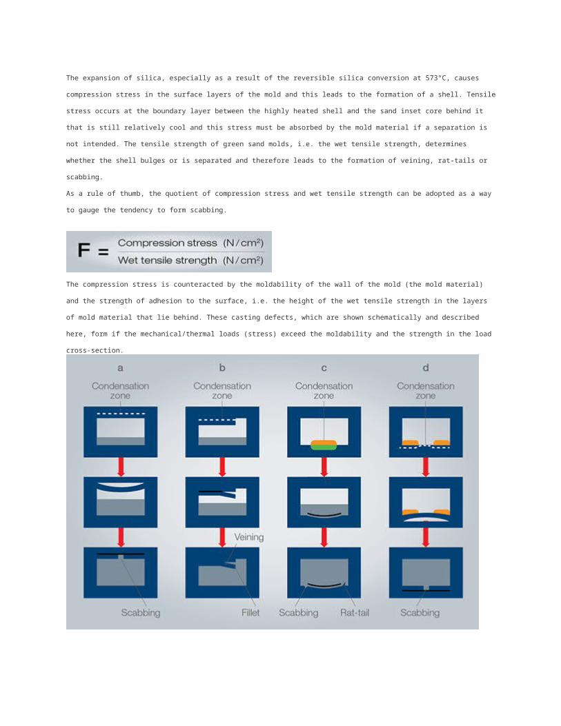
The expansion of silica, especially as a result of the reversible silica conversion at 573°C, causes compression stress in the surface layers of
the mold and this leads to the formation of a shell. Tensile stress occurs at the boundary layer between the highly heated shell and the sand
inset core behind it that is still relatively cool and this stress must be absorbed by the mold material if a separation is not intended. The
tensile strength of green sand molds, i.e. the wet tensile strength, determines whether the shell bulges or is separated and therefore leads to
the formation of veining, rat-tails or scabbing.
As a rule of thumb, the quotient of compression stress and wet tensile strength can be adopted as a way to gauge the tendency to form
scabbing.
The compression stress is counteracted by the moldability of the wall of the mold (the mold material) and the strength of adhesion to the
surface, i.e. the height of the wet tensile strength in the layers of mold material that lie behind. These casting defects, which are shown
schematically and described here, form if the mechanical/thermal loads (stress) exceed the moldability and the strength in the load cross-
section.
Top scabs thus develop from the condensation zone in the mold surface as a result of the compression stress that occurs there and that
pushes up the wall of the mold and lifts it off (a). This process is generally referred to as shell formation. Veining is also caused by the
formation of a shell (b). However, the shell does not break open, so that a burr-like elevated seam becomes visible on the cast part. This
veining can be removed by means of increased cleaning work, and the cast part can possibly be saved. Bottom scabs form in the mold cavity
below a flow of casting metal and thus on the bottom of the mold. The condensation zone that effects the formation of a shell is the cause
here, too. If the sand shell remains attached to the bottom of the mold, the protruding edges of the shell cause either scabbing or rat-tails (c).
In contrast, if the sand shell bulges and breaks apart under the weight of the metal that flows across it, a typical bottom scab forms at the
underside of the cast piece (d).
Defect preventionIncreasing the wet tensile strength of the molding material mixture through
A higher binder content (bentonite)
The use of better bentonites with a larger specific surface
The use of optimally activated bentonites
Excellent cooling of the mold material
A high releasing effect in the core box
Aiming at a better (optimum) preparation of the mold material
Selection of a courser sand grain size with a sand grain that is as round as possible
Reducing occurring compression stress through
Quick and even mold filling
Avoidance of mold materials that are too moist
The use of mold material additions that buffer the expansion of silica by means of softening or burning (e.g. neutral or basic swelling binders
for steel casting)
Partial or, if necessary, full replacement of the silica sand with refractory sands with a lower expansion, for example zircon sand or chromite
sand.
Product solutionsThese casting defects occur if the mechanical/thermal loads (stresses) exceed the moldability and the strength in the load cross-section. Scabbing then
appears as irregular metallic crusts on the surface of the cast piece that are only a few millimeters thick and that usually have sharp edges and rough
surfaces.
ASK Chemicals offers the following solutions with regard to products and expertise:
Optimally activated bentonites
Bentonite that is produced from multiple raw clay components and with an activation technique that is carefully coordinated to them in order
to improve the technical properties of the mold. With the appropriate preparation, this yields the best wet tensile strength in the mold material
mixture.
Bentonite-carbon mixtures that feature the highest mold strengths in addition to the uniformity in various states of production that is typical for
hybrid bentonites.
Carbons that absorb compression stress in the wall of the mold by means of softening and swelling, which reduces the formation of scabbing
Transferring expertise with regard to mold material preparation, control and checking
Special binders and additives for core production and therefore avoiding core scabbing
Optimum alcohol- and water-based coatings that are coordinated to the respective production range (molding base material, casting
material)
Metallizations: Defect Pattern & Causes Preferred locations where metallization occurs are edges in the mold or core where the metal remains liquid for a long time due to
the geometry of the cast piece and where the mold parts are strongly heated. This defect can occur in all cast parts that are
produced with the sand molding method (preferably with the green sand method), regardless of the material, as a result of
physical/chemical interaction between the melt and the components of the mold material.
Close connection between metallization and penetration
Melting phases that lead to burnt sand (sintering) and metallization (Figures 1 and 2) occur as a result of reactions between the
metal and the mold material. This defect occurs frequently when casting alloyed cast steel in particular. It is visible to the naked
eye on the cast part. Copper-tin and copper-zinc alloys are also at risk.
Figure 1: Cast part with heavy metallization Figure 2: Photo of metallization at the surface of the
cast piece taken with an optical microscope,
10:1 magnification.
In contrast to real physical/chemical penetration, metallization is a chemically caused penetration. If a thin sand crust made of
individual quartz grains that adheres firmly to the cast piece occurs, we use the term burnt sand (sintering). If this thin layer that
now adheres to the cast piece very firmly consists of melted sand and if the entire surface is also pimpled, we use the term
metallization (Figures 3 to 5).
Figure 3: The top parts of the cast pieces are clearly Figure 4: SEM photo of metallization on the surface
pimpled, 25:1 magnification. of the cast piece; the melted sand grains are clearly
visible
It is not possible to clearly distinguish between the defects of penetration and metallization. Metallization is always preceded by
penetration and sintering. In any case, the defect leads to significantly increased cleaning work, if not to rejections.
Causes
When metallization occurs, the wetting stress can be influenced in such a way that the penetration pressure (see penetration)
decreases under the present metallostatic pressure, which significantly intensifies the penetration on the cast part. On the other
hand, melting phases that lead to the formation of silicate layers (metallization) can occur as a result of reactions between the
metal and the mold material, with the atmospheric oxygen in the mold cavity and the pores of the mold material making a
significant contribution.
Influence factor
Both the silica sand and the disintegration products of the clay react with metal oxides (e.g. FeO) at higher temperatures and form
low-melting orthosilicates according to the following reaction scheme:
2Fe + O2 _ 2FeO
Al2 O3 · SiO2 + 4FeO _ 2(2FeO · SiO2) + Al2 O3

fayalite
The iron oxides that develop in this process wet the mold material much better than the metallic iron and this increases the
possibility of sintering and occurrences of burning. In general, the formation of intermediate layer phases can be expected during
reactions between the metal and the mold material. These phases behave differently depending on the composition of the
reaction partners with regard to wettability and reactivity. Preceding penetration of metal vapors increases the metallization
tendency. The manganese oxide slags that develop during the production of manganese steel are very aggressive and increase
the material's metallization tendency.
Defect preventionAn overview of the key measures for preventing metallization
In order to prevent defects, it is recommended to assess the sintering behavior of bentonite, the molding base material and mold material
mixtures by means of tests. The sintering behavior of these components should reach highest values in any case.
Molding sands should not exhibit any contamination that enables a reaction with the slag and the formation of low-melting slags.
Increasing the thermal stability of the mold material by adding new sand (to reduce oolitization); not using or adding any contaminated sands.
Using chemically neutral molding base materials; chromite sand, for example, has proven to be favorable to silica sand.
Carefully coating molds and cores; the occurrence of small cracks in the coating layer is to be avoided; possibly increasing the thickness of
the coating layer.
The formation of reactive oxides and slags should be prevented by adding a sufficient amount of components that form lustrous carbon.
All measures that help to prevent penetration also have a positive influence on the prevention of metallization.
Product solutionsIn general, metallization is always preceded by penetration. In addition to the edges, overheated areas of the mold and the core that are
poorly compacted are also at risk. Metallization can basically be prevented by mold material mixtures of sufficiently good quality with high
sintering behavior and appropriate coatings.
ASK Chemicals offers the following solutions with regard to products and expertise:
Bentonites with high thermal resistance for the green sand molding method
Additives for core production
Materials that form lustrous carbon and prevent the formation of highly reactive oxides and slags
Checking the sintering behavior of molding base materials, bentonites and mold material mixtures
Creating assessments of mold materials in combination with complete mold material checks
Highly effective and highly refractory alcohol- and water-based coatings, coordinated to the molding base material and the material
Transferring expertise to improve the gating system to the effect that casting bursts and strong overheating of the mold and core components
are prevented and to achieve better dissipation of casting gases that contain water vapor from the mold and improved core venting.
Shrink holes: Defect Pattern & Causes

The formation of shrink holes occurs in all technical casting materials, regardless of the mold or casting process. However, the
pressure die-casting technique provides possibilities for preventing or minimizing the formation of shrink holes by creating high
final pressure immediately after mold filling. This does not prevent gas porosity.
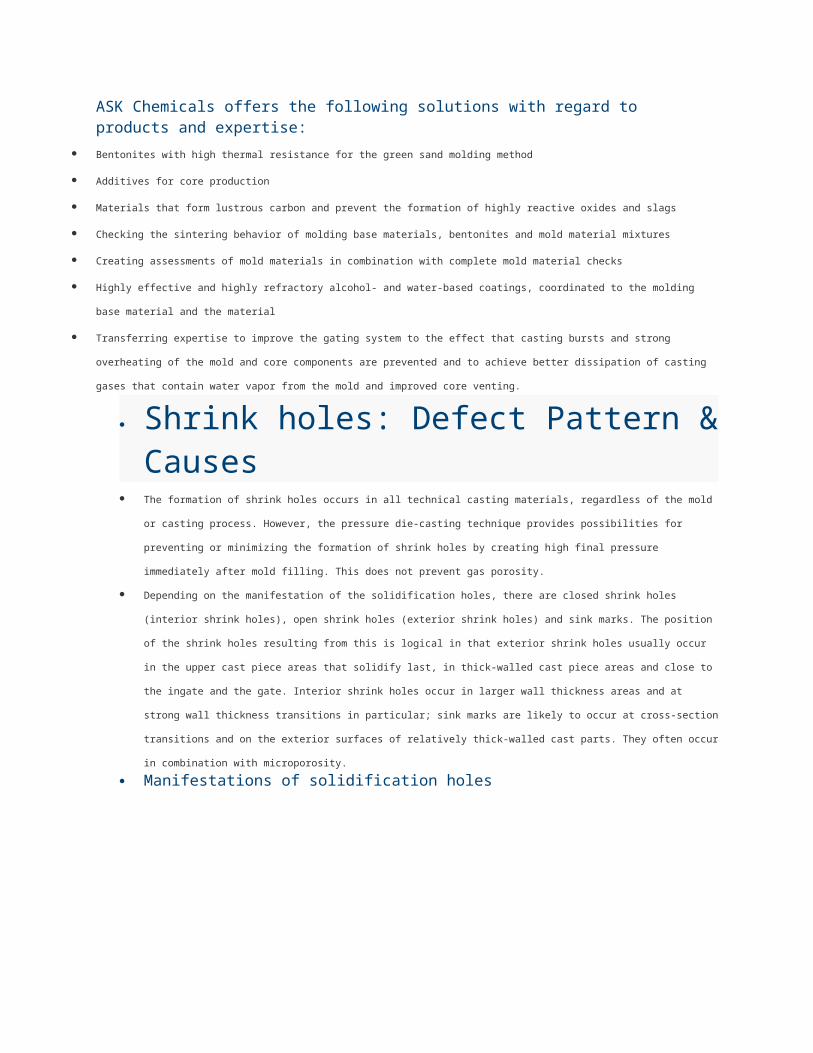
Depending on the manifestation of the solidification holes, there are closed shrink holes (interior shrink holes), open shrink holes
(exterior shrink holes) and sink marks. The position of the shrink holes resulting from this is logical in that exterior shrink holes
usually occur in the upper cast piece areas that solidify last, in thick-walled cast piece areas and close to the ingate and the gate.
Interior shrink holes occur in larger wall thickness areas and at strong wall thickness transitions in particular; sink marks are likely
to occur at cross-section transitions and on the exterior surfaces of relatively thick-walled cast parts. They often occur in
combination with microporosity.
Manifestations of solidification holes
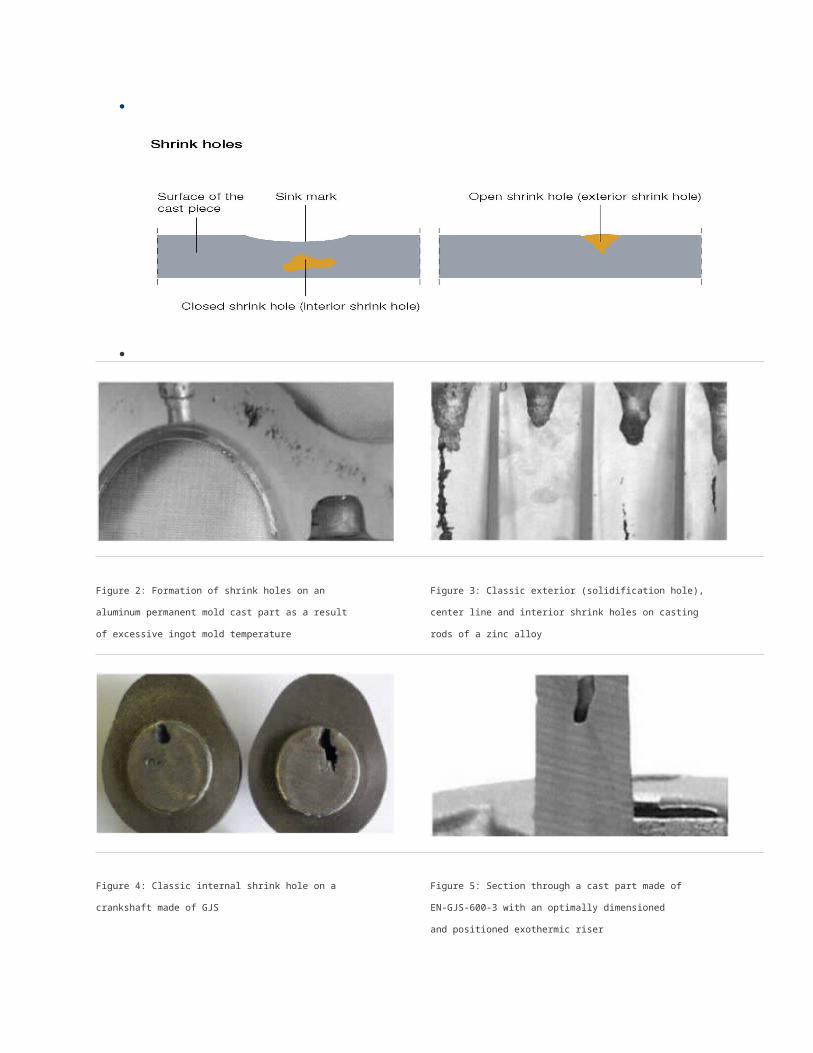
Figure 2: Formation of shrink holes on an
aluminum permanent mold cast part as a result
of excessive ingot mold temperature
Figure 3: Classic exterior (solidification hole),
center line and interior shrink holes on casting
rods of a zinc alloy
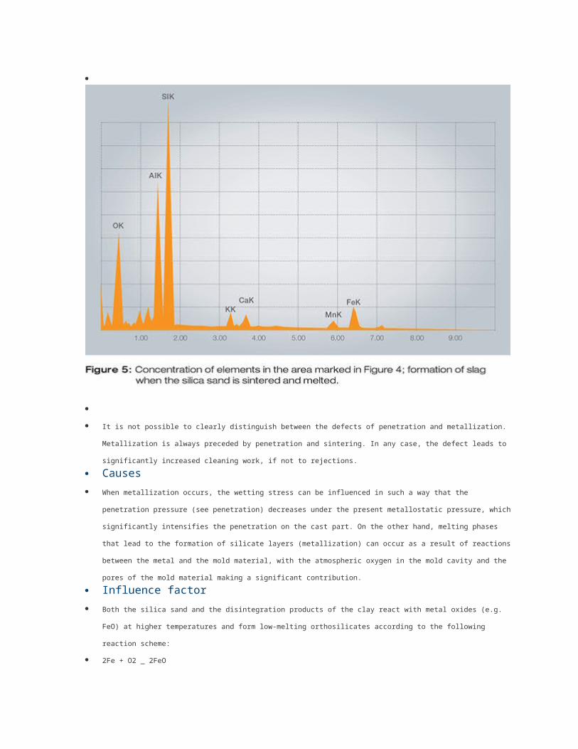
Figure 4: Classic internal shrink hole on a
crankshaft made of GJS
Figure 5: Section through a cast part made of
EN-GJS-600-3 with an optimally dimensioned
and positioned exothermic riser
Materials with small solidification intervals and smooth-wall solidification, such as pure metals and eutectic or peritectic alloys, are
particularly prone to solidification holes.
Solidification holes
(exterior shrink holes) are deep symmetrical cavities that generally have a funnel-shaped opening to the outside and sometimes
continue into the interior as closed cavities. The walls of the cavities are mostly rough and frequently dendritic. Exterior shrink
holes are clearly visible to the naked eye.
Interior shrink holes
have no connection to the outside and are thus located in the interior of the cast piece. Their shape is irregular and the walls are
rough and often covered with dendrites. They become visible to the naked eye during a nondestructive test or during processing
at the latest.
Sink marks are trough-shaped cavities in the surface of the cast piece that occur in the area of larger material accumulations. The
surface of the sink mark does not differ from the surface of the remaining cast piece. Sink marks are also visible to the naked eye.
If casting-related measures (directional solidification, feeding) do not succeed in shifting the shrink holes to areas outside the cast
piece, this casting defect leads to rejection.
Contraction of the casting metals during solidification and cooling
The specific volume of the standard casting metals is larger in the liquid state than in the solid state. For this reason, these metals
undergo contraction when solidifying and cooling. This leads to a volume deficit that manifests itself in the form of defects, such as
shrink holes, sink marks, microporosity, etc. Shrink holes are thus the result of the interaction between the physical volume deficit
during the solidification process and the possibility of compensating it through additional feeding.
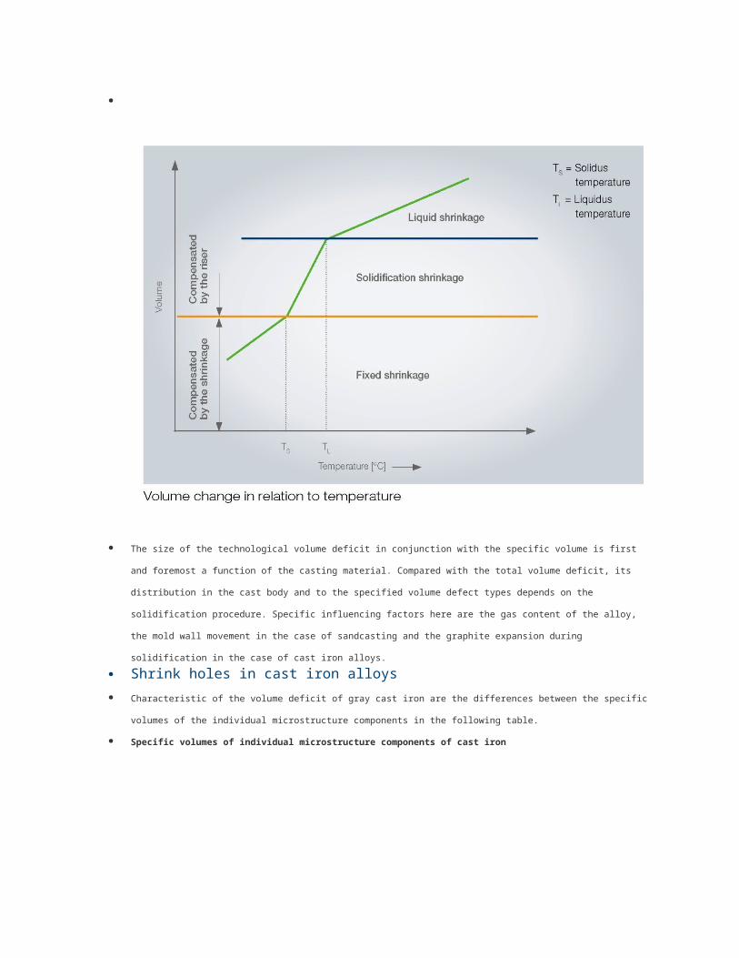
The size of the technological volume deficit in conjunction with the specific volume is first and foremost a function of the casting
material. Compared with the total volume deficit, its distribution in the cast body and to the specified volume defect types depends
on the solidification procedure. Specific influencing factors here are the gas content of the alloy, the mold wall movement in the
case of sandcasting and the graphite expansion during solidification in the case of cast iron alloys.
Shrink holes in cast iron alloys
Characteristic of the volume deficit of gray cast iron are the differences between the specific volumes of the individual
microstructure components in the following table.
Specific volumes of individual microstructure components of cast iron
Microstructure
component
Specific volume
in m3/g
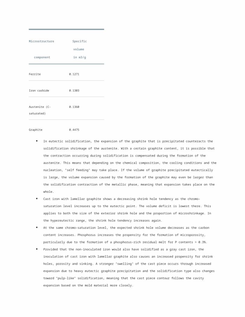
Ferrite 0.1271
Microstructure
component
Specific volume
in m3/g
Iron carbide 0.1303
Austenite (C-saturated) 0.1360
Graphite 0.4475
In eutectic solidification, the expansion of the graphite that is precipitated counteracts the solidification shrinkage of the austenite.
With a certain graphite content, it is possible that the contraction occurring during solidification is compensated during the
formation of the austenite. This means that depending on the chemical composition, the cooling conditions and the nucleation,
"self feeding" may take place. If the volume of graphite precipitated eutectically is large, the volume expansion caused by the
formation of the graphite may even be larger than the solidification contraction of the metallic phase, meaning that expansion
takes place on the whole.
Cast iron with lamellar graphite shows a decreasing shrink hole tendency as the chromo-saturation level increases up to the
eutectic point. The volume deficit is lowest there. This applies to both the size of the exterior shrink hole and the proportion of
microshrinkage. In the hypereutectic range, the shrink hole tendency increases again.
At the same chromo-saturation level, the expected shrink hole volume decreases as the carbon content increases. Phosphorus
increases the propensity for the formation of microporosity, particularly due to the formation of a phosphorus-rich residual melt for
P contents > 0.3%.
Provided that the non-inoculated iron would also have solidified as a gray cast iron, the inoculation of cast iron with lamellar
graphite also causes an increased propensity for shrink holes, porosity and sinking. A stronger "swelling" of the cast piece occurs
through increased expansion due to heavy eutectic graphite precipitation and the solidification type also changes toward "pulp-
like" solidification, meaning that the cast piece contour follows the cavity expansion based on the mold material more closely.
Cast iron with nodular graphite displays a greater shrink hole tendency than cast iron with lamellar graphite. If a gray iron melt is
treated with magnesium, the shrink hole volume increases from 0.5 cm3 to 5 cm3.
Unlike the endogenous shell-forming solidification of cast iron with lamellar graphite, the solidification of cast iron with nodular
graphite is endogenous and pulpy. As well as the liquid contraction, which can be controlled by the feed and gating system, and a
secondary shrinkage, an expansion occurs during the solidification process.
Based on the different time phases of solidification, graphite can take effect during its precipitation in the peripheral shell and
bulge or expand it if it and the mold material yield to this pressure from inside. If the liquid metal sinking in the cast body is not
topped up, this alone can cause shrink holes to form. Later on in solidification, the graphite is precipitated in a larger area of the
cast body.
As the peripheral shell can already shrink, the conditions for self-feeding become more favorable. If the peripheral shell is also still
in a state of eutectic solidification, increased expansion is to be expected.
Provided the mold is rigid, the exploitation of this expansion phase leads to a compensation of the secondary shrinkage and thus
to cast pieces without shrink holes and with a high yield.
Significantly hypo- and hypereutectic compositions, missing inoculation, excessive casting times at temperatures that are too high
and magnesium contents that are too high foster the shrink hole susceptibility of cast iron with nodular graphite. Alloyed cast iron
types generally also show a higher shrink hole tendency, as do increased pig iron additives in the charge make-up. However, this
latter impact can always be seen in conjunction with the melting process.
Shrink holes in aluminum alloys
Here, too, the total volume deficit depends primarily on the alloy composition and the reference temperatures (cooling conditions),
and its formation is controlled to a great extent by the solidification process.
The carrying capacity of the peripheral shell and the feeding capacity, i.e. the conditions for melt transport in the solidifying cast
body, play a major role.
In general, the following progression of shrinkage behavior can be specified depending on the alloying element content: Based on
the pure material, the volume of exterior shrink holes decreases roughly up to the alloy with the largest temperature interval of
solidification and then increases again toward the eutectic. The opposite applies to the volumes of the sink marks and
microporosity. This state of affairs corresponds to the change of the solidification process. As more copper, magnesium and
silicon are added, the overall volume of shrink holes decreases as compared to that of the aluminum itself; silicon exerts the
strongest influence. As the content of Cu or Si increases, the solidification shrinkage of Al-Cu and Al-Si alloys decreases.
However, the formation of shrink holes increases significantly in the presence of contamination due to iron, for example.
Exterior shrink holes and sink marks in aluminum alloys can also be caused by a sand form that was not compacted properly or,
in permanent mold casting, by ingot mold temperatures that are too high. Since the total volume deficit can be between 2% and
7%, depending on the composition, measures for directional solidification and sufficient feeding at the cast piece are always
necessary.
Refinement with sodium or strontium causes the amount of exterior shrink holes to increase significantly in sand and permanent
mold casting; sink marks and interior shrink holes (microporosity) decrease. In real cast parts, this can lead to a change of the
solidification process from exogenous to endogenous in certain cross-sectional areas. In this case, the effects overlap, i.e. the
proportions by volume of exterior shrink holes and porosities are in the central areas.
During refining, it must be taken into account that the aluminum-silicon eutectic can adjust itself to either lamellar or granular,
depending on the phosphorus content. In permanent mold casting, both modifications display roughly the same total volume
deficit; in sandcasting, the granular material is slightly below the lamellar material.
In both cases, the distribution of the volume deficit changes once just 0.02% sodium is added. In the case of the granular and
lamellar material, the volume of exterior shrink holes increases, whereas the number of sink marks decreases. After this, further
additions of sodium only cause slight changes to the volume of exterior shrink holes. In the case of permanent mold casting,
sodium has almost no influence on the lamellar type. In the granular alloy, the tendency to form exterior shrink holes is noticeably
lower. As more sodium is added, the volume of exterior shrink holes increases and the volume of sink marks decreases. Further,
adding more sodium in sandcasting causes the branching of the external solidification hole to grow.
Source: "Guss- und Gefügefehler" (casting and structural defects) by Stephan Hasse
Defect preventionIt is not possible to prevent the formation of shrink holes completely. However, it is possible to shift the shrink holes to the areas outside the
cast piece by means of casting- and foundry-related measures, the correct feedstock and various aids.
An overview of the key measures for preventing shrink holes
Ensuring directional solidification from the part of the cast piece that is furthest away from the ingate to the place where solidification takes
place last, so that the formation of shrink holes is shifted to areas outside the cast piece or to the gating and feeding system.
Consistently using feeding technology in casting materials with small solidification intervals, especially in eutectic alloys.
Calculating the risers (e.g. Heuver's circle method) and applying the methods of simulating mold filling and solidification
Using insulating and exothermic feeder sleeves
Increasing local heat dissipation by creating chill molds or attaching cooling fins or by inserting cooling coils (interior cooling)
Preventing strong differences in wall thickness and abrupt transitions from thick to thin cross-sections. Radii in particular should be
sufficiently large. The direction of solidification should already be taken into account when designing the cast pieces
Reducing the total volume deficit by reducing the casting temperature
Changing the cooling speed by using mold materials with a good thermal diffusion coefficient
If possible, changing the composition of the alloy in the direction of a smaller total volume deficit. In the case of cast iron, for example,
chromo-saturation level 1 should be aimed at.
Using molds that are compacted in a sufficiently firm way; in the case of cast iron with nodular graphite, feeding can possibly be foregone
completely (pressure regulation method)
Optimum inoculation
Considering the superheating temperature and duration of the melt since this changes the nucleation state and therefore the morphology of
solidification.
Correctly positioning and dimensioning the gates; they should be placed where the hottest material is to flow through, i.e. where the cross-
section of the mold must be heated.
Selecting large gates so that the melt that flows back into the cast body when the volume contracts can flow back during the expansion.
Placing the gates as far up as possible and thereby ensuring short paths to the gate.
Aiming at high hydrostatic pressure for additional feeding
In the case of aluminum casting, the effectiveness of grain refinement and refinement must be checked; using a different alloy, e.g. Al-Cu
alloys, can also provide a remedy.
Reducing the ingot mold temperatures; the same applies to the mold temperature in pressure die-casting.
Source: "Guss- und Gefügefehler" (casting and structural defects) by Stephan Hasse
Product solutionsIt is essentially impossible to prevent shrink holes from forming; it is possible to shift the shrink holes to areas outside the cast piece by
means of casting- and foundry-related measures, the correct feedstock, and various aids.
ASK Chemicals offers the following solutions with regard to products and expertise:
The ASK simulation services make it possible to simulate mold filling and solidification to optimize the feeding and gating system and to
ensure directional solidification.
Complete riser program (EXACTCAST™ mini risers, exothermic risers, insulating risers, etc.)
Transferring expertise in the consistent use of feeding technology, also for the possible application of cooling coils to increase the local heat
dissipation.
Optimized inoculants, treatment wires and alloys for preconditioning
Transferring expertise in the selection of the correct metallic charge materials, the optimum inoculation method and preconditioning
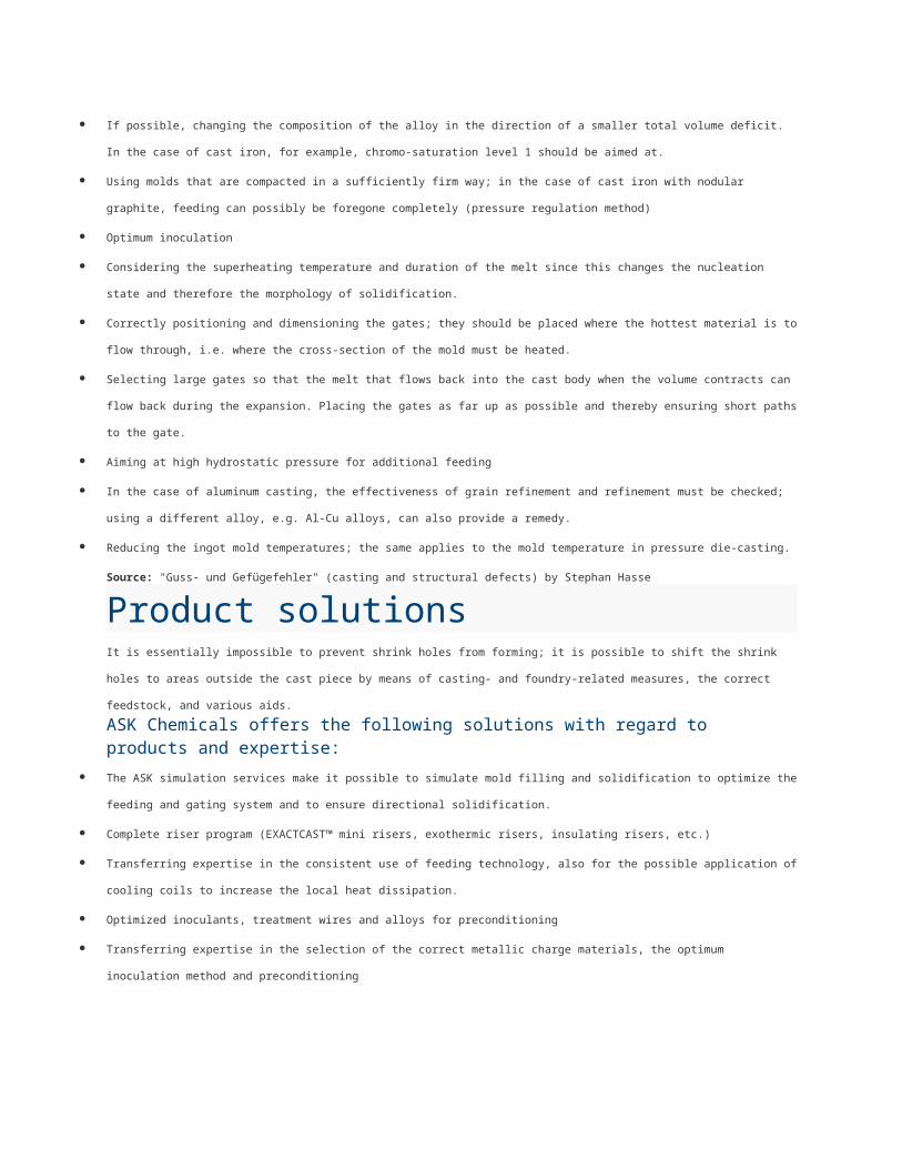
Pinholes: Defect Pattern & CausesPinholes, often also referred to as surface blowholes, occur sporadically and over large areas and can affect all cast piece areas. In many
cases, they only become visible after mechanical processing, but they are always visible to the naked eye. They are primarily found on the
outside of the cast piece or just below the surface of cast pieces made of cast iron with lamellar graphite, nodular graphite and vermicular
graphite and in malleable iron casting and steel casting.
Manifestations
Pinholes can appear in various forms, from spherical blisters with a bare metal surface or covered with small graphite skins to larger,
irregularly shaped cavities accompanied by slags or occurrences of oxidation (Figures 1 to 5).
Figure 1: Pinholes on a section of a cast piece
that are visible to the naked eye. 2:1 magnification
Figure 2: Metallographic sample of the pinhole
marked in Figure 1 with a magnification of 100:1
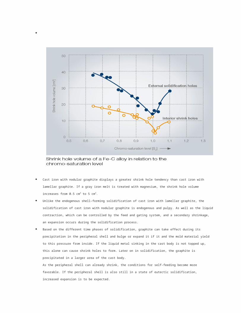
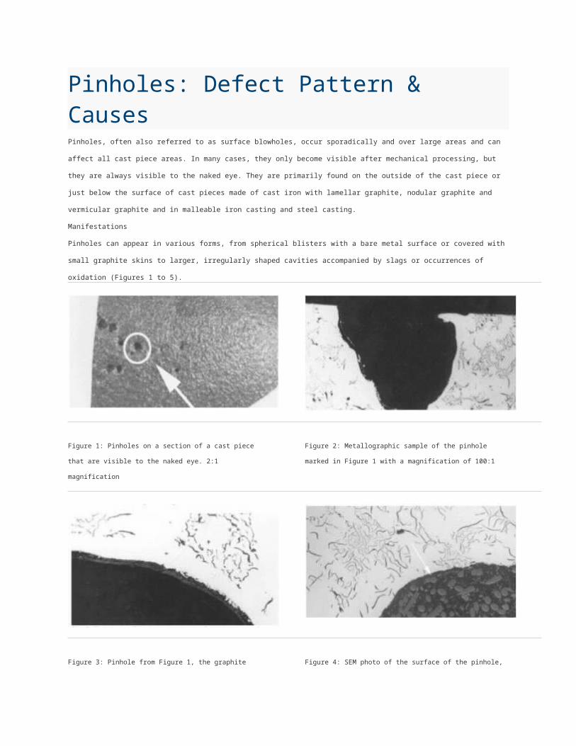
Figure 3: Pinhole from Figure 1, the graphite
film on the wall of the pinhole is clearly visible,
400:1 magnification
Figure 4: SEM photo of the surface of the pinhole,
the point of the EDX measurement is marked
Intensification of pinhole formation in mold-inoculated cast iron with lamellar graphite due to decreasing casting temperature.
Figure 6a: Casting temperature 1400°C Figure 6b: Casting temperature 1350°C,
Sc00, 92; N=90 ppm; 0.01% Ti
(according to W. Bauer)
There are hydrogen pinholes and hydrogen-nitrogen pinholes, which cannot be distinguished from each other, and CO-slag reaction
pinholes. Known possible root causes of this defect include specific properties of the iron on the one hand and specific properties of the mold
material system on the other hand. In a concrete case, the formation of pinholes will often not result from only one cause but rather from the
combined effect of several overlapping causes. Pinholes lead to impairments in coatings such as enameling, hot-dip galvanizing, powder
coating, etc. The ability to withstand static stress is hardly affected by this defect, in particular in the case of ductile cast iron types and a low
stress level. In the case of processed functional surfaces that also have to be leakproof, the defect leads to rejections. In addition, an
unfavorable position of the defect can impair the dynamic strength, so that pinholes cannot be tolerated in safety components that are under
vibratory stress.
Causes
The principle cause of pinholes is based on the specific properties of the metal (i.e. iron), as well as the mold material system.
Hydrogen pinholes and hydrogen-nitrogen pinholes form in three stages
Reaction of the water vapor with the accompanying elements. Metal oxides and atomic hydrogen form, which diffuses into the liquid metal.
Nitrogen-hydrogen compounds are split in a similar way and are also able to diffuse into the liquid metal.
Micro gas bubbles form due to the reaction between the metal oxides and the carbon of the melt.
Hydrogen and possibly nitrogen diffuse into the micro gas bubbles and enlarge the bubbles.
The metallurgic causes of pinhole formation
Excessive hydrogen content in the melt that can occur due to hydrogen carriers such as moist charge materials in general, due to fine-
grained, unprotected ferro-alloys that often adsorb water, highly rusty feedstock (adsorbed OH groups), oils and emulsions that give off
hydrocarbons in particular, and, ultimately, due to the influence of increased air humidity itself.
Excessive nitrogen content in the melt that can be introduced through nitrogen carriers such as scrap steel (up to 130 ppm N, max. 200 ppm
N), rail steel (up to 170 ppm N), pig iron (10 to 60 ppm N) and carburizing compounds (from 0.11 x 10⁴ ppm to 1.675 x 10⁴ ppm N).
The nitrogen content in the cast iron is in the area between 40 and 140 ppm, so that degassing can occur if the formation of bubbles is
induced externally, e.g. though inductive agitation. The critical limit for the formation of pinholes is frequently specified as being between 80
and 100 ppm, although a lower content in combination with CO precipitations can already be critical.
In contrast to steel casting, iron casting is less prone to absorbing gas, since carbon and silicon reduce the solubility and therefore also the
readiness to absorb hydrogen and nitrogen. As a result, a cast iron melt with a low chromo-saturation level is far more sensitive, and this is
also reflected in the frequency of defects in malleable iron casting, which must have a lower chromo-saturation level by nature.
Chromium, molybdenum, manganese, vanadium and titanium increase the solubility of hydrogen and nitrogen, while aluminum,
phosphorous, silicon and carbon reduce it. One case that was examined revealed that cast pieces with the same gas content were
completely sound at 70 ppm Al, while the same cast pieces with 380 ppm Al exhibited a significant formation of pinholes. Higher aluminum
contents can cause the aluminum in the iron to convert to aluminum oxide and hydrogen with the water vapor of the pouring fumes. This
hydrogen then causes the formation of bubbles. This is also where the line should be drawn between gas bubbles with purely metallurgical
causes and the interfacial reaction between the mold/core and the cast piece.
The mold material-related causes of pinhole formation
Too much nitrogen in the molding sand with excessive moisture content
An unfavorable gas atmosphere in the mold cavity, whose causes should be sought in the type and amount of materials that form lustrous
carbon
Too much nitrogen in core sands or too high nitrogen-hydrogen compounds in the core molding material binders
During the pyrolysis of Croning core binders in particular, large amounts of gas are released before a firm peripheral shell has formed.
The mechanism can be explained as follows:
In a reducing atmosphere, ammonia breaks down according to the equation
2NH3 + N2 + 3H2 .
The ammonia is almost fully dissociated at 600°C and under atmospheric pressure. The gas volume doubles in this process, and 1 mole of
nitrogen and 3 moles of hydrogen emerge from 2 moles of ammonia. This hydrogen gas can react with the precipitated carbon monoxide
according to the following equation:
CO + H2 + H2 O + C
The bentonite-bonded mold material is not sufficiently conditioned, which leads to the presence of free water that is not bound in the
bentonite (in the three-layer mineral montmorillonite) and that increases the risk of hydrogen forming.
There are other aspects besides the composition of the iron and the properties of the mold material that influence the formation of pinholes. If
the slag is not skimmed completely, this can lead to slag inclusions that may possibly act as seeds for the formation of gas bubbles. Even if
the slag has been removed, cast iron with nodular graphite contains numerous oxides that can contribute to the formation of pinholes. The
slag that develops during the magnesium treatment also has an impact, even if it is not clear whether it causes a surface defect in a purely
mechanical way or promotes the formation of gas. The casting and gating techniques can also exert influence on the formation of pinholes. A
gating system with a non-turbulent flow and short casting runs reduces the pinhole tendency. Cold drops can also be a cause for pinholes.
They are oxidized and then enveloped by the casting flow. A reaction in which CO forms can occur here and this leads to the formation of
gas bubbles.
Defect preventionPinholes occur sporadically and over large areas and can affect all cast piece areas. In many cases, they only become visible after
mechanical processing, but they are always visible to the naked eye. A number of measures have proven effective in the prevention of
pinholes, and the most important ones are listed below.
An overview of the key measures for preventing pinholes
Reducing hydrogen carriers, i.e. using dry charge materials and avoiding highly rusty, oily feedstock.
Reducing nitrogen carriers (e.g. scrap steel) in the charge make-up; taking the minimum content of titanium (0.02%) into account in the case
of GJL. Using returns that are blasted as far as possible.
Increasing the chromo-saturation level if possible, setting the manganese content to no more than 0.4% Si, reducing the aluminum content
(not ≥ 100 ppm). The negative effect of aluminum is intensified in the presence of titanium, pinholes occur increasingly in the case of a Ti
content of 0.02% and an Al content of 0.01% to 0.2%.
Applying inoculants with reduced aluminum content and ensuring that the casting temperatures are correspondingly high. Low casting
temperatures increase the defect tendency, which is seen as a sign that the formation of pinholes is caused by a surface oxidization of the
melt during casting and solidification.
Changing the gating system so that the melt has little opportunity to oxidize; shortening flow paths, avoiding turbulence
Keeping the hydrogen content of the melt to a minimum by means of intensive boiling during the refining period in steel casting. Ensuring
careful primary deoxidation and short casting times, avoiding long flow paths
Reducing the formation of slag
Reducing the moisture content in the mold material, reducing the amount of inflow of core sand (nitrogen, urea), possibly refreshing the new
sand
Checking and, if necessary, optimizing the content of lustrous carbon of the mold material, possibly changing the material that forms lustrous
carbon.
Possibly reducing the amount of binders in synthetic resin-bonded molds and cores or applying a different binder and/or other catalysts.
Coating molds and cores (nitrogen-adsorbing blocking layers, for example from the ASK Chemicals product range), drying water-based
coatings, checking and optimizing the venting.
Avoiding the input of feeder systems into the mold material system.
Product solutionsIn summary, pinholes are surface pores with a small diameter that are located primarily on the outside of the cast piece or just below the
casting skin. There are hydrogen pinholes, hydrogen-nitrogen pinholes and CO-slag reaction pinholes. The blisters that are not connected to
the surface often contain a thin graphite film.
In essence, it is possible to successfully fight and prevent pinholes with the mold technology and metallurgical measures mentioned above.
ASK Chemicals offers the following solutions with regard to products and expertise:
An optimized cold box binder with high reactivity and a low percentage of solvents
Nitrogen-free no-bake binders
Water- and alcohol-based coatings for highly stressed cold box, hot box or Croning cores in gray iron casting and nodular casting, with
coatings that can be flooded, dipped, sprayed and brushed.
Nitrogen-adsorbing coatings
Materials that form lustrous carbon during casting and that release a large amount of constituents that can be gasified (= volatile
constituents), which in turn contain a sufficient amount of carbon and as little oxygen as possible.
Inoculants with reduced aluminum content
Nitrogen-free feeder systems
Transferring expertise to optimize the gating system in order to give the melt little opportunity for oxidization (short flow paths, avoidance of
turbulence), and to thereby achieve a reduction of slag formation.
Veining: Defect Pattern & CausesVeining is a typical form of defect that occurs in organically bonded mold parts, i.e. a defect that is found
in cores very frequently. It results from the formation of a shell, which forms a vein-like crust. The defect
appears as thin, irregular metallic protuberances.
Core with veining
Veining forms as a result of the silica expanding into the mold cavities, which causes the casting metal to
fill in the resulting gap and form a vein-like crust.
Figure 1: Typical formation of veining
at the inside contour of a cast part.
Composition of the mold material:
100% silica sand, cold box binders
without additives.
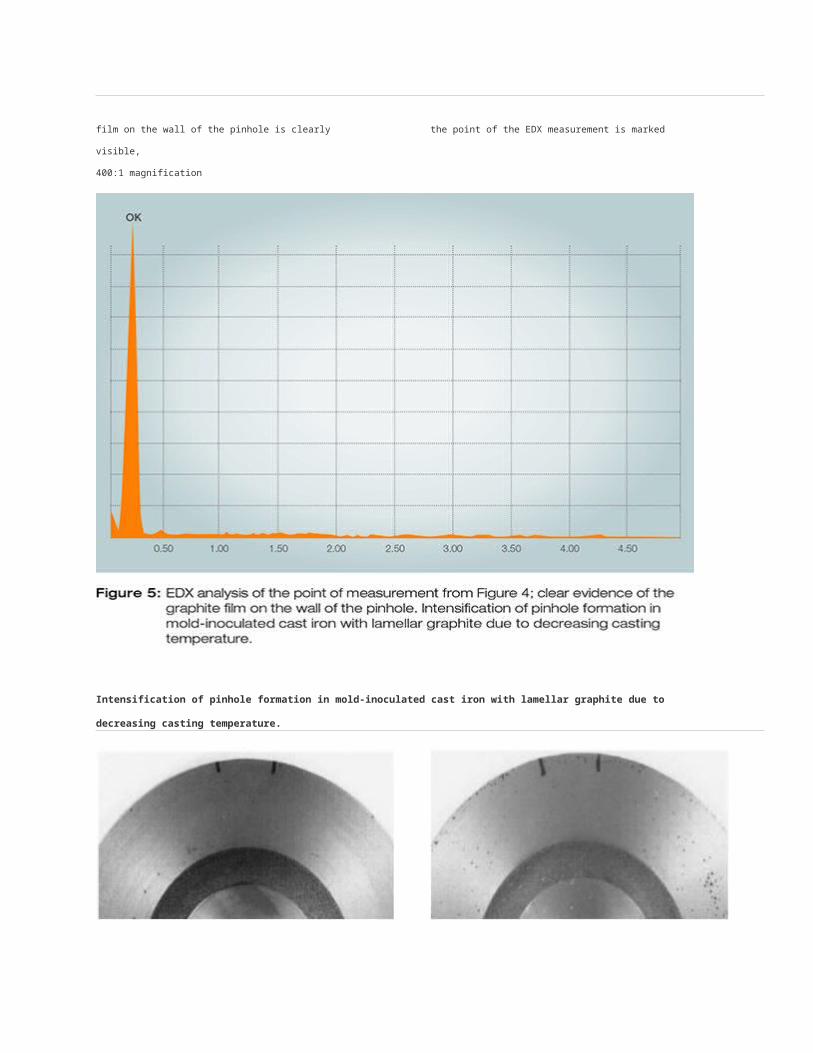
Figure 2: Expected frequency of defects in the various core molding processes
Veining can occur in all foundry materials. Cast iron with nodular graphite, malleable cast iron and bronzes containing lead are particularly
prone to veining, whereas aluminum and magnesium alloys are less prone to veining.
Veining that is caused by cores appears as irregular, fine, thin metallic protuberances in angles or at corners and edges of the cast parts.
Veining leads to an increased level of rework and, in some cases, to rejections.
Veining is likely to occur on the inner contours (cores) of the cast parts when chemically hardened mold materials are used. Its formation is
caused by cracks in the surface of the mold part that can be penetrated by the liquid metal.

Binders and additives are crucial
Since veining must primarily be attributed to the heat-induced expansion of the mold materials, mold parts made of silica sand are
particularly at risk. The liquid metal that surrounds the core causes a temperature gradient between the surface and the center of the core,
which leads to stress.
Up to approx. 400°C, silica sand expands linearly and then displays an abrupt increase in the temperature range of the reversible ß-
conversion (Figure 3), which increases the stress.
Veining is also influenced by the high-temperature behavior of the binder (hot tensile strength, thermoplasticity) and possible additions and
also by the wettability and thermal conductivity of the mold material.
Factors that influence the formation of veining
Grain size and grain particle size distribution (a higher degree of uniformity leads to higher stress, since all silica grains pass through the
conversion temperature simultaneously.)
Intensity of compaction (the higher the intensity of compaction, the higher the packing density, which increases the stress.)
Molding base material (influences the tendency toward defects via the height and uniformity of expansion and the thermal conductivity.)
Casting temperature (high casting temperatures cause a quick silica conversion and thus lead to increased stress in the mold part.)
Defect preventionThe formation of veining is caused by cracks in the surface of the mold part that can be penetrated by the liquid metal. A number of
measures have proven effective in the prevention of veining, and the most important ones are listed below.
An overview of the key measures for preventing veining
Homogeneous distribution of the silica conversion of the entire particle size range by using sand with a low degree of uniformity
Reducing the intensity of compaction
Using a molding base material with higher thermal conductivity, which leads to a smaller stress difference in the grain bond and to faster
solidification
Using mold material additions (mineral or organic additives) from the extensive ASK Chemicals product range of additives
Using suitable coatings
Using suitable binders
Product solutionsVeining is influenced by the high-temperature behavior of the binder, e.g. its thermoplasticity or hot tensile strength. The liquid metal that
surrounds the core causes a temperature gradient between the surface and the center of the core. This involves stress that develops as a
result of structure-related expansion processes of the molding base material (usually silica sand).
ASK Chemicals offers the following solutions with regard to products and expertise:
Performing analyses of the molding sand to determine the degree of uniformity, which should be low
Transferring expertise in the consistent selection of the correct resins for the respective case of application
Using mold material additions, i.e. mineral-based and organically based additives, for the production of cores
Highly effective and highly refractory alcohol- and water-based coatings – depending on the molding base material, the binder and the
material
Transferring expertise in the optimization of the possible molding base materials.


![ENGINE LONG BLOCK - EPM Machine Co. · 2018. 12. 3. · ENGINE LONG BLOCK LITER / CID CYL YEAR VIN DESCRIPTION HEAD CAST # BLOCK CAST # ENGINE PART # CHEVROLET [continued] 2.0 / 122](https://static.fdocuments.in/doc/165x107/610a1ab9736f9c5877433fcb/engine-long-block-epm-machine-co-2018-12-3-engine-long-block-liter-cid.jpg)