ENGINE ALIGNMENT - WinGD
38
ENGINE ALIGNMENT Marine Propulsion Edition 21st June 2021 Prod. Change History B mhu019 A mhu019 wsc003 14.06.2019 EAAD086928 The previous revision (B) of the Alignment Instruction (107.404.952) is re-structured from previous 9 sub-documents to... 4 - - mhu019 bha009 21.10.2013 Rev. Creator Approver Approval Date Change ID Change Synopsis Activity Code E C ENGINE ALIGNMENT PC-Drawing Copyright Winterthur Gas & Diesel Ltd. All rights reserved. By taking possession of the document the recipient recognizes and honours these rights. Neither the whole nor any part of this document may be used in any way for construction, fabrication, marketing or any other purpose nor copied in any way nor made accessible to third parties without the previous written consent of Winterthur Gas & Diesel Ltd. Design Group 9709 Q-Code XXXXX A4 Document ID DAAD040460 PC Page/s 1/37
Transcript of ENGINE ALIGNMENT - WinGD

ENGINE ALIGNMENT
Marine Propulsion Edition 21st June 2021
Pro
d.
Cha
nge
His
tory
B mhu019
A mhu019 wsc003 14.06.2019 EAAD086928 The previous revision (B) of the Alignment Instruction (107.404.952) is re-structured from previous 9 sub-documents to...
4 -
- mhu019 bha009 21.10.2013
Rev. Creator Approver Approval Date Change ID Change Synopsis Activity Code E C
ENGINE ALIGNMENT
PC-Drawing
Copyright Winterthur Gas & Diesel Ltd. All rights reserved. By taking possession of the document the recipient recognizes and honours these rights. Neither the whole nor any part of this document may be used in any way for construction, fabrication, marketing or any other purpose nor copied in any way nor made accessible to third parties without the previous written consent of Winterthur Gas & Diesel Ltd.
Design Group 9709 Q-Code XXXXX
A4 Document ID DAAD040460 PC
Page/s 1/37

Document ID: DAAD040460
Revision: B
Date: 23.06.2021
T_PC-Drawing_Portrait Release: 3.02 (6/22/2021) Page 2 of 37
Table of Contents
1 Introduction and overview .......................................................................................................................................... 6
1.1 Alignment documentation ............................................................................................................................. 6
1.1.1 Instruction ..................................................................................................................................... 6
1.1.1.1 Validity ....................................................................................................................... 6 1.1.1.2 Content ...................................................................................................................... 6
1.1.2 Guidelines ..................................................................................................................................... 6
1.1.2.1 Validity ....................................................................................................................... 6 1.1.2.2 Topics ........................................................................................................................ 6
1.2 WinGD support ............................................................................................................................................... 7
1.2.1 Case-specific alignment support ................................................................................................. 7
1.2.1.1 Scope of WinGD alignment support ......................................................................... 7 Alignment in dock or on slipway ............................................................................... 7 Alignment in partly floating conditions .................................................................... 7
1.2.2 Application ’EnDyn’ for alignment calculation ............................................................................ 7
1.2.3 Creation of ALCs ........................................................................................................................... 7
1.2.4 Spreadsheets for recording and evaluation of measurement results ...................................... 7
1.2.5 Evaluation of alignment measurement results........................................................................... 7
1.3 Alignment during new ship build ................................................................................................................... 8
1.3.1 Project and design stage.............................................................................................................. 8
1.3.1.1 Checking for sufficient shaft bearing distances...................................................... 8 1.3.1.2 Alignment layout calculation (ALC) .......................................................................... 8 1.3.1.3 Complying with permissible epoxy resin chock heights .......................................... 8
1.3.2 Alignment during installation ....................................................................................................... 8
1.3.2.1 Principle ..................................................................................................................... 8 Alignment of propulsion shafts to the stern tube ................................................... 8 Alignment of main engine to the propulsion shafts and to the foundation ........... 8
1.3.2.2 Basic alignment process .......................................................................................... 8 1.3.2.3 Alignment of un-coupled shafts ............................................................................... 9
Principle ..................................................................................................................... 9 Alignment of un-coupled propeller shaft (before floating) ...................................... 9 Alignment of un-coupled intermediate shaft(s) (floating condition) ...................... 9
1.3.2.4 Alignment of un-coupled main engine (floating condition) ..................................... 9 1.3.2.5 Recommended bedplate bending ........................................................................... 9
1.3.3 Alignment measurements ......................................................................................................... 10
1.3.3.1 Alignment measurements types ............................................................................ 10 Gap and sag of un-coupled shafts ......................................................................... 10 Crank web deflections ............................................................................................ 10 Static bearing loads (jack-up tests) ....................................................................... 10
1.3.3.2 Alignment checks during installation ..................................................................... 10 1.4 Alignment checks in normal ship service (after ship delivery) ................................................................. 10
2 Crankshaft models .................................................................................................................................................... 12
2.1 EnDyn program integrated 3D FE based crankshaft models ................................................................... 12
2.1.1 Varying crank angle-dependent stiffness ................................................................................. 12
2.1.2 Consideration of the flywheel, a front disc or a TV damper and/or a free end PTO drive ..... 12
2.2 Equivalent two-dimensional crankshaft model ......................................................................................... 13
2.2.1 Application ................................................................................................................................. 13
2.2.1.1 Restrictions ............................................................................................................. 13 2.2.2 Construction............................................................................................................................... 13
Document ID: DAAD040460
Revision: B
Date: 23.06.2021
T_PC-Drawing_Portrait Release: 3.02 (6/22/2021) Page 3 of 37
2.2.3 Data table .................................................................................................................................. 14
2.2.4 Consideration of the flywheel ................................................................................................... 14
2.2.5 Consideration of a front disc or a TV damper and/or a free end PTO drive ........................... 14
2.2.6 Bending moment at engine integrated thrust bearing ............................................................ 14
3 Static main bearing loads ......................................................................................................................................... 15
3.1 Introduction ................................................................................................................................................. 15
3.1.1 Static loads of stern tube and intermediate bearings ............................................................. 15
3.1.2 Static load distribution at the three aftmost main bearings ................................................... 15
3.1.3 Static loads at the two foremost main bearings ...................................................................... 15
3.1.4 Static loads at the inner main bearings ................................................................................... 15
3.2 Influence of elastic ship hull bending ........................................................................................................ 16
3.3 Measurement of static bearing loads ........................................................................................................ 16
3.3.1 Required set of measurements ................................................................................................ 16
3.3.1.1 Jack-up tests for other main bearings ................................................................... 16 3.3.2 General measurement conditions ............................................................................................ 16
3.3.2.1 Switching off all heat supplies to the machinery foundation ............................... 17 3.3.2.2 Abortion of measurements ..................................................................................... 17
3.4 Recording of bearing load measurement results ...................................................................................... 17
3.5 Evaluation of bearing load measurement results ..................................................................................... 17
3.5.1 Jack correction factors .............................................................................................................. 17
3.5.1.1 Variation of jack correction factors ........................................................................ 18 3.5.2 Tolerances ................................................................................................................................. 18
3.5.2.1 Forward stern tube and intermediate bearings .................................................... 18 3.5.2.2 Engine main bearings ............................................................................................. 18
3.6 Recommended static loads for alignment layout calculations of new ship builds ................................. 19
3.6.1 Referred conditions ................................................................................................................... 19
3.6.2 Validity ........................................................................................................................................ 19
3.6.3 Recommended static load ranges for aftmost mb #1 ............................................................ 19
3.6.3.1 Lower part of recommended range ....................................................................... 19 3.6.3.2 Upper part of recommended range ....................................................................... 19 3.6.3.3 Designs with no forward stern tube bearing ......................................................... 20
3.6.4 Data table .................................................................................................................................. 20
3.7 Recommended static loads before chocking in new ship builds ............................................................. 21
3.7.1 Referred conditions ................................................................................................................... 21
3.7.2 Validity ........................................................................................................................................ 21
3.7.3 Judgement of measured static loads ....................................................................................... 21
3.7.4 Recommended static load ranges for aftmost mb #1 ............................................................ 21
3.7.5 Data table .................................................................................................................................. 22
3.8 Required static loads at ship commissioning / delivery ........................................................................... 23
3.8.1 Referred conditions ................................................................................................................... 23
3.8.2 Validity ........................................................................................................................................ 23
3.8.3 Designs with no forward stern tube bearing ............................................................................ 23
3.8.4 Data table .................................................................................................................................. 24
3.9 Minimum limits for static loads for normal ship service ........................................................................... 25

Document ID: DAAD040460
Revision: B
Date: 23.06.2021
T_PC-Drawing_Portrait Release: 3.02 (6/22/2021) Page 4 of 37
3.9.1 Referred conditions ................................................................................................................... 25
3.9.2 Validity ........................................................................................................................................ 25
3.9.3 Designs with no forward stern tube bearing ............................................................................ 25
3.9.4 Data table .................................................................................................................................. 26
4 Crank web deflections .............................................................................................................................................. 27
4.1 Introduction ................................................................................................................................................. 27
4.2 Crank web deflection measurements ........................................................................................................ 27
4.2.1 Tools ........................................................................................................................................... 27
4.2.2 Turning direction for measurement .......................................................................................... 27
4.2.3 Measurement positions ............................................................................................................ 28
4.2.4 Measurement accuracy............................................................................................................. 28
4.3 Recording and evaluation of crank web deflection measurement results .............................................. 29
4.4 Crank web deflection limits on test bed .................................................................................................... 30
4.4.1 Referred conditions ................................................................................................................... 30
4.4.2 Validity ........................................................................................................................................ 30
4.4.3 Data table .................................................................................................................................. 31
4.5 Crank web deflection limits before chocking in new ship builds ............................................................. 32
4.5.1 Referred conditions ................................................................................................................... 32
4.5.2 Validity ........................................................................................................................................ 32
4.5.3 Threshold value for deviation of vertical web deflections between neighbouring cranks .... 32
4.5.3.1 Threshold value exceeded at the two aftmost cranks .......................................... 32 4.5.3.2 Threshold value exceeded at the two foremost cranks ........................................ 32 4.5.3.3 Threshold value exceeded at inner cranks ........................................................... 33
4.5.4 Data table .................................................................................................................................. 33
4.6 Crank web deflection limits at ship commissioning / delivery ................................................................. 34
4.6.1 Referred conditions ................................................................................................................... 34
4.6.2 Validity ........................................................................................................................................ 34
4.6.3 Threshold value for deviation of vertical web deflections between neighbouring cranks .... 34
4.6.4 Data table .................................................................................................................................. 35
4.7 Crank web deflection limits for normal ship service ................................................................................. 36
4.7.1 Referred conditions ................................................................................................................... 36
4.7.2 Validity ........................................................................................................................................ 36
4.7.3 Data table .................................................................................................................................. 37

Document ID: DAAD040460
Revision: B
Date: 23.06.2021
T_PC-Drawing_Portrait Release: 3.02 (6/22/2021) Page 5 of 37
List of Figures
Figure 2-1: Three-dimensional crankshaft including all running gears plus flywheel attached ................................12
Figure 2-2: Equivalent two-dimensional crankshaft model .........................................................................................13
Figure 4-1: Recommended turning direction during crank web deflection measurement ........................................27
Figure 4-2: Reading positions for crank web deflection measurements ....................................................................28
List of Tables
Table 2-1: Equivalent two-dimensional crankshaft model data .................................................................................14
Table 3-1: Influence of ship draught on engine alignment .........................................................................................16
Table 3-2: Average jack correction factors for engine main bearings .......................................................................18
Table 3-3: Recommended static loads for alignment layout calculations of new ship builds .....................................20
Table 3-4: Recommended static loads before chocking in new ship builds .............................................................22
Table 3-5 Required static loads at ship commissioning / delivery ...........................................................................24
Table 3-6: Minimum limits for static loads for normal ship service .............................................................................26
Table 4-1 Maximum permissible difference between first and last deflection reading value of a crank web .......29
Table 4-2: Crank web deflection limits on test bed .....................................................................................................31
Table 4-3: Crank web deflection limits before chocking in new ship builds ..............................................................33
Table 4-4: Crank web deflection limits at ship commissioning / delivery .................................................................35
Table 4-5: Crank web deflection limits for normal ship service .................................................................................37
List of Abbreviations
3D: three-dimensional
ALC: alignment layout calculation
CPP: controllable pitch propeller
DG: design group: WinGD structure of engine drawing set
EnDyn: WinGD’s program for calculating alignment
FE: finite elements
FPP: fixed pitch propeller
free end PTO: generator driven by the forward end of crankshaft via a speed-up gear
fwd: forward (ahead or bow side of vessel)
mb: engine main bearing
TDC: top dead centre, turning position of a crank with its pin in vertical upward position
TVC: torsional vibration calculation
TV damper: torsional vibration damper
VLCC: very large crude carrier
VLOC: very large ore carrier

Document ID: DAAD040460
Revision: B
Date: 23.06.2021
T_PC-Drawing_Portrait Release: 3.02 (6/22/2021) Page 6 of 37
1 Introduction and overview
The installation and alignment of the propulsion shafts and main engine are the responsibility of the
shipyard. It shall ensure the following for all ship operating conditions:
1. static bearing loads within the limits
2. angular alignment of the propeller shaft inside the aft stern tube bearing bore within the limits
3. crank web deflections within the limits
To fulfil the above mentioned requirements, the factors having an influence on alignment need to be
considered adequately, like for instance operating forces and temperatures as well as elastic ship hull
bending.
The alignment of the propulsion shafts and main engine is carried out according to a case-specific
alignment layout calculation (ALC), and compliance with this is verified by measurements.
1.1 Alignment documentation
The WinGD alignment documentation contains:
1. instructions, providing limits and requirements to comply with
2. recommendations and guidelines, given for reference, to support
in achieving compliance with the requirements and limits
1.1.1 Instruction
1.1.1.1 Validity
This instruction, DG 9709 ’Engine alignment’, applies to the installation of WinGD low-speed engines
in direct-coupled marine propulsion plants.
1.1.1.2 Content
This instruction contains the following information and data:
1. introduction and overview1
2. crankshaft models2
3. static main bearing loads3
4. crank web deflections4
1.1.2 Guidelines
1.1.2.1 Validity
The guidelines and recommendations are given for reference to guide the persons responsible for
design, manufacturing and installation of the marine propulsion plant(s).
The guidelines apply to standard designs of direct-coupled marine propulsion plants, comprising:
• two stern tube bearings
• one or more intermediate bearing(s)
• a fixed pitch propeller (FPP) or a controllable pitch propeller (CPP)
Other designs are supported according to section 1.2.
1.1.2.2 Topics
The following guidelines are issued in addition to this instruction and are provided on the WinGD
corporate webpage under the following links:
1. DAAD040462 ’Guidelines for Layout Calculation’
2. DAAD040464 ’Guidelines for Alignment Process’
3. DAAD040468 ’Guidelines for Measurements’
1 Successor of DAAD040460- ‘Introduction’, DAAD040461- ‘Alignment in brief’ and
DAAD040465- ‘Measurements during normal ship service’. 2 Successor of DAAD040463- ‘Equivalent two-dimensional crankshaft model’. 3 Successor of DAAD040467- ‘Main bearing loads – recommendations and limits’. 4 Successor of DAAD040466- ‘Crank web deflections - limits’.
Document ID: DAAD040460
Revision: B
Date: 23.06.2021
T_PC-Drawing_Portrait Release: 3.02 (6/22/2021) Page 7 of 37
1.2 WinGD support
1.2.1 Case-specific alignment support
WinGD provides case-specific alignment support. This includes for instance:
1. checking the arrangement of shaft bearings according to section 1.3.1.1
2. assistance in creation of ALCs including recommendations for appropriate
case-specific static load distribution of main bearings
3. review of alignment layout calculations
4. support during installation, including evaluation of measurements according to section 1.2.5
In case of new ship builds propelled by WinGD engines, this service is free for the shipyard and our licensee.
1.2.1.1 Scope of WinGD alignment support
WinGD provides support for alignment if the ship building follows usual procedures and also if the
alignment of the shafts and the main engine is performed according to the usual procedures (see
section 1.3.2), in continuous and completely floating state.
Otherwise, detailed information and data about the influence on alignment will be required.
Alignment in dock or on slipway
Carrying out the complete alignment processes already in the dock or on the slipway lies within the
responsibility of the shipyard. WinGD has no objection to this.
Alignment measurements are evaluated on request. However, for the confirmation of the engine
alignment, WinGD requires the exact offset change values for each bearing.
Alternatively, WinGD can evaluate and confirm engine alignment based on measurements taken once
the vessel is floating.
Alignment in partly floating conditions
If the ship hull touches the ground continuously or occasionally (e.g. if the ship floating condition
depends on the tide), then the ship hull bending differs to an unknown degree compared to the
required fully floating condition. For such conditions, WinGD cannot provide support for alignment.
1.2.2 Application ’EnDyn’ for alignment calculation
The EnDyn application for alignment calculations of engines is provided free for our licensees. It can
be ordered by sending an e-mail to the following e-mail address:
1.2.3 Creation of ALCs
WinGD offers complete ALC (packages) as a billable service.
A questionnaire to supply inputs for shaft calculations (TVC, ALC, etc.) is provided on the WinGD
corporate webpage under the following link:
questionnaire for shaft calculations
1.2.4 Spreadsheets for recording and evaluation of measurement results
A spreadsheet in Microsoft Excel file format for recording and evaluation of crank web deflections as
well as jack-up test results for shaft and engine main bearings is provided on the WinGD corporate
webpage under the following link:
engine alignment record sheets
1.2.5 Evaluation of alignment measurement results
WinGD evaluates measurement results for crank web deflections and static bearing loads.
Depending on the result, WinGD will
• either issue a confirmation for the engine alignment
• or give detailed recommendations for re-adjustments
In case of new ship builds propelled by WinGD engines, this service is free for the shipyard and our
licensee.

Document ID: DAAD040460
Revision: B
Date: 23.06.2021
T_PC-Drawing_Portrait Release: 3.02 (6/22/2021) Page 8 of 37
1.3 Alignment during new ship build
This section gives an overview of shaft and engine alignment for a new ship build project.
Detailed information can be found in the mentioned guidelines.
1.3.1 Project and design stage
Detailed information on this subject is given in DAAD040462 ’Guidelines for Layout Calculation‘.
1.3.1.1 Checking for sufficient shaft bearing distances
It is strongly recommended that the shaft bearings are arranged with the required sufficient distances.
It eases alignment during installation and results in safe static loads at low variations.
Recommendations are given in the above mentioned guideline.
Additional support is given according to section 1.2.
1.3.1.2 Alignment layout calculation (ALC)
A design-specific ALC must be done in good time before production of the propulsion shaft line
components begins.
The ALC determines mainly:
1. the static loads and the offsets of the bearings
2. the required slope machining of the aft stern tube bearing bore, which is required to meet the
very stringent limitations of the maximum allowable angular misalignment to the propeller shaft
3. the alignment data for the shafts and the main engine during their installation
1.3.1.3 Complying with permissible epoxy resin chock heights
The WinGD design of engine fixation parts (foundation bolts, thrust sleeves, side stoppers) covers a
certain range of the permissible heights of the main engine's epoxy resin chocks, see DG 9710
’Engine seating / foundation’.
To achieve epoxy resin chock heights within this permissible range, it is necessary to carefully
determine the height and the inclination of the stern tube in relation to the engine foundation, under
consideration of:
1. the bearing offsets obtained by the ALC5
2. the elastic ship hull bending6
3. the height of engine main bearings7
4. the engine-specific design height of epoxy resin chocks
1.3.2 Alignment during installation
Detailed information on this subject is given in DAAD040464 ’Guidelines for Alignment Process’.
1.3.2.1 Principle
Alignment of propulsion shafts to the stern tube
The propulsion shafts and the main engine are aligned in relation to the stern tube and its bearing(s):
• the adjustment of the vertical offsets according to the ALC results in a curved bending line of the
shafts in the vertical plane (side view)
• in the horizontal plane (top view), the shafts and the main engine must be aligned to a straight
line – except if defined differently by the ALC
Alignment of main engine to the propulsion shafts and to the foundation
The crankshaft is aligned to the forward end of the propulsion shafts.
The bedplate is aligned to the ship hull’s integrated foundation top plate.
1.3.2.2 Basic alignment process
Before floating of the vessel, the propeller shaft including propeller and the stern seal(s) are installed.
5 The ALC determines the offsets of stern tube and engine main bearings for afloat condition. 6 Elastic ship hull bending varies the bearing offsets from dry-dock / slipway to afloat condition. 7 Given in column ‘hmb’ of Table 2-1 ‘Equivalent two-dimensional crankshaft model data’, on page 14.

Document ID: DAAD040460
Revision: B
Date: 23.06.2021
T_PC-Drawing_Portrait Release: 3.02 (6/22/2021) Page 9 of 37
After floating of the vessel, alignment is continued as follows:
1. the proper alignment of the propeller shaft to the stern tube bearing(s) is ensured
2. the un-coupled intermediate shaft(s) and the main engine are aligned to the propeller shaft
3. alignment in fully coupled condition of all shafts and the main engine is checked
If alignment complies with the ALC, then the main engine and the intermediate bearings are chocked
and fixed to their foundation.
Otherwise, corrective measures are applied and the checks are repeated.
1.3.2.3 Alignment of un-coupled shafts
This method was developed to enable the adjustment of offsets of the intermediate bearing(s) and the
main engine in relation to the stern tube bearing(s) in floating condition, i.e. with propeller shaft and
propeller already installed.
Principle
For aligning an un-coupled shaft (or a pre-coupled shaft section), the latter is positioned on only two
supports, each in the shape of either an intermediate bearing or a temporary support.
The longitudinal positions of the supports comply with the ALC.
Then these two supports are adjusted until the aft flange of the shaft (or the pre-coupled shaft section)
to be aligned has the following position to the counter flange of the previously aligned aft shaft:
• equal horizontal gap and equal horizontal sag values on both sides
• vertical gap and vertical sag values according to the ALC
Alignment of un-coupled propeller shaft (before floating)
The propeller shaft including the propeller, its nut and its cap as well as the stern tube seals are installed.
If indicated by the ALC, accordingly (position and force) a jack-down force must be applied at the
forward part of the shaft, to exclude a bottom clearance in the forward stern tube bearing.
The propeller shaft alignment to the stern tube bearings is measured, to provide a reference for
rechecking after floating.
Alignment of un-coupled intermediate shaft(s) (floating condition)
The installation and alignment of shafts is carried out progressively from aft to forward:
1. Firstly, the alignment of the propeller shaft to the stern tube is ensured by referring to the above
mentioned reference measurements made before floating.
2. Subsequently, the intermediate shaft is aligned to the propeller shaft.
In case of several intermediate shafts:
a. the aftmost intermediate shaft is aligned to the propeller shaft first
b. then the second-aftmost intermediate shaft will be aligned to the aftmost one
c. this is continued progressively for each additional intermediate shaft until also the foremost
intermediate shaft is aligned to the second-foremost one
3. Finally, the main engine is aligned to the (foremost) intermediate shaft.
1.3.2.4 Alignment of un-coupled main engine (floating condition)
The main engine must be aligned according to two aspects:
1. The crankshaft is aligned to the forward end of the propulsion shafts according to the ALC
2. The main engine bedplate is aligned to the foundation:
a. straight in the horizontal plane and
b. straight or smoothly bent according to section 1.3.2.5 in the vertical plane
Adjustment of height and inclination of the main engine is done by means of the full number of alignment
wedges (or jack screws), according to the engine-specific drawings of DG 9710-01 - ’Tool engine alignment’.
1.3.2.5 Recommended bedplate bending
A straight bedplate is recommended for WinGD engine installation with most ship designs.

Document ID: DAAD040460
Revision: B
Date: 23.06.2021
T_PC-Drawing_Portrait Release: 3.02 (6/22/2021) Page 10 of 37
A smooth bending bedplate is recommended for the following cases:
1. for 5 and 6 cylinder engines with heavy flywheel and heavy front disc (tuning wheel) or TV damper
at the crankshaft forward end, a bedplate hogging (mid bent up) of up to approximately 0.3 mm
is recommended
2. for container vessels of approximately 4500 teu size or larger, a pre-sagging (mid bent down) of
engine bedplate during installation is recommended
1.3.3 Alignment measurements
Detailed information on this subject is given in DAAD040468 ’Guidelines for Measurements’.
1.3.3.1 Alignment measurements types
The following types of measurements are common to check the alignment of direct-coupled
propulsion shaft lines:
Gap and sag of un-coupled shafts
These measurements are applied for checking the alignment of a shaft to the next rear shaft before
they are coupled together. The measurements are carried out on the two opposing opened flanges of
both shafts:
• the gap (angular offset) between the two flanges is measured to check the inclination of the shaft
to be aligned to the next rear shaft
• the sag (radial offset) of the two flanges is measured to check the radial misalignment of the
shaft to be aligned to the next rear shaft
Crank web deflections
This measurement is used to check the alignment of the crankshaft.
The change in distance between the end faces of both main bearing journals of each crank within
nearly one revolution is measured by means of a dial gauge.
Static bearing loads (jack-up tests)
This is the usual method applied for determining the static loads of sleeve bearings.
A hydraulic jack to lift the shaft is arranged next to the bearing; a dial gauge is installed for measurement.
The change of jacking force and the resulting change in vertical shaft offset are recorded during lifting
and lowering of the shaft and plotted as a lifting and a lowering curve.
The evaluation of these two curves delivers the mean jacking force.
The static bearing load is calculated from the product of the mean jacking force and the jack
correction factor, see section 3.5.1.
1.3.3.2 Alignment checks during installation
Alignment in fully coupled condition of all shafts and the main engine is checked by measuring static
bearing loads and crank web deflections upon reaching the following ship building progress:
1. before chocking of the main engine (required)
2. after chocking and fixation of the main engine (optional)8
3. at ship commissioning / delivery (optional, during or after sea trial)
1.4 Alignment checks in normal ship service (after ship delivery)9
In normal ship service, regular recordings of the crank web deflection are required in accordance with
the Maintenance Manual (MM).
The measurements made at ship commissioning / delivery as well as the regular recording of crank
web deflections in normal ship service serve as reference for each additional measurement.
8 Carrying out these optional measurements before chocking of the intermediate bearing(s) provides the possibility of small
corrections before they are also chocked and fixed. 9 The contents of this section and of the engine-specific Maintenance Manual (MM) replace the previous document
DAAD040465 ‘Measurements during normal ship service’.

Document ID: DAAD040460
Revision: B
Date: 23.06.2021
T_PC-Drawing_Portrait Release: 3.02 (6/22/2021) Page 11 of 37
In cases of irregularities or damage or repair, enhanced alignment measurements might be needed,
of which the type and scope depend on the incident, observation and risk.
To ensure the efficiency of such enhanced alignment measurements, it is recommended that they are
clarified in advance and in detail with WinGD, independent of the company performing them on site.
Document ID: DAAD040460
Revision: B
Date: 23.06.2021
T_PC-Drawing_Portrait Release: 3.02 (6/22/2021) Page 12 of 37
2 Crankshaft models
2.1 EnDyn program integrated 3D FE based crankshaft models
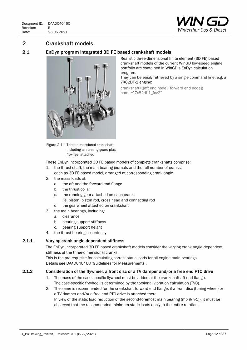
Figure 2-1: Three-dimensional crankshaft
including all running gears plus
flywheel attached
Realistic three-dimensional finite element (3D FE) based
crankshaft models of the current WinGD low-speed engine
portfolio are contained in WinGD’s EnDyn calculation
program.
They can be easily retrieved by a single command line, e.g. a
7X82DF-1 engine:
crankshaft=([aft end node],[forward end node])
name=”7x82df-1_fcv2”
These EnDyn incorporated 3D FE based models of complete crankshafts comprise:
1. the thrust shaft, the main bearing journals and the full number of cranks,
each as 3D FE based model, arranged at corresponding crank angle
2. the mass loads of:
a. the aft and the forward end flange
b. the thrust collar
c. the running gear attached on each crank,
i.e. piston, piston rod, cross head and connecting rod
d. the gearwheel attached on crankshaft
3. the main bearings, including:
a. clearance
b. bearing support stiffness
c. bearing support height
4. the thrust bearing eccentricity
2.1.1 Varying crank angle-dependent stiffness
The EnDyn incorporated 3D FE based crankshaft models consider the varying crank angle-dependent
stiffness of the three-dimensional cranks.
This is the pre-requisite for calculating correct static loads for all engine main bearings.
Details see DAAD040468 ’Guidelines for Measurements’.
2.1.2 Consideration of the flywheel, a front disc or a TV damper and/or a free end PTO drive
1. The mass of the case-specific flywheel must be added at the crankshaft aft end flange.
The case-specific flywheel is determined by the torsional vibration calculation (TVC).
2. The same is recommended for the crankshaft forward end flange, if a front disc (tuning wheel) or
a TV damper and/or a free end PTO drive is attached there.
In view of the static load reduction of the second-foremost main bearing (mb #(n-1)), it must be
observed that the recommended minimum static loads apply to the entire rotation.
Document ID: DAAD040460
Revision: B
Date: 23.06.2021
T_PC-Drawing_Portrait Release: 3.02 (6/22/2021) Page 13 of 37
2.2 Equivalent two-dimensional crankshaft model
2.2.1 Application
Equivalent two-dimensional10 crankshaft models are provided for calculating alignment with
applications other than WinGD’s EnDyn.
The WinGD equivalent two-dimensional crankshaft models deliver just the calculated static loads for
the three aftmost engine main bearings (aftmost mb #1, mb #2 and mb #3) only, even if the model is
extended with additional main bearings.
The following deviations occur compared to the results achieved by means of the EnDyn integrated 3D
FE-based models, when the aftmost crank #1 is at top dead centre (TDC):
• about 5% for aftmost mb #1 and mb #2
• about 10% for mb #3, or even more in some special cases
IMPORTANT:
The correct application of all data given in Table 2-1 below for the equivalent two-dimensional
crankshaft model according to Figure 2-2 is the pre-requisite for the applicability of the WinGD
recommended static loads for layout calculations given in Table 3-3 on page 20.
They do not apply to alignment calculations which for instance:
• consider other or even infinite stiffness for the engine main bearings
• contain different equivalent two-dimensional crankshaft model data or even omit some
2.2.1.1 Restrictions
Further results that the calculation might yield for the two-dimensional crankshaft model in addition to
the above mentioned, like static loads for main bearings mb #4 and mb #5, bending stress, etc. are
not realistic and therefore cannot be evaluated.
2.2.2 Construction
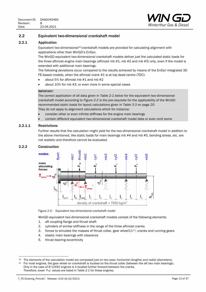
Figure 2-2: Equivalent two-dimensional crankshaft model
WinGD equivalent two-dimensional crankshaft models consist of the following elements:
1. aft coupling flange and thrust shaft
2. cylinders of similar stiffness in the range of the three aftmost cranks
3. forces to simulate the masses of thrust collar, gear wheel1111, cranks and running gears
4. elastic main bearings with clearance
5. thrust bearing eccentricity
10 The elements of the calculation model are composed just on two axes: horizontal (lengths) and radial (diameters). 11 For most engines, the gear wheel on crankshaft is located on the thrust collar (between the aft two main bearings).
Only in the case of 8-12X92 engines is it located further forward between the cranks.
Therefore, lower ‘FTB’ values are listed in Table 2-1 for these engines.
Document ID: DAAD040460
Revision: B
Date: 23.06.2021
T_PC-Drawing_Portrait Release: 3.02 (6/22/2021) Page 14 of 37
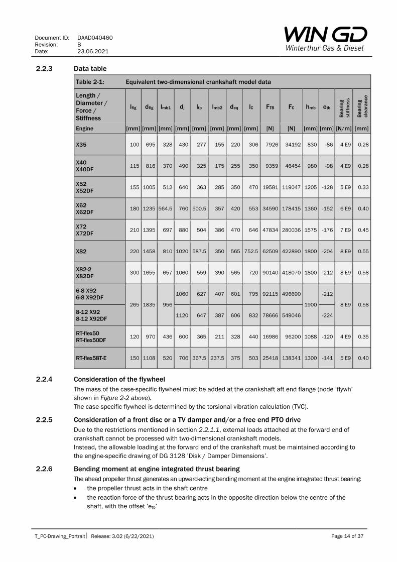
2.2.3 Data table
Table 2-1: Equivalent two-dimensional crankshaft model data
Length /
Diameter /
Force /
Stiffness
lflg dflg lmb1 dj ltb lmb2 deq lC FTB FC hmb etb
B
ea
rin
g
stif
fne
ss
B
ea
rin
g
cle
ara
nce
Engine [mm] [mm] [mm] [mm] [mm] [mm] [mm] [mm] [N] [N] [mm] [mm] [N/m] [mm]
X35 100 695 328 430 277 155 220 306 7926 34192 830 -86 4 E9 0.28
X40
X40DF 115 816 370 490 325 175 255 350 9359 46454 980 -98 4 E9 0.28
X52
X52DF 155 1005 512 640 363 285 350 470 19581 119047 1205 -128 5 E9 0.33
X62
X62DF 180 1235 564.5 760 500.5 357 420 553 34590 178415 1360 -152 6 E9 0.40
X72
X72DF 210 1395 697 880 504 386 470 646 47834 280036 1575 -176 7 E9 0.45
X82 220 1458 810 1020 587.5 350 565 752.5 62509 422890 1800 -204 8 E9 0.55
X82-2
X82DF 300 1655 657 1060 559 390 565 720 90140 418070 1800 -212 8 E9 0.58
6-8 X92
6-8 X92DF
265 1835 956
1060 627 407 601 795 92115 496690
1900
-212
8 E9 0.58
8-12 X92
8-12 X92DF 1120 647 387 606 832 78666 549046 -224
RT-flex50
RT-flex50DF 120 970 436 600 365 211 328 440 16986 96200 1088 -120 4 E9 0.35
RT-flex58T-E 150 1108 520 706 367.5 237.5 375 503 25418 138341 1300 -141 5 E9 0.40
2.2.4 Consideration of the flywheel
The mass of the case-specific flywheel must be added at the crankshaft aft end flange (node ’flywh’
shown in Figure 2-2 above).
The case-specific flywheel is determined by the torsional vibration calculation (TVC).
2.2.5 Consideration of a front disc or a TV damper and/or a free end PTO drive
Due to the restrictions mentioned in section 2.2.1.1, external loads attached at the forward end of
crankshaft cannot be processed with two-dimensional crankshaft models.
Instead, the allowable loading at the forward end of the crankshaft must be maintained according to
the engine-specific drawing of DG 3128 ’Disk / Damper Dimensions’.
2.2.6 Bending moment at engine integrated thrust bearing
The ahead propeller thrust generates an upward-acting bending moment at the engine integrated thrust bearing:
• the propeller thrust acts in the shaft centre
• the reaction force of the thrust bearing acts in the opposite direction below the centre of the
shaft, with the offset ’etb’

Document ID: DAAD040460
Revision: B
Date: 23.06.2021
T_PC-Drawing_Portrait Release: 3.02 (6/22/2021) Page 15 of 37
3 Static main bearing loads
3.1 Introduction
Shaft bearings as well as engine main bearings are of sleeve bearing type. They have clearance and
require a continuous downward-acting static load for reliable operation:
1. for each shaft bearing a static load with sufficient safety against zero load and against exceeding
the maximum load specified by the manufacturer must be ensured
2. for each engine main bearing a static load complying with the minimum limits of normal ship
service given in section 3.9 must be ensured
The WinGD required minimum static load limits must be maintained for each engine main bearing
when the ship is at stopped condition and the propulsion plant is ready for operation.
Meeting this requirement excludes the possibility of an excessive static load for each of the engine
main bearings.
To support in achieving compliance with the minimum limits of static main bearing loads in normal ship
service, WinGD provides recommended static main bearing loads for ALCs and for alignment checks
before chocking as well as required static main bearing loads at commissioning / delivery of new ship
builds. These data are based on WinGD long-term experience in aligning marine propulsion plants.
3.1.1 Static loads of stern tube and intermediate bearings
Due to the external load of the propeller, the aft stern tube bearing is always well loaded.
The static loads of the forward stern tube bearing and the intermediate bearing(s) are much lower and
vary due to the influence of elastic ship hull bending.
Accordingly, these bearings must be carefully adjusted in the ALC, to ensure that the static loads are
within the specifications, with sufficient safety margins against zero load and overload.
3.1.2 Static load distribution at the three aftmost main bearings
A main focus of engine alignment is the static load distribution at the three aftmost main bearings.
It is influenced by the design and by the alignment of the direct-coupled propeller and intermediate
shafts. These shafts follow the elastic ship hull bending which varies according to the ship's draught
and trim.
The above mentioned influences must be considered in the ALC, by pre-compensating for the related
changes in static load distribution at the three aftmost main bearings as explained in section 3.2.
Corresponding recommendations for static main bearing loads are given in section 3.6.
The successful application of the ALC during alignment before chocking is verified by measurements
according to section 3.7.
These measurements are repeated at ship commissioning / delivery, see section 3.8.
In normal ship service, static bearing loads are only measured in special/exceptional cases, see
section 3.9.
3.1.3 Static loads at the two foremost main bearings
If there is an external load attached at the forward end of crankshaft, like a front disc (tuning wheel), a
TV damper and/or a free end PTO drive, then the static loads of the two foremost main bearings need
to be considered as well:
1. during design, this is considered according to sections 2.1.2 item 2 and/or 2.2.5
2. when aligning during installation, the measurement of static loads at the two foremost main
bearings is needed if the threshold value for deviation of vertical web deflections between
neighbouring cranks is exceeded at the two foremost cranks #(n) and #(n-1), see sections
3.3.1.1 and 4.5.3
3.1.4 Static loads at the inner main bearings
The static loads of the inner main bearings mb #4 to mb #(n-2), depend on the bedplate alignment as
well as on the machining of the bedplate, bearing shells and crankshaft.
Measuring of their static loads is also only required if indicated according to sections 3.3.1.1 and 4.5.3.

Document ID: DAAD040460
Revision: B
Date: 23.06.2021
T_PC-Drawing_Portrait Release: 3.02 (6/22/2021) Page 16 of 37
3.2 Influence of elastic ship hull bending
In stopped flat-water conditions, the ship hull bending depends mainly on ship draught and trim and
also on component temperatures.
Regarding the main engine, mainly the three aftmost main bearings and the web deflections of the
two aftmost cranks are affected as shown in Table 3-1.
Table 3-1: Influence of ship draught on engine alignment
Condition machinery
foundation
shape
static main bearing loads crank web
deflection
aftmost crank #1 aftmost mb #1 mb #2
light ballast draught usual for alignment
during new ship build
more sagging
or
less hogging
↘
reduced
↗
increased
design to
maximum draught
less sagging
or
more hogging
↗
increased
↘
reduced
During ship construction, the alignment of the shafts and the main engine is usually carried out in the
empty ship and therefore at light ballast draught.
In this condition, the following static load distribution must be adjusted at the three aftmost engine
main bearings:
• high static loads at mb #2 and mb #3
• low static load at aftmost mb #1
3.3 Measurement of static bearing loads
3.3.1 Required set of measurements
Alignment must be checked during installation by carrying out the following set of measurements after
coupling of all shafts and the main engine:
1. web deflections of all cranks
2. jack-up tests of the forward stern tube bearing and of each intermediate bearing
3. jack-up tests of the three aftmost engine main bearings, i.e. aftmost mb #1, mb #2 and mb #3
3.3.1.1 Jack-up tests for other main bearings
Jack-up tests for other main bearings, i.e. mb #4 to foremost mb #(n), are needed if the threshold value
for deviation of vertical web deflections between neighbouring cranks is exceeded, see section 4.5.3.
3.3.2 General measurement conditions
The following conditions apply to all alignment measurements (crank web deflections as well as static
bearing loads) in the ship:
1. the ship is floating continuously, no interim change of draught or trim
2. the main engine is completely assembled, with all pistons and running gears installed as well as
all tie rods fully tightened12
3. the propeller, the intermediate shaft(s) and the main engine are coupled, supported only by their
bearings – any tools or devices for mounting or installing the shafts, such as temporary
support(s), jack-down force(s), etc. must be removed
4. all heat sources in the machinery foundation are switched off in good time before starting each
set of measurements according to section 3.3.2.1
5. no intermediate changes in the alignment may occur before completion of all measurements of a
condition, otherwise the measurements must be aborted and started anew according to section
3.3.2.2
6. the ship and the propulsion plant are in a stopped condition
12 According to the engine-specific drawing of DG 0351 – ‘Assembly instructions’

Document ID: DAAD040460
Revision: B
Date: 23.06.2021
T_PC-Drawing_Portrait Release: 3.02 (6/22/2021) Page 17 of 37
Further conditions apply in addition to the above mentioned. They are listed for each of the
measurement conditions described below.
3.3.2.1 Switching off all heat supplies to the machinery foundation
Any heat supply to the machinery foundation can falsify alignment measurement results, particularly:
1. the heating of the lubricating oil drain tank below the main engine
2. the pre-heater of the main engine lubricating oil separator
3. any other heat source in the double bottom of the engine room
Each of these heat sources must be switched off in good time before starting measurements and they
must remain switched-off until all measurements are completed:
• at least 8 hours before measurements at cold conditions (crankcase temperature less than 30°C)
• at least 4 hours before measurements at warm conditions (crankcase temperature above 30°C)
• at least 2 hours before measurements at hot conditions (crankcase temperature above 40°C)
In contrast, the remaining heat of the main engine body from previous operation, in the lubricating oil
drain tank as well as other tanks in the engine room double bottom, is not problematic.
The main engine crankcase temperature must always be added to the measurement records.
3.3.2.2 Abortion of measurements
If alignment settings are changed before all measurements of a condition are completed, then the
measurements must be aborted immediately.
Subsequently, a waiting time of 6 hours at least are required for the change(s) to become fully effective.
Thereafter, the complete set of measurements of the referred condition must be repeated.
3.4 Recording of bearing load measurement results
Careful recording of bearing load measurement results is essential.
Information about the measurement conditions and the measurement tools must also be included in
the records for a clear understanding and a correct judgement of the alignment measurement results.
WinGD provides spreadsheets for recording and evaluation of measurement results – see section 1.2.4.
3.5 Evaluation of bearing load measurement results
Details about the evaluation of jack-up test measurement results are given in DAAD040468
’Guidelines for Measurements’.
WinGD provides support according to section 1.2.5.
3.5.1 Jack correction factors
There are several sources for jack correction factors:
1. a measurement-specific reverse calculation13
2. the referred ALC
3. if the referred ALC does not contain jack correction factors for the engine main bearings, then the
average jack correction factors given in Table 3-2 below can be applied
13 Applied by WinGD for evaluation of bearing load measurements.

Document ID: DAAD040460
Revision: B
Date: 23.06.2021
T_PC-Drawing_Portrait Release: 3.02 (6/22/2021) Page 18 of 37
Table 3-2: Average jack correction factors for engine main bearings
Bearing Jack position Dial gauge position Jack
correction
factor
aftmost mb #1 below flywheel
either on top of flywheel
or on top of crankshaft next to the flywheel
or on coupling flange next to flywheel
1.6
mb #2 (forward side)
below the aft web
of aftmost crank #1
on top of the aft web
of aftmost crank #1 1
mb #3 (aft side)
below the forward web
of aftmost crank #1
on top of the forward web
of aftmost crank #1 1
mb #4 to
foremost mb #(n) below the web
next to relevant mb
on top of the web
next to relevant mb 1
3.5.1.1 Variation of jack correction factors
A jack correction factor depends on:
1. the position of the jack in relation to the bearings
2. the actual static load distribution of bearings
Due to different static load distributions, the jack correction factor for most bearings varies only within
a range of ±0.05.
In contrast, the jack correction factor of mb #2 may change significantly, depending on the actual
static load distribution of mb #1 and mb #2:
• from approximately 0.8 in cases of a low loaded aftmost mb #1 and a high loaded mb #2
• to approximately 1.3 in cases of a high loaded aftmost mb #1 and a low loaded mb #2
3.5.2 Tolerances
3.5.2.1 Forward stern tube and intermediate bearings
For the measured static loads of the forward stern tube bearing and the intermediate bearing(s),
either the tolerance according to class rules or according to ALC applies – whichever is tighter.
Usual tolerances are ±10 to ±20%.
3.5.2.2 Engine main bearings
The engine main bearings have the highest sensitivity for offset changes, especially the two aftmost
main bearings.
Therefore, the above mentioned tolerance usually applied for the measured static loads of the shaft
bearings cannot be applied for main bearings as well.
However, the static load distribution of the three aftmost main bearings measured during installation
should be similar, like in the ALC.

Document ID: DAAD040460
Revision: B
Date: 23.06.2021
T_PC-Drawing_Portrait Release: 3.02 (6/22/2021) Page 19 of 37
3.6 Recommended static loads for alignment layout calculations of new ship builds
3.6.1 Referred conditions
The recommended static loads for alignment layout calculations of new ship builds, given in Table 3-3
below, refer to the general measurement conditions specified in section 3.3.2 and are additional to
the following conditions:
1. the manufacturing of the ship hull and its superstructure(s), including all main welding works, has
been completed
2. the ship is in a stopped condition and floating continuously, with light ballast to ballast draught
3. the propulsion plant has ambient temperatures, this comprises:
a. a. the main engine
b. b. the intermediate bearing support(s)
c. c. the double bottom with the main engine foundation and its integrated main engine
lubricating oil drain tank
3.6.2 Validity
The recommended static loads for alignment layout calculations of new ship builds apply only to
calculations that consider the following:
1. main bearings with elastic supports and clearance according to section 2
2. distribution of static loads on the three aftmost main bearings according to section 3.2
3. the conditions specified above
The recommended static loads for layout calculations are given for guidance only, but not as limits.
They do not apply to any measurements.
3.6.3 Recommended static load ranges for aftmost mb #1
To enable the consideration of the major factors influencing the advisable static load distribution of
the three aftmost engine main bearings, the recommended static loads for aftmost mb #1 are
provided as ranges.
However, these ranges are neither limit values nor recommended tolerance ranges.
3.6.3.1 Lower part of recommended range
The more the following influences apply, the lower the recommended static bearing load on aftmost
mb # 1:
1. a large difference of approximately 10m or more between the light ballast or ballast draught
during final alignment and the maximum draught in normal ship service,
e.g. very large crude carriers (VLCCs) and very large bulk carriers (VLOCs)
2. a short distance between the foremost intermediate bearing and aftmost mb #1,
i.e. near the WinGD recommended minimum distance for shaft bearings or even lower
3. a light flywheel
If all three of the above mentioned influences apply, then the lowest value of the range is
recommended.
3.6.3.2 Upper part of recommended range
The more the following influences apply, the higher the recommended static bearing load on aftmost
mb # 1:
1. a small difference of just approximately 6m or less between the light ballast or ballast draught
during final alignment and the maximum draught in normal ship service,
e.g. gas tankers, vehicle carriers, RoRo vessels and livestock carriers
2. a large distance between the foremost intermediate bearing and aftmost mb #1,
i.e. near the WinGD recommended maximum distance for shaft bearings or even higher
3. a heavy flywheel
If all three of the above mentioned influences apply, then the highest value of the range is
recommended.

Document ID: DAAD040460
Revision: B
Date: 23.06.2021
T_PC-Drawing_Portrait Release: 3.02 (6/22/2021) Page 20 of 37
3.6.3.3 Designs with no forward stern tube bearing
For designs with no forward stern tube bearing and just one intermediate bearing, an increased static
load for the aftmost mb # 1 as listed in the table’s notes below is strongly recommended.
3.6.4 Data table
Table 3-3: Recommended static loads for alignment layout calculations of new ship builds
cold - stopped condition, light ballast to ballast draught
aftmost mb #1 mb #2 mb #3 mb #4 to
foremost mb #(n)
Engine [kN] [kN] [kN] [kN]
X35 10 – 20*1 25 30 12
X40
X40DF 12 – 25*2 40 40 15
X52
X52DF 15 – 50*3 80 90 25
X62
X62DF 15*4 – 80 130 150 40
X72
X72DF 15*4 – 120 160 200 50
X82 15*5 – 130 290 280 90
X82-2
X82DF 15*5 – 130 290 280 90
X92
X92DF 15*5 – 130 310 300 90
RT-flex50
RT-flex50DF 15 – 45*3 65 75 30
RT-flex58T-E 15 – 65*3 100 110 30
Notes of table:
For designs with no forward stern tube bearing and just one intermediate bearing, increased static
loads are strongly recommended for aftmost mb # 1:
*1: 20 – 30kN
*2: 25 – 35kN
*3: 40 – 70kN
*4: ≥ 60kN
*5: ≥ 80kN

Document ID: DAAD040460
Revision: B
Date: 23.06.2021
T_PC-Drawing_Portrait Release: 3.02 (6/22/2021) Page 21 of 37
3.7 Recommended static loads before chocking in new ship builds
The alignment of the propulsion shafts and the main engine is usually carried out according to the
data of the cold, stopped condition of the case-specific ALC – see also section 1.3.2.
Information on static bearing load measurements, recordings and evaluations is provided in sections
1.3.3, 3.3, 3.4 and 3.5.
3.7.1 Referred conditions
The recommended static loads before chocking in new ship builds, given in Table 3-4 below, refer to
the general measurement conditions specified in section 3.3.2 and additionally to the conditions
specified in section 3.6.1 for ALCs.
Any deviation therefrom must be added to the measurement records.
Furthermore, the following is mandatory:
1. the main engine must be supported by the full number of alignment wedges (or jack screws),
according to the engine-specific drawings of DG 9710-01 –’Tool engine alignment’
2. all heat sources that supply the machinery foundation must be switched off in good time
before starting measurements according to section 3.3.2.1
3.7.2 Validity
The recommended static loads before chocking in new ship builds apply to the conditions specified
above.
The recommended static loads before chocking are given for guidance only, but not as limits.
They do not apply to the following measurements:
1. on test bed
2. after chocking and before ship commissioning / delivery, see section 3.8.2
3. at ship commissioning / delivery
4. in normal ship service
3.7.3 Judgement of measured static loads
Alignment is optimum if the static load distribution of the three aftmost engine main bearings
complies with the ALC, see section 3.5.2.2.
In cases of standard ship designs as described in section 1.1.2.1, the engine alignment is still
acceptable if the recommended static loads before chocking in new ship builds are at least met.
If they are not met, or in the case of non-standard designs, WinGD must be contacted for support.
3.7.4 Recommended static load ranges for aftmost mb #1
For designs with no forward stern tube bearing and just one intermediate bearing, an increased static
load for the aftmost mb # 1 is strongly recommended, as listed in the table’s notes below.

Document ID: DAAD040460
Revision: B
Date: 23.06.2021
T_PC-Drawing_Portrait Release: 3.02 (6/22/2021) Page 22 of 37
3.7.5 Data table
Table 3-4: Recommended static loads before chocking in new ship builds
cold - stopped condition, light ballast to ballast draught
static loads aftmost mb #1 mb #2 mb #3 mb #4 to
foremost mb #(n)
Engine [kN] [kN] [kN] [kN]
X35 10 – 25*1 20 15 10
X40
X40DF 12 – 30*2 30 20 15
X52
X52DF 15 – 55*3 70 40 20
X62
X62DF 15*4 – 85 110 70 30
X72
X72DF 15*4 – 140 120 80 40
X82 15*5 – 150 220 140 40
X82-2
X82DF 15*5 – 150 220 140 40
X92
X92DF 15*5 – 160 220 140 40
RT-flex50
RT-flex50DF 15 – 50*3 55 35 20
RT-flex58T-E 15 – 75*3 85 50 20
Notes of table:
For designs with no forward stern tube bearing and just one intermediate bearing, increased static
loads are strongly recommended for aftmost mb # 1:
*1: 20 – 35kN
*2: 25 – 40kN
*3: 40 – 80kN
*4: ≥ 60kN
*5: ≥ 80kN
Document ID: DAAD040460
Revision: B
Date: 23.06.2021
T_PC-Drawing_Portrait Release: 3.02 (6/22/2021) Page 23 of 37
3.8 Required static loads at ship commissioning / delivery
The required static loads at ship commissioning / delivery apply to measurements made during or
after the sea trial of a new ship build.
Information on static bearing load measurements, recordings and evaluations is provided in sections
1.3.3, 3.3, 3.4 and 3.5.
3.8.1 Referred conditions
The required static loads at ship commissioning / delivery, given in Table 3-5 below, refer to the
general measurement conditions specified in section 3.3.2 and are additional to the following
conditions:
1. the ship is completely built and ready for sea trial / operation
2. the installation of the stern tube and its bearing(s) is completed, the intermediate bearing(s) and
the main engine are chocked and fixed to their foundations
3. the ship is in a stopped condition and floating continuously, with light ballast to ballast draught
4. the propulsion plant is at cold, warm or hot condition
Any deviation therefrom must be added to the measurement records.
3.8.2 Validity
The required static loads at ship commissioning / delivery apply to the conditions specified above.
In addition, they can also be applied to additional measurements made after chocking and before
ship commissioning / delivery.
However, if the ship has not been at sea before, then the tolerance range must not be fully exploited.
In such cases, reserves are needed to avoid the development of inadmissible values due to
subsequent settling effects and the release of welding stress.
The required static loads at ship commissioning / delivery do not apply to the following
measurements:
1. on test bed
2. before chocking
3. at full draught condition, see section 3.9.2
4. in normal ship service
3.8.3 Designs with no forward stern tube bearing
For designs with no forward stern tube bearing and just one intermediate bearing, an increased static
load for the aftmost mb # 1 is strongly recommended, as listed in the table’s notes below.

Document ID: DAAD040460
Revision: B
Date: 23.06.2021
T_PC-Drawing_Portrait Release: 3.02 (6/22/2021) Page 24 of 37
3.8.4 Data table
Table 3-5 Required static loads at ship commissioning / delivery
cold -, warm - or hot - stopped condition, light ballast to ballast draught
aftmost mb #1 mb #2 mb #3 mb #4 to
foremost mb #(n)
Engine [kN] [kN] [kN] [kN]
X35 8*1 15 15 10
X40
X40DF 10*2 25 20 15
X52
X52DF 10*3 55 40 20
X62
X62DF 10*4 100 70 30
X72
X72DF 10*4 100 80 40
X82 10*5 200 100 40
X82-2
X82DF 10*5 200 100 40
X92
X92DF 10*5 220 140 40
RT-flex50
RT-flex50DF 10*3 45 35 20
RT-flex58T-E 10*3 70 50 20
Notes of table:
For designs with no forward stern tube bearing and just one intermediate bearing, increased static
loads are strongly recommended for aftmost mb # 1:
*1: ≥ 16kN
*2: ≥ 20kN
*3: ≥ 30kN
*4: ≥ 40kN
*5: ≥ 60kN

Document ID: DAAD040460
Revision: B
Date: 23.06.2021
T_PC-Drawing_Portrait Release: 3.02 (6/22/2021) Page 25 of 37
3.9 Minimum limits for static loads for normal ship service
After ship delivery, jack-up tests of engine main bearings are only required in special/exceptional
cases as explained in section 1.4.
Information on static bearing load measurements, recordings and evaluations is provided in sections
1.3.3, 3.3, 3.4 and 3.5.
3.9.1 Referred conditions
The minimum limits for static loads for normal ship service, given in Table 3-6 below, refer to the
general measurement conditions specified in section 3.3.2 and are additional to the following
conditions:
1. the ship is in normal service condition, stopped and ready for operation
2. the ship is floating continuously, with any draught and trim within the limits of normal ship
service, i.e. between light ballast draught and maximum draught
3. the propulsion plant is at cold, warm or hot condition
Any deviation therefrom must be added to the measurement records.
3.9.2 Validity
The minimum limits for static loads for normal ship service apply to the conditions specified above.
In addition, they can also be applied to measurements made at full draught condition at ship
commissioning / delivery.
However, if the ship has not been at sea before, then the tolerance range must not be fully exploited.
In such cases, reserves are needed to avoid the development of inadmissible values due to
subsequent settling effects and the release of welding stress.
The minimum limits for static loads for normal ship service do not apply to the following
measurements:
1. on test bed
2. before chocking
3. at ship commissioning / delivery at light ballast or ballast draught condition, see section 3.8.2
3.9.3 Designs with no forward stern tube bearing
For designs with no forward stern tube bearing and just one intermediate bearing, the minimum limit
for static load at the aftmost mb # 1 is double the value given in Table 3-6 below.
Document ID: DAAD040460
Revision: B
Date: 23.06.2021
T_PC-Drawing_Portrait Release: 3.02 (6/22/2021) Page 26 of 37
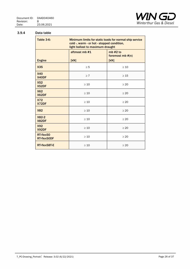
3.9.4 Data table
Table 3-6: Minimum limits for static loads for normal ship service
cold -, warm - or hot - stopped condition,
light ballast to maximum draught
aftmost mb #1 mb #2 to
foremost mb #(n)
Engine [kN] [kN]
X35 5 10
X40
X40DF 7 15
X52
X52DF 10 20
X62
X62DF 10 20
X72
X72DF 10 20
X82 10 20
X82-2
X82DF 10 20
X92
X92DF 10 20
RT-flex50
RT-flex50DF 10 20
RT-flex58T-E 10 20

Document ID: DAAD040460
Revision: B
Date: 23.06.2021
T_PC-Drawing_Portrait Release: 3.02 (6/22/2021) Page 27 of 37
4 Crank web deflections
4.1 Introduction
The measurement of crank web deflections is the common and well-established method for checking
the crankshaft alignment, see also section 1.3.3.1.
The deflection of each crank depends on the vertical and horizontal offsets of its main bearing
journals, on aft and forward side of the crank.
The offsets of the main bearing journals result from the machining of the bedplate, the bearing shells,
and the crankshaft, as well as from the static loads at each main bearing.
In addition to the above mentioned, external loads acting at both ends of the crankshaft have the
following influences:
• in way of the two aftmost cranks, the offsets of main bearing journals depend also on the flange
load induced by the direct-coupled propeller and intermediate shafts, see section 3.2
• in way of the two foremost cranks, the offsets of main bearing journals depend also on the loading
of the forward flange, e.g. if a front disc or a TV damper and/or a free end PTO drive is attached
A proper alignment of the crankshaft is indicated by crank web deflections being within limits.
If crank web deflection limits are exceeded, then further checks and investigation are required to find
the root cause and decide about remedial measures:
1. during installation as described in section 4.5.3
2. as well as in normal ship service as described in section 1.4
4.2 Crank web deflection measurements
A wide experience and great care are essential for measuring crank web deflections.
Detailed information on this subject is given in DAAD040468 ’Guidelines for Measurements’.
4.2.1 Tools
The dial gauge must be fully functional and with a smoothly sliding rod. The extension rods required to
insert the dial gauge between the crank webs must be firmly hand-tightened during assembly.
4.2.2 Turning direction for measurement
The turning direction during crank web deflection measurement has an influence on the results14.
WinGD therefore recommends the direction of rotation for measuring the crank web deflections
depending on the position of the turning gear:
turning gear on
fuel pump side /
port side
turning gear on
exhaust gas side /
starboard side
counter-clockwise turning direction: clockwise turning direction:
some variants of RT-flex58T-E engine X35, X40, X40DF, X52, X52DF, X62, X62DF,
X72, X72DF, X82, X82-2, X82DF, X92, X92DF,
RT-flex50, RT-flex50DF,
some variants of RT-flex58T-E engine
Figure 4-1: Recommended turning direction during crank web deflection measurement
During a measurement session, the same turning direction must be applied for the web deflection
measurement of all cranks, i.e.:
• either for all cranks clockwise
• or for all cranks counter-clockwise
14 In contrast, the working direction of the propeller has no influence on the measurement results.

Document ID: DAAD040460
Revision: B
Date: 23.06.2021
T_PC-Drawing_Portrait Release: 3.02 (6/22/2021) Page 28 of 37
4.2.3 Measurement positions
The deflection of each crank web is measured at the five turning angle positions illustrated in Figure 4-2.
The first and the last turning angle position must be located with the dial gauge very close to the
connecting rod:
Figure 4-2: Reading positions for crank web deflection measurements
4.2.4 Measurement accuracy
Right after reading the fifth deflection value of each crank, the difference between the first and the
fifth crank web deflection reading value must be checked, corresponding to the leftmost and to the
rightmost illustrations shown in Figure 4-2.
If the engine-specific ’maximum permissible difference between first and last deflection reading value
of a crank web’ listed in Table 4-1 below is exceeded, then the measurement is questionable and
must therefore be repeated15.
15 DAAD040468 ‘Guidelines for Measurements’ provides detailed information about crank web deflection measurement
procedure.

Document ID: DAAD040460
Revision: B
Date: 23.06.2021
T_PC-Drawing_Portrait Release: 3.02 (6/22/2021) Page 29 of 37
Table 4-1 Maximum permissible difference
between first and last deflection
reading value of a crank web
Engine [mm]
X35 0.03
X40
X40DF 0.03
X52
X52DF 0.04
X62
X62DF 0.04
X72
X72DF 0.05
X82 0.06
X82-2
X82DF 0.06
X92
X92DF 0.06
RT-flex50
RT-flex50DF 0.04
RT-flex58T-E 0.04
4.3 Recording and evaluation of crank web deflection measurement results
The following are pre-requisites for a reliable analysis of measurement results:
1. the careful measurement and reading of the crank web deflection and the accurate recording
thereof
2. the complete and clear information about the measuring equipment used as well as the
boundary conditions found during the measurement, such as:
a. the reading convention of the dial gauge, i.e.
i. either (default in WinGD documentation)
ii. or
b. the reading positions referred to (see Figure 4-2 above), i.e.
i. either crank pin positions
ii. or dial gauge positions
c. the turning direction for measurement
d. the engine crankcase temperature
e. the forward and aft ship draught
WinGD provides spreadsheets for recording and evaluation of alignment measurement results, see
section 1.2.4.
More details about recording and manual evaluation of crank web deflection measurement results are
given in DAAD040468 ’Guidelines for Measurements’.
Document ID: DAAD040460
Revision: B
Date: 23.06.2021
T_PC-Drawing_Portrait Release: 3.02 (6/22/2021) Page 30 of 37
4.4 Crank web deflection limits on test bed
The crank web deflections of the completed engine, measured on test bed in un-coupled cold
condition, are a binding requirement for engine approval.
They are also the reference for subsequent installation in the ship.
If final measurements exceed the limits, then WinGD must be informed.
Information on crank web deflection measurements, recordings and evaluations are provided in
sections 1.3.3, 4.2 and 4.3.
4.4.1 Referred conditions
The crank web deflection limits on test bed, given in Table 4-2 below, refer to the following conditions:
1. the main engine is completely assembled, with all pistons and running gears installed as well as
all tie rods fully tightened12
2. the flywheel is installed and, if specified by the separate TVC for the test bed, also the front disc
(tuning wheel) or the TV damper
3. in un-coupled condition:
a. the crankshaft aft end flange is un-coupled from the connecting shaft to the water brake
b. the engine is at cold condition
4. in coupled condition:
a. all coupling bolts of the connecting shaft (water brake to engine) are fully tightened
b. the engine and the water brake are at cold condition
c. the engine and the water brake are fixed to their foundation and ready for the test run
5. the engine is in a stopped condition
Any deviation therefrom must be added to the measurement records.
4.4.2 Validity
The crank web deflection limits on test bed apply to the conditions specified above.
They do not apply to the following measurements:
1. on testbed in hot condition of the engine, see section 4.5.2
2. any measurements made in the ship.

Document ID: DAAD040460
Revision: B
Date: 23.06.2021
T_PC-Drawing_Portrait Release: 3.02 (6/22/2021) Page 31 of 37
4.4.3 Data table
Table 4-2: Crank web deflection limits on test bed
deflections vertical horizontal
sign convention: aftmost crank #1 inner
cranks
foremost crank #(n) all cranks
un-
coupled*1
coupled
to brake
no
external
mass*2 at
fwd end
with
external
mass*3 at
fwd end
Engine [mm] [mm] [mm] [mm] [mm] [mm]
X35 0.11 0.11 0.11 0.11 0.11 0.06
-0.25 -0.11 -0.11 -0.11 -0.27 -0.06
X40
X40DF
0.13 0.13 0.13 0.13 0.13 0.07
-0.29 -0.13 -0.13 -0.13 -0.32 -0.07
X52
X52DF
0.18 0.18 0.18 0.18 0.18 0.10
-0.41 -0.18 -0.18 -0.18 -0.45 -0.10
X62
X62DF
0.22 0.22 0.22 0.22 0.22 0.12
-0.51 -0.22 -0.22 -0.22 -0.56 -0.12
X72
X72DF
0.32 0.32 0.32 0.32 0.32 0.17
-0.74 -0.32 -0.32 -0.32 -0.82 -0.17
X82 0.35 0.35 0.35 0.35 0.35 0.18
-0.82 -0.35 -0.35 -0.35 -0.90 -0.18
X82-2
X82DF
0.35 0.35 0.35 0.35 0.35 0.18
-0.82 -0.35 -0.35 -0.35 -0.90 -0.18
X92
X92DF
0.42 0.42 0.42 0.42 0.42 0.22
-0.98 -0.42 -0.42 -0.42 -1.08 -0.22
RT-flex50
RT-flex50DF
0.17 0.17 0.17 0.17 0.17 0.09
-0.38 -0.17 -0.17 -0.17 -0.42 -0.09
RT-flex58T-E 0.23 0.23 0.23 0.23 0.23 0.12
-0.53 -0.23 -0.23 -0.23 -0.58 -0.12
Notes of table:
*1: The crankshaft aft end flange is un-coupled from the connecting shaft to the water brake.
*2: For engines without front disc (tuning wheel), TV damper and/or free end PTO drive.
*3: For engines with front disc (tuning wheel) or TV damper and/or free end PTO drive.
Document ID: DAAD040460
Revision: B
Date: 23.06.2021
T_PC-Drawing_Portrait Release: 3.02 (6/22/2021) Page 32 of 37
4.5 Crank web deflection limits before chocking in new ship builds
The alignment of the propulsion shafts and the main engine is usually carried out according to the
data of the cold, stopped condition of the case-specific ALC – see also section 1.3.2.
Information on crank web deflection measurements, recording and evaluation is provided in sections
1.3.3, 4.2 and 4.3.
4.5.1 Referred conditions
The crank web deflection limits before chocking in new ship builds, given in Table 4-3 below, refer to the
general measurement conditions specified in section 3.3.2 and are additional to the same conditions as
specified in section 3.7.1 for recommended static loads before chocking in new ship builds.
Any deviation therefrom must be added to the measurement records.
In addition, they can also be applied to measurements made on testbed in hot condition of the engine.
4.5.2 Validity
The crank web deflection limits before chocking in new ship builds apply to the conditions specified above.
They do not apply to the following measurements:
1. on test bed at cold condition of the engine and the water brake
2. after chocking and before ship commissioning / delivery, see section 4.6.2
3. at ship commissioning / delivery
4. in normal ship service
4.5.3 Threshold value for deviation of vertical web deflections between neighbouring cranks
The greater the difference between the vertical crank web deflections of any two neighbouring cranks,
the greater the risk that there is a lack of static load on a main bearing near them.
The engine-specific threshold value indicates such states:
1. If the difference of measured vertical web deflections of two neighbouring cranks exceeds the
threshold value given in Table 4-3 below, then the static loads of the main bearings next to these
neighbouring cranks must also be measured.
2. If the static loads of the main bearings next to these two neighbouring cranks are within limits,
then the increased difference in vertical web deflections of these cranks can also be accepted,
otherwise re-adjustments are necessary.
IMPORTANT:
The engine-specific ‘threshold value for the deviation of vertical web deflections of neighbouring
cranks’ is not a final acceptance criterion.
It just indicates whether the static loads of the main bearings next to these neighbouring cranks need
also be checked.
4.5.3.1 Threshold value exceeded at the two aftmost cranks
The ‘threshold value for the deviation of vertical web deflections of any two neighbouring cranks’ can
be exceeded at the two aftmost cranks #1 and #2, especially on a cold engine with either light ballast
or ballast draught.
The requirement according to section 4.5.3 is met if the static loads of the three aftmost engine main
bearings are within limits.
If so, this increased difference in vertical crank web deflections of the two aftmost cranks #1 and #2
can also be accepted.
4.5.3.2 Threshold value exceeded at the two foremost cranks
The ‘threshold value for the deviation of vertical web deflections of any two neighbouring cranks’ can
be exceeded at the two foremost cranks #(n) and #(n-1) if an external load is attached to the forward
end of the crankshaft, e.g. a front disc (tuning wheel) or a TV damper and/or a free end PTO drive.
The requirement according to section 4.5.3 is met if the static loads of the two foremost engine main
bearings are within limits.

Document ID: DAAD040460
Revision: B
Date: 23.06.2021
T_PC-Drawing_Portrait Release: 3.02 (6/22/2021) Page 33 of 37
If so, this increased difference in vertical crank web deflections of the two foremost cranks #(n) and
#(n-1) can also be accepted.
4.5.3.3 Threshold value exceeded at inner16 cranks
If the threshold value for the deviation of the vertical web deflections of two adjacent inner cranks is
exceeded, then WinGD must be contacted.
4.5.4 Data table
Table 4-3: Crank web deflection limits before chocking in new ship builds
deflections vertical horizontal
sign convention: aftmost
crank #1
inner
cranks
foremost crank #(n) all cranks all cranks
coupled to
propulsion
shafts
no
external
mass*1 at
fwd end
with
external
mass*2 at
fwd end
deviation
threshold
value*3
coupled to
propulsion
shafts
Engine [mm] [mm] [mm] [mm] [mm] [mm]
X35 0.20 0.15 0.15 0.15
0.13 0.07
-0.15 -0.15 -0.15 -0.27 -0.07
X40
X40DF
0.24 0.18 0.18 0.18 0.15
0.08
-0.18 -0.18 -0.18 -0.32 -0.08
X52
X52DF
0.33 0.25 0.25 0.25 0.20
0.12
-0.25 -0.25 -0.25 -0.45 -0.12
X62
X62DF
0.40 0.30 0.30 0.30 0.25
0.14
-0.30 -0.30 -0.30 -0.56 -0.14
X72
X72DF
0.59 0.44 0.44 0.44 0.36
0.20
-0.44 -0.44 -0.44 -0.82 -0.20
X82 0.64 0.48 0.48 0.48
0.39 0.22
-0.48 -0.48 -0.48 -0.90 -0.22
X82-2
X82DF
0.64 0.48 0.48 0.48 0.39
0.22
-0.48 -0.48 -0.48 -0.90 -0.22
X92
X92DF
0.77 0.58 0.58 0.58 0.47
0.26
-0.58 -0.58 -0.58 -1.08 -0.26
RT-flex50
RT-flex50DF
0.31 0.23 0.23 0.23 0.19
0.11
-0.23 -0.23 -0.23 -0.42 -0.11
RT-flex58T-E 0.42 0.31 0.31 0.31
0.26 0.15
-0.31 -0.31 -0.31 -0.58 -0.15
Notes of table:
*1: For engines without front disc (tuning wheel), TV damper and/or free end PTO drive.
*2: For engines with front disc (tuning wheel) or TV damper and/or free end PTO drive.
*3: This value is used to indicate if further investigations are required according to section 4.5.3,
but it is not a limit for final acceptance.
16 Second-aftmost crank #2 to: second-foremost crank #(n-1).

Document ID: DAAD040460
Revision: B
Date: 23.06.2021
T_PC-Drawing_Portrait Release: 3.02 (6/22/2021) Page 34 of 37
4.6 Crank web deflection limits at ship commissioning / delivery
The crank web deflection limits at ship commissioning / delivery apply to measurements made during
or after the sea trial of a new ship build.
Information on crank web deflection measurements, recordings and evaluations is provided in
sections 1.3.3, 4.2 and 4.3.
4.6.1 Referred conditions
The crank web deflection limits at ship commissioning / delivery, given in Table 4-4 below, refer to the
general measurement conditions specified in section 3.3.2 and are additional to the same conditions
as specified in section 3.8.1 for the required static loads at ship commissioning / delivery.
Any deviation therefrom must be added to the measurement records.
4.6.2 Validity
The crank web deflection limits at ship commissioning / delivery apply to the conditions specified
above.
In addition, they can also be applied to measurements made after chocking.
However, if the ship has not been at sea before, then the tolerance range must not be fully exploited.
In such cases, reserves are needed to avoid the development of inadmissible values due to
subsequent settling effects and the release of welding stress.
The crank web deflection limits at ship commissioning / delivery do not apply to the following
measurements:
1. on test bed
2. before chocking
3. at full draught condition, see section 4.7.2
4. in normal ship service
4.6.3 Threshold value for deviation of vertical web deflections between neighbouring cranks
The content of section 4.5.3 is also valid for measurements at ship commissioning / delivery, referring
to the deviation threshold values listed in Table 4-4 below.
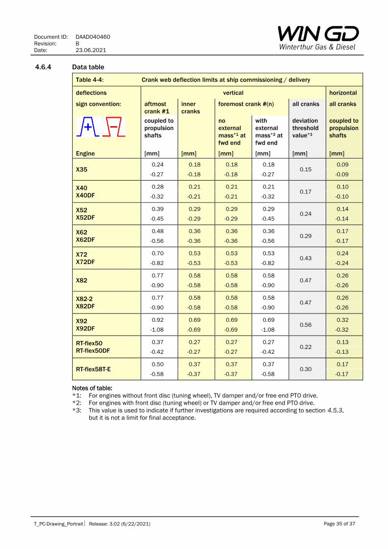
Document ID: DAAD040460
Revision: B
Date: 23.06.2021
T_PC-Drawing_Portrait Release: 3.02 (6/22/2021) Page 35 of 37
4.6.4 Data table
Table 4-4: Crank web deflection limits at ship commissioning / delivery
deflections vertical horizontal
sign convention: aftmost
crank #1
inner
cranks
foremost crank #(n) all cranks all cranks
coupled to
propulsion
shafts
no
external
mass*1 at
fwd end
with
external
mass*2 at
fwd end
deviation
threshold
value*3
coupled to
propulsion
shafts
Engine [mm] [mm] [mm] [mm] [mm] [mm]
X35 0.24 0.18 0.18 0.18
0.15 0.09
-0.27 -0.18 -0.18 -0.27 -0.09
X40
X40DF
0.28 0.21 0.21 0.21 0.17
0.10
-0.32 -0.21 -0.21 -0.32 -0.10
X52
X52DF
0.39 0.29 0.29 0.29 0.24
0.14
-0.45 -0.29 -0.29 -0.45 -0.14
X62
X62DF
0.48 0.36 0.36 0.36 0.29
0.17
-0.56 -0.36 -0.36 -0.56 -0.17
X72
X72DF
0.70 0.53 0.53 0.53 0.43
0.24
-0.82 -0.53 -0.53 -0.82 -0.24
X82 0.77 0.58 0.58 0.58
0.47 0.26
-0.90 -0.58 -0.58 -0.90 -0.26
X82-2
X82DF
0.77 0.58 0.58 0.58 0.47
0.26
-0.90 -0.58 -0.58 -0.90 -0.26
X92
X92DF
0.92 0.69 0.69 0.69 0.56
0.32
-1.08 -0.69 -0.69 -1.08 -0.32
RT-flex50
RT-flex50DF
0.37 0.27 0.27 0.27 0.22
0.13
-0.42 -0.27 -0.27 -0.42 -0.13
RT-flex58T-E 0.50 0.37 0.37 0.37
0.30 0.17
-0.58 -0.37 -0.37 -0.58 -0.17
Notes of table:
*1: For engines without front disc (tuning wheel), TV damper and/or free end PTO drive.
*2: For engines with front disc (tuning wheel) or TV damper and/or free end PTO drive.
*3: This value is used to indicate if further investigations are required according to section 4.5.3,
but it is not a limit for final acceptance.

Document ID: DAAD040460
Revision: B
Date: 23.06.2021
T_PC-Drawing_Portrait Release: 3.02 (6/22/2021) Page 36 of 37
4.7 Crank web deflection limits for normal ship service
Crank web deflection measurements in normal ship service are carried out according to section 1.4.
Information on crank web deflection measurements, recordings and evaluations is provided in
sections 1.3.3, 4.2 and 4.3.
4.7.1 Referred conditions
The crank web deflection limits for normal ship service, given in Table 4-5 below, refer to the general
measurement conditions specified in section 3.3.2 and are additional to the same conditions as
specified in section 3.9.1 for the minimum limits for static loads for normal ship service.
Any deviation therefrom must be added to the measurement records.
4.7.2 Validity
The crank web deflection limits for normal ship service apply to the conditions specified above.
In addition, they can also be applied to measurements made at full draught condition at ship
commissioning / delivery.
However, if the ship has not been at sea before, then the tolerance range must not be fully exploited.
In such cases, reserves are needed to avoid the development of inadmissible values due to
subsequent settling effects and the release of welding stress.
The crank web deflection limits for normal ship service do not apply to the following measurements:
1. on test bed
2. before chocking
3. at ship commissioning / delivery at light ballast or ballast draught condition

Document ID: DAAD040460
Revision: B
Date: 23.06.2021
T_PC-Drawing_Portrait Release: 3.02 (6/22/2021) Page 37 of 37
4.7.3 Data table
Table 4-5: Crank web deflection limits for normal ship service
deflections vertical horizontal
sign convention: aftmost
crank #1
inner
cranks
foremost crank #(n) all cranks
coupled to
propulsion
shafts
no
external
mass*1 at
fwd end
with
external
mass*2 at
fwd end
coupled to
propulsion
shafts
Engine [mm] [mm] [mm] [mm] [mm]
X35 0.27 0.19 0.19 0.19 0.09
-0.27 -0.19 -0.19 -0.27 -0.09
X40
X40DF
0.32 0.23 0.23 0.23 0.11
-0.32 -0.23 -0.23 -0.32 -0.11
X52
X52DF
0.45 0.32 0.32 0.32 0.15
-0.45 -0.32 -0.32 -0.45 -0.15
X62
X62DF
0.56 0.40 0.40 0.40 0.18
-0.56 -0.40 -0.40 -0.56 -0.18
X72
X72DF
0.82 0.58 0.58 0.58 0.27
-0.82 -0.58 -0.58 -0.82 -0.27
X82 0.90 0.64 0.64 0.64 0.29
-0.90 -0.64 -0.64 -0.90 -0.29
X82-2
X82DF
0.90 0.64 0.64 0.64 0.29
-0.90 -0.64 -0.64 -0.90 -0.29
X92
X92DF
1.08 0.76 0.76 0.76 0.35
-1.08 -0.76 -0.76 -1.08 -0.35
RT-flex50
RT-flex50DF
0.42 0.30 0.30 0.30 0.14
-0.42 -0.30 -0.30 -0.42 -0.14
RT-flex58T-E 0.58 0.41 0.41 0.41 0.19
-0.58 -0.41 -0.41 -0.58 -0.19
Notes of table:
*1: For engines without front disc (tuning wheel), TV damper and/or free end PTO drive.
*2: For engines with front disc (tuning wheel) or TV damper and/or free end PTO drive.

DISCLAIMER
© Copyright by Winterthur Gas & Diesel Ltd. All rights reserved. No part of this document may be reproduced or copied in any form or by any means (electronic, mechanical, graphic, photocopying, recording, taping or other information retrieval systems) without the prior written permission of the copyright owner. THIS PUBLICATION IS DESIGNED TO PROVIDE AN ACCURATE AND AUTHORITATIVE INFORMATION WITH REGARD TO THE SUBJECT-MATTER COVERED AS WAS AVAILABLE AT THE TIME OF PRINTING. HOWEVER, THE PUBLICATION DEALS WITH COMPLICATED TECHNICAL MATTERS SUITED ONLY FOR SPECIALISTS IN THE AREA, AND THE DESIGN OF THE SUBJECT-PRODUCTS IS SUBJECT TO REGULAR IMPROVEMENTS, MODIFICATIONS AND CHANGES. CONSEQUENTLY, THE PUBLISHER AND COPYRIGHT OWNER OF THIS PUBLICATION CAN NOT ACCEPT ANY RESPONSIBILITY OR LIABILITY FOR ANY EVENTUAL ERRORS OR OMISSIONS IN THIS BOOKLET OR FOR DISCREPANCIES ARISING FROM THE FEATURES OF ANY ACTUAL ITEM IN THE RESPECTIVE PRODUCT BEING DIFFERENT FROM THOSE SHOWN IN THIS PUBLICATION. THE PUBLISHER AND COPYRIGHT OWNER SHALL UNDER NO CIRCUMSTANCES BE HELD LIABLE FOR ANY FINANCIAL CONSEQUENTIAL DAMAGES OR OTHER LOSS, OR ANY OTHER DAMAGE OR INJURY, SUFFERED BY ANY PARTY MAKING USE OF THIS PUBLICATION OR THE INFORMATION CONTAINED HEREIN. Winterthur Gas & Diesel Ltd. Schützenstrasse 3 Tel. +41 (0)52 264 8844
Winterthur Gas & Diesel AG. PO Box 414, CH-8401 Fax +41 (0)52 264 8866
Winterthur Gas & Diesel S.A. Winterthur, Switzerland
WinGD-2S - Alignment Instruction Marine Propulsion TRACK CHANGES
DATE SUBJECT DESCRIPTION
2016-10-25 DOCUMENT First web upload
2019-06-24 DAAD040460 New revision as merge of DAAD040460-/461-/463-/465-/466-/467
2021-07-16 DAAD040460 Document – new revision