
Energy Harnessing Speed Hump -...
28
Energy Harnessing Speed Hump ME 4041 - Group 4: Daniel Domanico Colby Yarbrough Adnan Hossain 26 April 2013
-
Upload
nguyencong -
Category
Documents
-
view
217 -
download
0
Transcript of Energy Harnessing Speed Hump -...

Energy Harnessing Speed Hump
ME 4041 - Group 4: Daniel Domanico Colby Yarbrough Adnan Hossain
26 April 2013
Energy Harnessing Speed Hump ME 4041
1
Table of Contents
INTRODUCTION......................................................................................................................... 2
OBJECTIVE................................................................................................................................... 2
MODELING .................................................................................................................................. 3
Premodeling ......................................................................................................................................... 3
Piston Assembly .................................................................................................................................. 4
Support Assembly ............................................................................................................................... 8
Hosing .................................................................................................................................................. 13
Complete Assembly ......................................................................................................................... 17
ANALYSIS ................................................................................................................................... 18
CONCLUSION ............................................................................................................................ 27

Energy Harnessing Speed Hump ME 4041
2
INTRODUCTION Speed humps can be found on roads all around the world. Currently, these humps only
serve to slow down vehicles on the road. Slowing down and traversing the speed humps wastes
the kinetic energy of the car without receiving any energy in return. This project focuses on
converting the everyday speed hump into an energy harnessing speed hump, capable of using the
force exerted by a vehicle passing over the speed hump to generate electricity. This project was
chosen to create an alternative way of harnessing clean sustainable energy from an otherwise
unnoticed device currently deployed in modern day roadways. The energy gathered from the
device can be used in various applications including outdoor lighting and tollbooths.
OBJECTIVE The focus of this project is to collect energy from a vehicle passing over a speed hump
and to use this energy for powering devices such as the following: lighting in a parking lot,
garage doors in residential spaces, and tollbooth gates. This device was developed to help society
become more sustainable and environmentally friendly. The idea for this device originally was
derived from potential and kinetic energy principles in classical mechanics. A solution is to
design an energy harvesting speed hump device. An important challenge in the design process is
to capture the energy efficiently. These losses can range from the major losses due to the length
and material of the piping, and the minor losses associated with valves and fittings. Also some
important factors that will contribute to energy losses are due to friction, heat, and fluid
compressibility. This system includes a series of plates, and each plate displaces a pair of pistons
containing hydraulic fluid. This fluid is forced into another piston acting as a two-way hydraulic
cylinder. One side of the cylinder contains hydraulic fluid and the other side contains air. The
side that contains air is connected to a pneumatic pressure vessel. This stores the compressed air.
The stored air creates electrical energy via a pneumatic-electrical generator. A reliable method to
reset the system after a car traverses the device would be ideal; however, it is currently our
biggest challenge. The key aspects to the design are the valves in the system, which provides a
method of returning the plates to their initial positions by supplying a negative pressure in the
pistons. Many factors go into the spring design such as coil diameter, spring life, spring constant,
and estimated displacement. A scaled prototype, CAD model, and Simulink model will assist in
the proof of concept, and provide a solid basis for material and stress analysis.
Energy Harnessing Speed Hump ME 4041
3
MODELING
Premodeling
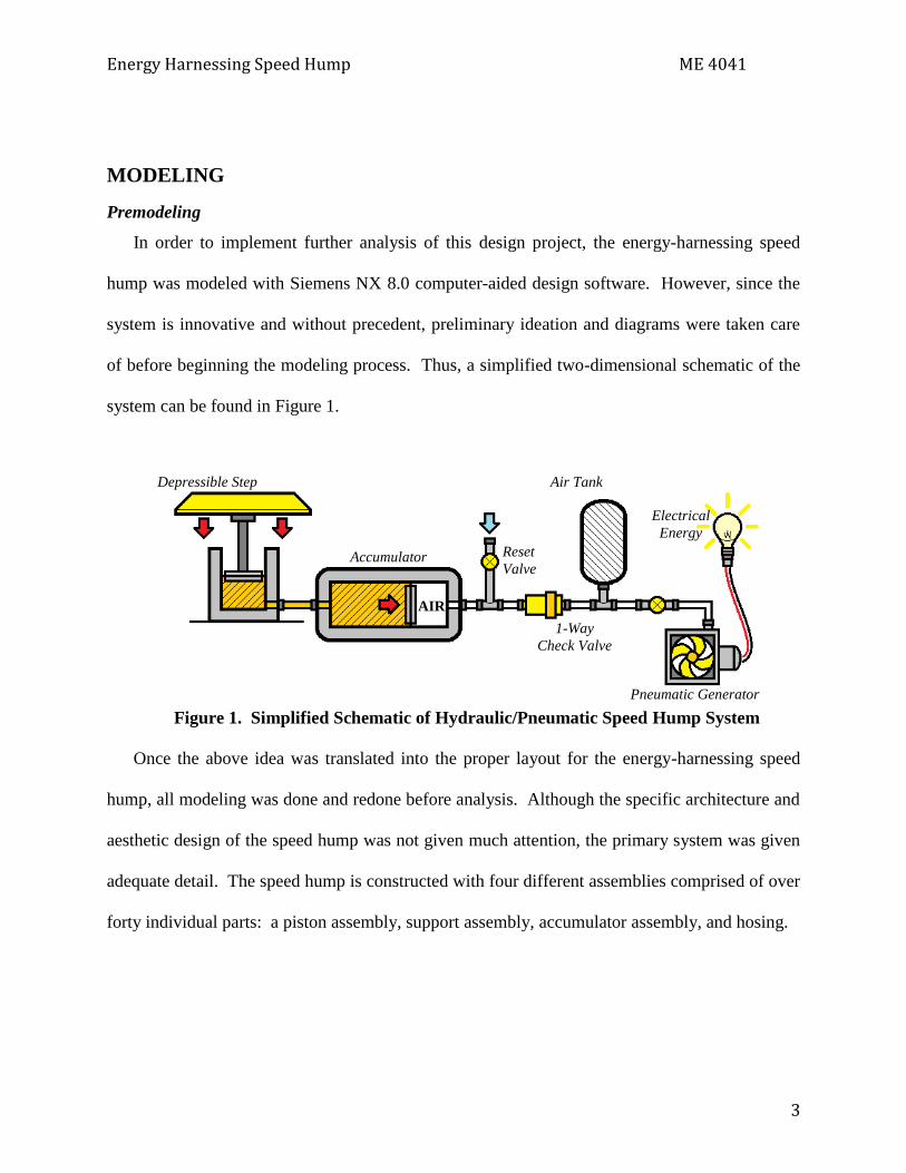
In order to implement further analysis of this design project, the energy-harnessing speed
hump was modeled with Siemens NX 8.0 computer-aided design software. However, since the
system is innovative and without precedent, preliminary ideation and diagrams were taken care
of before beginning the modeling process. Thus, a simplified two-dimensional schematic of the
system can be found in Figure 1.
Figure 1. Simplified Schematic of Hydraulic/Pneumatic Speed Hump System
Once the above idea was translated into the proper layout for the energy-harnessing speed
hump, all modeling was done and redone before analysis. Although the specific architecture and
aesthetic design of the speed hump was not given much attention, the primary system was given
adequate detail. The speed hump is constructed with four different assemblies comprised of over
forty individual parts: a piston assembly, support assembly, accumulator assembly, and hosing.
Accumulator
Depressible Step
1-Way
Check Valve
Reset
Valve
Pneumatic Generator
Air Tank
Electrical
Energy
AIR

Energy Harnessing Speed Hump ME 4041
4
Piston Assembly
The piston assembly was the first to be modeled, as it is the trigger to the system. Using a
suitable bore size of five inches, the actual piston and rod assembly were created, as seen in
Figure 2.
Figure 2. Hydraulic Piston and Rod
Similar to a piston and rod within an internal combustion engine, Figure 2 illustrates the
multiple seals and varying cross-sectional diameter of the piston implemented in the design
process. Modeling consisted of a simple circular geometry with mostly extrusions, cuts, and
edge blends. The piston was then secured with proper housing, seen in Figure 3.

Energy Harnessing Speed Hump ME 4041
5
Figure 3. Piston Housing
The housing was formed using a compression cylinder, top plate, bottom plate, and four
housing bolts. A one-inch wall thickness was given to the cylinder, all appropriate mounting
locations were placed around the bottom plate, and the top plate was given a slightly oversized
diameter to relieve pressure. Once the outlet hole for hydraulic fluid was tapped, the housing
was completed. All modeling was done with extrusions, cuts, and edge blends, using simple
circular and square geometry.
The piston assembly was next encased in an accompanying support bracket, providing a
modular capability in consideration of maintenance. This is seen in Figure 4.

Energy Harnessing Speed Hump ME 4041
6
Figure 4. Piston Assembly Support Bracket
This support, made of a simple metal frame with a hard and rubberized landing mat atop, was
designed to dissipate a portion of the force created by a vehicle’s weight. The mat has slit
indentations along two edges for the alignment of the depressible platform.
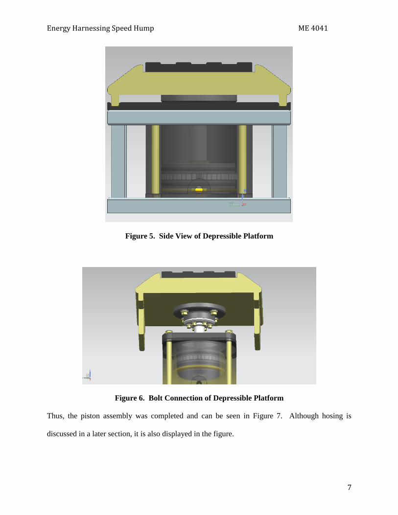
Lastly, the depressible platform itself was designed to perfectly fit atop the piston assembly
and support. It was modeled using extrusions, cuts, chamfers, and edge blends. Its depressed
position and bolting mechanism are displayed in Figures 5 and 6.
Energy Harnessing Speed Hump ME 4041
7
Figure 5. Side View of Depressible Platform
Figure 6. Bolt Connection of Depressible Platform
Thus, the piston assembly was completed and can be seen in Figure 7. Although hosing is
discussed in a later section, it is also displayed in the figure.

Energy Harnessing Speed Hump ME 4041
8
Figure 7. Complete Piston Assembly
Support Assembly
Although not seen in the simplified schematic, the support assembly is bundled along the
piston assembly. It is an assist to failure of the depressible platform. The support assembly is
comprised of two simple springs enclosed similarly to the piston assembly. The spring
assembly, shown in Figure 8, was designed to mimic the exact height of the piston assembly.

Energy Harnessing Speed Hump ME 4041
9
Figure 8. Spring Assembly
The spring assembly was modeled with a basic helix and sweep function, while the top and
bottom hats were created using simply extrusions, cuts, and edge blends. In order to see the
resemblance to the piston assembly, a side view illustration of the full support assembly is shown
in Figure 9.

Energy Harnessing Speed Hump ME 4041
10
Figure 9. Side View of Support Assembly
In contrast to the piston assembly, the support assembly is designed as a four-module
combination with thicker vertical posts. Although not as significant as that of the piston, the
complete support structure must still dissipate a considerable amount of force from a vehicle’s
weight, thus providing a reason for these changes. The inner two modules feature spring
assemblies, whereas the outer two are left for hose organization. The setup of the modules and
an overall view of the support assembly can be found in Figures 9 and 10.

Energy Harnessing Speed Hump ME 4041
11
Figure 9. Four Modules of Support Assembly
Figure 11. Overall View of Support Assembly
Accumulator Assembly
Moving on to the final side of the system, the hydraulic accumulator and pneumatic
generator were modeled based on experimental and hand-written results. The hydraulic
accumulator was simply modeled by extrusions and cuts using the basic square and circular
geometry, and given the same basic cylindrical housing assembly as the piston. Both the inlet
and outlet were tapped to a quarter-inch diameter. The modeling of the hydraulic cylinder was
kept basic for further flow analysis. The component is found in Figure 12.

Energy Harnessing Speed Hump ME 4041
12
Figure 12. Hydraulic Accumulator
As for the pneumatic generator, it was modeled using a more complex geometry. Meshing
was used to create a single surface of each fan blade before extruding the feature radially around
the inner rod. The fan element is housed with both a small inlet and outlet to receive pressurized
air and relieve the housing of pressure. The pneumatic generator can be seen in Figure 13.

Energy Harnessing Speed Hump ME 4041
13
Figure 13. Pneumatic Generator
Although both these components are not clearly seen in the final assembly, they remain housed
at the uppermost level of the speed hump.
Hosing
Once all mechanical aspects of the system were assembled, each component had to be
connected with hosing. The design of the hosing featured a simple quarter-inch inner diameter,
half-inch outer diameter, and varying length depending on the connection. The hoses were
modeled using either simple linear geometry or planar splines before sweeping. One of the used
hoses is shown in Figure 14.

Energy Harnessing Speed Hump ME 4041
14
Figure 14. General Hydraulic Connection Hose
In regards to the ends of each hose connection, simple brass hose ends or one-way check valves
were used, both of which can be seen in Figures 15 and 16.
Figure 15. Hydraulic Hose End Connector

Energy Harnessing Speed Hump ME 4041
15
Figure 16. One-Way Check Valve
The important aspect of hosing is the manner in which the hosing is organized within the system.
Although not shown earlier, the support assembly features hose organization brackets within its
outer two modules. These brackets allow all hydraulic lines to follow the same general path
without overlapping. The hose organizations can be seen in four different views in Figures 17 to
20.
Figure 17. Hose Organization Near Piston Outlet

Energy Harnessing Speed Hump ME 4041
16
Figure 18. Hose Organization to Accumulator Inlet
Figure 19. System Side View of Hose Organization

Energy Harnessing Speed Hump ME 4041
17
Figure 20. Top View of Overall Hose Organization
Complete Assembly
Finally, after all modeling and assembling of the four separate systems was completed, the
assembly of the speed hump was constructed. Although the modeling focuses on the hydraulic
and pneumatic system components, simple ramps were also modeled for visual purposes. Two
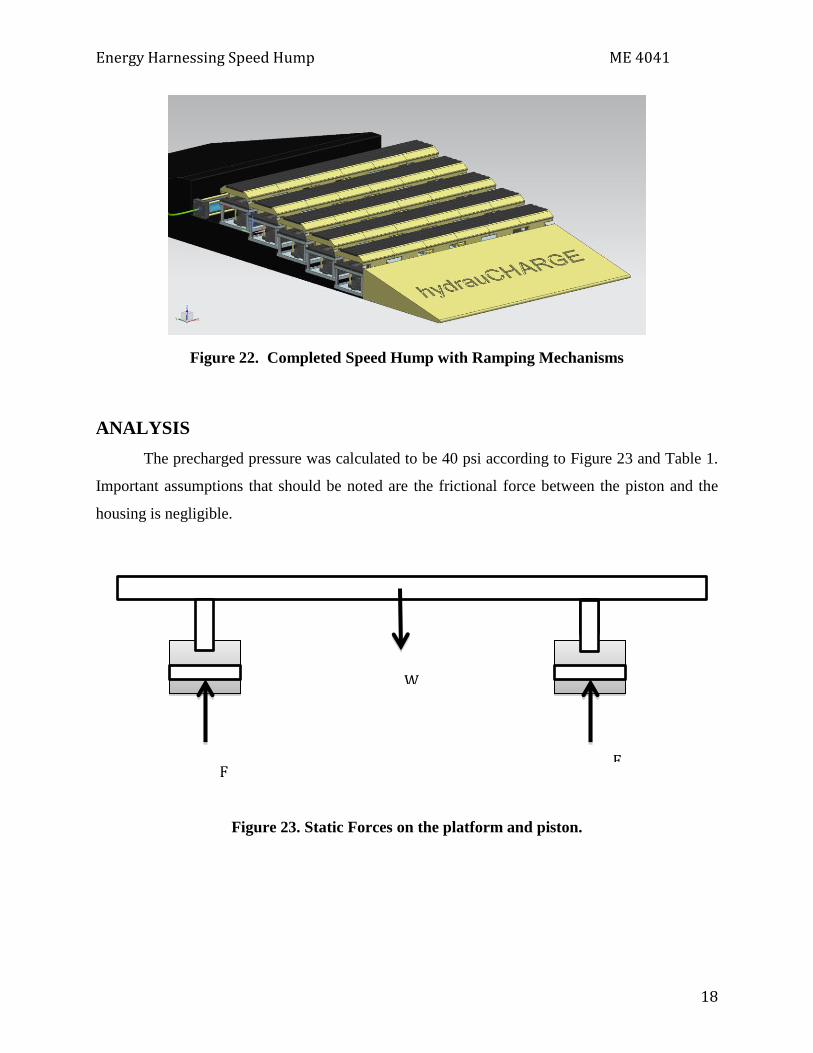
views of the complete system are shown in Figures 21 and 22.
Figure 21. Completed Speed Hump Hydraulic System
Energy Harnessing Speed Hump ME 4041
18
Figure 22. Completed Speed Hump with Ramping Mechanisms
ANALYSIS
The precharged pressure was calculated to be 40 psi according to Figure 23 and Table 1.
Important assumptions that should be noted are the frictional force between the piston and the
housing is negligible.
Figure 23. Static Forces on the platform and piston.
W
F F

Energy Harnessing Speed Hump ME 4041
19
Table 1. Static values for the platform and pistons
Volume of beam 0.0929 m3
Force (weight) 6999 N
F per piston 3499 N
Area of Piston 0.0126 m2
Precharged Pressure 40.3 psi
The maximum stress in the platform was at the outside of the plate that connects the connecting
rod to the platform and is 1.35 Kpsi. The yield strength for steel is around 40 Kpsi, so failure will
not likely occur in the platform. The force applied to the beam was 12000 N.
Figure 24. Von-Mises Nodal Stress
FEA on the piston was first calculated using NX 8. Figure 24 shows the nodal
displacement of the piston with the force exerted by a car. This model was verified using

Energy Harnessing Speed Hump ME 4041
20
where fi is the external load applied to that section, Ki is the spring constant of the section and di
and di+1 are the displacements at the beginning and end of each section respectively.
The maximum displacement was found to be 0.0043 inches in NX. A basic assumption
for the boundary conditions of the piston was that the bottom of the piston was a fixed body. If
the hydraulic fittings burst, the piston would bottom out causing a fixed boundary inside the
piston housing. Since the bottom piston face would no longer have a fluid interface, the stress
and displacement can be assumed to be at a maximum under this condition.
Figure 25. Nodal Displacement of the Piston
The spring constants were calculated using

Energy Harnessing Speed Hump ME 4041
21
where Ai is the cross sectional area, E is the Young’s modulus, and Li is the length of the section.
Since Steel was used, the first equation can be simplified to:
The stress was then analyzed on the piston. As can be seen in Figure 25, the maximum stress is
15.2 Kpsi. So the part will not yield. However the geometry of the piston is of concern because
of fatigue. This is a weak part in the model.
Figure 26. Von-Mises Stress on the piston
The pressure loss was negligible in the first flow analysis of the pipe that connects the piston to
the hydraulic accumulator. The stress is not a large concern in the failure analysis for the model.
However, leaks in fittings are a problematic area. The Reynolds number was calculated to be 534
using

Energy Harnessing Speed Hump ME 4041
22
where V is the velocity, D is the diameter, and ν is the kinematic viscosity. This shows that the
flow is laminar. Also the hydraulic fluid is assumed to be incompressible. And the friction factor
for the pipe was calculated to be 0.12 using
The pressure drop across the pipe that connects the piston to the hydraulic accumulator can be
seen in Figure 26 with the indicated friction factor. This model is very closely related to the first
flow model.
Figure 27. Pressure drop across pipe connecting the hydraulic piston an accumulator
Figure 27 shows the velocity streamlines in the pipe connecting the hydraulic piston and
accumulator. The maximum velocity is located in the centered because of the boundary layer
assumption. The fluid is not fully developed through the entire tube. The length to achieve a fully
developed flow profile is .32 m and the length of the tube is .54 m as
where D is the diameter of the pipe. The flow becomes fully developed before it enters the
hydraulic accumulator.

Energy Harnessing Speed Hump ME 4041
23
Figure 28. Streamline Velocities across pipe connecting the hydraulic piston an
accumulator
Figure 28 shows a simple pressure convergence given the input force on the hydraulic cylinder
and the diameters inside of the cylinder. The pressure from the graph is estimated to be about
1885 psi. Again this model is an ideal model with the same parameters as described above using
the quick convergence may imply an accurate model.
(Pa)
Energy Harnessing Speed Hump ME 4041
24
Figure 29. Fluid pressure convergence for the hydraulic pipe
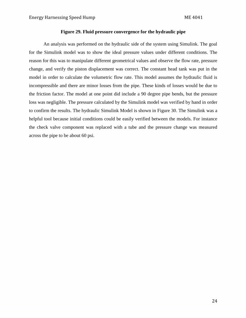
An analysis was performed on the hydraulic side of the system using Simulink. The goal
for the Simulink model was to show the ideal pressure values under different conditions. The
reason for this was to manipulate different geometrical values and observe the flow rate, pressure
change, and verify the piston displacement was correct. The constant head tank was put in the
model in order to calculate the volumetric flow rate. This model assumes the hydraulic fluid is
incompressible and there are minor losses from the pipe. These kinds of losses would be due to
the friction factor. The model at one point did include a 90 degree pipe bends, but the pressure
loss was negligible. The pressure calculated by the Simulink model was verified by hand in order
to confirm the results. The hydraulic Simulink Model is shown in Figure 30. The Simulink was a
helpful tool because initial conditions could be easily verified between the models. For instance
the check valve component was replaced with a tube and the pressure change was measured
across the pipe to be about 60 psi.

Energy Harnessing Speed Hump ME 4041
25
Figure 30. Simulink Model for the Hydraulic side of the System
The pneumatic Simulink model is shown in Figure 31. The pneumatic Simulink model was not
able to converge to a reliable solution for the electricity generated in the system. However, the
model helps conclude the cause for this may be a large amount of heat transfer that occurs in the
system.

Energy Harnessing Speed Hump ME 4041
26
Figure 31. Pneumatic side of the Simulink model
Figure 32. Modeling Process for the Hydraulic Cylinder
The separate fluid domains were constructed using extracted region, trim body, bounded plane,
and sewn.
Energy Harnessing Speed Hump ME 4041
27
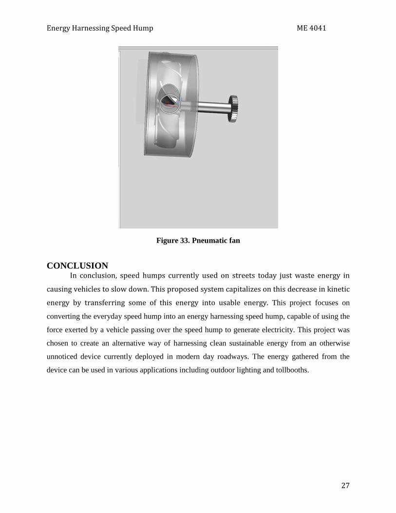
Figure 33. Pneumatic fan
CONCLUSION In conclusion, speed humps currently used on streets today just waste energy in
causing vehicles to slow down. This proposed system capitalizes on this decrease in kinetic
energy by transferring some of this energy into usable energy. This project focuses on
converting the everyday speed hump into an energy harnessing speed hump, capable of using the
force exerted by a vehicle passing over the speed hump to generate electricity. This project was
chosen to create an alternative way of harnessing clean sustainable energy from an otherwise
unnoticed device currently deployed in modern day roadways. The energy gathered from the
device can be used in various applications including outdoor lighting and tollbooths.