A computationally efficient tracker with direct appearance- kinematic ...
ENERGY-EFFICIENT TECHNOLOGY OPTIONS FOR DIRECT …
84
ENERGY-EFFICIENT TECHNOLOGY OPTIONS FOR DIRECT REDUCTION OF IRON PROCESS (SPONGE IRON PLANTS) THE E NERGY AND RESOURCES I NSTITUTE Creating Innovative Solutions for a Sustainable Future
Transcript of ENERGY-EFFICIENT TECHNOLOGY OPTIONS FOR DIRECT …

i
ENERGY-EFFICIENT TECHNOLOGY OPTIONS FOR
DIRECT REDUCTION OF IRON PROCESS(SPONGE IRON PLANTS)
THE ENERGY ANDRESOURCES INSTITUTE
Creating Innovative Solutions for a Sustainable Future

©2021 The Energy and Resources Institute
AuthorsAnanda Mohan Ghosh, Fellow, TERI N Vasudevan, Senior Fellow, TERI Sachin Kumar, Senior Fellow, TERI
ReviewersMr Deependra Kashiva, Executive Director, SIMA
Mr Girish Sethi, Senior Director, TERI
DisclaimerThis document is an output of a research exercise undertaken by TERI for the benefit of the sponge iron-manufacturing sector in India. While every effort has been made to avoid any mistakes of omissions, TERI would not be in any way liable to any persons/ organizations by reason for any mistake/omission in the publication.
Suggested CitationGhosh, A.M., Vasudevan, N. and Kumar, S. 2021. Compendium: Energy-efficient Technology Options for Direct Reduction of Iron Process (Sponge Iron Plants). New Delhi: The Energy and Resources Institute
Published byThe Energy and Resources Institute (TERI)
Darbari Seth Block, IHC Complex, Lodhi Road,
New Delhi – 110003

iii
ENERGY-EFFICIENT TECHNOLOGY OPTIONS FOR
DIRECT REDUCTION OF IRON PROCESS(SPONGE IRON PLANTS)
THE ENERGY ANDRESOURCES INSTITUTE
Creating Innovative Solutions for a Sustainable Future

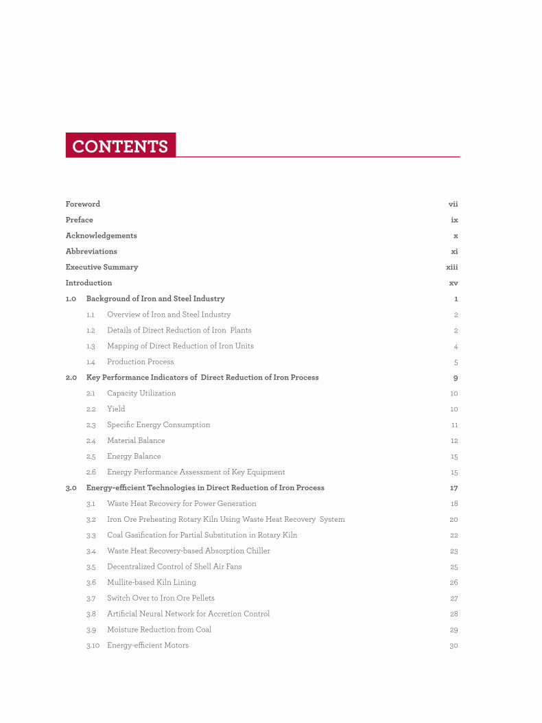
Foreword vii
Preface ix
Acknowledgements x
Abbreviations xi
Executive Summary xiii
Introduction xv
1.0 Background of Iron and Steel Industry 1
1.1 Overview of Iron and Steel Industry 2
1.2 Details of Direct Reduction of Iron Plants 2
1.3 Mapping of Direct Reduction of Iron Units 4
1.4 Production Process 5
2.0 Key Performance Indicators of Direct Reduction of Iron Process 9
2.1 Capacity Utilization 10
2.2 Yield 10
2.3 Specific Energy Consumption 11
2.4 Material Balance 12
2.5 Energy Balance 15
2.6 Energy Performance Assessment of Key Equipment 15
3.0 Energy-efficient Technologies in Direct Reduction of Iron Process 17
3.1 Waste Heat Recovery for Power Generation 18
3.2 Iron Ore Preheating Rotary Kiln Using Waste Heat Recovery System 20
3.3 Coal Gasification for Partial Substitution in Rotary Kiln 22
3.4 Waste Heat Recovery-based Absorption Chiller 23
3.5 Decentralized Control of Shell Air Fans 25
3.6 Mullite-based Kiln Lining 26
3.7 Switch Over to Iron Ore Pellets 27
3.8 Artificial Neural Network for Accretion Control 28
3.9 Moisture Reduction from Coal 29
3.10 Energy-efficient Motors 30
CONTENTS

3.11 Energy-efficient Pumps 32
3.13 Variable Frequency Drives for Air Compressors 33
3.14 Fibre-reinforced Plastic Blades for Cooling Tower Fans 34
3.15 Thermostatic Controller For Cooling Tower 35
3.16 Automatic Power Factor Controller 36
4.0 Potential Low-carbon Technology Options for Indian Direct Reduction of Iron Sector 37
4.1 Direct Reduction of Iron Production Using Solid Coal 39
4.2 Direct Reduction of Iron Production Using Coal Gasification 43
4.3 Direct Reduction of Iron Production Using Gas Route 49
4.4 Hydrogen Use in Indian Iron and Steel Sector 54
5.0 Conclusion 57
Technology Vendors – Energy-efficient Equipment and Systems 60
References 65
vii
FOREWORD
TERI’s analysis over the past few years brings to fore the central role of the industry sector in India’s long-term low-carbon strategy. In 2019–20, we undertook an in-depth study of the Indian steel sector and brought out a comprehensive report— Towards a Low-carbon Steel Sector: Overview of the Changing Market, Technology and Policy Context for Indian Steel. The report outlines various options to reduce the emissions from a rapidly growing steel sector. The report highlights that hydrogen-based steel production is likely to play a major role in the medium to long term. However, it also emphasizes that there is a lot that can be done in near term to reduce the energy consumption from the steel sector. This holds true not just for integrated steel plants but also in the highly disaggregated sponge iron sector, which is dominated by small-sized coal-based direct reduction of iron (DRI)-based plants.
India is one of the unique countries in the world where coal-based DRI route contributes to nearly 20% of the total steel capacity in the country. The prominence of DRI route in the country is primarily attributed to easier availability of non-coking coal, relatively lower investment costs, and limited access to natural gas, which is the preferred option in many developed countries. As a result, there are close to 300 low-capacity DRI plants (100 tonnes per day or less) that use non-coking coal as a primary fuel and have low levels of energy efficiency. It is in this context that, TERI has now developed a compendium focusing only on the DRI sector. This technology
compendium can act as a ready reckoner and provides techno-economic details of appropriate energy-efficient technologies that can be adopted by the coal-based DRI industries in the short term. The adoption of these technological options can help the DRI units improve their energy and environmental performance.
The compendium also gives a brief account of the potential and futuristic technologies such as coal gasification and hydrogen-based processes, which are either fully commercial or under the development stage globally. Compilation of information on these technologies will help key stakeholders make informed decisions in terms of the routes that they need to follow as they expand their plant capacities to meet the rising steel demand.
I hope that this compendium will help in enhancing the knowledge base of the industry as it charts new pathways for a low-carbon future.
Dr Vibha Dhawan Director General, TERI

ix
PREFACE
India is the largest producer of direct reduction of iron (DRI), popularly known as sponge iron and accounted for about 39.3% of the global production in 2020. India’s growing economy will require an increase in steel production to meet the demands of sectors such as housing and infrastructure, automobile, engineering, etc. This demand cannot be met entirely through conventional Blast Furnace-Basic Oxygen Furnace (BF-BOF) route, given high investment costs and limited availability of coking coal for this route. The DRI industry has, therefore, a critical role to play in augmenting India’s future steel production to meet its growing demand.
Like its global compatriots, the steel industry in India is facing the challenges of reducing carbon emissions and improving energy as well as resource
efficiency. Both coal- and gas-based DRI plants are operational in India. However, the share of coal-based DRI production is quite substantial and in comparison to gas-based production, this route is energy- and carbon-intensive. To meet the DRI production target of 80 million tonne by 2030–31 as envisaged under the National Steel Policy (2017), whilst improving the industry’s energy and environmental impact, adopting energy-efficient and innovative low-carbon technologies will be essential.
The Sponge Iron Manufacturers Association (SIMA) acts as an apex body to promote and protect the growing needs of the industry and plays a vital role in bringing together the DRI industry, the Government of India (GOI), and other regulatory bodies. SIMA has contributed towards the comprehensive survey of the Indian Sponge Iron Industry in 2019–20, which was undertaken by the Joint Plant Committee set up under the aegis of the Ministry of Steel (GOI). The Association provides a platform for knowledge sharing and exchange, giving details on technological developments and innovations in manufacturing, energy, environment, and other related issues to the industry.
This technology compendium prepared jointly by TERI and SIMA will be an important source of information on the techno-economic aspects of suitable energy-efficient technologies that can be adopted by DRI units. SIMA members–major sponge iron producers and regional associations–will gain from the detailed information provided in this compendium. Information on new technologies such as coal gasification and hydrogen-based processes will also provide an insight into global technology developments and prospects and growth possibilities for the industry in India.
The compendium brings together valuable information in an accessible format. I am sure that the stakeholders in the DRI sector will benefit immensely from this publication.
Deependra Kashiva,Executive Director
Sponge Iron Manufacturers Association (SIMA)

We would like to extend our sincere thanks to the Sponge Iron Manufacturers Association (SIMA) for encouraging us to bring out this joint publication. Special thanks to Mr Deependra Kashiva, Executive Director, SIMA for contributing to the preparation and review of the report. We are also extremely grateful to Popuri Engineering, especially Mr N Krishna (Director, Technical) and Mr G V Subramanyam (Technical Advisor) for providing useful guidance in shaping the document with relevant energy-efficient-technologies options for the coal-based DRI sector. We would like to extend our sincere thanks to Mr A Kesava Babu, sectoral expert for reviewing and helping us in finalizing the document. We also acknowledge the contribution of our colleagues—Mr Will Hall and Ms Sneha Kashyap—who provided useful information and participated in many internal discussions with regard to this compendium.
We sincerely acknowledge Mr Rakesh Kothari, Director, Kamachi Industries for allowing us to visit their coal-based DRI plant located at Gummidipoondi, Tamil Nadu. We also express our profound gratitude to Mr N Umashankar, General Manager, Operations and Mr G Chandrasekhar, Assistant General Manager, E&I for sharing useful process details and operating parameters along with their experiences in energy-efficiency improvements of their plant. These insights proved invaluable in developing the contents of this document.
The Energy and Resources Institute (TERI) also acknowledges the support provided by Shakti Sustainable Energy Foundation (SSEF). Their support was vital in kick-starting the conversation on a low carbon transition for the Indian iron and steel sector.
ACKNOWLEDGEMENTS

xi
ABC After-burning Chamber
AHU Air-handling Unit
ANN Artificial Neural Network
APFC Automatic Power Factor Controller
ATM Atmosphere (Unit for Pressure Measurement)
BEP Best Efficiency Point
BF Blast Furnace
BOF Basic Oxygen Furnace
CDRI Cold Direct Reduced Iron
CLO Calibrated Lump Ore
CO Carbon Monoxide
COP Coefficient of Performance
DRC Davy Reduction Corporation
DRI Direct Reduction of Iron
EAF Electric Arc Furnace
EIF Electric Induction Furnace
ESP Electrostatic Precipitator
FeO Ferrous Oxide
Fe2O3 Hematite
Fe3C Iron Carbide
FRP Fibre-reinforced Plastic
Gcal Gigacalorie
H2 Hydrogen
HBI Hot-briquetted Iron
HDRI Hot Direct-reduced Iron
HP Horsepower
ABBREVIATIONS

xii
HVAC Heating, Ventilation, and Air Conditioning
ID Induced Draft
KPI Key Performance Indicator
LoI Loss on Ignition
Mt Million Tonne
Mtpa Million Tonne Per Annum
NG Natural Gas
ODP Ozone Depletion Potential
OSIL Orissa Sponge Iron Limited
PAT Perform, Achieve and Trade
PCC Post-combustion Chamber
PID Proportional Integral Derivative
PLC Programmable Logic Control
RPM Rotations Per Minute
SEC Specific Energy Consumption
SIIL Sponge Iron India Limited
TOE Tonne of Oil Equivalent
TDR Tisco Direct Reduction
tpd Tonne Per Day
tph Tonne Per Hour
tpy Tonne Per Year
TR Tonne of Refrigeration
VAM Vapour Absorption Machine
VFD Variable Frequency Drive
WHR Waste Heat Recovery
WSA World Steel Association

xiii
Direct reduction of iron (DRI) forms an important sub-sector of the Indian steel sector, accounting for about 33% of the total steel production, which is about 34.15 million tonne of steel produced in 2020-21. The substantial growth of DRI sector in India can be mainly attributed to the easy availability of non-coking coal and limited access to natural gas. This has led to the establishment of around 300 low-capacity DRI plants using non-coking coal available in the country with an average capacity utilization of 60%. The coal-based DRI kilns in India suffer from low-energy efficiency (about 37%) due to high-energy losses through off-gases (41%). However, a large number of DRI plants with installed capacity of 200 tonne per day (tpd) or more have mostly installed waste heat recovery (WHR)-based power generation systems. This has not only helped in meeting the internal electricity needs but also led to additional energy credit of about 40%, thereby lowering the overall specific energy consumption in DRI production. Further, the excess power generation from WHR system, which is about 60%, helps in generating additional revenues for the plants.
One of the key performance indicators of coal-based DRI plants is the specific energy consumption (SEC) in DRI production, which is observed to be in the range of 4.10–5.26 gigacalorie (Gcal) per tonne DRI. An analysis of input thermal energy utilization clearly indicates that there is significant scope for energy-efficiency improvements by employing feasible WHR system. The WHR-based power generation, the most attractive among all, is economically viable for plants with capacity of 200 tpd and above. Smaller capacity plants of 100 tpd or less can adopt other WHR options such as iron ore preheating and coal drying for improving their energy performance. Adoption of plant-specific energy-efficiency options, for instance switch over to iron ore pellets, artificial neural network for accretion control, decentralized variable frequency drive (VFD) for shell air fans, would help in reducing the SEC level by as high as 2.3 Gcal/t-DRI.
This technology compendium provides techno-economic details for a range of energy-efficient technologies for rotary kiln-based DRI industries. It will enable DRI industries to select and implement the technologies based on their prioritization. The compendium also discusses the potential of futuristic technologies such as coal gasification and hydrogen-based processes, which are either already commercialized or under development to enable their adoption in the future.
EXECUTIVE SUMMARY


xv
Steel is the most important component for infrastructure development of a country. It facilitates growth of the building sector that drives urbanization, in addition to supplementing machinery and tools, which are inseparable from industrialization. The contribution of steel sector to a country’s GDP is well known. It has been observed that no country has achieved high levels of per capita income without substantially raising its per capita steel consumption. India’s steel consumption per capita is still very low and during 2019 it was 74 kg, much less than the world average of 224.5 kg (MoS, 2020). This is a clear indication of the large growth in steel consumption required to raise Indian GDP per capita and improve the welfare of its citizens.
With demand for steel expected to grow rapidly in the years to come, various options for modernizing existing capacity and building new capacity require thoughtful consideration. While considering both these options, it is imperative to prioritize the competitiveness of these facilities, not only for today but also in the long term. To achieve this, it is important to ensure that green field steel plants are ‘future-proofed’ to address tomorrow’s challenges as the campaign life in iron and steel sector are exceptionally long.
One of the biggest challenges—over the long term—is to bring down carbon dioxide emissions from the Indian iron and steel sector. Through deploying advanced energy-efficiency measures in the existing steel capacity, carbon dioxide emissions can be significantly reduced. This is especially true in the context of coal-based direct reduction iron-manufacturing plants (sponge iron plants), which provide a significant scope for energy-efficiency improvements. Most coal-based direct reduction plants are relatively smaller in capacities when compared to the larger integrated steel plants.
Whilst energy-efficiency measures are of vital importance in the near term to help reduce costs and the environmental impact of the sector, over the medium to long term, the sector will need to adopt new low-carbon technologies. This will require a shift from using solid coal in rotary kilns, which is dominant today, towards gas-based technologies, which can substantially reduce the environmental impact. In the near term, based on economic considerations, this could include using syngas, produced via coal gasification, or natural gas. The use of both these gases in steel manufacturing is well established in domestic and international markets.
A shift to gas-based technologies can not only reduce environmental impact in the immediate term, but also provide an easier transition towards using hydrogen in the medium to long term, as the costs of green hydrogen is expected to fall in the future. This will ensure that the sponge iron-manufacturing sector remains competitive and continues to be a vital part of the Indian steel sector, even with increased focus on environmental impact and emission reduction measures in the future.
This compendium aims to provide viable options for improving energy efficiency in existing coal-based DRI plants. It also gives an overview of futuristic technologies that highlight the viable options for adoption by DRI industries to decarbonize their operations.
INTRODUCTION


1
BACKGROUND OF IRON AND STEEL INDUSTRY
1

2
1.1 Overview of Iron and Steel IndustrySteel is the product of a large and technologically complex industry with strong forward and backward linkages of material flow. India’s steel industry has reached sufficient levels of maturity regarding technology absorption, product development, and productivity gains. In terms of both production and consumption, India stands second in the world (WSA, 2020). Indian steel industry exists in different sizes—large, medium, and small—with varying degree of vertical and horizontal integration. It is quite heterogeneous and consists of state-of-the-art plants with wide and varied product basket. Steel manufacturing in the country utilizes different routes such as blast furnace–basic oxygen furnace (BF–BOF), coal-based direct reduction (DR), gas-based DR, electric induction furnace (EIF), and electric arc furnace (EAF).
Coal-based DR is unique in the Indian steel sector as it caters mainly to localized steel demands. The uniqueness of DRI technology is driven by the availability of domestic coal reserves, and lack of sufficient domestic natural gas supplies and coking coal in the country. As with any industrializing economy, the steel sector is of vital importance to India’s economy. It contributes around 2% to the country’s GDP and employs around 2.5 million people in the steel and related sectors (MoS, 2019).
1.2 Details of Direct Reduction of Iron PlantsIndia's total annual direct reduction of iron (DRI) capacity was 47.85 million tonne (Mt) in 2020-21, with a production of 34.15 Mt. There are 285 DRI plants in India, majority of which use coal-based rotary kilns. The installed capacity of DRI plants varies in the range of 50–500 tonne per day (tpd) with single or multiple kilns. Most of the DRI plants utilize 100 tpd kilns. The total installed capacity of coal-based DRI plants is 36.74 Mt while that of gas-based DRI plants is 11.10 Mt, with two plants using gasification route (Syngas and COREX gas) and three plants using natural gas route supplemented by COREX/ coke oven gas.

3
Large capacity DRI plants
Plant Capacity (Mtpa)
Coal-based DRI plants
Adhunik Metaliks Limited 0.324
Godawari Power and Steel Limited 0.495
Jindal Steel & Power Limited (JSPL), Raigarh 1.370
Lloyds Metals and Energy Limited 0.270
Prakash Industries Limited, Champa 1.000
Rungta Mines 1.390
Sarda Energy and Metals Limited 0.360
Shyam Metallics and Energy Limited, Sambalpur 0.800
Shyam Sel and Power Limited, Jamuria 0.425
Shri Bajrang Power and Ispat Limited 0.360
SMC Power Generation Limited 1.000
Super Smelters Limited–III, Burdwan 0.740
Tata Steel Long Products Limited 1.05
Tata Steel BSL Limited 1.500
Gas-based DRI plants
Arcelor Mittal Nippon Steel Limited, Hazira 5.500
JSPL, Angul 1.800
JSW Steel Limited, Salav, Raigarh 1.000
JSW Steel Limited, Dolvi, Raigarh 1.600
JSW Steel Limited, Vijayanagar 1.200
4
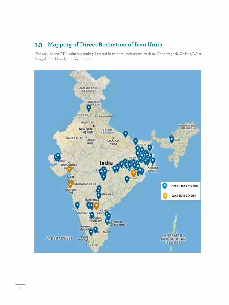
1.3 Mapping of Direct Reduction of Iron UnitsThe coal-based DRI units are mainly located in mineral-rich states such as Chhattisgarh, Odisha, West Bengal, Jharkhand, and Karnataka.

5
1.4 Production ProcessDirect reduction of iron can be defined as a process in which metallic iron is directly produced by reduction of iron ore in solid state at temperature below the melting point of iron. The reduction of iron ore can be achieved using either carbon-bearing material, such as non-coking coal, or a suitable reducing gas in the form of reformed natural gas. The reducing gas in DRI process mainly consists of hydrogen and carbon monoxide. The iron thus produced in solid state is known as direct reduced iron. The DRI resembles a honeycomb structure, which looks spongy in texture when viewed in microscope and hence is also called ‘sponge iron’. The DRI plants in India follow one of the practices to obtain reductants as hydrogen or carbon monoxide in the reduction process from solid coal, coal gasification, or natural gas.
1.4.1 Direct Reduction of Iron Production Using Solid Coal
Most of the coal-based DRI production in India has customized plant specifications, using one of the standard DRI processes such as SL/RN, KRUPP-REIN, KRUPP-CODIR, DRC (DAVY Reduction Corporation), ACCAR, DRC, or customized such as TDR (TISCO Direct Reduction), SIIL (Sponge Iron India Limited), JINDAL, OSIL (Orissa Sponge Iron Limited), and Popuri Engineering Limited. The solid coal-based DRI production uses horizontal rotary kiln in production processes. The kiln is provided with an inside refractory lining of 150–200 mm to protect the shell and has a slope of 2.5%–3.0% towards the discharge end. The combustion air requirement for the feed is provided by air blowers along the length of the heating zone. The major raw materials used in sponge iron production include iron ore (hematite or Fe2O3), non-coking coal, and limestone/dolomite. Hematite, which is rich in iron content of 65% or more is preferred in sponge iron plants. Iron ore can be used in the form of lumps and pellets. Most of the DRI plants in India employ smaller capacity rotary kilns (100 tpd or less).
A DRI plant
6
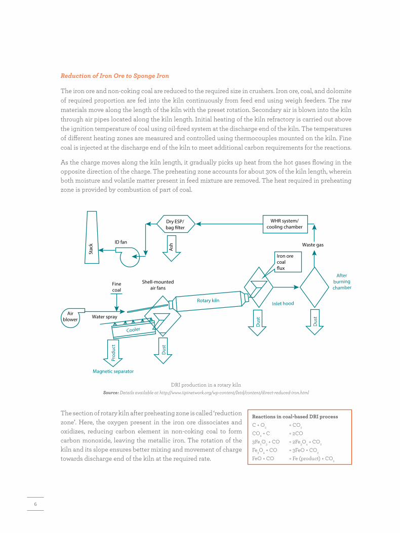
Reduction of Iron Ore to Sponge Iron
The iron ore and non-coking coal are reduced to the required size in crushers. Iron ore, coal, and dolomite of required proportion are fed into the kiln continuously from feed end using weigh feeders. The raw materials move along the length of the kiln with the preset rotation. Secondary air is blown into the kiln through air pipes located along the kiln length. Initial heating of the kiln refractory is carried out above the ignition temperature of coal using oil-fired system at the discharge end of the kiln. The temperatures of different heating zones are measured and controlled using thermocouples mounted on the kiln. Fine coal is injected at the discharge end of the kiln to meet additional carbon requirements for the reactions.
As the charge moves along the kiln length, it gradually picks up heat from the hot gases flowing in the opposite direction of the charge. The preheating zone accounts for about 30% of the kiln length, wherein both moisture and volatile matter present in feed mixture are removed. The heat required in preheating zone is provided by combustion of part of coal.
ID fan
Stac
k
Dus
t
Dus
t
Prod
uct
Cooler
Inlet hood
Afterburningchamber
Magnetic separator
Dus
t
Dry ESP/bag filter
Ash Waste gas
Iron orecoalflux
Airblower Water spray
Finecoal
Shell-mountedair fans
WHR system/cooling chamber
Rotary kiln
DRI production in a rotary kilnSource: Details available at http://www.iipinetwork.org/wp-content/Ietd/content/direct-reduced-iron.html
The section of rotary kiln after preheating zone is called ‘reduction zone’. Here, the oxygen present in the iron ore dissociates and oxidizes, reducing carbon element in non-coking coal to form carbon monoxide, leaving the metallic iron. The rotation of the kiln and its slope ensures better mixing and movement of charge towards discharge end of the kiln at the required rate.
Reactions in coal-based DRI processC + O2 = CO2
CO2 + C = 2CO3Fe2O3 + CO = 2Fe3O4 + CO2
Fe3O4 + CO = 3FeO + CO2
FeO + CO = Fe (product) + CO2

7
A temperature of about 900–1050°C is maintained in the reduction zone. The higher the temperature, the faster would be the oxygen removal from hematite. The reduction of iron ore occurs in solid state with the critical factor being ‘controlled combustion of coal’ towards formation of carbon monoxide (Boudouard reaction which is endo-thermic). The residence time for iron ore inside the kiln is about 8–10 hours to form metallic iron. The quality of sponge iron is measured in terms of metallization, which is the ratio of metallic iron to total iron present in sponge iron.
Cooling of Sponge Iron
The sponge iron and solid waste discharge (comprising char, spent limestone/ dolomite) are transferred to water-cooled rotary cooler. The rotary cooler is sloped at about 2.5%–3%. Water is sprayed on outer shell of rotary cooler to indirectly reduce the temperature of kiln discharge to about 100–120°C. This helps in avoiding re-oxidation of sponge iron on exposure to atmosphere as it is quite unstable at high temperatures.
Electro-magnetic Separation and Screening
The discharge material from the rotary cooler is transferred through conveyors for screening of fines and coarse materials. The discharge material of grain size less than 3 mm is separated out and passed through an electro-magnetic separator, wherein sponge iron is separated from char and other impurities. The sponge iron is screened in size fraction to separate lumps and fines.
The off-gases generated from the rotary kiln flow in counter current direction to input charge leave from feed input end of the rotary kiln and pass through a gravitational dust settling chamber. It then passes through a post-combustion chamber (PCC) or after-burning chamber (ABC) wherein the remaining carbon monoxide in off-gases is converted into carbon dioxide. The off-gases are either passed through a wet scrubber or combination of gas-conditioning tower in order to reduce off-gases’ temperature to below 150°C. The cooled off-gases are then passed through an electrostatic precipitator (ESP) before being expelled through chimney.
1.4.2 Gas-based Direct Reduction of Iron ProductionGas-based DRI manufacturing process involves: (i) generation and cleaning of the reducing gases such as hydrogen and carbon monoxide using gasification or reforming route as applicable and (ii) iron ore reduction in a vertical shaft furnace. The vertical shaft furnace is the heart of a gas-based DRI process and consists of a cylindrical, refractory-lined vessel. It uses reducing gases from natural gas, syngas from coal, coke oven gas, or exhaust gas from the COREX process.
The shaft furnace works on the principle of counter flow system, wherein the iron ore (burden) moves downwards by gravity and gets reduced by the upward-flowing reducing gases. The iron burden is fed
Heat of reactionsFe2O3 + CO = 2FeO + CO2 − 2.05656 GJ/kmolFeO + CO = Fe + CO2 − 0.25738 GJ/kmolCO2 + C = 2CO + 75.0 GJ/kmol2CO + O2= 2CO2 − 135.71417 GJ/kmolC + O2= CO2 − 97.994248 GJ/kmol2C + O2= 2CO − 3.439722 GJ/kmol2H2+ O2= 2H2O − 29.8268 GJ/kmol
Reactions in a gas-based DRI process
Reactions with H2
3Fe2O3 + H2 = 2Fe3O4 + H2OFe3O4 + H2 = 3FeO + H2OFeO + H2 = Fe + H2O
Reactions with CO3Fe2O3 + CO = 2Fe3O4 + CO2
Fe3O4 + CO = 3FeO + CO2
FeO + CO = Fe + CO2

8
from the top of the kiln and the sponge iron is taken out from the furnace bottom. The syngas is treated to enrich hydrogen and carbon monoxide content after which it is preheated and used in the shaft furnace. The reducing gas is passed through the ore bed, and the spent gas is recirculated after heating and reforming to a mixture of hydrogen and carbon monoxide in a reformer, wherein it is heated to about 950°C to ensure adequate reduction reaction rates.
Since there is no contamination with non-magnetic materials, the gas-based DRI does not require magnetic separation. The gas-based processes are flexible and the final yield can be produced in three different product forms, depending on the specific requirements that include cold DRI, hot-briquetted iron (HBI), or hot DRI. There are mainly three types of gas-based processes that can be utilized in a DRI production: (1) HYL or Energiron process, (2) MIDREX process, and (3) PERED process.
Majority of DRI plants in India utilize solid coal-based route. In light of this fact, this technology compendium mainly focuses on energy-efficient technologies and practices pertaining to rotary kiln-based DRI process using solid coal.

9
KEY PERFORMANCE INDICATORS OF DIRECT REDUCTION OF IRON PROCESS
2

10
2.1 Capacity UtilizationPerformance of the DRI sector largely relies on overall utilization of the installed capacity. It is the ratio of the production to the total installed capacity of DRI. The average capacity utilization of DRI plants from 2014–15 to 2019–20 was 62% (varying from 52% to 74.5%).
02014-15 2015-16 2016-17 2017-18 2018-19 2019-20
10
20
30
40
50
60
Gas Based
Prod
ucti
on a
nd C
apac
ity
(in ‘0
00 to
nne)
Coal Based Total Capacity
Capacity utilization of DRI plantsSource: SIMA (2021)
The capacity utilization of DRI plants can be calculated using the following formula:
2.2 YieldYield of sponge iron is dependent on factors such as tumbler index, abrasion index, and thermal degradation. Level of metallization of iron ore and loss of iron in the process are also determining factors of the yield. The loss of iron can occur through many ways, such as carryover in off-gases, level of accrertion, magnetic separation, inseparable iron loss in char, which depend on the level of fines present in the feed iron ore.
The yield of rotary kiln is the ratio of total sponge iron production to the iron ore fed. It is dependent on iron content, thermal degradation of iron ore, and operating practices. The optimum yield is equal to iron content provided majority of iron ore properties are met to optimum level. Any deviation in yield can be related to loss on ignition and operating practices. Higher the ratio of the sponge iron formed, the higher will be the yield of the process and vice versa for a given feed.
A key performance indicator (KPI) is a measurable parameter that indicates the effectiveness or efficiency of a system. The KPIs specify the potential for performance improvements with respect to the design or best performance values. The KPIs of a direct reduction of iron (DRI) process include capacity utilization, yield, specific energy consumption (SEC), material balance, and energy balance. This section provides the KPIs with respect to the production of direct reduction iron or sponge iron using solid coal in the process.
Yield (%) = x 100Sponge iron production (tonne)
Input iron ore (tonne)
x 100Capacity utilization (%) =Production (tonne/year)
Installed capacity (tonne/year)

11
The maximum yield in a DRI process will be equal to the percentage of iron content in the ore if there are no losses in the process. As an illustration of the best case scenario, about 1.55 tonne of iron ore, with 64% iron content, will produce a maximum of 1 tonne of sponge iron.
2.3 Specific Energy ConsumptionCoal is the principal fuel used in rotary kilns. A share of energy consumption of a coal-based DRI plant shows that about 98% of energy is used as coal for heating and reduction process, while electricity accounts for only 2% of the total energy consumption.
The SEC of a coal-based DRI rotary kiln is defined as the ratio of total energy consumption to the corresponding total production. The SEC is an important KPI that helps evaluate how effectively the DRI plant is performing in terms of energy consumption.
The SEC of a coal-based DRI rotary kiln is defined as the ratio of total energy consumption to the corresponding total production. The SEC is an important KPI that helps evaluate how effectively the DRI plant is performing in terms of energy consumption.
Thermal, 98%
Electrical, 2%
Share of energy consumption
Significant variations in SEC level can be observed in coal-based DRI production. The SEC of coal-based DRI production using rotary kiln varies from 4.10 to 5.26 Gcal/t-DRI (average: 4.51 Gcal/t-DRI ). SEC levels are plant specific and their variations may be attributed to factors such as iron content in iron ore, fixed carbon and volatile matter in coal, temperature profile of kiln, and operating practices. The on-line measurements and control of key operating parameters are vital in optimizing SEC levels in DRI plants.
Illustration of SEC evaluation of rotary kiln
Parameter Unit Value
Sponge iron production tpd 110
Coal consumption tpd 110
Calorific value of coal kcal/kg 5200
Electricity consumption* kWh/t 70
SEC Gcal/t DRI 5.26
* Source of electricity (WHR/captive power plant/grid is ignored in SEC assessment). Source: Plant data
SEC (Gcal/tonne) =Total DRI production (tonne/year)
Total energy consumption (Gcal/year)

12
The plant-level SEC may get reduced under two conditions: (i) if sensible heat in off-gases is recovered, reutilized, or recycled in meeting the energy demands of the plant, and (ii) if dolochar (by-product from rotary kiln) is reused at the plant level. In modern coal-based DRI plants, the off-gases are used for power generation and dolochar is used for additional steam generation, resulting in improved SEC levels. In a 400-tpd DRI plant, heat recovery from off-gases and recovery of coalchar would reduce the SEC levels from 5.20 to 3.19 Gcal/t-DRI production.
Illustration of SEC evaluation of DRI plant
Parameter Unit Value
SEC: before heat recovery Gcal/t 5.20
Heat recovery from off-gases and coal char Gcal/t 2.01
SEC: after heat recovery Gcal/t 3.19
Source: Plant data
It may be noted that a more realistic approach for SEC evaluation would be based on the iron content in sponge iron. For example, the SEC works out to be 5.54 Gcal/t of iron, considering 89% of iron content in sponge iron, calorific value of coal as 5200 kcal/ kg, and coal to iron ratio of 0.95.
2.4 Material BalanceThe input materials to rotary kiln include iron ore, dolomite, and coal. Air is supplied for combustion of coal and to maintain the set temperature along the entire length of the rotary kiln for sustaining reduction reactions towards formation of iron. The output from rotary kiln consists of sponge iron, solid waste discharge, and off-gases. The off-gases formed are passed through after-combustion chamber and transferred to either waste heat recovery (WHR) system, or vented out through chimney as applicable. The typical mass balance is based on 64% yield.
Sponge Iron (4.2 tph)
O�-gas (9.4 tph)
Char (1.2 tph)
Air (3.9 tph)
Iron Ore (6.5 tph)Coal (4.2 tph)
Dolomite (0.2 tph)
Kiln
Mass balance of a coal-based rotary kiln

13
2.5 Energy BalanceThe energy balance considers total energy as input into the process and reveals useful quantity heat (that is, efficiency) and energy losses as output for a specific time period under steady state conditions. The energy consumption is dependent on a few factors, notably quality of raw materials, design of kiln, and operating practices. The assessment of energy balance is based on measurements and analysis of key operating parameters.
Instruments used for performance evaluation
Instrument type Measurement scope
Pitot tube Off-gas velocity
Pyrometer Temperature of furnace and openings
Infrared thermometer Surface temperature
Power analyser Power (active, reactive, apparent), power factor, current, voltage, harmonics
The energy balance of a coal-based rotary kiln indicates that useful heat, that is, heat required for reduction and calcination is about 37%. A major share of heat input is lost in off-gases (41%), which include sensible heat in off-gases and chemical heat due to formation of unburnts such as carbon monoxide and carbon. Further, coal–char formation accounts for nearly 11% of the total heat losses.
2.6 Energy Performance Assessment of Key Equipment2.6.1 Rotary Kiln
The overall performance of a rotary kiln used in a coal-based DRI plant can be assessed considering useful heat required to convert iron ore material into sponge iron in solid state and the net heat generated through endothermic and exothermic reactions. The heat energy is primarily used to increase the temperature of feed material to sustain the reactions to reduce iron ore into iron. Different types of heat losses that can occur in a rotary kiln are listed here:
� Heat loss through off-gases comprising sensible heat and chemical heat (carbon monoxide and unburnt carbon)
O�-gas loss(41.30%)
Moisture loss(0.20%)
Coal (100%) Reactioncalcination
(37%)
Sensible heat inkiln discharge (5.30%)
Char (11%)
Wall loss(5.20%)
Typical energy balance of a coal-based rotary kiln
14
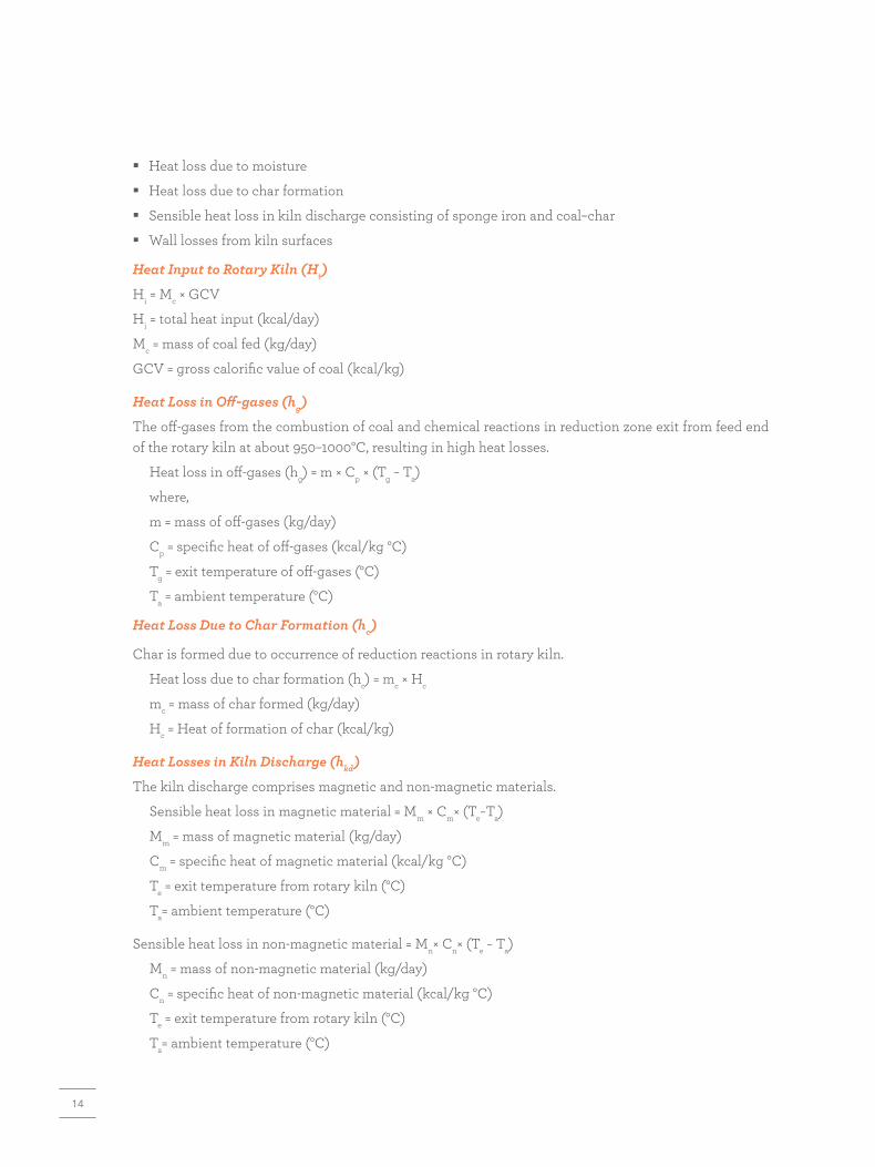
� Heat loss due to moisture
� Heat loss due to char formation
� Sensible heat loss in kiln discharge consisting of sponge iron and coal–char
� Wall losses from kiln surfaces
Heat Input to Rotary Kiln (Hi)
Hi = Mc × GCV
Hi = total heat input (kcal/day)
Mc = mass of coal fed (kg/day)
GCV = gross calorific value of coal (kcal/kg)
Heat Loss in Off-gases (hg)
The off-gases from the combustion of coal and chemical reactions in reduction zone exit from feed end of the rotary kiln at about 950–1000°C, resulting in high heat losses.
Heat loss in off-gases (hg) = m × Cp × (Tg − Ta)
where,
m = mass of off-gases (kg/day)
Cp = specific heat of off-gases (kcal/kg °C)
Tg = exit temperature of off-gases (°C)
Ta = ambient temperature (°C)
Heat Loss Due to Char Formation (hc)
Char is formed due to occurrence of reduction reactions in rotary kiln.
Heat loss due to char formation (hc) = mc × Hc
mc = mass of char formed (kg/day)
Hc = Heat of formation of char (kcal/kg)
Heat Losses in Kiln Discharge (hkd)
The kiln discharge comprises magnetic and non-magnetic materials.
Sensible heat loss in magnetic material = Mm × Cm× (Te−Ta)
Mm = mass of magnetic material (kg/day)
Cm = specific heat of magnetic material (kcal/kg °C)
Te = exit temperature from rotary kiln (°C)
Ta= ambient temperature (°C)
Sensible heat loss in non-magnetic material = Mn× Cn× (Te − Ta)
Mn = mass of non-magnetic material (kg/day)
Cn = specific heat of non-magnetic material (kcal/kg °C)
Te = exit temperature from rotary kiln (°C)
Ta= ambient temperature (°C)
15
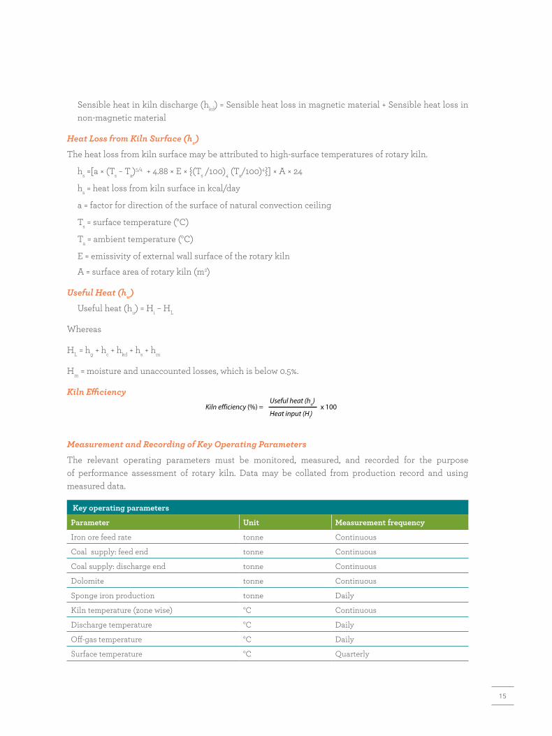
Sensible heat in kiln discharge (hkd) = Sensible heat loss in magnetic material + Sensible heat loss in non-magnetic material
Heat Loss from Kiln Surface (hs)
The heat loss from kiln surface may be attributed to high-surface temperatures of rotary kiln.
hs =[a × (Ts − Ta)5/4 + 4.88 × E × {(Ts /100)4 (Ta/100)4}] × A × 24
hs = heat loss from kiln surface in kcal/day
a = factor for direction of the surface of natural convection ceiling
Ts = surface temperature (°C)
Ta = ambient temperature (°C)
E = emissivity of external wall surface of the rotary kiln
A = surface area of rotary kiln (m2)
Useful Heat (hu)
Useful heat (hu) = Hi – HL
Whereas
HL = hg + hc + hkd + hs + hm
Hm = moisture and unaccounted losses, which is below 0.5%.
Kiln Efficiency
Key operating parameters
Parameter Unit Measurement frequency
Iron ore feed rate tonne Continuous
Coal supply: feed end tonne Continuous
Coal supply: discharge end tonne Continuous
Dolomite tonne Continuous
Sponge iron production tonne Daily
Kiln temperature (zone wise) °C Continuous
Discharge temperature °C Daily
Off-gas temperature °C Daily
Surface temperature °C Quarterly
Measurement and Recording of Key Operating Parameters
The relevant operating parameters must be monitored, measured, and recorded for the purpose of performance assessment of rotary kiln. Data may be collated from production record and using measured data.
Kiln e�iciency (%) = x 100Useful heat (hu)
Heat input (Hi)
16
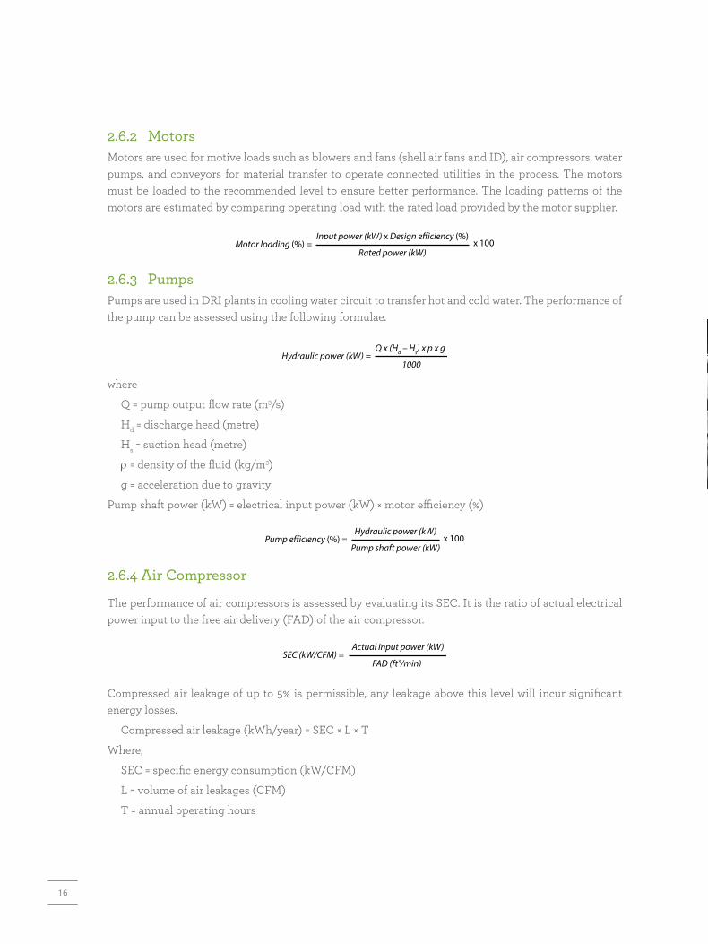
2.6.2 Motors Motors are used for motive loads such as blowers and fans (shell air fans and ID), air compressors, water pumps, and conveyors for material transfer to operate connected utilities in the process. The motors must be loaded to the recommended level to ensure better performance. The loading patterns of the motors are estimated by comparing operating load with the rated load provided by the motor supplier.
2.6.3 PumpsPumps are used in DRI plants in cooling water circuit to transfer hot and cold water. The performance of the pump can be assessed using the following formulae.
where
Q = pump output flow rate (m3/s)
Hd = discharge head (metre)
Hs = suction head (metre)
ρ = density of the fluid (kg/m3)
g = acceleration due to gravity
Pump shaft power (kW) = electrical input power (kW) × motor efficiency (%)
2.6.4 Air Compressor
The performance of air compressors is assessed by evaluating its SEC. It is the ratio of actual electrical power input to the free air delivery (FAD) of the air compressor.
Compressed air leakage of up to 5% is permissible, any leakage above this level will incur significant energy losses.
Compressed air leakage (kWh/year) = SEC × L × T
Where,
SEC = specific energy consumption (kW/CFM)
L = volume of air leakages (CFM)
T = annual operating hours
Motor loading (%) = x 100Input power (kW) x Design e�iciency (%)
Rated power (kW)
Hydraulic power (kW) =Q x (Hd – Hs) x p x g
1000
x 100Hydraulic power (kW)
Pump shaft power (kW)
SEC (kW/CFM) =Actual input power (kW)
FAD (ft3/min)

17
ENERGY-EFFICIENT TECHNOLOGIES IN DIRECT REDUCTION OF IRON PROCESS
3
18
3.1 Waste Heat Recovery for Power Generation3.1.1 Background
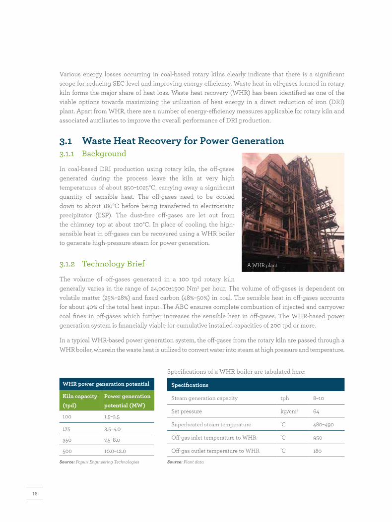
In coal-based DRI production using rotary kiln, the off-gases generated during the process leave the kiln at very high temperatures of about 950–1025°C, carrying away a significant quantity of sensible heat. The off-gases need to be cooled down to about 180°C before being transferred to electrostatic precipitator (ESP). The dust-free off-gases are let out from the chimney top at about 120°C. In place of cooling, the high-sensible heat in off-gases can be recovered using a WHR boiler to generate high-pressure steam for power generation.
3.1.2 Technology Brief
The volume of off-gases generated in a 100 tpd rotary kiln generally varies in the range of 24,000±1500 Nm3 per hour. The volume of off-gases is dependent on volatile matter (25%–28%) and fixed carbon (48%–50%) in coal. The sensible heat in off-gases accounts for about 40% of the total heat input. The ABC ensures complete combustion of injected and carryover coal fines in off-gases which further increases the sensible heat in off-gases. The WHR-based power generation system is financially viable for cumulative installed capacities of 200 tpd or more.
In a typical WHR-based power generation system, the off-gases from the rotary kiln are passed through a WHR boiler, wherein the waste heat is utilized to convert water into steam at high pressure and temperature.
A WHR plant
WHR power generation potential
Kiln capacity (tpd)
Power generation potential (MW)
100 1.5–2.5
175 3.5–4.0
350 7.5–8.0
500 10.0–12.0
Source: Popuri Engineering Technologies
Specifications of a WHR boiler are tabulated here:
Specifications
Steam generation capacity tph 8–10
Set pressure kg/cm2 64
Superheated steam temperature °C 480–490
Off-gas inlet temperature to WHR °C 950
Off-gas outlet temperature to WHR °C 180
Source: Plant data
Various energy losses occurring in coal-based rotary kilns clearly indicate that there is a significant scope for reducing SEC level and improving energy efficiency. Waste heat in off-gases formed in rotary kiln forms the major share of heat loss. Waste heat recovery (WHR) has been identified as one of the viable options towards maximizing the utilization of heat energy in a direct reduction of iron (DRI) plant. Apart from WHR, there are a number of energy-efficiency measures applicable for rotary kiln and associated auxiliaries to improve the overall performance of DRI production.

19
In a typical WHR boiler system, the off-gases first pass through a superheater to increase the temperature of saturated steam to produce superheated steam. From superheater, the hot gases pass through series of boiler bank tubes to produce saturated steam. Upon further losing heat in WHR boiler, the cooled gases enter economizer for preheating feed water. The off-gases transfer a significant portion of sensible heat (about 50%–55%) to WHR boiler system. In this process, the temperature of off-gases gets reduced substantially to about 180°C. The particulates from off-gases are removed in electrostatic precipitator before being let out through the stack.
The turbo-generator system comprises a condensing turbine and an alternator. About 8–10 tph of superheated steam at 64±2 kg/cm2 and 480±10°C is generated. The high-pressure steam is passed through turbo-generator to produce power. In a typical coal-based DRI plant having 2 × 100 tpd kilns, about 4 MW (= 2 × 2 MW) of electricity can be generated using WHR-based power generation system.
WHR-based power generation
A coal-based DRI plants in Tamil Nadu has an installed capacity of 400 tpd, from 4 rotary kilns of 100 tpd each. The plant uses imported coal. Considering the high-sensible heat available with off-gases generated from rotary kilns, the plant has installed WHR system for power generation. The power generation system comprises a WHR boiler for each rotary kiln. The steam generated from all four WHR boilers are combined together in a common header and fed to a turbo-generator which ensures operations under partial load when some of the rotary kilns are under shutdown. The full load power generation capacity of WHR system is 8 MW.
Quantity of off-gases per kiln = 24,000 Nm3/h
Temperature of off-gases = 950°C
Steam generation from one WHR boiler = 10 tph @ 64 kg/cm2 and 485°C
Equivalent power generation per rotary kiln = 2 MW
Electricity available for export = 60%
(internal use consists of 30% for DRI plant and 10% for WHR system)
Feedwater
Economizer
Boiler tubes
SuperheaterElectrostaticprecipitator
Superheated
Steam
To condenser
Steamturbine
WHR BOILER
Alternator
Post-combustion
chamber
~
Stack
Rotary kiln
ID fan
WHR-based power generation
20
3.1.3 Savings, Investments, and Greenhouse Gas Reduction
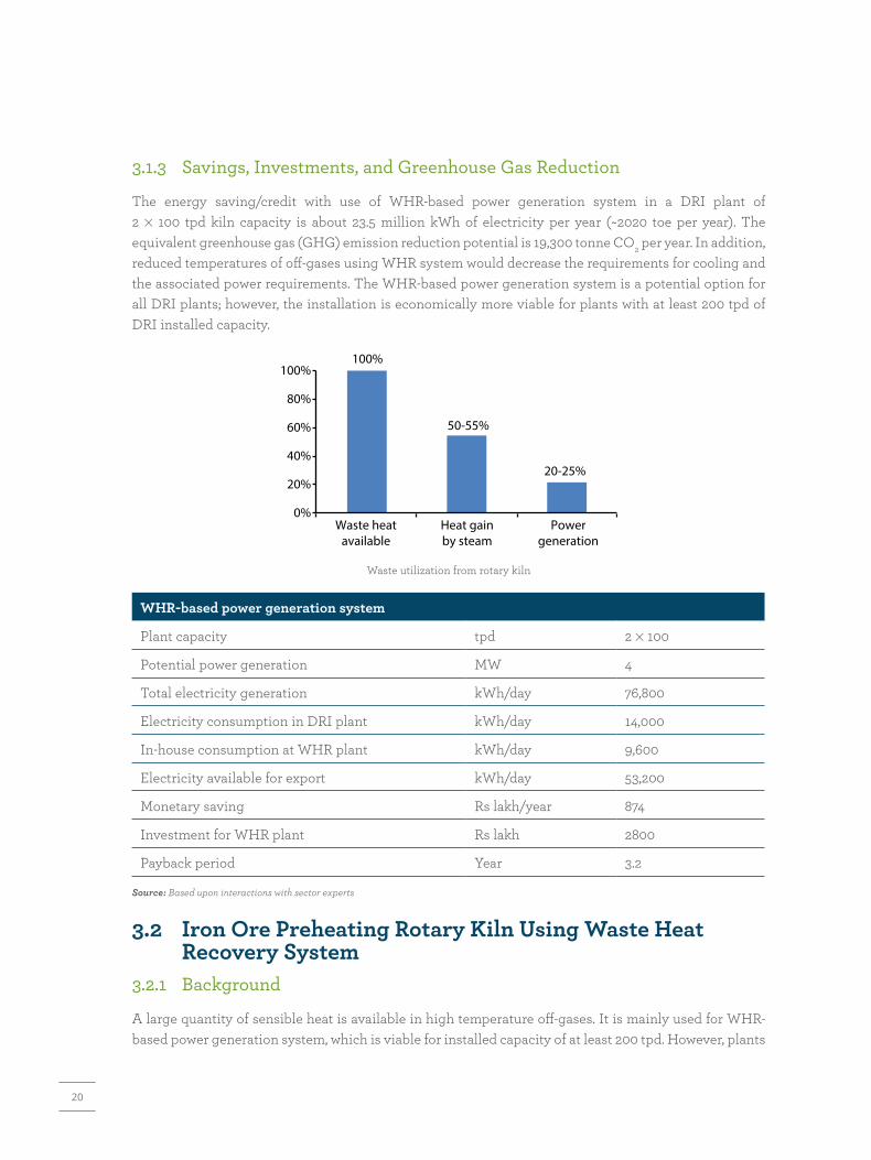
The energy saving/credit with use of WHR-based power generation system in a DRI plant of 2 × 100 tpd kiln capacity is about 23.5 million kWh of electricity per year (~2020 toe per year). The equivalent greenhouse gas (GHG) emission reduction potential is 19,300 tonne CO2 per year. In addition, reduced temperatures of off-gases using WHR system would decrease the requirements for cooling and the associated power requirements. The WHR-based power generation system is a potential option for all DRI plants; however, the installation is economically more viable for plants with at least 200 tpd of DRI installed capacity.
0%Waste heat
availableHeat gainby steam
Powergeneration
20%
40%
60% 50-55%
20-25%
80%
100%100%
Waste utilization from rotary kiln
WHR-based power generation system
Plant capacity tpd 2 × 100
Potential power generation MW 4
Total electricity generation kWh/day 76,800
Electricity consumption in DRI plant kWh/day 14,000
In-house consumption at WHR plant kWh/day 9,600
Electricity available for export kWh/day 53,200
Monetary saving Rs lakh/year 874
Investment for WHR plant Rs lakh 2800
Payback period Year 3.2
Source: Based upon interactions with sector experts
3.2 Iron Ore Preheating Rotary Kiln Using Waste Heat Recovery System3.2.1 Background
A large quantity of sensible heat is available in high temperature off-gases. It is mainly used for WHR-based power generation system, which is viable for installed capacity of at least 200 tpd. However, plants

21
of less than 200 tpd capacity generally let out off-gases without any heat recovery. In such cases, the sensible heat of off-gases can be recovered for preheating of iron ore, resulting in lower coal consumption. The reduction in coal consumption depends on recoverable amount of sensible heat and kiln efficiency.
3.2.2 Technology Brief
In a solid coal-based DRI process plant using 100 tpd kiln, about 40% of the total heat input is lost in off-gases. The sensible heat in off-gases can be used in a rotary preheater. In an iron ore preheating system, the off-gases from rotary kiln flow through rotary preheater in a counter-flow arrangement and transfer heat directly to incoming iron ore. The counter-flow- type WHR system helps in maximizing heat transfer and reduces space requirements. The preheated iron ore at about 650°C enters rotary kiln instead of being fed at ambient temperatures. Preheating of iron ore may marginally increase the generation of fines due to more handling.
WHR-based rotarypreheater
Off-gases(950°C)
Off-gasesto stack
Preheated ironore (650°C)
Iron oreinlet
Rotary kiln
Preheating rotary kiln for iron ore using WHR system
3.2.3 Savings, Investments, and Greenhouse Gas Reduction Considering a DRI plant of 100 tpd, the potential energy saving from iron ore preheating is about 15%. The annual energy saving with iron ore preheating system is 5200 tonne coal per year (2700 toe per year). The GHG emission reduction potential is 9300 tonne CO2 per year.
Other benefits associated with WHR-based iron ore preheating system include the following:
� Higher productivity since the heating zone is shifted to the preheater system and the reduction zone inside the kiln will increase.
� Reduction in energy costs.
� Reduction in power requirement for cooling and auxiliary system.
75%
80%
85%
90%
95%
100%100%
Without WHR With WHR
15%
85%
Energy saving with WHR for iron ore preheating
22
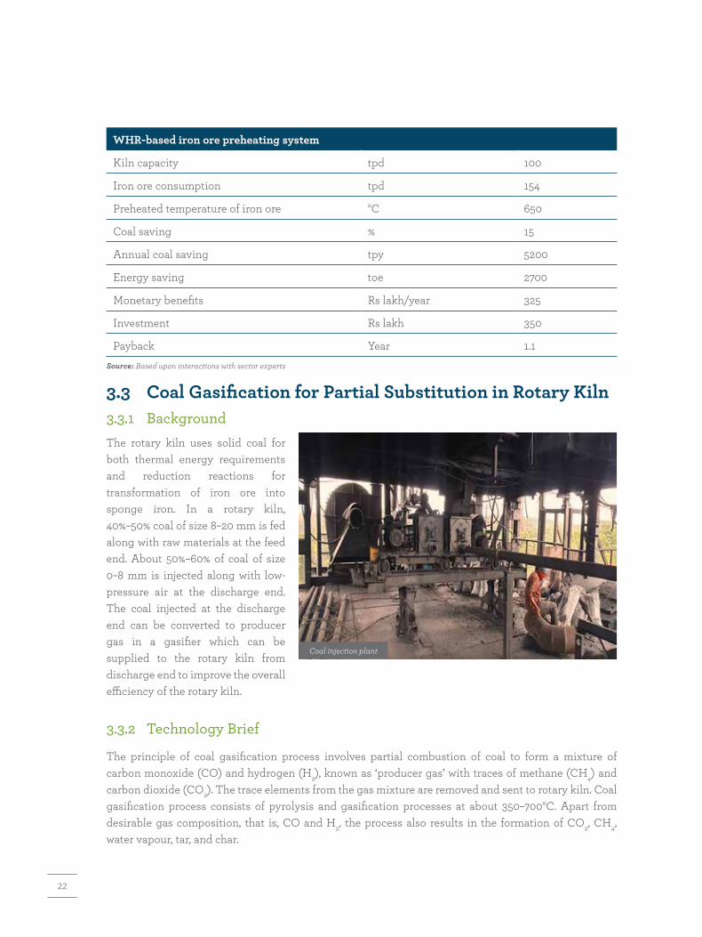
WHR-based iron ore preheating system
Kiln capacity tpd 100
Iron ore consumption tpd 154
Preheated temperature of iron ore °C 650
Coal saving % 15
Annual coal saving tpy 5200
Energy saving toe 2700
Monetary benefits Rs lakh/year 325
Investment Rs lakh 350
Payback Year 1.1Source: Based upon interactions with sector experts
3.3 Coal Gasification for Partial Substitution in Rotary Kiln3.3.1 BackgroundThe rotary kiln uses solid coal for both thermal energy requirements and reduction reactions for transformation of iron ore into sponge iron. In a rotary kiln, 40%–50% coal of size 8–20 mm is fed along with raw materials at the feed end. About 50%–60% of coal of size 0–8 mm is injected along with low-pressure air at the discharge end. The coal injected at the discharge end can be converted to producer gas in a gasifier which can be supplied to the rotary kiln from discharge end to improve the overall efficiency of the rotary kiln.
3.3.2 Technology Brief
The principle of coal gasification process involves partial combustion of coal to form a mixture of carbon monoxide (CO) and hydrogen (H2), known as ‘producer gas’ with traces of methane (CH4) and carbon dioxide (CO2). The trace elements from the gas mixture are removed and sent to rotary kiln. Coal gasification process consists of pyrolysis and gasification processes at about 350–700°C. Apart from desirable gas composition, that is, CO and H2, the process also results in the formation of CO2, CH4, water vapour, tar, and char.
Coal injection plant

23
Producergas
(CO + H2)Cleaningsystem
Slag
Coal/waterslurry
Rotary kiln
Coal gasification system for rotary kiln in sponge iron production
The gasification process is mainly endothermic involving the following reactions:
C + O2 = CO2 – 94.05 kcal/mol
2H2 + O2 = 2H2O – 68.3 kcal/mol
The gasifier system comprises a vertical chamber wherein coal–water slurry is fed from the top and air supply is met through a blower. The producer gas is passed through either cyclone separator or wet scrubber to clean the gases. The coal gasifier system is provided with programmable logic controller (PLC) control system for automatic monitoring and control of producer gas generation.
3.3.3 Savings, Investments, and Greenhouse Gas Reduction
The energy saving with partial substitution of solid coal used in rotary kiln of 100 tpd capacity with producer gas from coal gasification process is about 20%. The annual energy saving with coal gasification system is 4200 tonne coal per year, which is equivalent to a monetary savings of approximately Rs 260 lakh per year. However, the plant will have to invest for setting up of a producer gas system of corresponding capacity. The GHG emission reduction potential is 7500 tonne CO2 per year.
3.4 Waste Heat Recovery- based Absorption Chiller3.4.1 Background
Direct reduction of iron plants require comfort cooling in control rooms and administrative buildings. The cooling load is met primarily through stand-alone air-conditioning system. One of the potential
Benefits of using coal gasifier
Apart from energy savings, the other benefits due to replacement of coal-fine injection with producer gas at the discharge end include:
(1) Close control over kiln operating parameters and hence smooth operation
(2) Increased kiln capacity by 20%
(3) Increased campaign
(4) Increased metallization and hence better recovery of metal

24
options is to use a fraction of the sensible heat available in off-gases in a WHR-based system, that is vapour absorption machine (VAM) to replace existing cooling arrangements. The WHR-based VAM system can be installed in all DRI plants irrespective of existing WHR systems such as WHR-based power generation or WHR-based iron ore preheater.
3.4.2 Technology Brief
The compact stand-alone air-conditioning systems can be replaced with energy-efficient VAM system. A VAM system primarily replaces conventional compression system, which is energy intensive. It uses a generator-cum-absorber system to ensure circulation of refrigerant. Lithium bromide water solution is generally used in VAM systems.
In a DRI plant, a small quantity of off-gases from rotary kiln is required to operate VAM system, which eliminates electricity requirements for operating compressor system except for operating a low-capacity pump. The absorption chillers can be customized to suit wide range of capacities with single, double, or triple effect.
VAM
Enduse-1
Fan
Exhaust gases
AHU
Mixed airFresh air
To return duct
Off-gas
Cool air
Enduse-2
Rotary kiln
VAM-based absorption chiller
3.4.3 Investments, Energy Saving, and Greenhouse Gas Reduction
A WHR-based VAM system can be customized to meet chilling loads with negligible energy consumption. Practically, energy saving that can be achieved by replacing conventional chillers with a VAM-based system of 10 TR capacity to cater to the requirements of instrumentation and control room is estimated to be 42,000 kWh per year (4 toe per year). The GHG emission reduction potential with use of proposed VAM is 34 tonne CO2 per year.
25
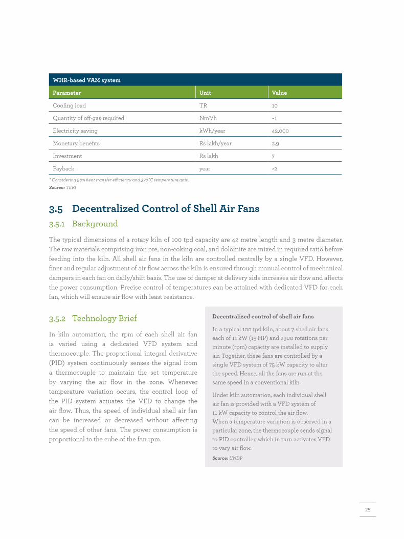
WHR-based VAM system
Parameter Unit Value
Cooling load TR 10
Quantity of off-gas required* Nm3/h ~1
Electricity saving kWh/year 42,000
Monetary benefits Rs lakh/year 2.9
Investment Rs lakh 7
Payback year >2
* Considering 90% heat transfer efficiency and 370°C temperature gain.Source: TERI
3.5 Decentralized Control of Shell Air Fans3.5.1 Background
The typical dimensions of a rotary kiln of 100 tpd capacity are 42 metre length and 3 metre diameter. The raw materials comprising iron ore, non-coking coal, and dolomite are mixed in required ratio before feeding into the kiln. All shell air fans in the kiln are controlled centrally by a single VFD. However, finer and regular adjustment of air flow across the kiln is ensured through manual control of mechanical dampers in each fan on daily/shift basis. The use of damper at delivery side increases air flow and affects the power consumption. Precise control of temperatures can be attained with dedicated VFD for each fan, which will ensure air flow with least resistance.
3.5.2 Technology Brief
In kiln automation, the rpm of each shell air fan is varied using a dedicated VFD system and thermocouple. The proportional integral derivative (PID) system continuously senses the signal from a thermocouple to maintain the set temperature by varying the air flow in the zone. Whenever temperature variation occurs, the control loop of the PID system actuates the VFD to change the air flow. Thus, the speed of individual shell air fan can be increased or decreased without affecting the speed of other fans. The power consumption is proportional to the cube of the fan rpm.
Decentralized control of shell air fans
In a typical 100 tpd kiln, about 7 shell air fans each of 11 kW (15 HP) and 2900 rotations per minute (rpm) capacity are installed to supply air. Together, these fans are controlled by a single VFD system of 75 kW capacity to alter the speed. Hence, all the fans are run at the same speed in a conventional kiln.
Under kiln automation, each individual shell air fan is provided with a VFD system of 11 kW capacity to control the air flow. When a temperature variation is observed in a particular zone, the thermocouple sends signal to PID controller, which in turn activates VFD to vary air flow.Source: UNDP

26
ThermocoupleRotary kiln
Shellair fans
VFD
ThermocoupleRotary kiln
Shellair fans
VFD
Decentralized VFD system in rotary kiln Source: UNDP, India
3.5.3 Investments, Energy Saving, and Greenhouse Gas Reduction
The annual energy saving with installation of decentralized VFD systems for shell air fans for 100 tpd capacity rotary kiln is 19,000 kWh per year (1.6 toe per year). The GHG emission reduction potential is 16 tonne CO2 per year.
Automation and control system in rotary kiln
Energy saving toe/year 1.6
Monetary benefits* Rs lakh/year 0.5
Investment Rs lakh 2.8
Payback Year 5.2
* Monetary savings estimated using cost of export powerSource: TERI’s analysis
The main advantage with the use of decentralized VFDs is that it eliminates the manual intervention in controlling air flow across the kiln, leading to close control over temperature in each zone. It is worth mentioning that the payback period of a decentralized system will be much lower, considering the other benefits and electricity costs from grid source.
3.6 Mullite-based Kiln Lining3.6.1 Background
In conventional rotary kiln, high-alumina low-cement castable refractories are used as inner lining to withstand a temperature of close to 1050°C. The thermal conductivity of high-alumina refractories is quite high, of about 2.7 W/m-K, which leads to higher radiation or surface heat loss in the kiln. The temperatures of external surfaces of the kiln are about 180–250°C in reduction zone and 150–180°C in discharge end. The radiation heat loss of the rotary kiln typically accounts for about 5% of the total heat input, which can be reduced with application of low-thermal conductivity material such as mullite-based kiln lining.

27
3.6.2 Technology Brief
The high-alumina low-cement castable refractory material can be replaced with mullite-based high-alumina castable refractory of thermal conductivity of 1.7 W/m-K. Two of the many advantages associated with mullite-based refractories are: (i) excellent high- temperature strength and (ii) high resistance to thermal shock, oxidation, and abrasion. With use of mullite-based high-alumina castables, the outer shell temperature of the rotary kiln gets reduced by 50–80°C, thereby reducing heat loss through kiln shell by at least 30%.
3.6.3 Savings, Investments, and Greenhouse Gas Reduction
The annual energy saving with mullite-based lining of rotary kiln of 100 tpd capacity is 580 tonne coal per year (300 toe per year). The GHG emission reduction potential is 1050 tonne CO2 per year.
Every 10°C increase in surface temperature increases the radiation loss from the exposed surfaces by 6%–7%.
Mullite-based kiln lining
Reduction in radiation losses % 30
Energy saving toe/year 300
Monetary benefits Rs lakh/year 36
Investment Rs lakh 50
Payback Year 4.1
Source: UNDP
3.7 Switch Over to Iron Ore Pellets3.7.1 BackgroundThe coal-based DRI plants use iron ore lumps of size 5–20 mm, which are commonly known as calibrated lump ore (CLO). The mined iron ore available to DRI plants has generally low-iron content. Further, the processing of lumps results in formation of fines and requires agglomeration to maintain the yield. Iron ore pellets can be used in place of lumps to increase the yield.
Use of iron ore pellets in DRI production
The iron ore used in coal-based rotary kilns is in the form of sized lumps or pellets. These can be either procured or processed in-house. The in-house processing of large lumps generates fines, resulting in iron ore losses. Switch over to pellets offers the following advantages:
� Minimizes raw material preparation facility � No loss on ignition, resulting in better yield � Uniform metallization � Less fine generation, leading to lower accretion and
reduced load on bag filters � Reduces slag quantity and related handling � Improves yield � Eliminates the use of magnetic separators � About 20% more throughput per unit of rotary kiln volume
� Reduce thermal load for direct reductionSource: UNDP

28
3.7.2 Technology BriefPelletizing is an agglomerating process of converting iron ore fines into uniform-sized material which can be charged directly into the rotary kiln for DRI production. Iron pellets are prepared by mixing iron ore fines having a size of less than 200 mesh (0.074 mm) with additives like bentonite and shaping into oval or spherical balls with size in the range of 8–16 mm diameter in a pelletizer. The iron pellets are further hardened by firing separately. The use of uniform size and shaped pellets as against the non-uniform and varying size of lumps as charge material results in improved performance of the kiln. The use of iron ore pellets reduces loss on ignition. Two of the different iron ore pelletization processes are (i) straight travelling grate process and (ii) grate kiln process.
3.7.3 Investments, Energy Saving, and Greenhouse Gas ReductionThe energy-saving potential with use of iron ore pellets in place of iron ore lumps is 15%. The annual energy saving for a DRI plant of 100 tpd capacity is 2730 toe per year. The total monetary benefit that can be accrued with the use of iron ore pellets is estimated to be Rs 326 lakh. The GHG emission reduction potential is 9400 tonne CO2 per year.
3.8 Artificial Neural Network for Accretion Control3.8.1 BackgroundAccretion in rotary kiln refers to deposition or build-up of low-melting oxide compounds on the internal surface in reduction zone. This leads to decrease in fusion temperature of the charge material which adheres to the kiln surfaces. Accretion results in formation of slag layer, which affects the metalizing reactions. The accretion forms ring structure inside the kiln due to rotation and the thickness increases over a period of time. Continuous deposits lead to increase in thickness, resulting in reduced working volumes and forces unscheduled kiln shutdown as those cannot be removed in-place during operation. The optimum performance of DRI plant would require addressing of operating parameters such as accretion control, product quality, and kiln availability. Optimization of these parameters would help in reducing accretion, increasing product quality, and enhancing kiln availability, thereby improving the energy performance of rotary kilns.
3.8.2 Technology BriefAccretion formation largely depends on quality of feed material such as gangue content iron ore, ash in coal, and operating temperatures. It can be minimized by adopting the following measures:
(i) Using iron ore with low-gangue content, high-tumbler index, and low-aberration index.
(ii) Using non-coking coal with low-ash content, high reactivity, high-ash fusion temperature, and low swelling and caking index.
Iron ore pellets

29
(iii) Maintaining temperature profile below the sintering temperature along the entire kiln length.
(iv) Using suitable alloy additives to increase the fusion temperature, and coatings on refractory wall to withstand high temperature and aberration.
A dynamic operation model using artificial neural network (ANN) can be effectively used for controlling accretion in kilns, improving product quality, and enhancing kiln availability. The key parameters and their interrelations are used to control accretion and product quality. A close monitoring and control of rotary kiln temperatures in different zones is of paramount importance for controlling accretion in rotary kilns. The neural network predicts temperatures in different zones based on parameters such as fixed carbon content in coal, kiln pressure and multilayered damper (MLD) position of ID fans using regression analysis which in turn is used to control accretion in the kiln. The ANN can be further used to control quality of the product, which uses parameters such as fixed carbon in coal, kiln RPM, and air flow through fans.
3.8.3 Energy Saving and Greenhouse Gas ReductionThe major benefits of using ANN include (i) reduced fluctuations of kiln inlet and outlet pressure, (ii) auto operation of MLD of ID fan, (iii) reduced shutdowns and significant gain in operating days, and (iv) about 5%–7% increase in production. All these benefits will lead to reduction in overall SEC level and GHG emission over kiln’s life cycle.
3.9 Moisture Reduction from Coal3.9.1 BackgroundThe coal-based DRI plants in India use either domestic coal or imported coal, depending on landed costs and quality. Generally, the moisture content in coal is in the range of 8%–12%, depending on ambient conditions. The moisture content is reduced to 4%–5% before feeding into the kiln. Open sun drying is practised to reduce surface moisture. Reduction or minimization of surface moisture present in coal would help in bringing down heat losses due to moisture content in coal and effectively reduces the overall coal consumption.
3.9.2 Technology BriefOther than sun drying, the DRI plants can also use rotary drum dryer for moisture removal. The rotary drum dryer is a direct-type heat exchanger in which preheated air and green coal are fed. The green coal is fed in the opposite direction which picks up heat from hot air at about 250–300°C and the surface moisture is optimally removed in the dryer. Hot air is generated by picking up heat from off-gases through separate heat exchanger. This arrangement would eliminate potential fire hazards of using directly off-gases over low-moisture coal. The dry coal can be directly fed to rotary kiln and eliminate heat losses due to surface moisture in coal. The WHR-based rotary drum dryer can be installed in all existing DRI plants irrespective of the installed capacities and having other WHR-based applications.
Recycling of in-house wastes
(i) Waste char used in DRI plants is generally used as fuel in WHR boilers. However, smaller capacity plants may recycle waste char along with prime coal to reduce energy consumption.
(ii) Coal fine wastes can be briquetted and recycled through feed end. This could result in a coal saving of 8%–10%.

30
3.9.3 Savings, Investments, and Greenhouse Gas Reduction
The energy-saving potential with rotary drum dryer for a 100-tpd kiln using DRI process is about 3%. The coal saving from rotary dryer is estimated to be 1065 tpy (554 toe per year). The GHG emission reduction potential is 1900 tonne CO2 per year.
WHR-based rotary drum dryer for surface moisture removal for coal
Off-gases
Off-gasesto stack
Dry coalwith reduced
moisturePreheated air
Preheated air
Coal(High surface
moisture)
Rotary kiln
WHR-based rotary drum dryer for surface moisture removal from coal
Temperature of off-gases °C 550
Quantity of off-gas required* Nm3/h 15
Temperature of preheated air °C 250
Initial surface moisture in coal % 10±2
Final surface moisture in coal % 4
Energy saving % 3.5
Coal saving tpy 1275
Monetary benefits Rs lakh/year 66
Investment Rs lakh 100
Payback Year 1.5
* Considering overall system efficiency of 40%; marginal increase in energy consumption due to blower and drum operation. Source: TERI
3.10 Energy-efficient Motors3.10.1 Background
The share of electricity consumption in DRI production process is very low compared to thermal energy consumption; however, its share is quite significant in terms of absolute value. The motive loads are the major consumers of electricity, which includes equipment like kiln drive, ID fan, shell air fans, crushers, cooling tower pumps, material handling system, and air compressor. For a 100-tpd coal-based DRI plant, the motor capacity is in the range of 7.5 kW to 75 kW. Most of the motors used are of standard type.

31
3.10.2 Technology Brief
High-efficient motors consume less power, both at part load and at full-load conditions and, hence, the inefficient motors can be replaced with premium efficiency IE3 motors. There is a difference of 2%–4% for energy-efficiency improvements with the use of IE3 motors, depending on motor capacities. The quantum of energy savings is much higher for rewound motors.
Comparison of energy efficiency of motors
Motor rating (kW)Efficiency (%)
2-pole 4-pole 6-pole
Standard Energy efficiency
Standard Energy efficiency
Standard Energy efficiency
7.5 86.0 90.1 86.0 90.4 84.7 89.1
15 88.7 91.9 88.7 92.1 88.7 91.2
30 90.7 93.3 90.7 93.6 90.2 92.9
45 91.7 94.0 91.7 94.2 91.4 93.7
75 92.7 94.7 92.7 95.0 92.6 94.6
90 93.0 95.0 93.0 95.2 92.9 94.9
Source: IS 12615:2011 (three-phase, 50 Hz, single speed and squirrel cage induction motors)
3.10.3 Savings, Investments, and Greenhouse Gas Reduction
A typical example of electrical motor application is ID fan in rotary kiln, which uses 75 kW standard motor in a 100-tpd plant. This standard motor can be replaced with an IE3 (4-pole) motor, having efficiency of 95%. Increase in the efficiency is possible, depending upon base case. The annual energy saving with use of IE3 motor in ID fan is 22,100 kWh per year (2 toe per year). The GHG emission reduction potential with use of IE3 motor is 18 tonne CO2 per year.
IE3 motors for crushers
Parameter Unit Existing IE3
Motor capacity kW 75 75
Efficiency % 90 95
Energy saving kWh/year 22,100
Monetary benefits* Rs lakh/year 0.63
Investment Rs lakh 3.0
Payback Year 4.7
* Based on cost of export power to grid. Source: TERI analysis

32
3.11 Energy-efficient Pumps3.11.1 Background
Cooling water is used in rotary cooler for reducing the temperature of the DRI product from 950°C to 120°C to avoid oxidation of sponge iron. Water is sprayed over the outer surface to reduce the temperature of the material indirectly. The efficiency of the pumps used in cooling water circuit are generally low, at about 50%. The use of energy-efficient pumps would lead to reduced energy consumption by pumping system.
3.11.2 Technology Brief
An efficient pumping system depends on factors such as water flow rate, piping layout, control techniques, and pump selection. Energy-efficient centrifugal pumps can be used in place of inefficient pumps, which provide advantages such as high-flow rates, smooth and non-pulsating delivery, and regulation of flow rate over a wide range. Centrifugal pumps are compact and can be easily disassembled for maintenance purposes. The wear caused by normal operation is minimal in the case of centrifugal pump due to less number of moving parts.
25
0 200 400 600 800
NPSH REQ
1000 120015
20
25
30
50
75
100
125
150
175
200
NPSHR
FEET
Tota
l hea
dfee
t
Max HP for6.88 Dia impellerRPM3500
6.88
6.50
6.18
5.88
5.50
40 50 60 70
70
75
75
80
80
83
83
85
85
30HP
HP
HP
HP
HP40
25
15
20
3000250020001500
30.019.010.85.72.4
Max HP
GPM
Characteristic curve for a pump
The performance curve of a pump is an important consideration for selection of an energy-efficient pump. A pump can be operated efficiently by keeping its operation close to the best efficiency point (BEP), while meeting the requirements such as flow rate and head required. To minimize energy consumption, the pump should be selected in such a manner that the system curve intersects the pump curve within 20% of its BEP. In order to maximize the efficiency, the pump impeller should be selected in the mid-operating range.

33
3.11.3 Savings, Investments, and Greenhouse Gas Reduction
As an example, the inefficient pump of the cooling tower can be replaced with an energy-efficient pump while keeping similar hydraulic power output. The motor rating of an energy-efficient system will be 18.5 kW, replacing 30-kW inefficient pump. The energy saving is estimated to be 84,100 kWh per year (7.2 toe per year). The investment requirement is about Rs 1.3 lakh with a payback period of about 0.5 year. The GHG emission reduction potential is 69 tonne CO2 per year.
Energy-efficient pumps for rotary cooler
Parameter Unit Existing EE pump
Flow rate m3/h 300 300
Head M 15 15
Pump efficiency % 50 70
Motor efficiency % 85 93
Electricity saving kWh/year 84,100
Monetary benefits Rs lakh/year 2.4
Investment Rs lakh 2.0
Payback Year <1
* Based on cost of export power to grid.Source: TERI analysis
3.13 Variable Frequency Drives for Air Compressors3.13.1 Background
In DRI plants, compressed air is used both in process and in service requirements. Compressors execute load–unload mode or on-off line control of operation. In load–unload compressor, motor keeps running continuously but unloads the compressor at set discharge pressure. The power consumption of air compressor during unload varies about 30%–40% of rated power consumption for rotary screw compressor (without VFD) and 15%–20% for reciprocating-type air compressor.
3.13.2 Technology Brief
The VFD is used to minimize electricity consumption during unload in rotary screw compressor. VFD-enabled air compressors can deliver variable air flow to maintain set pressure based on end-use points. The energy consumption and air flow of a VFD-based air compressor is directly proportional to motor speed and, hence, results in higher energy savings as compared to fixed-speed compressors with partial loading. The VFD control adjusts the speed of drive motor and coupled compressor to respond to changes in air demand while maintaining constant pressure. In a multi-air compressor system, fixed-air compressors are used to meet the base load, while VFD-based air compressor is used to supply the fluctuating or trim load.

34
3.13.3 Savings, Investments, and Greenhouse Gas Reduction
The annual energy saving with use of VFD-based rotary air compressor in DRI plant is 70,000 kWh per year (6 toe per year). The GHG emission reduction potential is 63 tonne CO2 per year.
VFD application in air compressor
Parameter Unit Inefficient compressor VFD-built compressor
Rated capacity CFM 126 63–142
Rated power kW 22 22
Full load time h/year 4,320 3,110
Annual energy consumption kWh/year 145,700 75,200
Monetary benefits Rs lakh/year 2.3
Investment Rs lakh 3.0
Payback Year 1.3* Based on cost of export power to grid Source: TERI analysis
3.14 Fibre-reinforced Plastic Blades for Cooling Tower Fans3.14.1 Background
Water is sprayed on the top of rotary cooler to cool down the products indirectly. Metal blades—made of aluminium—are generally used in a large number of cooling tower fans. It is important to note that, the use of metal blades substantially increases the overall weight of the cooling system, leading to higher power consumption.
3.14.2 Technology Brief
The metal blades in cooling tower fan can be replaced with lighter fibre-reinforced plastic (FRP) blades, which would reduce the power consumption of the cooling tower system. Further, it increases the possibility of de-rating or resizing the motor capacity of cooling tower fan to allow the use of lower-sized motor. The other advantages of FRP blade include high reliability and better performance due to lower failure rate.
FRP blades
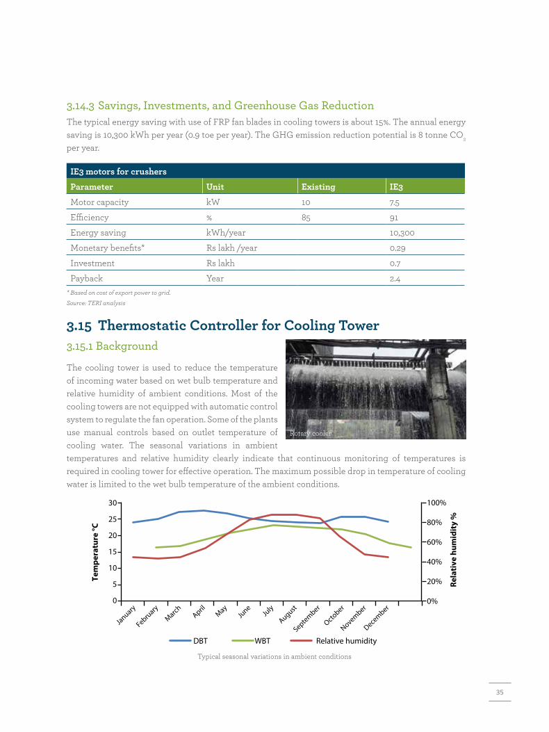
35
3.14.3 Savings, Investments, and Greenhouse Gas ReductionThe typical energy saving with use of FRP fan blades in cooling towers is about 15%. The annual energy saving is 10,300 kWh per year (0.9 toe per year). The GHG emission reduction potential is 8 tonne CO2 per year.
IE3 motors for crushers
Parameter Unit Existing IE3
Motor capacity kW 10 7.5
Efficiency % 85 91
Energy saving kWh/year 10,300
Monetary benefits* Rs lakh /year 0.29
Investment Rs lakh 0.7
Payback Year 2.4* Based on cost of export power to grid.Source: TERI analysis
3.15 Thermostatic Controller for Cooling Tower3.15.1 Background
The cooling tower is used to reduce the temperature of incoming water based on wet bulb temperature and relative humidity of ambient conditions. Most of the cooling towers are not equipped with automatic control system to regulate the fan operation. Some of the plants use manual controls based on outlet temperature of cooling water. The seasonal variations in ambient temperatures and relative humidity clearly indicate that continuous monitoring of temperatures is required in cooling tower for effective operation. The maximum possible drop in temperature of cooling water is limited to the wet bulb temperature of the ambient conditions.
Rotary cooler
0%
DBT
0
5
10
15
20
25
30
20%
40%
Rela
tive
hum
idit
y %
Tem
pera
ture
°C
60%
80%
100%
January
February
March AprilMay
June
July
August
September
October
November
December
WBT Relative humidity
Typical seasonal variations in ambient conditions

36
3.15.2 Technology Brief
Automatic control system is preferred in place of manual controls. The most common system used in cooling towers is thermostatic controller which senses the outlet temperature of the cooling water. The controller switches on or off the fan automatically based on prevailing level of cooling water temperature.
3.15.3 Savings, Investments, and Greenhouse Gas ReductionThe typical energy saving with installation of thermostatic controllers in cooling water circuit is about 20%, depending on geographical location due to variations in winter season. The annual energy saving is 13,800 kWh per year (1.2 toe per year). The GHG emission reduction potential is 11 tonne CO2 per year.
Thermostatic controller in cooling tower
Parameter Unit Value
Motor capacity kW 10
Energy saving% 20%
kWh/year 13,800
Monetary benefits* Rs lakh /year 0.4
Investment Rs lakh 0.15
Payback Year 0.5
* Based on cost of export power to grid. Source: TERI analysis
3.16 Automatic Power Factor ControllerThe electrical loads associated with rotary kiln-based DRI plant mainly include ID fan, kiln drive, shell air fan, bag filter system, raw material crusher, water pump, air compressor. The overall power factor of the plant is associated with electrical billing. Lower power factor will attract penalties, whereas maintaining higher power factor will earn rebate on the billed amount. It is essential for the plant to regularly inspect the power factor and take remedial actions, if necessary. The power factor can be improved and kept close to unity by installing automatic power factor controller (APFC) at incomers and high-load centres.
Power factor at load centres
Load centre Preferable power factor
Induction motor 0.95
Distribution system 0.99
Welding machine 0.90 and above
DC drive 0.90 and above
Fluorescent lamp 0.95 and above
37
POTENTIAL LOW-CARBON TECHNOLOGY OPTIONS FOR INDIAN DIRECT REDUCTION OF IRON SECTOR
4

38
One of the best options to improve the energy efficiency and reduce greenhouse gas (GHG) emissions from Indian DRI sector is to switch over to gas-based route in future and work towards making gas-based route commercially viable. Another option that Indian DRI plants can explore is to adopt efficient coal-based technologies that are being used for DRI production globally.
Coal-based DRI processes
Process Raw material Product Largest single module (Mtpa)
ACCAR/grate car Fines Solid 0.35
AISI/cyclone Fines Molten 0.5
AISI/pellet Pellets Molten 0.35
Circofer Fines Solid 0.5
COREX Pellets/lumps Molten 1.2
DIOS Fines Molten 1.0
DRC Pellets/lumps Solid 0.15
FASTMET Fines Solid 0.45
FINEX Fines Solid 0.25
HIsmelt Fines Molten 0.50
INMETCO Fines Solid 0.3
Romelt Fines/lumps Molten 0.4
SL/RN Pellet/lump/fines Solid 0.25
Tecnored Fines Molten 0.3
Coal gasification + HYL self-reforming (ZR) plant
Pellets/lumps Molten -
Coal-based ULCORED - Solid -
Sources: Duarte (n.d.); Sikstrom (2013)
A brief highlight of the select technological options that are best suited for DRI production in India is provided in this section. The options have been categorized into three sub-sections. Section 4.1 covers the technologies using direct coal; Section 4.2 details out the technologies using coal gasification route; and technologies using gas route (natural gas and hydrogen) are covered in Section 4.3. In addition, a separate section highlights the usage of hydrogen for Indian iron and steel sector (Section 4.4).
The Indian direct reduction of iron (DRI) sector is unique as coal-based route is generally employed unlike globally accepted gas-based options. The wide use of coal-based route in India is mainly attributed to the availability of large quantity of non-coking coal. In comparison to gas-based processes, the coal-based DRI production process is quite energy intensive and poses environment-related issues. Being a developing country with steel demand projected to reach between 500 and 760 million tonne (Mt) by 2050, the country needs to adopt energy-efficient and environment-friendly steel production technologies to meet the growing steel demand.
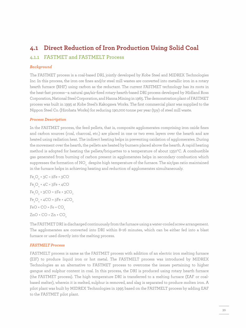
39
4.1 Direct Reduction of Iron Production Using Solid Coal4.1.1 FASTMET and FASTMELT Process
Background
The FASTMET process is a coal-based DRI, jointly developed by Kobe Steel and MIDREX Technologies Inc. In this process, the iron ore fines and/or steel mill wastes are converted into metallic iron in a rotary hearth furnace (RHF) using carbon as the reductant. The current FASTMET technology has its roots in the heat-fast process—a natural gas/air-fired rotary-hearth-based DRI process developed by Midland Ross Corporation, National Steel Corporation, and Hanna Mining in 1965. The demonstration plant of FASTMET process was built in 1995 at Kobe Steel’s Kakogawa Works. The first commercial plant was supplied to the Nippon Steel Co. (Hirohata Works) for reducing 190,000 tonne per year (tpy) of steel mill waste.
Process Description
In the FASTMET process, the feed pellets, that is, composite agglomerates comprising iron oxide fines and carbon sources (coal, charcoal, etc.) are placed in one or two even layers over the hearth and are heated using radiation heat. The indirect heating helps in preventing oxidation of agglomerates. During the movement over the hearth, the pellets are heated by burners placed above the hearth. A rapid heating method is adopted for heating the pellets/briquettes to a temperature of about 1350°C. A combustible gas generated from burning of carbon present in agglomerates helps in secondary combustion which suppresses the formation of NOx despite high temperature of the furnace. The air/gas ratio maintained in the furnace helps in achieving heating and reduction of agglomerates simultaneously.
Fe2O3 + 3C = 2Fe + 3CO
Fe3O4 + 4C = 3Fe + 4CO
Fe2O3 + 3CO = 2Fe + 3CO2
Fe3O4 + 4CO = 3Fe + 4CO2
FeO + CO = Fe + CO2
ZnO + CO = Zn + CO2
The FASTMET DRI is discharged continuously from the furnace using a water-cooled screw arrangement. The agglomerates are converted into DRI within 8–16 minutes, which can be either fed into a blast furnace or used directly into the melting process.
FASTMELT Process
FASTMELT process is same as the FASTMET process with addition of an electric iron melting furnace (EIF) to produce liquid iron or hot metal. The FASTMELT process was introduced by MIDREX Technologies as an alternative to FASTMET process to overcome the issues pertaining to higher gangue and sulphur content in coal. In this process, the DRI is produced using rotary hearth furnace (the FASTMET process). The high temperature DRI is transferred to a melting furnace (EAF or coal-based melter), wherein it is melted, sulphur is removed, and slag is separated to produce molten iron. A pilot plant was built by MIDREX Technologies in 1995 based on the FASTMELT process by adding EAF to the FASTMET pilot plant.

40
FASTMELT processSource: Kobelco
DRI
DRImelter
Scrubber Gas holder
Stack
ID fan
Bag�lter
Briquettemachine
Pelletizer
Pellet dryerRHF
O�-gas Fuel gas
Melting
Reduction
Agglomeration
Wasteheat boiler
O�-gas
Mixer
Raw materialbins
Air preheater
Steam forpower plant
or
Resource consumption in FASTMET process
Description Unit Specific consumption
Iron ore fines tonne 1.2–1.35
Coal tonne 0.3–0.4
NG GJ 2.1–2.9
Electricity kWh 80–100
Bentonite tonne 0.030–0.040
Nitrogen Nm3 2.5
Water m3 1–2
Source: Kekkonen and Holappa (2000)
The average SEC of FASTMET process is 1.86 Gcal/t-DRI (ranging from 1.59 to 2.14 Gcal/t-DRI). Coal accounts for about two-thirds of the total energy consumption in the process. The average GHG emissions with FASTMET process is 0.72 tCO2/t-DRI.
Technology Status
The installed capacity of FASTMET technology-based DRI plants varies in 16,000–190,000 tpa range.

41
Coal (64%)
Natural gas (32%)
Electricity (4%)
Status of technology
Plant Location Year of commissioning Capacity (tpa)
Nippon Steel Hirohata, Japan 2000 190,000
Kobe Steel Kakogawa, Japan 2004 16,000
Nippon Steel Hirohata, Japan 2005 190,000
Source: Ishikawa, Kopfle, Mcclelland, et.al. (2008)
Energy share in FASTMELT process
4.1.2 ITmk3
Background
ITmk3 (Ironmaking Technology Mark 3) is a rapid iron-making process that uses iron ore fines and coal fines. With reference to generation classes of iron-making processes, ITmk3 is third-generation iron-making process. The blast furnace (BF) and the direct reduction iron making (DRI) are typified by the MIDREX process as the first- and second-generation processes, respectively. The development of this process was started by Kobe steel in 1996. Later on the collaborative research involving universities and institutes (Tohoku University, Tokyo Institute of Technology, University of Surrey (UK), and Max Planck Institute in Germany) resulted in further refinement and development of the process. The first commercial plant using ITmk3 technology is Steel Dynamics, Inc., USA started the production in 2010.
Process Description
In this process, iron ore concentrate and non-coking coal (reducing agent), limestone (flux), and bentonite (binder) are mixed together and agglomerated into green self-reducing pellets. These pellets are fed into a rotary hearth furnace (RHF) where self-reducing, fluxing dried green balls are reduced, carburized, and smelted. The product is granular iron called iron nuggets (96%–97% pure). Iron nuggets improve the productivity and energy efficiency of electric arc furnaces (EAFs). With better melt-ability than blast-furnace pig iron, iron nuggets can be continuously fed into EAFs.
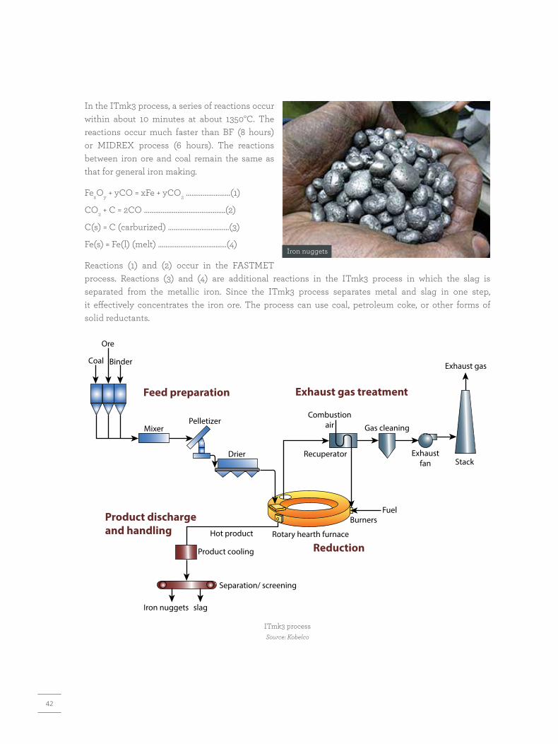
42
In the ITmk3 process, a series of reactions occur within about 10 minutes at about 1350°C. The reactions occur much faster than BF (8 hours) or MIDREX process (6 hours). The reactions between iron ore and coal remain the same as that for general iron making.
FexOy + yCO = xFe + yCO2 ……………………(1)
CO2 + C = 2CO ……………………………………..(2)
C(s) = C (carburized) ……………………………(3)
Fe(s) = Fe(l) (melt) ………………………….……(4)
Reactions (1) and (2) occur in the FASTMET process. Reactions (3) and (4) are additional reactions in the ITmk3 process in which the slag is separated from the metallic iron. Since the ITmk3 process separates metal and slag in one step, it effectively concentrates the iron ore. The process can use coal, petroleum coke, or other forms of solid reductants.
Ore
Coal Binder
MixerPelletizer
Drier
Hot product Rotary hearth furnace
Product cooling
Iron nuggets slag
Separation/ screening
Combustionair Gas cleaning
Exhaust gas
StackRecuperator Exhaust
fan
FuelBurners
Feed preparation Exhaust gas treatment
Product dischargeand handling
Reduction
ITmk3 processSource: Kobelco
Iron nuggets

43
Resource Consumption
ITmk3 process consumes about 30% less energy and the GHG emissions are about 20% lower as compared to BFs.
Specific consumption of input materials
Input Specific consumption (per tonne iron nuggets)
Iron ore fine 1.5 tonne (> 60% Fe)
Non-coking coal 0.5 tonne
Fuel gas 4.6 GJ
Electricity 200 kWh
Water 2 m3
Air 85 m3
Nitrogen 12 m3
Source: Kar (2015)
Technology Status
Itmk3 technology is commercially available. The installed capacity of first commercial plant, which is a joint venture of Kobe Steel and SDI, was 500,000 tpa.
Status of technology
Plant Location Year of commissioning Capacity (tpa)
Mesabi Nugget Delaware, LLC Hoyt Lake, Minnesota, USA
2010 500,000
Source: Kobelco
4.2 Direct Reduction of Iron Production Using Coal Gasification4.2.1 MIDREX Process (MxCol Process)
MxCol® is the trademark for use of syngas derived from coal in the commercially proven MIDREX® direct reduction process. MIDREX has collaborated with Siemens VAI Metals Technologies GmbH, Paul Wurth SA., Lurgi GmbH, Synthesis Energy Systems, Inc. and Praxair, Inc. to develop innovative solutions towards generation and use of reducing gas for direct reduction process.
Process Description
In this process, the MIDREX reactor and its auxiliary systems are the same as for gas-based MIDREX plants. The reactor includes dynamic top and bottom seals and operates at a relatively low pressure of 1.5 bar. The oxide material flows downwards by gravity through reduction, transition, and cooling

44
zones, and the product is discharged at a controlled rate from the bottom. In the MIDREX plant, the cold syngas is depressurized at about 3 bar. In the case of high- flow rate of syngas, a turbo generator is used for depressurizing the process. The low pressure syngas is mixed with recycled gas to produce reducing gas. The mixed syngas is heated to about 900°C, which enters the MIDREX shaft furnace and reacts with iron oxide to produce DRI.
The involved reduction reactions are as follows:
Fe2O3+ 3H2= 2Fe + 3H2O
Fe2O3+ 3CO = 2Fe + 3CO2
Gasi�er
Recycle gas
CO2removal
Scrubber
MIDREX
Gas heater
DRI / HBIGasi�cation plant
Coal Heavy fuel oil
Pet coke Naptha
MIDREXdirect reduction plant
MIDREXshaft
furnace
Iron ore
Air separationplant
O2Reducing
gas
Gas cleaning andconditioning
The spent gas (top gas) from the shaft furnace is cleaned and cooled in a venturi scrubber and further cleaned for CO2 and H2S. This reduces the CO2 content to about 5% or below which ensures that mixed reducing gas (syngas from gasification plant and recycled top gas from MIDREX plant) has an acceptably high reductant (H2 + CO) to oxidant (H2O + CO2) ratio (>10) for efficient iron ore reduction. Similar to NG-based MIDREX process, the H2 /CO ratio is kept about 1.6. The DRI is discharged from the shaft furnace at about 700°C. The treated gas is recycled into reducing gas circuit. The gasification process allows for use of various bituminous and sub-bituminous coals, lignite, petcoke, and petroleum refinery bottoms. The slag produced by gasifier is granulated and has commercial value. Three types of gasifiers, namely, fixed bed, entrained flow, and fluidized bed are available; due to their ability to use high-ash coal, the fixed bed (for example, Lurgi coal gasifiers) and fluidized bed are more suited for coal gasification routes for India.
Gasifier-MIDREX flow sheetSource: MIDREX

45
Resource Consumption
The resource consumption for MXCOL process based on a plant capacity of 180,000 tpy of hot DRI (with characteristics as 93% metallization, 1.8% carbon, and 700°C discharge temperature) using high-ash coal is provided here.
Resource consumption - MXCOL process (for Indian conditions)
Input Unit Quantity (per tonne hot DRI)
Iron ore tonne 1.42
Coal (as mined) tonne 0.75
Coal (ash free) tonne 0.41
High-pressure steam tonne 0.6
Low-pressure steam tonne 0.4
Oxygen Nm3 150
Nitrogen Nm3 200
Electricity kWh 175
Technology Status
MXCOL technology is commercially available. The details of plants which have adopted MXCOL process are given here.
Details of plants using MXCOL process
Plant Location Capacity (Mtpa)
Arcelor Mittal Steel South Africa (formerly Saldanha Steel)
Saldanha Bay, South Africa 0.8
Jindal Steel & Power Limited (JSPL) Angul (Odisha, India) 1.80
JSW Steel Limited Vijayanagar (Karnataka, India) 1.20
JSW Steel Limited Dolvi, Raigarh (Maharashtra, India) 1.6
4.2.2 Coal-based HYL/ Energiron Process
Background
HYL process is designed for the conversion of iron ore (pellet/lump ore) into metallic iron, by the use of reducing gases in a solid-gas moving bed reactor. Oxygen (O2) is removed from the iron ore by chemical reactions based on hydrogen (H2) and carbon monoxide (CO) for the production of highly metallized direct reduced iron (DRI)/hot-briquetted iron (HBI). Energiron, a trademark of the strategic alliance between Tenova HYK and Danieli, provides design and construction of gas-based DR plants. Energiron

46
DRI is a highly metallized product with controllable carbon content in the range of 1.5%–4.0%. While HYL-I used batch process and HYL-II focused on its improvements, HYL-III uses continuous shaft furnace, leading to high productivity, superior DRI quality, and lower energy consumption.
Process Description
In HYL process, oxide material is fed from top and is reduced by a counter current flow of H2 and CO containing gas. The furnace top gas is cooled, cleaned, and its CO2 is captured and recycled into reducing gas circuit. Reducing gas is produced in a coal gasifier which uses all types of carbon-bearing material. The main characteristics of the HYL process include: (i) utilization of H2-rich reducing gases (H2/CO ratio> 4), (ii) high-reduction temperature (usually >930°C), and (3) high-operating pressure (5–kg/cm2). The high-operating pressure in the shaft furnace also results into a high-furnace productivity of around 9 T/h/m2area. Since HYL reactor is designed to work with a reducing gas of high H2 content, and the reducing gases contain significant quantities of CO, a gas shift reactor is required to convert CO into H2. The reaction involved is as follows:
CO + H2O CO2 + H2
H2O
CO2removal
P. gascompressor
Gases fromcoal gasifier (syngas)
Hot DRI HYTEMP®
System
Fuel
HYLreactor
Cold DRI
PG
Externalcooler
EAF
Oxygen
Iron Ore
PG heater
Humidifier
Reduction
Reduction
Fe2O3 + 3CO Fe + 3CO2
Fe + 3H2OFe2O3 + 3H2
Fe3C + 2H23Fe + CH4
HYL-ZR DR plant with syngas from gasifierSource: HYL
The shift reactor is installed before CO2 removal system. The temperature and pressure of the gas are then regulated before injecting into the reactor. The mixture of syngas make-up and recycle gas is preheated in a direct gas heater up to 930°C and fed to the reactor. After reduction of iron ore, the top exhaust gas is passed through a scrubbing unit and recycled by the compressor. A top gas recuperator can be installed to reduce the energy consumption of the system.

47
Resource Consumption
To facilitate understanding, an example of resource consumption in HYL-DR plant operation with coal gasifier is provided in the following table.
Resource consumption of HYL-DR plant with coal gasifier
DR plant Unit Value
Production capacity tpa 1,200,000
Metallization % >=93
Carbon % 2
DRI temperature at EAF °C 600
Specific consumption
Pellets tonne 0.97
Lump ore tonne 0.41
Total syngas Nm3 685
Electricity Kwh 65
Oxygen Nm3 5
Water m3 1
Source: Duarte (n.d.)
4.2.3 ULCORED Process
Background
ULCORED is one of the research areas within the ULCOS project that aims to enhance the direct reduction technologies based on natural gas. This is achieved by replacing traditional reforming technology with partial oxidation of natural gas (NG). Designed in 2006 by LKAB, Voestalpine and MEFOS, an in-depth fundamental model studies for the ULCORED DR process have been completed. The process has the potential to retrofit existing direct reduction plants at commercial scales.
Process Description
ULCORED is a direct reduction process which produces DRI in a shaft furnace, either from natural gas or from reducing gas obtained through coal gasification. The off-gas from the shaft is recycled into the process after CO2 removal. The DRI
Reducing gas(CO + H2)
Steam
Oxygen
Feed gas{CxHy}
Production of reducing gas by partial oxidation Source: Steel 360
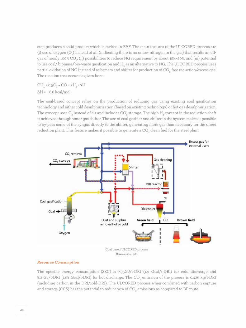
48
step produces a solid product which is melted in EAF. The main features of the ULCORED process are (i) use of oxygen (O2) instead of air (indicating there is no or low nitrogen in the gas) that results an off-gas of nearly 100% CO2, (ii) possibilities to reduce NG requirement by about 15%–20%, and (iii) potential to use coal/ biomass/bio-waste gasification and H2 as an alternative to NG. The ULCORED process uses partial oxidation of NG instead of reformers and shifter for production of CO2-free reduction/excess gas. The reaction that occurs is given here:
CH4 + 0.5O2 = CO + 2H2 +∆H
∆H = – 8.6 kcal/mol
The coal-based concept relies on the production of reducing gas using existing coal gasification technology and either cold desulphurization (based on existing technology) or hot gas desulphurization. The concept uses O2 instead of air and includes CO2 storage. The high H2 content in the reduction shaft is achieved through water gas shifter. The use of coal gasifier and shifter in the system makes it possible to by-pass some of the syngas directly to the shifter, generating more gas than necessary for the direct reduction plant. This feature makes it possible to generate a CO2 clean fuel for the steel plant.
Excess gas forexternal users
Gas cleaning
DRI reactor
DRI cooler
DRIGreen �eld Brown �eld
Shifter
CO2 removal
CO2 storage
Coal gasification
Coal
Oxygen
Dust and sulphurremoval hot or cold
Resource Consumption
The specific energy consumption (SEC) is 7.95GJ/t-DRI (1.9 Gcal/t-DRI) for cold discharge and 8.3 GJ/t-DRI (1.98 Gcal/t-DRI) for hot discharge. The CO2 emission of the process is 0.435 kg/t-DRI (including carbon in the DRI/cold-DRI). The ULCORED process when combined with carbon capture and storage (CCS) has the potential to reduce 70% of CO2 emissions as compared to BF route.
Coal based ULCORED processSource: Steel 360

49
4.3 Direct Reduction of Iron Production Using Gas Route4.3.1 MIDREX NG Process
MIDREX NG uses MIDREX reformer to produce reducing gases for iron ore reduction reactions in the shaft furnace. Iron ore (either lumps or pellets), charged from the top of the shaft furnace, is reduced and discharged from the bottom of the furnace. The reductant gas entering at the middle of the furnace reduces the raw material to iron metal and leaves from the top of the furnace. The cooling gas, which circulates at the lower portion of the furnace, cools the DRI to about 50°C. The charging port and discharging port are dynamically sealed by a sealing gas, thereby allowing continuous charging and discharging processes. The reactions occurring in the shaft furnace are as follows:
Fe2O3 + 3CO 2Fe + 3CO2
Fe2O3 + 3H2 2Fe + 3H2O
Top gas
Top gasscrubber
Top gas fuelCombustionair
Process gas
Process gascompressor
Natural gas
Naturalgas
Feedgas
Flue gas
Top gas fuel/Combustion air
Feed gas
Natural gas
Hot fanand stack
Flue gas Flue gas
MIDREXshaft
furnaceMIDREX
ReformerMIDREX
Heat recovery system
CDRI / HBI / HDRI
Iron oxide
Reducinggas
MIDREX NG processSource: MIDREX
The exhaust gas (top gas) emitted from the top of the shaft furnace is cleaned and cooled by a wet scrubber (top gas scrubber) and recirculated for reuse. The top gas, containing CO2 and H2O, is pressurized by a compressor and, after mixing with natural gas, is preheated and fed into the reformer furnace. The

50
reformer furnace comprises reformer tubes filled with nickel catalyst. On passing through these tubes, the mixture is reformed to produce reductant gas. The reactions occurring in the reformer are as follows:
CH4 + CO2 2CO + 2H2
CH4 + H2O CO + 3H2
2CH4 + O2 2CO + 4H2
CO + H2O CO2 + H2
CH4 C(s) + 2H2
The typical composition of reducing gas comprises 55% of H2 and 36% of CO (H2 /CO ratio ~1.5). The MIDREX plant with other syngas can operate with a H2/CO ratio between 0.4 and 3.5. In addition to providing the reducing gas, the reformer also provides the energy needed for the reduction reactions within the shaft furnace. The MIDREX process has the flexibility to use coke oven gas and other reducing gases derived from petcoke.
To improve the SEC and productivity of the plant, including the downstream steelmaking process, it is possible to discharge hot DRI (HDRI) or make hot-briquetted iron (HBI). HBI is made by compressing DRI discharged from the MIDREX shaft furnace at ≥ 650°C into pillow-shaped briquettes with a typical size of 30 × 50 × 110 mm and a density ≥ 5 gm per cc. No binder is used to make HBI. The HBI is the preferred product for the merchant metallics market as it is denser than cold DRI, which reduces the re-oxidation rate. This enables HBI to be stored and transported without special precautions for shipping solid bulk cargoes. HBI can be used in EAF, BF, and BOF. HDRI with temperature up to 650°C can be transferred to an adjacent EAF for utilizing the sensible heat.
4.3.2 MIDREX H2 Process
The natural gas-based MIDREX process, coupled with an EAF, has the lowest CO2 emission of any steelmaking route using iron ore. There is room to further decrease emissions by using hydrogen as a fuel and chemical reactant in the process. One of the best options available in the near future is to use hydrogen to produce DRI as feedstock for steelmaking, which is known as MIDREX H2. At present, due to non-availability of hydrogen at sufficient scale it is not possible to transit from coal/NG to hydrogen. However, in the existing MIDREX NG process, up to 30% of NG can be replaced with hydrogen without any change in the existing process. In future, as and when the use of hydrogen becomes economically
Benefits of HDRI
The use of HDRI in EAF helps in the following:
� Reduces electricity consumption (20 kWh per tonne liquid steel for each 100°C increase in DRI charging temperature).
� Shorter overall melting cycle, resulting in reduction in electrode consumption (by at least 0.5–0.6 kg per tonne liquid steel).
� Decreases refractory consumption (1.8–2 kg per tonne liquid steel).

51
MIDREXShaft
furnace
HDRI
Top gasscrubber
Process gascompressor
Main airblower
Flue gas
Flue gasstack
Recuperator(optional)
Iron Oxide
Reducing gas
Reduction gasheater
Combustion air
Oxygen
Energy
Hydrogen(Make-up)
MIDREX H2 processSource: MIDREX
4.3.3 HYL
The HYL reactor and its peripheral systems and principles of operation are same as described for coal gas-based system in Section 4.2.2. The iron ore is fed from the top and is reduced by a counter-current flow of gas containing H2 and CO. The furnace top gas is cooled, cleaned, and its CO2 is captured and recycled into reducing gas circuit. The reducing gases can be generated (i) directly, by in-situ reforming of natural gas inside the shaft furnace, (ii) in an external natural gas/steam reformer, (iii) as syngas from gasification of fossil fuels, biomass, etc., (iv) from exhaust gas of smelting reduction process such as COREX, or (v) from coke-oven gas (COG) sources. In all the cases, the process configuration corresponds to the same basic zero reformer (ZR) schemes, adjusting the relative sizes of equipment for the particular application.
Energiron ZR
The ENERGIRON ZR process scheme is the latest achievement in reducing the size and improving the efficiency of direct reduction plants. The process is fed by NG and reducing gases are generated by in-situ reforming within the reduction reactor without any requirement for the reformer. The elimination
viable, it can be increased in the process with minor equipment modifications. It is possible to use 100% hydrogen in the reactor by optimizing the carbon in DRI in the melt shop. For a DRI output with 1.4% carbon, the typical bustle gas composition is about 90% hydrogen and the balance is a mixture of CO, CO2, H2O, and CH4. The typical consumption of hydrogen is approx. 650 Nm3/t-DRI (54 kg/t).
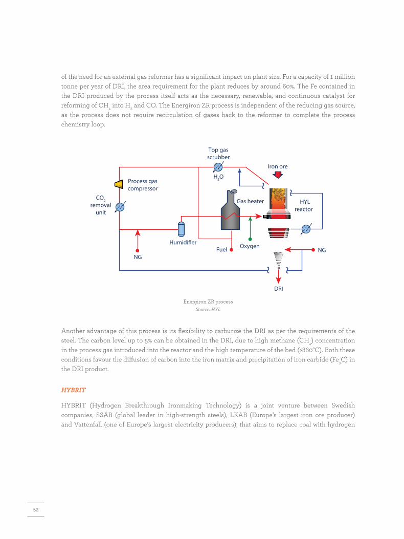
52
H2O
CO2removal
unit
Process gascompressor
Fuel
HYLreactor
Top gasscrubber
Iron ore
NGNG
Oxygen
DRI
Gas heater
Humidi�er
Energiron ZR processSource: HYL
Another advantage of this process is its flexibility to carburize the DRI as per the requirements of the steel. The carbon level up to 5% can be obtained in the DRI, due to high methane (CH4) concentration in the process gas introduced into the reactor and the high temperature of the bed (>860°C). Both these conditions favour the diffusion of carbon into the iron matrix and precipitation of iron carbide (Fe3C) in the DRI product.
HYBRIT
HYBRIT (Hydrogen Breakthrough Ironmaking Technology) is a joint venture between Swedish companies, SSAB (global leader in high-strength steels), LKAB (Europe’s largest iron ore producer) and Vattenfall (one of Europe’s largest electricity producers), that aims to replace coal with hydrogen
of the need for an external gas reformer has a significant impact on plant size. For a capacity of 1 million tonne per year of DRI, the area requirement for the plant reduces by around 60%. The Fe contained in the DRI produced by the process itself acts as the necessary, renewable, and continuous catalyst for reforming of CH4 into H2 and CO. The Energiron ZR process is independent of the reducing gas source, as the process does not require recirculation of gases back to the reformer to complete the process chemistry loop.

53
Blast furnace route HYBRIT route
Pelletizing
Iron orepellets
Iron oreconcentrate
Hotmetal
Crude steel
Spongeiron
Iron orepellets
Ironmaking
Steelmaking
CO2
Coal
Fossil fuels
Hot blastcoal, oxygen
Oxygen
Coke plant
Coke
Non-fossil fuels
Scrap
HydrogenHydrogen storage
Hydrogen plant
Hydrogenand water Electricity
CO2
CO2
Comparison of blast furnace route and HYBRIT routeSource: HYBRIT
in steelmaking process. In this process, iron metal is produced by using hydrogen gas as the main reductant. The production route is similar to existing DR processes, except for CO2 emissions. Hydrogen reacts with iron oxides to form water instead of carbon dioxide. In the demonstration project in Sweden, hydrogen will be produced by electrolysis of water using fossil-free electricity.

54
4.4 Hydrogen Use in Indian Iron and Steel SectorWith growing economy, the Indian iron and steel sector is set to grow rapidly over the coming decades. As per TERI’s analysis under a low-carbon scenario, the steel demand will rise to around 300 million tonne by 2050. To meet this demand in a sustainable manner, it is important that the low-carbon pathways are deployed for new capacity addition. Owing to cumulative impact of the factors such as falling cost of renewable electricity and electrolyser technologies, coupled with concerted and more coordinated action on climate change, TERI assesses that in the long run hydrogen direct reduction is amongst the most promising options for Indian steel sector to grow sustainably.
0BF- BOF
CAPEX FIXED OPEX Fuel Raw matrerials CCUS Range
Coal DR-EAF NG DR-EAF SR-BOF CCUS H2 DR-EAF
100
200
300
Cost
of p
rodu
ctio
n ($
/t)
400
500
600Conventional Low-Carbon
Costs of production from various routes, 2020Sources: TERI analysis based on IEA (2019); BNEF (2020); sector experts
Costs of steel production - H2 -DR vs SR-BOF with CCUS routesSources: TERI analysis based on IEA (2019; Hall, Spencer, and Kumar (2020); BNEF (2020)
$80/tCO2
CCUS cost
$20/tCO2
0
100
200
300
400
Cost
of p
rodu
ctio
n ($
/t)
500
600
700 2050
0 1
SR-BOF CCUS H2 DR-EAF
2 3
Hydrogen Cost ($/kg)
4 5 6
2030

55
A stepwise approach to reduce CO2 emissions via the direct reduction route.
The pilot plants using high shares of low-carbon hydrogen are already being established in Europe. The HYBRIT project in Sweden recently started with the demonstration plant (September 2020) and aims to have a commercial-scale plant up and running by 2026, with the intention to switch over their entire fleet by 2045 (SSAB 2019).
If supplied with zero-carbon hydrogen and combined with an EAF supplied with zero-carbon electricity, the hydrogen direct reduction route has the potential to reduce emissions by over 94% compared with conventional technologies. Residual emissions occur with the use of graphite electrodes in the EAF. This holds true with the utilization of lime and natural gas as well. Emissions could be brought down to zero with further research and development.
Hydrogen is already used extensively in India, mainly as an industrial feedstock in the creation of ammonia-based fertilizers. Therefore, the capacity to handle and use hydrogen at industrial scale is already available in the country. The main barriers relate to cost of low-carbon hydrogen and access to renewable electricity. The conventional routes will likely be cheaper in the near term, driven mainly by the lower input costs and lack of infrastructure for carbon capture utilization and storage (CCUS). As per TERI’s analysis, the cost of hydrogen-based direct reduction will start to be competitive with smelting reduction – basic oxygen furnace along with CCUS by 2030.
Step 1Commissioning a NG
based DR plant
Step 2Blending up to 30%
green hydrogen
Step 3Complete switch over to100% green hydrogen
In the journey of low-carbon steel production in the long run, NG can play a crucial role as a transition technology for the steel sector. The key technology providers are already promoting NG to H2 transition as a route to deep decarbonization.
To facilitate the increased use of hydrogen in the steel sector, the following three key issues need to be addressed:
(i) Enabling policy framework for promoting hydrogen production and use in the steel sector.
(ii) Facilitating establishment of pilot and demonstration plants to familiarize the industry with the H2-DR process, address any technical issues, and build-up the confidence of the industry.
(iii) Access to green finance to enable large-scale investments by steel manufacturers.

57
CONCLUSION5
58
Steel industry is one of the most important sectors and contributes significantly to the growth of a country as various industrial and construction activities are closely linked with the steel sector. India is the second-largest producer of steel on a global scale and direct reduction of iron (DRI) sector contributes significantly to the overall production of steel in India. DRI/sponge iron through the reduction of iron ore using non-coking coal or natural gas as reductant was developed as a substitute for ferrous scrap. Initially sponge iron manufacturing gained prominence in India owing to short supply and high prices of scrap, low-technology barriers, and a high presence of EAF plants in the domestic market.
The Indian DRI sector accounts for about 39.3% of the total global production (WSA 2020). Most of the Indian DRI plants use coal-based processes due to less investment, lower-gestation period, easy availability of coal, and limited accessibility of gas. The overall capacity utilization of the DRI plants stands low, at about 60%. The poor quality of iron ore further results in lower yield of the sector. The specific energy consumption (SEC) of DRI production of coal-based rotary kiln varies in the range of 4.10–5.26 Gcal/t averaging about 4.51 Gcal/t. There is a significant potential among the coal-based DRI plants to adopt energy-efficient technologies. Of these, one of the most attractive options is waste heat recovery (WHR)-based power generation, particularly for plant capacities of 200 tpd and above. Smaller capacity plants, for example, 100 tpd or less, can adopt other WHR options such as iron ore preheating and coal drying, which can improve the energy performance substantially.
Apart from WHR-based technologies, the other energy-efficiency options include switch over to iron ore pellets, mullite-based lining, accretion reduction, coal gasification for partial substitution of coal, and use of energy-efficient electrical systems. These energy-efficiency options along with WHR-based recovery systems can lead to a reduction in SEC level of 2.3 Gcal/t-DRI.
Considering the projected growth of steel sector in India, it is expected that the DRI route will continue to play a significant role in the country. Accordingly, it is important that DRI plants improve their energy and environmental performance. In addition to adopting viable energy-efficient technological options in the existing processes, the new DRI capacities must explore and focus on adoption of low-carbon technologies. The process requirements can either be met through coal gasification or natural gas reforming routes, which are commercially available. In long-term, carbon neutral DRI production can be established through adoption of hydrogen route, which is presently under development and being explored internationally.
A summary of energy-efficient technology options for Indian DRI sector is tabulate here. The energy saving is quantified considering a plant capacity of 100 tpd and coal with a calorific value of 5200 kcal per kg. For WHR-based power generation, energy saving has been estimated considering a plant capacity of 200 tpd.

59
Summary of energy-efficient technology options for rotary kiln-based DRI industry
S. No. Energy-efficient technology Energy saving (Gcal/year)
Investment (Rs lakh)
Payback (year)
GHG reduction (tCO2/year)
1 WHR – power generation 20,227 2800 3.2 19,286
2 WHR– iron ore preheating 22,360 350 1.3 7,726
3 Coal gasification for partial substitution 21,840 NA - 7,546
4 WHR – vapour absorption chiller 36 7 2.0 34
5 Decentralized VFDs for shell air fans 16 3 5.2 16
6 Mullite-based kiln lining 3,033 150 4.1 1,048
7 Switch over to iron ore pellets 27,300 - - 9,433
8 WHR – coal moisture reduction 5,539 100 1.5 1,914
9 Energy-efficient motors 19 3 4.8 18
10 Energy-efficient pumps 72 2 0.8 69
11 VFDs for air compressors 71 3 1.3 67
12 FRP blades for cooling tower fans 9 0.7 2.4 8
13 Thermostatic controller for cooling tower 12 0.2 0.4 11
NA – not available

60
Vendor Contact details
WHR-based power plant
Popuri Engineering Services Private Limited 12-2-460/2 Sai Sudha Nilayam New HUDA Layout Gudimalkapur, Mehdipatnam Hyderabad –500 028, Andhra Pradesh Phone : (040) 23510649, 23510844, 23513468 Fax : (040) 23510111 http://popurigroup.com
Thermax Limited No. D13, MIDC Industrial Area, RD Agra Road, Chinchwad Pimpri, Chinchwad– 411019 https://www.thermaxglobal.com
WHR-based preheating system (iron ore and coal)
Popuri Engineering Services Private Limited 12-2-460/2 Sai Sudha Nilayam New HUDA Layout Gudimalkapur, Mehdipatnam Hyderabad –500 028, Andhra Pradesh Phone : (040) 23510649, 23510844, 23513468 Fax : (040) 23510111 http://popurigroup.com
Iron ore pelletizer plant
Popuri Engineering Services Private Limited 12-2-460/2 Sai Sudha Nilayam New HUDA Layout Gudimalkapur, Mehdipatnam Hyderabad – 500 028, Telangana Tel : (040) 23510649, 23510844, 23513468 Fax : (040) 23510111 http://popurigroup.com
Technology Vendors – Energy-efficient Equipment and SystemsThe energy-efficiency improvements in DRI sector would require significant modifications and adoption of commercially available energy-efficient and state-of-the-art technologies in the process. A select list of key technology vendors for energy-efficient technologies in DRI process and associated auxiliary system is provided here.

61
Vendor Contact details
Outotech Balaji Building No. 3, Ground Floor, Hennur Main Road, Opposite Kothanur PO, Kothanur V&P Bengaluru – 560077, Karnataka Tel: (080) 2308 1600
South City Pinnacle, 12th Floor, Sector V Block EP, Salt Lake, Kolkata – 700 091, West Bengal Tel: (033) 4014 0400
FLSmidth Private Limited Plot No. 34, Egatoor, Near Rajiv Gandhi Salai, Kelambakkam, Chennai – 603103, Tamil Nadu Tel: (044) 4748 1000
Mesto India Private Limited 44 Park Street, 3rd Floor, Saket Building, Kolkata – 700 016, West Bengal Tel: (33) 3025 4611
1404, 14th Floor, Rupa Solitaire, Millennium Business Park, Thane-Belapur Road, Mahape – 400 710 Navi Mumbai Tel: (22) 61221800
Kobelco 2-4, Wakinohama-Kaigandori 2-chome, Chuo-ku, Kobe, Hyogo, 651-8585, Japan Tel: +81-78-261-5111 Fax: +81-78-261-4123 https://www.kobelco.co.jp/english/
Coal gasification
Nippon Steel Engineering Plant and Machinery Division Osaki Center Building, 1-5-1, Osaki, Shinagawa-ku Tokyo 141-8604 Japan Tel: +81-3-6665-2000 Fax: +81-3-6665-4847 https://www.eng.nipponsteel.com/english/whatwedo/steelplants/ironmaking/direct_reduced_iron_process/
Vapour absorption machines
Thermax India Limited Energy House, D-II Block, Plot No. 38 & 39, MIDC Area, Chinchwad, Pune – 411 019, Maharashtra, India Fax: +91-20-6730 8948. Tel: +91-20- 67308915 www.thrmaxindia.com

62
Vendor Contact details
Transparent Energy Systems Private Limited Ist floor, Pushpa Height, Bibwewadi Corner Pune – 4011037, Maharashtra www.tespl.com
Insulation
Lloyds Insulation 6 Middleton Street, Kolkata –700071, West Bengal Tel: (033) 3058 5214 http://lloydinsulations.com/ http://lloydinsulations.com/CompanyLocation.aspx
Murugappa Morgan Thermal Ceramics Limited
Dare House, NSC Bose Rd, Parry’s Corner, George Town, Chennai– 600001 Tamil Nadu, India www.murugappa.com
Rockwool (India) Limited Plot No. 21 and 22, 1st Floor, Century Building Rohini Layout, Madhapur Hyderabad – 500084, Telangana Tel: 040-30408650 www.rockwoolindia.com
Motors
ABB India ABB Ahmedabad Office, 5th Floor, A-6 Safal Profitaire, Corporate Road, Ahmedabad – 380015, Gujarat Tel: +91 96 2436 0600
Crompton Greave Limited No. 50, 5th and6th Floors, Lisco House, Chowringhee Road, Middleton Row, Kolkata –700071, West Bengal
Kirloskar Brothers Limited M-11, 3rd floor, Middle Circle, Connaught Place, New Delhi –110 001 Tel: 011 – 41501056 www.kirloskarpumps.com
Siemens Limited Birla Aurora, Level 21, Plot No. 1080, Dr Annie Besant Road, Worli, Mumbai – 400030, Maharashtra Tel: 022-39677000
Variable frequency drives
ABB India Limited ABB Ahmedabad Office, 5th Floor, A-6 Safal Profitaire, Corporate Road, Ahmedabad – 380015, Gujarat Tel: +91 96 2436 0600

63
Vendor Contact details
Siemens India Limited Birla Aurora, Level 21, Plot No. 1080 Dr Annie Besant Road, Worli, Mumbai – 400030 Tel: (022) 39677000
Apex Industries No. 5, Mathura Road, Old Faridabad, Faridabad – 121002, Haryana
FUJI Electric India Private Limited 78 A, Park St, Mallik Bazar, Park Street area, Kolkata – 700017, West Bengal
Schneider Electric India Private Limited DLF Building, Tower C, N-10, DLF Cyber City, DLF Phase 2, Sector 24 Gurugram – 122002, Haryana
Energy-efficient pumps
KSB Pumps limited KSB Pumps Limited, KSB House, A-96, Sector IV Dist. Gautam Budh Nagar NOIDA – 201 301, Uttar Pradesh Tel: (120) 2541 091 Fax: (120) 2550 567
Kirloskar Brothers Limited M-11, 3rd Floor, Middle Circle, Connaught Place, New Delhi –110 001 Tel: 011 – 41501056 Email: [email protected]
Grundfos Pumps India Private Limited 118 Rajiv Gandhi Salai, Thoraipakkam, Chennai – 600 097, Tamil Nadu Tel: (044) 4596 6800 Fax: (44) 4596 6969 Toll Free : 1800 345 4555 Email: [email protected]
Cooling tower fan control (thermostatic)
Delta Cooling Towers Private Limited 1st Floor, Bhagwati Sadan, Plot No. 8, Community Centre, BH Block, Shalimar Bagh, Delhi – 110088 Tel: +91-11-27495801/27495802/27495803 Fax: +91-11-27495804 Email: [email protected], [email protected]
Airtech Cooling Process Private Limited 145A, HSIIDC Internal Road, Sector 31, Faridabad – 121003, Haryana Tel: (129) 4177211/ 4177212 Fax: (129) 4177213 Mobile : 9350511679 E-mail: [email protected], [email protected]

64
Vendor Contact details
Fibre-reinforced plastic (FRP) fan blades
Delta cooling towers Private Limited 1st Floor, Bhagwati Sadan, Plot no. 8, Community Centre, BH Block, Shalimar Bagh, Delhi –110088 Tel: +91-11-27495801 / 27495802 / 27495803 Fax: +91-11-27495804 Email: [email protected], [email protected]
Paharpur Cooling Towers Limited Paharpur House 41 Cunningham road cross Bengaluru –560052, Karnataka Tel: (080) 2226 5566-7, 2234 1911 Email: [email protected]
Himgiri Cooling Tower 2/320, Mahesh Industrial Estate, Opposite Silver Park, Mira Road (East), Mumbai – 401104, Maharashtra Tel: (022) 2811 0937, 2811 8581 Email: [email protected]
Airtech Cooling Process Private Limited 145A, HSIIDC Internal Road, Sector 31, Faridabad –121003, Haryana Tel: (0129) 4177211/ 4177212 Fax: (0129)-4177213 Mobile: 9350511679 E-mail : [email protected], [email protected]
Automatic power factor controller
ABB India Bengal Intelligent Park Limited, Omega Blk EP and GP, Sector V, Salt Lake City, Kolkata –700091, West Bengal
Sai Electricals 301, Czar Woods, Om Gardens, Maitree Vihar, Chandrashekharpur, Bhubaneswar – 751 023, Odisha Tel: (0674) 2301141, 2301288 E-mail: [email protected] http://saielectricals.com/contact-us/
Siemens Limited Birla Aurora, Level 21, Plot No. 1080, Dr Annie Besant Road, Worli, Mumbai – 400030, Maharashtra Tel: (022) 39677000
Schneider Electric India DLF Building, Tower C, N-10, DLF Cyber City DLF Phase 2, Sector 24 Gurugram – 122002, Haryana

65
REFERENCES
Battle T., J. McClelland, et. al. 2014. Treatise on Process Metallurgy: industrial processes. Details available at <https://www.sciencedirect.com/topics/engineering/direct-reduced-iron>, last accessed on 17 July 2020
Bureau of Energy Efficiency. 2018. Energy Conservation Guidelines for Industries: MSME sector CASE. 2020. Gasifier for DRI Rotary Kiln. Details available at <http://www.casepl.com/GasifierForDRIRotaryKiln.html>, last accessed on 10 July 2020
Chandrakant B. P. and V. B. Jaware. 2015. Review on Use of Vapour Absorption Machine (VAM) Using Waste Heat in a Paint Shop. International Journal of Engineering Research and Technology 4 (4) ISSN: 2278-0181
Details available at <http://popurigroup.com/pecs_ourServices.html>, last accessed on 20 July 2020
Details available at <http://spongeitc.com/services5_rnd1.htm>, last accessed on 20 July 2020
Details available at <https://www.tflhouston.com/2018/10/12/what-is-mullite>, last accessed on 28 April 2020
Duarte, P, E. n.d. HYL Direct Reduction Technology: adaptations for the Indian market. Details available at <https://www.energiron.com/wp-content/uploads/2019/05/2004-HYL-Direct-Reduction-Technology-Adaptations-for-the-Indian-Market.pdf>
Dutta, S. K. and R. Sah. 2016. Direct Reduced Iron: production. Encyclopedia of Iron, Steel, and their Alloys. Taylor and Francis: New York, Published online: 30 March 2016, pp. 1082–1108. Details available at https://www.researchgate.net/publication/ 305350936_i_ Direct_Reduced_Iron_Production, last accessed on 21 May 2020
DRI Products and Applications: providing flexibility for steelmaking. 2018. Details available at: https://www.midrex.com/wp-content/uploads/MIdrexDRI_Products Brochure_4-12-18-1.pdf
Energiron. 2020. Brochure. Details available at <https://www.energiron.com/wp-content/uploads/2020/01/Energiron_Brochure-2020.pdf>
Energiron ZR. Details available at <https://www.energiron.com/energiron-zr/>
Energiron. 2008. Iron and Steel Review. 51 (8). Details available at <https://www.energiron.com/wp-content/uploads/2019/05/2008-Iron-Steel-Review-Article.pdf>, last accessed on January 2008
Features of FASTMET Process. Details available at <https://www.kobelco.co.jp/english/ktr/pdf/ktr_29/085-092.pdf>, last accessed on 15 May 2020
Gasification Technologies Conference, San Francisco, California, USA. 1999. Gasification and the MIDREX direct reduction process. Details available at <https://www.globalsyngas.org/uploads/eventLibrary/GTC99260.pdf>
Hall, W., T. Spencer, and S. Kumar. 2020. Towards a Low-carbon Steel Sector: an overview of the changing market, technology, and policy context for Indian steel. Details available at https://www.teriin.org/project/decarbonization-iron-and-steel-sectors
Hybrit: Towards Fossil-free Steel. 2017. Details available at <https://ssabwebsitecdn.azureedge.net/-/media/hybrit/files/hybrit_brochure.pdf?m=20180201085027>
66
Hydrogen Steelmaking. Sustainable Energy Economy Workshop. Toledo, OH. Details available at <https://www.utoledo.edu/engineering/research/pdfs/3.Chevrier.pdf<, last accessed on 14 July 2020
HYL Process for Direct Reduction of Iron Ore. 2017. Details available at <https://www.ispatguru.com/hyl-process-for-direct-reduction-of-iron-ore/#:~:text=Energiron%20direct%20reduction%20process%20(HYL,gas%20moving%20bed%20shaft%20furnace>, last accessed on 22 July 2020
Institute for Industrial Productivity. 2009. Industrial Efficiency Technology Data Base: direct reduced iron. Details available at <http://www.iipinetwork.org/wp-content/Ietd/content/direct-reduced-iron.html>, last accessed on 22 July 2020]
Ishikawa, H., J. Kopfle, J. Mcclelland, and J. Ripke. 2008. Rotary Hearth Furnace Technologies for Iron ore and Recycling Applications. Archives of Metallurgy and Materials 53 (2). Details available at <http://www.imim.pl/files/archiwum/Vol2_2008/artykuly/Ishikawa.pdf>
Ispat Guru. 2017. Coal based Direct Reduction Rotary Kiln Process. Details available at <https://www.ispatguru.com/coal-based-direct-reduction-rotary-kiln-process/#>, last accessed on 10 July 2020
Ispat Guru. 2017. Coal Gasification-based Production of Direct Reduced Iron. Details available at <https://www.ispatguru.com/coal-gasification-based-production-of-direct-reduced-iron/>, last accessed on 10 July 2020
Ispat Guru. 2020. Introduction to Iron Ore Pellets and Pelletizing Processes. Details available at <https://www.ispatguru.com/iron-ore-pellets-and-pelletizing-processes>, last accessed on 29 April 2020
ITmk3® Process Summary. Details available at <https://www.kobelco.co.jp/english/products/ironunit/itmk3.html>
Kekkonen, M. and E. L. Holappa. 2000. Comparison of Different Coal-based Direct Reduction Processes. Helsinki University of Technology. Details available at <https://www.researchgate.net/publication/269107176_COMPARISON_OF_DIFFERENT_COAL_BASED_DIRECT_REDUCTION_PROCESSES>, last accessed on 18 August 2020
Kobelco Technology Review. 2010. Details available at https://www.kobelco.co.jp/english/ktr/pdf/ktr_29/050-057.pdf>, last accessed on 29 June 2020
MIDREX. 2020. Sustainable Energy Economy Workshop. Details available at https://www.utoledo.edu/engineering/research/pdfs/3.Chevrier.pdf, last accessed on 14 January 2020
MIDREX H2: Ultimate low CO2 ironmaking and its place in the new hydrogen economy. 2017. Details available at < https://www.midrex.com/tech-article/midrex-h2-ultimate-low-co2-ironmaking-and-its-place-in-the-new-hydrogen-economy/>, last accessed on September 2017
MIDREX NG: optimizing DRI production using natural gas. 2018. Details available at <https://www.midrex.com/wp-content/uploads/MIDREX_NG_Brochure_4-12-18.pdf>
MIDREX Technologies, Inc. 2018. World Direct Reduction Statistics 2018. Details available at <https://www.midrex.com/wp-content/uploads/Midrex_STATSbookprint_2018Final-1.pdf>, last accessed on 8 July 2020
Ministry of Steel. An Overview of Steel Sector. Details available at <https://steel.gov.in/sites/default/files/An%20Overview%20of%20Steel%20Sector_may2019.pdf> Ministry of Steel. 2020. Annual Report 2019/20. Details available at <https://steel.gov.in/sites/default/files/Annual%20Report-Ministry%20of%20Steel%202019-20.pdf>
MXCOL: Using SYNGAS to make DRI in MIDREX process. 2014. Details available at <https://www.midrex.com/wp-content/uploads/MXCOL.pdf>
67
National Productivity Council. 2017. Best practices manual for reducing GHG emissions in iron and steel (sponge iron) sector. Details available at <https://npcindia.gov.in/NPC/Files/delhiOFC/GHG-Manual-Iron-Steel-Final.pdf>, last accessed on 6 August 2020
Prospects of Coal-based Direct Reduction Process. Details available at <https://pdfs.semanticscholar.org/eaf6/a4a73a3932ea45a8b03760c170e5369fd24f.pdf/>, last accessed on 29 June 2020
Sandra Lúcia de Moraes, José Renato Baptista de Lima, and Tiago Ramos Ribeiro. 2020. Iron Ore Pelletizing Process: an overview. Details available at <https://cdn.intechopen.com/pdfs/58868.pdf>, last accessed on 29 April 2020
Sponge Iron Manufacturers Association. 2018. DRI Update, December 2018 Singh, A. and P. Jain. 2015 (Nov.–Dec.). A study on the Accretion Formation in DRI Kilns and Possible Ways for its Reduction. IOSR Journal of Mechanical and Civil Engineering 12 (6): 98–103
Steel 360 Article on ULCORED Process. 2019. Details available at <https://www.steel- 360.com/technology-next/ulcored-process>
The Energy and Resources Institute. 2020. Make Hydrogen in India. Driving India Towards the Clean Energy Technology Frontier. Details available at <https://www.teriin.org/sites/default/files/2020-06/Hydrogen-Policy-Brief.pdf>
Tenova. Iron Reduction Technologies. Details available at <https://www.tenova.com/product/iron-reduction-technologies/> Tenova and Danieli. Details available at <https://www.energiron.com/wp-content/uploads/2020/01/ENERGIRON-Presentation.pdf>
Thermax Limited. 2020. Vapour Absorption Chiller. Retrieved Details available at <https://www.thermaxglobal.com/absorption-cooling/vapour-absorption-chillers/tripple-effect-chiller-2/>, last accessed on 22 July 2020
The MIDREX® Process. Details available at <https://www.midrex.com/wp-content/uploads/MIdrex_Process_Brochure_4-12-18.pdf>
The World’s Most Reliable and Productive Direct Reduction Technology. 2018.
United Nations Development Programme. 2018a. Multimedia Tutorials on Energy-efficient Technologies and Practices in Direct Reduced Iron Sector, Installation of Automation and Control System in DRI Kiln [accessed on 22 July 2020]
United Nations Development Programme. 2018b. Energy-efficient Technologies for Small-scale Steel Sector in India – a ready reckoner
World Steel Association. 2020. World Steel in Figures. Details available at https://www.worldsteel.org/en/dam/jcr:f7982217-cfde-4fdc-8ba0-95ed807f513/World%2520Steel%2520in%2520Figures%25202020i.pdf
17th Annual International Steel Seminar and Exhibition Kolkata. 2010. Coal gasification based DRI solution for Indian ironmaking. Details available at <http://www.midrex.com/wp-content/uploads/Midrex_Paper_Jan_2010_Kolkata_Conference.pdf>

THE ENERGY ANDRESOURCES INSTITUTE
Creating Innovative Solutions for a Sustainable Future