Energy and Flow Measurement for Hydronic · PDF filePresented By: George Szyszko Applications...
58
Presented By: George Szyszko Applications Consultant MCR for ONICON Incorporated Energy and Flow Measurement for Hydronic Systems
Transcript of Energy and Flow Measurement for Hydronic · PDF filePresented By: George Szyszko Applications...

Presented By:
George Szyszko
Applications Consultant
MCR for ONICON Incorporated
Energy and Flow Measurement
for Hydronic Systems
Why Measure Thermal Energy?
To control something, you must first
measure it…
Lord Kelvin
Non-Electric Utilities:
Chilled Water, Hot Water, Condenser Water
Saturated Steam
Natural Gas & Compressed Air

Typical Btu Measurement Applications
Campus
Environments
Metering each building
provides:
•Basis for cost allocation
•Growth planning data
•Promotes conservation
•Basis for LEED points

Campus Applications Building Tertiary Loops
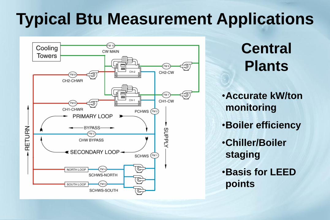
Typical Btu Measurement Applications
Central
Plants
•Accurate kW/ton
monitoring
•Boiler efficiency
•Chiller/Boiler
staging
•Basis for LEED
points

Typical Btu Measurement Applications
Submetering
Within Buildings

Hydronic Cooling/Heating System
Heat Load Calculation: Btu Rate = Flow Rate x Delta-T x Specific Heat x Density

Btu Measurement Accuracy Evaluation Sources of Error Using Traditional Methods
• Flow – Meter accuracy
– Signal D/A conversion
– Control input offset
• Temperature – Sensor accuracy
– Transmitter accuracy
– Sensor matching
– Signal transmission error
– Control input offset
• Resolution
– Of inputs
– Of calculations
• Specific heat
corrections
• Density corrections
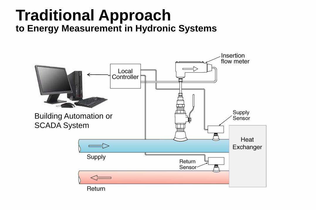
Building Automation or
SCADA System
Traditional Approach to Energy Measurement in Hydronic Systems
Btu Measurement Accuracy Evaluation Potential Cost of Measurement Error
The effect of using typical HVAC grade
flow and temperature sensors into
standard analog control system inputs for
energy measurement is widely
misunderstood.
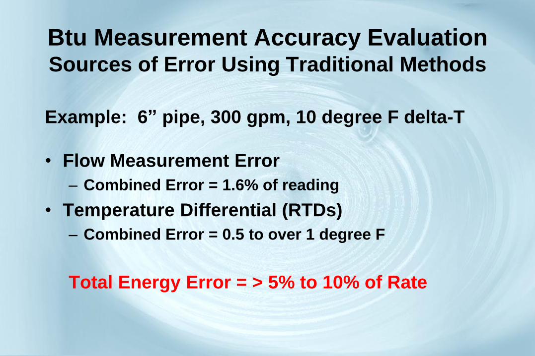
Btu Measurement Accuracy Evaluation Sources of Error Using Traditional Methods
Example: 6” pipe, 300 gpm, 10 degree F delta-T
• Flow Measurement Error
– Combined Error = 1.6% of reading
• Temperature Differential (RTDs)
– Combined Error = 0.5 to over 1 degree F
Total Energy Error = > 5% to 10% of Rate
Btu Measurement
With a Factory-Calibrated System
Btu Meter, Flow Meter and Matched Temperature Sensors Installed as a Complete, Factory-Calibrated System
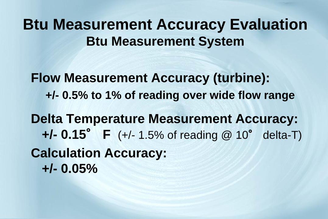
Btu Measurement Accuracy Evaluation Btu Measurement System
Flow Measurement Accuracy (turbine):
+/- 0.5% to 1% of reading over wide flow range
Delta Temperature Measurement Accuracy:
+/- 0.15° F (+/- 1.5% of reading @ 10° delta-T)
Calculation Accuracy:
+/- 0.05%
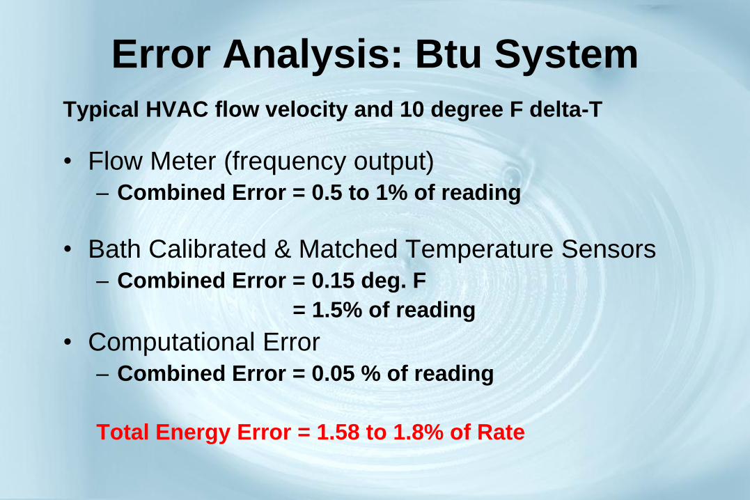
Error Analysis: Btu System
Typical HVAC flow velocity and 10 degree F delta-T
• Flow Meter (frequency output) – Combined Error = 0.5 to 1% of reading
• Bath Calibrated & Matched Temperature Sensors – Combined Error = 0.15 deg. F
= 1.5% of reading
• Computational Error – Combined Error = 0.05 % of reading
Total Energy Error = 1.58 to 1.8% of Rate

Btu Measurement System
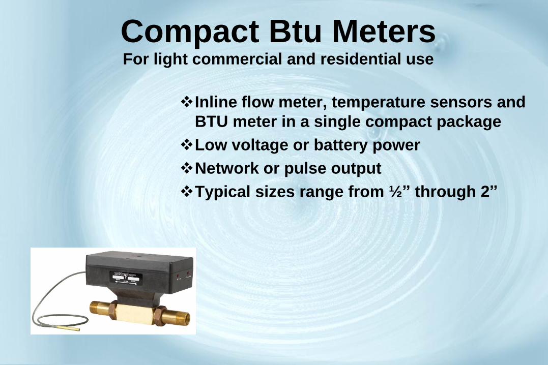
Inline flow meter, temperature sensors and
BTU meter in a single compact package
Low voltage or battery power
Network or pulse output
Typical sizes range from ½” through 2”
Compact Btu Meters For light commercial and residential use

Temperature Sensors for
Btu Measurement • Should be calibrated and characterized
over an application specific temperature range.
• Consider using a signal conditioner (transmitter) to provide current based output signal for stability over long wire runs vs. trying to control lead lengths.
• Consider the total differential temperature accuracy (including A/D conversion and transmitter error) relative to the actual delta-T to determine if the error (uncertainty) is acceptable.
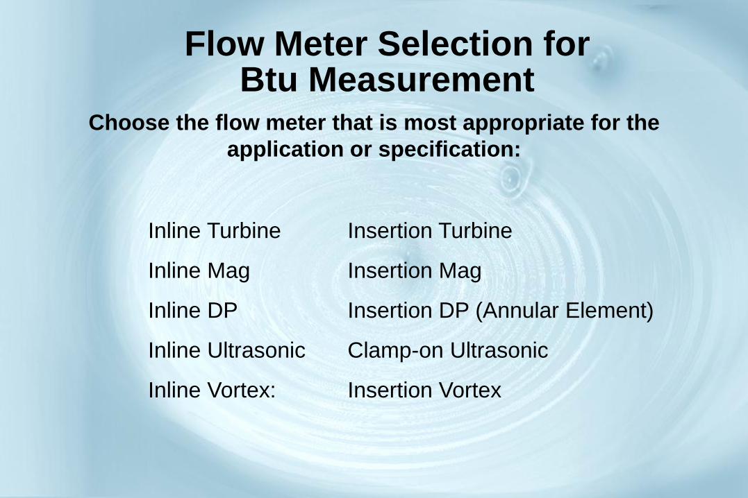
Flow Meter Selection for Btu Measurement
Inline Turbine Insertion Turbine
Inline Mag Insertion Mag
Inline DP Insertion DP (Annular Element)
Inline Ultrasonic Clamp-on Ultrasonic
Inline Vortex: Insertion Vortex
Choose the flow meter that is most appropriate for the
application or specification:

Hot Tap Installation Detail for Thermowell in Welded Pipe

Output Signal Options for BTU Meters:
•Pulse for Energy Total
•Analog (4-20 mA)for Instantaneous Load, GPM, Temps
•Serial Network Communication (LAN)
Open Communication protocols:
BACnet® (MS/TP & IP)
Modbus RTU (RS-485 & TCP/IP)
LONWORKS® (FTTP)
Industrial: Profibus & HART
(Proprietary ?)
Benefits of Btu Meters with Serial
Network Communications
• Improved data accuracy
• All flow, temperature, and energy data available with a single network connection
• Reduces the need for additional controllers by eliminating the hard analog input points typically required for the BTU calculation.
• Reduced installation costs for wire and conduit
• Seamless Totalization Values throughout Network
Important Considerations for a
Btu Measurement System • System & Component Traceability
• Calibrated & matched temperature sensors with clearly defined differential error
• Standard Building Control Network communications protocol
• Single source for all system components and factory calibration of the entire system
• Serviceability & Re-calibration

Flow Meters
Measurement & Selection
Flow Measurement A. Water
B. Steam
C. Gas
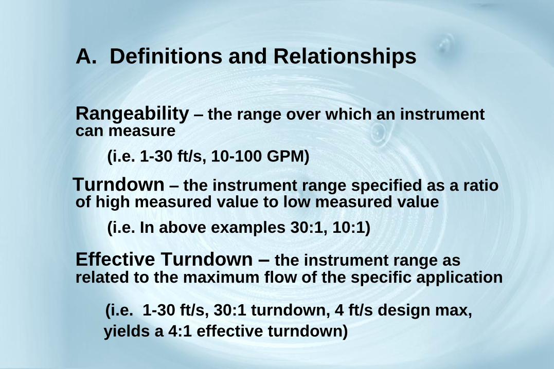
A. Definitions and Relationships
Rangeability – the range over which an instrument can measure
(i.e. 1-30 ft/s, 10-100 GPM)
Turndown – the instrument range specified as a ratio of high measured value to low measured value
(i.e. In above examples 30:1, 10:1)
Effective Turndown – the instrument range as related to the maximum flow of the specific application
(i.e. 1-30 ft/s, 30:1 turndown, 4 ft/s design max,
yields a 4:1 effective turndown)

A. Definitions and Relationships
Accuracy – The ability of an instrument to make the
measurement as referenced to a standard
Repeatability – The deviation of multiple
measurements of the same quantity under the
same conditions. Not a measure of absolute
accuracy.
Linearity – The departure of the calibration curve from
a straight line. Not a measure of absolute accuracy.
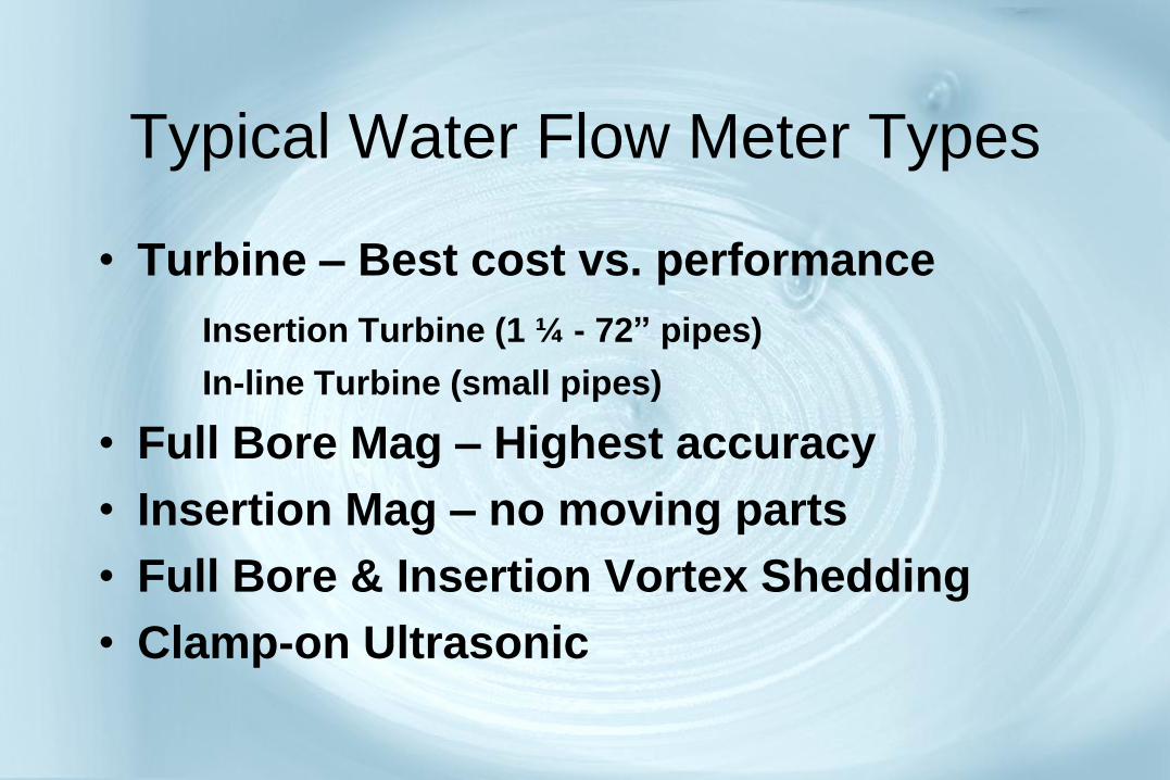
Typical Water Flow Meter Types
• Turbine – Best cost vs. performance
Insertion Turbine (1 ¼ - 72” pipes)
In-line Turbine (small pipes)
• Full Bore Mag – Highest accuracy
• Insertion Mag – no moving parts
• Full Bore & Insertion Vortex Shedding
• Clamp-on Ultrasonic
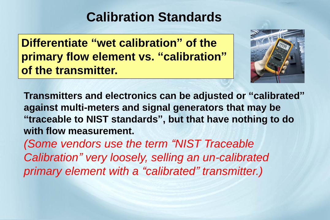
Calibration Standards
Differentiate “wet calibration” of the
primary flow element vs. “calibration”
of the transmitter.
Transmitters and electronics can be adjusted or “calibrated”
against multi-meters and signal generators that may be
“traceable to NIST standards”, but that have nothing to do
with flow measurement.
(Some vendors use the term “NIST Traceable
Calibration” very loosely, selling an un-calibrated
primary element with a “calibrated” transmitter.)
Calibration
Questions to ask:
Is every meter individually wet-calibrated?
How is the meter calibrated?
What is the calibration standard?
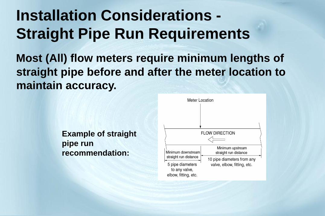
Installation Considerations -
Straight Pipe Run Requirements
Most (All) flow meters require minimum lengths of
straight pipe before and after the meter location to
maintain accuracy.
Example of straight
pipe run
recommendation:

Velocity Profile of Water in Pipes
• Velocity profile is distorted by pipe
obstructions and direction changes.
• Friction from the pipe wall “conditions” the
velocity profile, eventually flattening the profile. (based on velocity and viscosity typically found in
HVAC applications)
• LAMINAR Flow is needed

Straight Pipe Run Requirements
Actual upstream/downstream dimensions typically
depend on type of pipe obstruction & meter type.
Consider both “supply” and “return” for available
pipe run.

Straight Run Requirements Industry Standard (Reality)

General Piping Requirements
Basic Flow Meter Configurations:
Basic Configurations (measuring what):
• Full Bore/Inline (volume or velocity)
• Insertion (velocity)
• Clamp-on (velocity)
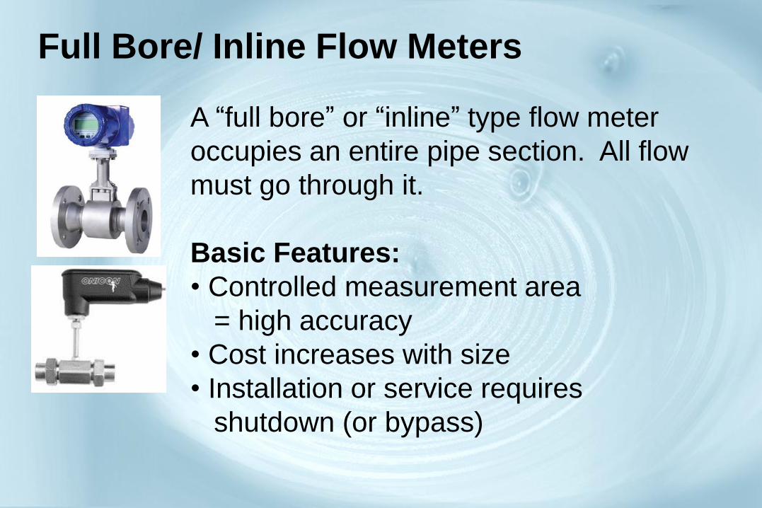
Full Bore/ Inline Flow Meters
A “full bore” or “inline” type flow meter
occupies an entire pipe section. All flow
must go through it.
Basic Features:
• Controlled measurement area
= high accuracy
• Cost increases with size
• Installation or service requires
shutdown (or bypass)
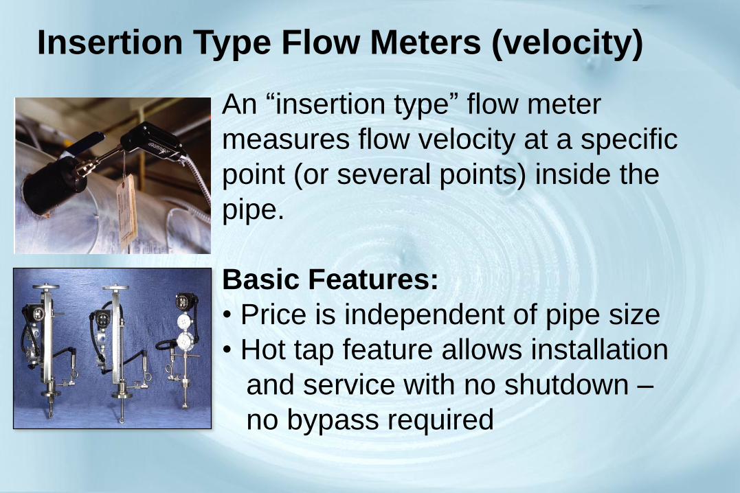
Insertion Type Flow Meters (velocity)
An “insertion type” flow meter
measures flow velocity at a specific
point (or several points) inside the
pipe.
Basic Features:
• Price is independent of pipe size
• Hot tap feature allows installation
and service with no shutdown –
no bypass required
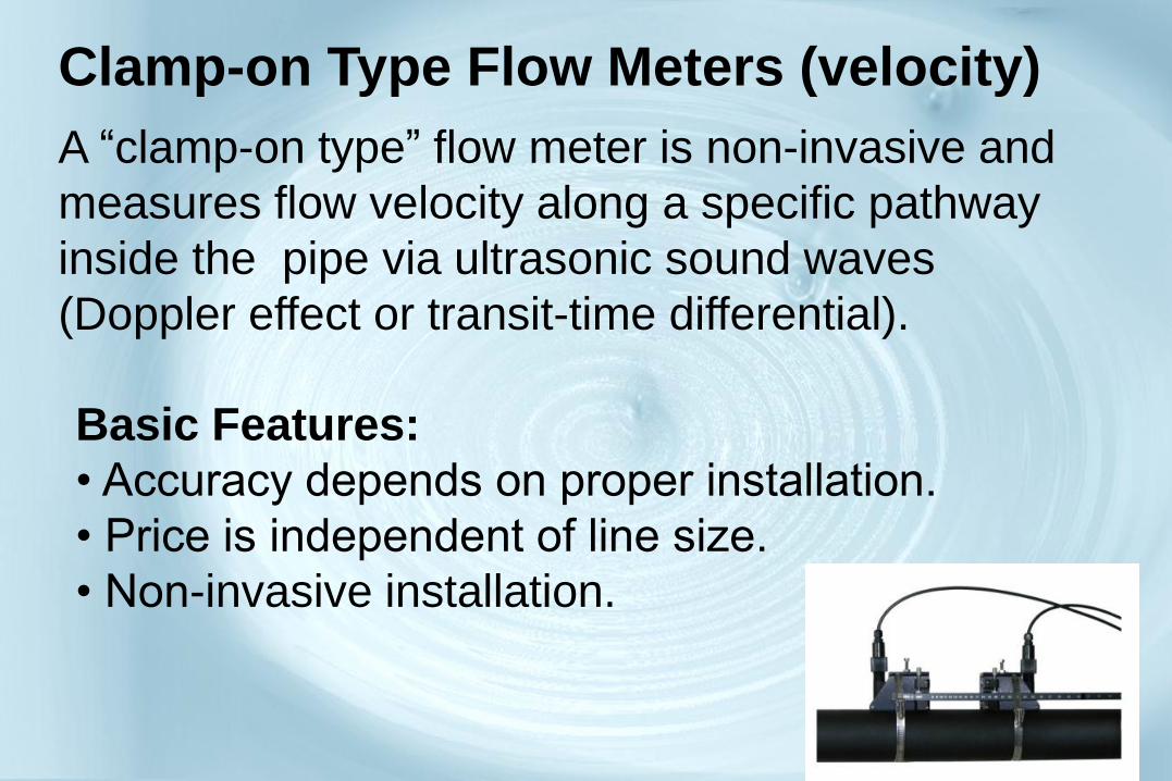
Clamp-on Type Flow Meters (velocity)
Basic Features:
• Accuracy depends on proper installation.
• Price is independent of line size.
• Non-invasive installation.
A “clamp-on type” flow meter is non-invasive and
measures flow velocity along a specific pathway
inside the pipe via ultrasonic sound waves
(Doppler effect or transit-time differential).

Turbine Flow Meter Principle of Operation
FLOW →
Water strikes the blades of the turbine causing it to spin. The speed of
the turbine is directly proportional to the velocity of the water.
Turbine technology is inherently linear and repeatable, and is even
used as a calibration standard
in many applications.
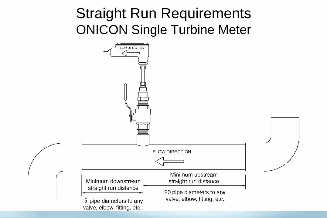
Straight Run Requirements ONICON Single Turbine Meter
5
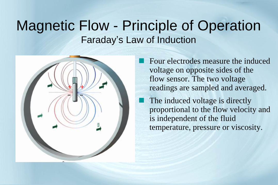
Magnetic Flow - Principle of Operation Faraday’s Law of Induction
Four electrodes measure the induced voltage on opposite sides of the flow sensor. The two voltage readings are sampled and averaged.
The induced voltage is directly proportional to the flow velocity and is independent of the fluid temperature, pressure or viscosity.
+
-
+
-

In-Line Mag Meter Principle of Operation
Accurate measurement depends on the generation of a uniform magnetic field.
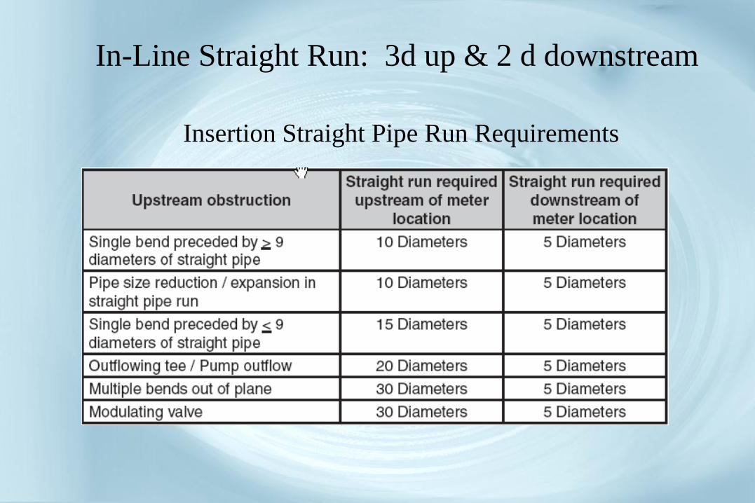
In-Line Straight Run: 3d up & 2 d downstream
Insertion Straight Pipe Run Requirements
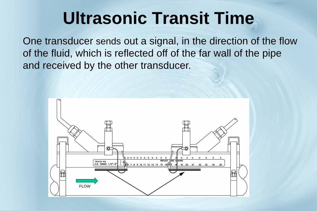
Ultrasonic Transit Time
One transducer sends out a signal, in the direction of the flow
of the fluid, which is reflected off of the far wall of the pipe
and received by the other transducer.
FLOW

Ultrasonic Transit Time The process is then repeated in the opposite direction
against the flow.
FLOW
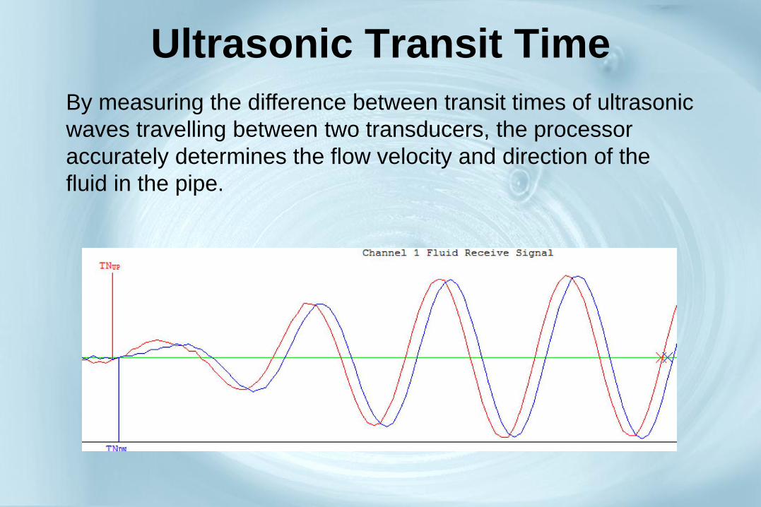
Ultrasonic Transit Time
By measuring the difference between transit times of ultrasonic
waves travelling between two transducers, the processor
accurately determines the flow velocity and direction of the
fluid in the pipe.
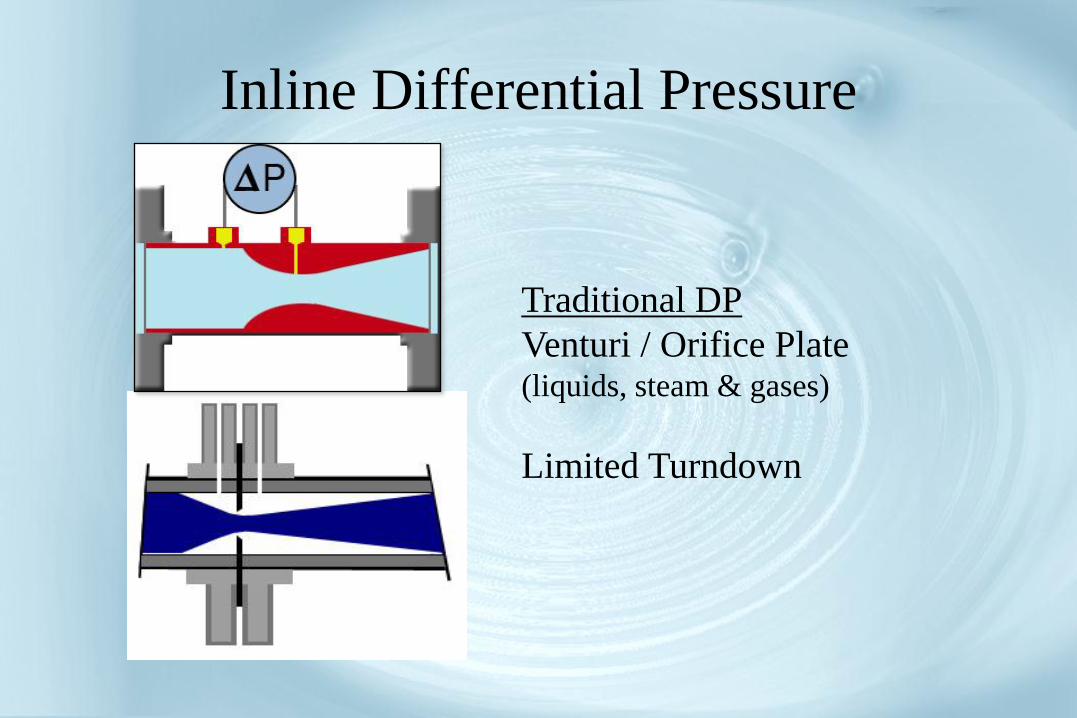
Inline Differential Pressure
Traditional DP
Venturi / Orifice Plate (liquids, steam & gases)
Limited Turndown

Principle of Vortex Shedding
When any liquid, gas or vapor in motion hits a
solid body in its path, it flows around it, shedding
vortices alternately on either side of the body.
The frequency of the vortices is directly proportional
to the velocity of the flow.
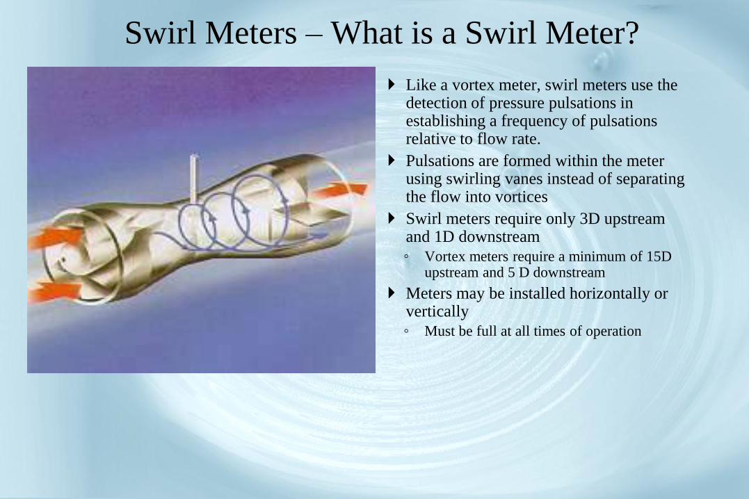
Swirl Meters – What is a Swirl Meter?
Like a vortex meter, swirl meters use the detection of pressure pulsations in establishing a frequency of pulsations relative to flow rate.
Pulsations are formed within the meter using swirling vanes instead of separating the flow into vortices
Swirl meters require only 3D upstream and 1D downstream
◦ Vortex meters require a minimum of 15D upstream and 5 D downstream
Meters may be installed horizontally or vertically
◦ Must be full at all times of operation
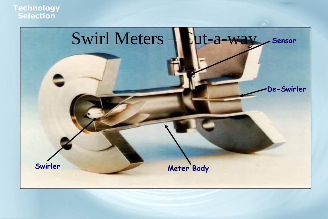
Swirl Meters – Cut-a-way Sensor
De-Swirler
Swirler Meter Body
Technology Selection
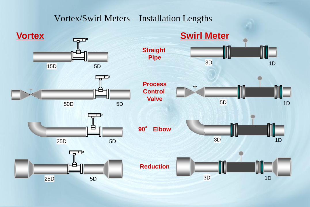
Swirl Meter Vortex
Vortex/Swirl Meters – Installation Lengths
Reduction
90° Elbow
3D 1D
Process
Control
Valve 50D 5D 5D 1D
3D 1D
Straight
Pipe
15D 5D
3D 1D 25D 5D
25D 5D

Traditional Method:
Flow, Temp and Pressure
Pressure Temp
Mass Flow
Computer Flow
Recent Trend: Integral
Density Compensation
o Less complex to install
o High accuracy easily
achieved
Mass Flow Measurement of Saturated Steam
o More complex to install
o Determining mass flow
uncertainty is more
involved
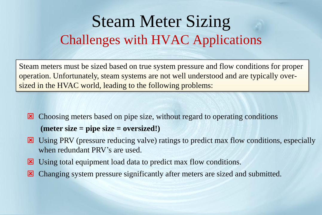
Steam Meter Sizing Challenges with HVAC Applications
Steam meters must be sized based on true system pressure and flow conditions for proper
operation. Unfortunately, steam systems are not well understood and are typically over-
sized in the HVAC world, leading to the following problems:
Choosing meters based on pipe size, without regard to operating conditions
(meter size = pipe size = oversized!)
Using PRV (pressure reducing valve) ratings to predict max flow conditions, especially
when redundant PRV’s are used.
Using total equipment load data to predict max flow conditions.
Changing system pressure significantly after meters are sized and submitted.
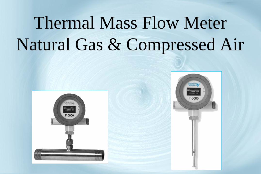
Thermal Mass Flow Meter
Natural Gas & Compressed Air

Principle of Operation
Each Meter has a pair of
encapsulated platinum sensors that
are in direct contact with the gas.
The reference sensor measures the
ambient gas temperature.
The flow sensor is self-heated.
Thermal mass flow meters directly measure
the mass of the flowing gas by utilizing the
principle of convective heat transfer.

Principle of Operation
As gas flows by the heated flow sensor, our
proprietary sensing circuitry maintains a constant
temperature differential between the two sensors.
The energy (mW) required to maintain this
temperature differential is directly proportional to the
mass flow.
There is no need for additional temperature or
pressure compensation!
Note: Requires 8-15 diameters of straight run –
Applicaiton Dependent
Hydraunic & Gas Utilities Metering
Considerations
•Factory Calibrated BTU Sytem - Traceability
•Temp Sensor Pairing – improved BTU Calc
•Flow Metering Selection – Cost/Application
•Integration with Energy Monitoring System
•Serviceability

Hydraunic & Gas Utilities Metering
Benefits / Results
•Utilities Cost Allocation
•Central Utilities Growth Planning
•Promote Conservation
•Acquire LEED points
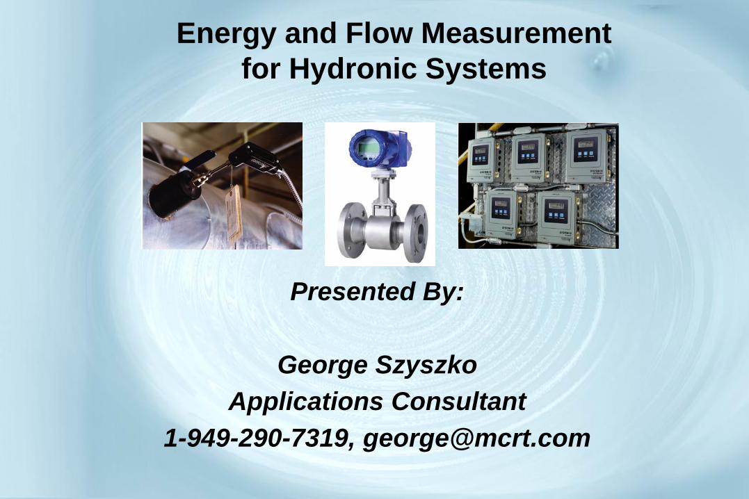
Presented By:
George Szyszko
Applications Consultant
1-949-290-7319, [email protected]
Energy and Flow Measurement
for Hydronic Systems