EnergoProFin - Maritimeexpert Website · Rev – First issue . ... any form or by any means,...
45
EnergoProFin Instruction Manual Order number: SNL/15023.M5-M8 Document nr: DAAF302908 revision – Copyright Wärtsilä. All rights reserved. Nothing from this publication may be reproduced or disclosed without prior written approval of Wärtsilä. SNL/15023.M5-M8 EnergoProFin Instruction Manual GENERAL Wärtsilä installation no. Vessel IMO Vessel Name Yard Hull SNL/15023.M5-HF11P 9193719 MSC Lana Stocznia Gdynia S.A. 94290 SNL/15023.M6-HF11P 9163207 MSC Nora 94010 SNL/15023.M7-HF11P 9193680 MSC Tia 94289 SNL/15023.M8-HF11P 9163192 MSC Uma 94009 DOCUMENT HISTORY Revision Date Comment – 17 July 2015 First release Wärtsilä Netherlands B.V. P.O. Box 6 5150 BB Drunen The Netherlands Phone +31 416 388 424 Internet http://www.wartsila.com
Transcript of EnergoProFin - Maritimeexpert Website · Rev – First issue . ... any form or by any means,...

EnergoProFin Instruction Manual Order number: SNL/15023.M5-M8 Document nr: DAAF302908 revision –
Copyright Wärtsilä. All rights reserved. Nothing from this publication may be reproduced or disclosed without prior written approval of Wärtsilä.
SNL/15023.M5-M8
EnergoProFin Instruction Manual
GENERAL Wärtsilä installation no. Vessel IMO Vessel Name Yard Hull SNL/15023.M5-HF11P 9193719 MSC Lana Stocznia Gdynia S.A. 94290
SNL/15023.M6-HF11P 9163207 MSC Nora 94010
SNL/15023.M7-HF11P 9193680 MSC Tia 94289
SNL/15023.M8-HF11P 9163192 MSC Uma 94009
DOCUMENT HISTORY Revision Date Comment – 17 July 2015 First release
Wärtsilä Netherlands B.V. P.O. Box 6 5150 BB Drunen The Netherlands Phone +31 416 388 424 Internet http://www.wartsila.com

EnergoProFin Instruction Manual Order number: SNL/15023.M5-M8 Document nr: DAAF302908 revision –
Copyright Wärtsilä. All rights reserved. Nothing from this publication may be reproduced or disclosed without prior written approval of Wärtsilä.
REVISION MANAGEMENT PAGES Rev – First issue

EnergoProFin Instruction Manual Order number: SNL/15023.M5-M8 Document nr: DAAF302908 revision –
Copyright Wärtsilä. All rights reserved. Nothing from this publication may be reproduced or disclosed without prior written approval of Wärtsilä.
PREFACE Wärtsilä herewith presents you the EnergoProFin Instruction Manual.
This instruction manual gives an overview of the EnergoProFin. It contains all relevant information of the installation process, including drawings and parts lists.
In case of any questions, or if further technical assistance or information is needed, please do not hesitate to contact Wärtsilä.
Wärtsilä
Copyright statement
All rights reserved. Nothing from this publication may be reproduced, or transmitted in any form or by any means, electronic or mechanical, including photocopying, recording or any information storage or retrieval system without prior written approval of Wärtsilä.
Also for using one or more parts of this publication in papers, readers and other collected works, contact Wärtsilä.
For additional information about Wärtsilä Corporation, please visit our website at http://www.wartsila.com/services. Service works and products supplied by a company belonging to Wärtsilä Corporation are subject to the applicable Wärtsilä General Terms and Conditions set forth on our website.

EnergoProFin Instruction Manual Order number: SNL/15023.M5-M8 Document nr: DAAF302908 revision –
Copyright Wärtsilä. All rights reserved. Nothing from this publication may be reproduced or disclosed without prior written approval of Wärtsilä.
CONTENTS 1. General
1.1 Introduction to the instructions 1.2 Warranty 1.3 Safety instructions
1.3.1 WARNINGS 1.3.2 CAUTIONS
2. Installation particulars 2.1 Definition 2.2 Deliverables 2.3 Upon delivery
3. Installation overview and description 3.1 Introduction to the EnergoProFin 3.2 Description of geometry
4. Cathodic protection
5. Installation 5.1 Introduction to EnergoProFin positioning 5.2 Mounting the EnergoProFin
5.2.1 Preparations 5.2.2 Handling of the EnergoProFin 5.2.3 Preparing the EnergoProFin 5.2.4 Preparing the propeller 5.2.5 Protecting the propeller and propeller nut with grease 5.2.6 Mounting the EnergoProFin
5.3 Filling the mounting groove with the filler material 5.3.1 Preparations 5.3.2 Preparing the mounting groove 5.3.3 Filling the mounting groove
6. De-installation 6.1 De-installation of the EnergoProFin
6.1.1 Preparations 6.1.2 Removing the filler material 6.1.3 De-mounting the EnergoProFin
7. Storage, Maintenance 7.1 Storage location 7.2 Periodical checks while stored
7.2.1 Every 3 months 7.3 Maintenance
8. Re-use of parts and spare parts ordering 8.1 Spare parts ordering 8.2 Re-usable parts
APPENDIX A – Drawings and parts lists
APPENDIX B – Filler material information
EnergoProFin Instruction Manual Order number: SNL/15023.M5-M8 Document nr: DAAF302908 revision –
Copyright Wärtsilä. All rights reserved. Nothing from this publication may be reproduced or disclosed without prior written approval of Wärtsilä.
1. General
1.1 Introduction to the instructions
Read the preface and all chapters of the instruction manual, the installation drawings and datasheets before starting any action.
If not clearly understood, contact Wärtsilä for an explanation. The equipment must be handled with care by qualified and trained personnel.
Request for a authorised service engineer well in advance.
Furthermore please read chapter 1.3 concerning safety.
Scope of supply Note that the relevant contract specifies the Scope of Supply and is the only valid definition of the items that are supplied by Wärtsilä.
Accessibility Some components have large dimensions and / or need extra space during installation, operation and maintenance.
Transport & storage Several components are heavy and / or have large dimensions, or are to be treated with special care and attention. Adequate transport means must be used during any handling in the ship, at the yard and during transport to / from Wärtsilä. The instructions on the packaging must be observed.
Installation Installation starts after the ship is prepared. There can be large time intervals between installation periods for major system units. Contact the service department timely for assistance schedules.
Commissioning Commissioning starts after installation of the equipment is completed. Contact the service department timely for assistance schedules.
Trials Trials are divided in dock trials (ship afloat, running prime mover) and sea trials (ship at sea). Contact the service department timely for assistance schedules.

EnergoProFin Instruction Manual Order number: SNL/15023.M5-M8 Document nr: DAAF302908 revision –
Copyright Wärtsilä. All rights reserved. Nothing from this publication may be reproduced or disclosed without prior written approval of Wärtsilä.
1.2 Warranty
Warranty conditions are contained in the relevant contract.
Warranty conditions may be rejected when:
The installation details differ from details communicated previously, or installation has been modified without informing Wärtsilä.
The installation has been installed, operated, and maintained not in accordance with Wärtsilä instructions.
The installation has been modified without prior Wärtsilä consent.
The loading conditions differ from conditions agreed upon.
Wärtsilä does not accept any responsibility for complaints or damage caused by vibration problems resulting from the total system.
1.3 Safety instructions
Wärtsilä takes no responsibility for the activities described in this manual.
It is not strictly prescribed in this manual which warning and cautions are applicable. This should be judged for each situation by qualified/ skilled personnel.
Pay attention to the WARNINGS, CAUTIONS and Instructions.
All safety regulations by authorities must be obeyed.

EnergoProFin Instruction Manual Order number: SNL/15023.M5-M8 Document nr: DAAF302908 revision –
Copyright Wärtsilä. All rights reserved. Nothing from this publication may be reproduced or disclosed without prior written approval of Wärtsilä.
1.3.1 WARNINGS
ALWAYS BE CAREFULL WHEN YOU WORK AROUND ROTATING COMPONENTS.
CHECK THE EQUIPMENT FREQUENTLY TO PREVENT POSSIBLE DANGEROUS CONDITIONS.
FOLLOW THE DIRECTIONS IN THE MANUAL.
USE APPROVED HOISTING POINTS AND CERTIFIED LIFTING EQUIPMENT OF ADEQUATE CAPACITY.
MAKE SURE THAT EQUIPMENT CAN NEITHER TILT NOR MOVE DURING LIFTING.
MAKE SURE THERE IS SUFFICIENT SPACE AND THAT WORKERS ARE IN SAFE POSITIONS.
MAKE SURE THAT YOU SHUT OFF THE PRIME MOVERS AND ALL PUMPS, DISCONNECT THE ELECTRIC POWER SUPPLY AND CLOSE ALL RELEVANT VALVES, WHEN YOU WORK ON EQUIPMENT
MAKE SURE THAT THE PRIME MOVER CANNOT BE ACCIDENTALLY STARTED.
PUT WARNING SIGNS IN POSITION.
MAKE SURE THAT NO ONE IS WORKING ON THE EQUIPMENT BEFORE STARTING THE PRIME MOVER.
DO NOT, UNDER ANY CIRCUMSTANCES, START THE PRIME MOVER OR OPERATE EQUIPMENT WHEN A WARNING SIGN IS ATTACHED.
MAKE SURE THAT HIGH PRESSURISED OIL CAN NOT LEAK. PLACE PROTECTIVE GUARDS IN POSITION.
ALWAYS WEAR PROTECTIVE GLASSES AND CLOTHES WHEN YOU WORK ON EQUIPMENT.
OIL PIPES OR HOSES OF INSUFFICIENT STRENGTH CAN BURST UNDER PRESSURE. SEVERE INJURY CAN RESULT.
DO NOT DISCONNECT HYDRAULIC PIPES OR HOSES WHEN PUMPS ARE OPERATING.
MAKE SURE THAT ALL PROTECTIVE GUARDS AND COVERS ARE CORRECTLY INSTALLED.
MAKE SURE THAT ROTATION BY GRAVITY IS NOT POSSIBLE.
MAKE SURE THAT UNCONTROLLED ROTATION OF THE THRUSTER IS NOT POSSIBLE DURING HANDLING OF THE THRUSTER AND DURING LAUNCHING OF THE SHIP.
DO NOT MIX METRIC FASTENERS WITH OTHER (STANDARD) FASTENERS. MISMATCHED OR INCORRECT FASTENERS WILL CAUSE DAMAGE TO OR MALFUNCTION OF EQUIPMENT OR CAN RESULT IN INJURY.

EnergoProFin Instruction Manual Order number: SNL/15023.M5-M8 Document nr: DAAF302908 revision –
Copyright Wärtsilä. All rights reserved. Nothing from this publication may be reproduced or disclosed without prior written approval of Wärtsilä.
DISCONNECT THE MAINS AND BACK-UP POWER SUPPLIES WHEN YOU WORK ON THE REMOTE CONTROL AND PUT WARNING SIGNS IN POSITION. THE REMOTE CONTROL SYSTEM IS ALWAYS UNDER LIVE VOLTAGE.
DISCONNECT INTERFACE CIRCUITS THAT ARE UNDER VOLTAGE FROM OTHER POWER SUPPLIES.
1.3.2 CAUTIONS
ALWAYS ATTACH LIFTING EQUIPMENT TO THE LIFTING POINTS OR TO PLACES INDICATED ON THE (TRANSPORT) DRAWINGS. USE SHACKLES OR SLINGS.
DO NOT ATTACH LIFTING EQUIPMENT TO MACHINED SURFACES, SHAFT ENDS, PIPING WORK OR OTHER EXTERNALLY MOUNTED EQUIPMENT.
MAKE SURE THAT YOU PLACE SUFFICIENTLY SIZED OIL OR FLUID CATCH TANK(S).
ALWAYS COLLECT AND REMOVED SPILLED OIL OR FLUID FROM (DIS)-ASSEMBLY PROCEDURES.
MAKE SURE THAT YOU DRAIN SYSTEM OIL OR FLUID BEFORE EQUIPMENT DISASSEMBLY.
MAKE SURE THERE IS NO DIRT OR FOREIGN MATERIALS IN THE HYDRAULIC OR CIRCULATION SYSTEMS. THIS CAN CAUSE EXTENSIVE DAMAGE TO EQUIPMENT.
DO NOT USE ALKALINE OR CHEMICAL DETERGENTS TO CLEAN, RUBBER, SYNTHETIC OR PAINTED COMPONENTS. THEY CAN CAUSE DAMAGE TO EQUIPMENT. WIPE WITH A DRY CLOTH ONLY.
IF PRESSURE PUMPS ARE INSTALLED IN PARALLEL, MAKE SURE THE HYDRAULIC SYSTEM IS DESIGNED FOR SUCH PURPOSE. CHECK THE HYDRAULIC SYSTEM FIRST.
SIMULTANEOUSLY RUNNING OF PUMPS CAN CAUSE SERIOUS DAMAGE TO EQUIPMENT.
ALWAYS EARTH SCREENED CABLES EXCLUSIVELY AT CABINET SIDE, NEVER AT PANEL NOR COMPONENT SIDE.
ELECTRIC WELDING INTRODUCES SPIKES. ALWAYS DISCONNECT THE MAINS AND BACK-UP POWER SUPPLIES TO THE ELECTRONIC CABINET OR TO COMPONENTS CLOSE TO THE WELDING AREA.
DO NOT USE CONTROL PANELS OR ELECTRICAL CABINETS AS AN EARTH POINT WHEN WELDING, THIS CAN CAUSE DAMAGE TO ELECTRCAL COMPONENTS.
ALWAYS CONNECT TO A GOOD EARTH POINT WHEN WELDING, CLOSE TO THE WELDING AREA TO AVOID DAMAGE TO EQUIPMENT SURFACES.
WHEN WELDING PROTECT THE SURROUNDING FROM WELDING SPATTERS.
EnergoProFin Instruction Manual Order number: SNL/15023.M5-M8 Document nr: DAAF302908 revision –
Copyright Wärtsilä. All rights reserved. Nothing from this publication may be reproduced or disclosed without prior written approval of Wärtsilä.
2. Installation particulars
2.1 Definition
Wärtsilä installation nr. Installation and vessel particulars
See the Classification data sheet in Appendix A.
Arrangement drawing See the Propeller arrangement EnergoProFin in Appendix A.
Designation EnergoProFin
2.2 Deliverables
The delivery consists of:
- EnergoProFin assembly
o EnergoProFin
o Studs, Nuts and Locking rings
o O-ring and/or gasket
o Fill/vent plug and sealing ring
o Plugs for the hoisting eye positions
o Epoxy filling material
- Hoisting and transport parts
o Hoisting eye aft
o Hoisting eye fwd
- A digital copy of this manual
2.3 Upon delivery
Upon arrival of materials it is recommended to check if everything listed on the bill of materials is present.
Please consider the bills of material which can be found in Appendix A.
- EnergoProFin assembly
- Hoisting and transport parts

EnergoProFin Instruction Manual Order number: SNL/15023.M5-M8 Document nr: DAAF302908 revision –
Copyright Wärtsilä. All rights reserved. Nothing from this publication may be reproduced or disclosed without prior written approval of Wärtsilä.
3. Installation overview and description
3.1 Introduction to the EnergoProFin
The EnergoProFin is an energy saving device that consists of a modified propeller hub cap with fins. It improves propulsive efficiency by weakening the hub vortex (also called propeller ‘swirl’) and recovering kinetic energy from the rotating flow aft of the propeller blades. Weakening the hub vortex decreases propeller resistance and manifests itself as increased thrust. The deflection of the flow aft of the propeller by the fins reduces the propeller torque.
In addition to the improved propulsive efficiency, the EnergoProFin can also be applied to reduce propeller-induced noise and vibration levels.
The EnergoProFin is designed as an integral part of the propeller. The installation of the EnergoProFin will not affect the manoeuvrability of the vessel.
3.2 Description of geometry
The EnergoProFin is a single part consisting of a hub with fins, made from a Nickel-Aluminium-Bronze comparable to that of most propellers. The number of fins is equal to the number of propeller blades. The EnergoProFin is mounted onto the propeller hub.
The propeller hub spigot is used for concentric alignment. Mounting to the propeller hub is done by studs and nuts. Locking rings are used to lock the nuts and to reduce the surface pressure at the flange.
Sealing is done with an o-ring, either positioned on the propeller hub or EnergoProFin. In case the o-ring sealing surface is damaged, a gasket is provided.
Hoisting eyes are provided for handling the EnergoProFin. The hoisting eye holes are filled with plugs to preserve the thread during operation. Fill/vent plugs are present (2x).
The mounting groove is filled with a special epoxy filler material in order not to disturb the water flow.
fin
hub
aft hoisting point
mounting hole
fwd hoisting point
o-ring/gasket * spigot *
fill/vent plug *
mounting groove mounting flange
* not visible
drawn for a clockwise rotating propeller

EnergoProFin Instruction Manual Order number: SNL/15023.M5-M8 Document nr: DAAF302908 revision –
Copyright Wärtsilä. All rights reserved. Nothing from this publication may be reproduced or disclosed without prior written approval of Wärtsilä.
4. Cathodic protection
Note: This chapter is provided for reference only. Preventing galvanic corrosion to occur and design of the cathodic protection is not Wärtsilä responsibility.
The presence of the EnergoProFin is likely to affect the amount of cathodic protection needed. The material of the EnergoProFin is close or equal to the galvanic series of the propeller (the EnergoProFin has a current density of Is = 0,7 A/m²).
Galvanic action is induced by the presence of two different metals, grounded to each other, making contact to the seawater acting as an electrolyte. For a propulsion installation, these metals are for instance the propeller and the steel construction surrounding the propeller. The galvanic action causes galvanic corrosion of steel parts. In order to prevent this galvanic corrosion of steel parts, vessels require cathodic protection.
In designing a cathodic protection system, one has to consider the entire vessel. Commonly, a combination of an impressed current cathodic protection system (ICCP) is applied, together with sacrificial anodes. As most impressed current systems will insufficiently protect the aft of the vessel around the rudder and propeller, sacrificial anodes are used in this area.
The increased area of the noble materials of the propeller with EnergoProFin results in an increased galvanic action, where the propeller acts as cathode and to the ship’s hull as anode.
As the galvanic action will require more current, the current capacity of the cathodic protection system is to be increased to achieve sufficient protection. Furthermore, in case of protection by sacrificial anodes, the total mass of the anodes is to be increased to achieve the same service interval for the anodes.
The amount of additional current and anode mass needed, can be considered directly proportional with the increased propeller surface area due to fitting the EnergoProFin.

EnergoProFin Instruction Manual Order number: SNL/15023.M5-M8 Document nr: DAAF302908 revision –
Copyright Wärtsilä. All rights reserved. Nothing from this publication may be reproduced or disclosed without prior written approval of Wärtsilä.
5. Installation
5.1 Introduction to EnergoProFin positioning
The circumferential position of the EnergoProFin fins with reference to the propeller blades is important for maximizing propulsive efficiency gain.
On the EnergoProFin there is a marking present (see picture):
“TE” The circumferential point where the trailing edge of a propeller blade enters the propeller hub.
In some cases also a “TOP” marking is present on the EnergoProFin and/or propeller. Do NOT use these “TOP” markings for alignment.
drawn for a clockwise rotating propeller
Do NOT use for alignment
Align “TE”
EnergoProFin Instruction Manual Order number: SNL/15023.M5-M8 Document nr: DAAF302908 revision –
Copyright Wärtsilä. All rights reserved. Nothing from this publication may be reproduced or disclosed without prior written approval of Wärtsilä.
5.2 Mounting the EnergoProFin
5.2.1 Preparations
Required condition - Propeller in final position on the shaft. - Propeller nut in position. - Propeller hub interface flange cleaned and degreased - Propeller hub thread holes cleaned and degreased. - Propeller accessible.
Tools and equipment needed - Supplied hoisting eyes are to be used. - Certified lifting equipment and shackles. - Torque wrenches. - Pump and connection material for grease.
Consumables (not supplied) - Cleaner/degreaser (for instance Loctite 7063 Super Clean). - Grease for the o-ring: Molykote 111. - Adhesive/studlock for stainless steel fasteners:
Loctite 2701 (for M20 or smaller), or Loctite 275 (above M20). See Appendix A, Propeller arrangement EnergoProFin for boltsize.
- Thread lubricant, for instance Nord-Lock GTP600, Molykote 1000 or equivalent. - Grease for protecting the propeller shaft and propeller nut or filling the EnergoProFin.
For instance tallow grease or Shell Gadus S2 A320 2 or equivalent (previous Shell Rhodina EP (LF) 2).
- Other items not specifically mentioned.
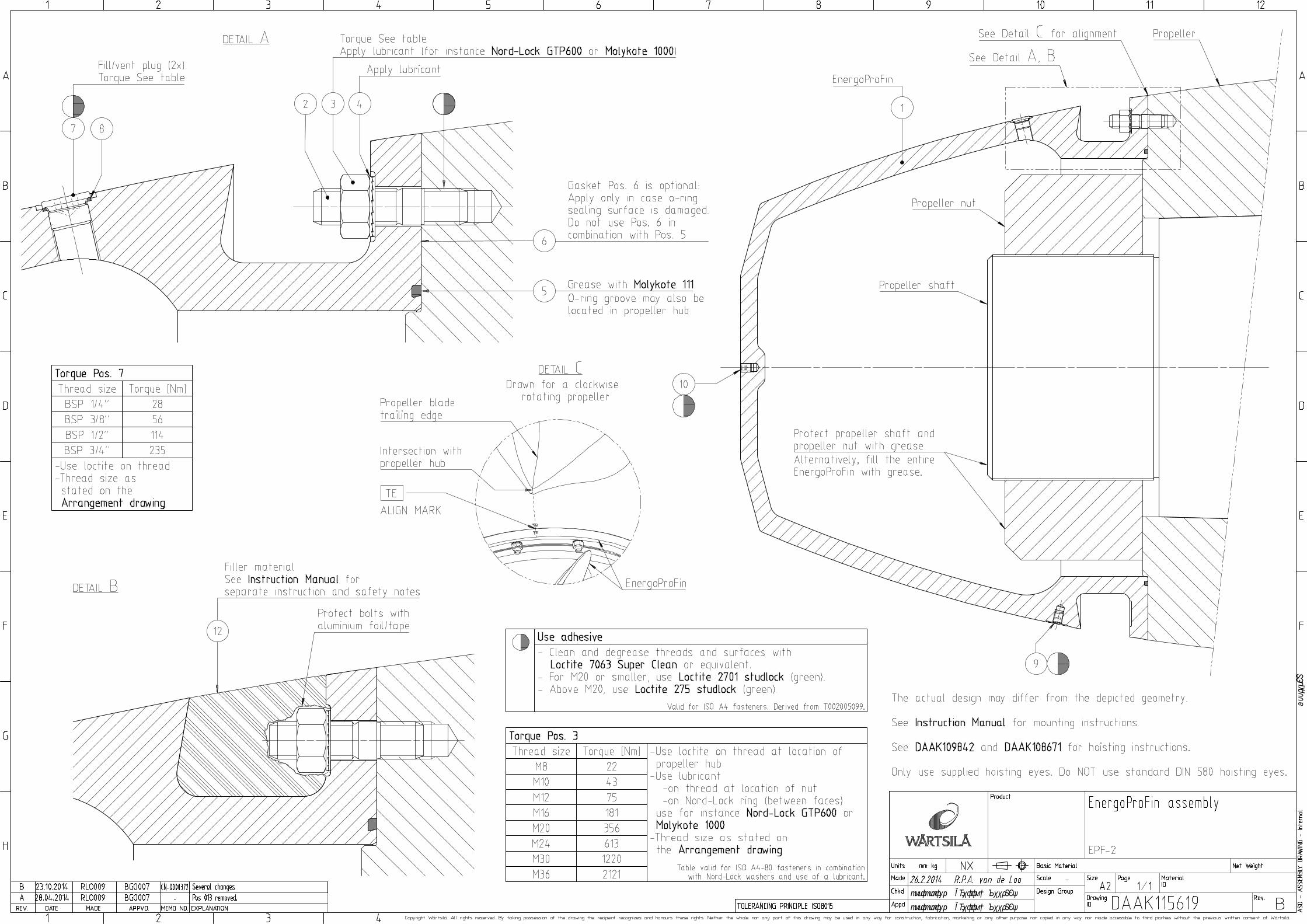
Documents Documents included in Appendix A: - DAAK299066 Propeller arrangement EnergoProFin - DAAK115619 EnergoProFin assembly and partslist - DAAK109842 Hoisting and transport parts EnergoProFin and partslist - DAAK108671 EnergoProFin hoisting instructions
5.2.2 Handling of the EnergoProFin
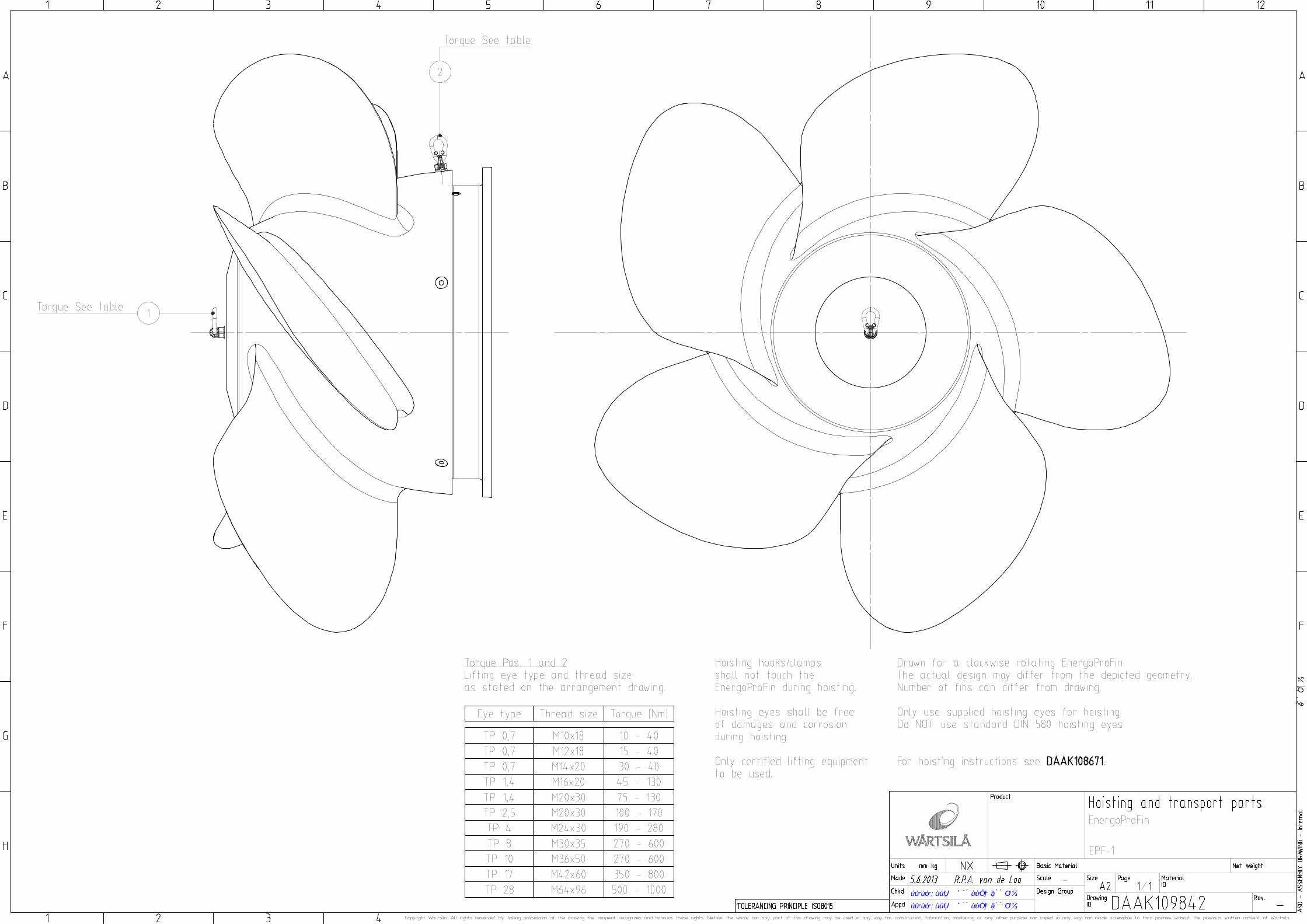
1. Prepare the EnergoProFin for hoisting according to:
DAAK109842 - Hoisting and transport parts EnergoProFin DAAK108671 - EnergoProFin hoisting instructions
Determine hoisting sequence.
Only hoist the EnergoProFin in positions as indicated on DAAK108671. Hoisting hooks/clamps shall not touch the EnergoProFin during hoisting.
Use only the supplied hoisting eyes. Do NOT use standard DIN 580 hoisting eyes. Hoisting eyes shall be free of damages and corrosion during hoisting.
Mount the supplied hoisting eyes on the EnergoProFin. Tighten the hoisting eyes to the required torque.
The required torque is indicated on the Propeller arrangement EnergoProFin and DAAK109842 - Hoisting and transport parts EnergoProFin.
For lifting, only certified lifting equipment is to be used.

EnergoProFin Instruction Manual Order number: SNL/15023.M5-M8 Document nr: DAAF302908 revision –
Copyright Wärtsilä. All rights reserved. Nothing from this publication may be reproduced or disclosed without prior written approval of Wärtsilä.
5.2.3 Preparing the EnergoProFin
2. Clean and degrease the EnergoProFin flange.
3. Inspect for damages.
5.2.4 Preparing the propeller
4. Make sure the propeller is in mounted position (pushed-up) according to the manufacturer’s instructions and the propeller (hydraulic) nut is secured.
5. Clean and degrease the propeller flange, propeller shaft and propeller nut.
6. Mount the studs (Pos. 2) with the smaller length into the propeller flange.
Use Loctite on the thread:
- For M20 or smaller, use Loctite 2701 studlock (green).
- Above M20, use Loctite 275 studlock (green).
The bolt size is indicated on the Propeller arrangement EnergoProFin.
Tightening the studs by hand.
5.2.5 Protecting the propeller and propeller nut with grease
7. The propeller nut and propeller shaft are to be protected with grease. The grease prevents corrosion to the steel parts in case water enters the hub.
For instance tallow grease or Shell Gadus S2 A320 2 or equivalent (previous Shell Rhodina EP (LF) 2) can be used.
Apply grease amply on the propeller shaft and propeller nut.
8. Alternatively, the entire EnergoProFin can be filled with grease.
a. This can be done upfront, before mounting the EnergoProFin. In this case mount the plugs upfront (see step 9).
b. It can also be done after mounting the EnergoProFin by using the plug connections. Use a pump for filling. Use one plug for de-aeration.
The internal volume of the EnergoProFin can be found on the propeller arrangement, in order to determine the amount of grease needed. The volume given is only the volume of the EnergoProFin, so the volume of the propeller spigot, propeller shaft and propeller nut has to be subtracted from this.
One can choose to reduce the amount of grease needed by filling the EnergoProFin partly with expanded PU polyurethane (foam), however this is excluded from the EnergoProFin delivery.
9. Mount the plugs (Pos. 7) and sealing rings (Pos. 8).
Use Loctite 275 studlock (green) on the thread for securing the plug.
Tighten the plugs to the required torque. The required torque is indicated on the Propeller arrangement EnergoProFin
and on the EnergoProFin assembly drawing.

EnergoProFin Instruction Manual Order number: SNL/15023.M5-M8 Document nr: DAAF302908 revision –
Copyright Wärtsilä. All rights reserved. Nothing from this publication may be reproduced or disclosed without prior written approval of Wärtsilä.
5.2.6 Mounting the EnergoProFin
10. Determine which EnergoProFin is to be mounted on which propeller. A clockwise propeller needs an EnergoProFin with a clockwise-rotating fin orientation. The fins should be positioned in the same direction as the propeller blades.
11. Determine the circumferential position of the trailing edge on the propeller hub aft.
Permanently mark the position on the propeller with “TE”.
See also chapter 5.1.
12. Hoist the EnergoProFin and bring it in the vicinity of the propeller. Wait before shifting the EnergoProFin over the propeller shaft, as the O-ring or gasket still needs to be mounted.
13. Clean and degrease the EnergoProFin flange.
14. Inspect the counterpart flange sealing surface of the o-ring groove. In case of damages in the flange, a gasket (Pos. 6) can be used instead of the o-ring (Pos. 5). The O-ring however, is the preferred sealing solution. Do NOT use both.
Use Molykote 111 to grease the o-ring (Pos. 5). Place the o-ring in the o-ring groove (the O-ring groove can be located either in the propeller hub or in the EnergoProFin).
15. Position the EnergoProFin onto the propeller hub towards the final position. Align the “TE” marking on the propeller to the “TE” mark of the EnergoProFin. (Do NOT use the “TOP” mark, see chapter 5.1). Align towards a best practice possible, depending the position of the boltholes. Care not to damage the stud threads.
16. Place the locking rings (Pos. 4) onto the studs and lubricate both with the thread lubricant (for instance Nord-Lock GTP600, Molykote 1000 or equivalent).
The pre-assembled washers are supplied in pairs, cam (wedged) face to cam face:
17. Place the nuts (Pos. 3) and tighten them to the required torque with the torque wrench.
The required torque is indicated on the Propeller arrangement EnergoProFin and on the EnergoProFin assembly drawing.
Tighten in a crosswise pattern.
18. Remove the hoisting eyes from the EnergoProFin and replace them with the plugs (set screws, Pos. 9, 10).
Use Loctite 275 studlock (green) on the thread for securing the plug.

EnergoProFin Instruction Manual Order number: SNL/15023.M5-M8 Document nr: DAAF302908 revision –
Copyright Wärtsilä. All rights reserved. Nothing from this publication may be reproduced or disclosed without prior written approval of Wärtsilä.
5.3 Filling the mounting groove with the filler material
5.3.1 Preparations
Required condition - EnergoProFin mounted on the propeller according to chapter 5.2.
Tools and equipment needed - Equipment according to instructions of the filler material, see Appendix B.
Consumables not supplied - Cleaner/degreaser. - Aluminium foil or aluminium foil tape. - Masking tape (or use the aluminium foil tape). - Other items not specifically mentioned.
Documents Documents included in Appendix A: - DAAK115619 EnergoProFin assembly and partslist All documents included in Appendix B, containing instructions and health and safety sheets for the filler material.
5.3.2 Preparing the mounting groove
1. Protect the studs, nuts, and locking rings with aluminium foil or aluminium foil tape, to ensure cleanliness during future removal.
2. Apply masking tape on the surrounding surfaces on both sides of the groove. Do not apply mounting tape on the surfaces interfacing the filler material.
5.3.3 Filling the mounting groove
3. Apply the filler material (Pos. 12) according manufacturer’s instructions, see Appendix B. Carefully read the manufacturer’s safety notes (wear gloves etc.). Prepare no large batches of cans, but prepare them one after each other. Note the curing time. It is possible to apply the filler material from 180° position (above head). Apply according best practice and shape outer surface. The surface should be flush with the surrounding surfaces to give a level, even contour and a cosmetically acceptable surface.
4. Smoothening of surface can be performed by a wetted brush.
5. Remove masking tape from surrounding surfaces. Clean and remove spillage.
6. Wait until the filler material is cured / hardened, see manufacturer’s data sheet (Appendix B). This takes approx 2 to 24 hour, depending of the surrounding temperature (2 hours at 30 °C). At low temperatures the use of a heater is advised.

EnergoProFin Instruction Manual Order number: SNL/15023.M5-M8 Document nr: DAAF302908 revision –
Copyright Wärtsilä. All rights reserved. Nothing from this publication may be reproduced or disclosed without prior written approval of Wärtsilä.
During curing, prevent the material to protrude by keeping it in shape with a wetted brush.
7. If necessary, grind spillage of filler material according manufacturer’s instruction, see appendix B. Please note grinding of the filler material is difficult. Carefully read the manufacturer’s safety notes (Appendix B).
EnergoProFin Instruction Manual Order number: SNL/15023.M5-M8 Document nr: DAAF302908 revision –
Copyright Wärtsilä. All rights reserved. Nothing from this publication may be reproduced or disclosed without prior written approval of Wärtsilä.
6. De-installation
6.1 De-installation of the EnergoProFin
6.1.1 Preparations
Required condition - EnergoProFin is mounted on the propeller. - EnergoProFin is accessible.
Tools and equipment - Supplied hoisting eyes are to be used. - Certified lifting equipment. - Drill. - Chisel.
Documents Documents included in Appendix A: - DAAK115619 EnergoProFin assembly and partslist All documents included in Appendix B, containing instructions and health and safety sheets for the filler material.
6.1.2 Removing the filler material
1. Remove all filler material by chopping or high water pressure.
2. Remove the aluminium foil and foam.
6.1.3 De-mounting the EnergoProFin
3. In case the hub was filled with grease, use the fill plugs (Pos. 7, 8) to empty the grease (i.e. use pressurized air).
4. Remove the thread plugs located at the position of the hoisting eyes (Pos. 9, 10). Mount the hoisting eyes and prepare lifting equipment.
5. Loosen the nuts (Pos. 3). After removing the nuts and the locking rings (Pos. 4), the EnergoProFin is free and can be removed from the propeller.
6. Remove the studs from the propeller.

EnergoProFin Instruction Manual Order number: SNL/15023.M5-M8 Document nr: DAAF302908 revision –
Copyright Wärtsilä. All rights reserved. Nothing from this publication may be reproduced or disclosed without prior written approval of Wärtsilä.
7. Storage, Maintenance
7.1 Storage location
The equipment shall be stored in a dry and ventilated warehouse with a temperature of 10-40 °C. Prevent exposure to direct sunlight.
7.2 Periodical checks while stored
7.2.1 Every 3 months
Check components for corrosion.
7.3 Maintenance
To maintain the increased propulsive efficiency benefits of the EnergoProFin, it is advised to regularly clean the EnergoProFin outer surfaces by polishing. The cleaning is optional and the cleaning interval depends on the amount of marine growth. It is suggested to perform the polishing together with the propeller polishing/maintenance.

EnergoProFin Instruction Manual Order number: SNL/15023.M5-M8 Document nr: DAAF302908 revision –
Copyright Wärtsilä. All rights reserved. Nothing from this publication may be reproduced or disclosed without prior written approval of Wärtsilä.
8. Re-use of parts and spare parts ordering
8.1 Spare parts ordering
For spare parts ordering, provide the following data:
- Installation number
- Assembly drawing number and title.
- Position number on the assembly drawing.
- Article number and name on the parts list.
- The required quantity.
- All orders are to be confirmed in writing with an official purchase order number and customer VAT number.
Example
Wärtsilä installation number: SN/Lxxxx.Mx-HFxxP Assembly drawing number: DAAKxxxxxx Assembly drawing title: Propeller assembly Pos no.: 2 Article number: PAAIxxxxxx Article name: Plug Quantity: 3
8.2 Re-usable parts
It is advised to only re-use parts as stated below.
EnergoProFin assembly, see Appendix A - Pos. 1, EnergoProFin
If the outer contour and fins are not damaged, no signs of cavitation erosion are present and no deformation of the fins is observed, the EnergoProFin can be re-used.
- Pos. 2 and up It is advised to replace all the seals, bolts and nuts during overhaul. The items could be severely affected due to (pitting) erosion or marine life.
Hoisting and transport parts, see Appendix A Hoisting eyes can be re-used when they do not have damages, such as corrosion. Drilling template, see Appendix A These parts are not needed for future use and can be disposed of after first time installation.

EnergoProFin Instruction Manual Order number: SNL/15023.M5-M8 Document nr: DAAF302908 revision –
Copyright Wärtsilä. All rights reserved. Nothing from this publication may be reproduced or disclosed without prior written approval of Wärtsilä.
APPENDIX A – Drawings and parts lists
A-1 Data sheet DAAF297900 Classification Data Sheet A-2 Drawing DAAF299066 Propeller Arrangement EnergoProFin A-3 Drawing DAAK115619 EnergoProFin Assembly A-4 List PAAF351886 EnergoProFin Assembly – Bill of Material A-5 List PAAI132545 Coating / Filler material – Bill of Material A-6 Drawing DAAK109842 Hoisting and transport parts A-7 List PAAI123701 Hoisting and transport parts – Bill of Material A-8 Drawing DAAK108671 EnergoProFin hoisting instructions
Doc. nr. DAAF297900
Revision -
Date 6/22/2015
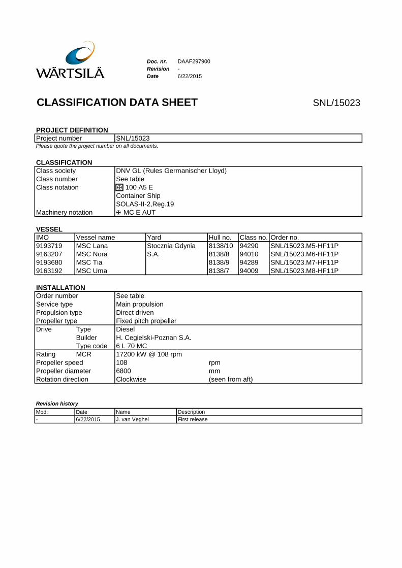
CLASSIFICATION DATA SHEET SNL/15023
PROJECT DEFINITION
Project number SNL/15023Please quote the project number on all documents.
CLASSIFICATION
Class society DNV GL (Rules Germanischer Lloyd)
Class number See table
Class notation 100 A5 E
Container Ship
SOLAS-II-2,Reg.19
Machinery notation MC E AUT
VESSEL
IMO Vessel name Yard Hull no. Class no. Order no.
9193719 MSC Lana 8138/10 94290 SNL/15023.M5-HF11P
9163207 MSC Nora 8138/8 94010 SNL/15023.M6-HF11P
9193680 MSC Tia 8138/9 94289 SNL/15023.M7-HF11P
9163192 MSC Uma 8138/7 94009 SNL/15023.M8-HF11P
INSTALLATION
Order number See table
Service type Main propulsion
Propulsion type Direct driven
Propeller type Fixed pitch propeller
Drive Type Diesel
Builder H. Cegielski-Poznan S.A.
Type code 6 L 70 MC
Rating MCR 17200 kW @ 108 rpm
Propeller speed 108 rpm
Propeller diameter 6800 mm
Rotation direction Clockwise (seen from aft)
Revision history
Mod. Date Name Description
- 6/22/2015 J. van Veghel First release
Stocznia Gdynia
S.A.

bgo007 Goorden22.06.2015bgo007 Goorden22.06.2015
Appr
oved
bgo007 Goorden27.02.2014bgo007 Goorden27.02.2014
Appr
oved

BOM: PAAF351886/-
Seq.
Type:Title:
Drawing:
QuantityItem idItem name
EnergoProFin assembly
EPF-2
Product: PAAF355209/A
DAAF299066-Propeller arrangementDAAK115619-EnergoProFin assembly
Page: 1 of 1
1 1,0PAAF355213/-EnergoProFin2 12,0PAAF311257/-Stud 1,25d3 12,0PAAI116948/-Hexagon nut4 12,0W084820302/BLocking washer5 1,0W007000530/-O-ring6 1,0PAAF355214/-Packing ring7 2,0W006564007/-Hexagon socket collar plug8 2,0M731000290/-Copper sealing ring9 5,0PAAI119760/-Set screw
10 1,0PAAI119760/-Set screw12 6,0PAAI132545/-Coating
Notes: - Sequence numbers not listed have not been used in this product.- The quantities an item numbers shown on the parts list
are believed to be correct, the quantities shown on the drawing are for illustration only.
E N D O F L I S T
7.7.2015

BOM: PAAI132545/-
Seq.
Type:Title:
Drawing:
QuantityItem idItem name
Coating
Product: PAAF355209/A
DAAK116616-Epoxy fillerDAAK116617-InstructionDAAK116618-Instruction
Page: 1 of 1
A 1,0PAAI132524/-CoatingB 1,0PAAI132544/-Coating
Notes: - Sequence numbers not listed have not been used in this product.- The quantities an item numbers shown on the parts list
are believed to be correct, the quantities shown on the drawing are for illustration only.
E N D O F L I S T
7.7.2015
bgo007 Goorden10.06.2013
bgo007 Goorden10.06.2013
App
rove
d

BOM: PAAI123701/-
Seq.
Type:Title:
Drawing:
QuantityItem idItem name
Hoisting and transport parts
Product: PAAF355209/A
DAAK109842-Hoisting and transport partsDAAK108671-Instruction
Page: 1 of 1
1 1,0PAAI123709/-Lifting eye bolt2 2,0PAAI123709/-Lifting eye bolt
Notes: - Sequence numbers not listed have not been used in this product.- The quantities an item numbers shown on the parts list
are believed to be correct, the quantities shown on the drawing are for illustration only.
E N D O F L I S T
7.7.2015

Document Title:
EnergoProFin hoisting instructions
Wärtsilä Netherlands B.V. Department: Propulsion Services Projects Mechanical Document Owner: R.P.A. van de Loo
Date: 12 April 2013 Rev. No: - Document No: DAAK108671
Copyright Wärtsilä. All rights reserved. Nothing from this publication may be reproduced or disclosed without prior written approval of Wärtsilä. Page 1 of 1
EnergoProFin hoisting instructions
- Hoisting should be done comparable to one of the below cases.
- Only supplied hoisting eyes are to be used.
- Only certified lifting equipment is to be used.
A.
B.
C.
D.
E.
F.
G.

EnergoProFin Instruction Manual Order number: SNL/15023.M5-M8 Document nr: DAAF302908 revision –
Copyright Wärtsilä. All rights reserved. Nothing from this publication may be reproduced or disclosed without prior written approval of Wärtsilä.
APPENDIX B – Filler material information
B-1 Data sheet DAAK116616 Product information and user instructions B-2 Data sheet DAAK116617 Safety data sheet, Component A B-3 Data sheet DAAK116618 Safety data sheet, Component B
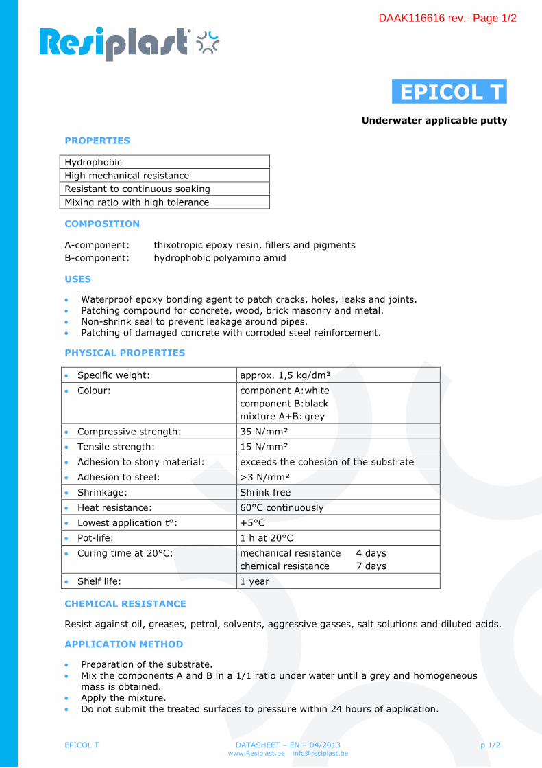
EPICOL T DATASHEET – EN – 04/2013 www.Resiplast.be [email protected]
p 1/2
EPICOL T Underwater applicable putty
PROPERTIES
Hydrophobic
High mechanical resistance
Resistant to continuous soaking
Mixing ratio with high tolerance
COMPOSITION
A-component: thixotropic epoxy resin, fillers and pigments
B-component: hydrophobic polyamino amid
USES
Waterproof epoxy bonding agent to patch cracks, holes, leaks and joints. Patching compound for concrete, wood, brick masonry and metal. Non-shrink seal to prevent leakage around pipes. Patching of damaged concrete with corroded steel reinforcement.
PHYSICAL PROPERTIES
Specific weight: approx. 1,5 kg/dm³
Colour: component A:white
component B:black
mixture A+B: grey
Compressive strength: 35 N/mm²
Tensile strength: 15 N/mm²
Adhesion to stony material: exceeds the cohesion of the substrate
Adhesion to steel: >3 N/mm²
Shrinkage: Shrink free
Heat resistance: 60°C continuously
Lowest application t°: +5°C
Pot-life: 1 h at 20°C
Curing time at 20°C: mechanical resistance 4 days
chemical resistance 7 days
Shelf life: 1 year
CHEMICAL RESISTANCE
Resist against oil, greases, petrol, solvents, aggressive gasses, salt solutions and diluted acids.
APPLICATION METHOD
Preparation of the substrate. Mix the components A and B in a 1/1 ratio under water until a grey and homogeneous
mass is obtained. Apply the mixture. Do not submit the treated surfaces to pressure within 24 hours of application.
DAAK116616 rev.- Page 1/2

EPICOL T DATASHEET – EN – 04/2013 www.Resiplast.be [email protected]
p 2/2
PACKAGING
EPICOL T Comp A Comp B
Set 5 kg: 2,5 kg 2,5 kg
CAUTION
Before application of EPICOL products, refer to safety and handling instructions. EPICOL products have a characteristic odour during application. All food and beverages in
the immediate vicinity of the application area are to be removed. Use rubber gloves and moisten your hands when working with EPICOL T. Avoid contact
with skin. High concentration of vapours can cause irritation of eyes, respiratory system and skin.
Take care of adequate ventilation. EPICOL systems are inflammable during application. Smoking and exposure to naked flames are not permitted.
STORAGE
EPICOL products must be stored away of direct sunlight, in a dry, well-ventilated area between 5 and 35°C.
EPICOL products should be used within a period of 1 year after production date. In case of doubt, contact RESIPLAST N.V. and mention the batch number on the label. Do not empty the products or surplus into drains.
WARRANTY
RESIPLAST N.V. warrants all goods to be free of defects and will replace materials proven to be defective. The information and recommendations herein are believed by RESIPLAST N.V. to be accurate and reliable, based on our present knowledge.
DAAK116616 rev.- Page 2/2

SAFETY DATA SHEET
Revision date: 17/04/2013
Print date: 03/06/2013
1 Identification of the substance/mixture and of the company/undertaking:
1.1 Product identifier:
EPICOL T A1.2 Relevant identified uses of the substance or mixture and uses advised against:
special additive
Concentration in use: 100 %
1.3 Details of the supplier of the safety data sheet:
RESIPLAST NV
Gulkenrodestraat 3
2160 Wommelgem
Tel:03 320 02 11 - Fax:03.322.63.80
E-mail:[email protected] - Website:www.resiplast.be
1.4 Emergency telephone number:
Local: 070.245.245
Worldwide: XX32.70.245.245
2 Hazards identification:
2.1 Classification of the substance or mixture:
Irritant Dangerous to the environment
R36/38 R43 R51/53
2.2 Label elements:
Symbols:
Irritant Dangerous to the environment
R-Phrases
R36/38 Irritating to eyes and skin.
R43 May cause sensitisation by skin contact.
R51/53 Toxic to aquatic organisms, may cause long-term adverse effects in the aquaticenvironment.
Safety phrases
S2 Keep out of reach of children.
S24 Avoid contact with skin.
S29 Do not empty into drains.
S37 Wear suitable gloves.
S46 If swallowed, seek medical advice immediately and show this container or label.
S61 Avoid release to the environment. Refer to special instructions/ Safety data sheets.SAFETY DATA SHEET:EPICOL T A 1
DAAK116617 rev.- Page 1/6
Contains (4,4'-Isopropylidenediphenol, oligomeric reaction products with 1-chloro-2,3-epoxypropane (average molecular weight = 700) May produce an allergic reaction.
Contains epoxy constituents. See information supplied by the manufacturer
Contains:
Reaction product of Bisphenol-A-epichlorhydrin epoxy resin (average molecular weight = 700)
2.3 Other hazards:
none
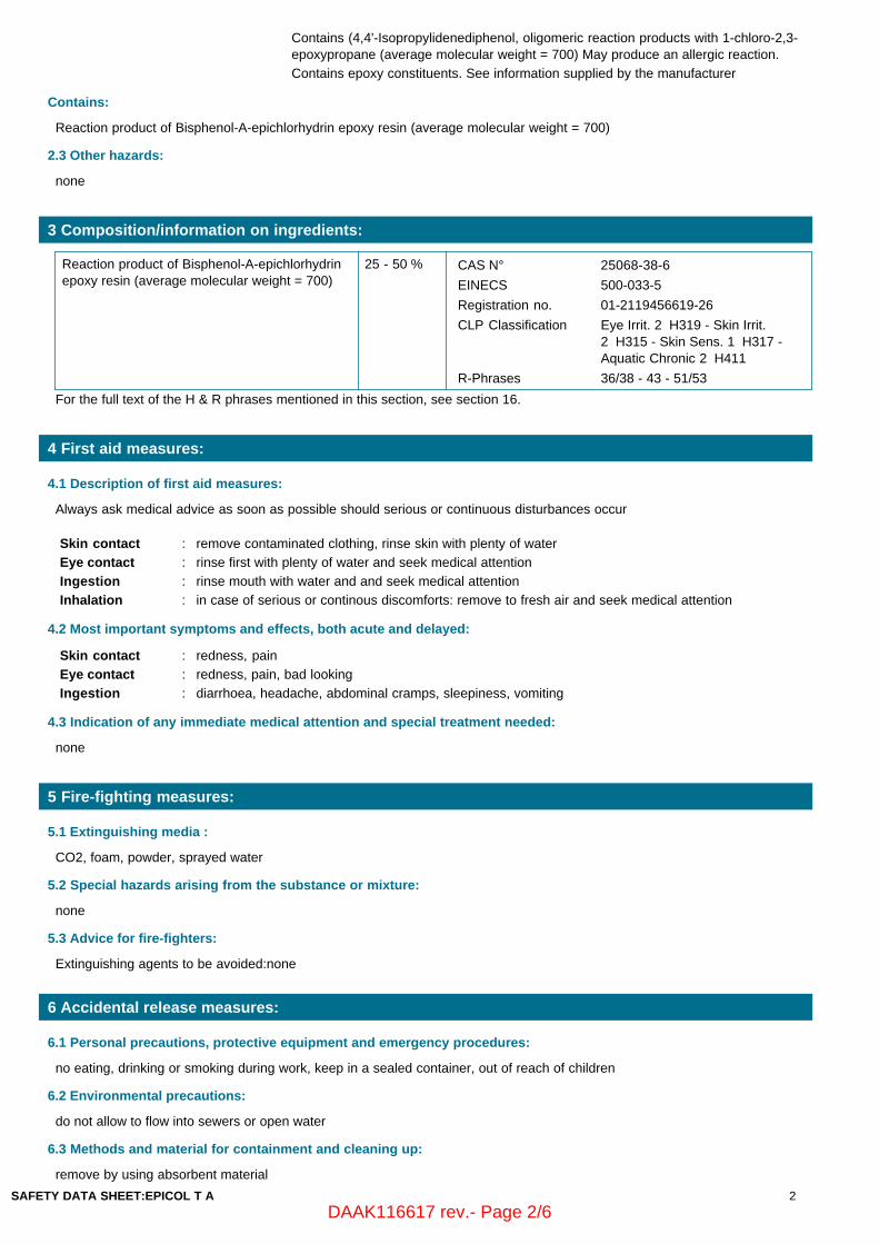
3 Composition/information on ingredients:
Reaction product of Bisphenol-A-epichlorhydrinepoxy resin (average molecular weight = 700)
25 - 50 % CAS N° 25068-38-6
EINECS 500-033-5
Registration no. 01-2119456619-26
CLP Classification Eye Irrit. 2 H319 - Skin Irrit.2 H315 - Skin Sens. 1 H317 -Aquatic Chronic 2 H411
R-Phrases 36/38 - 43 - 51/53
For the full text of the H & R phrases mentioned in this section, see section 16.
4 First aid measures:
4.1 Description of first aid measures:
Always ask medical advice as soon as possible should serious or continuous disturbances occur
Skin contact : remove contaminated clothing, rinse skin with plenty of water
Eye contact : rinse first with plenty of water and seek medical attention
Ingestion : rinse mouth with water and and seek medical attention
Inhalation : in case of serious or continous discomforts: remove to fresh air and seek medical attention
4.2 Most important symptoms and effects, both acute and delayed:
Skin contact : redness, pain
Eye contact : redness, pain, bad looking
Ingestion : diarrhoea, headache, abdominal cramps, sleepiness, vomiting
4.3 Indication of any immediate medical attention and special treatment needed:
none
5 Fire-fighting measures:
5.1 Extinguishing media :
CO2, foam, powder, sprayed water
5.2 Special hazards arising from the substance or mixture:
none
5.3 Advice for fire-fighters:
Extinguishing agents to be avoided:none
6 Accidental release measures:
6.1 Personal precautions, protective equipment and emergency procedures:
no eating, drinking or smoking during work, keep in a sealed container, out of reach of children
6.2 Environmental precautions:
do not allow to flow into sewers or open water
6.3 Methods and material for containment and cleaning up:
remove by using absorbent material
SAFETY DATA SHEET:EPICOL T A 2
DAAK116617 rev.- Page 2/6

6.4 Reference to other sections:
For further information check sections 8 & 13
7 Handling and storage:
7.1 Precautions for safe handling:
handle with care to avoid spillage
7.2 Conditions for safe storage, including any incompatibilities:
keep in a sealed container in a closed, frost-free, ventilated room Packing materials to be avoided: none
7.3 Specific end use(s):
special additive
8 Exposure controls/personal protection:
8.1 Control parameters:
Follows a list of the hazardous elements mentioned sub 3. of whicht he TLV value is known:
/,
8.2 Exposure controls:
Inhalationprotection
: none
Skin protection : gloves, chemical proof
Eye protection : safety glasses
Other protection : protective clothing
9 Physical and chemical properties:
9.1. Information on basic physical and chemical properties:
Melting point/melting range, ºC : /
Boiling point/Boiling range, ºC : /
pH : /
pH 1% diluted in water : /
Vapour pressure/20ºC,Pa : /
Vapour density, % : n/a
Relative density/20ºC : /
Appearance/20ºC : liquid
Flash point, ºC : /
Flammability (solid, gas) : n/a
Auto-ignition temperature,ºC : /
Upper flammability or explosive limit,Vol %
: n/a
Lower flammability or explosive limit,Vol %
: n/a
Explosive properties : n/a
Oxidising properties : n/a
Decomposition temperature, ºC : n.d.a.
Solubility in water : insoluble
Partition coefficient: n-octanol/water,%
: n/a
Odour : characteristic
Odour threshold : n/a
SAFETY DATA SHEET:EPICOL T A 3
DAAK116617 rev.- Page 3/6

Dynamic viscosity, mPa.s/20ºC : /
Kinematic viscosity, mm²/s/20ºC : /
Evaporation rate (n-BuAc = 1) : n/a
9.2 Other information:
Volatile organic component (VOC),%
: 0
Volatile organic component (VOC),g/l
: 0
10 Stability and reactivity:
10.1 Reactivity:
keep in a sealed container in a closed, frost-free, ventilated room
10.2 Chemical stability:
none known
10.3 Possibility of hazardous reactions:
none known
10.4 Conditions to avoid:
handle with care to avoid spillage
10.5 Incompatible materials:
none
10.6 Hazardous decomposition products:
none known
11 Toxicological information:
11.1 Information on toxicological effects:
About the substance itself : not applicable under actual EEC guidlines for preparations
General information : see ingredients under section 3
Calculated acute toxicity, LD50 oralrat, mg/kg
: 4764
12. Ecological information:
12.1 Toxicity:
not applicable under actual EEC guidlines for preparations
12.2 Persistence and degradability:
not applicable
12.3 Bioaccumulative potential:
not applicable under actual EEC guidlines for preparations
12.4 Mobility in soil:
Water hazard class, WGK: 3
12.5 Results of PBT and vPvB assessment:
not applicable under actual EEC guidlines for preparations
12.6 Other adverse effects:
not applicable under actual EEC guidlines for preparations
13 Disposal considerations:
13.1 Waste treatment methods:
SAFETY DATA SHEET:EPICOL T A 4
DAAK116617 rev.- Page 4/6
Draining into the sewers is not permitted. Removal should be carried out by licensed services.
Possible restrictive regulations by local authority should always be adhered to.
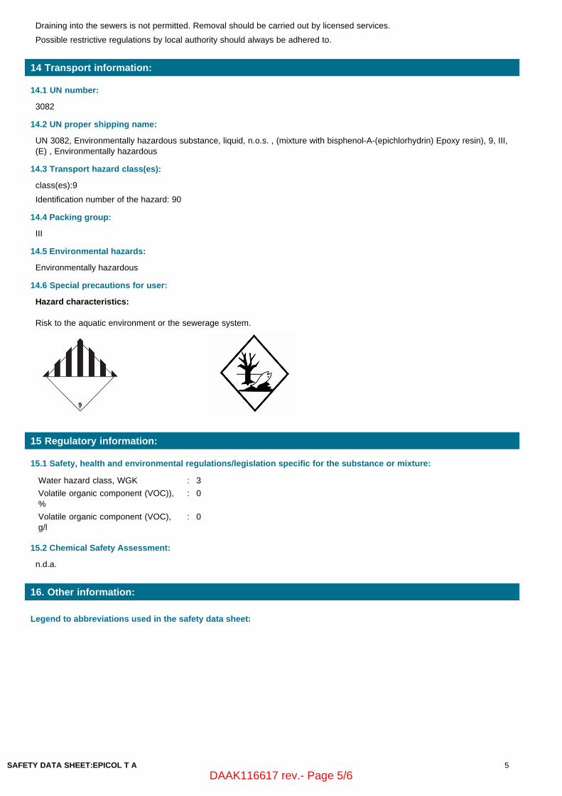
14 Transport information:
14.1 UN number:
3082
14.2 UN proper shipping name:
UN 3082, Environmentally hazardous substance, liquid, n.o.s. , (mixture with bisphenol-A-(epichlorhydrin) Epoxy resin), 9, III,(E) , Environmentally hazardous
14.3 Transport hazard class(es):
class(es):9
Identification number of the hazard: 90
14.4 Packing group:
III
14.5 Environmental hazards:
Environmentally hazardous
14.6 Special precautions for user:
Hazard characteristics:
Risk to the aquatic environment or the sewerage system.
15 Regulatory information:
15.1 Safety, health and environmental regulations/legislation specific for the substance or mixture:
Water hazard class, WGK : 3
Volatile organic component (VOC)),%
: 0
Volatile organic component (VOC),g/l
: 0
15.2 Chemical Safety Assessment:
n.d.a.
16. Other information:
Legend to abbreviations used in the safety data sheet:
SAFETY DATA SHEET:EPICOL T A 5
DAAK116617 rev.- Page 5/6
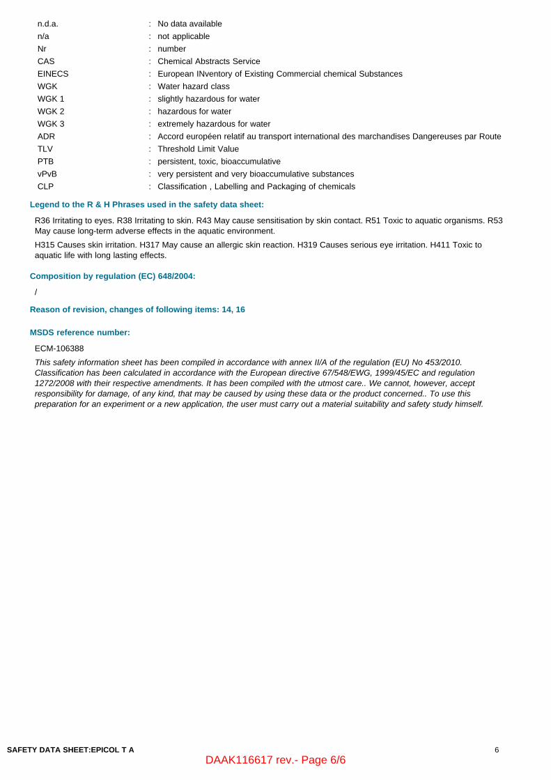
n.d.a. : No data available
n/a : not applicable
Nr : number
CAS : Chemical Abstracts Service
EINECS : European INventory of Existing Commercial chemical Substances
WGK : Water hazard class
WGK 1 : slightly hazardous for water
WGK 2 : hazardous for water
WGK 3 : extremely hazardous for water
ADR : Accord européen relatif au transport international des marchandises Dangereuses par Route
TLV : Threshold Limit Value
PTB : persistent, toxic, bioaccumulative
vPvB : very persistent and very bioaccumulative substances
CLP : Classification , Labelling and Packaging of chemicals
Legend to the R & H Phrases used in the safety data sheet:
R36 Irritating to eyes. R38 Irritating to skin. R43 May cause sensitisation by skin contact. R51 Toxic to aquatic organisms. R53May cause long-term adverse effects in the aquatic environment.
H315 Causes skin irritation. H317 May cause an allergic skin reaction. H319 Causes serious eye irritation. H411 Toxic toaquatic life with long lasting effects.
Composition by regulation (EC) 648/2004:
/
Reason of revision, changes of following items: 14, 16
MSDS reference number:
ECM-106388
This safety information sheet has been compiled in accordance with annex II/A of the regulation (EU) No 453/2010.Classification has been calculated in accordance with the European directive 67/548/EWG, 1999/45/EC and regulation1272/2008 with their respective amendments. It has been compiled with the utmost care.. We cannot, however, acceptresponsibility for damage, of any kind, that may be caused by using these data or the product concerned.. To use thispreparation for an experiment or a new application, the user must carry out a material suitability and safety study himself.
SAFETY DATA SHEET:EPICOL T A 6
DAAK116617 rev.- Page 6/6
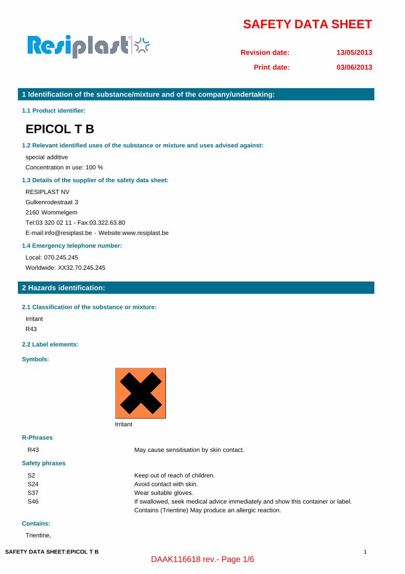
SAFETY DATA SHEET
Revision date: 13/05/2013
Print date: 03/06/2013
1 Identification of the substance/mixture and of the company/undertaking:
1.1 Product identifier:
EPICOL T B1.2 Relevant identified uses of the substance or mixture and uses advised against:
special additive
Concentration in use: 100 %
1.3 Details of the supplier of the safety data sheet:
RESIPLAST NV
Gulkenrodestraat 3
2160 Wommelgem
Tel:03 320 02 11 - Fax:03.322.63.80
E-mail:[email protected] - Website:www.resiplast.be
1.4 Emergency telephone number:
Local: 070.245.245
Worldwide: XX32.70.245.245
2 Hazards identification:
2.1 Classification of the substance or mixture:
Irritant
R43
2.2 Label elements:
Symbols:
Irritant
R-Phrases
R43 May cause sensitisation by skin contact.
Safety phrases
S2 Keep out of reach of children.
S24 Avoid contact with skin.
S37 Wear suitable gloves.
S46 If swallowed, seek medical advice immediately and show this container or label.
Contains (Trientine) May produce an allergic reaction.
Contains:
Trientine,
SAFETY DATA SHEET:EPICOL T B 1
DAAK116618 rev.- Page 1/6
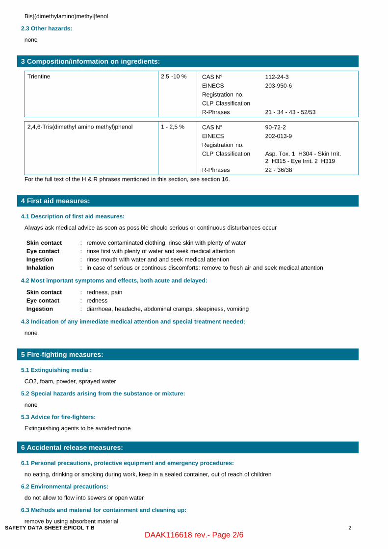
Bis[(dimethylamino)methyl]fenol
2.3 Other hazards:
none
3 Composition/information on ingredients:
Trientine 2,5 -10 % CAS N° 112-24-3
EINECS 203-950-6
Registration no.
CLP Classification
R-Phrases 21 - 34 - 43 - 52/53
2,4,6-Tris(dimethyl amino methyl)phenol 1 - 2,5 % CAS N° 90-72-2
EINECS 202-013-9
Registration no.
CLP Classification Asp. Tox. 1 H304 - Skin Irrit.2 H315 - Eye Irrit. 2 H319
R-Phrases 22 - 36/38
For the full text of the H & R phrases mentioned in this section, see section 16.
4 First aid measures:
4.1 Description of first aid measures:
Always ask medical advice as soon as possible should serious or continuous disturbances occur
Skin contact : remove contaminated clothing, rinse skin with plenty of water
Eye contact : rinse first with plenty of water and seek medical attention
Ingestion : rinse mouth with water and and seek medical attention
Inhalation : in case of serious or continous discomforts: remove to fresh air and seek medical attention
4.2 Most important symptoms and effects, both acute and delayed:
Skin contact : redness, pain
Eye contact : redness
Ingestion : diarrhoea, headache, abdominal cramps, sleepiness, vomiting
4.3 Indication of any immediate medical attention and special treatment needed:
none
5 Fire-fighting measures:
5.1 Extinguishing media :
CO2, foam, powder, sprayed water
5.2 Special hazards arising from the substance or mixture:
none
5.3 Advice for fire-fighters:
Extinguishing agents to be avoided:none
6 Accidental release measures:
6.1 Personal precautions, protective equipment and emergency procedures:
no eating, drinking or smoking during work, keep in a sealed container, out of reach of children
6.2 Environmental precautions:
do not allow to flow into sewers or open water
6.3 Methods and material for containment and cleaning up:
remove by using absorbent materialSAFETY DATA SHEET:EPICOL T B 2
DAAK116618 rev.- Page 2/6

6.4 Reference to other sections:
For further information check sections 8 & 13
7 Handling and storage:
7.1 Precautions for safe handling:
handle with care to avoid spillage
7.2 Conditions for safe storage, including any incompatibilities:
keep in a sealed container in a closed, frost-free, ventilated room Packing materials to be avoided: none
7.3 Specific end use(s):
special additive
8 Exposure controls/personal protection:
8.1 Control parameters:
Follows a list of the hazardous elements mentioned sub 3. of whicht he TLV value is known:
/,
8.2 Exposure controls:
Inhalationprotection
: none
Skin protection : gloves, chemical proof
Eye protection : none
Other protection : protective clothing
9 Physical and chemical properties:
9.1. Information on basic physical and chemical properties:
Melting point/melting range, ºC : /
Boiling point/Boiling range, ºC : /
pH : /
pH 1% diluted in water : /
Vapour pressure/20ºC,Pa : /
Vapour density, % : n/a
Relative density/20ºC : /
Appearance/20ºC : liquid
Flash point, ºC : /
Flammability (solid, gas) : n/a
Auto-ignition temperature,ºC : /
Upper flammability or explosive limit,Vol %
: n/a
Lower flammability or explosive limit,Vol %
: n/a
Explosive properties : n/a
Oxidising properties : n/a
Decomposition temperature, ºC : n.d.a.
Solubility in water : insoluble
Partition coefficient: n-octanol/water,%
: n/a
Odour : characteristic
Odour threshold : n/a
SAFETY DATA SHEET:EPICOL T B 3
DAAK116618 rev.- Page 3/6

Dynamic viscosity, mPa.s/20ºC : /
Kinematic viscosity, mm²/s/20ºC : /
Evaporation rate (n-BuAc = 1) : n/a
9.2 Other information:
Volatile organic component (VOC),%
: 0
Volatile organic component (VOC),g/l
: 0
10 Stability and reactivity:
10.1 Reactivity:
keep in a sealed container in a closed, frost-free, ventilated room
10.2 Chemical stability:
none known
10.3 Possibility of hazardous reactions:
none known
10.4 Conditions to avoid:
handle with care to avoid spillage
10.5 Incompatible materials:
none
10.6 Hazardous decomposition products:
none known
11 Toxicological information:
11.1 Information on toxicological effects:
About the substance itself : not applicable under actual EEC guidlines for preparations
General information : see ingredients under section 3
Calculated acute toxicity, LD50 oralrat, mg/kg
: > 5000
12. Ecological information:
12.1 Toxicity:
not applicable under actual EEC guidlines for preparations
12.2 Persistence and degradability:
not applicable
12.3 Bioaccumulative potential:
not applicable under actual EEC guidlines for preparations
12.4 Mobility in soil:
Water hazard class, WGK: 1
12.5 Results of PBT and vPvB assessment:
not applicable under actual EEC guidlines for preparations
12.6 Other adverse effects:
not applicable under actual EEC guidlines for preparations
13 Disposal considerations:
13.1 Waste treatment methods:
SAFETY DATA SHEET:EPICOL T B 4
DAAK116618 rev.- Page 4/6

Draining into the sewers is not permitted. Removal should be carried out by licensed services.
Possible restrictive regulations by local authority should always be adhered to.
14 Transport information:
14.1 UN number:
/
14.2 UN proper shipping name:
ADR, IMDG, ICAO/IATA not applicable, /, /
14.3 Transport hazard class(es):
class(es):
Identification number of the hazard: /
14.4 Packing group:
/
14.5 Environmental hazards:
Not dangerous to the environment
14.6 Special precautions for user:
15 Regulatory information:
15.1 Safety, health and environmental regulations/legislation specific for the substance or mixture:
Water hazard class, WGK : 1
Volatile organic component (VOC)),%
: 0
Volatile organic component (VOC),g/l
: 0
15.2 Chemical Safety Assessment:
n.d.a.
16. Other information:
Legend to abbreviations used in the safety data sheet:
SAFETY DATA SHEET:EPICOL T B 5
DAAK116618 rev.- Page 5/6

n.d.a. : No data available
n/a : not applicable
Nr : number
CAS : Chemical Abstracts Service
EINECS : European INventory of Existing Commercial chemical Substances
WGK : Water hazard class
WGK 1 : slightly hazardous for water
WGK 2 : hazardous for water
WGK 3 : extremely hazardous for water
ADR : Accord européen relatif au transport international des marchandises Dangereuses par Route
TLV : Threshold Limit Value
PTB : persistent, toxic, bioaccumulative
vPvB : very persistent and very bioaccumulative substances
CLP : Classification , Labelling and Packaging of chemicals
Legend to the R & H Phrases used in the safety data sheet:
R21 Harmful in contact with skin. R22 Harmful if swallowed. R34 Causes burns. R36 Irritating to eyes. R38 Irritating to skin. R43May cause sensitisation by skin contact. R52 Harmful to aquatic organisms. R53 May cause long-term adverse effects in theaquatic environment.
H304 May be fatal if swallowed and enters airways. H315 Causes skin irritation. H319 Causes serious eye irritation.
Composition by regulation (EC) 648/2004:
/
Reason of revision, changes of following items: /
MSDS reference number:
ECM-106389
This safety information sheet has been compiled in accordance with annex II/A of the regulation (EU) No 453/2010.Classification has been calculated in accordance with the European directive 67/548/EWG, 1999/45/EC and regulation1272/2008 with their respective amendments. It has been compiled with the utmost care.. We cannot, however, acceptresponsibility for damage, of any kind, that may be caused by using these data or the product concerned.. To use thispreparation for an experiment or a new application, the user must carry out a material suitability and safety study himself.
SAFETY DATA SHEET:EPICOL T B 6
DAAK116618 rev.- Page 6/6

EnergoProFin Instruction Manual Order number: SNL/15023.M5-M8 Document nr: DAAF302908 revision –
Copyright Wärtsilä. All rights reserved. Nothing from this publication may be reproduced or disclosed without prior written approval of Wärtsilä.
END OF MANUAL