ENCLOSuRE shielding SOLUTIONS - Mercado · PDF fileCopper Beryllium Fingerstock EMI designers...
36
ENCLOSuRE shielding SOLUTIONS The Leading Edge In EMI Shielding Technology
Transcript of ENCLOSuRE shielding SOLUTIONS - Mercado · PDF fileCopper Beryllium Fingerstock EMI designers...
ENCLOSuRE shielding SOLUTIONS
The Leading Edge In EMI Shielding Technology

1. Our visiOn (An aspiration worthy to strive for)
We are committed to being the most reliable and innovative supplier in the EMI/RFI industry, and as our name implies, the leader. In order to achieve this we will consistently strive to provide you with unparalleled service, innovation, and solutions.
2. Our missiOn (Our daily commitment to you)
We are committed to consistently provide you with innovation and flexibility of design. Our engineering expertise and conscientious, outstanding customer service that will provide you with the right product, delivered on time. We are dedicated to making you look good to your customers. We want your repeat business.
3. Our prOducts (Precision engineered to work in your application)
We are committed to product excellence. We offer our patented Circuit Board Shields (CBS), an extensive range of copper beryllium (CuBE), a Conductive Elastomer product line, TechVENT Honeycomb Panels, TechMESH knitted mesh, microwave absorbers, and FerriShield Ferrites. Using this diverse product line, Leader Tech is positioned to provide you with a ‘total shielding solution’ for all of your EMI/RFI shielding requirements.
4. Our Facilities (Continually expanding to meet your needs)
Leader Tech is committed to expansion wherever and whenever necessary. We are constantly expanding our hardware and software capabilities while investing in new equipment to manufacture and deliver the most precise and cost efficient shielding in the industry. Through the continuous support and backing of our parent company HEICO, the possibilities for new space and equipment are an ever-present reality.
5. Our services (Consistent reliability each time you order)
We are committed to excellent service. Our staff undergoes a rigorous daily product, sales, and service training in order to serve you better. We want your calls answered by a person, not a machine, someone trained to qualify your needs and get answers to you when you need them. At Leader Tech we believe that the right people and the right equipment go hand in hand.
ISO 9001: 2008 CERTIFIED
✔RoHSCOMPLIANT
5 S t e p C o m m i t m e n t To O u r V a l u e d C u s t o m e r s
Table of Contents
Application of Fingerstock Gaskets
Slot Mount Series ............................................................................................................................
Adhesive Mount Series ................................................................................................................
Dome Top Series ..............................................................................................................................
Low Profile Series ...........................................................................................................................
Compact PCI Series .......................................................................................................................
Folded Series ......................................................................................................................................
Twist Series .........................................................................................................................................
Clip-On Series ....................................................................................................................................
Contact Series ....................................................................................................................................
Ordering Information & Adhesive Mounting Instructions
Metals Galvanic Compatibility Chart
Compression/Deflection Performance and EMI Shielding Effectiveness
Precision Metal Stampings .......................................................................................................
TechSIL Conductive Elastomers ............................................................................................
TechSIL Oriented Wire .................................................................................................................
TechMESH Knitted Wire ..............................................................................................................
TechMESH Elastomer Core Wire ...........................................................................................
TechMESH Combo Strip ..............................................................................................................
TechVENT Honeycomb Panels ................................................................................................
FSG Fabric Shielding Gaskets.................................................................................................
Products and Literature ...............................................................................................................
1
2
4
6
6
7
7
8
10
12
13
16
17
18
19
20
22
23
24
25
26
28
32
C o p p e r B e r y l l i u m F i n g e r s t o c k
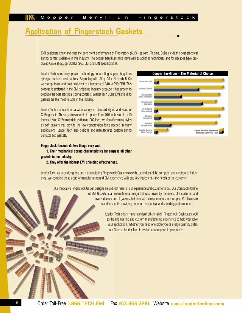
EMI designers know and trust the consistent performance of Fingerstock (CuBe) gaskets. To date, CuBe yields the best electrical spring contact available in this industry. The copper beryllium mills have well established techniques and for decades have pro-duced CuBe alloys per ASTM, SAE, JIS, and DIN specifications.
Leader Tech uses only proven technology in creating copper beryllium springs, contacts and gaskets. Beginning with Alloy 25 (1/4 hard) BeCu we stamp, form, and post heat-treat to a hardness of 340 to 390 DPH. This process is preferred in the EMI shielding industry because it has proven to produce the best electrical spring contacts. Leader Tech CuBe EMI shielding gaskets are the most reliable in the industry.
Leader Tech manufactures a wide variety of standard styles and sizes of CuBe gaskets. These gaskets operate in spaces from .010 inches up to .410 inches. Using CuBe materials as thin as .002 inch, we also offer many styles as soft gaskets that provide the low compression force needed in many applications. Leader Tech also designs and manufactures custom spring contacts and gaskets.
Fingerstock Gaskets do two things very well: 1. Their mechanical spring characteristics far surpass all other gaskets in the industry. 2. They offer the highest EMI shielding effectiveness.
Leader Tech has been designing and manufacturing Fingerstock Gaskets since the early days of the computer and electronics indus-tries. We combine these years of manufacturing and EMI experience with one key ingredient – the needs of the customer.
Our innovative Fingerstock Gasket designs are a direct result of our experience and customer input. Our Compact PCI line of EMI Gaskets is an example of a design that was driven by the needs of a customer and
evolved into a line of gaskets that meet all the requirements for Compact PCI faceplate standards while providing superior mechanical and shielding performance.
Leader Tech offers many standard off-the-shelf Fingerstock Gaskets as well as the engineering and custom manufacturing experience to help you solve your application. Whether you need one prototype or a large quantity order, our Team at Leader Tech is available to respond to your needs.
Copper Beryllium – The Material of Choice
Order Toll-Free 1.866.TECH.EMI Fax 813.855.3291 Website www.leadertechinc.com
Application of Fingerstock Gaskets
2
C o p p e r B e r y l l i u m F i n g e r s t o c k
Order Toll-Free 1.866.TECH.EMI Fax 813.855.3291 Website www.leadertechinc.com
11-32AF-XX-16 0.11 2.80 0.32 8.10 0.169 4.30 0.187 4.75 0.004 0.102 0.085 2.159 0.020 0.508 0.09 2.286 0.26 6.604 0.04 1.016 16 406 85
11-S-32AF-XX-16 0.11 2.80 0.32 8.10 0.169 4.30 0.187 4.75 0.002 0.050 0.085 2.159 0.020 0.508 0.09 2.286 0.26 6.604 0.04 1.016 16 406 85
22-60AF-XX-16 0.22 5.59 0.60 15.24 0.250 6.35 0.282 7.16 0.005 0.127 0.140 3.556 0.035 0.889 0.14 3.556 0.52 13.208 0.07 1.778 16 406 57
22-S-60AF-XX-16 0.22 5.59 0.60 15.24 0.250 6.35 0.282 7.16 0.003 0.080 0.140 3.556 0.035 0.889 0.14 3.556 0.52 13.208 0.07 1.778 16 406 57
4
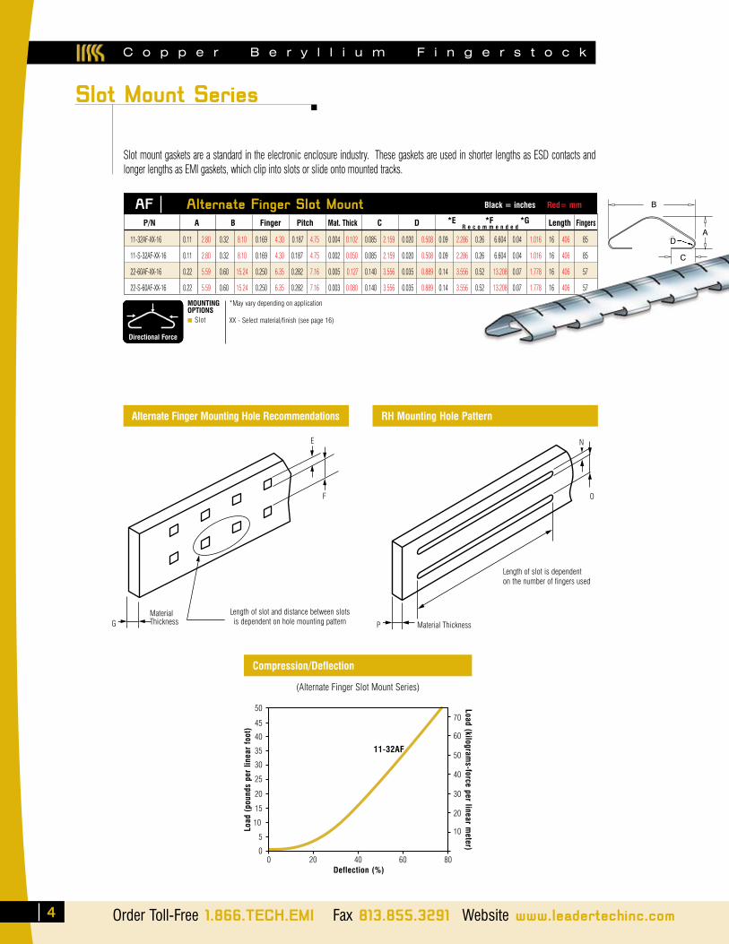
AF Alternate Finger Slot Mount Black = inches Red= mm
P/N A B Finger Pitch Mat. Thick C D *E *F *G Length Fingers
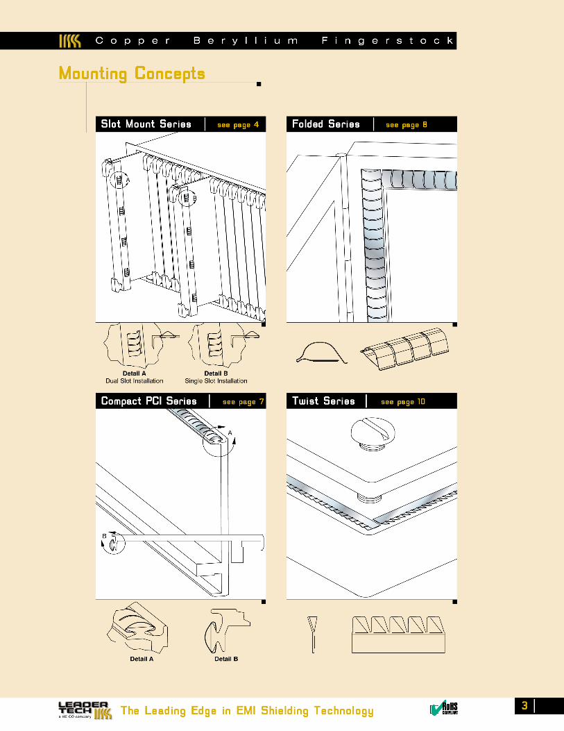
Slot Mount Series
Slot mount gaskets are a standard in the electronic enclosure industry. These gaskets are used in shorter lengths as ESD contacts and longer lengths as EMI gaskets, which clip into slots or slide onto mounted tracks.
MaterialThickness
Length of slot and distance between slotsis dependent on hole mounting pattern
E
F
G
Alternate Finger Mounting Hole Recommendations
Compression/Deflection
(Alternate Finger Slot Mount Series)
50
45
40
35
30
25
20
15
10
5
0
70
60
50
40
30
20
10
0 20 40 60 80
Load
(po
unds
per
line
ar f
oot)
Load (kilograms-force per linear m
eter)
Deflection (%)
11-32AF
R e c o m m e n d e d
Length of slot is dependenton the number of fingers used
N
O
Material Thickness
RH Mounting Hole Pattern
P
MOUNTINGOPTIONS■ Slot
B
A
C
*May vary depending on application
XX - Select material/finish (see page 16)
Directional Force
D

The Leading Edge in EMI Shielding Technology ✔RoHSCOMPLIANT
5
DA
B
C
Directional Force
MOUNTINGOPTIONS■ Slot
P/N A B Finger Pitch Mat. Thick C D *N *O *P Length Fingers
11-28RH-XX-16 0.11 2.80 0.28 7.11 0.169 4.30 0.187 4.75 0.003 0.076 0.075 1.90 0.02 0.76 0.09 2.29 0.22 5.59 0.04 1.02 16 406 86
11-28RH-XX-.17 0.11 2.80 0.28 7.11 0.169 4.30 0.187 4.75 0.003 0.076 0.075 1.90 0.02 0.76 0.09 2.29 0.22 5.59 0.04 1.02 0.17 4 1
11-28RH-XX-.36 0.11 2.80 0.28 7.11 0.169 4.30 0.187 4.75 0.003 0.076 0.075 1.90 0.02 0.76 0.09 2.29 0.22 5.59 0.04 1.02 0.36 9 2
11-28RH-XX-.54 0.11 2.80 0.28 7.11 0.169 4.30 0.187 4.75 0.003 0.076 0.075 1.90 0.02 0.76 0.09 2.29 0.22 5.59 0.04 1.02 0.54 14 3
11-28RH-XX-.73 0.11 2.80 0.28 7.11 0.169 4.30 0.187 4.75 0.003 0.076 0.075 1.90 0.02 0.76 0.09 2.29 0.22 5.59 0.04 1.02 0.73 19 4
11-S-28RH-XX-16 0.11 2.80 0.28 7.11 0.169 4.30 0.187 4.75 0.002 0.050 0.075 1.90 0.02 0.76 0.09 2.29 0.22 5.59 0.04 1.02 16 406 86
11-S-28RH-XX-.17 0.11 2.80 0.28 7.11 0.169 4.30 0.187 4.75 0.002 0.050 0.075 1.90 0.02 0.76 0.09 2.29 0.22 5.59 0.04 1.02 0.17 4 1
11-S-28RH-XX-.36 0.11 2.80 0.28 7.11 0.169 4.30 0.187 4.75 0.002 0.050 0.075 1.90 0.02 0.76 0.09 2.29 0.22 5.59 0.04 1.02 0.36 9 2
11-S-28RH-XX-.54 0.11 2.80 0.28 7.11 0.169 4.30 0.187 4.75 0.002 0.050 0.075 1.90 0.02 0.76 0.09 2.29 0.22 5.59 0.04 1.02 0.54 14 3
11-S-28RH-XX-.73 0.11 2.80 0.28 7.11 0.169 4.30 0.187 4.75 0.002 0.050 0.075 1.90 0.02 0.76 0.09 2.29 0.22 5.59 0.04 1.02 0.73 19 4
11-32RH-XX-16 0.11 2.80 0.32 8.10 0.169 4.30 0.187 4.75 0.003 0.102 0.09 2.29 0.02 0.51 0.09 2.29 0.26 6.60 0.04 1.02 16 406 86
11-32RH-XX-.17 0.11 2.80 0.32 8.10 0.169 4.30 0.187 4.75 0.003 0.102 0.09 2.29 0.02 0.51 0.09 2.29 0.26 6.60 0.04 1.02 0.17 4 1
11-32RH-XX-.36 0.11 2.80 0.32 8.10 0.169 4.30 0.187 4.75 0.003 0.102 0.09 2.29 0.02 0.51 0.09 2.29 0.26 6.60 0.04 1.02 0.36 9 2
11-32RH-XX-.54 0.11 2.80 0.32 8.10 0.169 4.30 0.187 4.75 0.003 0.102 0.09 2.29 0.02 0.51 0.09 2.29 0.26 6.60 0.04 1.02 0.54 14 3
11-32RH-XX-.73 0.11 2.80 0.32 8.10 0.169 4.30 0.187 4.75 0.003 0.102 0.09 2.29 0.02 0.51 0.09 2.29 0.26 6.60 0.04 1.02 0.73 19 4
11-S-32RH-XX-16 0.11 2.80 0.32 8.10 0.169 4.30 0.187 4.75 0.002 0.050 0.09 2.29 0.02 0.51 0.09 2.29 0.26 6.60 0.04 1.02 16 406 86
11-S-32RH-XX-.17 0.11 2.80 0.32 8.10 0.169 4.30 0.187 4.75 0.002 0.050 0.09 2.29 0.02 0.51 0.09 2.29 0.26 6.60 0.04 1.02 0.17 4 1
11-S-32RH-XX-.36 0.11 2.80 0.32 8.10 0.169 4.30 0.187 4.75 0.002 0.050 0.09 2.29 0.02 0.51 0.09 2.29 0.26 6.60 0.04 1.02 0.36 9 2
11-S-32RH-XX-.54 0.11 2.80 0.32 8.10 0.169 4.30 0.187 4.75 0.002 0.050 0.09 2.29 0.02 0.51 0.09 2.29 0.26 6.60 0.04 1.02 0.54 14 3
11-S-32RH-XX-.73 0.11 2.80 0.32 8.10 0.169 4.30 0.187 4.75 0.002 0.050 0.09 2.29 0.02 0.51 0.09 2.29 0.26 6.60 0.04 1.02 0.73 19 4
13-30RH-XX-16 0.13 3.30 0.30 7.62 0.169 4.30 0.187 4.75 0.004 0.102 0.09 2.29 0.03 0.76 0.09 2.29 0.25 6.35 0.05 1.27 16 406 86
13-37RH-XX-16 0.13 3.30 0.37 9.40 0.225 5.72 0.250 6.35 0.003 0.080 0.09 2.29 0.02 0.51 0.09 2.29 0.31 7.87 0.04 1.02 16 406 64
13-37RH-XX-.23 0.13 3.30 0.37 9.40 0.225 5.72 0.250 6.35 0.003 0.080 0.09 2.29 0.02 0.51 0.09 2.29 0.31 7.87 0.04 1.02 0.23 5.7 1
13-37RH-XX-.48 0.13 3.30 0.37 9.40 0.225 5.72 0.250 6.35 0.003 0.080 0.09 2.29 0.02 0.51 0.09 2.29 0.31 7.87 0.04 1.02 0.48 12.1 2
13-37RH-XX-.73 0.13 3.30 0.37 9.40 0.225 5.72 0.250 6.35 0.003 0.080 0.09 2.29 0.02 0.51 0.09 2.29 0.31 7.87 0.04 1.02 0.73 18.4 3
13-37RH-XX-.98 0.13 3.30 0.37 9.40 0.225 5.72 0.250 6.35 0.003 0.080 0.09 2.29 0.02 0.51 0.09 2.29 0.31 7.87 0.04 1.02 0.98 24.8 4
13-S-37RH-XX-16 0.13 3.30 0.37 9.40 0..225 5.72 0.250 6.35 0.002 0.050 0.09 2.29 0.02 0.51 0.09 2.29 0.31 7.87 0.04 1.02 16 406 64
13-S-37RH-XX-.23 0.13 3.30 0.37 9.40 0.225 5.72 0.250 6.35 0.002 0.050 0.09 2.29 0.02 0.51 0.09 2.29 0.31 7.87 0.04 1.02 0.23 5.7 1
13-S-37RH-XX-.48 0.13 3.30 0.37 9.40 0.225 5.72 0.250 6.35 0.002 0.050 0.09 2.29 0.02 0.51 0.09 2.29 0.31 7.87 0.04 1.02 0.48 12.1 2
13-S-37RH-XX-.73 0.13 3.30 0.37 9.40 0.225 5.72 0.250 6.35 0.002 0.050 0.09 2.29 0.02 0 .51 0.09 2.29 0.31 7.87 0.04 1.02 0.73 18.4 3
13-S-37RH-XX-.98 0.13 3.30 0.37 9.40 0.225 5.72 0.250 6.35 0.002 0.050 0.09 2.29 0.02 0.51 0.09 2.29 0.31 7.87 0.04 1.02 0.98 24.8 4
22-60RH-XX-16 0.22 5.60 0.60 15.20 0.250 6.40 0.282 7.16 0.005 0.130 0.14 3.56 0.04 1.02 0.14 3.56 0.52 13.21 0.06 1.52 16 406 57
22-60RH-XX-.25 0.22 5.60 0.60 15.20 0.250 6.40 0.282 7.16 0.005 0.130 0.14 3.56 0.04 1.02 0.14 3.56 0.52 13.21 0.06 1.52 0.25 6.4 1
22-60RH-XX-.53 0.22 5.60 0.60 15.20 0.250 6.40 0.282 7.16 0.005 0.130 0.14 3.56 0.04 1.02 0.14 3.56 0.52 13.21 0.06 1.52 0.53 13.5 2
22-S-60RH-XX-16 0.22 5.60 0.60 15.20 0.250 6.40 0.282 7.16 0.003 0.080 0.14 3.56 0.04 1.02 0.14 3.56 0.52 13.21 0.06 1.52 16 406 57
22-S-60RH-XX-.25 0.22 5.60 0.60 15.20 0.250 6.40 0.282 7.16 0.003 0.080 0.14 3.56 0.04 1.02 0.14 3.56 0.52 13.21 0.06 1.52 0.25 6 1
22-S-60RH-XX-.53 0.22 5.60 0.60 15.20 0.250 6.40 0.282 7.16 0.003 0.080 0.14 3.56 0.04 1.02 0.14 3.56 0.52 13.21 0.06 1.52 0.53 14 2
RH Slot Mount Black = inches Red= mm
Slot Mount Series (cont.)
R e c o m m e n d e d
*May vary depending on application
XX - Select material/finish (see page 16)
C o p p e r B e r y l l i u m F i n g e r s t o c k
C o p p e r B e r y l l i u m F i n g e r s t o c k
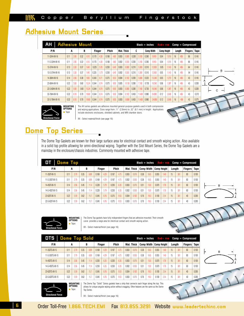
Adhesive Mount Series
The Dome Top Gaskets are known for their large surface area for electrical contact and smooth wiping action. Also available in a solid top profile allowing for omni-directional wiping. Together with the Slot Mount Series, the Dome Top Gaskets are a mainstay in the enclosure/chassis industries. Commonly mounted with adhesive tape.
AH Adhesive Mount Black = inches Red= mm Comp = Compressed
A
B
C
The AH series gaskets are adhesive mounted general-purpose gaskets used in both compression and wiping applications. Sizes range from .11” (2.8mm) to .32” (8.1 mm) in height. Applications include electronic enclosures, shielded cabinets, and MRI chamber doors.
XX - Select material/finish (see page 16)Directional Force
MOUNTINGOPTIONS■ Tape
Directional Force
MOUNTINGOPTIONS■ Tape
The Dome Top gaskets have fully independent fingers that are adhesive mounted. Their smooth curve provides a large area for electrical contact and smooth wiping action.
XX - Select material/finish (see page 16)
11-32AH-XX-16 0.11 2.80 0.32 8.10 0.170 4.30 0.188 4.80 0.003 0.080 0.200 5.100 0.390 9.910 0.04 1.016 16 406 86 0.145
11-S-32AH-XX-16 0.11 2.80 0.32 8.10 0.170 4.30 0.188 4.80 0.002 0.050 0.200 5.100 0.390 9.910 0.04 1.016 16 406 86 0.145
13-37AH-XX-16 0.13 3.30 0.37 9.40 0.225 5.70 0.250 6.40 0.003 0.080 0.210 5.300 0.510 12.950 0.05 1.143 16 406 64 0.145
13-S-37AH-XX-16 0.13 3.30 0.37 9.40 0.225 5.70 0.250 6.40 0.002 0.050 0.210 5.300 0.510 12.950 0.05 1.143 16 406 64 0.145
14-38AH-XX-16 0.14 3.56 0.38 9.65 0.343 8.71 0.375 9.53 0.004 0.102 0.200 5.080 0.525 13.340 0.05 1.270 16 406 43 0.145
22-60AH-XX-16 0.22 5.60 0.60 15.24 0.344 8.74 0.375 9.50 0.005 0.130 0.280 7.100 0.730 18.540 0.06 1.397 16 406 43 0.200
22-S-60AH-XX-16 0.22 5.60 0.60 15.24 0.344 8.74 0.375 9.50 0.003 0.080 0.280 7.100 0.730 18.540 0.06 1.397 16 406 43 0.200
32-78AH-XX-16 0.32 8.10 0.78 19.80 0.344 8.74 0.375 9.50 0.004 0.102 0.450 11.400 0.980 24.890 0.12 3.048 16 406 43 0.375
32-S-78AH-XX-16 0.32 8.10 0.78 19.80 0.344 8.74 0.375 9.50 0.003 0.080 0.450 11.400 0.980 24.890 0.12 3.048 16 406 43 0.375
P/N A B Finger Pitch Mat. Thick C Comp Width Comp Height Length Fingers Tape
DT Dome Top Black = inches Red= mm Comp = Compressed
11-35DT-XX-15 0.11 2.79 0.35 8.89 0.169 4.29 0.187 4.75 0.003 0.076 0.38 9.65 0.055 1.40 15 381 80 0.100
11-S-35DT-XX-15 0.11 2.79 0.35 8.89 0.169 4.29 0.187 4.75 0.002 0.050 0.38 9.65 0.055 1.40 15 381 80 0.100
14-45DT-XX-15 0.14 3.56 0.45 11.4 0.228 5.79 0.250 6.35 0.003 0.076 0.51 13.0 0.070 1.78 15 381 60 0.100
14-S-45DT-XX-15 0.14 3.56 0.45 11.4 0.228 5.79 0.250 6.35 0.002 0.050 0.51 13.0 0.070 1.78 15 381 60 0.100
22-62DT-XX-15 0.22 5.59 0.62 15.7 0.345 8.76 0.375 9.53 0.004 0.102 0.76 19.3 0.100 2.54 15 381 40 0.200
22-S-62DT-XX-15 0.22 5.59 0.62 15.7 0.345 8.76 0.375 9.53 0.003 0.076 0.76 19.3 0.100 2.54 15 381 40 0.200
P/N A B Finger Pitch Mat. Thick Comp Width Comp Height Length Fingers Tape
DTS Dome Top Solid Black = inches Red= mm Comp = Compressed
MOUNTINGOPTIONS■ Tape
The Dome Top “Solid” Series gaskets have a strip that connects each finger along the top. This allows for unique angular wiping action without snagging. Other features are the same as the Dome Top Series.
XX - Select material/finish (see page 16)Directional Force
11-35DTS-XX-15 0.11 2.79 0.35 8.89 0.169 4.29 0.187 4.75 0.003 0.076 0.38 9.65 0.055 1.40 15 381 80 0.100
11-S-35DTS-XX-15 0.11 2.79 0.35 8.89 0.169 4.29 0.187 4.75 0.002 0.050 0.38 9.65 0.055 1.40 15 381 80 0.100
14-45DTS-XX-15 0.14 3.56 0.45 11.4 0.250 6.35 0.250 6.35 0.003 0.076 0.51 13.0 0.070 1.78 15 381 60 0.100
14-S-45DTS-XX-15 0.14 3.56 0.45 11.4 0.250 6.35 0.250 6.35 0.002 0.050 0.51 13.0 0.070 1.78 15 381 60 0.100
22-62DTS-XX-15 0.22 5.59 0.62 15.7 0.345 8.76 0.375 9.53 0.004 0.102 0.76 19.3 0.100 2.54 15 381 40 0.200
22-S-62DTS-XX-15 0.22 5.59 0.62 15.7 0.345 8.76 0.375 9.53 0.003 0.076 0.76 19.3 0.100 2.54 15 381 40 0.200
P/N A B Finger Pitch Mat. Thick Comp Width Comp Height Length Fingers Tape
Dome Top Series
6 Order Toll-Free 1.866.TECH.EMI Fax 813.855.3291 Website www.leadertechinc.com
A
A
B
B
A
A
D A
B
C
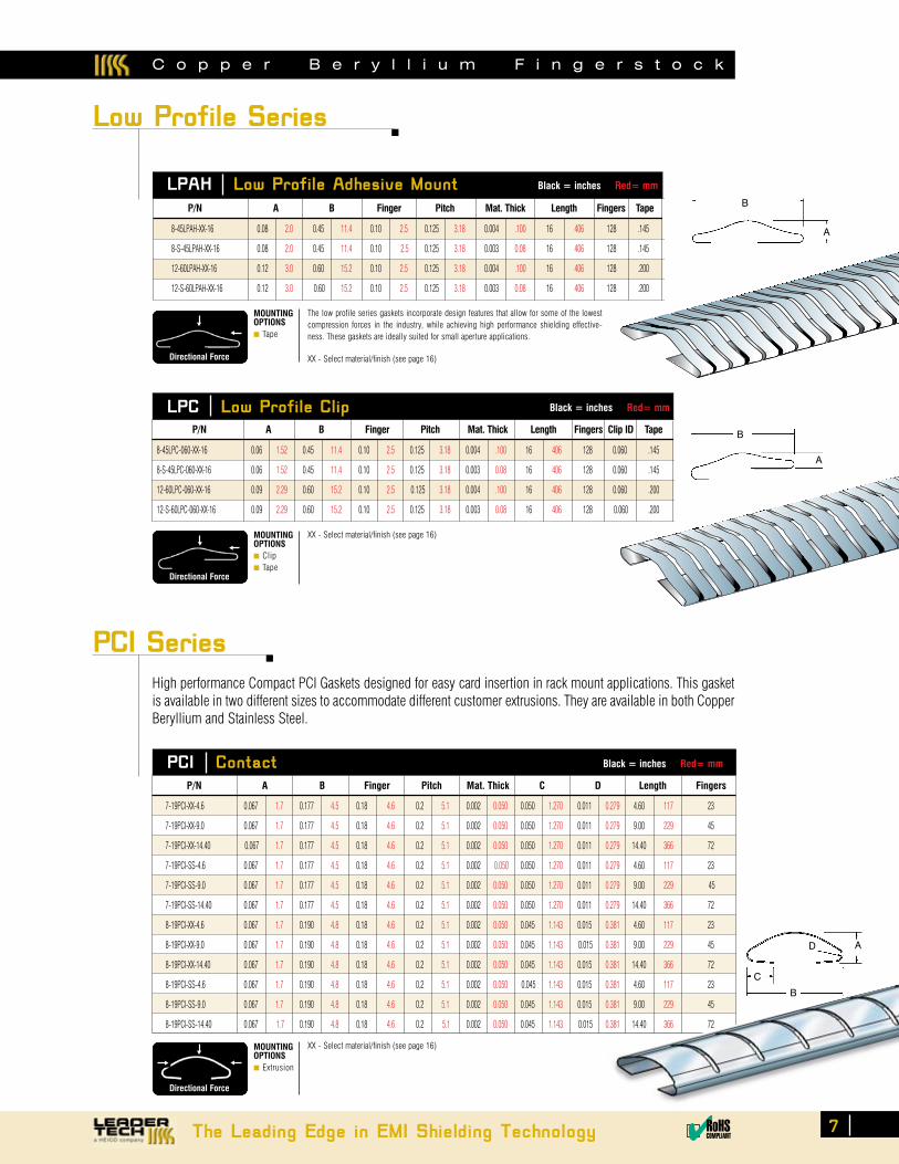
Low Profile Series
LPAH Low Profile Adhesive Mount Black = inches Red= mm
LPC Low Profile Clip Black = inches Red= mm
PCI Contact Black = inches Red= mm
PCI Series
High performance Compact PCI Gaskets designed for easy card insertion in rack mount applications. This gasket is available in two different sizes to accommodate different customer extrusions. They are available in both Copper Beryllium and Stainless Steel.
A
B
MOUNTINGOPTIONS■ Tape
The low profile series gaskets incorporate design features that allow for some of the lowest compression forces in the industry, while achieving high performance shielding effective-ness. These gaskets are ideally suited for small aperture applications.
XX - Select material/finish (see page 16)
A
B
Directional Force
MOUNTINGOPTIONS■ Clip■ Tape
Directional Force
MOUNTINGOPTIONS■ Extrusion
Directional Force
8-45LPAH-XX-16 0.08 2.0 0.45 11.4 0.10 2.5 0.125 3.18 0.004 .100 16 406 128 .145
8-S-45LPAH-XX-16 0.08 2.0 0.45 11.4 0.10 2.5 0.125 3.18 0.003 0.08 16 406 128 .145
12-60LPAH-XX-16 0.12 3.0 0.60 15.2 0.10 2.5 0.125 3.18 0.004 .100 16 406 128 .200
12-S-60LPAH-XX-16 0.12 3.0 0.60 15.2 0.10 2.5 0.125 3.18 0.003 0.08 16 406 128 .200
P/N A B Finger Pitch Mat. Thick Length Fingers Tape
8-45LPC-060-XX-16 0.06 1.52 0.45 11.4 0.10 2.5 0.125 3.18 0.004 .100 16 406 128 0.060 .145
8-S-45LPC-060-XX-16 0.06 1.52 0.45 11.4 0.10 2.5 0.125 3.18 0.003 0.08 16 406 128 0.060 .145
12-60LPC-060-XX-16 0.09 2.29 0.60 15.2 0.10 2.5 0.125 3.18 0.004 .100 16 406 128 0.060 .200
12-S-60LPC-060-XX-16 0.09 2.29 0.60 15.2 0.10 2.5 0.125 3.18 0.003 0.08 16 406 128 0.060 .200
P/N A B Finger Pitch Mat. Thick Length Fingers Clip ID Tape
7-19PCI-XX-4.6 0.067 1.7 0.177 4.5 0.18 4.6 0.2 5.1 0.002 0.050 0.050 1.270 0.011 0.279 4.60 117 23
7-19PCI-XX-9.0 0.067 1.7 0.177 4.5 0.18 4.6 0.2 5.1 0.002 0.050 0.050 1.270 0.011 0.279 9.00 229 45
7-19PCI-XX-14.40 0.067 1.7 0.177 4.5 0.18 4.6 0.2 5.1 0.002 0.050 0.050 1.270 0.011 0.279 14.40 366 72
7-19PCI-SS-4.6 0.067 1.7 0.177 4.5 0.18 4.6 0.2 5.1 0.002 0.050 0.050 1.270 0.011 0.279 4.60 117 23
7-19PCI-SS-9.0 0.067 1.7 0.177 4.5 0.18 4.6 0.2 5.1 0.002 0.050 0.050 1.270 0.011 0.279 9.00 229 45
7-19PCI-SS-14.40 0.067 1.7 0.177 4.5 0.18 4.6 0.2 5.1 0.002 0.050 0.050 1.270 0.011 0.279 14.40 366 72
8-19PCI-XX-4.6 0.067 1.7 0.190 4.8 0.18 4.6 0.2 5.1 0.002 0.050 0.045 1.143 0.015 0.381 4.60 117 23
8-19PCI-XX-9.0 0.067 1.7 0.190 4.8 0.18 4.6 0.2 5.1 0.002 0.050 0.045 1.143 0.015 0.381 9.00 229 45
8-19PCI-XX-14.40 0.067 1.7 0.190 4.8 0.18 4.6 0.2 5.1 0.002 0.050 0.045 1.143 0.015 0.381 14.40 366 72
8-19PCI-SS-4.6 0.067 1.7 0.190 4.8 0.18 4.6 0.2 5.1 0.002 0.050 0.045 1.143 0.015 0.381 4.60 117 23
8-19PCI-SS-9.0 0.067 1.7 0.190 4.8 0.18 4.6 0.2 5.1 0.002 0.050 0.045 1.143 0.015 0.381 9.00 229 45
8-19PCI-SS-14.40 0.067 1.7 0.190 4.8 0.18 4.6 0.2 5.1 0.002 0.050 0.045 1.143 0.015 0.381 14.40 366 72
P/N A B Finger Pitch Mat. Thick C D Length Fingers
XX - Select material/finish (see page 16)
XX - Select material/finish (see page 16)
C o p p e r B e r y l l i u m F i n g e r s t o c k
The Leading Edge in EMI Shielding Technology ✔RoHSCOMPLIANT
7

A
B
Black = inches Red= mm
8-25FSC-XX-16 0.08 2.03 0.250 6.35 0.170 4.32 0.188 4.78 0.003 0.076 0.048 1.22 16 406 85 0.250
11-37FSC-XX-16 0.11 2.79 0.375 9.5 0.170 4.3 0.188 4.8 0.003 0.076 0.065 1.65 16 406 85 0.250
11-S-37FSC-XX-16 0.11 2.79 0.375 9.5 0.170 4.3 0.188 4.8 0.002 0.050 0.065 1.65 16 406 85 0.250
14-51FSC-XX-16 0.14 3.56 0.510 13.0 0.228 5.8 0.250 6.4 0.003 0.076 0.100 2.54 16 406 64 0.250
14-S-51FSC-XX-16 0.14 3.56 0.510 13.0 0.228 5.8 0.250 6.4 0.002 0.050 0.100 2.54 16 406 64 0.375
23-76FSC-XX-24 0.23 5.84 0.760 19.3 0.343 8.7 0.375 9.5 0.004 0.102 0.115 2.92 24 610 64 0.375
P/N A B Finger Pitch Mat. Thick Comp Height Length Fingers Tape
C o p p e r B e r y l l i u m F i n g e r s t o c k
Folded Series
8
Leader Tech's Folded Gasket series are industry standard general-purpose gaskets that allow a large range of deflection and compression forces. These gaskets are available with or without tape for alternate attachment methods. Also available in a snag-free version where, under compression, the leading edge of the gasket slides into an extended and folded base which prevents possible damage to the gasket.
FS Folded Black = inches Red= mm
Order Toll-Free 1.866.TECH.EMI Fax 813.855.3291 Website www.leadertechinc.com
A
B
C
MOUNTINGOPTIONS■ Tape■ Solder■ Rivet
The Leader Tech FS gaskets are industry standard general-purpose gaskets that allow a large range of deflection and compression forces. These gaskets are available without tape for alternate attachment methods. Consult factory for information.
XX - Select material/finish (see page 16)Directional Force
11-28-FS-XX-16 0.11 2.79 0.28 7.11 0.170 4.32 0.188 4.78 0.003 0.076 0.24 5.842 0.37 9.4 0.065 1.65 16 406 85 0.145
11-S-28-FS-XX-16 0.11 2.79 0.28 7.11 0.170 4.32 0.188 4.78 0.002 0.050 0.24 5.842 0.37 9.4 0.065 1.65 16 406 85 0.145
14-37FS-XX-16 0.14 3.56 0.37 9.40 0.228 5.79 0.250 6.35 0.003 0.076 0.32 7.874 0.50 12.7 0.100 2.54 16 406 64 0.200
14-37FS-XX-300 0.14 3.56 0.37 9.40 0.228 5.84 0.250 6.35 0.003 0.076 0.32 7.874 0.50 12.7 0.100 2.54 300 7620 1200 0.200
14-S-37FS-XX-16 0.14 3.56 0.37 9.40 0.228 5.79 0.250 6.35 0.002 0.050 0.31 7.874 0.50 12.7 0.100 2.54 16 406 64 0.200
23-60FS-XX-24 0.23 5.84 0.60 15.24 0.343 8.71 0.375 9.53 0.004 0.102 0.50 12.700 0.77 19.6 0.115 2.92 24 610 64 0.250
23-S-60FS-XX-24 0.23 5.84 0.60 15.24 0.343 8.71 0.375 9.53 0.003 0.076 0.50 12.700 0.77 19.6 0.115 2.92 24 610 64 0.250
25-78FS-XX-24 0.25 6.35 0.78 19.81 0.335 8.51 0.375 9.53 0.005 0.127 0.53 13.462 0.94 23.9 0.115 2.92 24 610 64 0.375
25-78FS-XX-300 0.25 6.35 0.78 19.81 0.340 8.64 0.375 9.53 0.005 0.127 0.53 13.462 0.94 23.9 0.150 3.81 300 7620 800 0.375
25-S-78FS-XX-24 0.25 6.35 0.78 19.81 0.335 8.51 0.375 9.53 0.003 0.076 0.53 13.462 0.94 23.9 0.150 3.81 24 610 64 0.375
25-S-78FS-XX-300 0.25 6.35 0.78 19.81 0.335 8.51 0.375 9.53 0.003 0.076 0.53 13.462 0.94 23.9 0.150 3.81 300 7620 800 0.375
41-113FS-XX-12 0.41 10.41 1.13 28.78 0.460 11.68 0.500 12.57 0.007 0.178 0.80 20.320 1.94 49.3 0.230 .584 12 305 24 0.375
P/N A B Finger Pitch Mat. Thick C Comp Length Comp Height Length Fingers Tape
FSC Folded
MOUNTINGOPTIONS■ Tape■ Solder■ Rivet
The FSC was created to provide snag free gaskets with FS gasket features. The base of the gasket is extended from the mounting area and then folded up, over, down, and then comes to rest over the leading edge of the formed spring. Under compression, the leading edge of the gasket slides under and is “captured.” This “no snag” feature is also used to prevent possible gasket damage.
XX - Select material/finish (see page 16)
Directional Force
9
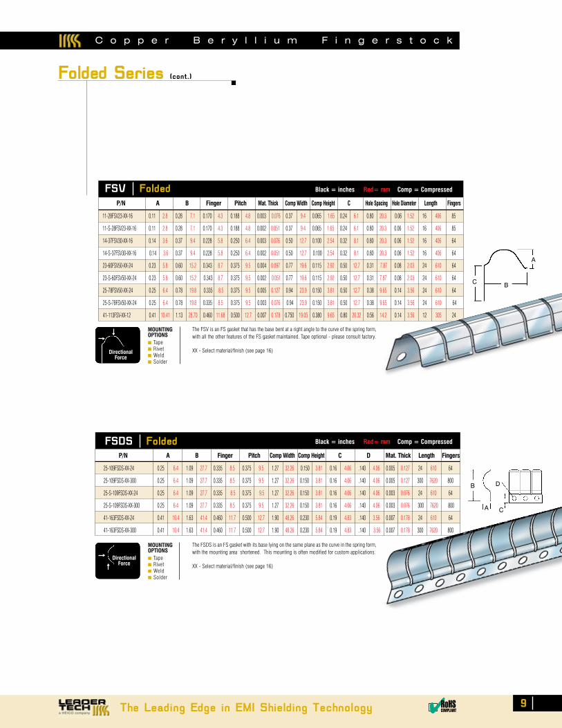
FSV Folded Black = inches Red= mm Comp = Compressed
FSDS Folded Black = inches Red= mm Comp = Compressed
Folded Series (cont.)
A
B
C
D
A
BC
MOUNTINGOPTIONS■ Tape■ Rivet■ Weld■ Solder
Directional Force
The FSV is an FS gasket that has the base bent at a right angle to the curve of the spring form, with all the other features of the FS gasket maintained. Tape optional - please consult factory.
XX - Select material/finish (see page 16)
11-28FSV23-XX-16 0.11 2.8 0.28 7.1 0.170 4.3 0.188 4.8 0.003 0.076 0.37 9.4 0.065 1.65 0.24 6.1 0.80 20.3 0.06 1.52 16 406 85
11-S-28FSV23-XX-16 0.11 2.8 0.28 7.1 0.170 4.3 0.188 4.8 0.002 0.051 0.37 9.4 0.065 1.65 0.24 6.1 0.80 20.3 0.06 1.52 16 406 85
14-37FSV30-XX-16 0.14 3.6 0.37 9.4 0.228 5.8 0.250 6.4 0.003 0.076 0.50 12.7 0.100 2.54 0.32 8.1 0.80 20.3 0.06 1.52 16 406 64
14-S-37FSV30-XX-16 0.14 3.6 0.37 9.4 0.228 5.8 0.250 6.4 0.002 0.051 0.50 12.7 0.100 2.54 0.32 8.1 0.80 20.3 0.06 1.52 16 406 64
23-60FSV50-XX-24 0.23 5.8 0.60 15.2 0.343 8.7 0.375 9.5 0.004 0.097 0.77 19.6 0.115 2.92 0.50 12.7 0.31 7.87 0.08 2.03 24 610 64
23-S-60FSV50-XX-24 0.23 5.8 0.60 15.2 0.343 8.7 0.375 9.5 0.002 0.051 0.77 19.6 0.115 2.92 0.50 12.7 0.31 7.87 0.08 2.03 24 610 64
25-78FSV50-XX-24 0.25 6.4 0.78 19.8 0.335 8.5 0.375 9.5 0.005 0.127 0.94 23.9 0.150 3.81 0.50 12.7 0.38 9.65 0.14 3.56 24 610 64
25-S-78FSV50-XX-24 0.25 6.4 0.78 19.8 0.335 8.5 0.375 9.5 0.003 0.076 0.94 23.9 0.150 3.81 0.50 12.7 0.38 9.65 0.14 3.56 24 610 64
41-113FSV-XX-12 0.41 10.41 1.13 28.70 0.460 11.68 0.500 12.7 0.007 0.178 0.750 19.05 0.380 9.65 0.80 20.32 0.56 14.2 0.14 3.56 12 305 24
P/N A B Finger Pitch Mat. Thick Comp Width Comp Height C Hole Spacing Hole Diameter Length Fingers
25-109FSDS-XX-24 0.25 6.4 1.09 27.7 0.335 8.5 0.375 9.5 1.27 32.26 0.150 3.81 0.16 4.06 .140 4.06 0.005 0.127 24 610 64
25-109FSDS-XX-300 0.25 6.4 1.09 27.7 0.335 8.5 0.375 9.5 1.27 32.26 0.150 3.81 0.16 4.06 .140 4.06 0.005 0.127 300 7620 800
25-S-109FSDS-XX-24 0.25 6.4 1.09 27.7 0.335 8.5 0.375 9.5 1.27 32.26 0.150 3.81 0.16 4.06 .140 4.06 0.003 0.076 24 610 64
25-S-109FSDS-XX-300 0.25 6.4 1.09 27.7 0.335 8.5 0.375 9.5 1.27 32.26 0.150 3.81 0.16 4.06 .140 4.06 0.003 0.076 300 7620 800
41-163FSDS-XX-24 0.41 10.4 1.63 41.4 0.460 11.7 0.500 12.7 1.90 48.26 0.230 5.84 0.19 4.83 .140 3.56 0.007 0.178 24 610 64
41-163FSDS-XX-300 0.41 10.4 1.63 41.4 0.460 11.7 0.500 12.7 1.90 48.26 0.230 5.84 0.19 4.83 .140 3.56 0.007 0.178 300 7620 800
P/N A B Finger Pitch Comp Width Comp Height C D Mat. Thick Length Fingers
The Leading Edge in EMI Shielding Technology ✔RoHSCOMPLIANT
MOUNTINGOPTIONS■ Tape■ Rivet■ Weld■ Solder
Directional Force
The FSDS is an FS gasket with its base lying on the same plane as the curve in the spring form, with the mounting area shortened. This mounting is often modified for custom applications.
XX - Select material/finish (see page 16)
C o p p e r B e r y l l i u m F i n g e r s t o c k
C o p p e r B e r y l l i u m F i n g e r s t o c k
AB
C
A
B
C
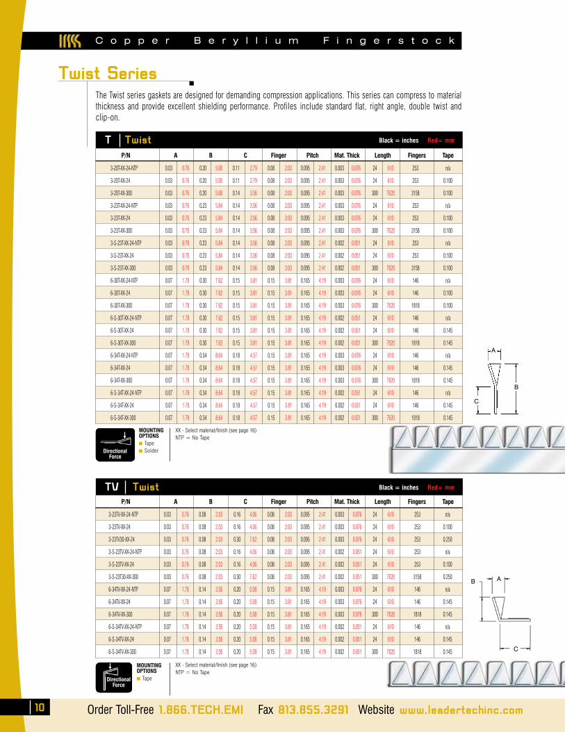
Twist Series
10 Order Toll-Free 1.866.TECH.EMI Fax 813.855.3291 Website www.leadertechinc.com
The Twist series gaskets are designed for demanding compression applications. This series can compress to material thickness and provide excellent shielding performance. Profiles include standard flat, right angle, double twist and clip-on.
T Twist Black = inches Red= mm
3-20T-XX-24-NTP 0.03 0.76 0.20 5.08 0.11 2.79 0.08 2.03 0.095 2.41 0.003 0.076 24 610 253 n/a
3-20T-XX-24 0.03 0.76 0.20 5.08 0.11 2.79 0.08 2.03 0.095 2.41 0.003 0.076 24 610 253 0.100
3-20T-XX-300 0.03 0.76 0.20 5.08 0.14 3.56 0.08 2.03 0.095 2.41 0.003 0.076 300 7620 3158 0.100
3-23T-XX-24-NTP 0.03 0.76 0.23 5.84 0.14 3.56 0.08 2.03 0.095 2.41 0.003 0.076 24 610 253 n/a
3-23T-XX-24 0.03 0.76 0.23 5.84 0.14 3.56 0.08 2.03 0.095 2.41 0.003 0.076 24 610 253 0.100
3-23T-XX-300 0.03 0.76 0.23 5.84 0.14 3.56 0.08 2.03 0.095 2.41 0.003 0.076 300 7620 3158 0.100
3-S-23T-XX-24-NTP 0.03 0.76 0.23 5.84 0.14 3.56 0.08 2.03 0.095 2.41 0.002 0.051 24 610 253 n/a
3-S-23T-XX-24 0.03 0.76 0.23 5.84 0.14 3.56 0.08 2.03 0.095 2.41 0.002 0.051 24 610 253 0.100
3-S-23T-XX-300 0.03 0.76 0.23 5.84 0.14 3.56 0.08 2.03 0.095 2.41 0.002 0.051 300 7620 3158 0.100
6-30T-XX-24-NTP 0.07 1.78 0.30 7.62 0.15 3.81 0.15 3.81 0.165 4.19 0.003 0.076 24 610 146 n/a
6-30T-XX-24 0.07 1.78 0.30 7.62 0.15 3.81 0.15 3.81 0.165 4.19 0.003 0.076 24 610 146 0.100
6-30T-XX-300 0.07 1.78 0.30 7.62 0.15 3.81 0.15 3.81 0.165 4.19 0.003 0.076 300 7620 1818 0.100
6-S-30T-XX-24-NTP 0.07 1.78 0.30 7.62 0.15 3.81 0.15 3.81 0.165 4.19 0.002 0.051 24 610 146 n/a
6-S-30T-XX-24 0.07 1.78 0.30 7.62 0.15 3.81 0.15 3.81 0.165 4.19 0.002 0.051 24 610 146 0.145
6-S-30T-XX-300 0.07 1.78 0.30 7.62 0.15 3.81 0.15 3.81 0.165 4.19 0.002 0.051 300 7620 1818 0.145
6-34T-XX-24-NTP 0.07 1.78 0.34 8.64 0.18 4.57 0.15 3.81 0.165 4.19 0.003 0.076 24 610 146 n/a
6-34T-XX-24 0.07 1.78 0.34 8.64 0.18 4.57 0.15 3.81 0.165 4.19 0.003 0.076 24 610 146 0.145
6-34T-XX-300 0.07 1.78 0.34 8.64 0.18 4.57 0.15 3.81 0.165 4.19 0.003 0.076 300 7620 1818 0.145
6-S-34T-XX-24-NTP 0.07 1.78 0.34 8.64 0.18 4.57 0.15 3.81 0.165 4.19 0.002 0.051 24 610 146 n/a
6-S-34T-XX-24 0.07 1.78 0.34 8.64 0.18 4.57 0.15 3.81 0.165 4.19 0.002 0.051 24 610 146 0.145
6-S-34T-XX-300 0.07 1.78 0.34 8.64 0.18 4.57 0.15 3.81 0.165 4.19 0.002 0.051 300 7620 1818 0.145
P/N A B C Finger Pitch Mat. Thick Length Fingers Tape
MOUNTINGOPTIONS■ Tape■ SolderDirectional
Force
XX - Select material/finish (see page 16)NTP = No Tape
MOUNTINGOPTIONS■ TapeDirectional
Force
XX - Select material/finish (see page 16)NTP = No Tape
TV Twist Black = inches Red= mm
3-23TV-XX-24-NTP 0.03 0.76 0.08 2.03 0.16 4.06 0.08 2.03 0.095 2.41 0.003 0.076 24 610 253 n/a
3-23TV-XX-24 0.03 0.76 0.08 2.03 0.16 4.06 0.08 2.03 0.095 2.41 0.003 0.076 24 610 253 0.100
3-23TV30-XX-24 0.03 0.76 0.08 2.03 0.30 7.62 0.08 2.03 0.095 2.41 0.003 0.076 24 610 253 0.250
3-S-23TV-XX-24-NTP 0.03 0.76 0.08 2.03 0.16 4.06 0.08 2.03 0.095 2.41 0.002 0.051 24 610 253 n/a
3-S-23TV-XX-24 0.03 0.76 0.08 2.03 0.16 4.06 0.08 2.03 0.095 2.41 0.002 0.051 24 610 253 0.100
3-S-23T30-XX-300 0.03 0.76 0.08 2.03 0.30 7.62 0.08 2.03 0.095 2.41 0.002 0.051 300 7620 3158 0.250
6-34TV-XX-24-NTP 0.07 1.78 0.14 3.56 0.20 5.08 0.15 3.81 0.165 4.19 0.003 0.076 24 610 146 n/a
6-34TV-XX-24 0.07 1.78 0.14 3.56 0.20 5.08 0.15 3.81 0.165 4.19 0.003 0.076 24 610 146 0.145
6-34TV-XX-300 0.07 1.78 0.14 3.56 0.20 5.08 0.15 3.81 0.165 4.19 0.003 0.076 300 7620 1818 0.145
6-S-34TV-XX-24-NTP 0.07 1.78 0.14 3.56 0.20 5.08 0.15 3.81 0.165 4.19 0.002 0.051 24 610 146 n/a
6-S-34TV-XX-24 0.07 1.78 0.14 3.56 0.20 5.08 0.15 3.81 0.165 4.19 0.002 0.051 24 610 146 0.145
6-S-34TV-XX-300 0.07 1.78 0.14 3.56 0.20 5.08 0.15 3.81 0.165 4.19 0.002 0.051 300 7620 1818 0.145
P/N A B C Finger Pitch Mat. Thick Length Fingers Tape
The Leading Edge in EMI Shielding Technology ✔RoHSCOMPLIANT
11
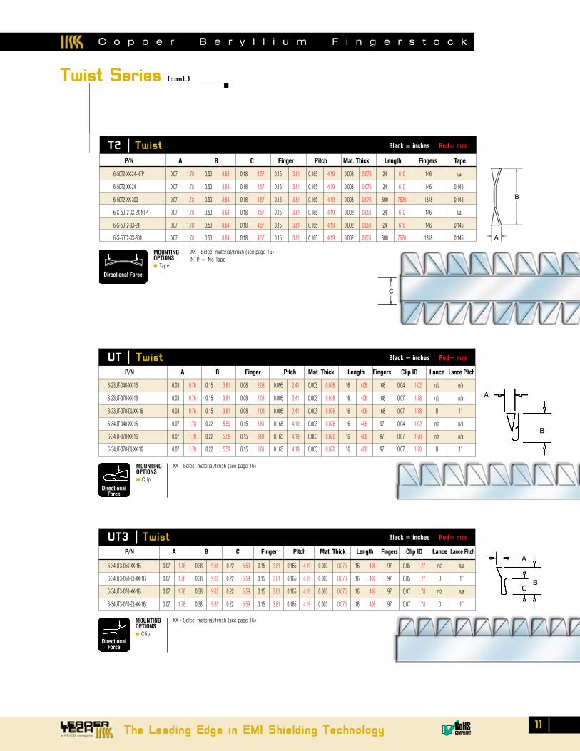
Twist Series (cont.)
T2 Twist Black = inches Red= mm
UT Twist Black = inches Red= mm
A
B
6-50T2-XX-24-NTP 0.07 1.78 0.50 8.64 0.18 4.57 0.15 3.81 0.165 4.19 0.003 0.076 24 610 146 n/a
6-50T2-XX-24 0.07 1.78 0.50 8.64 0.18 4.57 0.15 3.81 0.165 4.19 0.003 0.076 24 610 146 0.145
6-50T2-XX-300 0.07 1.78 0.50 8.64 0.18 4.57 0.15 3.81 0.165 4.19 0.003 0.076 300 7620 1818 0.145
6-S-50T2-XX-24-NTP 0.07 1.78 0.50 8.64 0.18 4.57 0.15 3.81 0.165 4.19 0.002 0.051 24 610 146 n/a
6-S-50T2-XX-24 0.07 1.78 0.50 8.64 0.18 4.57 0.15 3.81 0.165 4.19 0.002 0.051 24 610 146 0.145
6-S-50T2-XX-300 0.07 1.78 0.50 8.64 0.18 4.57 0.15 3.81 0.165 4.19 0.002 0.051 300 7620 1818 0.145
P/N A B C Finger Pitch Mat. Thick Length Fingers Tape
3-23UT-040-XX-16 0.03 0.76 0.15 3.81 0.08 2.03 0.095 2.41 0.003 0.076 16 406 168 0.04 1.02 n/a n/a
3-23UT-070-XX-16 0.03 0.76 0.15 3.81 0.08 2.03 0.095 2.41 0.003 0.076 16 406 168 0.07 1.78 n/a n/a
3-23UT-070-DL-XX-16 0.03 0.76 0.15 3.81 0.08 2.03 0.095 2.41 0.003 0.076 16 406 168 0.07 1.78 D 1”
6-34UT-040-XX-16 0.07 1.78 0.22 5.59 0.15 3.81 0.165 4.19 0.003 0.076 16 406 97 0.04 1.02 n/a n/a
6-34UT-070-XX-16 0.07 1.78 0.22 5.59 0.15 3.81 0.165 4.19 0.003 0.076 16 406 97 0.07 1.78 n/a n/a
6-34UT-070-DL-XX-16 0.07 1.78 0.22 5.59 0.15 3.81 0.165 4.19 0.003 0.076 16 406 97 0.07 1.78 D 1”
P/N A B Finger Pitch Mat. Thick Length Fingers Clip ID Lance Lance Pitch
MOUNTINGOPTIONS■ Clip
Directional Force
A
B
C
MOUNTINGOPTIONS■ Tape
Directional Force
XX - Select material/finish (see page 16)NTP = No Tape
XX - Select material/finish (see page 16)
C o p p e r B e r y l l i u m F i n g e r s t o c k
UT3 Twist Black = inches Red= mm
6-34UT3-050-XX-16 0.07 1.78 0.38 9.65 0.22 5.59 0.15 3.81 0.165 4.19 0.003 0.076 16 406 97 0.05 1.27 n/a n/a
6-34UT3-050-DL-XX-16 0.07 1.78 0.38 9.65 0.22 5.59 0.15 3.81 0.165 4.19 0.003 0.076 16 406 97 0.05 1.27 D 1”
6-34UT3-070-XX-16 0.07 1.78 0.38 9.65 0.22 5.59 0.15 3.81 0.165 4.19 0.003 0.076 16 406 97 0.07 1.78 n/a n/a
6-34UT3-070-DL-XX-16 0.07 1.78 0.38 9.65 0.22 5.59 0.15 3.81 0.165 4.19 0.003 0.076 16 406 97 0.07 1.78 D 1”
P/N A B C Finger Pitch Mat. Thick Length Fingers Clip ID Lance Lance PitchA
BC
MOUNTINGOPTIONS■ Clip
Directional Force
XX - Select material/finish (see page 16)
C o p p e r B e r y l l i u m F i n g e r s t o c k
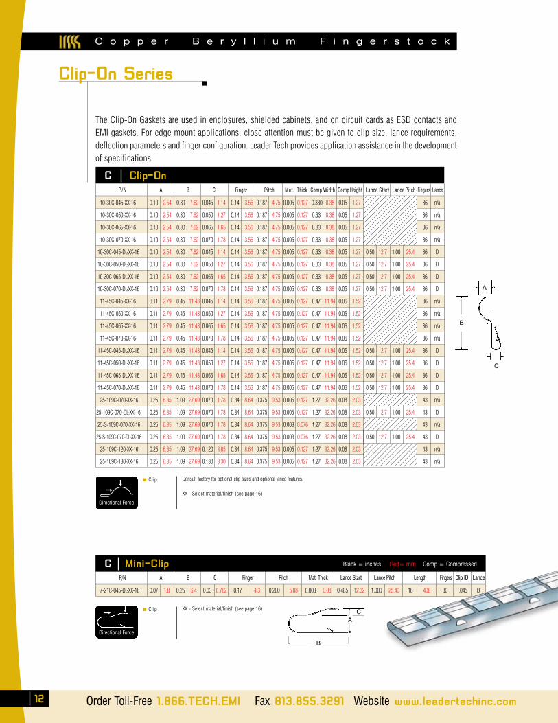
The Clip-On Gaskets are used in enclosures, shielded cabinets, and on circuit cards as ESD contacts and EMI gaskets. For edge mount applications, close attention must be given to clip size, lance requirements, deflection parameters and finger configuration. Leader Tech provides application assistance in the development of specifications.
C Clip-On
C Mini-Clip Black = inches Red= mm Comp = Compressed
10-30C-045-XX-16 0.10 2.54 0.30 7.62 0.045 1.14 0.14 3.56 0.187 4.75 0.005 0.127 0.330 8.38 0.05 1.27 86 n/a
10-30C-050-XX-16 0.10 2.54 0.30 7.62 0.050 1.27 0.14 3.56 0.187 4.75 0.005 0.127 0.33 8.38 0.05 1.27 86 n/a
10-30C-065-XX-16 0.10 2.54 0.30 7.62 0.065 1.65 0.14 3.56 0.187 4.75 0.005 0.127 0.33 8.38 0.05 1.27 86 n/a
10-30C-070-XX-16 0.10 2.54 0.30 7.62 0.070 1.78 0.14 3.56 0.187 4.75 0.005 0.127 0.33 8.38 0.05 1.27 86 n/a
10-30C-045-DL-XX-16 0.10 2.54 0.30 7.62 0.045 1.14 0.14 3.56 0.187 4.75 0.005 0.127 0.33 8.38 0.05 1.27 0.50 12.7 1.00 25.4 86 D
10-30C-050-DL-XX-16 0.10 2.54 0.30 7.62 0.050 1.27 0.14 3.56 0.187 4.75 0.005 0.127 0.33 8.38 0.05 1.27 0.50 12.7 1.00 25.4 86 D
10-30C-065-DL-XX-16 0.10 2.54 0.30 7.62 0.065 1.65 0.14 3.56 0.187 4.75 0.005 0.127 0.33 8.38 0.05 1.27 0.50 12.7 1.00 25.4 86 D
10-30C-070-DL-XX-16 0.10 2.54 0.30 7.62 0.070 1.78 0.14 3.56 0.187 4.75 0.005 0.127 0.33 8.38 0.05 1.27 0.50 12.7 1.00 25.4 86 D
11-45C-045-XX-16 0.11 2.79 0.45 11.43 0.045 1.14 0.14 3.56 0.187 4.75 0.005 0.127 0.47 11.94 0.06 1.52 86 n/a
11-45C-050-XX-16 0.11 2.79 0.45 11.43 0.050 1.27 0.14 3.56 0.187 4.75 0.005 0.127 0.47 11.94 0.06 1.52 86 n/a
11-45C-065-XX-16 0.11 2.79 0.45 11.43 0.065 1.65 0.14 3.56 0.187 4.75 0.005 0.127 0.47 11.94 0.06 1.52 86 n/a
11-45C-070-XX-16 0.11 2.79 0.45 11.43 0.070 1.78 0.14 3.56 0.187 4.75 0.005 0.127 0.47 11.94 0.06 1.52 86 n/a
11-45C-045-DL-XX-16 0.11 2.79 0.45 11.43 0.045 1.14 0.14 3.56 0.187 4.75 0.005 0.127 0.47 11.94 0.06 1.52 0.50 12.7 1.00 25.4 86 D
11-45C-050-DL-XX-16 0.11 2.79 0.45 11.43 0.050 1.27 0.14 3.56 0.187 4.75 0.005 0.127 0.47 11.94 0.06 1.52 0.50 12.7 1.00 25.4 86 D
11-45C-065-DL-XX-16 0.11 2.79 0.45 11.43 0.065 1.65 0.14 3.56 0.187 4.75 0.005 0.127 0.47 11.94 0.06 1.52 0.50 12.7 1.00 25.4 86 D
11-45C-070-DL-XX-16 0.11 2.79 0.45 11.43 0.070 1.78 0.14 3.56 0.187 4.75 0.005 0.127 0.47 11.94 0.06 1.52 0.50 12.7 1.00 25.4 86 D
25-109C-070-XX-16 0.25 6.35 1.09 27.69 0.070 1.78 0.34 8.64 0.375 9.53 0.005 0.127 1.27 32.26 0.08 2.03 43 n/a
25-109C-070-DL-XX-16 0.25 6.35 1.09 27.69 0.070 1.78 0.34 8.64 0.375 9.53 0.005 0.127 1.27 32.26 0.08 2.03 0.50 12.7 1.00 25.4 43 D
25-S-109C-070-XX-16 0.25 6.35 1.09 27.69 0.070 1.78 0.34 8.64 0.375 9.53 0.003 0.076 1.27 32.26 0.08 2.03 43 n/a
25-S-109C-070-DL-XX-16 0.25 6.35 1.09 27.69 0.070 1.78 0.34 8.64 0.375 9.53 0.003 0.076 1.27 32.26 0.08 2.03 0.50 12.7 1.00 25.4 43 D
25-109C-120-XX-16 0.25 6.35 1.09 27.69 0.120 3.05 0.34 8.64 0.375 9.53 0.005 0.127 1.27 32.26 0.08 2.03 43 n/a
25-109C-130-XX-16 0.25 6.35 1.09 27.69 0.130 3.30 0.34 8.64 0.375 9.53 0.005 0.127 1.27 32.26 0.08 2.03 43 n/a
P/N A B C Finger Pitch Mat. Thick Comp Width CompHeight Lance Start Lance Pitch Fingers Lance
7-21C-045-DL-XX-16 0.07 1.8 0.25 6.4 0.03 0.762 0.17 4.3 0.200 5.08 0.003 0.08 0.485 12.32 1.000 25.40 16 406 80 .045 D
P/N A B C Finger Pitch Mat. Thick Lance Start Lance Pitch Length Fingers Clip ID Lance
■ Clip
Directional Force
Consult factory for optional clip sizes and optional lance features.
XX - Select material/finish (see page 16)
■ Clip
Directional Force
XX - Select material/finish (see page 16)
Clip-On Series
12 Order Toll-Free 1.866.TECH.EMI Fax 813.855.3291 Website www.leadertechinc.com
CLIP IDC
B
A
AC
B
C o p p e r B e r y l l i u m F i n g e r s t o c k
The Leading Edge in EMI Shielding Technology ✔RoHSCOMPLIANT
13
.26.17
.03 IR
.08SPHERE R
.006
.11
R.020
R.050
.190.090
.090
.03
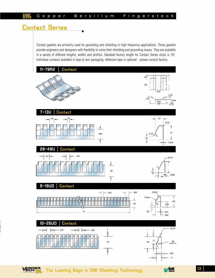
Contact gaskets are primarily used for grounding and shielding in high frequency applications. These gaskets provide engineers and designers with flexibility to solve their shielding and grounding issues. They are available in a variety of different lengths, widths and profiles. Standard factory length for Contact Series strips is 16". Individual contacts available in tape & reel packaging. Adhesive tape is optional - please consult factory.
11-78R2 Contact
9-19UD Contact
7-13U Contact
.04 .02 .07
R.04
R.02
.13
.03
0.004
.187
140
.250
.250
.780
0.03
.12R(4 PLCS)
.0045.125
.075
.22
10-26UD Contact
.187
28-49U Contact
.06 IR
.0063
.12
.28
Contact Series
.004
.090
.125
.38
.050
.130
.040 .060
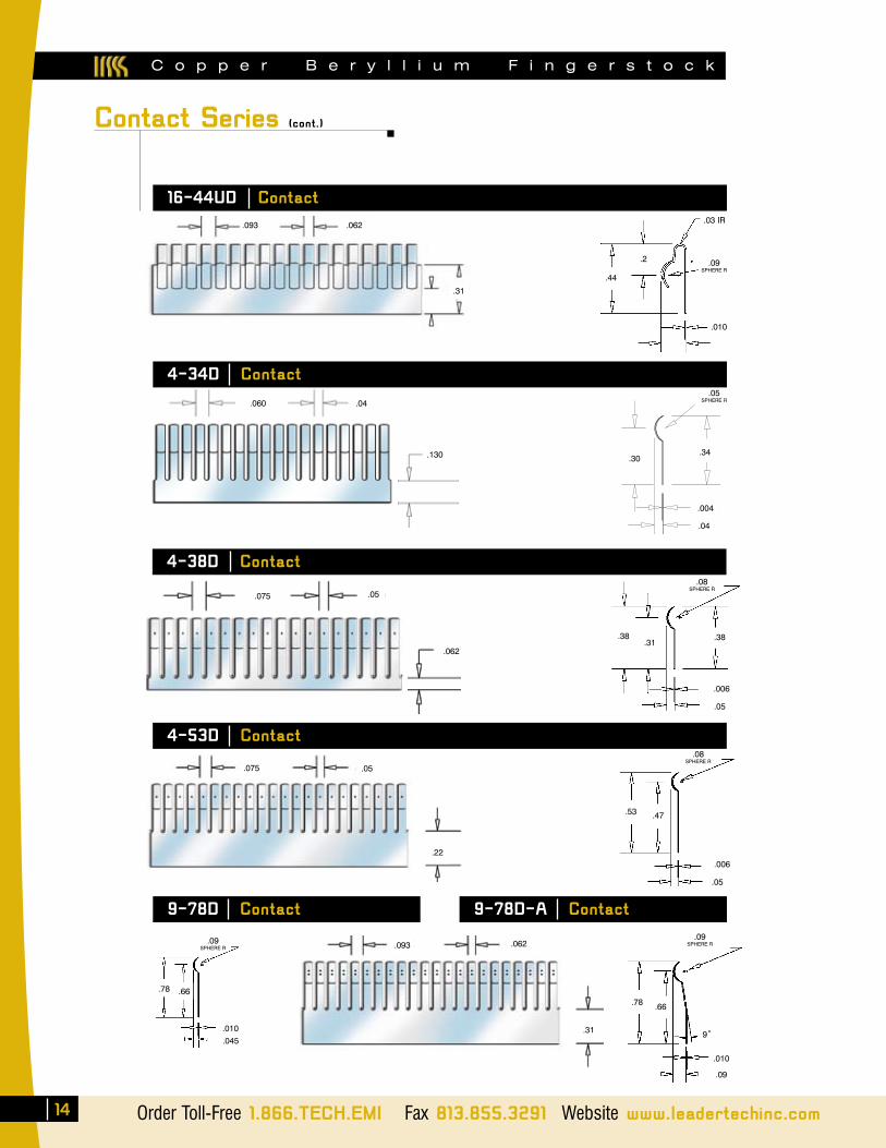
C o p p e r B e r y l l i u m F i n g e r s t o c k
14 Order Toll-Free 1.866.TECH.EMI Fax 813.855.3291 Website www.leadertechinc.com
.093 .062
.31
.09SPHERE R
.78 .66
.010
.045
9-78D Contact 9-78D-A Contact
.09SPHERE R
.78 .66
.010
.09
9˚
Contact Series (cont.)
.05 SPHERE R
.004
.05SPHERE R
.04
.30 .34
4-34D Contact
.130
.04.060
.03 IR
.010
.44
.2
.093 .062
.31
16-44UD Contact
.09SPHERE R
.38
.08SPHERE R
.05
.006
.38 .31
.075
4-38D Contact
.05
.062
.075 .05
.22
.08SPHERE R
.05
.006
.53 .47
4-53D Contact
C o p p e r B e r y l l i u m F i n g e r s t o c k
The Leading Edge in EMI Shielding Technology ✔RoHSCOMPLIANT
15
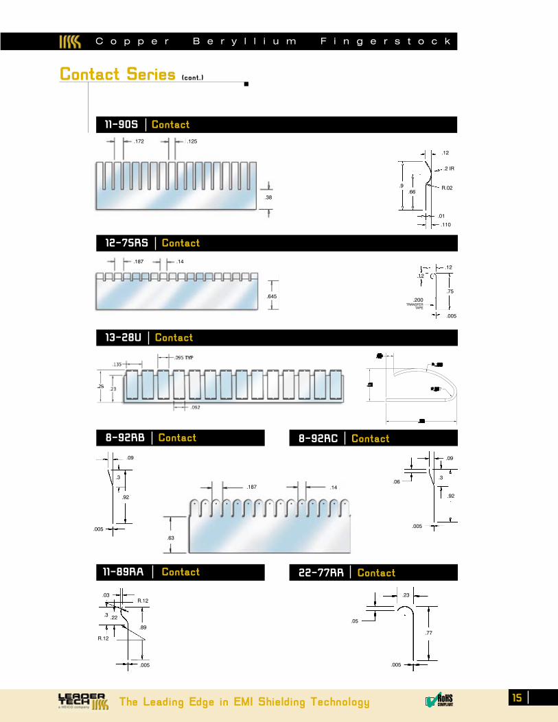
Contact Series (cont.)
.172 .125
.38
.9 .66
.12
.2 IR
R.02
.01
.110
11-90S Contact
12-75RS Contact
.645
.12
.12
.75
.005
.200TRANSFER
TAPE
.187 .14
.77
.05
.23
.005
8-92RB Contact
.09
.3
.92
.005
22-77RR Contact11-89RA Contact
.187 .14
.63
8-92RC Contact
.005
.92
.3.06
.09
.005
R.12 .03
.22
R.12
.3
.89
13-28U Contact
C o p p e r B e r y l l i u m F i n g e r s t o c k
Order Toll-Free 1.866.TECH.EMI Fax 813.855.3291 Website www.leadertechinc.com
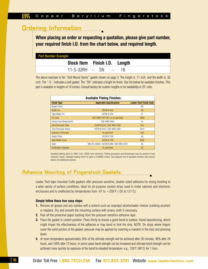
When placing an order or requesting a quotation, please give part number, your required finish I.D. from the chart below, and required length.
Leader Tech tape mounted CuBe gaskets offer pressure-sensitive, double-sided adhesive for strong bonding to a wide variety of surface conditions. Ideal for all-purpose contact strips used in metal cabinets and electronic enclosures and is unaffected by temperatures from -67 to +250°F (-55 to 121°C)
Simply follow these four easy steps:1. Remove all grease and oily residue with a solvent such as isopropyl alcohol/water mixture (rubbing alcohol)
or heptane. Dry and smooth the mounting surface with emery cloth if necessary.2. Peal off the protective paper backing from the pressure sensitive adhesive tape.3. Place the gasket in correct position. Press firmly to ensure a good bond to surface. Avoid repositioning, which
might impair the effectiveness of the adhesive or may bend or kink the strip. NOTE: On strips where fingers cover the solid portion of the gasket, pressure may be applied by inserting a mandrel in the strip and pressing down.
4. At room temperature approximately 50% of the ultimate strength will be achieved after 20 minutes, 90% after 24 hours, and 100% after 72 hours. In some cases bond strength can be increased and ultimate bond strength can be achieved more quickly by exposure of the bond to elevated temperature, e.g., 150°F (66°C) for 1 hour.
Adhesive Mounting of Fingerstock Gaskets
The above example is the “Slot Mount Series” gasket shown on page 3. The height is .11 inch and the width is .32 inch. The “-S-” indicates a soft gasket. The “SN” indicates a bright tin finish. See list below for available finishes. This part is available in lengths of 16 inches. Consult factory for custom lengths or for availability in 25’ coils.
Part Number Example:
Stock Item Finish I.D. Length11-S-32RH – SN – 16
Standard plating finish is .0001 inch (.0025 mm) minimum. Plating processes and thicknesses may be varied to meet customer needs. Standard plating finish for gold is 0.00005 inches. See adjacent list of available finishes and consult factory for additional options.
Ordering Information
16
Available Plating Finishes:
Finish Type Applicable Specifications Leader Tech Finish Code
Bright Finish - BD
Bright Tin ASTM B-545 SN
Satin/Matte Tin ASTM B-545 ST
Tin Lead SAE AMS-P-81728 / or as specified SNpb
Electro-less Nickel RoHS SAE AMS 2404 NI
Zinc/Chromate Clear ASTM B-633 / SAE AMS 2402 Zinc
Zinc/Chromate Yellow ASTM B-633 / SAE AMS 2402 ZincY
Cadmium Chromate As specified CdC
Bright Silver ASTM B-700 AG
Satin/Matte Silver ASTM B-700 MAG
Gold MIL-DTL-45204 / ASTM B-488 / SAE AMS 2422 AU
Solderable Unplated As specified SU
Order Toll-Free 1.866.TECH.EMI Fax 813.855.3291 Website www.leadertechinc.com
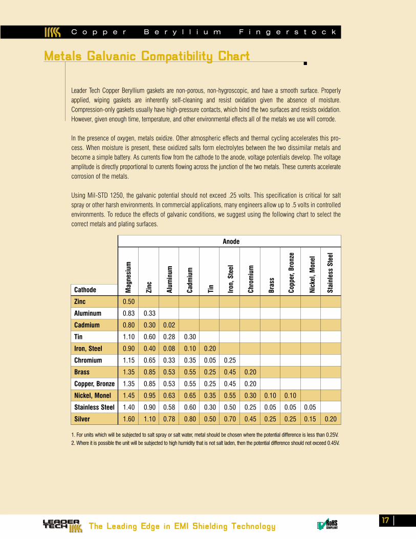
Leader Tech Copper Beryllium gaskets are non-porous, non-hygroscopic, and have a smooth surface. Properly applied, wiping gaskets are inherently self-cleaning and resist oxidation given the absence of moisture. Compression-only gaskets usually have high-pressure contacts, which bind the two surfaces and resists oxidation. However, given enough time, temperature, and other environmental effects all of the metals we use will corrode.
In the presence of oxygen, metals oxidize. Other atmospheric effects and thermal cycling accelerates this pro-cess. When moisture is present, these oxidized salts form electrolytes between the two dissimilar metals and become a simple battery. As currents flow from the cathode to the anode, voltage potentials develop. The voltage amplitude is directly proportional to currents flowing across the junction of the two metals. These currents accelerate corrosion of the metals.
Using Mil-STD 1250, the galvanic potential should not exceed .25 volts. This specification is critical for salt spray or other harsh environments. In commercial applications, many engineers allow up to .5 volts in controlled environments. To reduce the effects of galvanic conditions, we suggest using the following chart to select the correct metals and plating surfaces.
Cathode
Zinc 0.50
Aluminum 0.83 0.33
Cadmium 0.80 0.30 0.02
Tin 1.10 0.60 0.28 0.30
Iron, Steel 0.90 0.40 0.08 0.10 0.20
Chromium 1.15 0.65 0.33 0.35 0.05 0.25
Brass 1.35 0.85 0.53 0.55 0.25 0.45 0.20
Copper, Bronze 1.35 0.85 0.53 0.55 0.25 0.45 0.20
Nickel, Monel 1.45 0.95 0.63 0.65 0.35 0.55 0.30 0.10 0.10
Stainless Steel 1.40 0.90 0.58 0.60 0.30 0.50 0.25 0.05 0.05 0.05
Silver 1.60 1.10 0.78 0.80 0.50 0.70 0.45 0.25 0.25 0.15 0.20
Anode
Mag
nesi
um
Zinc
Alum
inum
Cadm
ium
Tin
Iron
, Ste
el
Chro
miu
m
Bras
s
Copp
er, B
ronz
e
Nick
el, M
onel
Stai
nles
s St
eel
1. For units which will be subjected to salt spray or salt water, metal should be chosen where the potential difference is less than 0.25V.
2. Where it is possible the unit will be subjected to high humidity that is not salt laden, then the potential difference should not exceed 0.45V.
C o p p e r B e r y l l i u m F i n g e r s t o c k
Metals Galvanic Compatibility Chart
The Leading Edge in EMI Shielding Technology ✔RoHSCOMPLIANT
17
C o p p e r B e r y l l i u m F i n g e r s t o c k
Order Toll-Free 1.866.TECH.EMI Fax 813.855.3291 Website www.leadertechinc.com
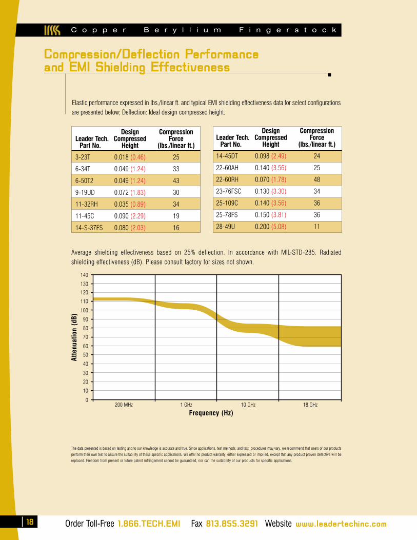
Elastic performance expressed in lbs./linear ft. and typical EMI shielding effectiveness data for select configurations are presented below; Deflection: Ideal design compressed height.
Design Compression Leader Tech. Compressed Force Part No. Height (lbs./linear ft.) 3-23T 0.018 (0.46) 25
6-34T 0.049 (1.24) 33
6-50T2 0.049 (1.24) 43
9-19UD 0.072 (1.83) 30
11-32RH 0.035 (0.89) 34
11-45C 0.090 (2.29) 19
14-S-37FS 0.080 (2.03) 16
Average shielding effectiveness based on 25% deflection. In accordance with MIL-STD-285. Radiated shielding effectiveness (dB). Please consult factory for sizes not shown.
The data presented is based on testing and to our knowledge is accurate and true. Since applications, test methods, and test procedures may vary, we recommend that users of our products
perform their own test to assure the suitability of these specific applications. We offer no product warranty, either expressed or implied, except that any product proven defective will be
replaced. Freedom from present or future patent infringement cannot be guaranteed, nor can the suitability of our products for specific applications.
Atte
nuat
ion
(dB)
140
130
120
110
100
90
80
70
60
50
40
30
20
10
0200 MHz 1 GHz 10 GHz 18 GHz
Frequency (Hz)
Design Compression Leader Tech. Compressed Force Part No. Height (lbs./linear ft.) 14-45DT 0.098 (2.49) 24
22-60AH 0.140 (3.56) 25
22-60RH 0.070 (1.78) 48
23-76FSC 0.130 (3.30) 34
25-109C 0.140 (3.56) 36
25-78FS 0.150 (3.81) 36
28-49U 0.200 (5.08) 11
Compression/Deflection Performanceand EMI Shielding Effectiveness
18
The Leading Edge in EMI Shielding Technology ✔RoHSCOMPLIANTOrder Toll-Free 1.866.TECH.EMI Fax 813.855.3291 Website www.leadertechinc.com
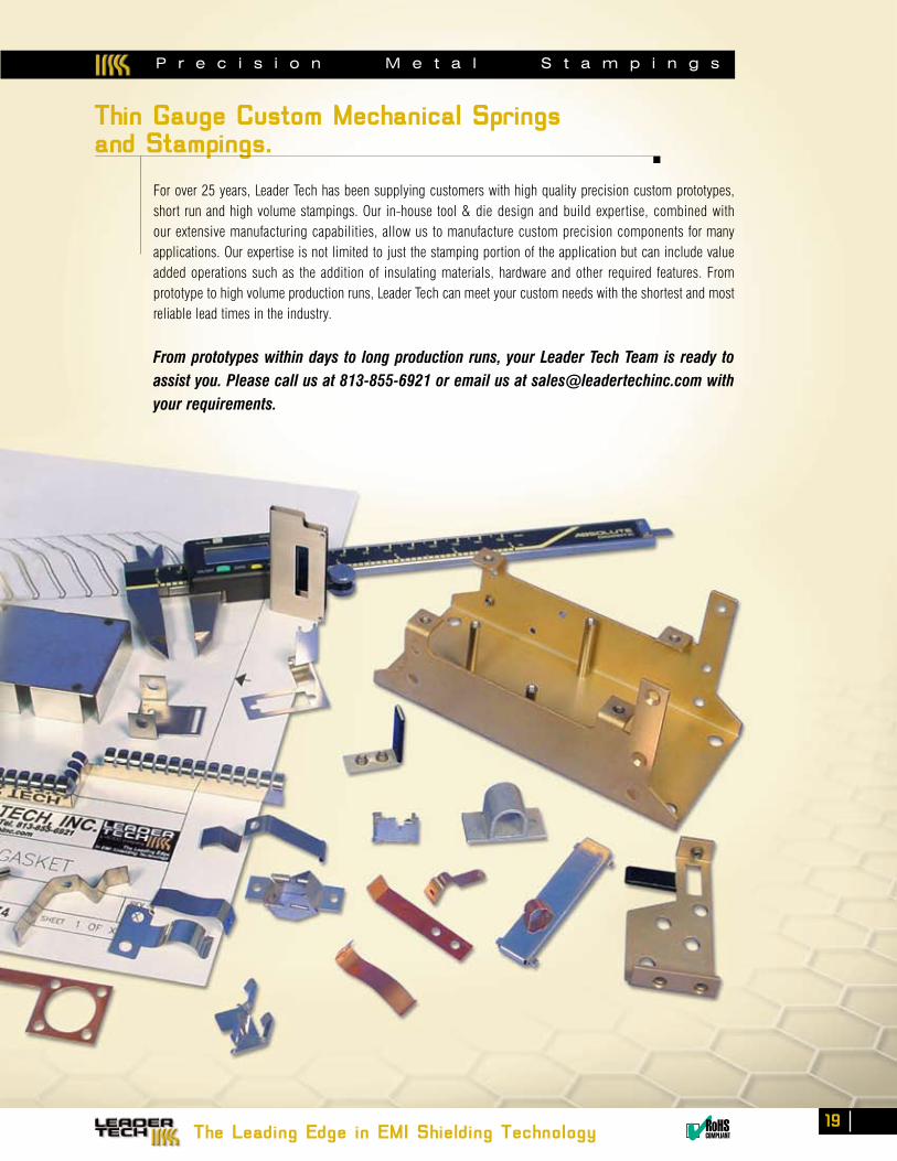
For over 25 years, Leader Tech has been supplying customers with high quality precision custom prototypes, short run and high volume stampings. Our in-house tool & die design and build expertise, combined with our extensive manufacturing capabilities, allow us to manufacture custom precision components for many applications. Our expertise is not limited to just the stamping portion of the application but can include value added operations such as the addition of insulating materials, hardware and other required features. From prototype to high volume production runs, Leader Tech can meet your custom needs with the shortest and most reliable lead times in the industry.
From prototypes within days to long production runs, your Leader Tech Team is ready to assist you. Please call us at 813-855-6921 or email us at [email protected] with your requirements.
P r e c i s i o n M e t a l S t a m p i n g s
Thin Gauge Custom Mechanical Springsand Stampings.
The Leading Edge in EMI Shielding Technology ✔RoHSCOMPLIANT
519
Order Toll-Free 1.866.TECH.EMI Fax 813.855.3291 Website www.leadertechinc.com
C o n d u c t i v e E l a s t o m e r S e r i e s
20
Profile Style Sheet Size Material Code If Conductive Adhesive
TechSIL
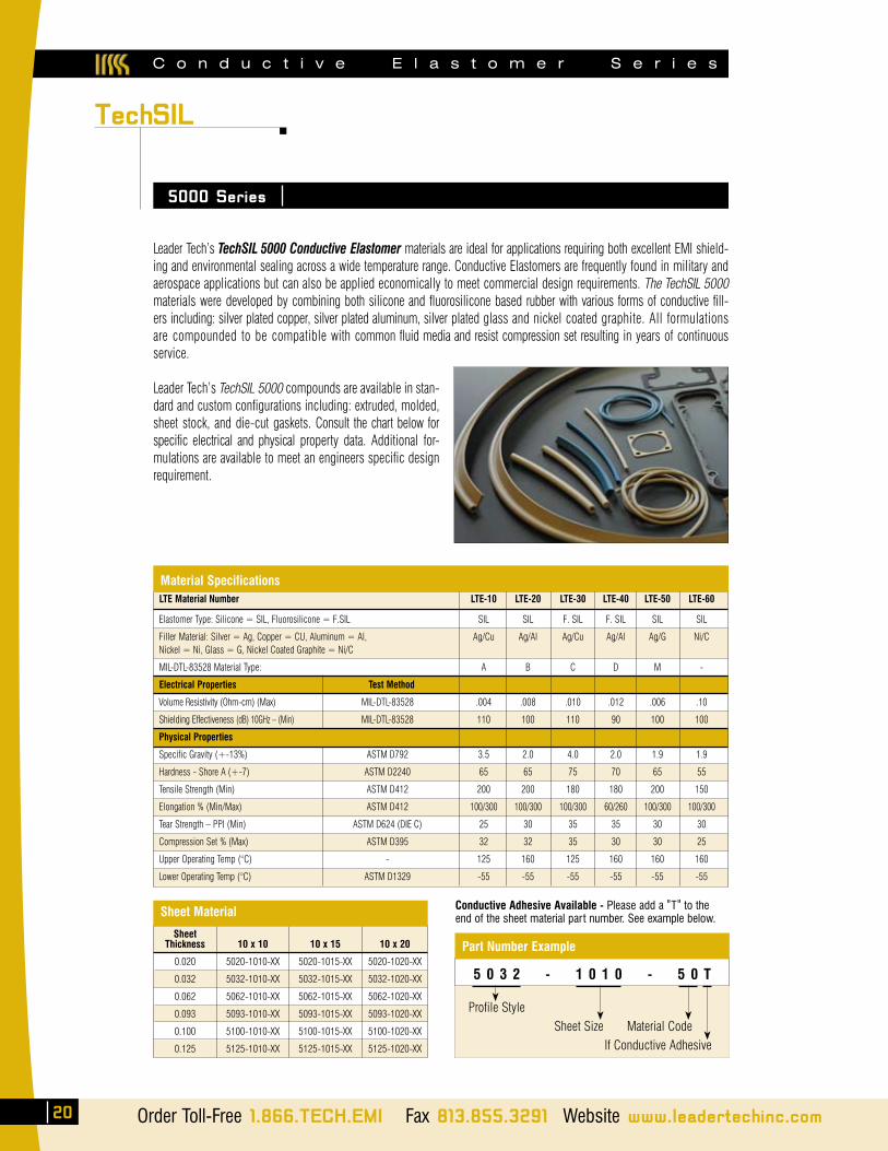
LTE Material Number LTE-10 LTE-20 LTE-30 LTE-40 LTE-50 LTE-60
Elastomer Type: Silicone = SIL, Fluorosilicone = F.SIL SIL SIL F. SIL F. SIL SIL SIL
Filler Material: Silver = Ag, Copper = CU, Aluminum = Al, Ag/Cu Ag/Al Ag/Cu Ag/Al Ag/G Ni/C Nickel = Ni, Glass = G, Nickel Coated Graphite = Ni/C
MIL-DTL-83528 Material Type: A B C D M -
Electrical Properties Test Method
Volume Resistivity (Ohm-cm) (Max) MIL-DTL-83528 .004 .008 .010 .012 .006 .10
Shielding Effectiveness (dB) 10GHz – (Min) MIL-DTL-83528 110 100 110 90 100 100
Physical Properties
Specific Gravity (+-13%) ASTM D792 3.5 2.0 4.0 2.0 1.9 1.9
Hardness - Shore A (+-7) ASTM D2240 65 65 75 70 65 55
Tensile Strength (Min) ASTM D412 200 200 180 180 200 150
Elongation % (Min/Max) ASTM D412 100/300 100/300 100/300 60/260 100/300 100/300
Tear Strength – PPI (Min) ASTM D624 (DIE C) 25 30 35 35 30 30
Compression Set % (Max) ASTM D395 32 32 35 30 30 25
Upper Operating Temp (°C) - 125 160 125 160 160 160
Lower Operating Temp (°C) ASTM D1329 -55 -55 -55 -55 -55 -55
SheetThickness
0.020
0.032
0.062
0.093
0.100
0.125
10 x 10
5020-1010-XX
5032-1010-XX
5062-1010-XX
5093-1010-XX
5100-1010-XX
5125-1010-XX
10 x 15
5020-1015-XX
5032-1015-XX
5062-1015-XX
5093-1015-XX
5100-1015-XX
5125-1015-XX
10 x 20
5020-1020-XX
5032-1020-XX
5062-1020-XX
5093-1020-XX
5100-1020-XX
5125-1020-XX
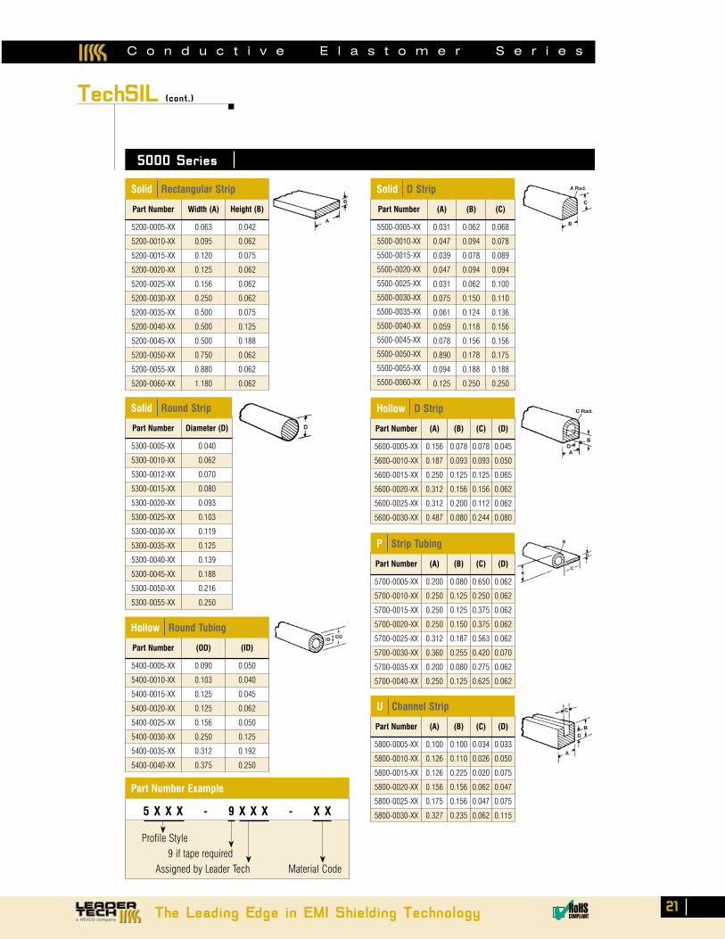
Leader Tech’s TechSIL 5000 Conductive Elastomer materials are ideal for applications requiring both excellent EMI shield-ing and environmental sealing across a wide temperature range. Conductive Elastomers are frequently found in military and aerospace applications but can also be applied economically to meet commercial design requirements. The TechSIL 5000 materials were developed by combining both silicone and fluorosilicone based rubber with various forms of conductive fill-ers including: silver plated copper, silver plated aluminum, silver plated glass and nickel coated graphite. All formulations are compounded to be compatible with common fluid media and resist compression set resulting in years of continuous service.
Leader Tech’s TechSIL 5000 compounds are available in stan-dard and custom configurations including: extruded, molded, sheet stock, and die-cut gaskets. Consult the chart below for specific electrical and physical property data. Additional for-mulations are available to meet an engineers specific design requirement.
5000 Series
Material Specifications
Sheet Material Conductive Adhesive Available - Please add a "T" to the end of the sheet material part number. See example below.
5 0 3 2 - 1 0 1 0 - 5 0 T
Part Number Example
The Leading Edge in EMI Shielding Technology ✔RoHSCOMPLIANT
21
Profile Style 9 if tape required Assigned by Leader Tech Material Code
TechSIL (cont.)
5000 Series
Part Number
5200-0005-XX
5200-0010-XX
5200-0015-XX
5200-0020-XX
5200-0025-XX
5200-0030-XX
5200-0035-XX
5200-0040-XX
5200-0045-XX
5200-0050-XX
5200-0055-XX
5200-0060-XX
Width (A)
0.063
0.095
0.120
0.125
0.156
0.250
0.500
0.500
0.500
0.750
0.880
1.180
Height (B)
0.042
0.062
0.075
0.062
0.062
0.062
0.075
0.125
0.188
0.062
0.062
0.062
Part Number
5500-0005-XX
5500-0010-XX
5500-0015-XX
5500-0020-XX
5500-0025-XX
5500-0030-XX
5500-0035-XX
5500-0040-XX
5500-0045-XX
5500-0050-XX
5500-0055-XX
5500-0060-XX
(A)
0.031
0.047
0.039
0.047
0.031
0.075
0.061
0.059
0.078
0.890
0.094
0.125
(B)
0.062
0.094
0.078
0.094
0.062
0.150
0.124
0.118
0.156
0.178
0.188
0.250
Part Number
5400-0005-XX
5400-0010-XX
5400-0015-XX
5400-0020-XX
5400-0025-XX
5400-0030-XX
5400-0035-XX
5400-0040-XX
(OD)
0.090
0.103
0.125
0.125
0.156
0.250
0.312
0.375
(ID)
0.050
0.040
0.045
0.062
0.050
0.125
0.192
0.250
(C)
0.068
0.078
0.089
0.094
0.100
0.110
0.136
0.156
0.156
0.175
0.188
0.250
Part Number
5600-0005-XX
5600-0010-XX
5600-0015-XX
5600-0020-XX
5600-0025-XX
5600-0030-XX
(A)
0.156
0.187
0.250
0.312
0.312
0.487
(B)
0.078
0.093
0.125
0.156
0.200
0.080
(C)
0.078
0.093
0.125
0.156
0.112
0.244
(D)
0.045
0.050
0.065
0.062
0.062
0.080
Part Number
5700-0005-XX
5700-0010-XX
5700-0015-XX
5700-0020-XX
5700-0025-XX
5700-0030-XX
5700-0035-XX
5700-0040-XX
(A)
0.200
0.250
0.250
0.250
0.312
0.360
0.200
0.250
(B)
0.080
0.125
0.125
0.150
0.187
0.255
0.080
0.125
(C)
0.650
0.250
0.375
0.375
0.563
0.420
0.275
0.625
(D)
0.062
0.062
0.062
0.062
0.062
0.070
0.062
0.062
Part Number
5800-0005-XX
5800-0010-XX
5800-0015-XX
5800-0020-XX
5800-0025-XX
5800-0030-XX
(A)
0.100
0.126
0.126
0.156
0.175
0.327
(B)
0.100
0.110
0.225
0.156
0.156
0.235
(C)
0.034
0.026
0.020
0.062
0.047
0.062
(D)
0.033
0.050
0.075
0.047
0.075
0.115
Solid Rectangular Strip
Hollow D Strip
Solid D Strip
P Strip Tubing
U Channel Strip
Hollow Round Tubing
C o n d u c t i v e E l a s t o m e r S e r i e s
Part Number
5300-0005-XX
5300-0010-XX
5300-0012-XX
5300-0015-XX
5300-0020-XX
5300-0025-XX
5300-0030-XX
5300-0035-XX
5300-0040-XX
5300-0045-XX
5300-0050-XX
5300-0055-XX
Diameter (D)
0.040
0.062
0.070
0.080
0.093
0.103
0.119
0.125
0.139
0.188
0.216
0.250
Solid Round Strip
5 X X X - 9 X X X - X X
Part Number Example

O r i e n t e d W i r e S e r i e s
22 Order Toll-Free 1.866.TECH.EMI Fax 813.855.3291 Website www.leadertechinc.com
TechSIL (cont.)
Leader Tech’s TechSIL 8000 Oriented Wire gasketing is designed for use in suppressing EMI/RFI up to 100 dB in the E-Field/up to 50 dB in the H-Field, while offering an effective environmental seal between mating surfaces. This material is comprised of monel or aluminum wire oriented perpendicular to the mating surfaces and embedded in solid or sponge silicone elastomer. The wires are crimped for additional resiliency and to optimize the mechanical perfor-mance of the gasket. The silicone based TechSIL has 700-900 wires per sq./in. and is capable of withstanding temperatures from -80° to a maximum of 500° F (-62° to 260°C). TechSIL Oriented Wire materials are available in strip or sheet form and can easily be die cut into complex shapes or fabricated into custom frame gaskets. All TechSIL 8000 materials meet the DESC drawing 90046.
8000 Series
*0.032" thickness is only available in Silicone Solid
H
W
All materials available with tape.The data presented is accurate and true to our knowledge. Since
applications, test methods and test procedures may vary, we recommend
that users perform their own tests to assure suitability for specific appli-
cations. We offer no product warranty, either expressed or implied,
except we will replace any product found to be defective.
Part Number
8100-0005-XX
8100-0010-XX
8100-0015-XX
8100-0020-XX
8100-0025-XX
8100-0030-XX
8100-0035-XX
8100-0040-XX
8100-0045-XX
8100-0050-XX
8100-0055-XX
8100-0060-XX
8100-0065-XX
8100-0070-XX
8100-0075-XX
8100-0080-XX
8100-0085-XX
8100-0090-XX
Height
0.032* (0.81)
0.032* (0.81)
0.032* (0.81)
0.062 (1.57)
0.062 (1.57)
0.062 (1.57)
0.093 (2.36)
0.093 (2.36)
0.093 (2.36)
0.125 (3.18)
0.125 (3.18)
0.125 (3.18)
0.188 (4.78)
0.188 (4.78)
0.188 (4.78)
0.250 (6.35)
0.250 (6.35)
0.250 (6.35)
Width
3.00 (76.20)
4.50 (114.30)
6.00 (152.40)
3.00 (76.20)
4.50 (114.30)
6.00 (152.40)
3.00 (76.20)
4.50 (114.30)
6.00 (152.40)
3.00 (76.20)
4.50 (114.30)
6.00 (152.40)
3.00 (76.20)
4.50 (114.30)
6.00 (152.40)
3.00 (76.20)
4.50 (114.30)
6.00 (152.40)
TechSIL® Sheet
Part Number
8200-0005-XX
8200-0010-XX
8200-0015-XX
8200-0020-XX
8200-0025-XX
8200-0030-XX
8200-0035-XX
8200-0040-XX
8200-0045-XX
8200-0050-XX
8200-0055-XX
8200-0060-XX
8200-0065-XX
8200-0070-XX
8200-0075-XX
8200-0080-XX
8200-0085-XX
8200-0090-XX
8200-0095-XX
8200-0100-XX
8200-0105-XX
8200-0110-XX
8200-0115-XX
8200-0120-XX
Height
0.062 (1.57)
0.062 (1.57)
0.062 (1.57)
0.062 (1.57)
0.062 (1.57)
0.062 (1.57)
0.093 (2.36)
0.093 (2.36)
0.093 (2.36)
0.093 (2.36)
0.093 (2.36)
0.093 (2.36)
0.125 (3.18)
0.125 (3.18)
0.125 (3.18)
0.125 (3.18)
0.125 (3.18)
0.188 (4.78)
0.188 (4.78)
0.188 (4.78)
0.188 (4.78)
0.250 (6.35)
0.250 (6.35)
0.250 (6.35)
Width
0.093 (2.36)
0.125 (2.36)
0.188 (4.78)
0.250 (6.35)
0.375 (9.53)
0.500 (12.70)
0.093 (2.36)
0.125 (2.36)
0.188 (4.78)
0.250 (6.35)
0.375 (9.53)
0.500 (12.70)
0.125 (2.36)
0.188 (4.78)
0.250 (6.35)
0.375 (9.53)
0.500 (12.70)
0.188 (4.78)
0.250 (6.35)
0.375 (9.53)
0.500 (12.70)
0.250 (6.35)
0.375 (9.53)
0.500 (12.70)
TechSIL® Strip
H
W
Profile Style 9 if tape requiredAssigned by Leader Tech Material Code
8 X X X - 9 X X X - X X
Part Number Example
Black = inches Red= mm
Material Code
81
-82
-83
-84
Wire Specification
Monel Wire - 0.0045 Dia. (0.10)Per QQ-N-281
Monel Wire - 0.0045 Dia. (0.10)Per QQ-N-281
Aluminum Wire - 0.005 Dia.(0.13) Alloy 5056
Aluminum Wire - 0.005 Dia.(0.13) Alloy 5056
Elastomer
Silicone SpongePer AMS 3195
Silicone SolidZZR765, Class 2B, Grade40
Silicone SpongePer AMS 3195
Silicone SolidZZR765, Class 2B, Grade 40
The Leading Edge in EMI Shielding Technology ✔RoHSCOMPLIANT
23
Profile Style 9 if tape requiredAssigned by Leader Tech Material Code
TechMESH
Knitted Wire
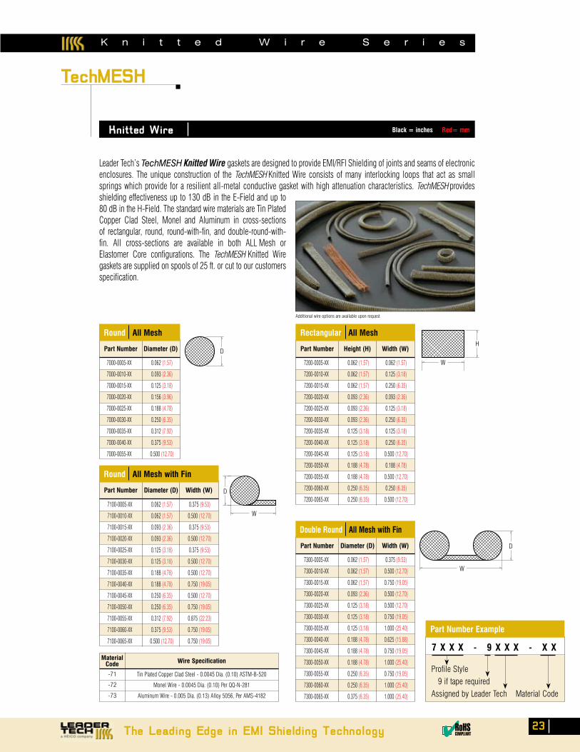
Leader Tech’s TechMESH Knitted Wire gaskets are designed to provide EMI/RFI Shielding of joints and seams of electronic enclosures. The unique construction of the TechMESH Knitted Wire consists of many interlocking loops that act as small springs which provide for a resilient all-metal conductive gasket with high attenuation characteristics. TechMESH provides shielding effectiveness up to 130 dB in the E-Field and up to 80 dB in the H-Field. The standard wire materials are Tin Plated Copper Clad Steel, Monel and Aluminum in cross-sections of rectangular, round, round-with-fin, and double-round-with-fin. All cross-sections are available in both ALL Mesh or Elastomer Core configurations. The TechMESH Knitted Wire gaskets are supplied on spools of 25 ft. or cut to our customers specification.
Additional wire options are available upon request
Part Number Diameter (D)
Round All Mesh
Part Number Height (H) Width (W)
Rectangular All Mesh
Part Number Diameter (D) Width (W)
Double Round All Mesh with Fin
MaterialCode
-71
-72
-73
Wire Specification
Tin Plated Copper Clad Steel - 0.0045 Dia. (0.10) ASTM-B-520
Monel Wire - 0.0045 Dia. (0.10) Per QQ-N-281
Aluminum Wire - 0.005 Dia. (0.13) Alloy 5056, Per AMS-4182
Part Number Diameter (D) Width (W)
Round All Mesh with Fin
H
W
D
D
W
W
H
7000-0005-XX 0.062 (1.57)
7000-0010-XX 0.093 (2.36)
7000-0015-XX 0.125 (3.18)
7000-0020-XX 0.156 (3.96)
7000-0025-XX 0.188 (4.78)
7000-0030-XX 0.250 (6.35)
7000-0035-XX 0.312 (7.92)
7000-0040-XX 0.375 (9.53)
7000-0055-XX 0.500 (12.70)
7200-0005-XX 0.062 (1.57) 0.062 (1.57)
7200-0010-XX 0.062 (1.57) 0.125 (3.18)
7200-0015-XX 0.062 (1.57) 0.250 (6.35)
7200-0020-XX 0.093 (2.36) 0.093 (2.36)
7200-0025-XX 0.093 (2.36) 0.125 (3.18)
7200-0030-XX 0.093 (2.36) 0.250 (6.35)
7200-0035-XX 0.125 (3.18) 0.125 (3.18)
7200-0040-XX 0.125 (3.18) 0.250 (6.35)
7200-0045-XX 0.125 (3.18) 0.500 (12.70)
7200-0050-XX 0.188 (4.78) 0.188 (4.78)
7200-0055-XX 0.188 (4.78) 0.500 (12.70)
7200-0060-XX 0.250 (6.35) 0.250 (6.35)
7200-0065-XX 0.250 (6.35) 0.500 (12.70)
7300-0005-XX 0.062 (1.57) 0.375 (9.53)
7300-0010-XX 0.062 (1.57) 0.500 (12.70)
7300-0015-XX 0.062 (1.57) 0.750 (19.05)
7300-0020-XX 0.093 (2.36) 0.500 (12.70)
7300-0025-XX 0.125 (3.18) 0.500 (12.70)
7300-0030-XX 0.125 (3.18) 0.750 (19.05)
7300-0035-XX 0.125 (3.18) 1.000 (25.40)
7300-0040-XX 0.188 (4.78) 0.625 (15.88)
7300-0045-XX 0.188 (4.78) 0.750 (19.05)
7300-0050-XX 0.188 (4.78) 1.000 (25.40)
7300-0055-XX 0.250 (6.35) 0.750 (19.05)
7300-0060-XX 0.250 (6.35) 1.000 (25.40)
7300-0065-XX 0.375 (6.35) 1.000 (25.40)
7100-0005-XX 0.062 (1.57) 0.375 (9.53)
7100-0010-XX 0.062 (1.57) 0.500 (12.70)
7100-0015-XX 0.093 (2.36) 0.375 (9.53)
7100-0020-XX 0.093 (2.36) 0.500 (12.70)
7100-0025-XX 0.125 (3.18) 0.375 (9.53)
7100-0030-XX 0.125 (3.18) 0.500 (12.70)
7100-0035-XX 0.188 (4.78) 0.500 (12.70)
7100-0040-XX 0.188 (4.78) 0.750 (19.05)
7100-0045-XX 0.250 (6.35) 0.500 (12.70)
7100-0050-XX 0.250 (6.35) 0.750 (19.05)
7100-0055-XX 0.312 (7.92) 0.875 (22.23)
7100-0060-XX 0.375 (9.53) 0.750 (19.05)
7100-0065-XX 0.500 (12.70) 0.750 (19.05)
K n i t t e d W i r e S e r i e s
7 X X X - 9 X X X - X X
Part Number Example
Black = inches Red= mm
D
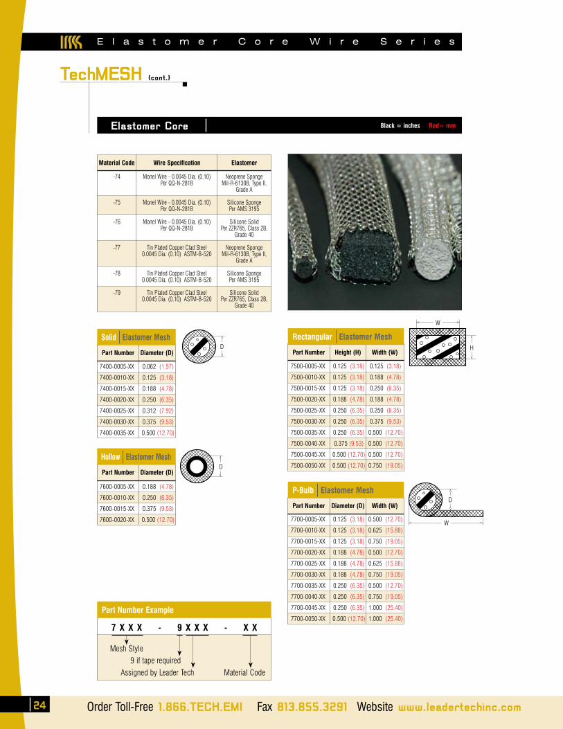
E l a s t o m e r C o r e W i r e S e r i e s
TechMESH (cont.)
Elastomer Core
Part Number Height (H) Width (W)
Rectangular Elastomer Mesh
Part Number Diameter (D)
Solid Elastomer Mesh
Material Code
-74
-75
-76
-77
-78
-79
Wire Specification
Monel Wire - 0.0045 Dia. (0.10)Per QQ-N-281B
Monel Wire - 0.0045 Dia. (0.10)
Per QQ-N-281B
Monel Wire - 0.0045 Dia. (0.10)Per QQ-N-281B
Tin Plated Copper Clad Steel
0.0045 Dia. (0.10) ASTM-B-520
Tin Plated Copper Clad Steel0.0045 Dia. (0.10) ASTM-B-520
Tin Plated Copper Clad Steel0.0045 Dia. (0.10) ASTM-B-520
Elastomer
Neoprene Sponge Mil-R-6130B, Type II,
Grade A
Silicone SpongePer AMS 3195
Silicone SolidPer ZZR765, Class 2B,
Grade 40
Neoprene Sponge Mil-R-6130B, Type II,
Grade A
Silicone SpongePer AMS 3195
Silicone Solid
Per ZZR765, Class 2B, Grade 40
Part Number Diameter (D) Width (W)
P-Bulb Elastomer Mesh
Part Number Diameter (D)
Hollow Elastomer Mesh
D
D
D
W
H
W
7400-0005-XX 0.062 (1.57)
7400-0010-XX 0.125 (3.18)
7400-0015-XX 0.188 (4.78)
7400-0020-XX 0.250 (6.35)
7400-0025-XX 0.312 (7.92)
7400-0030-XX 0.375 (9.53)
7400-0035-XX 0.500 (12.70)
7500-0005-XX 0.125 (3.18) 0.125 (3.18)
7500-0010-XX 0.125 (3.18) 0.188 (4.78)
7500-0015-XX 0.125 (3.18) 0.250 (6.35)
7500-0020-XX 0.188 (4.78) 0.188 (4.78)
7500-0025-XX 0.250 (6.35) 0.250 (6.35)
7500-0030-XX 0.250 (6.35) 0.375 (9.53)
7500-0035-XX 0.250 (6.35) 0.500 (12.70)
7500-0040-XX 0.375 (9.53) 0.500 (12.70)
7500-0045-XX 0.500 (12.70) 0.500 (12.70)
7500-0050-XX 0.500 (12.70) 0.750 (19.05)
7600-0005-XX 0.188 (4.78)
7600-0010-XX 0.250 (6.35)
7600-0015-XX 0.375 (9.53)
7600-0020-XX 0.500 (12.70) 7700-0005-XX 0.125 (3.18) 0.500 (12.70)
7700-0010-XX 0.125 (3.18) 0.625 (15.88)
7700-0015-XX 0.125 (3.18) 0.750 (19.05)
7700-0020-XX 0.188 (4.78) 0.500 (12.70)
7700-0025-XX 0.188 (4.78) 0.625 (15.88)
7700-0030-XX 0.188 (4.78) 0.750 (19.05)
7700-0035-XX 0.250 (6.35) 0.500 (12.70)
7700-0040-XX 0.250 (6.35) 0.750 (19.05)
7700-0045-XX 0.250 (6.35) 1.000 (25.40)
7700-0050-XX 0.500 (12.70) 1.000 (25.40)
Mesh Style 9 if tape required Assigned by Leader Tech Material Code
Part Number Example
7 X X X - 9 X X X - X X
Black = inches Red= mm
24 Order Toll-Free 1.866.TECH.EMI Fax 813.855.3291 Website www.leadertechinc.com
TechMESH (cont.)
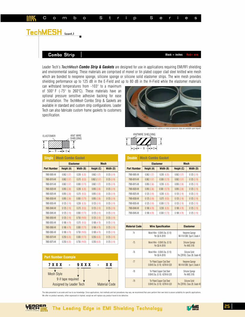
Combo Strip
Leader Tech’s TechMesh Combo Strip & Gaskets are designed for use in applications requiring EMI/RFI shielding and environmental sealing. These materials are comprised of monel or tin plated copper clad steel knitted wire mesh which are bonded to neoprene sponge, silicone sponge or silicone solid elastomer strips. The wire mesh provides shielding performance up to 125 dB in the E-Field and up to 80 dB in the H-Field while the elastomer materials can withstand temperatures from -103° to a maximum of 500° F (-75° to 260°C). These materials have an optional pressure sensitive adhesive backing for ease of installation. The TechMesh Combo Strip & Gaskets are available in standard and custom strip configurations. Leader Tech can also fabricate custom frame gaskets to customers specification.
Part Number
7800-0005-XX
7800-0010-XX
7800-0015-XX
7800-0020-XX
7800-0025-XX
7800-0030-XX
7800-0035-XX
7800-0040-XX
7800-0045-XX
7800-0050-XX
7800-0055-XX
7800-0060-XX
7800-0065-XX
7800-0070-XX
7800-0075-XX
Height (A)
0.062 (1.57)
0.062 (1.57)
0.062 (1.57)
0.093 (2.36)
0.093 (2.36)
0.093 (2.36)
0.125 (3.18)
0.125 (3.18)
0.125 (3.18)
0.125 (3.18)
0.188 (4.78)
0.188 (4.78)
0.188 (4.78)
0.250 (6.35)
0.250 (6.35)
Width (B)
0.250 (6.35)
0.375 (9.53)
0.500 (12.70)
0.250 (6.35)
0.375 (9.53)
0.500 (12.70)
0.250 (6.35)
0.375 (9.53)
0.500 (12.70)
0.750 (19.05)
0.375 (9.53)
0.500 (12.70)
0.750 (19.05)
0.500 (12.70)
0.750 (19.05)
Height (C)
0.062 (1.57)
0.062 ((1.57)
0.062 (1.57)
0.093 (2.36)
0.093 (2.36)
0.093 (2.36)
0.125 (3.18)
0.125 (3.18)
0.125 (3.18)
0.125 (3.18)
0.188 (4.78)
0.188 (4.78)
0.188 (4.78)
0.250 (6.35)
0.250 (6.35)
Width (D)
0.125 (3.18)
0.125 (3.18)
0.125 (3.18)
0.125 (3.18)
0.125 (3.18)
0.125 (3.18)
0.125 (3.18)
0.125 (3.18)
0.125 (3.18)
0.125 (3.18)
0.125 (3.18)
0.125 (3.18)
0.125 (3.18)
0.125 (3.18)
0.125 (3.18)
Single Mesh Combo Gasket
The data presented is accurate and true to our knowledge. Since applications, test methods and test procedures may vary, we recommend that users perform their own tests to assure suitability for specific applications.
We offer no product warranty, either expressed or implied, except we will replace any product found to be defective.
Additional wire options or metal compression stops are available upon request.
Mesh
Material Code-
74
-75
-76
-77
-78
-79
Wire Specification
Monel Wire - 0.0045 Dia. (0.10)Per QQ-N-281B
Monel Wire - 0.0045 Dia. (0.10)Per QQ-N-281B
Monel Wire - 0.0045 Dia. (0.10)Per QQ-N-281B
Tin Plated Copper Clad Steel0.0045 Dia. (0.10) ASTM-B-520
Tin Plated Copper Clad Steel0.0045 Dia. (0.10) ASTM-B-520
Tin Plated Copper Clad Steel0.0045 Dia. (0.10) ASTM-B-520
Elastomer
Neoprene Sponge Mil-R-6130B, Type II, Grade A
Silicone SpongePer AMS 3195
Silicone SolidPer ZZR765, Class 2B, Grade 40
Neoprene Sponge Mil-R-6130B, Type II, Grade A
Silicone SpongePer AMS 3195
Silicone SolidPer ZZR765, Class 2B, Grade 40
Elastomer
Part Number
7900-0005-XX
7900-0010-XX
7900-0015-XX
7900-0020-XX
7900-0025-XX
7900-0030-XX
7900-0035-XX
7900-0040-XX
7900-0045-XX
Height (A)
0.062 (1.57)
0.062 (1.57)
0.093 (2.36)
0.093 (2.36)
0.125 (3.18)
0.125 (3.18)
0.125 (3.18)
0.188 (4.78)
0.188 (4.78)
Width (B)
0.250 (6.35)
0.500 (12.70)
0.250 (6.35)
0.500 (12.70)
0.250 (6.35)
0.375 (9.53)
0.500 (12.70)
0.250 (6.35)
0.500 (12.70)
Height (C)
0.062 (1.57)
0.062 (1.57)
0.093 (2.36)
0.093 (2.36)
0.125 (3.18)
0.125 (3.18)
0.125 (3.18)
0.188 (4.78)
0.188 (4.78)
Width (D)
0.125 (3.18)
0.125 (3.18)
0.125 (3.18)
0.125 (3.18)
0.125 (3.18)
0.125 (3.18)
0.125 (3.18)
0.125 (3.18)
0.125 (3.18)
Double Mesh Combo Gasket
MeshElastomer
A
B
C
D
KNIT WIRESHIELDING
ELASTOMER
B
C
D
KNITWIRE SHIELDING
C
D
C o m b o S t r i p S e r i e s
Mesh Style 9 if tape required Assigned by Leader Tech Material Code
Part Number Example
7 X X X - 9 X X X - X X
Black = inches Red= mm
The Leading Edge in EMI Shielding Technology ✔RoHSCOMPLIANT
25
H o n e y c o m b P a n e l S e r i e s
TechVENT
Honeycomb Panel
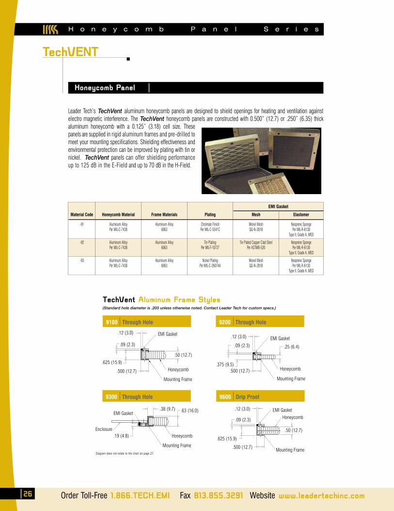
Leader Tech’s TechVent aluminum honeycomb panels are designed to shield openings for heating and ventilation against electro magnetic interference. The TechVent honeycomb panels are constructed with 0.500” (12.7) or .250” (6.35) thick aluminum honeycomb with a 0.125” (3.18) cell size. These panels are supplied in rigid aluminum frames and pre-drilled to meet your mounting specifications. Shielding effectiveness and environmental protection can be improved by plating with tin or nickel. TechVent panels can offer shielding performance up to 125 dB in the E-Field and up to 70 dB in the H-Field.
TechVent Aluminum Frame Styles (Standard hole diameter is .203 unless otherwise noted. Contact Leader Tech for custom specs.)
Material Code
-91
-92
-93
Honeycomb Material
Aluminum AlloyPer MIL-C-7438
Aluminum AlloyPer MIL-C-7438
Aluminum AlloyPer MIL-C-7438
Plating
Chromate FinishPer MIL-C-5541C
Tin PlatingPer MIL-T-10727
Nickel PlatingPer MIL-C-26074A
Mesh
Monel MeshQQ-N-281B
Tin Plated Copper Clad SteelPer ASTMB-520
Monel MeshQQ-N-281B
Elastomer
Neoprene SpongePer MIL-R-6130
Type II, Grade A, MED
Neoprene SpongePer MIL-R-6130
Type II, Grade A, MED
Neoprene SpongePer MIL-R-6130
Type II, Grade A, MED
EMI Gasket
Frame Materials
Aluminum Alloy6063
Aluminum Alloy6063
Aluminum Alloy6063
9100 Through Hole 9200 Through Hole
9300 Through Hole 9600 Drip Proof
.09 (2.3)
.12 (3.0)
.625 (15.9)
.500 (12.7)
EMI Gasket
.50 (12.7)
Honeycomb
Mounting Frame
EMI Gasket
.25 (6.4)
Honeycomb
Mounting Frame
.09 (2.3)
.375 (9.5).500 (12.7)
.12 (3.0)
.38 (9.7) .63 (16.0)
Honeycomb
Mounting Frame
.19 (4.8)Enclosure
EMI Gasket
Mounting Frame
Honeycomb
.50 (12.7)
EMI Gasket.12 (3.0)
.09 (2.3)
.625 (15.9)
.500 (12.7)
26 Order Toll-Free 1.866.TECH.EMI Fax 813.855.3291 Website www.leadertechinc.com
Diagram does not relate to the chart on page 27.
H o n e y c o m b P a n e l S e r i e s
TechVENT (cont.)
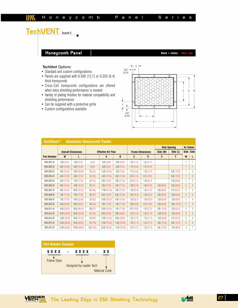
Honeycomb Panel
TechVent Options:• Standardandcustomconfigurations• Panelsaresuppliedwith0.500(12.7)or0.250(6.4)
thick honeycomb• Cross-Cell honeycomb configurations are offered
when extra shielding performance is needed• Variety of plating finishes for material compatibility and
shielding performance• Canbesuppliedwithaprotectivegrille• Customconfigurationsavailable
Part Number W L A
Effective Air FlowOverall Dimensions
B C D E F
Side (W)Frame Dimensions
Hole Spacing
Side (L)
No. Fasteners
TechVents® Aluminum Honeycomb Panels
Side
W
Side
L
9XXX-0001-XX 3.00 (76.20) 3.00 (76.20) 4 (26) 2.00 (50.80) 2.00 (50.80) 1.25 (31.75) 1.25 (31.75) 1 1
9XXX-0002-XX 4.00 (101.60) 4.00 (101.60) 9 (58) 3.00 (76.20) 3.00 (76.20) 1.75 (44.45) 1.75 (44.45) 1 1
9XXX-0003-XX 4.00 (101.60) 12.00 (304.80) 33 (213) 11.00 (279.40) 3.00 (76.20) 1.75 (44.45) 1.25 (31.75) 3.00 (76.20) 1 4
9XXX-0004-XX 5.00 (127.00) 5.00 (127.00) 16 (103) 4.00 (101.60) 4.00 (101.60) 2.25 (57.15) 0.75 (19.05) 3.00 (76.20) 1 2
9XXX-0005-XX 5.00 (127.00) 7.00 (177.80) 24 (155) 6.00 (152.40) 4.00 (101.60) 2.25 (57.15) 1.50 (38.10) 3.50 (88.90) 1 2
9XXX-0006-XX 6.00 (152.40) 6.00 (152.40) 25 (161) 5.00 (127.00) 5.00 (127.00) 1.00 (25.40) 1.00 (25.40) 3.50 (88.90) 3.50 (88.90) 2 2
9XXX-0007-XX 6.00 (152.40) 18.00 (457.20) 85 (548) 17.00 (431.80) 5.00 (127.00) 1.00 (25.40) 1.25 (31.75) 3.50 (88.90) 3.75 (95.25) 2 5
9XXX-0008-XX 7.00 (177.80) 7.00 (177.80) 36 (232) 6.00 (152.40) 6.00 (152.40) 1.50 (38.10) 1.50 (38.10) 3.50 (88.90) 3.50 (88.90) 2 2
9XXX-0009-XX 7.00 (177.80) 14.00 (355.60) 78 (503) 13.00 (330.20) 6.00 (152.40) 1.50 (38.10) 1.50 (38.10) 3.50 (88.90) 3.50 (88.90) 2 4
9XXX-0010-XX 8.00 (203.20) 8.00 (203.20) 49 (316) 7.00 (177.80) 7.00 (177.80) 2.00 (50.80) 0.75 (19.05) 3.50 (88.90) 3.00 (76.20) 2 3
9XXX-0011-XX 8.00 (203.20) 16.00 (406.40) 105 (677) 15.00 (381.00) 7.00 (177.80) 0.75 (19.05) 1.25 (31.75) 3.00 (76.20) 3.25 (82.55) 3 5
9XXX-0012-XX 10.00 (254.00) 10.00 (254.00) 81 (522) 9.00 (228.60) 9.00 (228.60) 1.25 (31.75) 1.25 (31.75) 3.50 (88.90) 3.50 (88.90) 3 3
9XXX-0013-XX 10.00 (254.00) 18.00 (457.20) 153 (987) 17.00 (431.80) 9.00 (228.60) 1.25 (31.75) 1.25 (31.75) 3.50 (88.90) 3.75 (95.25) 3 5
9XXX-0014-XX 12.00 (304.80) 12.00 (304.80) 121 (760) 11.00 (279.40) 11.00 (279.40) 1.25 (31.75) 1.25 (31.75) 3.00 (76.20) 3.00 (76.20) 4 4
9XXX-0015-XX 12.00 (304.80) 24.00 (609.60) 253 (1632) 23.00 (584.20) 11.00 (279.40) 1.25 (31.75) 1.25 (31.75) 3.00 (76.20) 3.50 (88.90) 4 7
WBE
D
C
F
A
L
.250”(6.35)
.250”(6.35)
Frame Style Assigned by Leader Tech Material Code
Part Number Example
9 X X X - X X X X - X X
Black = inches Red= mm
The Leading Edge in EMI Shielding Technology 27✔RoHSCOMPLIANT
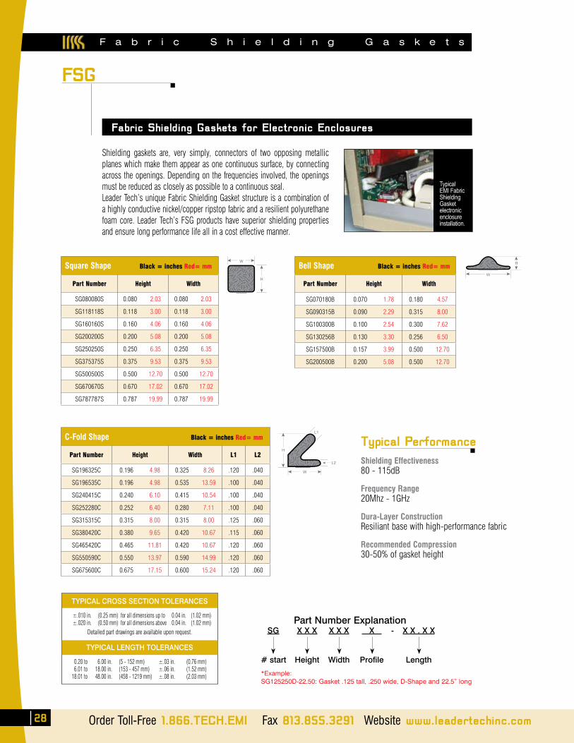
F a b r i c S h i e l d i n g G a s k e t s
28 Order Toll-Free 1.866.TECH.EMI Fax 813.855.3291 Website www.leadertechinc.com
Shielding gaskets are, very simply, connectors of two opposing metallic planes which make them appear as one continuous surface, by connecting across the openings. Depending on the frequencies involved, the openings must be reduced as closely as possible to a continuous seal.Leader Tech’s unique Fabric Shielding Gasket structure is a combination of a highly conductive nickel/copper ripstop fabric and a resilient polyurethane foam core. Leader Tech’s FSG products have superior shielding properties and ensure long performance life all in a cost effective manner.
Fabric Shielding Gaskets for Electronic Enclosures
FSG
Typical EMI Fabric Shielding Gasket electronicenclosure installation.
Square Shape Black = inches Red= mm
Part Number Height Width
SG080080S 0.080 2.03 0.080 2.03
SG118118S 0.118 3.00 0.118 3.00
SG160160S 0.160 4.06 0.160 4.06
SG200200S 0.200 5.08 0.200 5.08
SG250250S 0.250 6.35 0.250 6.35
SG375375S 0.375 9.53 0.375 9.53
SG500500S 0.500 12.70 0.500 12.70
SG670670S 0.670 17.02 0.670 17.02
SG787787S 0.787 19.99 0.787 19.99
W
H
C-Fold Shape Black = inches Red= mm
Part Number Height Width L1 L2
SG196325C 0.196 4.98 0.325 8.26 .120 .040
SG196535C 0.196 4.98 0.535 13.59 .100 .040
SG240415C 0.240 6.10 0.415 10.54 .100 .040
SG252280C 0.252 6.40 0.280 7.11 .100 .040
SG315315C 0.315 8.00 0.315 8.00 .125 .060
SG380420C 0.380 9.65 0.420 10.67 .115 .060
SG465420C 0.465 11.81 0.420 10.67 .120 .060
SG550590C 0.550 13.97 0.590 14.99 .120 .060
SG675600C 0.675 17.15 0.600 15.24 .120 .060
L1
L2
H
W
Bell Shape Black = inches Red= mm
Part Number Height Width
SG070180B 0.070 1.78 0.180 4.57
SG090315B 0.090 2.29 0.315 8.00
SG100300B 0.100 2.54 0.300 7.62
SG130256B 0.130 3.30 0.256 6.50
SG157500B 0.157 3.99 0.500 12.70
SG200500B 0.200 5.08 0.500 12.70
W
H
TYPICAL CROSS SECTION TOLERANCES
±.010 in. (0.25 mm) for all dimensions up to 0.04 in. (1.02 mm) ±.020 in. (0.50 mm) for all dimensions above 0.04 in. (1.02 mm)
Detailed part drawings are available upon request.
TYPICAL LENGTH TOLERANCES
0.20 to 6.00 in. (5 - 152 mm) ±.03 in. (0.76 mm) 6.01 to 18.00 in. (153 - 457 mm) ±.06 in. (1.52 mm) 18.01 to 48.00 in. (458 - 1219 mm) ±.08 in. (2.03 mm)
Typical Performance
Shielding Effectiveness 80 - 115dB
Frequency Range 20Mhz - 1GHz
Dura-Layer Construction Resiliant base with high-performance fabric
Recommended Compression 30-50% of gasket height
Part Number Explanation SG X X X X X X X - X X . X X
# start Height Width Profile Length
*Example:SG125250D-22.50: Gasket .125 tall, .250 wide, D-Shape and 22.5” long
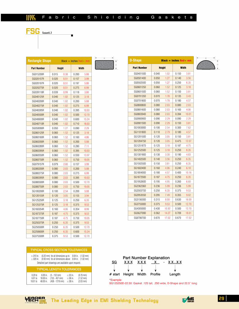
The Leading Edge in EMI Shielding Technology 29✔RoHSCOMPLIANT
F a b r i c S h i e l d i n g G a s k e t s
FSG (cont.)
W
H
Rectangle Shape Black = inches Red= mm
Part Number Height Width
SG015200R 0.015 0.38 0.200 5.08
SG020157R 0.020 0.51 0.157 3.99
SG020197R 0.020 0.51 0.197 5.00
SG020275R 0.020 0.51 0.275 6.99
SG039118R 0.039 0.99 0.118 3.00
SG040125R 0.040 1.02 0.125 3.18
SG040200R 0.040 1.02 0.200 5.08
SG040275R 0.040 1.02 0.275 6.99
SG040395R 0.040 1.02 0.395 10.03
SG040500R 0.040 1.02 0.500 12.70
SG040600R 0.040 1.02 0.600 15.24
SG040710R 0.040 1.02 0.710 18.03
SG050090R 0.050 1.27 0.090 2.29
SG060125R 0.060 1.52 0.125 3.18
SG060160R 0.060 1.52 0.160 4.06
SG060200R 0.060 1.52 0.200 5.08
SG060280R 0.060 1.52 0.280 7.11
SG060395R 0.060 1.52 0.395 10.03
SG060550R 0.060 1.52 0.550 13.97
SG060750R 0.060 1.52 0.750 19.05
SG079157R 0.079 2.00 0.157 3.99
SG080200R 0.080 2.03 0.200 5.08
SG080275R 0.080 2.03 0.275 6.99
SG080395R 0.080 2.03 0.395 10.03
SG080500R 0.080 2.03 0.500 12.70
SG080750R 0.080 2.03 0.750 19.05
SG100200R 0.100 2.54 0.200 5.08
SG120155R 0.120 3.05 0.155 3.94
SG125250R 0.125 3.18 0.250 6.35
SG125375R 0.125 3.18 0.375 9.53
SG160354R 0.160 4.06 0.354 8.99
SG187375R 0.187 4.75 0.375 9.53
SG187750R 0.187 4.75 0.750 19.05
SG250375R 0.250 6.35 0.375 9.53
SG250500R 0.250 6.35 0.500 12.70
SG250600R 0.250 6.35 0.600 15.24
SG375500R 0.375 9.53 0.500 12.70
W
H
D-Shape Black = inches Red= mm
Part Number Height Width
SG040150D 0.040 1.02 0.150 3.81
SG050140D 0.050 1.27 0.140 3.56
SG050250D 0.050 1.27 0.250 6.35
SG060125D 0.060 1.52 0.125 3.18
SG060150D 0.060 1.52 0.150 3.81
SG070135D 0.070 1.78 0.135 3.43
SG070180D 0.070 1.78 0.180 4.57
SG080080D 0.080 2.03 0.080 2.03
SG080160D 0.080 2.03 0.160 4.06
SG080394D 0.080 2.03 0.394 10.01
SG090090D 0.090 2.29 0.090 2.29
SG090150D 0.090 2.29 0.150 3.81
SG100300D 0.100 2.54 0.300 7.62
SG110180D 0.110 2.79 0.180 4.57
SG120150D 0.120 3.05 0.150 3.81
SG120475D 0.120 3.05 0.475 12.07
SG125187D 0.125 3.18 0.187 4.75
SG125250D 0.125 3.18 0.250 6.35
SG130190D 0.130 3.30 0.190 4.83
SG140250D 0.140 3.56 0.250 6.35
SG150250D 0.150 3.81 0.250 6.35
SG160240D 0.160 4.06 0.240 6.10
SG180400D 0.180 4.57 0.400 10.16
SG187250D 0.187 4.75 0.250 6.35
SG195260D 0.195 4.95 0.260 6.60
SG236236D 0.236 5.99 0.236 5.99
SG250375D 0.250 6.35 0.375 9.53
SG295355D 0.295 7.49 0.355 9.02
SG315630D 0.315 8.00 0.630 16.00
SG375500D 0.375 9.53 0.500 12.70
SG430500D 0.430 10.92 0.500 12.70
SG562709D 0.562 14.27 0.709 18.01
SG670670D 0.670 17.02 0.670 17.02
TYPICAL CROSS SECTION TOLERANCES
±.010 in. (0.25 mm) for all dimensions up to 0.04 in. (1.02 mm) ±.020 in. (0.50 mm) for all dimensions above 0.04 in. (1.02 mm)
Detailed part drawings are available upon request.
TYPICAL LENGTH TOLERANCES
0.20 to 6.00 in. (5 - 152 mm) ±.03 in. (0.76 mm) 6.01 to 18.00 in. (153 - 457 mm) ±.06 in. (1.52 mm) 18.01 to 48.00 in. (458 - 1219 mm) ±.08 in. (2.03 mm)
Part Number Explanation SG X X X X X X X - X X . X X
# start Height Width Profile Length
*Example:SG125250D-22.50: Gasket .125 tall, .250 wide, D-Shape and 22.5” long

F a b r i c S h i e l d i n g G a s k e t s
30 Order Toll-Free 1.866.TECH.EMI Fax 813.855.3291 Website www.leadertechinc.com
FSG (cont.)
Oval Shape Black = inches Red= mm
Part Number Height Width
SG140200E 0.140 3.56 0.200 5.08
SG160790E 0.160 4.06 0.790 20.07
W
HTriangle Shape Black = inches Red= mm
Part Number Height Width
SG098500TR 0.098 2.49 0.500 12.70
SG140390TR 0.140 3.56 0.390 9.91
W
H
Knife Shape Black = inches Red= mm
Part Number Height Width
SG070340K 0.070 1.78 0.340 8.64
SG106315K 0.106 2.69 0.315 8.00
SG106445K 0.106 2.69 0.445 11.30
SG160600K 0.160 4.06 0.600 15.24
SG250750K 0.250 6.35 0.750 19.05
SG312707K 0.312 7.92 0.707 17.96
SG350750K 0.350 8.89 0.750 19.05
W
H
P-Shape Black = inches Red= mm
Part Number Height Width L1 L
SG016195P 0.016 0.41 0.195 4.95 0.070 1.78 0.005 0.13
SG060275P 0.060 1.52 0.275 6.99 0.118 3.00 0.014 0.35
SG080200P 0.080 2.03 0.200 5.08 0.118 3.00 0.020 0.50
SG130520P 0.130 3.30 0.520 13.21 0.260 6.60 0.039 1.00
SG145520P 0.145 3.68 0.520 13.21 0.252 6.40 0.039 1.00
SG200395P 0.200 5.08 0.395 10.03 0.157 4.00 0.079 2.00
SG200475P 0.200 5.08 0.475 12.07 0.157 4.00 0.079 2.00
L1
L1H
W
Round Shape Black = inches Red= mm
Part Number D
SG100100Z 0.100 2.54
SG125125Z 0.125 3.18
SG160160Z 0.160 4.06
SG200200Z 0.200 5.08
D
TYPICAL CROSS SECTION TOLERANCES
±.010 in. (0.25 mm) for all dimensions up to 0.04 in. (1.02 mm) ±.020 in. (0.50 mm) for all dimensions above 0.04 in. (1.02 mm)
Detailed part drawings are available upon request.
TYPICAL LENGTH TOLERANCES
0.20 to 6.00 in. (5 - 152 mm) ±.03 in. (0.76 mm) 6.01 to 18.00 in. (153 - 457 mm) ±.06 in. (1.52 mm) 18.01 to 48.00 in. (458 - 1219 mm) ±.08 in. (2.03 mm)
Typical Performance
Shielding Effectiveness 80 - 115dB
Frequency Range 20Mhz - 1GHz
Dura-Layer Construction Resiliant base with high-performance fabric
Recommended Compression 30-50% of gasket height
Part Number Explanation SG X X X X X X X - X X . X X
# start Height Width Profile Length
*Example:SG125250D-22.50: Gasket .125 tall, .250 wide, D-Shape and 22.5” long
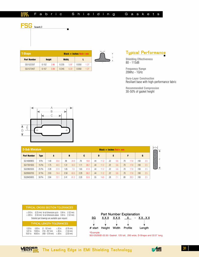
F a b r i c S h i e l d i n g G a s k e t s
The Leading Edge in EMI Shielding Technology 31✔RoHSCOMPLIANT
FSG (cont.)
D-Sub Miniature Black = inches Red= mm
Part Number Type A B C D E F G
SG140009DS 9 Pin 1.40 35.6 .98 24.9 .78 19.8 .44 11.2 .22 5.6 .70 17.8 .100 2.5
SG175015DS 15 Pin 1.75 44.5 1.31 33.3 1.11 28.2 .44 11.2 .22 5.6 .70 17.8 .100 2.5
SG228025DS 25 Pin 2.28 57.9 1.85 7.0 1.65 41.9 .44 11.2 .22 5.6 .70 17.8 .100 2.5
SG293037DS 37 Pin 2.93 74.4 2.50 63.5 2.29 58.2 .44 11.2 .22 5.6 .70 17.8 .100 2.5
SG284050DS 50 Pin 2.84 72.1 2.41 61.2 2.20 55.9 .55 14.0 .28 7.1 .80 20.3 .100 2.5
ABC
ED
G
F
T-Shape Black = inches Red= mm
Part Number Height Width) L
SG152235T 0.152 3.86 0.235 5.97 0.050 1.27
SG157245T 0.157 3.99 0.245 6.22 0.050 1.27
H
L
W
TYPICAL CROSS SECTION TOLERANCES
±.010 in. (0.25 mm) for all dimensions up to 0.04 in. (1.02 mm) ±.020 in. (0.50 mm) for all dimensions above 0.04 in. (1.02 mm)
Detailed part drawings are available upon request.
TYPICAL LENGTH TOLERANCES
0.20 to 6.00 in. (5 - 152 mm) ±.03 in. (0.76 mm) 6.01 to 18.00 in. (153 - 457 mm) ±.06 in. (1.52 mm) 18.01 to 48.00 in. (458 - 1219 mm) ±.08 in. (2.03 mm)
Typical Performance
Shielding Effectiveness 80 - 115dB
Frequency Range 20Mhz - 1GHz
Dura-Layer Construction Resiliant base with high-performance fabric
Recommended Compression 30-50% of gasket height
Part Number Explanation SG X X X X X X X - X X . X X
# start Height Width Profile Length
*Example:SG125250D-22.50: Gasket .125 tall, .250 wide, D-Shape and 22.5” long

P r o d u c t s a n d L i t e r a t u r e
32 Order Toll-Free 1.866.TECH.EMI Fax 813.855.3291 Website www.leadertechinc.com
We’ve Got You coveredReliable Board, Enclosure and Cable Shielding Solutions
leadertech shielding products
Board Level ShieldingStandard and Multi-Cavity CBS•Modified Standard Options•Custom Circuit Board Shields•
FerriShield FerritesSnap-On Bisected & Solid Bead Ferrites•Round & Flat Styles for Cables, Wires and Flex Circuits•Low, High, Microwave and Wideband Frequency-Specific •Material
Enclosure ShieldingBeCu Fingerstock Gaskets•TechSIL 5000 Conductive Elastomers•Conductive Fabric Shielding Gaskets•TechSIL 8000 Oriented Wire Gaskets•TechMESH Knitted Wire Gaskets•TechMESH Combo Strip & Gaskets•TechVent Honeycomb Shielding Panels•
CBSCircuit Board Shielding Catalog
FerriShield Ferrite Catalog
EMI problem?Our sales engineers are waiting for your call: 866-TECH-EMI (866-832-4364)
Visit our web site today to browse our complete product line, download literature and find your local sales engineer or sales representative! www.leadertechinc.com
Leader Tech is a world-leading innovator and US-based manufacturer of EMI shielding products for circuit boards, enclosures and cables. In addition to our best selling standard, modified standard and custom CBS shields, Leader Tech offers an expansive line of beryllium copper fingerstock gaskets, conductive elastomers, advanced RF absorber materials and EMI/RFI ferrites.
EMI FSG Fabric Shielding Gasket Catalog

Order Toll-Free 1.866.TECH.EMI Fax 813.855.3291 Website www.leadertechinc.com
Enclosure ShieldingBeCu Fingerstock Gaskets•TechSIL 5000 Conductive Elastomers•Conductive Fabric Shielding Gaskets•TechSIL 8000 Oriented Wire Gaskets•TechMESH Knitted Wire Gaskets•TechMESH Combo Strip & Gaskets•TechVent Honeycomb Shielding Panels•
From our Global EMI Shielding Technology Center located in Tampa, Florida, Leader Tech provides many of the world’s most respected commercial, consumer and military electronics manufacturers with precision engineered EMI shielding products and application support.
A simple call to our customer service department or your Regional Sales Engineer is all it takes to access decades of engineering and manufacturing expertise. From a simple board redesign to the development of a next-gen shielding solution, our dedicated engineering team is ready to provide you with unparalleled support and responsiveness.
Core Product Lines Circuit board shields Enclosure shielding gaskets Cable shielding FerriShield Ferrites Speciality Shielding Materials Market and Application Expertise Military Aerospace Medical Commercial Integrated Communications
Product Life-Cycle Specialists Initial design 3D modeling Prototype delivery Low-volume production High-volume manufacturing
For more detailed information and technical data on any of the product lines shown call our Sales Engineering Team or visit www.leadertechinc.com!
866-TECH-EMI
The Leading Source for EMI Shielding and Applications Support!
33

PRE05-01
12420 Race Track Rd.Tampa, Florida 33626
866.TECH.EMI(866.832.4364)
t 813.855.6921f 813.855.3291


![CUBE-BL-JP-18 CUBE-PK-JP-18 CUBE-YL-JP-18 (JP) …...CUBE-BL-JP-18 CUBE-PK-JP-18 CUBE-YL-JP-18 (JP) 1.2 Litre Capacity [JP] Operating Guide (JP)Please read this entire guide before](https://static.fdocuments.in/doc/165x107/5f0aa9a57e708231d42cb922/cube-bl-jp-18-cube-pk-jp-18-cube-yl-jp-18-jp-cube-bl-jp-18-cube-pk-jp-18-cube-yl-jp-18.jpg)