En Route Weather Data Extraction from ATC Radar Systems · DOT-FAA-RD-82-5 Project Report ATC-113...
48
DOT-FAA-RD-82-5 Project Report ATC-113 En Route Weather Data Extraction from ATC Radar Systems D. Karp 11 March 1982 Lincoln Laboratory MASSACHUSETTS INSTITUTE OF TECHNOLOGY LEXINGTON, MASSACHUSETTS Prepared for the Federal Aviation Administration, Washington, D.C. 20591 This document is available to the public through the National Technical Information Service, Springfield, VA 22161
Transcript of En Route Weather Data Extraction from ATC Radar Systems · DOT-FAA-RD-82-5 Project Report ATC-113...

DOT-FAA-RD-82-5
Project ReportATC-113
En Route Weather Data Extraction from
ATC Radar Systems
D. Karp
11 March 1982
Lincoln Laboratory MASSACHUSETTS INSTITUTE OF TECHNOLOGY
LEXINGTON, MASSACHUSETTS
Prepared for the Federal Aviation Administration, Washington, D.C. 20591
This document is available to the public through
the National Technical Information Service, Springfield, VA 22161

This document is disseminated under the sponsorship of the Department of Transportation in the interest of information exchange. The United States Government assumes no liability for its contents or use thereof.


ABSTWCT
his report describes the results of phase I of the En Mute Wdar
Weather Program. me objective of this effort was to develop techniques forgenerating accurate en route weather reflectivity estimtes in the presence ofground clutter. A candidate weather data extraction processor is proposed foruae with either the ASR+TD or ARSRWD radar system. Principal features ofthe candidate processor include:
(1) an antenna port (to pemit use of an appropriate polarization),front end (with R-2 STC) and quadrature video s~pling subsystemwhich are separate from that used for aircraft surveillance
(2) use of a ground clutter map to select the form of clutter rejectionto be used in each individual range-azimth cell to estimte variousweather reflectivity levels, and
(3) spatial/teWoral smoothing of the cell reflectivity estimates
The key elements of the s~geeted signal processing techniques were evalllatedusing data from MTD tests in Bedford, VA, Burlington, VT, and Atlantic City,N.J.; however, the full system has not as yet received design validation/re-finement and operational evaluation by ATC controllers. In particular,methods for identifying second trip weather ethos should be addressed in thefull system validation program.
iii

IN MEMORY
David hrp, leader of the En Route WeatherExtraction Project at Lincoln Laboratory,and author of this report,was the victim ofan auto accident on August 15, 1981.
v

John R. Anderson contributed significantly to the analysis and proposedsignal processor configuration as well as providing the filter responseplots. &rbara Formn developed the clutter mp analysie software. ~chnicaldirection, encourageunt and discussions by tinneth @onley played an iwor-tant role in the final prod{lct.
I
vi

CONTENTS
I INTRODUCTION
11 PROGRAM TO DATE
111 CANDIDATE RADAR FRONT-END AND SIGNAL PROCESSORFOR WEATHER DATA EXTRACTION
A. Front-EndB. Digital Signal Processor
IV CONCLUSIONS
REFERENCES
APPENDIX A WEATHER RADAR PEBFOHCE1. Candidate tidars2. PrecipitationReturn Comarisions3. Clutter/Weather4. ARSR Operation5. Multiple Trip Weather Ethos
APPENDIX B CANDIDATE CLUTTER FILTERS
APPENDIX C LIST OF ACRONWS AND ABBREVIATIONS
1
2
447
1s
20
A-1A-1A-1A-6A-nA-12
B-1
c-l
vii

ILLUSTRATIONS
11-1
111-1III-2111-3
111-4111-5111-6III-7111-8111-9
111-10111-11
A-1
A-2A-3
A-4
A-5A-6
B-1
B-2
B-3B-4B-5
BVA Zer@Velocity Filter ~tput Withhtenna Stationary
ARSR-MTD With Weather Channel fiocessorNormalized Weather/Clutter LevelsFrequency Rssponse of Candidate FIR ClutterFilter
57 dBz Cells Raquiring Filter //150 dBz Ulls Rsquiring Filter //250 dBz Cells Requiring Filter Ill46 dBz &lls Rsquiring Hlter /}346 dBz Cells Mquiring Filter /)141 dBz Cells Wquiring Hther Nlter //2orFilter ~13Mnstly //2
41 dBz Cslls Wquirlng Filter /)330 dBz Cells Wquiring Filter //3
ARSR-4 Front-end Performance Parameters(Asswed)
Stem Elevation Profile DataSignal-to-Noisevs ~nge for Weather andGround Clutter
Clutter/Weather %tioa for Specific Parametricbnditions
Bedford 30 dB Clutter 10 nmi Wnge WngsGtegories of fidar M Echo Intensity(As klated to NWS bvels)
4-Pulse ~uiripple Finite Impulse &sponseFilter
4-Pulse ~uiripple Finite Impulse RasponaeFilter
Standard 2-Pulse WncellerStandard 3-Pulse CancellerASR-MTD Wgh-Fass Fi1ter ksponse
viii
356
89
10111213
141516
A-3A-5
A-7
A-8A-9
A-10
B-2
B-3*4B-5&6
-- ..... ...J

I. INTRODIJCTKON
The purpose of Ph@se-I of the En Mute ~dar Weather Extraction Programwaa to develop and recomend techniques needed to generate accurate weatherlevel signala in the en route environment. Mphasis waa to be placed on theaccurate measurement of precipitation reflectivity in the presence of groundclutter. The results of previous work in this area by the FAA, NationalSavere Storms Laboratory (NSSL), FAA ~chnical Qnter (FAATc), and the JohnsWpkins Applied Physics Laboratory were to be used aa technical background forthe study. me techniques used by the FAA in Sef. 1 and by the NationalWeather %rvice in Wf. 2 to provide six levels of weather informtlon wereinvestigated as a baseline for the feasibility and utility of this approach.
It should be emphasized that the principal objective of the tise Ist~ies was to examine a variety of candidate techniques using, when possible,actual Wving Target Datector (MTD) data to aasess the performance limitationdue to ground clutter. me reeulting candidate weather radar front end andsignal proceeaor has been baaed on this practical experience, but hae not asyet been fully implemented and evaluated in an operational environment.
Currently, weather information la obtained from the en route radars andsent to the Air hute Traffic @ntrol &nter (ARTCC) via the wather and fixedmap unit (WFN) and common digitizer (CD). me WF~ thresholds the radarvideo and the CD ganeratee digital meaeages giving the azimth and range ofweather threshold croaeinge and tranemite this information to the ARTCC whereit is used to produce a digital display of the waather. me measurement ofthis weather data suffers from inaccuracies due to circular polarization (CP)attenuation, sensitivity time control (STC) attenuation, and the velocityresponse of the moving target indicator (MTI) circuitry used to eliminateground clutter.
Wdern radar digital signal proceeaora have been developed which tend toeliminate the effects of ground clutter, angel false slam, and precipitationechoes in order to furnish displayable target reports of moving aircraftonly. ~eae proceaaors are suitable for use with the FAA L-Band radars usedto perform surveillance functions in en route air space. To eliminate falsealarms due to precipitationechoes, adaptive, linear constant false alarm rate(CFAR) techniques have been used in the Mncoln MTD radar signal proceesora.Under this program it was planned to uee raal-time MTU measurement in range-anglewelocity-apace after normalization, to estimte the reflectivity factor(i.e., z~alue) of precipitation returns.
The technique developed for uee with the en route radar equipped with MTDproceasin
fuaee a two-level ground clutter map to aid the mather extraction
pr0ceas[3 . Baeically the eignal processor generatee tw sets of weatherthreshold crossings. tie uses the total received ener~ of the radar returns
... . ., .—....’--... -.--m_ .=-.....

and the other uses only a linear combination of the no~zero doppler filteroutputs. For high clutter cells, the non-zero frequency filter outputs areused. Othemise the total received energ is used. ~ese data are then inte-grated over three scans and spatially smoothed to generate a contoured weathermap. ~is process is utilized for tw selectable zvalue levels of precipita-tion reflectivity.
II. PROGRAM TO DATE
A program to enhance the clutter perforunce of tertinal (ASR) anden route (ARSR) radar system by introducing MTD processing has been underwayfor some time (@f. 3). & a by-product these MTD processors were adapted toproduce two calibrated, contoured levels of rain reflectivity within coverageof the sensor. It was believed that a six-level weather extraction processormight reside in the back-up channel MTD processor, and uae the fine-grain,temporally smoothed ground clutter mp (~intained by the MTD for zeroweloc-ity target threaholdingagainst clutter) to subtract from the current meaaur,~ment of weather plus ground clutter, producing a cell-by~ell eetimte ofweather only, Sarly efforts focuesed on exploring this possibility by devel-oping emoothed ground-clutter maps ueing the ASR-7/MTD at bxington, MN, theASR-7/M~ at Burlington, VT (BTv); the FPS-67/MTD at Bedford, VA (BVA); andthe inetrmented ASR-8 at the FAATC, Atlantic ~ty, N.J. 2his etudy was con-ducted during the period January-September, 1979. ~wever, by the fall ofthat year we were convinced that this technique cotid not be mde to supportweather extraction satisfactorily for the following reasons:
1) me eetimate of ground clutter exhibited higher than expected variancebecauaa the “large” croee section cells consisted of only a few eingularitias,and the single-frequency radar measurement coupled with this feature producedlow frequency variatfone which were tracked by the single-pole low-paas filterused for smoothing. me variations in mean radar croae eection were aa greatas +6 dB, and it was determined that rejecting the ground clutter return atzer~-velocity wuld be required in order to develou an estimate of thenon-zero velocity component of the weather in the cell(a) of intereet. hexample of ground clutter amplitude variation with the BVA FP%67 antennastopped ia ehon in Fig. II-1.
2) Those celle that did not exhibit the above variations (moded areas)did exhibit very slow variation of up to 6 dB from day to day, aeedngly as afunction of wet/dry conditions. me MTD processed approximately 5x10⁵range/azimuth clutter map cells (1/16 nti x O.7°), and although only 10%(above +30 dB ~/~) were affected by the above problem, thie waa con-sidered to be sufficiently severe (statistically) to prevent recommending thatthie technique be implemented.
2
-,, ... .... -----

Az = 300°
EL TILT * 1.5° (NOMINAL-l”)
SAME CELL
6 dB ATTENUATION IN IF
PEAK GilNo>+51 dB
I I 1 1 81
SCANS (12 SECSISCAN)
Fig. II–1. BVA zero-velocity filter output with antenna stationary.

3) Use of the ARSR/M~ processor for surveillance and multi-level weatherextraction processing complicates the antenna polarization, range, and radar-STC nomlization of the weather thresholds. H the system were to be har&wired, and pre-computed normalized weather thresholds implemented in orderedrange, then radar/weather processing could c~exist. Mwever, the radar MTDsubsystem was to be implemented using fault-tolerant architecture whichallowed for restructuring of the processor to non-range order under softuarecontrol. ~us to msintain this fault-tolerant architecture would reauire on-the-fly re-coqutation of weather thresholds module-by~odule.
4) Finally, use of che Depplerfilter bank optitized.for aircraft’detec-tion for weatherextraction processing was deemed inappropriate.. ~is is truebecause.alarge.fraction of the precipitation cells will have a velocity 8pe~trum centered at zero radi”a~velocity..... Hsnce it would be necessary..toex-clude a. large velocity.interval around .zer~velocity to tinimize false aim .craft target decla,rations. ~is low.. frequency filtering.would .SUP.PC?S.Sweather returns (along with the ground-clu:tcerreturns) and result in dtstor.ted weather contours.
The above considerations led us to investigate the.possibility of imple-meeting..a.separate weather channel processing system which could operate inparallel with.;and independently of the MTD system. ~ia, o.fcourse, gives upaccesa.to the MTD zero-velocity.clutter map, but this was no longer considered...to be useful fc,rextracting weather attribute from weatherplus~round-c ltit-terradar :cella.
111. CANDIDATE RADAR FRONPEWD AND SIGN& PROCESSOR FOR WEATHER DATAE~WCTION
me reminder of this working paper deals with a candidate weather ex-traction processor for use with either the AS&MTD or ARSkM~ radar syate~being developed for FAA-ATC aircraft surveillance. ~eo, Incltied in theAppendices are a comparison of the weather return/receiver nofae ratios forthree candidate radars, data to place clutter and precipitation levels inperspective, cements on the operation of the ARSR/MTD in the field, and dataon candidate clutter filters.
A. Front-End
A nmber of front-end confi~rations were considered, during the courseof this study, and all could be mde to support weather extraction. Thecandidate front-end configuration shown in Fig. III-1 is the preferredarrangement, as it decouples the weather channel from gain variation inducedby changes in radar-STC curves. It does, of course, introduce a 1 dS leas inthe primsry channel, but this ie considered acceptable aa tilting the antenna
4
.— -----

wDUP
6.dB COUPLER tNTROOUCES’0.5-TO.1.0 dB LOSSIN MTD CHANNEL
ST;LO6 LEVELS
N.1T04I.F. 1
PROC. N PUKE
OUAD a FIR
vIDEO FILTER
1 F =
. . . . . . . . .
COHOREF PROCESSING —
. . . . . .*
. . .
- N PuLSEFIR
6 8WS/—
- FILTER
t ‘t8 SAiPLES/ 9.N SA’MPLES/ 1 SAiPLE/
CPI CPI CPI
Fig. III-1. Functional block diagr= ARSR-~ with weather channel processor.
m
40 -
\57 dez
\\
30 -
50 dBz
46 dBzm., 20 -z 41 dBz
;wmA
: 10-w$ 30 dBz
G
o -
-lo
t-201 ,
1 10 100 (NAUTICAL MiLEs)
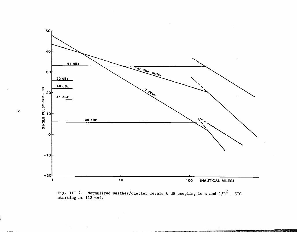
Fig. III-2.starting at
Nomalized112 mi.
weather/clutter levels 6 dB coupling loss and l/R2 - STC

I
down will more than compensate for this loss in the MTD channel. ~anelationto IF, quadrature video processing, and A/D converter sampling of I and Q var-iables is the same as specified for the ARSR-MTD. 2he weather channel STCshould be operated at a l/R2 rate, to normalize all weather aigr~alsaa shownin Fig. III-2.
Wring the investigation of candidate filters, the clutter map, aa re-corded at BVA, was run against four filters, and a cooaervative clutter rejec-tion requirement used to exatine the resulting weather mapa. me plots ofFigs. 111-4 to -11 show the location of cells requiring the use of a givenlevel of filtering to achieve detection of weather signala of a specifiad in-tensity. me maps were prepared using alternate CPk, yielding 256 azimuths,and the limiting range of clutter at BVA of approximately 80 nmi. mere were40960 range-azimuth cells (1.4” x 1/2 nti x 80 nti) prOcesaed in cOvering theweather (636 one-eighth nmi gates were processed in One nmi blOcka)~ and achoice of four clutter filters was available for each cell. me clutter can-cellation of the filter(a) used in each mapping exercise is given in TableIII-1; the response of each filter is as described in Appendix B.
B. Mgital Signal Processor
The high-speed digital eignal proceaeor (ground clutter filters) performsa..functlon.eimilar to the MTD Doppler filter bank, but is tailored to theweather/ground clutter...problem.and operatea slightly different~j. A majorelement of this:study waa to characterize the ground clutter statistics asthey applied”to theweather extraction problem, and te develop a set ofreasonable “filterswhich wodd pertit accurate estimationof weather in thepresence of ground clutte”r. me obvious choice waa.an..all-pass filter whichwndd be:optimum for large &/Ci range-aziath cells, since this filte:r.:intro-ducea zero-error into the weather.eatitita, and one of the tm MTD.filters”forweatherwas all-pasa. Moat cells, for most weather levels, till be processedusing this filter. ..Foasibly10% of the cells/levels will require high-passfilters to improve..the ~/.~ ratio prior to estimatingthe.. precipitationreflectivity.... Another simple filEe=r,which tight be the next.cbOice, iE afour pulse Finite Impulse Wsponse (FIR) ffltei. ~is filter mdd operate onthe 8 pulses in.a CPI (I and Qaamples for eachpdse) to yield 4 valvea ofsteady state output. me weatberlavel wndd””be.estimated from .thaae 4values. me transfer function of this filter is shown in Fig. .111-3. 2heclutter rejection for this filter is approximately -12 @, which wndd handlethe clutter at rangea greater than 20 km for moat weather levels of interest.2his filter will reject some of weather spectra which fall in the range from-2 m/s to +2 m/a and hence should OUIY be used when necesaarY. ‘e ‘mall per-centage of range-azimuthcells which require more than 12 dB of clutter rejec-tion could use 2-pulse or 3-pdse cancellera such as are described in AppendixB.
7

0
-lo
-20
-30
-40
-o~o 50 100 150 200 250 300 350
4 PULSEt2 dB RIPPLE
10 dSCLUTTERREJECTION
h(n) =-3, 1, 1, 1
FREOUENCY (Hz)
Fig. 111-3. Frequency response of candidate FIR clutter filter.

....’. ..“.,..
,.....
... \\,., ...
?.. , .........,.
I I I I
20 NMI RANGE RNGS
Fig. III-4. 57 dBz cells requiring filter //1.
9

..”’,...
.,.”.,..
...,.....
.,.,.,.
20 NMI RANGE RNGS
Fig. III-5. 50 dBz cells requiring filter //2.
10
——..—-

20 NMI RANGE RINGS
Fig. 111-6. 50 dBz cells requiring filter //1.

,..”.,:
,..’,,.
....!. ‘\...
....,..
20’ NMI RANGE RNGS
Fig. III-7. 46 dBz cells requiring filter /)3.
12

20 NMI RANGE RWGS
Fig, 111-8, 46 dBz cells requiring filter //1,
13

......’”.<+
,,..’..,..
,,.
;..
,.
, ‘,.,.,,...
20 NMI RANGE RINGS
Fig. III-9. 41 dBz cells requiring either filter //2or filter //3,mostly //2.
14

.:....’
..... ,.....,.
..,...,.,...
1 I I I
20 NMI RANGE RNGS
Fig. 111-10. 41 dBz cells requiring filter /}3.
15

....
...
. ..,.,
...
20 NMI RANGE RWGS
Fig. 111-11. 30 dBz cells requiring filter //3.
16

I
TASLE III-1
l~ATHER MAPPING EXERCISE SWRY
Precipitation Levelmz Descriptor—
57 Intense
50 Very Strong50 Very Strong
46 Strong46 Strong
41 ~derate41 Wderate
30 Weak
me analyais was carriedand 30 *Z corresponding to aIII-1 smrizaa the orsDDinE
&lla ~quiring FiltarType (Cancellation)
FigureIII-
1 (12 a) 4
2 (20 dE) 51 (12 a) 6
3 (40 dE) 71 (12 ds) 8
2 or 3 (20 or 40 dS) 93 (40 ds) 10
3 (40 m) 11
out using rain intensity values of 57, 50, 41,range from intense to weak uraciDitation (Table
..- exer-cisewhera the WS lev~le o; precipitationare aa defined in Fig. A-6). For the intense precipitation,most of the cellscan be processed by the all-pass or Type O filter; Fig. 11I-4 shins the fewcells requiring Filter Type 1, a four pu2sa cancellar. With leaa conservativecriteria even fewer cells would require this filter. 2he 57 dRz intensitysignals did not require the use of the 20 or 30 dS filters.
As the rain signal decreaaee in intensity, mora clutter filtering isrequired aa illustrated in Fig. III-5 and -6 which show the cells requiringthe use of the 20 and 12 dS filters respectively. mere were few cells whichrequired the 20 @ filter. Further decreasing the intensity to 46 dRzrequires more robust filtering as ehon in Fig. 111-7 and -8, where both the46 ~ filter is engaged for a few cells, and a large nmber of cells requiretha 12 dS filter. The 20 dS filter is required for processing the 41 ~zintensity level as ie the 40 & filter. See Fig. 111-9 and -10. Again thenmber of cells requiring the large clutter attenuation is small. Finally, atthe weakest intensity level, 30 dRz, the 40 dS filter is required to rejectclutter in a large nmber of cells.
It is believed that a alight change in the clutter rejection criteriacould reduce the need for the high-attenuationvalue filters. Parametricanalysea were not carried out for a nmber of other clutter rejection options.
Each filter operates on all data through weather level thresholding, atwhich point the site-dependent up selects one of four threshold declarationsfor each 1/2 nti range interval. In the absence of rain, weather thresholds
17

—
are not declared, even though random threshold crossings occur. me Wp iscreated in clear weather, and iterated to reduce false declarations to “nearzero”.
Scan-to-scan smoothing, and contour start/stop detection ie as epecifiedfor the ASR-9/M~ two-level weather extraction processor. No~nally, all fivecontour Mps could be continually mintained and updated, but it ia likelythat only two would be displayed sfmultaneouely, and it would, of course, bemore cost effective to develop only the contoure which are to ba dlsplayad.still, this represents straightforward bit=p processing and relativelysmall, reliable special purpose microprocessors can be used, to support thesefunctions.
IV. CONCLUSIONS
me ASR/M~ and ARSR/M~ radar system can be used for weather dataextraction, evan though their bea patterne and scan rates are tailored f~aircraft surveillance rather than radar meteorology. Based on our sttiiesueing clutter from BVA (chapter III) and the M~II experience at FAATC andBurlington, VT[3], We have concluded that ground clutter can be automat-
ically suppressed without “seriously” cOwrO~aing the weather extractionfunction, using low-order digital filtering. Spatial/temporal smoothing andcontouring algoritti developed for the MTD two-level weather extraction pr~ceseor will support the six-level processor (five-thresholds). We see noadvantage (and, several disadvantage) in cOmbining Mm and weather extractionproceaeing in a single unit, and recomend that they be implemented separ-ately.
me key concepts involved in the candidate weather processing eyetem are:
(1) use of a static ground clutter map to select the form of clutterrejection to be used in a given range-azimth cell
(2) iteration of the ground clutter mape in a variety of clear weathersituations to reduce false declarations
(3) aaseesment of clutter rejection technique baaed on actual clutterdata
(4) spatial/temporalsmoothing and contouring
(5) l/R2 STC and AID converter of I, Q sapling, and
(6) an appropriate polarization for the weather channel.
These have individually been demonstrated over the past few years[3-5].However, it mat be reemphasized that the fdl system design validation/refinement and ATC controller evaluation has not yet been carried out.
18
-— ————... -!,. -.-—

It should also be noted that there are substantial inaccuracies* (e.g.,due to weather return statistics, breakdom of the beawfilling assu~tionand/or bright band occurrence) in the weather return estimates which one canobtain with an ASR or ARSR even when clutter is not present. In particular,the operational evaluation should consider:
(1) methods of identifying and flagging situations in which second tripweather ethos are contained in the estimated first trip weatherdata, and
(2) the degree to which the uae of a larger nmber of weather thresholdlevels for the ASR or ARSR my imply a greater accuracy in the esti-mates than is in fact the case.
*Appendix A discusses a nmber of these inaccuracies,

KBFEEENCES
(1) K. Coonley, D. Hopson, “Use of Air Traffic Control hdars for HazardousWeather Data”, FAA kport 9550-1 IIWT-1OO-33.
(2) E. B. Dobaon, F. L. tibison, A. hnold, T. G. Knnrad, “Detection ofSevere Weather by FAA ~dars”, Baport No. FW-RE79-91, Final ReportThe Johns Hopkins University Applied Physics Laboratory, September, 1979,
(3) D. brp, J. R. hderson, “~ving Target Datector (~d II) SmwryKsport’”,ATC-95, Lincoln bborato~, MIT, Project Report, November, 1981.
(4) R. J. Mviak, D, S. Zrinc, D. S. Si-ne, ‘“~ppler Weather Wdar”,Proceedings of the IEEE, Vol. 67, No. 11, November 1979.
(5) J. &derson, “EvaluatingGround Clutter Hlters for Weather Molars”, Pre-prints, 20th tinf. on &dar Meteor., b. Meteor. Sot., Boston, Mssd.,314-318, 1981.
(6) B. G. Laird, “h hbi~ity Maolution by Mndom Phase Processing”, 20thConf. on Radar Meteor., Boston, Masc., her. Meteor. Sot., 327-331, Nov.1981.
(7) W. D. Zittel, “Echo Interpretation of &vere Storms on tirport Surveil-lance kdars”, Kaport No. FAA-R&78-60, NatiOnal Severe Stem hbOra-tory, Norman, OK, April 1978.
(8) K. E. Wilk and J. T. holey, “FAA Radars and ~eir Msplay of ~vereWeather (~understo~)”, FM-RB 80-65, NstiOnal Severe StormLaboratory, Normn, OK, July 1980.
20
—. ,..—.—..,.—.,.—.—...——.--. —-—-—. --..-,.., . . . .... .. . . . —.- —...-..A

APPENDIX A
WEATWR WAR PERFOHCE
1. CANDIDATE WARS
me pertinent performance parameters for three radars of interest arelisted in Table A-1. NEXRAD is a hypothetical next generation coherent radaroperating at S-Band. It my be thought of as a poaaible contender for jointuae by the FAA, the Mr Force Weather Service and the National Weather Serviceas the next generation en route weather radar. The ARSR-4~TD (ace Fig. A-1)should be viewed as the present ARSR-3 modified by the type of front-endalterations described in this report and by the addition of MTbtype process-ing. Since design e~erience and field data haa been obtained on a radarsimilar to the ASR-9/MTD, performance parameter have been incltied for it aswell.
2. PWCIPITATION W~RN COWWSIONS
In the use of radar for precipitation measurement the principal prope~ties have been the total returned power or the temporal variation of thatpower from storm ragions. It ia generally accepted that severe atorma of thetype that present significant hazards to aviation, contain greater quantitiesof larger water droplets and thus produce larger radar returns. me receivedpower Pr from a vol~e of precipitation is:
Pt GT GR A2
‘r = at
(4T)3 R4
Ut is calculated as follows, aaaming the beam to be filled with hydrmscatters (“hydrometers” ):
(Reflectivescattering vol~e) x (Scattering coefficient, n)
for Gauaaian Beam , two-way, and
n=5.6 x 10⁻¹⁴ rl.6
~4
where:
r = rain rate in mmlhr.
A-1

TABLEA-1
COWARISON OF &/k ~R WDIDATE RADARS
Ii
Faramet er NB~D mSR-4/MTD ASR-9/MTD
6 6Pt
61 x 10 watts 2 x 10 watts 1 x 10 watts
G +43 @ +33. 5 dB +33.5 dB
e 1“ azimth 1.5° azimth 1.3”azi~th(oneway 3 dB width)
$ 10 elevation 5.0” elevation 4. 8“ elevation(on&way 3 dB width)
(withCSC2 mods)
T 1 ~sec 2 ~sec 1 ~sec
L 1 dB 3dB 2.5dB
Lt Ids Zds 2.0ds
LP
Idn Ids 1.0ds
NF 1.5 dB 3ds 3.0ds
BWe 1 M& 500w lW
R 10 b ; 2 - 3WBZ lob>z.3odsz lob; Z = 30dBz
P= -63 dnm -77dBm -76.5dBm
No
(- K T BW,NF)-112.5dEm
I-114ABM I -111.0dsm
I , I
tilb +50 As +37dB +34 a

~ “’”
Tx ,
r“0.7. dB
t
DUP
l“..; ~
VJQ 0.6 dB
1.0 dB.
JOINT ~BPF , STC K
0.6 d~
P,
0.7 dB ~
NF =3dB
BW = 600 KHzLOSSES
LR = 3 dB RECEIVE LINE LOSSES
LT s 2 dB TRANSMIT LINE LOSSES
Lp = 1 dB PROPAGATION LOSS
Fig. A-1. ARSR-4 front-end performance parameters (assumed),

When applying this equationdeserve consideration. me first
to the en routeis the statistical
power from precipitation. A single measurement is
radar, several factorsnature of the receivedlikely to contain large
errors. A second factor is the beam-filling assumption used in the derivationOf this equation. While this is a good approximation for radara with a narrowpencil beam, such aa those used by weather radara, for a fan beam radar it~Y underestimate the severity of the storm because of non-uniform heightprofiles or low altittie storms my only partially fill the antenna beam.
~ia problem was pointed out in kf. 1 by @onlay and ~paon. An axamplaof stem profile data is shon in Hg. A-2. ~ese data indicate that theaverage power from integrating over the coverage height till, In general,indicate a lower z value than the maximum actual z value in that cell. Forexample, in Figure 3 of the reference, at 85 ti, where a 40 ~z region occurr-ed between 4 to 6 b altitude, the volwe-average is below 30 dBz.
Another factor ia that non-weather related targets within the beam cover-age Introduce errors in the neaaurement accuracy. For the en route radar theneed to provide lW altittie aircraft coverage, necessarily introducessubstantial ground clutter return energy in the received signal.
me processor till use a pulses per range gate to estimate Pr, and there-fore z-level. The ARSR will operate at approximately 400 Rz, thus the CPIinterval till be 20 met. me weather signal ia substantially correlatedpulee-to-pulse (2.5 wee), but does de-correlate to some extent over the CPI-intarval. 2he extent of de~orrelation is related to the velocity tidth ofthe return, and for purposes of generating athe spectral width is assmed to be ~ussianeffective doppler width of 43.5 &. mesamples is given by
Neff = 2WT
where W = 43.5 % andT - 20 mec
Thus there are approximately two independent
typical valua for de-correlation,with 2 mec variance, yielding annmber of effective independent
Swlea per gate per CpI. ~ghtrange gates till be amed, and it is assued that these samples are essen-tially uncorrelated, yielding the equivalent of 16 independent saples forestimating the z-level. Ualng either voltage or power smmtion (approxi-mately) the one-standard deviation of the estimate will be about 1 dB. meestimate variance till be somewhat greater for narrower width weather returns,and somwhat smaller for wider width weather returns. Scawto-scan andspatial smoothing improve the eatimtor to some extent, and our experiencewith the ASR-MTU tin-level processor indicatee that this form of z-levelintensity estimation will be adequate.
A-4

18
16
14
12
10
8
e
4
2
080 100 120 140 160 180
181 (
14
12 (C) 1800 GMT
RANGE (KM)
Fig. A-2. StOm elevation profile data.
I

3. CLUTTEMWEATHER
Figures A-3 and A-4 provide some perspective on the dynamic range of thesignala involved and the relationship between ground clutter and weather re-turns for the candidate ARSR and N~Ao systems likely to be operated at hband and S-band by the FAA in the future. Fi~re A-3 shows parametric curvesof S/N for weather and ground clutter returns for the ARSR-4/MTO operating atL-Band and the NEW, a next generation coherent weather radar, operating atS-Band. ~g. A-4 shows the Clutter/Weather ratioa for these aystema for spe-cific but important parametric conditions. me weather level chosen is theuPPer bOund of the NWS weather level 1 region, and would be the lowest levelprocessed for extraction by the ARSR system. me ground clutter back scattercoefficient of ’40 dBo is typical of much terrain that would be visible toen rOute weather radara: fie important featurea of these curvee are:
a. Very wide dynamic range, especially when -10 dBO clutter isconsidered, and weather levels greater than +70 dsz.
b. With the beams pointed at their lowest useful elevation angles(for long range coverage) Ci/W ratioa are high, and someClUtter titivation is required, in order to extract weatherinformation without attendant ground clutter falae alarms.
c. me ARSR problem is more difficult at this elevation angle,and it stays that way, whereas the N~~ system does tilt upand gets eubatantial relief in-close from typical ground clut-ter. At 1.5° elevation (for N~Ao) with a -25 dB first aide-lobe (one-way) the close-in ground clutter problem for +3o dBzweather is non-axiatent. me ARSR operatea at this elevationfor enhanced long-range A/C coverage and moat cope with theground clutter on each scan.
Another feature shown in fig. A-3 is the ARSR ti/No after typical radarI/R4-STC front-end attenuation (typical of BVA-MTO operation), In the range20-100 b the Ci/No is approximately +30 dB. Fig, A-5 shows a +30 @ ~/NCmsp of BVA, obtained using a dump of the temporally smoothed ground clutter
~P . ~/No exceeds +30 dB within the closed contours, and therefore repre-sents regions exhibiting higher than -40 dBO ground clutter reflectivity.mese regions therefore, in the abeence of weather, exceed the 30 @z weatherlevel threshold by at leaat 18-25 dB (it wodd by 10-17 dB for NE~D), andzero-velocity clutter suppression is required to avoid false weather display.For this particular site much of the hilly terrain subtends negative elevationangles to the radar, and NSRR~ wuld have a smaller percentage of the areaexceeding this threshold level. kyond 50 nmi at BVA, very few range-azimthcells will require clutter dtigation, even at the lweat weather threshold(30 dBz). A chart of the NWS weather levels ia shown in Fig. A-6. For thehighest weather threshold (57 dBz), only a few sin~larities would requireclutter filtering or possibly fixedwap censoring.
A-6
.. . . . .. . . ..—-..

140
[
NEXRAD -S-BAND (2?00 -2900 MHz)
ARSR - L-BAND (1250- 1350 MHz)
\\
120 - \\\
\\\\
\\
100 -\ \
\ \\ \
\ \
D
80 -~
~
2
60 -:gw \\
\\
40 -
20 -
RANGE - km
o0.1 1 10 100
I Fig. A-3. Signal-to-noisevs range for weather and ground clutter.

50
40
30
20
10
0
-lo
RANGE - km
0.1 1 10 100
Fig. A-4. Clutter/weather ratios for specific parametric conditions.
A-8

Fig. A-5. Bedford 30 dB clutter 10 nmi range rings.
A-9
.— .. . . ... .

57
50
46
41
30
0
NEW CODE
9.E~EL
EXTREME
INTENSIVE
MODERATE
--- -
7Y-FVFL ViR; - -
STRONQ,.,....,,.,.,,,,, -—- —LEVEL
~ ; STRONQ
“w_—-—i.
uEVEL WEAK1.
EXPECTED CONDITIONS
POSSIBLE WINDJURBU LENCE GUSTS w LIQHTNINQ
severe extenoive large yee
---- ---- --- --- --
severe organized Ikely yea
--- —-- --— --— -— --
severe poealble -- yes
--- ——— --— --- —-— —
severe -- -- yes
—-- —-— -- -—- --- --
moderatel - - ‘- ‘-eevere
--- --— -—- —-— —-- —
moderatel - - -- --
Fig. A-6. categories of radar Wx echo intensity (as related to WS levels).

bother feature which should be apparent from the BVA clutter map is thatmost of the features are small in area compared to typical weather sytems, andeven though clutter filtering will suppress and distort some weather signals(near zero-velocity), spatial continuity considerationsshould allow for rela-tively accurate contouring and smoothing, even for the lowest thresholdedlevel.
Present NWS weather radar systems depend on intervention by trainedweather radar meteorologists to identify these features ae ground clutterrather than rain, but the ARSR-MTD system will require automated suppreeslon.The NHRAO system will also suppress ground clutter automatically.
4. ARSR OPEWTION
The ARSN( )/MTD, is ueed for long range (200 nti) air rOUte surveillanceand uses a sector beam antenna (1.5“ azimuth by 5“ elevation with Csc2
modification) rotating at 30”/aec. (12 seconds per scan). me narrow azimthbeam and high scan rate broaden the ground clutter spectrum, and this compli-cates the problem of clutter mitigation, since weather spectrm which overlapsmust be euppresaed as well. me large beam (compared to the NEW 1° pencilbea) will generally not be uniformly filled with hydromateora (especially atlong range) and the estimate of rainfall rate will be low aa a consequence.However, for purposes of this treatment, be~filling la asamed at allrangea.
me radar will be operated in a dual-staggered PRF mode to support ~Dprocessing, with each coherent proceaaing interval (CPI) consisting of atleast 8 pulses. Weather will be proceeeed on alternate ~Ie. bnsiderationsof weather level estimate variance will be based on 8 pulee CPIS, as presentlytested with ~ weather extraction processors. me @Is till be synchronizedin azimuth to support Mm clutter map maintenance, and will permit scan-to-scan smoothing in range-azimth space. me weather processor will be synchro-nized with the MTD and probably uae the sme range gate timing of 1/8 nmi(1.54 p aec) sampling. Thus, although the separate weather extraction pro-ceaaor ia independent of the Mm, there are timing constraint impoeed by MTDaignalling/processingetrategy. The 1.5° elevation angle of the ARSR antenna,used in this discuaaion, is lower than present syatema (normally 2.5“ or high-er), but wodd probably be used with ~ proceaaing, since clutter mitigationcan be managed, and this gains about 4 0 in sensitivity for long range andlow altitude aircraft. It does, of course, i~ose an additional burden on theweather extraction processor.
A-n

—
5. ~LTIPLE TRIP ~ATHER E~OS
One additional problem common to radar measurement methods using rela-tively high and constant PRF’s is that of second-time-around (STA) echoes,
ariaing from longer range targets whose round trip echo the exceeds the iwterpulse period. For a 1200 PRF characteristic of an ASR, this un~biguo”arange limit is approximately 68 nti. Thus, possible weather returns fromdistant storms in the 90 to 110-nmi range interval, for example, will besuperimposed onto desired returns between 20- and 40~mi range. The resultantreflectivity display can lead to highly erroneous conclusions regarding theactual weather situation. Exmples of this on an ASR in Oklahoma are shown inZittel [7].
Several methods have been suggested for titivating this problem:
(1) comparison of the weather display at different PRF’s [7],
(2) recognition of the characteristicelongated shape of STA ethos [7],
(3) use of a low PRF (and appropriate clutter rejection strategy) duringperiods where STA ethos may be present [8], and
(4) decorrelation of second trip weather returns by use of random phaaetransmitter changes combined with Mppler filtering [4,7].
The suggested ASR/~D weather channel was not tested in the experiuntalprograms at FAATC, BVD and BVT; thus STA ethos were not a significant factor.However, determining an appropriate combination of hardware features andoperational use methods to avoid significant weather interpretation errorsshould be a key element of the ASRmTD “wather channel” validation program. ?
A-12
—— .-— -.,..

me claes of filters which were considered for the weather extractionprocessor was ltited to those which could be realized with the MTD dual-PRFsignaling strategy. In all caaes, eight resulting sa~les were to be avail-able after filtering, to support the z-level estimtors. The all-paas andmean-level-aubtractor(DC-removal filter) were described in Section 111, andare essentially trivial. ~re coqlex FIR filters were exatined, to obtainmore or leas clutter titivation, without “totally””eliminating the weatheraignal. Two 4-pdse (with feedback) cancellora are shown in Figs. B-1 andB-2, and standard 2-pulse and 3-pulse chancellorsare ahom in Figs. B-3 andB-4. The ASR-M~ high-paas filter reaponae is ehewn in Fig. *5 fOrco~arison, but it is not a candidate for this processor.
The filter set ueed for the ex~le described in Section III of the bodyof this report was:
~ Cancellation
o -OdB1 .-12 ~
2 -20 dB3 .-35 &
For those cells requiring greater clutter titivation than is possiblewith these candidate filters, it is recomnded that fixedmp censoring beused, as waa necessary for aou extreme cells at B~, in the MTD processor.

!:.
(
-1(
-2C
-3C
-40
-50
, 1 1 I 1 1 1
~“~/f \
1 i 1 1 1 1 1
0 50 100 150 200 250 300 350
FREQUENCY (Hz)
4 PULSE*2 dB RIPPLE
10 dBCLUTTERREJECTION
h(n) =-3, 1, 1, 1
Fig. B-1. 4-pulse equiripple finite impulse response filter.
B-2
----.- . ...-.— . ... .. .. ..————--.- . ..-,,,,,;=..,”,...,.. . .. -

-5
-lo
_,~
-20
-25
-30
-35
-40
-45
-50
VELOCITY (m/s)
FILTER NO. 1
I I I I ! I I
o 50 100 I50 200 250
FREQUENCY (Hz)
Fig. B-2. 4-pulse equiripple finite
4 PULSES
i 0.5 dB RIPPLE
12 dB
CLUTTERREJECTION
300 350
impulse response filter.
B-3

0.0
-10.0
-20.0
-30.0
-40.0
-50.0
FILTER NO. 2
J 1 1 1 1 1 1.
0 50 100 150 200 250 300 350
FREQUENCY (Hz)
Fig. B-3. Standard 2-pulse canceller.
B-4

o
“\
I \\
FILTER NO. 3
\
I t I
.10 .20 .30 .40 .50 .60 .70 .80 .90 1.00
.,,
DOPPLER FREQUENCY/P.R.F.
Fig. B-4. Standard 3-pulse canceller.
B-5

INPUT FREQUENCY IN HZ
FILTER NOS. 1-7 IPRF = 1000 HZ
1 1 I I 1 t 1 t 1 10 5 10 15 20 25 30 35 40 45 50
RAOIAL VELOCITY IN METERS/SEC,
Fig. B-5. ASR-MTD high-pass filter response.
D-6
. . .... . . . . ..— .....-—— .. ..—.———

AIC
A/D
AKSR
AKTCC
ASR
xrc
BPF
BVA
Bw
CFAR
ci/No
COHO
CP
CPI
dBsm
dsz
DUP
EL
FAATC
FIR
WT
IF
I&q
MTD
MTI
NSXKAD
NSSL
Nws
APPENDIx C
LIST OF ACRONYMS AND AKBKKVIATIONS
tircraft
&alog-to-Digital
Mr kute Surveillance Radar
Mr Mute ~affic Control Center
Mrport Surveillance Wdar
tir Traffic tintrol
&nd Pass Filter
Kedford, Virginia
Bend Width
Constant False Uarm Mte
&tio of Clutter return in the i-th cell to therwl noise
tiherent &cillator
Circular Polarization
bherent Processing hterval
Cecibela with reepect to 1.0 sq. meter
kcibels with respect to radar reflectivity factor, z .
tiplexer
Elevation (angle)
Federal Aviation Administration Technical Center, Atlantic
Hty, NJ
Finite Impulse Kssponse
Greenwich Man Time
htermediate Frequency
In-phase and @adrature-phase
~ving Target ktect(or) (ion)
bving Target hdicator(ion)
kaignates a hypothetical “next en-route radar design”
National Severe Storms hboratory
National Weather Service
c-1

RI ‘r
S/N
STALO
STC
WF.W
WG
Wx
ti/Ci
ZVF
NPENDIX c (coNT’D)
LIST OF ACROWMS AND AuBWVIATIONS (CONTINUED)
bceiverllk anslllitter
Sigtlal-to-kise &ti O
Stabilized kcal Oscillator
%nsitivity Time tintrol
Weather and Fixed hp Unit
Waveguide
Weather
btio of weather return to clutter return in the i-th cell
Zero Velocity Filter
c-2
-—.-—