EN 60974-1 - lincolnelectric.com · ii SAFETY ii ARC RAYS can burn. 4.a. Use a shield with the...
54
Ranger 305 D (CE) OPERATOR’S MANUAL IM837-A June, 2005 Safety Depends on You Lincoln arc welding and cutting equipment is designed and built with safety in mind. However, your overall safety can be increased by proper installation ... and thought- ful operation on your part. DO NOT INSTALL, OPERATE OR REPAIR THIS EQUIPMENT WITHOUT READING THIS MANUAL AND THE SAFETY PRECAUTIONS CONTAINED THROUGHOUT. And, most importantly, think before you act and be careful. For use with machines having Code Numbers: 11122, 11123, 11189, 11190 • Sales and Service through Subsidiaries and Distributors Worldwide • Cleveland, Ohio 44117-1199 U.S.A. TEL: 216.481.8100 FAX: 216.486.1751 WEB SITE: www.lincolnelectric.com • World's Leader in Welding and Cutting Products • EN 60974-1 Copyright © 2005 Lincoln Global Inc.
-
Upload
nguyenkhanh -
Category
Documents
-
view
217 -
download
0
Transcript of EN 60974-1 - lincolnelectric.com · ii SAFETY ii ARC RAYS can burn. 4.a. Use a shield with the...

Ranger 305 D (CE)
OPERATOR’S MANUAL
IM837-AJune, 2005
Safety Depends on YouLincoln arc welding and cuttingequipment is designed and builtwith safety in mind. However, youroverall safety can be increased byproper installation ... and thought-ful operation on your part. DONOT INSTALL, OPERATE ORREPAIR THIS EQUIPMENTWITHOUT READING THISMANUAL AND THE SAFETYPRECAUTIONS CONTAINEDTHROUGHOUT. And, mostimportantly, think before you actand be careful.
For use with machines having Code Numbers: 11122, 11123, 11189, 11190
• Sales and Service through Subsidiaries and Distributors Worldwide •
Cleveland, Ohio 44117-1199 U.S.A. TEL: 216.481.8100 FAX: 216.486.1751 WEB SITE: www.lincolnelectric.com
• World's Leader in Welding and Cutting Products •
EN 60974-1
Copyright © 2005 Lincoln Global Inc.

FOR ENGINEpowered equipment.
1.a. Turn the engine off before troubleshooting and maintenancework unless the maintenance work requires it to be running.
____________________________________________________1.b. Operate engines in open, well-ventilated
areas or vent the engine exhaust fumes outdoors.
____________________________________________________1.c. Do not add the fuel near an open flame
welding arc or when the engine is running.Stop the engine and allow it to cool beforerefueling to prevent spilled fuel from vaporiz-ing on contact with hot engine parts andigniting. Do not spill fuel when filling tank. Iffuel is spilled, wipe it up and do not startengine until fumes have been eliminated.
____________________________________________________1.d. Keep all equipment safety guards, covers and devices in
position and in good repair.Keep hands, hair, clothing andtools away from V-belts, gears, fans and all other movingparts when starting, operating or repairing equipment.
____________________________________________________
1.e. In some cases it may be necessary to remove safetyguards to perform required maintenance. Removeguards only when necessary and replace them when themaintenance requiring their removal is complete.Always use the greatest care when working near movingparts.
___________________________________________________1.f. Do not put your hands near the engine fan.
Do not attempt to override the governor oridler by pushing on the throttle control rodswhile the engine is running.
___________________________________________________1.g. To prevent accidentally starting gasoline engines while
turning the engine or welding generator during maintenancework, disconnect the spark plug wires, distributor cap ormagneto wire as appropriate.
iSAFETYi
ARC WELDING CAN BE HAZARDOUS. PROTECT YOURSELF AND OTHERS FROM POSSIBLE SERIOUS INJURY OR DEATH.KEEP CHILDREN AWAY. PACEMAKER WEARERS SHOULD CONSULT WITH THEIR DOCTOR BEFORE OPERATING.
Read and understand the following safety highlights. For additional safety information, it is strongly recommended that youpurchase a copy of “Safety in Welding & Cutting - ANSI Standard Z49.1” from the American Welding Society, P.O. Box351040, Miami, Florida 33135 or CSA Standard W117.2-1974. A Free copy of “Arc Welding Safety” booklet E205 is availablefrom the Lincoln Electric Company, 22801 St. Clair Avenue, Cleveland, Ohio 44117-1199.
BE SURE THAT ALL INSTALLATION, OPERATION, MAINTENANCE AND REPAIR PROCEDURES AREPERFORMED ONLY BY QUALIFIED INDIVIDUALS.
WARNING
Mar ‘95
ELECTRIC AND MAGNETIC FIELDSmay be dangerous
2.a. Electric current flowing through any conductor causes localized Electric and Magnetic Fields (EMF). Welding current creates EMF fields around welding cables and welding machines
2.b. EMF fields may interfere with some pacemakers, andwelders having a pacemaker should consult their physicianbefore welding.
2.c. Exposure to EMF fields in welding may have other healtheffects which are now not known.
2.d. All welders should use the following procedures in order tominimize exposure to EMF fields from the welding circuit:
2.d.1. Route the electrode and work cables together - Securethem with tape when possible.
2.d.2. Never coil the electrode lead around your body.
2.d.3. Do not place your body between the electrode andwork cables. If the electrode cable is on your right side, the work cable should also be on your right side.
2.d.4. Connect the work cable to the workpiece as close aspossible to the area being welded.
2.d.5. Do not work next to welding power source.
1.h. To avoid scalding, do not remove theradiator pressure cap when the engine ishot.
CALIFORNIA PROPOSITION 65 WARNINGS
Diesel engine exhaust and some of its constituentsare known to the State of California to cause can-cer, birth defects, and other reproductive harm.
The engine exhaust from this product containschemicals known to the State of California to causecancer, birth defects, or other reproductive harm.
The Above For Diesel Engines The Above For Gasoline Engines

iiSAFETYii
ARC RAYS can burn.4.a. Use a shield with the proper filter and cover
plates to protect your eyes from sparks andthe rays of the arc when welding or observingopen arc welding. Headshield and filter lensshould conform to ANSI Z87. I standards.
4.b. Use suitable clothing made from durable flame-resistantmaterial to protect your skin and that of your helpers fromthe arc rays.
4.c. Protect other nearby personnel with suitable, non-flammablescreening and/or warn them not to watch the arc nor exposethemselves to the arc rays or to hot spatter or metal.
ELECTRIC SHOCK cankill.3.a. The electrode and work (or ground) circuits
are electrically “hot” when the welder is on.Do not touch these “hot” parts with your bareskin or wet clothing. Wear dry, hole-free
gloves to insulate hands.
3.b. Insulate yourself from work and ground using dry insulation.Make certain the insulation is large enough to cover your fullarea of physical contact with work and ground.
In addition to the normal safety precautions, if weldingmust be performed under electrically hazardousconditions (in damp locations or while wearing wetclothing; on metal structures such as floors, gratings orscaffolds; when in cramped positions such as sitting,kneeling or lying, if there is a high risk of unavoidable oraccidental contact with the workpiece or ground) usethe following equipment:
• Semiautomatic DC Constant Voltage (Wire) Welder.• DC Manual (Stick) Welder.• AC Welder with Reduced Voltage Control.
3.c. In semiautomatic or automatic wire welding, the electrode,electrode reel, welding head, nozzle or semiautomaticwelding gun are also electrically “hot”.
3.d. Always be sure the work cable makes a good electricalconnection with the metal being welded. The connectionshould be as close as possible to the area being welded.
3.e. Ground the work or metal to be welded to a good electrical(earth) ground.
3.f. Maintain the electrode holder, work clamp, welding cable andwelding machine in good, safe operating condition. Replacedamaged insulation.
3.g. Never dip the electrode in water for cooling.
3.h. Never simultaneously touch electrically “hot” parts ofelectrode holders connected to two welders because voltagebetween the two can be the total of the open circuit voltageof both welders.
3.i. When working above floor level, use a safety belt to protectyourself from a fall should you get a shock.
3.j. Also see Items 6.c. and 8.
FUMES AND GASEScan be dangerous.5.a. Welding may produce fumes and gases
hazardous to health. Avoid breathing thesefumes and gases.When welding, keepyour head out of the fume. Use enoughventilation and/or exhaust at the arc to keep
fumes and gases away from the breathing zone. Whenwelding with electrodes which require specialventilation such as stainless or hard facing (seeinstructions on container or MSDS) or on lead orcadmium plated steel and other metals or coatingswhich produce highly toxic fumes, keep exposure aslow as possible and below Threshold Limit Values (TLV)using local exhaust or mechanical ventilation. Inconfined spaces or in some circumstances, outdoors, arespirator may be required. Additional precautions arealso required when welding on galvanized steel.
5.b. Do not weld in locations near chlorinated hydrocarbon vaporscoming from degreasing, cleaning or spraying operations.The heat and rays of the arc can react with solvent vapors toform phosgene, a highly toxic gas, and other irritating pro- ducts.
5.c. Shielding gases used for arc welding can displace air andcause injury or death. Always use enough ventilation,especially in confined areas, to insure breathing air is safe.
5.d. Read and understand the manufacturer’s instructions for thisequipment and the consumables to be used, including thematerial safety data sheet (MSDS) and follow youremployer’s safety practices. MSDS forms are available fromyour welding distributor or from the manufacturer.
5.e. Also see item 1.b.
Mar ‘95

FOR ELECTRICALLYpowered equipment.
8.a. Turn off input power using the disconnectswitch at the fuse box before working onthe equipment.
8.b. Install equipment in accordance with the U.S. NationalElectrical Code, all local codes and the manufacturer’srecommendations.
8.c. Ground the equipment in accordance with the U.S. NationalElectrical Code and the manufacturer’s recommendations.
CYLINDER may explodeif damaged.7.a. Use only compressed gas cylinders
containing the correct shielding gas for theprocess used and properly operatingregulators designed for the gas and
pressure used. All hoses, fittings, etc. should be suitable forthe application and maintained in good condition.
7.b. Always keep cylinders in an upright position securelychained to an undercarriage or fixed support.
7.c. Cylinders should be located:• Away from areas where they may be struck or subjected tophysical damage.
• A safe distance from arc welding or cutting operations andany other source of heat, sparks, or flame.
7.d. Never allow the electrode, electrode holder or any otherelectrically “hot” parts to touch a cylinder.
7.e. Keep your head and face away from the cylinder valve outletwhen opening the cylinder valve.
7.f. Valve protection caps should always be in place and handtight except when the cylinder is in use or connected foruse.
7.g. Read and follow the instructions on compressed gascylinders, associated equipment, and CGA publication P-l,“Precautions for Safe Handling of Compressed Gases inCylinders,” available from the Compressed Gas Association1235 Jefferson Davis Highway, Arlington, VA 22202.
iiiSAFETYiii
Mar ‘95
WELDING SPARKS cancause fire or explosion.6.a. Remove fire hazards from the welding area.
If this is not possible, cover them to preventthe welding sparks from starting a fire.Remember that welding sparks and hot
materials from welding can easily go through small cracksand openings to adjacent areas. Avoid welding nearhydraulic lines. Have a fire extinguisher readily available.
6.b. Where compressed gases are to be used at the job site,special precautions should be used to prevent hazardoussituations. Refer to “Safety in Welding and Cutting” (ANSIStandard Z49.1) and the operating information for theequipment being used.
6.c. When not welding, make certain no part of the electrodecircuit is touching the work or ground. Accidental contactcan cause overheating and create a fire hazard.
6.d. Do not heat, cut or weld tanks, drums or containers until theproper steps have been taken to insure that such procedureswill not cause flammable or toxic vapors from substancesinside. They can cause an explosion even though they havebeen “cleaned”. For information, purchase “RecommendedSafe Practices for the Preparation for Welding and Cutting ofContainers and Piping That Have Held HazardousSubstances”, AWS F4.1 from the American Welding Society(see address above).
6.e. Vent hollow castings or containers before heating, cutting orwelding. They may explode.
6.f. Sparks and spatter are thrown from the welding arc. Wear oilfree protective garments such as leather gloves, heavy shirt,cuffless trousers, high shoes and a cap over your hair. Wearear plugs when welding out of position or in confined places.Always wear safety glasses with side shields when in awelding area.
6.g. Connect the work cable to the work as close to the weldingarea as practical. Work cables connected to the buildingframework or other locations away from the welding areaincrease the possibility of the welding current passingthrough lifting chains, crane cables or other alternate cir-cuits. This can create fire hazards or overheat lifting chainsor cables until they fail.
6.h. Also see item 1.c.

ivSAFETYiv
PRÉCAUTIONS DE SÛRETÉPour votre propre protection lire et observer toutes les instruc-tions et les précautions de sûreté specifiques qui parraissentdans ce manuel aussi bien que les précautions de sûretégénérales suivantes:
Sûreté Pour Soudage A L’Arc1. Protegez-vous contre la secousse électrique:
a. Les circuits à l’électrode et à la piéce sont sous tensionquand la machine à souder est en marche. Eviter toujourstout contact entre les parties sous tension et la peau nueou les vétements mouillés. Porter des gants secs et sanstrous pour isoler les mains.
b. Faire trés attention de bien s’isoler de la masse quand onsoude dans des endroits humides, ou sur un planchermetallique ou des grilles metalliques, principalement dans
les positions assis ou couché pour lesquelles unegrande partie du corps peut être en contact avec lamasse.
c. Maintenir le porte-électrode, la pince de masse, le câblede soudage et la machine à souder en bon et sûr étatdefonctionnement.
d.Ne jamais plonger le porte-électrode dans l’eau pour lerefroidir.
e. Ne jamais toucher simultanément les parties sous tensiondes porte-électrodes connectés à deux machines à soud-er parce que la tension entre les deux pinces peut être letotal de la tension à vide des deux machines.
f. Si on utilise la machine à souder comme une source decourant pour soudage semi-automatique, ces precautionspour le porte-électrode s’applicuent aussi au pistolet desoudage.
2. Dans le cas de travail au dessus du niveau du sol, se pro-téger contre les chutes dans le cas ou on recoit un choc. Nejamais enrouler le câble-électrode autour de n’importe quellepartie du corps.
3. Un coup d’arc peut être plus sévère qu’un coup de soliel,donc:
a. Utiliser un bon masque avec un verre filtrant appropriéainsi qu’un verre blanc afin de se protéger les yeux durayonnement de l’arc et des projections quand on soudeou quand on regarde l’arc.
b. Porter des vêtements convenables afin de protéger lapeau de soudeur et des aides contre le rayonnement del‘arc.
c. Protéger l’autre personnel travaillant à proximité ausoudage à l’aide d’écrans appropriés et non-inflamma-bles.
4. Des gouttes de laitier en fusion sont émises de l’arc desoudage. Se protéger avec des vêtements de protectionlibres de l’huile, tels que les gants en cuir, chemise épaisse,pantalons sans revers, et chaussures montantes.
5. Toujours porter des lunettes de sécurité dans la zone desoudage. Utiliser des lunettes avec écrans lateraux dans leszones où l’on pique le laitier.
6. Eloigner les matériaux inflammables ou les recouvrir afin deprévenir tout risque d’incendie dû aux étincelles.
7. Quand on ne soude pas, poser la pince à une endroit isolé dela masse. Un court-circuit accidental peut provoquer unéchauffement et un risque d’incendie.
8. S’assurer que la masse est connectée le plus prés possiblede la zone de travail qu’il est pratique de le faire. Si on placela masse sur la charpente de la construction ou d’autresendroits éloignés de la zone de travail, on augmente le risquede voir passer le courant de soudage par les chaines de lev-age, câbles de grue, ou autres circuits. Cela peut provoquerdes risques d’incendie ou d’echauffement des chaines et descâbles jusqu’à ce qu’ils se rompent.
9. Assurer une ventilation suffisante dans la zone de soudage.Ceci est particuliérement important pour le soudage de tôlesgalvanisées plombées, ou cadmiées ou tout autre métal quiproduit des fumeés toxiques.
10. Ne pas souder en présence de vapeurs de chlore provenantd’opérations de dégraissage, nettoyage ou pistolage. Lachaleur ou les rayons de l’arc peuvent réagir avec lesvapeurs du solvant pour produire du phosgéne (gas forte-ment toxique) ou autres produits irritants.
11. Pour obtenir de plus amples renseignements sur la sûreté,voir le code “Code for safety in welding and cutting” CSAStandard W 117.2-1974.
PRÉCAUTIONS DE SÛRETÉ POURLES MACHINES À SOUDER ÀTRANSFORMATEUR ET ÀREDRESSEUR
1. Relier à la terre le chassis du poste conformement au codede l’électricité et aux recommendations du fabricant. Le dis-positif de montage ou la piece à souder doit être branché àune bonne mise à la terre.
2. Autant que possible, I’installation et l’entretien du posteseront effectués par un électricien qualifié.
3. Avant de faires des travaux à l’ interieur de poste, ladebrancher à l’interrupteur à la boite de fusibles.
4. Garder tous les couvercles et dispositifs de sûreté à leurplace.
Mar. ‘93

vSAFETYv

viSAFETYvi
RANGER 305D (CE)
c/o Balmes, 89 - 80 2a08008 BarcelonaSPAIN
Measured sound power level:LWA 98 dB (net power Pel = 7.5kW)LWA 96 dB (net power Pel = 7.5k W)
26 April 2005
Dario Gatti,

viiSAFETYvii
RANGER 305D (CE)

viiiSAFETYviii
RANGER 305D (CE)

ixix
Thank You for selecting a QUALITY product by Lincoln Electric. We want youto take pride in operating this Lincoln Electric Company product••• as much pride as we have in bringing this product to you!
Read this Operators Manual completely before attempting to use this equipment. Save this manual and keep ithandy for quick reference. Pay particular attention to the safety instructions we have provided for your protection.The level of seriousness to be applied to each is explained below:
WARNINGThis statement appears where the information must be followed exactly to avoid serious personal injury orloss of life.
This statement appears where the information must be followed to avoid minor personal injury or damage tothis equipment.
CAUTION
Please Examine Carton and Equipment For Damage ImmediatelyWhen this equipment is shipped, title passes to the purchaser upon receipt by the carrier. Consequently, Claimsfor material damaged in shipment must be made by the purchaser against the transportation company at thetime the shipment is received.
Please record your equipment identification information below for future reference. This information can befound on your machine nameplate.
Product _________________________________________________________________________________
Model Number ___________________________________________________________________________
Code Number or Date Code_________________________________________________________________
Serial Number____________________________________________________________________________
Date Purchased___________________________________________________________________________
Where Purchased_________________________________________________________________________
Whenever you request replacement parts or information on this equipment, always supply the information youhave recorded above. The code number is especially important when identifying the correct replacement parts.
On-Line Product Registration
- Register your machine with Lincoln Electric either via fax or over the Internet.
• For faxing: Complete the form on the back of the warranty statement included in the literature packetaccompanying this machine and fax the form per the instructions printed on it.
• For On-Line Registration: Go to our WEB SITE at www.lincolnelectric.com. Choose “Quick Links” and then“Product Registration”. Please complete the form and submit your registration.
xx TABLE OF CONTENTSPage
Installation.......................................................................................................................Section ATechnical Specifications.......................................................................................................A-1
Safety Precautions ........................................................................................................A-2Location and Ventilation................................................................................................A-2Stacking ........................................................................................................................A-2Angle of Operation ........................................................................................................A-2Lifting.............................................................................................................................A-2High Altitude Operation .................................................................................................A-2High Temperature Operation ........................................................................................A-2Cold Weather Operation ...............................................................................................A-2Towing...........................................................................................................................A-3Vehicle Mounting...........................................................................................................A-3
Pre-Operation Engine Service..............................................................................................A-3Oil ..................................................................................................................................A-3Fuel ...............................................................................................................................A-3Engine Coolant..............................................................................................................A-4Battery Connections......................................................................................................A-4Muffler Outlet Pipe ........................................................................................................A-4Spark Arrester ...............................................................................................................A-4Remote Control .............................................................................................................A-4
Electrical Connections..........................................................................................................A-4Machine Grounding.......................................................................................................A-4Welding Terminals ........................................................................................................A-5Welding Output Cables .................................................................................................A-5Cable Installation...........................................................................................................A-5
Auxiliary Power ....................................................................................................................A-5Standby Power Connections ................................................................................................A-5Connection of Lincoln Electric Wire Feeders................................................................A-6,A-7
________________________________________________________________________________
Operation.........................................................................................................................Section BSafety Precautions ..............................................................................................................B-1General Description..............................................................................................................B-1For Auxiliary Power ..............................................................................................................B-1Engine Operation..................................................................................................................B-1Break in Period.....................................................................................................................B-1Add Fuel ...............................................................................................................................B-1Fuel ......................................................................................................................................B-1
Welder Controls ............................................................................................................B-2Engine Controls.............................................................................................................B-3Starting and Stopping the Engine ...........................................................................B-3, B4Stopping .......................................................................................................................B-4
Welding Operation................................................................................................................B-5Duty Cycle.....................................................................................................................B-5Constant Current (Stick) Welding..................................................................................B-5Downhill Pipe (Stick) Welding .......................................................................................B-5Tig Welding ...................................................................................................................B-5Typical Current Ranges for Tungsten Electrodes .........................................................B-5Wire Welding-CV...........................................................................................................B-6Arc Gouging ..................................................................................................................B-6Auxiliary Power .............................................................................................................B-6
________________________________________________________________________________
Accessories .....................................................................................................Section CField Installed Options / Accessories ...............................................................................C-1
________________________________________________________________________________

xi xiTABLE OF CONTENTSMaintenance......................................................................................................Section D
Safety Precautions ................................................................................................D-1Routine Maintenance ............................................................................................D-1Engine Maintenance Components ........................................................................D-1Kubota Diesel Engine............................................................................................D-1
Engine Oil Change..........................................................................................D-2Engine Oil Refill Capacities.............................................................................D-2Engine Oil Filter Change.................................................................................D-2Air Cleaner Service .........................................................................................D-2Service Instructions And Installation Tips for Engine Air Filter .......................D-3
Cooling System .....................................................................................................D-4Fan Belt...........................................................................................................D-4Fuel .................................................................................................................D-4Bleeding the Fuel System ...............................................................................D-4Fuel Filter ........................................................................................................D-5Engine Adjustment ..........................................................................................D-5Battery Maintenance .......................................................................................D-5Servicing Optional Spark Arrestor ...................................................................D-5
Welder / Generator Maintenance ........................................................................D-6Storage ...........................................................................................................D-6Cleaning..........................................................................................................D-6Brush Removal and Replacement ..................................................................D-6
________________________________________________________________________Troubleshooting ..............................................................................................Section E
How to Use Troubleshooting Guide.......................................................................E-1Troubleshooting Guide.............................................................................E-2 thru E-6
________________________________________________________________________Diagrams and Dimension Print ......................................................................Section F
________________________________________________________________________Parts List ..................................................................................................................P494
________________________________________________________________________

RANGER 305D (CE)
(1) Output rating in watts is equivalent to volt-amperes at unity power factor. Output voltage is within ± 10% at all loads up to rated capacity. When welding,available auxiliary power will be reduced.
(2) To top of enclosure, add 152mm (6 “) to top of exhaust elbow.(3) Engine warranty may vary outside of the USA. (See Engine warranty for details)(4) Center-Tapped to ground.
A-1INSTALLATION A-1
TECHNICAL SPECIFICATIONS - RANGER 305D (CE)
Make/Model Description Speed (RPM) Displacement Starting Capacitiescu. in. (cu. cm.) System
3 cylinder, 4 stroke 43.88(789) 12VDC Battery & Fuel:15.9 HP starter 45L (12 US.gal.)(12 KW) High Idle 3100 Bore x Stroke inch (mm) Oil:
Kubota(3) Net intermittent 3.2L(3.4 US. Qts.)D722 3000 RPM Full Load 3000 2.64 x 2.68 (Group 58; 550 Radiator Coolant:
naturally aspirated (67 x 68 mm) cold crank amps) 3.6L(3.85 U Qts)water cooled Low Idle 2200 Battery ChargerDiesel engine (3.6L)
INPUT - DIESEL ENGINE
RATED OUTPUT @ 40° C (104° F) - WELDER
HEIGHT WIDTH DEPTH WEIGHT
909mm 546mm 1524mm
30.0 in.(2) 21.50 in 60.0 in.
LUBRICATION EMISSIONS FUEL SYSTEM GOVERNORFull Pressure Certified to Electric Fuel Pump(Codes 11122, 11123), Mechanicalwith Full Flow Filter EPA Tier I Fuel Pump(Codes 11189, 11190), Auto air bleed Mechanical Governor
system Electric shutoff solenoid Indirect fuel injector.AIR CLEANER ENGINE IDLER MUFFLER ENGINE PROTECTION
Low noise Muffler: Shutdown on low oilSingle Element Automatic Idler Top outlet can be rotated. pressure & engine
Made from long life, aluminized steel. temperatureENGINE WARRANTY: 2 year complete (parts and labor) 3rd. year major components (parts and labor)(3)
Welding Process
DC Constant CurrentDC Pipe CurrentTouch-Start™TIG
DC Constant Voltage
Output Range
20 TO 305 AMPS40 TO 300 AMPS20 TO 250 AMPS14 TO 29 VOLTS
Max. Weld OCV@Rated Load RPM
60 Volts
Welding OutputCurrent/Voltage/Duty Cycle
250A / 30V / 100%250A / 30V / 100%250A / 20V / 100%250A / 27V / 100%
Auxiliary Power (1)
8,500 Watts Peak, / 8,000 Watts Continuous, 50 Hz 230/400 Volts - 3 Phase
Sound LevelsSound Power: 98 dB Lwa
PHYSICAL DIMENSIONS
ENGINE
MODEL NUMBERReceptacles
Residual Current Device (RCD)
Circuit Breakers (Thermal/Magnetic)
K2279-1 (UK)400V (3 Ph) x 1230V (1 Ph) x 1
115V x 1(4)
14 Pin Connector6 Pin Connector4-pole, 25 Amp
(30mA trip current)3 Phase, 20 Amp x 11 Phase, 15 Amp x 5
K2279-2 (EUROPE)400V (3 Ph) x 1230V (1 Ph) x 214 Pin Connector6 Pin Connector
4-pole, 25 Amp(30mA trip current)
3 Phase, 20 Amp x 11 Phase, 15 Amp x 4
RATED OUTPUT @ 40° C (104° F) - GENERATOR
341kg. (752lbs.)

LIFTINGThe machine weighs approximately 374 kg. (824 lbs)with a full tank of fuel. A lift bail is mounted to themachine and should always be used when lifting themachine.
HIGH ALTITUDE OPERATIONAt higher altitudes, output derating may be necessary. For max-imum rating, derate the machine 2.5% to 3.5% for every 305m(1000ft.). Due to new EPA and other local emissions regula-tions, modifications to the engine for high altitude are restrictedwithin the United States and some European Countries. Useabove 1828m (6000 ft.) may be limited due to poor engine per-formance or excessive exhaust smoke. An authorized Kubotaengine field service shop should be contacted to determine ifany adjustments can be made for operation in higher elevationslocally.
HIGH TEMPERATURE OPERATIONAt temperatures above 40°C,welder output derating is neces-sary. For maximum output ratings, derate the welder output 2volts for every 10°C above 40°C.
Cold weather starting:
With a fully charged battery and the proper oil, theengine should start satisfactorily down to about 15°C(5°F). If the engine must be frequently started at orbelow -5°C (23°F), it may be desirable to install cold-starting aides. The use of No. 1D diesel fuel is recom-mended in place of No. 2D at temperatures below-5°C (23°F). Allow the engine to warm up beforeapplying a load or switching to high idle.
Note: Extreme cold weather starting may requirelonger glow plug operation.Under no conditions should ether or other startingfluids be used!------------------------------------------------------------------------
WARNING
A-2INSTALLATION
RANGER 305D (CE)
A-2
SAFETY PRECAUTIONS
Only qualified personnel should install, use, or service this equipment.
LOCATION AND VENTILATION
The welder should be located to provide an unrestrict-ed flow of clean, cool air to the cooling air inlets and toavoid restricting the cooling air outlets. Also, locate thewelder so that the engine exhaust fumes are properlyvented to an outside area.
STACKINGRANGER 305D (CE) machines cannot be stacked.
ANGLE OF OPERATIONEngines are designed to run in the level conditionwhich is where the optimum performance is achieved.The maximum angle of continuous operation is 20degrees in all directions, 35 degrees Intermittent (lessthan 10 minutes continuous) in all directions. If theengine is to be operated at an angle, provisions mustbe made for checking and maintaining the oil level atthe normal (FULL) oil capacity in the crankcase.
When operating the welder at an angle, the effectivefuel capacity will be slightly less than the specified 45liters (12 gallons).
Do not attempt to use this equipment until youhave thoroughly read the engine manufacturer’smanual supplied with your welder. It includesimportant safety precautions, detailed enginestarting, operating and maintenance instructions,and parts lists.------------------------------------------------------------------------
ELECTRIC SHOCK can kill.• Do not touch electrically live parts or
electrode with skin or wet clothing.• Insulate yourself from work and
ground• Always wear dry insulating gloves.
------------------------------------------------------------------------
ENGINE EXHAUST can kill.• Use in open, well ventilated areas or
vent exhaust outside.
------------------------------------------------------------------------
MOVING PARTS can injure.• Do not operate with doors open or
guards off.• Stop engine before servicing.• Keep away from moving parts.
------------------------------------------------------------------------See additional warning information atfront of this operator’s manual.
WARNING
• Lift only with equipment of ade-quate lifting capacity.
• Be sure machine is stable when lift-ing.
• Do not lift this machine using liftbail if it is equipped with a heavyaccessory such as trailer or gascylinder.
FALLING • Do not lift machine if lift bail is
EQUIPMENT can damaged.
cause injury. • Do not operate machine while
suspended from lift bail.
--------------------------------------------------------------------------------
WARNING

A-3INSTALLATION
RANGER 305D (CE)
A-3
TOWINGCheck with distributor for the recommended trailer for use withthis equipment for road, in-plant and yard towing by a vehicle. Ifthe user adapts a non-Lincoln trailer, he must assume responsi-bility that the method of attachment and usage does not resultin a safety hazard nor damage the welding equipment. Some ofthe factors to be considered are as follows:
1. Design capacity of trailer vs. weight of Lincoln equipment andlikely additional attachments.
2. Proper support of, and attachment to, the base of the weld-ing equipment so there will be no undue stress to the frame-work.
3. Proper placement of the equipment on the trailer to insurestability side to side and front to back when being movedand when standing by itself while being operated or ser-viced.
4. Typical conditions of use, i.e., travel speed; roughness of sur-face on which the trailer will be operated; environmental con-ditions; like maintenance.
5. Conformance with laws in nation / region to be used.
PRE-OPERATION ENGINE SERVICEREAD the engine operating and maintenance instruc-tions supplied with this machine.
• Stop engine and allow to cool before fueling• Do not smoke when fueling• Fill fuel tank at a moderate rate and do not over-
fill.• Wipe up spilled fuel and allow fumes to clear
before starting engine• Keep sparks and flame away from tank.------------------------------------------------------------------------
OILThe machine is shipped with the engine crankcasefilled with high quality SAE 10W-30 Oil that meetsclassification CG-4 or CH-4 for diesel engines. Checkthe oil level before starting the engine. If it is not up tothe full mark on the dip stick, add oil as required.Check the oil level every four hours of running timeduring the first 50 running hours. Refer to the engineOperator’s Manual for specific oil recommendationsand break-in information. The oil change interval isdependent on the quality of the oil and the operatingenvironment. Refer to the Engine Operator’s Manualfor more details on the proper service and mainte-nance intervals.
FUELUSE DIESEL FUEL ONLY
• Fill the fuel tank with clean, fresh fuel. Thecapacity of the tank is, about 45 ltr.’s (12 Gal.’s).
NOTE: A fuel shut off valve is located on the pre-filter/sediment filter. Which should be inthe closed position when the welder is notoperated for extended periods of time.
------------------------------------------------------------------------
WARNING
WARNING
WARNING
VEHICLE MOUNTING
Improperly mounted concentrated loads maycause unstable vehicle handling and tires or othercomponents to fail.
• Only transport this Equipment on serviceablevehicles which are rated and designed for suchloads.
• Distribute, balance and secure loads so vehicleis stable under conditions of use.
• Do not exceed maximum rated loads for compo-nents such as suspension, axles and tires.
• Mount equipment base to metal bed or frame ofvehicle.
• Follow vehicle manufacturer’s instructions.------------------------------------------------------------------------
WARNING

A-4INSTALLATION
RANGER 305D (CE)
A-4
ENGINE COOLING SYSTEM
Air to cool the engine is drawn in the base sidesand exhaust through radiator & case back. It isimportant that the intake and exhaust air is notrestricted. Allow a minimum clearance of 0.6m (2feet) from the case back and 40cm (16”) fromeither side of the base to a vertical surface.------------------------------------------------------------------------BATTERY CONNECTION
Use caution as the electrolyte is a strong acid thatcan burn skin and damage eyes.------------------------------------------------------------------------The machine is shipped with the negative batterycable disconnected. Make certain that the RUN-STOPswitch is in the STOP position. Attach the negativebattery cable to the negative battery terminal andtighten using a 13mm socket or wrench. It may behelpful to remove the coolant over-fill bottle. Pull up onbottle to remove from bracket.
NOTE: This machine is furnished with a wet chargedbattery; if unused for several months, the battery mayrequire a booster charge. Be careful to charge the bat-tery with the correct polarity.
MUFFLER OUTLET PIPEUsing the clamp provided secure the outlet pipe to theoutlet tube with the pipe positioned such that it willdirect the exhaust to the radiator end of the machine.Tighten using an adjustable wrench.
SPARK ARRESTERSome local laws may require that gasoline or dieselengines be equipped with exhaust spark arresterswhen they are operated in certain locations whereunarrested sparks may present a fire hazard. Thestandard muffler included with this welder does notqualify as a spark arrester. When required by localregulations, a suitable spark arrester, such as theK1898-1 must be installed and properly maintained.
An incorrect spark arrestor may lead to damage tothe engine or adversely affect performance.------------------------------------------------------------------------
REMOTE CONTROLThe machine is equipped with a 6-pin and a 14-pinconnector. The 6-pin connector is for connecting theK857 or K857-1 Remote Control or for TIG welding,the K870 foot Amptrol or the K963-3 hand Amptrol.When in the CC-STICK, DOWNHILL PIPE, or CV-WIRE modes and when a remote control is connectedto the 6-pin Connector, the auto-sensing circuit auto-matically switches the OUTPUT control from control atthe welder to remote control.
When in TOUCH START TIG mode and when aAmptrol is connected to the 6-Pin Connector, theOUTPUT dial is used to set the maximum currentrange of the CURRENT CONTROL of the Amptrol.
The 14-pin connector is used to directly connect a wirefeeder control cable. In the CV-WIRE mode, when thecontrol cable is connected to the 14-pin connector, theauto-sensing circuit automatically makes the OutputControl inactive and the wire feeder voltage controlactive
NOTE: When a wire feeder with a built in weldingvoltage control is connected to the 14-pin connec-tor, do not connect anything to the 6-pin connec-tor.
------------------------------------------------------------------------
ELECTRICAL CONNECTIONS
MACHINE GROUNDINGBecause this portable engine driven welder creates itsown power, it is not necessary to connect its frame toan earth ground, unless the machine is connected topremises wiring (home, shop, etc.)
To prevent dangerous electric shock, other equipmentto which this engine driven welder supplies powermust:
• Be grounded to the frame of the welder using agrounded type plug.
• Be double insulated.• Do not ground the machine to a pipe that carries
explosive or combustible material.------------------------------------------------------------------------
WARNING
WARNING
WARNING
CAUTION
WARNING
CABLE INSTALLATIONInstall the welding cables to your machine as follows: 1. The diesel engine must be OFF to install welding
cables.2. Remove the flanged nuts from the output termi-
nals.3. Connect the electrode holder and work cables to
the weld output terminals. The terminals are identi-fied on the case front.
4. Tighten the flanged nuts securely.5. Be certain that the metal piece you are welding
(the “work”) is properly connected to the workclamp and cable.
6. Check and tighten the connections periodically.
• Loose connections will cause the output termi-nals to overheat. The terminals may eventuallymelt.
• Do not cross the welding cables at the outputterminal connection. Keep the cables isolatedand separate from one another.
-----------------------------------------------------------------------AUXILIARY POWER
The auxiliary power capacity is 8500 watts Peak,8,000 Watts Continuous of 50 Hz, three phasepower. The auxiliary power capacity rating in watts isequivalent to volt-amperes at unity power factor. Themax permissible current of the 400 VAC output is 20amps. Output voltage is within ± 10% at all loads upto the rated capacity.
STANDBY POWER CONNECTIONS
The machine is suitable for temporary, standby oremergency power using the engine manufacturer’srecommended maintenance schedule.
The machine can be permanently installed as astandby power unit for 400 VAC, three phase, 20amp service.
Connections must be made by a licensed electricianwho can determine how the power can be adapted tothe particular installation and comply with all applica-ble electrical codes.
• Take necessary steps to assure load is limited tothe capacity of the RANGER 305D (CE).
• Only a licensed, certified, trained electricianshould install the machine to a premises or resi-dential electrical system. Be certain that:
A-5INSTALLATION
RANGER 305D (CE)
A-5When this welder is mounted on a truck or trailer, itsframe must be electrically bonded to the metal frame ofthe vehicle. Use a #8 or larger copper wire connectedbetween the machine grounding stud and the frame ofthe vehicle. When this engine driven welder is connect-ed to premises wiring such as that in a home or shop,its frame must be connected to the system earthground. See further connection instructions in the sec-tion entitled "Standby Power Connections" .
In general, if the machine is to be grounded, it shouldbe connected with a #8 or larger copper wire to a solidearth ground such as a metal water pipe going into theground for at least ten feet and having no insulatedjoints, or to the metal framework of a building whichhas been effectively grounded.
A machine grounding stud marked with the symbolis provided on the front of the welder.
WELDING TERMINALSThe machine is equipped with a toggle switch forselecting "hot" welding terminal when in the "WELDTERMINALS ON" position or "cold" welding terminalwhen in the "REMOTE" position.
WELDING OUTPUT CABLES With the engine off connect the electrode and workcables to the output studs. The welding process dic-tates the polarity of the electrode cable. These connec-tions should be checked periodically and tightened witha 19mm wrench.
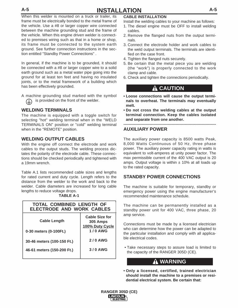
Table A.1 lists recommended cable sizes and lengthsfor rated current and duty cycle. Length refers to thedistance from the welder to the work and back to thewelder. Cable diameters are increased for long cablelengths to reduce voltage drops.
TABLE A-1
TOTAL COMBINED LENGTH OFELECTRODE AND WORK CABLES
Cable Length
0-30 meters (0-100Ft.)
30-46 meters (100-150 Ft.)
46-61 meters (150-200 Ft.)
Cable Size for 305 Amps
100% Duty Cycle1 / 0 AWG
2 / 0 AWG
3 / 0 AWG
CAUTION
WARNING
A-6INSTALLATION
RANGER 305D
A-6
Connection of the LN-25 to the RANGER 305D(CE)Shut off welder before making any electrical con-nections.------------------------------------------------------------------------The LN-25 with or without an internal contactor maybe used with the RANGER 305D (CE). See the appro-priate connection diagram in Section F.NOTE: The LN-25 (K431) Remote Control Moduleand (K432) Remote Cable are not recommended foruse with the RANGER 305D (CE).
1. Shut the welder off.
2. For electrode Positive, connect the electrodecable from the LN-25 to the "+" terminal of thewelder and work cable to the "-" terminal of thewelder. For electrode Negative, connect the elec-trode cable from the LN-25 to the "-" terminal ofthe welder and work cable to the "+" terminal ofthe welder.
3. Attach the single lead from the front of the LN-25to work using the spring clip at the end of the lead.This is a control lead to supply current to the wirefeeder motor; it does not carry welding current.
4. Set the MODE switch to the "CV-WIRE " position.
5. Set the "WELD TERMINALS" switch to "WELDTERMINALS ON"
6. Set the "ARC CONTROL" knob to "0" initially andadjust to suit.
7. Set the "IDLE" switch to the "AUTO" position.When not welding, the RANGER 305D (CE)engine will be at the low idle speed. If you areusing an LN-25 with an internal contactor, theelectrode is not energized until the gun trigger isclosed.
8. When the gun trigger is closed, the current sensingcircuit will cause the RANGER 305D (CE) engineto go to the high idle speed, the wire will begin tofeed and the welding process started. When weld-ing is stopped, the engine will revert to low idlespeed after approximately 12 seconds unlesswelding is resumed.
If you are using an LN-25 without an internal con-tactor, the electrode will be energized when theRANGER 305D (CE) is started.------------------------------------------------------------------------
WARNING
CAUTION
• The installation complies with the NationalElectrical Code and all other applicable electri-cal codes.
• The premises is isolated and no feedback intothe utility system can occur. Certain laws requirethe premises to be isolated before the generatoris linked to the premises. Check your localrequirements.
-----------------------------------------------------------------------CONNECTION OF LINCOLN ELECTRICWIRE FEEDERSConnection of LN-15 to the Ranger 305DThese connections instructions apply to both the LN-15 Across The-Arc and Control Cable models. TheLN-15 has an internal contactor and the electrode isnot energized until the gun trigger is closed. When thegun trigger is closed the wire will begin to feed and thewelding process is started.
• Shut the welder off.
• For electrode Positive, connect the electrode cableto the "+" terminal of the welder and work cable tothe "-" terminal of the welder. For electrodeNegative, connect the electrode cable "-" terminalof the welder and work cable to the "+" terminal ofthe welder.
• Across The-Arc Model:
Attach the single lead from the front of the LN-15 towork using the spring clip at the end of the lead. Thisis a control lead to supply current to the wire feedermotor; it does not carry welding current.
Set the "WELD TERMINALS" switch to "WELD TER-MINALS ON".
• Control Cable Model:
Connect Control Cable between Engine Welder andFeeder.
Set the MODE switch to the "CV-WIRE " position.
Set the "WELD TERMINALS" switch to "REMOTELYCONTROLLED".
Set the "WIRE FEEDER VOLTMETER" switch toeither "+" or "-" as required by the electrode polaritybeing used.
Set the "ARC CONTROL" knob to "0" initially andadjust to suit.
Set the "IDLE" switch to the "AUTO" position. 0

A-7INSTALLATION
RANGER 305D (CE)
A-7
Connection of LN-742 and Cobramatic to RANGER305D (CE)
• Shut the welder off.
• Connect per instructions on the appropriate connec-tion diagram in Section F.
Connection of PRINCE XL SPOOL GUN to theRANGER 305D (CE)
Connection of the Prince XL Spool Gun requires theuse of the K1849-1 Adapter Module.
• Shut the Welder off.
• For electrode Positive, connect the electrode cableto the "+" terminal of the welder and work cable tothe "-" terminal of the welder. For electrodeNegative, connect the electrode cable "-" terminal ofthe welder and work cable to the "+" terminal of thewelder.
• Connect the Control Cable of the Spool Gun to theAdapter Module and connect the Control Cable ofthe Adapter Module to the Welder.
• Connect the Gas Hose.
• Set the MODE switch to the "CV-WIRE " position.
• Set the "WELD TERMINALS" switch to "WELDTERMINALS ON".
• Set the "ARC CONTROL" knob to "0" initially andadjust to suit.
• Set the “IDLE” switch to the “HIGH” position.

B-1OPERATION
RANGER 305D (CE)
B-1
SAFETY PRECAUTIONS
Do not attempt to use this equipment until youhave thoroughly read the engine manufacturer’smanual supplied with your welder. It includesimportant safety precautions, detailed enginestarting, operating and maintenance instructions,and parts lists.------------------------------------------------------------------------
ELECTRIC SHOCK can kill.• Do not touch electrically live parts or
electrode with skin or wet clothing.• Insulate yourself from work and
ground• Always wear dry insulating gloves.
• Always operate the welder with the hinged doorclosed and the side panels in place.
• Read carefully the Safety Precautions pagebefore operating this machine. Always followthese and any other safety procedures includedin this manual and in the Engine InstructionManual.
GENERAL DESCRIPTION
The RANGER 305D (CE) is a diesel engine poweredDC multi-process welding power source and ACpower generator. The engine drives a generator thatsupplies three phase power for the DC welding circuitand three phase and single phase power for the ACauxiliary outlets. The DC welding control system usesstate of the art Chopper Technology (CT TM) for supe-rior welding performance.
FOR AUXILIARY POWER:
Start the engine and set the IDLER control switch tothe desired operating mode. Full power is availableregardless of the welding control settings providing nowelding current is being drawn.
ENGINE OPERATIONBefore Starting the Engine:
• Be sure the machine is on a level surface.• Open top & side engine doors and remove the
engine oil dipstick and wipe it with a clean cloth.Reinsert the dipstick and check the level on the dip-stick.
• Add oil (if necessary) to bring the level up to the fullmark. Do not overfill. Close engine door.
• Check radiator for proper coolant level. (Fill if nec-essary).
• See Engine Owner’s Manual for specific oil andcoolant recommendations.
ADD FUEL
• Stop engine while fueling.• Do not smoke when fueling.• Keep sparks and flame away
from tank.• Do not leave unattended while
fueling.• Wipe up spilled fuel and allow
fumes to clear before startingengine.
• Do not overfil l tank, fuelexpansion may cause over-flow.DIESEL FUEL ONLY
------------------------------------------------------------------------• Remove the fuel tank cap.
• Fill the tank approximately 4 inches (100mm) fromthe top of the filler neck to allow for fuel expansion(observe the fuel gauge while filling). DO NOT FILLTHE TANK TO THE POINT OF OVERFLOW.
• Replace the fuel cap and tighten securely.
• See Engine Owner’s Manual for specific fuel recom-mendations.
BREAK-IN PERIOD
Any engine will use a small amount of oil during its“break-in” period. For the diesel engine on theRANGER 305D (CE), break-in is about 50 runninghours.
Check the oil every four hours during break-in.Change the oil after the first 50 hours of operation,every 100 hours thereafter. Change the oil filter at thesecond oil change.
During break-in, subject the RANGER 305D (CE)to moderate loads. Avoid long periods running atidle. Before stopping the engine, remove all loadsand allow the engine to cool several minutes.------------------------------------------------------------------------
WARNING
WARNING
CAUTION
DIESEL FUELcan cause fire.

B-2OPERATIONB-2
WELDING CONTROLS (Figure B.1)
1. OUTPUT CONTROL: The OUTPUT dial isused to preset the output voltage or current as dis-played on the digital meters for the four weldingmodes. When in the CC-STICK, DOWNHILL PIPEor CV-WIRE modes and when a remote control isconnected to the 6-Pin or 14-Pin Connector, theauto-sensing circuit automatically switches theOUTPUT CONTROL from control at the welder tothe remote control.
In the CV-WIRE mode, if the wire feeder has volt-age control capability, when the control cable isconnected to the 14-Pin Connector, the auto-sens-ing circuit automatically makes OUTPUT CON-TROL inactive and the wire feeder voltage controlactive.
When in the TOUCH START TIG mode and when aAmptrol is connected to the 6-Pin Connector, theOUTPUT control is used to set the maximum cur-rent range of the CURRENT CONTROL of theAmptrol.
2. DIGITAL OUTPUT METERSThe digital meters allow the output voltage (CV-WIRE mode) or current (CC-STICK, PIPE and TIGmodes) to be set prior to welding using the OUT-PUT control dial. During welding, the meter displaythe actual output voltage (VOLTS) and current(AMPS). A memory feature holds the display ofboth meters on for seven seconds after welding isstopped. This allows the operator to read the actu-al current and voltage just prior to when weldingwas ceased.
While the display is being held the left-most deci-mal point in each display will be flashing. Theaccuracy of the meters is +/- 3%.
3. WELD MODE SELECTOR SWITCH:(Provides four selectable welding modes)CV-WIREDOWNHILL PIPECC-STICKTOUCH START TIG
RANGER 305D (CE)
1
10
7
4
9
5
8
11
12
13
6
15
14
17
16
2
3
FIGURE B.1
B-3OPERATIONB-3
4. ARC CONTROL: The ARC CONTROL dial is active inthe CV-WIRE, CC-STICK and DOWNHILL PIPE modes,and has different functions in these modes. This control isnot active in the TIG mode.
CC-STICK mode: In this mode, the ARC CONTROL dialsets the short circuit current (arc-force) during stick weldingto adjust for a soft or crisp arc. Increasing the dial from –10(soft) to +10 (crisp) increases the short circuit current andprevents sticking of the electrode to the plate while welding.This can also increase spatter. It is recommended that theARC CONTROL be set to the minimum number withoutelectrode sticking. Start with a setting at 0.
DOWNHILL PIPE mode: In this mode, the ARC CONTROLdial sets the short circuit current (arc-force) during stickwelding to adjust for a soft or a more forceful digging arc(crisp). Increasing the number from –10 (soft) to +10 (crisp)increases the short circuit current which results in a moreforceful digging arc. Typically a forceful digging arc is pre-ferred for root and hot passes. A softer arc is preferred forfill and cap passes where weld puddle control and deposi-tion ("stacking" of iron) are key to fast travel speeds. It isrecommended that the ARC CONTROL be set initially at 0.
CV-WIRE mode: In this mode, turning the ARC CONTROLclock wise from –10 (soft) to +10 (crisp) changes the arcfrom soft and washed-in to crisp and narrow. It acts as aninductance/pinch control. The proper setting depends onthe procedure and operator preference. Start with a settingof 0.
5. WELD OUTPUT TERMINALS WITH FLANGENUT: Provides a connection point for the electrode andwork cables.
6. GROUND STUD: Provides a connection point for connecting the machinecase to earth ground.
7. 14-PIN CONNECTOR: For attaching wire feeder con-trol cables to the RANGER 305D (CE). Includes contactorclosure circuit, auto-sensing remote control circuit, and 42Vpower. The remote control circuit operates the same as the6 Pin connector.Note: The 14-pin connector does not include 120V.
8. 6-PIN CONNECTOR: For attaching optional remotecontrol equipment. Includes auto-sensing remote controlcircuit.
9. WELD TERMINALS SWITCH: In the WELD TERMI-NALS ON position, the output is electrically hot all the time.In the REMOTELY CONTROLLED position, the output iscontrolled by a wire feeder or amptrol device, and is electri-cally off until a remote switch is depressed.
10. WIRE FEEDER VOLTMETER SWITCH:Matches the polarity of the wire feeder voltmeter to thepolarity of the electrode.
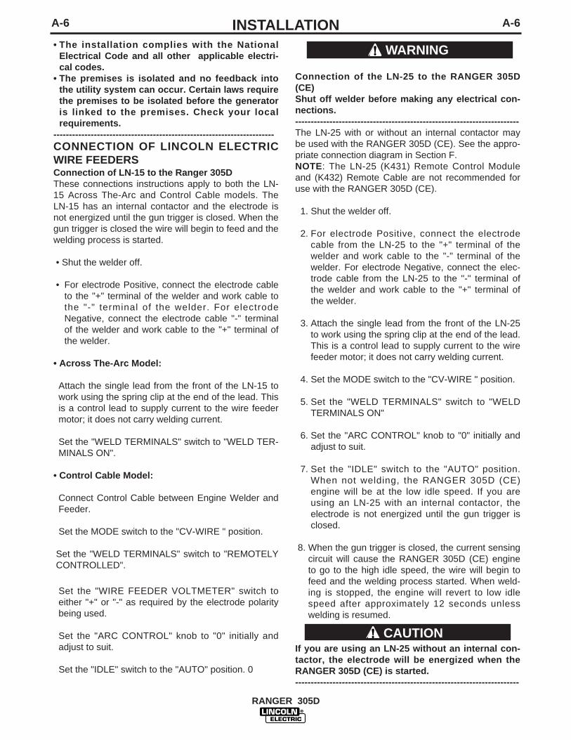
ENGINE CONTROLS: (Figure B.2)
11. RUN/STOP SWITCH - RUN position energizes theengine prior to starting. STOP position stops the engine.The oil pressure interlock switch prevents battery drain ifthe switch is left in the RUN position and the engine is notoperating.
12. GLOW PLUG PUSH BUTTON -• When pushed activates the glow plugs as well as
the electric fuel pump for quick starting. Glow plugshould not be activated for more than 20 secondscontinuously.(For Codes 11122, 11123 )
• AUTO BLEED FUNCTION – Air will automaticallybleed from the fuel system by simply pushing theGLOW PLUG BUTTON. It is generally not requiredto crack open fittings in the fuel system to bleed airfrom the fuel system.(For Codes 11122, 11123)
• When pushed activates the glow plugs. Glow plugshould not be activated for more than 20 secondscontinuously.(For Codes 11189, 11190)
13. START PUSH BUTTON -Energizes the starter motor to crank engine.
14. IDLER SWITCH- Has two positions as follows:1) In the HIGH position, the engine runs at the high idle
speed controlled by the engine governor.2) In the AUTO position, the idler operates as follows:
• When switched from HIGH to AUTO or after starting theengine, the engine will operate at full speed for approxi-mately 12 seconds and then go to low idle speed.
• When the electrode touches the work or power is drawnfor lights or tools (approximately 100 Watts minimum), theengine accelerates and operates at full speed.
• When welding ceases or the AC power load is turned off,a fixed time delay of approximately 12 seconds starts. Ifthe welding or AC power load is not restarted before theend of the time delay, the idler reduces the engine speedto low idle speed.
• The engine will automatically return to high idle speedwhen there is welding load or AC power load reapplied.
RANGER 305D (CE)

B-4OPERATIONB-4
15. ELECTRIC FUEL GAUGE- Provides accu-rate, reliable indication of how much fuel is in thetank
.16. ENGINE HOUR METER – Displays the total
time that the engine has been running. This meteris useful for scheduling prescribed maintenance.
17. ENGINE PROTECTION LIGHT-A warningindicator light for Low Oil Pressure and/or CoolantOver Temperature. The light is off when the sys-tems are functioning properly. The light turns onwhen the RUN-STOP switch is in the “ON” posi-tion prior to starting the engine. If the EngineProtection or Battery Charging Lights do “not”turn off shortly after starting the engine shut offthe engine immediately and determine the cause.
STARTING THE ENGINE1. Remove all plugs connected to the AC power
receptacles.
2. Set IDLER switch to AUTO.
3. Set the RUN/STOP switch to RUN.
4. Press Glow Plug Button and hold 5 to 10 seconds.
5. Press and hold both the “Glow Plug” Button andSTART button together until the engine starts or forup to 10 seconds.
6. Release the engine START button immediatelywhen the engine starts.
7. Release the glow plug button after the EngineProtection Light turns off or after an additional 5seconds maximum.
8. The engine will run at high idle speed for approxi-mately 12 seconds and then drop to low idle speed.Allow the engine to warm up at low idle for severalminutes before applying a load and/or switching tohigh idle. Allow a longer warm up time in coldweather.
NOTE: If the unit fails to start repeat step 4 throughstep 7 after waiting 30 seconds
• Do not allow the starter motor to run continuouslyfor more than 20 seconds.
• Do not push the START button while the engineis running because this can damage the ringgear and/or the starter motor.
• IF the Engine Protection or Battery ChargingLights do “not” turn off shortly after starting theengine shut off the engine immediately and determine the cause.
-----------------------------------------------------------------------NOTE: When starting a RANGER 305D (CE) for thefirst time, or after and extended period of time of notoperating, it will take longer than normal because thefuel pump has to fill the fuel system.
STOPPING THE ENGINERemove all welding and auxiliary power loads andallow the engine to run at low idle speed for a fewminutes to cool the engine.
STOP the engine by placing the RUN-STOP switch inthe STOP position.
NOTE: A fuel shut off valve is located on the fuel pre-filter. Turn on Fuel shut-off valve on the fuel pre-filter.
RANGER 305D (CE)
CAUTION
TYPICAL RANGER 305D (CE) FUEL CONSUMPTIONKubota D722 Running time forLiters/Hr (Gal./Hr) 45 Liters/hours
Low Idle - No Load2200 R.P.M. .92 (.24) 49.38High Idle - No Load3100 R.P.M. 1.62 (.43) 28.07DC Weld Output250 Amps @ 30 Volts 3.42 (.90) 13.30DC Weld Output225 Amps @ 25 Volts 2.92 (.77) 15.55
8,000 Watts, 3 PHASE 3.35 (.89) 13.54
5,000 Watts, 3 PHASE 2.65 (.70) 17.12
3,000 Watts, 3 PHASE 2.19 (.58) 20.78
TABLE B.1

TYPICAL CURRENT RANGES (1) FOR TUNGSTEN ELECTRODES(2)
Tungsten Electrode DCEN (-) DCEP (+) Approximate Argon Gas Flow TIG TORCH
Diameter in. (mm) Flow Rate C.F.H. ( l /min.) Nozzle Size (4), (5)
1%, 2% Thoriated 1%, 2% Thoriated Aluminum Stainless SteelTungsten Tungsten
.010 (.25) 2-15 (3) 3-8 (2-4) 3-8 (2-4) #4, #5, #60.020 (.50) 5-20 (3) 5-10 (3-5) 5-10 (3-5)0.040 (1.0) 15-80 (3) 5-10 (3-5) 5-10 (3-5)
1/16 (1.6) 70-150 10-20 5-10 (3-5) 9-13 (4-6) #5, #6
3/32 (2.4) 150-250 15-30 13-17 (6-8) 11-15 (5-7) #6, #7, #81/8 (3.2) 250-400 25-40 15-23 (7-11) 11-15 (5-7)
5/32 (4.0) 400-500 40-55 21-25 (10-12) 13-17 (6-8) #8, #103/16 (4.8) 500-750 55-80 23-27 (11-13) 18-22 (8-10)1/4 (6.4) 750-1000 80-125 28-32 (13-15) 23-27 (11-13)
(1) When used with argon gas. The current ranges shown must be reduced when using argon/helium or pure helium shielding gases.(2) Tungsten electrodes are classified as follows by the American Welding Society (AWS):
Pure EWP1% Thoriated EWTh-12% Thoriated EWTh-2
Though not yet recognized by the AWS, Ceriated Tungsten is now widely accepted as a substitute for 2% Thoriated Tungsten in AC and DC applications.(3) DCEP is not commonly used in these sizes.(4) TIG torch nozzle "sizes" are in multiples of 1/16ths of an inch:
# 4 = 1/4 in. (6 mm)# 5 = 5/16 in. (8 mm)# 6 = 3/8 in. (10 mm)# 7 = 7/16 in. (11 mm)# 8 = _ in. (12.5 mm)#10 = 5/8 in. (16 mm)
(5) TIG torch nozzles are typically made from alumina ceramic. Special applications may require lava nozzles, which are less prone to breakage, but cannot withstand high temperaturesand high duty cycles.
B-5OPERATIONB-5
WELDER OPERATIONDUTY CYCLE
Duty Cycle is the percentage of time the load is beingapplied in a 10 minute period. For example a 60% dutycycle, represents 6 minutes of load and 4 minutes of noload in a 10 minute period.
The RANGER 305D (CE) can be used with a broad rangeof DC stick electrodes. The MODE switch provides twostick welding settings as follows:
CONSTANT CURRENT (CC-STICK) WeldingThe CC-STICK position of the MODE switch is designed forhorizontal and vertical-up welding with all types of elec-trodes, especially low hydrogen.
The OUTPUT CONTROL dial adjusts the full output rangefor stick welding.
The ARC CONTROL dial sets the short circuit current (arc-force) during stick welding to adjust for a soft or crisp arc.Increasing the dial from –10 (soft) to +10 (crisp) increasesthe short circuit current and prevents sticking of the elec-trode to the plate while welding. This can also increasespatter. It is recommended that the ARC CONTROL be setto the minimum number without electrode sticking. Startwith a setting at 0.
DOWNHILL PIPE (STICK) WeldingThe DOWNHILL PIPE position of the MODE switch is aslope controlled setting intended for "out-of-position" and"down hill" pipe welding where the operator would like tocontrol the current level by changing the arc length.
The OUTPUT CONTROL dial adjusts the full output rangefor stick welding. The ARC CONTROL dial sets the shortcircuit current (arc-force) during stick welding to adjust fora soft or a more forceful digging arc(crisp). Increasing thenumber from –10 (soft) to +10 (crisp) increases the shortcircuit current which results in a more forceful digging arc.Typically a forceful digging arc is preferred for root and hotpasses. A softer arc is preferred for fill and cap passeswhere weld puddle control and deposition ("stacking" ofiron) are key to fast travel speeds. It is recommended thatthe ARC CONTROL be set initially at 0.
TIG WELDING
The TOUCH START TIG setting of the MODE switch is forDC TIG (Tungsten Inert Gas) welding. To initiate a weld,the OUTPUT CONTROL dial is first set to the desired cur-rent and the tungsten is touched to the work. During thetime the tungsten is touching the work there is very littlevoltage or current and, in general, no tungsten contamina-tion. Then, the tungsten is gently lifted off the work in arocking motion, which establishes the arc.
To stop the arc, simply lift the TIG torch away from thework piece. When the arc voltage reaches approximately30 volts, the arc will go out and the machine will automati-cally reset to the touch start current level. The tungstenmay then be retouched to the work piece to restrike thearc. The arc may also be started and stopped with anAmptrol or Arc Start Switch. See the following para-graphs.
RANGER 305D (CE)
TABLE B.2

AUXILIARY POWER:
Start the engine and set the IDLER control switch tothe desired operating mode. Full power is availableregardless of the welding control settings providing nowelding current is being drawn.
Simultaneous Welding and Auxiliary Power Loads
While welding, the amount of 3-phase Auxiliary poweravailable is reduced. (See table A.4)
RANGER 305D (CE)
B-6OPERATIONB-6
When in the TOUCH START TIG mode and when aAmptrol is connected to the 6-pin Connector the OUT-PUT dial is used to set the maximum current range ofthe CURRENT CONTROL of the Amptrol.
The ARC CONTROL is not active in the TIG mode.
The RANGER 305D (CE) can be used in a wide varietyof DC TIG welding applications. In general the ‘TouchStart’ feature allows contamination free starting withoutthe use of a Hi-frequency unit. If desired, the K930-2TIG Module can be used with the RANGER 305D (CE).The settings are for reference.
RANGER 305D (CE) settings when using the K930-2TIG Module with an Amptrol or Arc Start Switch:
• Set the MODE Switch to the TOUCH START TIGsetting.
• Set the "IDLER" Switch to the "AUTO" position.• Set the "WELDING TERMINALS" switch to the
"REMOTELY CONTROLLED" position. This will keepthe "Solid State" contactor open and provide a “cold”electrode until the Amptrol or Arc Start Switch ispressed
When using the TIG Module, the OUTPUT control onthe RANGER 305D (CE) is used to set the maximumrange of the CURRENT CONTROL on the TIG moduleor an Amptrol if connected to the TIG Module. (SeeTable B.2.)
WIRE WELDING-CVConnect a wire feeder to the Ranger 305D according tothe instructions in INSTALLATION INSTRUCTIONSSection.
The RANGER 305D (CE) in the CV-WIRE mode, per-mits it to be used with a broad range of flux cored wire(Innershield and Outershield) electrodes and solid wiresfor MIG welding (gas metal arc welding). Welding canbe finely tuned using the ARC CONTROL. Turning theARC CONTROL clockwise from –10 (soft) to +10 (crisp)changes the arc from soft and washed-in to crisp andnarrow. It acts as an inductance/pinch control. Theproper setting depends on the procedure and operatorpreference. Start with the dial set at 0.
For any electrodes the procedures should be keptwithin the rating of the machine. For additional elec-trode information see WWW.Lincolnelectric.com orthe appropriate Lincoln publication.
ARC GOUGINGThe RANGER 305D (CE) can be used for limited arcgouging. For optimal performance, set the MODEswitch to CC-STICK and the ARC CONTROL to +10.
Set the OUTPUT CONTROL knob to adjust outputcurrent to the desired level for the gouging electrodebeing used according to the ratings in the following
Table B.3.
Carbon Diameter Current Range (DC, electrodepositive)
1/8" 60-90 Amps
5/32" 90-150 Amps
3/16" 200-250 Amps
TABLE B.3
WELDING OUTPUT-AMPS
050100150200250
PERMISSIBLE POWER-WATTS(UNITY POWER FACTOR)
80006500500035002000
0
PERMISSIBLE AUXPOWER @400V, 3PHASE
12 Amps9 Amps7 Amps5 Amps3 Amps0 Amps
TABLE A.4

C-1ACCESSORIESC-1
FIELD INSTALLED OPTIONS /ACCESSORIES
K1898-1 SPARK ARRESTOR - Mounts between muf-fler & elbow to eliminate any risk of spark from exhaust.
K704 ACCESSORY SET - Includes (10m) 35 ft. ofelectrode cable and (9.m) 30 ft. of work cable, head-shield, work clamp electrode holder. Cables are ratedat 400 amps, 100% duty cycle.
K857 (7.6m) 25 ft. or K857-1 (30.4m) 100 ft.REMOTE CONTROL - Portable control provides samedial range as the output control on the welder. Has aconvenient 6 pin plug for easy connection to thewelder.
RANGER 305D (CE)

D-1MAINTENANCED-1
RANGER 305D (CE)
SAFETY PRECAUTIONS
• Have qualified personnel do all maintenanceand troubleshooting work.
• Turn the engine off before working inside themachine or servicing the engine.
• Remove guards only when necessary toperform maintenance and replace them whenthe maintenance requiring their removal iscomplete. If guards are missing from themachine, obtain replacements from a LincolnDistributor. (See Operating Manual Parts List.)
• Read the Safety Precautions in the front of thismanual and in the Engine Owner’s Manual beforeworking on this machine.
• Keep all equipment safety guards, covers, anddevices in position and in good repair. Keephands, hair, clothing, and tools away from thegears, fans, and all other moving parts whenstarting, operating, or repairing the equipment.
Routine Maintenance
At the end of each day’s use, refill the fuel tank tominimize moisture condensation in the tank. Runningout of fuel tends to draw dirt into the fuel system.Also, check the crankcase oil level and add oil ifindicated.
WARNINGFREQUENCY
DAILY OR BEFORE STARTING ENGINE
MAINTENANCE REQUIRED • FILL FUEL TANK.• CHECK OIL LEVEL.• CHECK COOLANT LEVEL.• CHECK AIR CLEANER ELE-
MENT AND HOUSING FORDIRTY, LOOSE OR DAMAGEDPARTS.
• CHECK AIR INTAKE HOSEFOR CRACKS OR LOOSECONNECTIONS.
• CHECK AIR INTAKE/EXHAUSTAREAS & RADIATOR FORDIRT. CLEAN AS NECESSARY.
• CHECK ALTERNATOR BELTTENSION AND WEAR.
ITEM MAKE AND PART NUMBER
OIL FILTER KUBOTA 70000-15241
AIR FILTER ELEMENT DONALDSON P822686
FUEL FILTER ELEMENT KUBOTA 15231-43560
BATTERY KUBOTA GROUP 58, 550 CCA
BELT KUBOTA 15881-97011
GLOW PLUGS KUBOTA 16851-65512
INLINE FUEL FILTER KUBOTA 12581-43012
ENGINE MAINTENANCE COMPONENTSKUBOTA D722 DIESEL ENGINE
KUBOTA D722 DIESEL ENGINE
Service IntervalsObserve the following for service and maintenance. The lubricatingoil change intervals listed in the table below are for Classes CF,CEand CD lubricating oils of API classification with a low sulfur fuel inuse. If the CF-4 or CG-4 lubricating oil is used with a high-sulfurfuel, change the lubricating oil at shorter intervals than recommend-ed in the table below depending on the operating condition.
Every 50 hoursEvery 75 hours
Every 100 hours
Every 150 hours
Every 200 hoursEvery 400 hoursEvery 500 hours
Every 1 or 2 monthsEvery 800 hoursEvery 1500 hours
Every 3000 hours
Every 2 years
Check of fuel lines and clamp bands.Change of engine oil
Inspect/Clean air cleaner elementand Vacuator™ valve.Cleaning of fuel filter.Check the battery electrolyte level.Check the fan belt tightness.Check the radiator and hose clamps.Replacement of oil filter cartridge Check the intake air lines.Replacement of Air Filter element. Replacement of fuel filter element.Removal of of sediment in fuel tank.Cleaning of water jacket (radiatorinterior).Replacement of fan belt.Recharging of Battery.Check of valve clearance.Check the fuel injection nozzle injec-tion pressure.Check of injection pump.Check of fuel injector timer.Replacement of batteryReplacement of radiator hoses andclamp band.Replacement of fuel pipes andclamps.Change the radiator coolant.(L.L.C.)Replacement of intake air line.
•
*1
•
*1,*2
*3*3
*3*3
*4
Intervals Items
IMPORTANT
• These jobs should be done after the first 50 hours of operation.
*1 Air cleaner should be inspected/cleaned more often in dusty conditions thanthe normal conditions.
*2 Follow Service Instructions and Installation Tips for air cleaner inSection D.
*3 Consult your local KUBOTA Dealer for this service.*4 Replace only if necessary.
Please see Engine Owners Manual for Warranty Statement in detail.

D-2MAINTENANCED-2
ENGINE OIL CHANGEDrain the engine oil while the engine is warm toassure rapid and complete draining. It is recommend-ed that each time the oil is changed the oil filter bechanged as well.
• Be sure the unit is off. Disconnect the negative bat-tery cable to ensure safety.
• Locate oil drain hose and valve in bottom of baseand pull through the hole in the battery access panelon the welder.
• Remove the cap from the drain valve. Push valve inand twist counterclockwise. Pull to open and drainthe oil into a suitable container for disposal.
• Close the drain valve by pushing in and twistingclockwise. Replace the cap.
• Re-fill the crankcase to the upper limit mark on thedipstick with the recommended oil (see engine oper-ation manual OR engine service items decal ORbelow). Replace and tighten the oil filler cap secure-ly.
• Push oil drain hose and valve back into unit, re-con-nect negative battery cable, and close doors andengine top cover before restarting unit.Wash yourhands with soap and water after handling usedmotor oil. Please dispose of used motor oil in amanner that is compatible with the environment.We suggest you take it in a sealed container to yourlocal service station or recycling center for reclama-tion. DO NOT throw it in the trash; pour it on theground or down a drain.
ENGINE OIL REFILL CAPACITIESWithout oil filter replacement: • 3.2 liter (3.3 U.S. Quart)
With oil filter replacement:• 3.2 liter ( 3.4 U.S. Quart.)
Use motor oil designed for diesel engines that meetsrequirements for API service classif icationCC/CD/CE/CF/CF-4/CG-4 or CH-4.ACEA E1/E2/E3. Always check the API service labelon the oil container to be sure it includes the lettersindicated. (Note: An S-grade oil must not be used in adiesel engine or damage may result. It IS permissibleto use an oil that meets S and C grade service classifi-cations.)SAE 10W30 is recommended for general, all tempera-ture use, -15C to 40C (5F to 104F).See engine owner’s manual for more specific informa-tion on oil viscosity recommendations.
OIL FILTER CHANGE• Drain the oil.
• Remove the oil filter with an oil filter wrench anddrain the oil into a suitable container. Discard theused filter. Note: Care should be taken during filterremoval to not disrupt or damage in any way the fuellines.
• Clean the filter mounting base and coat the gasketof the new filter with clean engine oil.
• Screw the new filter on by hand until the gasket con-tacts the mounting base. Using an oil filter wrench,tighten the filter an additional 1/2 to 7/8 of a turn.
• Refill the crankcase with the specified amount of therecommended engine oil. Reinstall the oil filler capand tighten securely.
• Start the engine and check for oil filter leaks.
• Stop the engine and check the oil level. If neces-sary, add oil to the upper limit mark on the dipstick.
• Never use gasoline or low flash point solventsfor cleaning the air cleaner element. A fire orexplosion could result.
• Never run the engine without the air cleaner.Rapid engine wear will result from contaminants,such as dust and dirt being drawn into theengine.
------------------------------------------------------------------------AIR CLEANER
The diesel engine is equipped with a dry type air filter.Never apply oil to it. Service the air cleaner as follows:
Replace the element at least every 200 hours ofoperation and sooner under dusty conditions.
RANGER 305D (CE)
CAUTION
WARNING

D-3MAINTENANCED-3
RANGER 305D (CE)
Service Instructions & Installation TipsFor Engine Air Filter
Release the1Seal CarefullyUnlatch and remove the servicecover of the air cleaner. Makecertain the latches are foldedback against the cover so thatthey donít hinder filterremoval/installation. Most latchesare spring loaded to fold back when open.The filter fits tightly over the outlet tube,creating the critical seal on the insidediameter of the filter endcap. The filtershould be removed gently to reduce theamount of dust dislodged. There will besome initial resistance, similar to breakingthe seal on a jar. Gently move the end of thefilter back and forth to break the seal.
Avoid Dislodging2Dust from the FilterGently pull thefilter off the outlettube and out of thehousing. Avoidknocking the filteragainst the housing.
Clean Sealing Surface3of the Outlet TubeUse a clean cloth to wipe the sealingsurface. Dust on the outside diameter of the
outlet tube could hinderan effective sealand cause leakage.Make sure that allcontaminant isremoved before the
new filter is inserted.
Insert the New7RadialSealô Filterby HandInsert carefully. Seat the new filter by hand,making certain it is completely into the aircleaner housing before latching the cover inplace. If the cover hits the filter before it isfully in place, remove the cover and push(by hand) thefilter further intothe air cleanerand try again.The covershould go onwith no extra force.
Never use the latches on the cover to forcethe filter into the air cleaner! It is temptingto assume the cover will do the job ofseating the filter ñ but it will not! Using thelatches to push the filter in could causedamage to the housing and will void thewarranty.
Donaldson filters with RadialSeal™ SealingTechnology are self-aligning, self-centering,and self-sealing. A new filter has a drylubricant to aid installation. The criticalsealing area will stretch slightly, adjustitself and distribute the sealing pressureevenly. To complete a tight seal, applypressure by hand at the outer rim of thefilter, not the flexible center. (Avoidpushing on the center of the urethane endcap.) No cover pressure is required to holdthe seal. Again, do NOT use the servicecover to push the filter into place!
When the filter in is place, put the servicecover back on, making sure the Vacuator™
Valve points down. Inspect the VacuatorValve for cracks or dust hang-ups to insurethat it is functioning properly. Re-fasten the latches.
Check Connections8for Tight FitMake sure that all clamps, bolts, andconnections in the entire air intake systemare tight. Check for holes in piping, andrepair if needed.
Clean the Inside of4the Outlet TubeCarefully wipe the insideof the outlet tubewith a clean cloth.Dirt accidentlytransferred to theinside of the outlettube will reach theengine and cause wear.(Engine manufacturers says that it takesonly a few grams of dirt to ëdustí anengine!) Be careful not to damage thesealing area on the tube.
Check the Old5Filter for Leak CluesVisually inspect the old filter for any signsof leaks. A streak of dust onthe clean side of the filteris a telltale sign.Remove any causeof leaks beforeinstalling new
filter.
Inspect the New6Filter for DamageInspect the new filter carefully,
paying attention to the inside ofthe open end,
which is thesealing area.
NEVER installa damaged filter.
™

D-4MAINTENANCED-4
COOLING SYSTEM
HOT COOLANT can burn skin.
• Do not remove cap if radiator ishot.
------------------------------------------------------------------------Check the coolant level by observing the level in theradiator and recovery bottle. Add 50/50 antifreeze /water solution if the level is close to or below the"LOW" mark. do not fill above the "FULL" mark.Remove radiator cap and add coolant to radiator. Fillup to the top of the tube in the radiator filler neckwhich includes a connecting hose coming from thethermostat housing.
To drain the coolant, open the valve of the radiator.Open the radiator cap to allow complete drainage.(Tighten the valve and refi l l with a 50/50antifreeze/water solution.) Use an automotive grade(low silicate) ethylene glycol antifreeze. The coolingsystem capacity is 3.6L (3.85 quarts). Squeezeupper and lower radiator hoses while filling to bleed airfrom system coolant. Replace and tighten the radiatorcap.
Always premix the antifreeze and clean tap waterbefore adding to the radiator. It is very importantthat a precise 50/50 solution be used with thisengine year round. This gives proper cooling dur-ing hot weather and freezing protection to -37° C(-34° F).
Cooling solution exceeding 50% ethylene glycolcan result in engine overheating and damage tothe engine. Coolant solution must be premixedbefore adding to radiator.------------------------------------------------------------------------
Periodically remove the dirt from the radiator fins.
Periodically check the fan belt and radiator hoses.Replace if signs of deterioration are found.
TIGHTENING THE FAN BELT
If the fan belt is loose, the engine can overheat andthe battery lose its charge. Check tightness by press-ing on the belt midway between the pulleys. It shoulddeflect about 6mm (.25 in) under a load of 9 Kg (20lbs).
FUEL
At the end of each day’s use, refill the fuel tank to min-imize moisture condensation and dirt contamination inthe fuel line. Do not overfill; leave room for the fuel toexpand.
Use only fresh, No. 2 grade DIESEL fuel. Do not usekerosene.
See the Engine Operator's Manual for instructions onreplacing the fuel filter.
BLEEDING THE FUEL SYSTEM
You may need to bleed air from the fuel system if thefuel filter or fuel lines have been detached, the fueltank has been ran empty or after periods of long stor-age. It is recommended that the fuel shutoff valve beclosed during periods of non-use.
(For Codes 11122, 11123)The Kubota D722 engine supplied with this welder isequipped with an automatic bleeding mechanism thatfunctions when the electric fuel pump is actuated. It isgenerally not necessary to open a vent screw or fuelline fitting to bleed the fuel system.
(For Codes 11189, 11190)The Kubota D722 engine supplied with this welder isequipped with an automatic bleeding mechanism thathelps purge the air from the mechanical fuel pumpsystem. It is generally not necessary to open a ventscrew or fuel line fitting to bleed the fuel system.Operate the priming lever on the pump to assist start-ing after extended periods of non-use or out of fuelconditions.
To avoid personal injury, do not bleed a hotengine. This could cause fuel to spill onto a hotexhaust manifold, creating a danger of fire.------------------------------------------------------------------------Bleed the fuel system as follows:
1. Fill the fuel tank with fuel.2. Open the fuel shut off valve (vertical position of
handle) on the Fuel Filter.3. Press and hold the glow plug button for 10 to 20
seconds.(For Codes 11122, 11123)3a. Crank the engine by pressing the start button for
45 seconds. (For Codes 11189, 11190) 4. Check to see that fuel is flowing through both fuel
filters.5. Follow the normal STARTING procedures.
RANGER 305D (CE)
WARNING
CAUTION
WARNING

D-5MAINTENANCED-5
FUEL FILTER1. Check the fuel filter and fuel pre-filter for water
accumulation or sediment.
2. Replace the fuel filter if it is found with excessivewater accumulation or sediment. Empty fuel pre-fil-ter.
ENGINE ADJUSTMENTAdjustments to the engine are to be made only by aLincoln Service Center or an authorized Field ServiceShop.
BATTERY MAINTENANCETo access the battery, Disconnect the Negative andthen Positive battery cables. Remove the 4 screwsfrom the battery door using a screwdriver or a 10mmsocket. Remove the 2 nuts from the battery bracketusing a 11mm wrench or socket. Slide the battery outand remove from welder
GASES FROM BATTERY can explode.● Keep sparks, flame and cigarettes
away from battery.
To prevent EXPLOSION when:
● INSTALLING A NEW BATTERY — disconnectnegative cable from old battery first and con-nect to new battery last.
● CONNECTING A BATTERY CHARGER —remove battery from welder by disconnectingnegative cable first, then positive cable andbattery clamp. When reinstalling, connectnegative cable last. Keep well ventilated.
● USING A BOOSTER — connect positive lead tobattery first then connect negative lead to neg-
ative battery lead at engine foot.BATTERY ACID can burn eyes andskin.
● Wear gloves and eye protectionand be careful when working nearbattery.
● Follow instructions printed on battery.
RANGER 305D (CE)
OVERSPEED IS HAZARDOUSThe maximum allowable high idle speed for thismachine is 3150 RPM, no load. Do NOT tamperwith governor components or setting or make anyother adjustments to increase the maximumspeed. Severe personal injury and damage to themachine can result if operated at speeds abovemaximum.
CLEANING THE BATTERYKeep the battery clean by wiping it with a damp clothwhen dirty. If the terminals appear corroded, discon-nect the battery cables and wash the terminals with anammonia solution or a solution of 113g (1/4 pound) ofbaking soda and 0.9461L (1 quart) of water. Be surethe battery vent plugs (if equipped) are tight so thatnone of the solution enters the cells.After cleaning, flush the outside of the battery, the bat-tery compartment, and surrounding areas with clearwater. Coat the battery terminals lightly with petroleumjelly or a non-conductive grease to retard corrosion.Keep the battery clean and dry. Moisture accumula-tion on the battery can lead to more rapid dischargeand early battery failure.
CHECKING THE ELECTROLYTE LEVEL
If battery cells are low, fill them to the neck of the fillerhole with distilled water and recharge. If one cell islow, check for leaks.
CHARGING THE BATTERYWhen you charge, jump, replace, or otherwise con-nect battery cables to the battery, be sure the polarityis correct. Improper polarity can damage the chargingcircuit. The RANGER 305D (CE) positive (+) batteryterminal has a red terminal cover.
If you need to charge the battery with an externalcharger, disconnect the negative cable first, then thepositive cable before you attach the charger leads.After the battery is charged, reconnect the positivebattery cable first and the negative cable last. Failureto do so can result in damage to the internal chargercomponents.Follow the instructions of the battery charger manu-facturer for proper charger settings and charging time.
SERVICING OPTIONAL SPARKARRESTORClean every 100 hours.
WARNING
WARNING
• MUFFLER MAY BE HOT
• ALLOW ENGINE TO COOL BEFORE INSTALLINGTHE SPARK ARRESTER!
• DO NOT OPERATE ENGINE WHILE INSTALLINGTHE SPARK ARRESTER!
D-6MAINTENANCED-6
RANGER 305D (CE)
WELDER / GENERATORMAINTENANCE
STORAGE: Store the RANGER 305D (CE) in clean,dry protected areas.
CLEANING: Blow out the generator and controls peri-odically with low pressure air. Do this at least once aweek in particularly dirty areas.
BRUSH REMOVAL AND REPLACEMENT: It’s nor-mal for the brushes and slip rings to wear and darkenslightly. Inspect the brushes when a generator over-haul is necessary.
• Do not attempt to polish slip rings while theengine is running.
WARNING
• Service and Repair should only be performed byLincoln Electric Factory Trained Personnel.Unauthorized repairs performed on this equip-ment may result in danger to the technician andmachine operator and will invalidate your factorywarranty. For your safety and to avoid ElectricalShock, please observe all safety notes and pre-cautions.
CAUTION

E-1TROUBLESHOOTINGE-1
RANGER 305D (CE)
If for any reason you do not understand the test procedures or are unable to perform the tests/repairs safely, contact yourLocal Lincoln Authorized Field Service Facility for technical troubleshooting assistance before you proceed.
CAUTION
This Troubleshooting Guide is provided to help youlocate and repair possible machine malfunctions.Simply follow the three-step procedure listed below.
Step 1. LOCATE PROBLEM (SYMPTOM).Look under the column labeled “PROBLEM (SYMP-TOMS)”. This column describes possible symptomsthat the machine may exhibit. Find the listing thatbest describes the symptom that the machine isexhibiting.
Step 2. POSSIBLE CAUSE.The second column labeled “POSSIBLE CAUSE” liststhe obvious external possibilities that may contributeto the machine symptom.
Step 3. RECOMMENDED COURSE OF ACTIONThis column provides a course of action for thePossible Cause, generally it states to contact yourlocal Lincoln Authorized Field Service Facility.
If you do not understand or are unable to perform theRecommended Course of Action safely, contact yourlocal Lincoln Authorized Field Service Facility.
HOW TO USE TROUBLESHOOTING GUIDE
Service and Repair should only be performed by Lincoln Electric Factory Trained Personnel.Unauthorized repairs performed on this equipment may result in danger to the technician andmachine operator and will invalidate your factory warranty. For your safety and to avoid ElectricalShock, please observe all safety notes and precautions detailed throughout this manual.
__________________________________________________________________________
WARNING

E-2TROUBLESHOOTINGE-2
RANGER 305D (CE)
Observe all Safety Guidelines detailed throughout this manual
If for any reason you do not understand the test procedures or are unable to perform the tests/repairs safely, contact yourLocal Lincoln Authorized Field Service Facility for technical troubleshooting assistance before you proceed.
CAUTION
PROBLEMS(SYMPTOMS)
POSSIBLECAUSE
RECOMMENDEDCOURSE OF ACTION
Major Physical or Electrical Damageis Evident.
Engine will not "crank".
Engine will "crank" but not start.
Engine shuts down shortly afterstarting.
1. Contact your local LincolnAuthorized Field ServiceFacility.
1. Battery is low, Charge Battery.2. Loose battery cable connections.
Inspect, clean and tighten terminals.3. Faulty engine starter motor.
Contact authorized local EngineService Shop.
1. Fuel shut off valve on Main FuelFilter in the OFF position. Openvalve (vertical) position of handle.
2. Fuel Filters dirty/clogged. Checkand replace main filter elementand/or Inline Fuel Filter.
3. Out of fuel. Fill tank and bleed fuelsystem.
4. High coolant temperature or lowoil pressure. (indictor lights lit)Check oil and coolant levels. Fill ifrequired. Check for loose or bro-ken fan belt.
5. Faulty fuel shutdown solenoid.Check that shutdown solenoid isfunctioning properly and not bind-ing/ contact authorized engineservice shop.
6. Faulty fuel pump. Check for fuelf low through fi l ters. Contactauthorized local Engine ServiceShop.
1. High coolant temperature or lowoil pressure. (indictor light lit)Change oil and oil filters and fill toproper level. Check and fill coolantlevel. Check for loose or brokenfan belt. Start engine and look forleaks.
2. Faulty oil pressure switch or otherengine component. Contactauthorized local Engine ServiceShop.
3. Faulty engine protection relay.
If all recommended possible areasof misadjustment have beenchecked and the problem persists,Contact your local LincolnAuthorized Field Service Facility.

E-3TROUBLESHOOTINGE-3
RANGER 305D (CE)
Observe all Safety Guidelines detailed throughout this manual
If for any reason you do not understand the test procedures or are unable to perform the tests/repairs safely, contact yourLocal Lincoln Authorized Field Service Facility for technical troubleshooting assistance before you proceed.
CAUTION
PROBLEMS(SYMPTOMS)
POSSIBLECAUSE
RECOMMENDEDCOURSE OF ACTION
Engine shuts down while under aload.
Engine runs rough.
Battery does not stay charged.
Engine will not idle down to lowspeed.
Engine will not go to high idle whenattempting to weld.
1. High radiator coolant tempera-ture. Reduce load if it is exceed-ing machine rating. Add coolantto system if low. Clean fins onradiator if dirty. Tighten fan belt ifloose. Remove objects blockingor close to intake openings onboth sides of base and exhaustend (case back).
1. Dirty fuel or air filters. Inspect andclean/replace filters as needed.Inspect and clean/replace filtersas needed.
2. Water in fuel. If water found intank. Empty fuel tank and refillthen purge fuel lines.
1. Faulty battery. Replace.2. Loose connections at battery or
alternator. Clean and tighten con-nections.
3. Faulty engine alternator or charg-er module. Consult authorizedEngine Service Shop.
1. Idler switch in High idle position.Set switch to Auto.
2. External load on welder or auxil-iary power. Remove all externalloads.
3. Faulty PC board or idler sole-noid.
1. Poor work lead connection towork. Make sure work clamp istightly connected to clean basemetal.
2. "Contactor" switch is in wrongposition. Set to "Welding On" whenwelding without a control cable.Refer to Operations chapter for prop-er use of this switch.
3. Faulty PC board. Low idle speedset to low.
If all recommended possible areas ofmisadjustment have been checkedand the problem persists, Contactyour local Lincoln AuthorizedField Service Facility.

E-4TROUBLESHOOTINGE-4
RANGER 305D (CE)
Observe all Safety Guidelines detailed throughout this manual
If for any reason you do not understand the test procedures or are unable to perform the tests/repairs safely, contact yourLocal Lincoln Authorized Field Service Facility for technical troubleshooting assistance before you proceed.
CAUTION
PROBLEMS(SYMPTOMS)
POSSIBLECAUSE
RECOMMENDEDCOURSE OF ACTION
Engine will not go to high idle whenusing auxiliary power.
Engine wil l not go to high idleunder weld or auxiliary loading.
Engine does not develop fullpower. Engine runs rough.
Engine will not go to high idle whenattempting to weld or using auxil-iary power. Switching to manualhigh idle does not work.
Engine will not shut off.
Engine does not develop full power.Low weld and auxil iary output.Engine runs rough.
1. Auxiliary power load is less than100 watts. Idler may not respondwith less than a 100 watt load. Setidler to "High".
2. Faulty PC board.
1. Faulty idler solenoid. Check forbent linkage or broken spring
1. Fuel filter clogged, Replace.2. Air filter clogged, clean or replace.3. High idle setting incorrect, check
and adjust if required.4. Valves out of adjustment.5. Fuel contaminated with water or
sediment. Check fuel pre-filterand empty of water, bleed fuelsystem. Replace fuel in tank ifneeded.
1. Broken spring on Idle Solenoid,solenoid linkage binding, FaultyPC board, low idle speed set toolow on idle solenoid.
1. Fuel Shutdown solenoid notfunctioning properly / linkagebinding. Stop engine by shuttingoff valve located on main fuel fil-ter. Contact authorized localEngine Service Shop.
1. Fuel filter dirty/clogged. Replace.2. Air filter dirty/clogged. Replace
Air Filter Element.3. Fouled fuel injector(s). Contact
authorized Engine Service Shop.4. Fuel contaminated with water.
Check Main Filter Bowl and InlineFuel filters for water. Clean andreplace as needed. Replace fuelin tank.
5. Cracked or loose fuel hose.Replace hose and tightenclamps.
6. Valves out of adjustment. Contactauthorized local Engine ServiceShop.
If all recommended possible areasof misadjustment have beenchecked and the problem persists,Contact your local LincolnAuthorized Field Service Facility.

E-5TROUBLESHOOTINGE-5
RANGER 305D (CE)
Observe all Safety Guidelines detailed throughout this manual
If for any reason you do not understand the test procedures or are unable to perform the tests/repairs safely, contact yourLocal Lincoln Authorized Field Service Facility for technical troubleshooting assistance before you proceed.
CAUTION
PROBLEMS(SYMPTOMS)
POSSIBLECAUSE
RECOMMENDEDCOURSE OF ACTION
No welding power output.Auxiliary Power OK.
Welder has output but no control.
Wire feeder does not work whencontrol cable is connected to 14 pinconnector.
No auxiliary power.
1. Poor work lead connection towork. Make sure work clamp istightly connected to clean basemetal.
2. "Weld Terminals" switch in wrongposition. Place switch in "WeldTerminals On" posit ion whenwelding without control cable.
3. Faulty PC board.
1. Poor remote/control cable connec-tion to 6-pin or 14-pin connector.Check connections.
2. Faulty remote cable or faulty wirefeeder or wire feeder cable.Replace if necessary.
3. Faulty control potentiometer or PCboard.
1. Wire Feeder Power circuit breakeropen. Check 42V beaker andreset if tripped.
2. Faulty control cable. Repair orreplace cable.
3. Faulty wire feeder. Replace wirefeeder.
1. Open circuit breakers. Resetbreakers. If breakers keep trip-ping, reduce power draw.
2. Faulty connections to auxiliaryreceptacles. Check connections.
3. RCD tripped. Clear any groundfault and reset RCD circuit bypressing "Reset" button.
4. Faulty PC board or welder alterna-tor.
If all recommended possible areasof misadjustment have beenchecked and the problem persists,Contact your local LincolnAuthorized Field Service Facility.

E-6TROUBLESHOOTINGE-6
RANGER 305D (CE)
Observe all Safety Guidelines detailed throughout this manual
If for any reason you do not understand the test procedures or are unable to perform the tests/repairs safely, contact yourLocal Lincoln Authorized Field Service Facility for technical troubleshooting assistance before you proceed.
CAUTION
PROBLEMS(SYMPTOMS)
POSSIBLECAUSE
RECOMMENDEDCOURSE OF ACTION
The welding arc is “cold.” The weld-ing arc is not stable or is not satis-factory. the engine runs normally.The auxiliary power is normal.
1. Make sure the MODE selectorswitch is in the correct position forthe process being used. (For exam-ple, CV-WIRE, PIPE, CC-STICK.)
2. Make sure the electrode (wire, gas,voltage, current etc.) is correct forthe process being used.
3. Check for loose or faulty connec-tions at the weld output terminalsand welding cable connections.
4. The welding cables may be too longor coiled, causing an excessivevoltage drop. If all recommended possible areas of
misadjustment have been checkedand the problem persists, Contactyour local Lincoln AuthorizedField Service Facility.

F-1DIAGRAMSF-1
RANGER 305D (CE)

F-2DIAGRAMSF-2
RANGER 305D (CE)
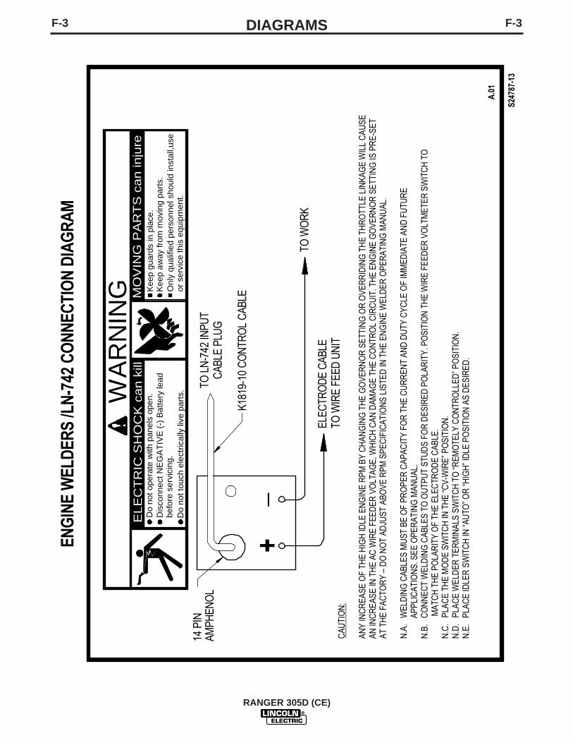
F-3DIAGRAMSF-3
RANGER 305D (CE)
or s
ervi
ce th
is e
quip
men
t.O
nly
qual
ified
per
sonn
el s
houl
d in
stal
l,use
Keep
aw
ay fr
om m
ovin
g pa
rts.
Kee
p gu
ards
in p
lace
.M
OV
ING
PA
RT
S c
an in
jure
WA
RN
ING
Do
not t
ouch
ele
ctric
ally
live
par
ts.
befo
re s
ervi
cing
.D
isco
nnec
t NE
GA
TIV
E (-
) Bat
tery
lead
Do
not o
pera
te w
ith p
anel
s op
en.
ELE
CT
RIC
SH
OC
K c
an k
ill
14 P
IN
AMPH
ENO
L
TO W
OR
K
+_
ENG
INE
WEL
DERS
/LN-
742
CONN
ECTI
ON
DIAG
RAM
S247
87-1
3
A.0
1
TO L
N-7
42 IN
PUT
CAB
LE P
LUG
ELEC
TRO
DE
CAB
LETO
WIR
E FE
ED U
NIT
CAU
TIO
N:
ANY
INC
REA
SE O
F TH
E H
IGH
IDLE
EN
GIN
E R
PM B
Y C
HAN
GIN
G T
HE
GO
VER
NO
R S
ETTI
NG
OR
OVE
RR
IDIN
G T
HE
THR
OTT
LE L
INKA
GE
WIL
L C
AUSE
AN IN
CR
EASE
IN T
HE
AC W
IRE
FEED
ER V
OLT
AGE,
WH
ICH
CAN
DAM
AGE
THE
CO
NTR
OL
CIR
CU
IT. T
HE
ENG
INE
GO
VER
NO
R S
ETTI
NG
IS P
RE-
SET
AT T
HE
FAC
TOR
Y –
DO
NO
T AD
JUST
ABO
VE R
PM S
PEC
IFIC
ATIO
NS
LIST
ED IN
TH
E EN
GIN
E W
ELD
ER O
PER
ATIN
G M
ANU
AL.
N.A
. W
ELD
ING
CAB
LES
MU
ST B
E O
F PR
OPE
R C
APAC
ITY
FOR
TH
E C
UR
REN
T AN
D D
UTY
CYC
LE O
F IM
MED
IATE
AN
D F
UTU
RE
A
PPLI
CAT
ION
S. S
EE O
PER
ATIN
G M
ANU
AL.
N.B
. C
ON
NEC
T W
ELD
ING
CAB
LES
TO O
UTP
UT
STU
DS
FOR
DES
IRED
PO
LAR
ITY.
PO
SITI
ON
TH
E W
IRE
FEED
ER V
OLT
MET
ER S
WIT
CH
TO
M
ATC
H T
HE
POLA
RIT
Y O
F TH
E EL
ECTR
OD
E C
ABLE
.N
.C.
PLA
CE
THE
MO
DE
SWIT
CH
IN T
HE
“CV-
WIR
E” P
OSI
TIO
N.
N.D
. P
LAC
E W
ELD
ER T
ERM
INAL
S SW
ITC
H T
O “R
EMO
TELY
CO
NTR
OLL
ED” P
OSI
TIO
N.
N.E
. P
LAC
E ID
LER
SW
ITC
H IN
“AU
TO” O
R “H
IGH
” ID
LE P
OSI
TIO
N A
S D
ESIR
ED.
K181
9-10
CO
NTR
OL
CAB
LE

F-4DIAGRAMSF-4
RANGER 305D (CE)
2
9/03
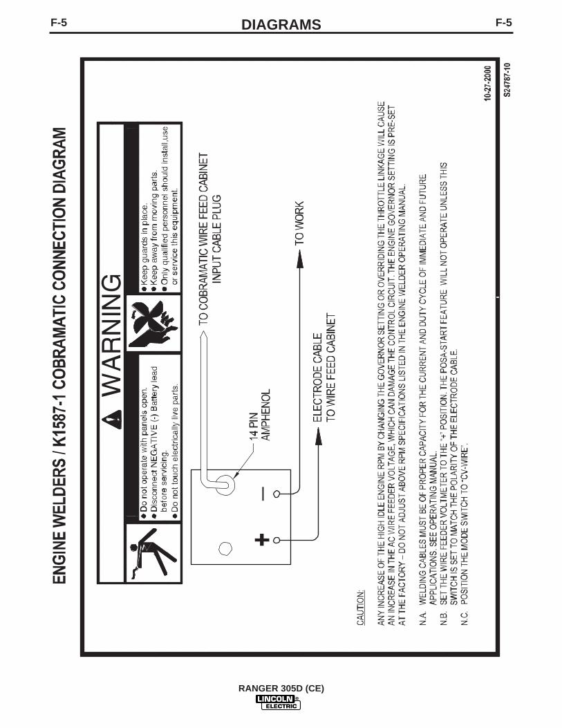
F-5DIAGRAMSF-5
RANGER 305D (CE)

F-6DIAGRAMSF-6
RANGER 305D (CE)
NO
TE
: T
his
dia
gra
m is
fo
r re
fere
nce
onl
y.
It m
ay n
ot
be
accu
rate
fo
r al
l mac
hine
s co
vere
d b
y th
is m
anua
l. T
he s
pec
ific
dia
gra
m f
or
a p
artic
ular
co
de
is p
aste
d in
sid
eth
e m
achi
ne o
n o
ne o
f th
e en
clo
sure
pan
els.
If
the
dia
gra
m is
ille
gib
le, w
rite
to
the
Ser
vice
Dep
artm
ent
for
a re
pla
cem
ent.
Giv
e th
e eq
uip
men
t co
de
num
ber
.

F-7DIAGRAMSF-7
RANGER 305D (CE)
NO
TE
: T
his
dia
gra
m is
fo
r re
fere
nce
onl
y.
It m
ay n
ot
be
accu
rate
fo
r al
l mac
hine
s co
vere
d b
y th
is m
anua
l. T
he s
pec
ific
dia
gra
m f
or
a p
artic
ular
co
de
is p
aste
d in
sid
eth
e m
achi
ne o
n o
ne o
f th
e en
clo
sure
pan
els.
If
the
dia
gra
m is
ille
gib
le, w
rite
to
the
Ser
vice
Dep
artm
ent
for
a re
pla
cem
ent.
Giv
e th
e eq
uip
men
t co
de
num
ber
.
CONT
ACTO
RCO
NTRO
L
SHOW
N IN
"WEL
DING
ON"
POSI
TION
WIR
E F
EED
PO
WE
R
W
IND
ING 42
VA
C
C11
C10
42 V
AC
STAT
OREX
CITA
TION
WIN
DING D3
AR
C C
ON
TRO
L
ALL
CAS
E F
RO
NT
CO
MP
ON
ENT
S S
HO
WN
VIE
WE
D F
RO
M R
EAR
.
42
W3
CB7
15A
S1
97W
1
STA
TOR
WEL
DW
IND
ING
S
W3
W2
75
R1
7677
278
CC
WOU
TPUT
CON
T. P
OT
S3
2
GN
D-E
300
AM
PM
OD
ULE
SHU
NT
50M
V=40
0 AM
PS
RO
TOR
STA
TOR
AU
X.W
IND
ING
CONN
ECTO
RS V
IEW
ED F
ROM
INSE
RTIO
N EN
DEL
ECTR
ICAL
SYM
BOLS
PER
E15
37
41
206B
206A
200A
201
201A20
0B
+
HO
UR
MET
ER22
4B
5
5H
HE
ATS
INK
208
4
279
BO
TTO
M G
ND
INSI
DE
LE
FTC
ASE
FRO
NT
PCB
1
D1
- TH
REE
PH
ASE
BRID
GE
REC
TIFI
ERW
4
W5
W6
W10
610
P4 -
J4
P5 -
J5
21
P6-J
6
16
8 1
9
P3-J
3
9
1
16
PCB
2 W
ELD
CO
NTR
OL
PC B
OA
RD
Met
er
Met
er
6
15
10
Shun
t
Sens
e/Id
ler/
PWM
204S
206S
2A
13
IDLE
SO
LEN
OID
5G
206S
204S
14
208B
8
CC
WR
2
B7 B8
L1 C
HOKE
W9 W8
WRA
P TW
O TU
RNS
OFLE
ADS
A, 3,
D, B
, & C
INDI
RECT
ION
SHOW
N TH
ROUG
H TO
ROID
RAN
GER
305
D C
E K
UB
OTA
WIR
ING
DIA
GR
AM -
UK
(FO
R C
OD
E 11
189)
IDLE
R CO
NTRO
L
SHOW
N IN
"AUT
O" P
OSIT
ION
S425
2
251
C3
800u
f15
0vdc
POSI
TIVE
BR
USH
CO
NNEC
TED
TO S
LIP
RIN
G N
EARE
STTO
THE
LAM
INAT
ION
W6
EN
GIN
E C
OM
PO
NE
NT
S
OIL
PRES
SW
W11
S1R
UN
-STO
PSW
ITC
H(S
HO
WN
INR
UN
PO
S.)
127
61
1 2
1 58
610
L2, L
3: R
F C
HO
KES
169
81
LEA
D C
OLO
R C
OD
E:B
=BLA
CK
OR
GR
AY
R=R
ED
OR
PIN
KW
=WH
ITE
G=G
RE
EN
(W/Y
ELLO
W S
TRIP
E)
FRAM
E GN
D.
45
1
41A
42A
15A
208A
21
S5
VO
LTM
ETE
RP
OLA
RIT
YSW
ITC
H
206A
SH
OW
N IN
PO
SIT
IVE
(+)
PO
SIT
ION
6
15
10
AMPS
M1M2M3
M1
M2
M3M4
M9
M5
M10
M10M9M6M5M4
M6
VOLT
S
M1M2M3
M10M9M6M5M4
15 15
M1
M2
M3M4
M9
M5
M10 M6
15 15
M1
M2
M3M4
M9
M5
M10
15 15
M1
M2
M3M4
M5
M10
11
M1
M2
M3M4
M5
M10
11
M1
M2
M3M4
M5
M10
15 15
M1
M2
M3M4
M9
M5
M10 M6
15 15
M1
M2
M3M4
M9
M5
M10 M6
15 15
M1
M2
M3M4
M9
M5
M10
15 15
M1
M2
M3M4
M9
M5
M10
15 15
M1
M2
M3M4
M9
M5
M10
15 15
M1
M2
M3M4
M9
M5
M10
G45
72-1
31 32 GN
D-B
A B C D E F
77B
21 75B
GN
D-A
41A
42A
76B
115V
AC
CO
NTA
CTO
R
77B
76B
WO
RK
75B
REM
OTE
CO
NTR
OL
42V
AC
GR
OU
ND
AM
PHE
NO
L 1
REM
OTE
CO
NTA
CTO
R
GR
OU
ND
AM
PHE
NO
L 2
CO
NTR
OL
J A D CH BK E F GI
208C
206C
BYPA
SSFI
LTE
RAS
SEM
BLY
5N
4B 2B 2B 4B
208C
206C
206B
4A
77A
76A
75A
2A 4A
Engi
ne P
rote
ctio
nLi
ght
PL1
212A
PULL
CO
IL B
D.
B4
PCB3
S7 GLO
WPL
UG
BUTT
ON
H2O
TEMP
SW
GLOW
PLUGS
9
1
16
8
7
1
12
6
P7 -
J7O
utpu
t &A
rc C
ont.
Mod
eSe
lect
P2 -
J2En
gine
&B
atte
ryFu
nctio
n
P1 -
J1A
mph
enol
,M
odel
Sele
ct,
Hot
Sta
rt
C8
C9
2523
Twis
ted
Pai
r
B4
B5
B6
B1
B2
B3
W5
B1B2
B3
8 514
12
34
P72
J72
210A
P43-
J43
200
777675
277
279
278
277
214
218
220
222
215
252
251
305
77A
76A
75A
2 4
208B
260
261
1314 23
260
261
215
232
212
209
229B
224B
5G
404
404
5K
5K
210H
200N
210B
GN
D-R
GN
D-K
GN
D-N
GN
D-E
GN
D-N
5K5N
GN
D-G GN
D-DG
ND
-C
GN
D-A
GN
D-R
GN
D-B
GN
D-J
200N
R3
25
Key
Key
ALTERNATOR
STAR
TER
FUEL
SO
LEN
OID
blk
wht
red
P73
J73
CO
ILP
ULL
CO
ILH
OLD
blk
wht
red
CO
ILP
ULL
CO
ILH
OLD
BAT
IGN
L
229
223
209A
209B
231
S2
STA
RT
BU
TTO
ND4
211
210
229A
229A
210D
210D
210E
223A
223A
210C
225B
224
210H
5H
210A
210B
GN
D-R
R4
301
302
GN
D-K
GN
D S
CR
EW O
NFA
N B
AFFL
E.
A
W7
W10
CB2
CB3
CB4
5F
CB1
20A
1A1B
1C
RC
DI
30m
A
79
11
5B
EL1
L1
L2
L2
12
L3
L3
2A
2A2C
2C2B
2B
NA E
D
15A
NA E
15A
AD
15A
5
E
D
C B
BC
A
C B
CB5
D
A
NO
TE: L
EADS
31
AND
32
NO
T US
ED.
TAPE
LEA
D E
NDS
AN
D S
ECUR
E.
NO
TE: S
TATO
R L
EAD
3 N
OT
USED
.TA
PE L
EAD
EN
D A
ND
SEC
URE.
E
5DJ1
00J1
01J1
02
230
FUEL
SE
ND
ER
5L
P52
230
210J
5L
41 J5
2
FUEL
GA
UG
E5M
5M
210J
TOP
GN
D. S
CR
EW O
NIN
SID
E LE
FT C
ASE
FRO
NT
GN
D. S
CR
EW
ON
RIG
HT
INSI
DE
CA
SEFR
ON
T
L6
L4
L3
L2
L5
L7 L8
5D
NL3L2
L1
(LO
CA
TED
BE
LOW
TE
RM
INAL
2)
1
218
220
CV
PIPE
CC TI
G22
2
A
S6
MO
DE
SEL
EC
TO
R S
WIT
CH
2 43
TWIS
TED
PAI
R
12 V
OLT
BATT
ERY
-+
GN
D-H
FRAM
EG
RO
UN
DG
ND
-J
ENG
INE
GR
OUN
DGN
D-L
224C
210F
210F
963
741
BA
CR
1
224A
224A
210G

F-8DIAGRAMSF-8
RANGER 305D (CE)
NO
TE
: T
his
dia
gra
m is
fo
r re
fere
nce
onl
y.
It m
ay n
ot
be
accu
rate
fo
r al
l mac
hine
s co
vere
d b
y th
is m
anua
l. T
he s
pec
ific
dia
gra
m f
or
a p
artic
ular
co
de
is p
aste
d in
sid
eth
e m
achi
ne o
n o
ne o
f th
e en
clo
sure
pan
els.
If
the
dia
gra
m is
ille
gib
le, w
rite
to
the
Ser
vice
Dep
artm
ent
for
a re
pla
cem
ent.
Giv
e th
e eq
uip
men
t co
de
num
ber
.
3
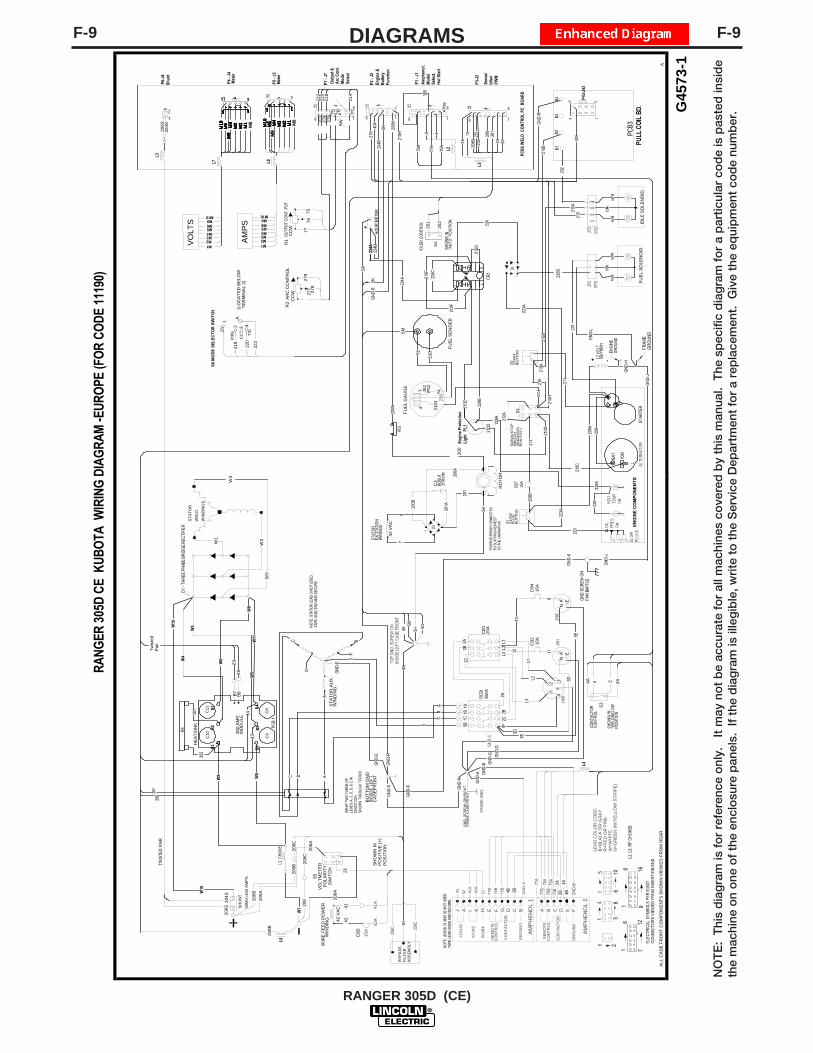
F-9DIAGRAMSF-9
RANGER 305D (CE)
NO
TE
: T
his
dia
gra
m is
fo
r re
fere
nce
onl
y.
It m
ay n
ot
be
accu
rate
fo
r al
l mac
hine
s co
vere
d b
y th
is m
anua
l. T
he s
pec
ific
dia
gra
m f
or
a p
artic
ular
co
de
is p
aste
d in
sid
eth
e m
achi
ne o
n o
ne o
f th
e en
clo
sure
pan
els.
If
the
dia
gra
m is
ille
gib
le, w
rite
to
the
Ser
vice
Dep
artm
ent
for
a re
pla
cem
ent.
Giv
e th
e eq
uip
men
t co
de
num
ber
.
CONT
ACTO
RCO
NTRO
L
SHOW
N IN
"WEL
DING
ON"
POSI
TION
WIR
E FE
ED P
OW
ER
W
IND
ING 42
VAC
C11
C10
42 V
AC
STAT
OREX
CITA
TION
WIN
DING D3
ARC
CO
NTR
OL
ALL
CAS
E FR
ON
T C
OM
PON
ENTS
SH
OW
N V
IEW
ED F
RO
M R
EAR
.
42
CB7
15A
S1
97W
1
STA
TOR
WEL
DW
IND
ING
S
W3
W2
75
R1
7677
278
CC
WOU
TPUT
CON
T. P
OT
S3
2
GN
D-E
300
AMP
MO
DU
LESH
UN
T50
MV=
400
AMPS
RO
TOR
STA
TOR
AU
X.W
IND
ING
CONN
ECTO
RS V
IEW
ED F
ROM
INSE
RTIO
N EN
DEL
ECTR
ICAL
SYM
BOLS
PER
E15
37
41
206B
206A
200A
201
201A20
0B
+
HO
UR
MET
ER22
4B
5
5H
HEA
TSIN
K
208
4
279
BOTT
OM
GN
DIN
SID
E LE
FTC
ASEF
RO
NT
PCB
1
D1
- TH
REE
PH
ASE
BRID
GE
REC
TIFI
ERW
4
W5
W6
W10
610
P4 -
J4
P5 -
J5
21
P6-J
6
16
8 1
9
P3-J
3
9
1
16
PCB
2 W
ELD
CO
NTR
OL
PC B
OA
RD
Met
er
Met
er
6
15
10
Shun
t
Sens
e/Id
ler/
PWM
204S
206S
2A
13
IDLE
SO
LEN
OID
5G
206S
204S
14
208B
8
CC
WR
2
B7 B8
L1 C
HOKE
W9 W8
WRA
P TW
O TU
RNS
OFLE
ADS
A, 3,
D, B
, & C
INDI
RECT
ION
SHOW
N TH
ROUG
H TO
ROID
RAN
GER
305
D C
E K
UBO
TA W
IRIN
G D
IAG
RAM
-EUR
OPE
(FO
R C
OD
E 11
190)
IDLE
R CO
NTRO
L
SHOW
N IN
"AUT
O" P
OSIT
ION
S425
2
251
C3
800u
f15
0vdc
POSI
TIVE
BR
USH
CO
NNEC
TED
TO S
LIP
RIN
G N
EARE
STTO
THE
LAM
INAT
ION
W6
EN
GIN
E C
OM
PO
NE
NT
S
OIL
PRES
SW
W11
S1R
UN
-STO
PSW
ITC
H(S
HO
WN
INR
UN
PO
S.)
127
61
1 2
1 58
610
L2, L
3: R
F C
HO
KES
169
81
LEAD
CO
LOR
CO
DE:
B=BL
ACK
OR
GR
AY
R=R
ED O
R P
INK
W=W
HIT
EG
=GR
EEN
(W/Y
ELL
OW
STR
IPE)
FRAM
E GN
D.
45
1
41A
42A
15A
208A
21
S5
VOLT
MET
ERPO
LAR
ITY
SWIT
CH
206A
SHO
WN
INPO
SIT
IVE
(+)
POS
ITIO
N
6
15
10
AMPS
M1M2M3
M1
M2
M3M4
M9
M5
M10
M10M9M6M5M4
M6
VOLT
S
M1M2M3
M10M9M6M5M4
15 15
M1
M2
M3M4
M9
M5
M10 M6
15 15
M1
M2
M3M4
M9
M5
M10
15 15
M1
M2
M3M4
M5
M10
11
M1
M2
M3M4
M5
M10
11
M1
M2
M3M4
M5
M10
15 15
M1
M2
M3M4
M9
M5
M10 M6
15 15
M1
M2
M3M4
M9
M5
M10 M6
15 15
M1
M2
M3M4
M9
M5
M10
15 15
M1
M2
M3M4
M9
M5
M10
15 15
M1
M2
M3M4
M9
M5
M10
15 15
M1
M2
M3M4
M9
M5
M10
G45
73-1
31 32 GN
D-B
A B C D E F
77B
21 75B
GN
D-A
41A
42A
76B
115V
AC
CO
NTA
CTO
R
77B
76B
WO
RK
75B
REM
OTE
CO
NTR
OL
42VA
C
GR
OU
ND
AM
PHE
NO
L 1
REM
OTE
CO
NTA
CTO
R
GR
OU
ND
AM
PHE
NO
L 2
CO
NTR
OL
J A D CH BK E F GI
208C
206C
BYPA
SSFI
LTER
ASSE
MBL
Y5N
4B 2B 2B 4B
208C
206C
206B
4A
77A
76A
75A
2A 4A
Engi
ne P
rote
ctio
nLi
ght
PL1
212A
PULL
CO
IL B
D.
B4
PCB3
S7 GLO
WPL
UG
BUTT
ON
H2O
TEMP
SW
GLOW
PLUGS
9
1
16
8
7
1
12
6
P7 -
J7O
utpu
t &A
rc C
ont.
Mod
eSe
lect
P2 -
J2En
gine
&B
atte
ryFu
nctio
n
P1 -
J1A
mph
enol
,M
odel
Sele
ct,
Hot
Sta
rt
C8
C9
2523
Twis
ted
Pai
r
B4
B5
B6
B1
B2
B3
W5
B1B2
B3
8 514
12
34
P72
J72
210A
P43-
J43
200
777675
277
279
278
277
214
218
220
222
215
252
251
305
77A
76A
75A
2 4
208B
260
261
1314 23
260
261
215
232
212
209
229B
224B
5G
404
404
5K
5K
210H
200N
210B
GN
D-R
GN
D-K
GN
D-N
GN
D-E
GN
D-N
5K5N
GN
D-G GN
D-DG
ND
-C
GN
D-A
GN
D-R
GN
D-B
GN
D-J
200N
R3
25
Key
Key
ALTERNATOR
STAR
TER
FUEL
SO
LEN
OID
blk
wht
red
P73
J73
CO
ILP
ULL
CO
ILH
OLD
blk
wht
red
CO
ILP
ULL
CO
ILH
OLD
BAT
IGN
L
229
223
209A
209B
231
S2
STA
RT
BU
TTO
ND4
211
210
229A
229A
210D
210D
210E
223A
223A
210C
225B
224
210H
224A
5H
210A
210B
GN
D-R
R4
301
302
GN
D-K
GN
D S
CR
EW O
NFA
N B
AFFL
E.
A
W7
W10
CB2
CB4
5F
CB1
20A
1A1B
1C
RC
DI
30m
A
811
5B
L1
L1
L2
L2
12
L3
L3
2A
2A2C
2C2B
2B
NA E
15A
NA E
15A
A
5
E
C B
BC
A
C B
CB5
D
A
NO
TE: L
EADS
31
AND
32
NO
T US
ED.
TAPE
LEA
D E
NDS
AN
D S
ECUR
E.
NO
TE: S
TATO
R L
EAD
3 N
OT
USED
.TA
PE L
EAD
EN
D A
ND
SEC
URE.
E
5DJ1
00J1
01J1
02
230
FUEL
SEN
DER
5L
P52
230
210J
5L
41 J5
2
FUEL
GAU
GE
5M5M
210J
TOP
GN
D. S
CR
EW O
NIN
SID
E LE
FT C
ASE
FRO
NT
GN
D. S
CR
EW
ON
RIG
HT
INSI
DE
CA
SEFR
ON
T
L6
L4
L3
L2
L5L7 L8
5D
NL3L2
L1
(LO
CA
TED
BEL
OW
TER
MIN
AL 2
)
1
218
220
CV
PIPE
CC TI
G22
2
A
S6
MO
DE
SEL
EC
TO
R S
WIT
CH
2 43
TWIS
TED
PAI
R
12 V
OLT
BATT
ERY
-+
GN
D-H
FRAM
EG
RO
UN
DG
ND
-J
ENG
INE
GR
OUN
DGN
D-L
5E
5E
10
W3
224C
210F
210F
963
741
BA
CR
1
224A
224A
210G

F-10DIMENSION PRINTF-10
RANGER 305D (CE)
MM20
335
A.
A.
02
60.2
115
29.3
29.6
775
3.6
26.5
267
3.6
60.0
015
24.0
59.2
015
03.7
17.5
044
4.5
19.5
049
5.3
21.0
653
4.9
21.5
054
6.1
29.8
375
7.6
34.2
486
9.8
35.7
790
8.4
6.33
160.
9
11.0
328
0.2
29.6
375
2.6
17.0
043
1.8
CEN
TER
OF
GRA
VITY

NOTES
RANGER 305D (CE)

NOTES
RANGER 305D (CE)

NOTES
RANGER 305D (CE)

WARNING
AVISO DEPRECAUCION
ATTENTION
WARNUNG
ATENÇÃO
Spanish
French
German
Portuguese
Japanese
Chinese
Korean
Arabic
READ AND UNDERSTAND THE MANUFACTURER’S INSTRUCTION FOR THIS EQUIPMENT AND THE CONSUMABLES TO BEUSED AND FOLLOW YOUR EMPLOYER’S SAFETY PRACTICES.
SE RECOMIENDA LEER Y ENTENDER LAS INSTRUCCIONES DEL FABRICANTE PARA EL USO DE ESTE EQUIPO Y LOSCONSUMIBLES QUE VA A UTILIZAR, SIGA LAS MEDIDAS DE SEGURIDAD DE SU SUPERVISOR.
LISEZ ET COMPRENEZ LES INSTRUCTIONS DU FABRICANT EN CE QUI REGARDE CET EQUIPMENT ET LES PRODUITS AETRE EMPLOYES ET SUIVEZ LES PROCEDURES DE SECURITE DE VOTRE EMPLOYEUR.
LESEN SIE UND BEFOLGEN SIE DIE BETRIEBSANLEITUNG DER ANLAGE UND DEN ELEKTRODENEINSATZ DES HER-STELLERS. DIE UNFALLVERHÜTUNGSVORSCHRIFTEN DES ARBEITGEBERS SIND EBENFALLS ZU BEACHTEN.
● Do not touch electrically live parts orelectrode with skin or wet clothing.
● Insulate yourself from work andground.
● No toque las partes o los electrodosbajo carga con la piel o ropa moja-da.
● Aislese del trabajo y de la tierra.
● Ne laissez ni la peau ni des vête-ments mouillés entrer en contactavec des pièces sous tension.
● Isolez-vous du travail et de la terre.
● Berühren Sie keine stromführendenTeile oder Elektroden mit IhremKörper oder feuchter Kleidung!
● Isolieren Sie sich von denElektroden und dem Erdboden!
● Não toque partes elétricas e elec-trodos com a pele ou roupa molha-da.
● Isole-se da peça e terra.
● Keep flammable materials away.
● Mantenga el material combustiblefuera del área de trabajo.
● Gardez à l’écart de tout matérielinflammable.
● Entfernen Sie brennbarres Material!
● Mantenha inflamáveis bem guarda-dos.
● Wear eye, ear and body protection.
● Protéjase los ojos, los oídos y elcuerpo.
● Protégez vos yeux, vos oreilles etvotre corps.
● Tragen Sie Augen-, Ohren- und Kör-perschutz!
● Use proteção para a vista, ouvido ecorpo.

WARNING
AVISO DEPRECAUCION
ATTENTION
WARNUNG
ATENÇÃO
Spanish
French
German
Portuguese
Japanese
Chinese
Korean
Arabic
LEIA E COMPREENDA AS INSTRUÇÕES DO FABRICANTE PARA ESTE EQUIPAMENTO E AS PARTES DE USO, E SIGA ASPRÁTICAS DE SEGURANÇA DO EMPREGADOR.
● Keep your head out of fumes.● Use ventilation or exhaust to
remove fumes from breathing zone.
● Los humos fuera de la zona de res-piración.
● Mantenga la cabeza fuera de loshumos. Utilice ventilación oaspiración para gases.
● Gardez la tête à l’écart des fumées.● Utilisez un ventilateur ou un aspira-
teur pour ôter les fumées des zonesde travail.
● Vermeiden Sie das Einatmen vonSchweibrauch!
● Sorgen Sie für gute Be- undEntlüftung des Arbeitsplatzes!
● Mantenha seu rosto da fumaça.● Use ventilação e exhaustão para
remover fumo da zona respiratória.
● Turn power off before servicing.
● Desconectar el cable de ali-mentación de poder de la máquinaantes de iniciar cualquier servicio.
● Débranchez le courant avant l’entre-tien.
● Strom vor Wartungsarbeitenabschalten! (Netzstrom völlig öff-nen; Maschine anhalten!)
● Não opere com as tampas removidas.● Desligue a corrente antes de fazer
serviço.● Não toque as partes elétricas nuas.
● Do not operate with panel open orguards off.
● No operar con panel abierto oguardas quitadas.
● N’opérez pas avec les panneauxouverts ou avec les dispositifs deprotection enlevés.
● Anlage nie ohne Schutzgehäuseoder Innenschutzverkleidung inBetrieb setzen!
● Mantenha-se afastado das partesmoventes.
● Não opere com os paineis abertosou guardas removidas.

• Sales and Service through Subsidiaries and Distributors Worldwide •
Cleveland, Ohio 44117-1199 U.S.A. TEL: 216.481.8100 FAX: 216.486.1751 WEB SITE: www.lincolnelectric.com
• World's Leader in Welding and Cutting Products •