eMVP/MVP - HYFAB · - 1 - IOM Manual . eMVP/MVP . Installation, Operation & Maintenance Manual....
68
IOM Manual eMVP/MVP Installation, Operation & Maintenance Manual Modular Variable Speed Pressure Boosters with M172 v5.xx Software Document: 687-468
Transcript of eMVP/MVP - HYFAB · - 1 - IOM Manual . eMVP/MVP . Installation, Operation & Maintenance Manual....

- 1 -
IOM Manual
eMVP/MVP Installation, Operation & Maintenance Manual
Modular Variable Speed Pressure Boosters
with M172 v5.xx Software
Document: 687-468

2
IOM Manual
Table of Contents
Contents................................................................................................................................................................ 5 Description and Specifications ............................................................................................................................. 5 Nameplate ............................................................................................................................................................. 5 Engineering Data.................................................................................................................................................. 5 HFP Pumps Safety Instructions ........................................................................................................................... 6 User Safety…………………………………………………………………………………………………….………7
Personal Safety ................................................................................................................................................... 7 Safety Equipment ............................................................................................................................................... 7 Workplace Safety ............................................................................................................................................... 7 Washing the skin and eyes .................................................................................................................................. 7
Start-Up ................................................................................................................................................................ 8 System Components ............................................................................................................................................. 9 Storage ................................................................................................................................................................ 10
Delivery Inspection .......................................................................................................................................... 10 Package Inspection ........................................................................................................................................... 10 Unit Inspection ................................................................................................................................................. 10 Safety ............................................................................................................................................................... 10 Location and Treatment .................................................................................................................................... 10 Indoor Storage .................................................................................................................................................. 10 Outdoor Storage ............................................................................................................................................... 10 Installed But Not in Service .............................................................................................................................. 11 Equipment Protection ....................................................................................................................................... 11 Preparation for Operation ................................................................................................................................. 11
Installation Guide ............................................................................................................................................... 12 Installation Checklist ......................................................................................................................................... 14 3.5” Color Touchscreen ...................................................................................................................................... 15 Controller Menu Structure ................................................................................................................................ 16 Display Settings Menu Map ............................................................................................................................... 17 Booster Controller Features ............................................................................................................................... 18 Booster Controller Sequence of Control ............................................................................................................ 19 Color Touchscreen Instructions ......................................................................................................................... 20 Booster Interior Controller ................................................................................................................................ 24 Booster Controller Navigation ........................................................................................................................... 25
Main Menu ...................................................................................................................................................... 25 Status ............................................................................................................................................................... 25 Alarms ............................................................................................................................................................. 26 Configuration ................................................................................................................................................... 26 Pump Enable .................................................................................................................................................... 27

3
IOM Manual
Operating Mode ............................................................................................................................................... 28
No Flow Standby.............................................................................................................................................. 28 Alarms/Shutdown ............................................................................................................................................. 29 Contact Inputs .................................................................................................................................................. 30 DemandSet ....................................................................................................................................................... 31 Pump Run Timers ............................................................................................................................................ 31 Pressure Sensors ............................................................................................................................................... 32 Factory Settings................................................................................................................................................ 34 PID Tuning ...................................................................................................................................................... 36 Pump Staging ................................................................................................................................................... 39 Display Settings ............................................................................................................................................... 39 System ............................................................................................................................................................. 39 Offline ............................................................................................................................................................. 40 Diagnostics ...................................................................................................................................................... 40
Building Automation System Integration .......................................................................................................... 41 Port Locations .................................................................................................................................................... 41 BAS Configuration Menu Structure .................................................................................................................. 43
BAS Config ..................................................................................................................................................... 43 Modbus TCP .................................................................................................................................................... 43 BACnet IP........................................................................................................................................................ 44 BACnet MSTP ................................................................................................................................................. 44 Modbus RTU ................................................................................................................................................... 44 Lon Protocol .................................................................................................................................................... 44 Ethernet Configuration ..................................................................................................................................... 44 RS-485 Configuration....................................................................................................................................... 45
Schneider Electric Altivar 212 ........................................................................................................................... 47 Modified Parameter List ................................................................................................................................... 47
Allen Bradley PowerFlex 523 ............................................................................................................................. 48 Modified Parameter List ................................................................................................................................... 48
Schneider Magellis STU 655/855 ........................................................................................................................ 49 Regular Cleaning................................................................................................................................................ 49
Cleaning the Display ........................................................................................................................................ 49 Cleaning the Gasket.......................................................................................................................................... 49 Inserting the Gasket .......................................................................................................................................... 49 Periodic Check Points ....................................................................................................................................... 49
Installation.......................................................................................................................................................... 50 Location ........................................................................................................................................................... 50 Close-Coupled Units ........................................................................................................................................ 50
Piping.................................................................................................................................................................. 50 Piping Suction .................................................................................................................................................. 50

4
IOM Manual
Wiring & Grounding.......................................................................................................................................... 50 Rotation .............................................................................................................................................................. 51 Operation ........................................................................................................................................................... 51 Maintenance ....................................................................................................................................................... 51
Seasonal Service............................................................................................................................................... 52 Monthly Maintenance ....................................................................................................................................... 52
Troubleshooting Guide....................................................................................................................................... 53 Replacement Parts ............................................................................................................................................. 55
MVP Drawing .................................................................................................................................................. 55 Typical Goulds 3656-S Pump End................................................................................................................ 56
Typical Cla-Val Angle Check Valve ............................................................................................................ 56
Standard MVP Parts Table ........................................................................................................................... 57
7-Series MVP Parts Table ............................................................................................................................ 58
eMVP Drawing, 5SV-22SV .............................................................................................................................. 59 Goulds e-SV Pump End, 5SV-22SV ............................................................................................................. 60
EMVP Parts Table, 5SV-22SV ..................................................................................................................... 60
eMVP Drawing, 33SV-92SV ............................................................................................................................ 62 Goulds e-SV Pump End, 33SV-92SV ........................................................................................................... 63
EMVP Parts Table, 33SV-92SV ................................................................................................................... 64
Optional Booster Accessories ........................................................................................................................... 65 Frequently Asked Questions .............................................................................................................................. 66 Additional Components ..................................................................................................................................... 67
Baldor Motors ....................................................................................................................................................... 67 Cla-Val Check Valve ........................................................................................................................................ 67 Goulds Model 3656, e-SV Pumps ..................................................................................................................... 67
Magelis HMI .................................................................................................................................................... 67
Modicon M172 ................................................................................................................................................. 67
Square D Altivar VFD ...................................................................................................................................... 67
Allen Bradley PowerFlex 523 VFD .................................................................................................................. 67
Therm-Omega Tech Econo/HAT-RA ............................................................................................................... 67
Warranty ............................................................................................................................................................ 68

5
IOM Manual
Contents eMVP™/MVP™ Pressure Booster Systems are shipped with:
• eMVP™/MVP™ Installation Guide • Startup Checklist • Controller Instructions • Schneider Altivar 212 / Allen Bradley PowerFlex 523 Modified Parameter Tables • Typical 208 and 460 VAC Wiring Diagrams
These materials are sufficient for most startups. For more complete information on particular components, the following
reference documents (as well as the ones shipped with the unit) are available at http://www.hyfabco.com/index.cfm?sp=boosters. If unable to view or print these documents, printed copies may be requested from the submittal department of the James M. Pleasants Company by calling 800-365-9010. Please specify requested document numbers when calling. Description and Specifications The MVP pumps are modified Goulds 3656 series single stage, end-suction, centrifugal pumps. The eMVP pumps are modified Goulds eSV series multistage pumps. Pump impellers are fully enclosed, key driven and held in position by an impeller bolt and washer. Casings are full volute in design with replaceable wear rings. Depending on the pump size, the pump suction and discharge connections will be threaded or flanged. Shafts are protected with stainless steel shaft sleeves. Close-coupled units have NEMA Premium Efficient JM or JP motors with C-face mounting and key driven shaft extension.
Nameplate Located on every pump station is a nameplate that details information about the pump station. The nameplate is located on the side of the controller cabinet. When contacting the manufacturer, please detail:
• Model Size • Serial Number • Item numbers for applicable parts
Engineering Data Maximum Liquid Temperature:
250º F (120º C) – Standard Viton Seal Maximum Working Pressure (Fluid Temperature Dependent):
– NPT connections, 200 PSI (1379 kPa) – 125# ANSI flanged connections, 200 PSI (1379 kPa)
Maximum Suction Pressure: 100 PSI (689.5 kPa) Starts per Hour: 20, evenly distributed Pump Suction: 2” (Standard MVP), 3" NPT (MVP, 7-Series), 1.25” to 4”, 125#, 250# Flange (eMVP) Pump Discharge: 1.5” NPT (Standard MVP), 2.5” NPT (MVP, 7-Series), 1.25” to 4”, 125#, 250# Flange (eMVP)

6
IOM Manual
Pump Safety Instructions
Important: Read all safety information prior to installation of the eMVP/MVP.
TO AVOID SERIOUS OR FATAL PERSONAL INJURY OR MAJOR PROPERTY DAMAGE, READ AND FOLLOW ALL SAFETY INSTRUCTIONS IN
THE MANUAL AND ON THE PUMP. This is a SAFETY ALERT SYMBOL. When you see this symbol on the pump or in the manual, look for one of the following signal words and be alert to the potential for personal injury or property damage. Warns of hazards that WILL cause serious personal injury, death or major property damage.
Warns of hazards that CAN cause serious personal injury, death or major property damage. Warns of hazards that CAN cause personal injury or property damage.
NOTICE: INDICATES SPECIAL INSTRUCTIONS WHICH ARE VERY IMPORTANT AND MUST BE
FOLLOWED. THIS MANUAL IS INTENDED TO ASSIST IN THE
INSTALLATION AND OPERATION OF THIS UNIT. THOROUGHLY REVIEW ALL INSTRUCTIONS
AND WARNINGS PRIOR TO PERFORMING ANY WORK ON THIS PUMP.
MAINTAIN ALL SAFETY DECALS.
NOTICE: INSPECT UNIT FOR DAMAGE AND
REPORT ALL DAMAGE TO CARRIER IMMEDIATELY.
UNIT NOT DESIGNED FOR USE WITH HAZARDOUS LIQUIDS OR
FLAMMABLE GASES.
NOTICE: All operating instructions must be read, understood and followed
by the operating personnel. HYFAB accepts no liability for damages or
operating disorders which are the result of non-compliance with the operating
instructions.

7
IOM Manual
User Safety Personal Safety In any situation:
• Keep the work area clean and free from any potential hazards. • Be mindful of the potential risks for injuries related to burns, electric shocks, toxic fluids, and hazardous
pressure. • Be mindful of hazardous voltage and avoid all electrical hazards. • Be mindful of the risks associated with gas and vapors in the workplace.
Safety Equipment Personal safety equipment must be worn and used to all applicable standards/regulations. The following safety equipment is recommended in the workplace:
• Fully stocked first-aid kits • Protective goggles with side shields attached • Hearing protection • Sturdy protective gloves • Sturdy steel-toed shoes • Sturdy hard hat • Safety devices • Gas masks
Workplace Safety When working on the eMVP/MVP, or nearby, be mindful of the following safety precautions:
• Always work with others nearby. Do not work alone. • Be mindful of and stay away from suspended loads. • If the eMVP/MVP is in automatic operation, be mindful of the potential risk of a sudden start. • Use an appropriate lifting device when positioning the MVP/eMVP. • Wear appropriate protective clothing. • If pump disassembly is required, clean and sufficiently rinse the components with potable water prior to
reassembly. • Do not operate equipment unless all safety guards are in place • While the system is pressurized and/or energized, do not open any vents or drains or remove any plugs.
System must be isolated electrically and mechanically with all pressure relieved prior to any disassembly. Isolate the pump from the system and relieve the pressure before disassembling the pump, removing plugs, or disconnecting piping.
• Care should be taken to ensure that equipment is NOT operated at pressures above the pump or other system components’ listed maximum operating pressure.
Washing the skin and eyes If chemicals or hazardous fluids come into contact with the skin or eyes: Chemicals/Hazardous fluids on skin
• Take off contaminated clothing. • Wash skin with soap and water for at least one minute. • If necessary, seek medical attention. •
Chemicals/Hazardous fluids in eyes • Hold eyelids open with fingers. • Rinse eyes with eyewash or running water for at least fifteen minutes. • Seek medical attention.

8
IOM Manual
Start-Up 1. This manual is intended to assist in the installation, operation and maintenance of the system and must be kept with the system or at a readily accessible location. 2. Installation and maintenance MUST be performed by properly trained and qualified personnel. 3. Review all instructions and warnings prior to performing any work on the system.
4. The system MUST be disconnected from the main power supply before attempting any operation or maintenance on the electrical or mechanical part of the system. Failure to disconnect electrical power before attempting any operation or maintenance can result in electrical shock, burns or death.
5. Anytime power is applied to unit, the motor and pump could start unexpectedly and cause serious injury.
6. Do not operate at pressure(s) above fixture/component pressure ratings.
7. Always follow local, state or provincial codes for plumbing and electrical safety.
Hazardous
Voltage
Hazardous
Energy
Hazardous Pressure

9
IOM Manual
System Components Review the eMVP/MVP components and ensure that all parts are present and that the installer is familiar with their names. Inspect all components for shipping damage. eMVP: � Goulds eSV Series Multistage Pump (Including Dry Run Sensor [Optional]) � Suction Header (Including Electronic Suction Pressure Transmitter & Gauge) � Discharge Header (Including Electronic Discharge Pressure Transmitter & Gauge) � Frame � Check Valve (Including Electronic Temperature Probe) � 460V/208V Control Panel � 460V/208V Variable Frequency Drives MVP: � Goulds 3656 series single stage pump � Suction Header (Including Electronic Suction Pressure Transmitter & Gauge) � Discharge Header (Including Electronic Discharge Pressure Transmitter & Gauge) � Frame � Check Valve (Including Electronic Temperature Probe) � 460V/208V Control Panel � 460V/208V Variable Frequency Drives
Any exposed metal in the system piping, including transducer case, must be grounded to the service
entrance per NFPA 70: National Electrical Code, Article 250.
DO NOT power the unit or run the pump until all electrical and plumbing connections, especially the pressure transmitter connection, are completed. Do not run the pump dry. All electrical work must be
performed by a qualified technician. Always follow the National Electrical Code (NEC), or the Canadian Electrical Code (CEC) as well as all local, state and provincial codes. Code questions should
be directed to the local electrical inspector. Failure to follow electrical codes and OSHA safety guidelines may result in personal injury or equipment damage. Failure to follow manufacturer's
installation instructions may result in electrical shock, fire hazard, personal injury, death, damage to equipment, unsatisfactory performance and may void the manufacturer's warranty.

10
IOM Manual
Storage Delivery Inspection
Package Inspection • Ensure that there are no missing or damaged items at delivery. • If missing or damaged items are discovered, note on the receipt and freight bill. • If there is a problem, file a claim with the shipping company.
Unit Inspection
• Remove and dispose of all packing materials in accordance with local regulations. • Inspect for any missing or damaged parts. • Unfasten the eMVP/MVP from its restraints by removing any screws, bolts, or straps present. Be careful
when handling nails or straps. • If anything is out of order, contact your sales representative.
NOTICE: Instructions and information supplied with the eMVP/MVP are only relevant to the eMVP/MVP. Equipment and other accessories not part of the eMVP/MVP that are offered separately by other manufacturers must
be handled according to those manufacturer’s recommendations and instructions for storage and usage. For the purposes of this manual, storage lasting thirty days or more is considered long term.
Safety • Store in a hazard-free location that poses no potential dangers to workers or others that may enter the area. • Handle safely upon arrival and during subsequent transportation. • Store the MVP/eMVP on a level and stable surface that can bear the equipment weight. Do not stack or
store in a manner that could lead to the equipment tipping or falling. Location and Treatment Indoor Storage
• Store in an environment with stable temperatures between 35°F and 104°F. • Keep out of direct sunlight. • Protect from dirt and dust. • Ensure that there is no moisture build-up:
o Properly ventilate o Tightly seal with desiccant
• In humid or dusty conditions, care for the eMVP/MVP as if it were stored outdoors. • If storing in a condensing environment, coat steel or cast-iron surfaces with rust-inhibiting oil. • Isolate stored equipment from other equipment and minimize exposure to vibration. • All equipment piping openings should be covered during storage.
Outdoor Storage
• Protect from the elements and direct sunlight by securely covering. • Ensure that coverings are safely secured from potential high winds. • Cover securely such that moisture is unable to build up underneath the cover.
o Properly ventilate o Tightly seal with desiccant
• All water should be drained from equipment prior to outdoor storage to prevent damage to equipment. • Inspect the storage area weekly. • Inspect the storage area after strong weather, inspecting covers for any damage. • Inspect suction and discharge manifold flange covers.

11
IOM Manual
Installed, But Not in Service
• Tightly close suction and discharge valves. • Remove water from all pumps and piping. Completely dry the interior of all pumps and piping. • Examine external steel or cast-iron surfaces for moisture build-up every thirty days and maintain corrosion
inhibitors during inspection. Equipment Protection
• Pumps o Rotate the pump and motor shaft by hand at least ten times every thirty days to prevent the
potential for binding and bearing damage. Rest the shaft in different positions. o If tools are required to rotate pump and motor, do so carefully to ensure that shaft is not damaged. o If the coupling guard is removed during hand-rotation of the pump or motor shafts, make sure that
it is reinstalled before removing any safety tagging, lockouts, or starting the equipment. • Control Panel, VFDs, and other electronics
o If any electronic materials are stored for more than ninety days, insert moisture absorbing packets within the enclosed space. Replace the packets when necessary. Remove packets before starting up any equipment.
• Package Enclosures o Seal any housing vents and/or openings with plastic wrap and waterproof tape. o Protect against condensation.
Preparation for Operation
• Remove rust inhibitors from all machine surfaces. • Remove all corrosion protective materials. • Remove flange covers, tape, and any unnecessary piping plugs.

12
IOM Manual
eMVP/MVP Installation Guide Purpose This manual is provided to present some of the standard ways to install, operate and maintain this equipment. Read this manual before start-up, or performing maintenance on the unit. Also, refer to this guide for basic troubleshooting procedures and factory support information. Operating Conditions Standard units are designed for indoor installation in spaces with temperatures between 35°F and 104°F and humidity levels below 95%, non-condensing. Installation in conditions outside this range may result in unsatisfactory equipment performance and loss of warranty coverage. Location Unit installation location should allow for ease of inspection, maintenance and service to all equipment components. Leveling Unit must be leveled and anchored to structure, A base 2.5 times the weight of the booster unit is recommended. Consult submittal data for unit weight. In noise-sensitive areas, consult a sound specialist for the base and anchor design.
WARNING: UNIT PIPING CONNECTIONS SHOULD BE COMPLETED BY A COMPETENT AND LICENSED PLUMBER IN COMPLIANCE WITH LOCAL CODES. FAILURE TO FOLLOW THESE
INSTRUCTIONS COULD RESULT IN SERIOUS PERSONAL INJURY, DEATH AND/OR PROPERTY DAMAGE.
Piping Inlet and outlet connection may be made on either end of the inlet and discharge header. Standard connections are 4” grooved and require grooved couplings not supplied by HYFAB. Other sizes and connectors such as copper adapters, flange adapters and flexible connectors are available from HYFAB as options. Piping must be supported such that the weight of connected piping is not transferred to the booster package.
• Connect inlet piping. Consult grooved coupling instructions for connection details. If an inlet reduction is required, an eccentric reducer must be installed flat on top to prevent air trapping.
• Connect discharge piping. Consult grooved coupling instructions for connection details. If an outlet
reduction is required, an eccentric reducer must be installed flat on top to prevent air trapping.
• Thermal relief valve discharge piping (1/2” O.D. copper) should be routed to a safe location. This piping may discharge hot water in event of a temperature build-up.
Lubrication All pumps and motors should be lubricated before running equipment.

13
IOM Manual
Wiring WARNING: UNIT ELECTRICAL CONNECTIONS MUST BE COMPLETED BY A COMPETENT AND
LICENSED ELECTRICIAN IN COMPLIANCE WITH NEC AND LOCAL CODE REQUIREMENTS. FAILURE TO FOLLOW THESE INSTRUCTIONS COULD RESULT IN SERIOUS PERSONAL INJURY,
DEATH AND/OR PROPERTY DAMAGE. Verify that supply voltage and ampacity available are consistent with package requirements. Connect power and ground unit per wiring diagram supplied with unit.

14
IOM Manual
eMVP/MVP Installation Checklist
Y N N/A
1 _____ _____ _____ Standard units are designed for indoor installation in spaces with temperatures between 35°F and 104°F and humidity levels below 95%, non-condensing. Installation in conditions outside this range may result in unsatisfactory operation and loss of warranty coverage.
2 _____ _____ _____ Unit location should provide reasonable access for inspection, maintenance and service of all components.
3 _____ _____ _____ Unit must be leveled and anchored to structure. A base 2.5 times the weight of the booster unit is recommended. Consult submittal for unit weight. In noise sensitive areas, consult a sound specialist for the base and anchor design.
4 _____ _____ _____ WARNING: UNIT PIPING CONNECTIONS SHOULD BE COMPLETED BY A
COMPETENT AND LICENSED PLUMBER IN COMPLIANCE WITH LOCAL CODES. FAILURE TO FOLLOW THESE INSTRUCTIONS COULD RESULT IN SERIOUS
PERSONAL INJURY, DEATH AND/OR PROPERTY DAMAGE.
5 _____ _____ _____
Inlet and outlet connection can be made on either end of the inlet and discharge header. Standard connections are 4” grooved and require grooved couplings not supplied by HYFAB. Other sizes and connectors such as copper adapters, flange adapters and flexible connectors are available from HYFAB as options. Piping must be supported such that the weight of connected piping is not transferred to the booster unit.
6 _____ _____ _____ Connect inlet piping. Consult grooved coupling instructions for connection details. If an inlet reduction is required, an eccentric reducer must be installed flat on top to prevent air trapping.
7 _____ _____ _____ Connect discharge piping. Consult grooved coupling instructions for connection details. If an outlet reduction is required, an eccentric reducer must be installed flat on top to prevent air trapping.
8 _____ _____ _____ Route thermal relief valve discharge piping (1/2” O.D. copper) to a safe location. This piping may discharge hot water in event of a temperature build-up.
9 _____ _____ _____ If used, pressurize the hydropneumatic tank with air to 90% of desired operating setpoint. Consult hydropneumatic installation instructions for details. HYFAB offers a discharge header cap option for a tank connection which includes a combination shutoff/drain valve. Do not open the shutoff valve to admit water into the tank before it is pressurized with air.
10 _____ _____ _____
WARNING: UNIT ELECTRICAL CONNECTIONS MUST BE COMPLETED BY A COMPETENT AND LICENSED ELECTRICIAN IN COMPLIANCE WITH NEC AND LOCAL CODE REQUIREMENTS. FAILURE TO FOLLOW THESE INSTRUCTIONS COULD RESULT IN SERIOUS PERSONAL INJURY, DEATH AND/OR PROPERTY
DAMAGE.
11 _____ _____ _____ Verify that available supply voltage and ampacity are consistent with package requirements.
12 _____ _____ _____ Connect power and ground unit per wiring diagram supplied with unit.
Sign when completed Name Date

15
IOM Manual
3.5” Color Touchscreen

16
IOM Manual
Controller Menu Structure

17
IOM Manual
Display Settings Menu Structure
Diagnostics...System...Offline...
Main Menu
Diagnostics...System...Offline...
Main Menu
MultiMedia...Web Gate...IO Manager...Option...Self Test...Backlight…Buzzer...Network...
Offline
MultiMedia...Web Gate...IO Manager...Option...Self Test...Backlight…Buzzer...Network...
Offline
Option...Brightness...Memory...Ver. Info...Language...Restart...Date/Time...Stylus...
System
Option...Brightness...Memory...Ver. Info...Language...Restart...Date/Time...Stylus...
System
Statistics...Variables...
Diagnostics
Statistics...Variables...
Diagnostics
Defualt Gateway?Subnet Mask?IP Address?Static IP
Defualt Gateway?Subnet Mask?IP Address?Static IP
NetworkNetwork
Host Name?Enable DHCP?DHCP
Host Name?Enable DHCP?DHCP
IP Address?Obtain DNS Setting?MAC Address Info:MAC/DNS
IP Address?Obtain DNS Setting?MAC Address Info:MAC/DNS
None?Buzzer
None?Buzzer
When Press / TouchObject?When Press / TouchObject?
Sec / Minutes?Wait?
Backlight
Sec / Minutes?Wait?
Backlight
Enable Touch ifBacklight is Out?Enable Touch ifBacklight is Out?
Self TestSelf Test
NOR Check?Int’l ASCII?Simp. Chinese?Trad. Chinese?Korean?Japanese?Char. Pattern
NOR Check?Int’l ASCII?Simp. Chinese?Trad. Chinese?Korean?Japanese?Char. Pattern
Disp. PatternDisp. PatternTouch PanelTouch PanelCOM 1COM 1COM 2COM 2Video MemoryVideo Memory
Enable Oper Switch?COM1 Pwr Sup NoneCOM1 Pwr Sup On
Option
Enable Oper Switch?COM1 Pwr Sup NoneCOM1 Pwr Sup On
Option
Tx Wait TimeRcv. Time Out?Retry Count?Data Length?Stop Bit?Parity Bit?Transmission Speed?Serial Hdwr Protocol?Select Driver?Driver Config
Tx Wait TimeRcv. Time Out?Retry Count?Data Length?Stop Bit?Parity Bit?Transmission Speed?Serial Hdwr Protocol?Select Driver?Driver Config
IO ManagerIO Manager
ASCII Byte Order?Double Word Order?Pref Frame Length?Slave Equip Address?Select Equipment?Equipment Config
ASCII Byte Order?Double Word Order?Pref Frame Length?Slave Equip Address?Select Equipment?Equipment Config
Not SupportedNot Supported
Not SupportedNot Supported
StylusStylus
Date / TimeDate / Time
Seconds?Minutes?Hour?Day?Month?Year?Date / Time
Seconds?Minutes?Hour?Day?Month?Year?Date / Time
Adj for Daylight Sav?Zone?Time Zone
Adj for Daylight Sav?Zone?Time Zone
Subtract Time?Add Time?Amount?Type?DST
Subtract Time?Add Time?Amount?Type?DST
RestartRestart
Keyboard Language?User Application?System?
Language
Keyboard Language?User Application?System?
Language
Build Number:Vijeo Designer Ver:Vijeo Runtime Ver:
Version
Build Number:Vijeo Designer Ver:Vijeo Runtime Ver:
Version
Main:Secondary:DRAM:Used:Total:
Memory
Main:Secondary:DRAM:Used:Total:
Memory
Contrast?Brightness?
Brightness
Contrast?Brightness?
Brightness
Not SupportedNot Supported
Equipment?VariablesEquipment?Variables
Inv. Request:Unsupp. Req.:Xmit Fail:Intrn Error:Write Fail:Init. Fail:Inv. Resp.:Error Resp.Wrong Address:Chksum Fail:No Reply:Total Count:Total Bad:Total Good:Equipment?Variables
Inv. Request:Unsupp. Req.:Xmit Fail:Intrn Error:Write Fail:Init. Fail:Inv. Resp.:Error Resp.Wrong Address:Chksum Fail:No Reply:Total Count:Total Bad:Total Good:Equipment?Variables
StatisticsStatistics

18
IOM Manual
Standard Variable Speed Control Panel Features
• U/L 508A Listed Industrial Control Panel • Digital programmable logic pump controller
(PLC) with door mounted 3.5” Touchscreen Interface with all parameters displayed in English
• Internally protected DC power supply for controls
• Flo-Check no demand shut down control logic
• Digital input for remote enable/disable • Full color back-lit touchscreen with all
parameters and pumping terminology in English
• Temperature sensor for each pump • Door operated main power disconnect • Automatic lead/lag pump alternation (equal
size pumps required) • Variable frequency drive (VFD) for each
pump (mounted externally) • Digital output for general alarm monitoring • Motor circuit protector for each pump/VFD • NEMA 1 enclosure • Pump protection logic • Single point power connection
Standard Alarms
• Pump/VFD fault • Low system pressure • High and low suction pressure
shutdown/alarm
• High and low discharge pressure shutdown/alarm
• High temperature shutdown/alarm • Low water level shutdown/alarm (opt.
sensor required) Screen Indication Features
• Power on • Pump out of service • General Fault • Pump/VFD Status • System pressure
• Suction pressure • Discharge temperature • Pump elapsed run time • Pump failure detection
Optional Features
• Audio Alarm with silencing button • Low water level shutdown sensor • NEMA 4 enclosure • 5.7” full color touchscreen • BACnet MS/TP communication
• BACnet /IP communication • Modbus RTU / TCP communication • LonWorks communication • DemandSet Control

19
IOM Manual
Sequence of Control Pump(s) Start The pump runs when the system pressure is less than the start pressure setpoint (adjustable % of setpoint) and no standby conditions exist. After the pump starts, it runs until a No Flow Standby (NFSB) condition is initiated. Staging Control The lead pump speed varies to maintain the system pressure setpoint via Proportionate Integral Derivative (PID) control of drive speed. If pressure cannot be maintained by the lead pump, the lag pump is started. De-staging Control When system demand can be met by a single pump and the lag pump minimum run timer is satisfied, the lag pump is stopped. No Flow Standby (NFSB) When the pump logic controller senses a no-flow condition for 120 seconds (adjustable) it will initiate a flow-check test. If the test confirms a no-flow condition, the lead pump will shut down and remain off until a start condition exists. High Temperature Shutdown (HTSD) The pump(s) will shut down if their respective discharge temperature exceeds 120°F (adjustable) for 60 seconds (adjustable). Reset will occur when the temperature falls 10°F (adjustable) below the shutdown setpoint. HTSD will occur regardless of the minimum run timer condition. A HTSD will activate the remote alarm relay. Setting the HTSD setpoint to zero will eliminate all references to pump temperature, including the display of temperature and HTSD alarming. A HTSD alarm condition activates the remote alarm contact. Low Suction Pressure Shutdown (LSSD) When suction pressure falls below the LSSD setpoint 10 psi (adjustable) for 15 seconds (adjustable) the pump(s) will shutdown. Reset will occur and pump(s) will restart when the pressure exceeds the LSSD setpoint by 5 PSI (adjustable). This function is independent of the minimum run timer condition. Setting the suction pressure transmitter span to 0 will disable this function and remove all references to suction pressure from the booster system control sequence. A LSSD will activate the remote alarm delay. This alarm will reset automatically when suction pressure rises above the LSSD setpoint for the selected timer duration. A LSSD alarm condition activates the remote alarm contact. High Suction Pressure Shutdown (HSSD) If the suction pressure remains above the HSSD setpoint 0 psi (adjustable) for 60 seconds (adjustable) the booster system will be shutdown and a HSSD alarm will be generated. Once the suction pressure falls below the HSSD setpoint, the HSSD alarm will be cleared and the booster system will be permitted to restart. A HSSD setpoint of 0 (default) locks out the HSSD feature. A HSSD alarm condition activates the remote alarm contact.

20
IOM Manual
High Discharge Pressure Shutdown (HPSD) If the discharge pressure remains above the HPSD setpoint 110 psi (adjustable) for 60 seconds (adjustable) the booster system will be shutdown and a HPSD alarm will be generated. The booster system will remain locked out until the HPSD alarm is manually reset via the booster operator interface. A HPSD alarm condition activates the remote alarm contact. Low Supply Pressure Shutdown (LSPS) If the discharge pressure remains below the LSPS setpoint 0 psi (adjustable) for 30 seconds (adjustable), a LSPS alarm will be generated. If the LSPS alarm is activated and the LSPS system lockout is enabled, the booster system will be shutdown. If a LSPS shutdown is activated, booster system will remain locked out until the LSPS alarm is manually reset via the booster operator interface. A LSPS setpoint of 0 (default) locks out the LSPS feature. A LSPS alarm condition activates the remote alarm contact. Pump Failure Alarm (VFD/PUMP) If a pump is commanded to start and fails to start within the pump alarm delay 10 sec (adjustable) time window as sensed by its VFD run contact, a pump alarm will be generated. If the lead pump fails to start, a lag pump will be started. A pump failure alarm condition activates the remote alarm contact. If a pump is NOT commanded to start and is sensed running for the VFD operation alarm delay 30 seconds (adjustable), a VFD in manual alarm will be generated. The VFD in manual alarm condition activates the remote alarm contact. DemandSet Control (Optional) For DemandSet to be operational, flow indication via hardwired flow meter, or calculated flow must be present. Once flow indication has been established, DemandSet can be configured. Demand set requires two user configured values: (1) Maximum system flow (2) variable system head via building height, or variable head loss. Once DeamandSet has been configured, the system pressure setpoint will be reset based on booster system demand. Booster will continuously monitor system flow and decrease the system pressure setpoint based on the calculated variable head loss between booster discharge and critical fixture. Color Touchscreen Instructions These instructions refer to the operation of the booster controller from the color touchscreen operator interface located on the outside front of the control cabinet.

21
IOM Manual
A system status display band runs along the bottom of the screen. Various messages are displayed along this band including:
• Normal System Operation • *** Remote Enable Off *** • *** ALERT ***, Timed Rotation Now In Progress. • *** ALERT ***, Bladder Tank Charging. • Current System Alarm
Current System Alarm Current System Alarm is the only alert which requires attention. A blinking red message indicates that an alarm condition exists. If an alarm condition exists:
• The blinking Current System Alarm message functions as a menu button. • Touch the alarm message to go directly to the alarm summary screen. All active system alarms are
displayed here. • Once the current alarms have been evaluated, press Esc to return to the alarm menu. • From the alarm menu:
o Alarms may be reset o The Alarm History can be accessed.
Default Screen After 5 minutes of inactivity, the touchscreen will display a default screen containing a pressure meter with the system setpoint in the center and a range of -10 PSI to +10 PSI. Touch the default screen to return to the system status screen series.

22
IOM Manual
System Status Screen
Esc Button On the right side of the System Status screens are buttons used for navigating the graphic menu system. In the upper right corner is the Esc button. The Esc button opens the Main Menu or previously displayed screen. Gph Button Directly below the Esc button is the Gph button. Pressing the Gph button displays the default pressure meter screen. It is only visible on the System Status screens. Ver Button Directly below the Gph button is the Ver button. Pressing the Ver button displays the current versions of the Touchscreen, Controller, Firmware and Time/Date settings. It is only visible on System Status screen. M+/M- Buttons M+ Button In the lower right corner of the display is the M+ button. When visible, The M+ button indicates that another screen is available. Pressing the M+ button advances the display to the next screen. M- Button When visible, the M- button indicates the ability to return to the previous screen. Pressing the M- button returns the display to the previously viewed screen. On the first System Status screen, touching the following headings will display their associated graph:
• Discharge Pressure • Suction Pressure (if used) • Discharge Temperature or Remote Pressure (if used) • System Flow (if available)
The time range of the graph is displayed on the bottom line. Touching the time range toggles it between 2, 10 and 30 minutes. System Variables Most system variables for the application are set prior to the unit’s shipment. Typically, the only variables that need to be adjusted are the setpoint and possibly the loop tuning parameters.

23
IOM Manual
Setpoint NOTICE: The system Setpoint is only available via the System Status screens.
1. If the default screen is displayed, touch the display to clear the default screen and display the System Status screen.
2. Once the System Status screen is displayed, press the M+ button once to display the Sys Setpoint: ###psi screen.
3. Touch the number ### to adjust the setpoint. 4. A numeric entry keypad will open on the display. Using the keypad, type in the new setpoint and press the
enter button in the lower right corner. 5. After adjusting the setpoint and pressing the enter button, the user will be returned to the previous display
and the new setpoint will be displayed. 6. The system start pressure will change accordingly.
• Adjusting the restart % changes the system start pressure. • Press the M+ or M- keys to navigate through the status screen series. • If additional parameters in the attached table must be changed, press the Esc button. • The Esc button will display the controller’s Main Menu where additional adjustments can be made. • The Main Menu matrix illustrates the menu system of the touchscreen. All system adjustments can be made
from this menu. Password Most of the Configuration menu items require a password to change.
• When prompted for a password, the user name is 1 and the password is 1. • Once the user name and password are entered, press the unlock button in the lower right corner of the
password screen. • Press the return button in the lower center of the password screen to return to the Configuration screens.
NOTICE: After 10 minutes of inactivity, the operator credentials time out and must be re-entered to make changes to the controller’s configuration. Menu Navigation Using the Esc, M+, and M- buttons, the entire touchscreen menu system can be navigated. Booster Starting & Running The booster starts when the system pressure is less than the system start pressure and no shutdown conditions exist. After the booster starts, it runs for a minimum of 5 minutes. The pump will run longer if water usage is occurring in the system. Once water usage has stopped, the unit will run until the No Flow Stand By (NFSB) condition is achieved. As soon as water usage begins, the system will restart automatically.

24
IOM Manual
Booster Interior Controller
NOTICE: These instructions are pertinent to the most recent model of the controller, Schneider Electric M172 Controller and Magelis STU HMI 655. Previous models include the Carel PCO XS Controller and the Schneider Electric M168 controllers displayed above. There may be discrepancies between the displays of the
most recent model and older versions. Utilize these instructions accordingly. For information on the installation and operation of the Carel PCO XS Controller, or the Schneider M168 Controller, please contact
HYFAB.
Schneider M172 Controller The date and time must be set via the color operator interface on the front of the control panel. To set the date and time, navigate to the Display Settings menu via the System Config menu. The Date/Time are set via the display’s System menu. The controller periodically polls the display and synchronizes its time to the display time. During power outages, the controller maintains the correct time and date via an onboard real-time clock with battery backup. During powerup. The display’s clock is updated with the correct time from the controller’s real-time clock.
NOTICE: To ensure accurate event time recordings, set the date and time on the controller as soon as possible after installation.

25
IOM Manual
Booster Controller Navigation
System Status Menu Item Variable Default Range Field
Value Discharge Pr: • Displays current system Discharge Pressure
• Touching text activates the graph function 0 to 999
Suction Pr: • Displays current system Suction Pressure, if configured
• Touching text activates the graph function
0 to 999
Discharge Temp:/ Remote Pr:
• Displays highest temperature reading of installed temperature sensors, or remote system pressure, if used
Meas/Calc Flow: • Total flow • Will read ‘Meas Flow’ if hardwired flow
meter used • Will read ‘Calc Flow’ if sensorless flow is
being used
0 to 9999
Sys Setpoint: • System Discharge Pressure Setpoint 50 0 to 999 Restart %: • Minimum percentage of system pressure
setpoint required for system restart 90 0 to 99
System Start: • Displays Calculated System Start Pressure • Based on System Setpoint and Restart %
0 to 999
Stage: Pumps: • Displays the number of stages called for and the number of pumps running
Pump 1: • Displays pump status and % of full speed Pump 2: • Visible only in Dplx, Tplx, or Qplx modes
• Displays pump status and % of full speed
Pump 3: • Visible only in Tplx or Qplx modes • Displays pump status and % of full speed
Pump 4: • Visible only in Qplx mode • Displays pump status and % of full speed
P1 Hours: • Total pump run hours P2 Hours: • Visible only in Dplx, Tplx, or Qplx modes
• Total pump run hours
P3 Hours: • Visible ony in Tplx or Qplx modes • Total pump run hours
Main Menu Menu Item Variable Default Range Field
Value Status: • Opens the System Status screen series
Alarms: • Opens the Alarm menu • Displays current Alarms Summary and
Alarm History • Resets current alarms
Configuration: • Opens the system Configuration menu • Password required to access all system
parameters
Reserved: • This item is reserved for use at a later date

26
IOM Manual
Alarms Menu Item Variable Default Range Field
Value Alarm Summary: • Opens the Alarm Summary screen
• Contains a summary of all active alarms
Alarm History: • Opens the Alarm History screen • Contains the last 100 alarm events
Alarm Reset: • Resets current alarms • Press and hold one second then release
Configuration Menu Item Variable Default Range Field
Value Pump Enable: • Opens the Pump Enable/Stg configuration
screen • Enables or disables individual pumps • Sets the fixed rotation sequence number of
the pumps, if fixed rotation has been selected
Operating Mode: • Opens the Booster Config screen series • Selects the number of booster pumps (1-4)
by setting to Splx, Dplx, Tplx, or Qplx • Defines the standby and rotation sequences
No Flow Standby: (NFSB)
• Opens the NFSB Config screen series • NFSB Puts the booster in standby mode
when there is no system demand
Alarms/Shutdown: • Opens the Alarms/System Shutdown screens • Configures HTSD, LSSD, HSSD, HPSD,
LSPS, VFD/PUMP shutdown/alarms
Contact Inputs: • Opens the Contact Inputs screen • Enables and configures LLCO and RSS
inputs
DemandSet: (Only visible if system
flow available)
• Opens the DemandSet Configuration screen • Adjusts the booster supply setpoint based on
measured or calculated flow
System Status Continued Menu Item Variable Default Range Field
Value P4 Hours: • Visible only in Qplx mode
• Total pump run hours
P1 Temperature: • Pump discharge temperature P2 Temperature: • Visible only in Dplx, Tplx, or Qplx modes
• Pump discharge temperature
P3 Temperature: • Visible only in Tplx or Qplx modes • Pump discharge temperature
P4 Temperature: • Visible only in Qplx mode • Pump discharge temperature

27
IOM Manual
Pump Enable Menu Item Variable Default Range Field
Value Pump 1: Stg: • Enabled / Disabled – Stg # Ena - 1 Ena/Dis – 1-4 Pump 2: Stg: • Visible only in Dplx, Tplx, or Qplx modes
• Enabled / Disabled – Stg # Ena - 2 Ena/Dis – 1-4
Pump 3: Stg: • Visible only in Tplx or Qplx modes • Enabled / Disabled – Stg #
Ena - 3 Ena/Dis – 1-4
Pump 4: Stg: • Visible only in Qplx mode • Enabled / Disabled – Stg #
Ena - 4 Ena/Dis – 1-4
Configuration Continued Menu Item Variable Default Range Field
Value Pump Run Timers: • Opens the Pump Run Timers screen
• Sets the minimum on, minimum off and crossover times
• Resets the pump run hours
Pressure/Flow Sensors: • Opens the Sensor Config screen series • Configures the Discharge Pressure, Suction
Pressure, Flow Meter, & Remote Pressure sensors
Factory Settings: • Opens the Factory Config screen series • Sets the temperature sensor calibration and
units • Selects flow devices & factory parameters
PID Tuning: • Opens the PID Tuning screen • Sets the pump speed response to system
pressure
Pump Staging: • Opens the Pump Staging screen series • Sets the system parameters that control when
the system starts and stops additional pumps NOTICE: These parameters can be viewed, but
require a high-level password to modify.
Display Settings: • TIME AND DATE are SET HERE • Opens the Controller Display screens • Offline/System/Diagnostics menus
Modbus Diagnostics • Provides communication diagnostics for the VFD communication bus
• The VFD communication bus is only used when sensorless flow data is required
BAS Setup (Only visible if BMS
communication module installed)
• Opens BAS setup screens. The BAS Setup menu option will only be available if BAS connectivity was purchased. If BAS connectivity is required and this menu option is not visible, contact your booster provider. BAS modules can be purchased and added to the controller in the field. For more details see the BAS Setup section.

28
IOM Manual
(NFSB) No Flow Standby
Menu Item Variable Default Range Field Value
NFSB Enable? (NFSB Menu 1)
• Enables or Disables No Flow Standby • None of the following No Flow Standby
variables are visible if NFSB is disabled
Yes Yes/No
Sample Time? (NFSB Menu 1)
• The amount of time in seconds the drive speed will be steady prior to the unit entering a NFSB sequence
120 1 to 999
Test Duration? (NFSB Menu 1)
• The amount of time in seconds the controller tests the NFSB sequence variables for verification
5 2 to 30
Drive DB? (NFSB Menu 2)
• Dead Band speed range the drive must operate within to initiate a No Flow Shutdown Test
0.5 00.0 to 99.9
Pressure DB? (NFSB Menu 2)
• Dead Band pressure range the system must operate within during No Flow Shutdown test to enter No Flow Shutdown Mode
3 1 to 20
Test Speed Reduction? (NFSB Menu 2)
• Amount the pump speed is reduced during the No Flow Shutdown test
5.0 -99.9 to 99.9
Bladder Tank Charge Time?
(NFSB Menu 3)
• The amount of time that the booster runs (in seconds) with the HyperCharge setpoint prior to shutting down under No Flow StandBy
10 0 to 999
Bladder Tank HyperCharge?
(NFSB Menu 3)
• The pressure setpoint adder that the booster operates at prior to shutting down under No Flow StandBy
0 0 to 20
Operating Mode Menu Item Variable Default Range Field
Value Booster Mode: • The mode for the package:
o Splx=1 pump (Simplex) o Dplx=2 pumps (Duplex) o Tplx=3 pumps (Triplex) o Qplx=4 pumps (Quadplex)
Splx Splx to Qplx
Standby Pump(s): • Not visible/applicable in Simplex mode • Assigns standby pump(s) in multiple pump
systems
0 0 – No. of System Pumps
Even Rotation: • Not visible/applicable in Simplex mode • Enables the rotation of pump(s) based on run
hours • Enabled prior to shipping
No No/Yes
Rotate Time: • Not visible/applicable if Even Rotation set to No.
• Details the amount of time in hours the system will run before a pump rotation can be made automatically
60 1 to 999
Current Lead: • Indicates which pump is currently selected for the lead by the controller
• Changes with each unit cycle, if rotation is enabled above
1 to 4

29
IOM Manual
Alarms/Shutdown
Menu Item Variable Default Range Field Value
Setpoint? (HTSD)
• High Temperature Shutdown Temperature • The maximum discharge temperature that the
system may reach prior to shutdown • System will start again once this value falls
below the HTSD setting by the amount of the High Temp Shutdown Reset Delta
120° F 0 to 200° F
Reset Delta? (HTSD)
• High temperature reset delta • The amount of discharge temperature
decrease the controller must realize prior to restarting the unit
10° F 5 to 100° F
Shutdown Del? (HTSD)
• Number of seconds the high temperature setpoint must be realized before the unit shuts down
15 2 to 30
Reset Temp: (HTSD)
• Calculated temperature the system will reach prior to restart
LSSD Setpoint? (LSSD)
• Low Suction Shutdown Pressure limit • Suction pressure below this setting will cause
the unit to shut down
10 -15 to 999
Shutdown Del? (LSSD)
• The time in seconds that low suction pressure is allowed before alarm occurs
15 0 to 60
Reset DB? (LSSD)
• The Low Suction Pressure Reset Pressure differential in PSI
• LSSD setpoint must be exceeded by this amount for the unit to restart
5 1 to 99
Reset Pressure: (LSSD)
• The calculated suction pressure required for system to restart
HSSD Setpoint? (HSSD)
• High Suction Shutdown Setpoint • Suction pressure above this setting will cause
to unit to shut down. • A HSSD setpoint of zero disables this feature
0 0 to 999
Shutdown Del? (HSSD)
• The time in seconds that high suction pressure is allowed before alarm occurs
60 0 to 999
HPSD Setpoint? (HPSD)
• High System Shutdown Pressure • Sets the maximum discharge pressure the
system may reach prior to shutdown • System requires a manual reset for this
condition
110 0 to 999
Shutdown Del? (HPSD)
• Time delay in seconds that the high system shutdown pressure is realized and sustained until the system shuts down
60 0 to 999

30
IOM Manual
Contact Inputs
Menu Item Variable Default Range Field Value
LLCO Enable? • Enables the Low Level Cutout function if enabled.
• Utilized for low water cutoff when pumping water from a vessel
No No/Yes
LLCO Contact? • Low Level Cutout Operation N.O. N.O./N.C. RSS Enable? • Enables Remote Start/Stop Function if
enabled No No/Yes
RSS Contact? • Remote Enable Operation N.O. N.O./N.C.
Alarms/Shutdown Continued Menu Item Variable Default Range Field
Value LSPS Setpoint?
(LSPS) • Low Supply Pressure Shutdown • Sets the minimum discharge pressure the
system may discharge prior to triggering an alarm event
• A LSPS setpoint of zero disables this feature
0 0 to 999
Delay? (LSPS)
• The time in seconds that low supply pressure is allowed before alarm occurs
30 0 to 999
Sys Lockout? (LSPS)
• If Enabled, this will stop the booster on a LSPS event and prevent the booster from restarting until the LSPS alarm is manually reset
Disabled Disabled /
Enabled
VFD Operation Alm Delay?
(VFD/PUMP)
• Time in seconds that a VFD can run while not commanded to before a VFD in Manual Operation Alarm is generated
30 0 to 999
Pump Alm Del? (VFD/PUMP)
• Time in seconds that a VFD can be commanded to operate and not return an ON status before a Pump Failure Alarm is generated
5 0 to 999

31
IOM Manual
Pump Run Timers
Menu Item Variable Default Range Field Value
Minimum On? • Establishes pump minimum on time in seconds
5 0 to 999
Minimum Off? • Establishes pump minimum off time in seconds
5 0 to 999
Crossover Time? • Establishes the length of time in seconds that a pump selected to shut down stays on line so other pump(s) can stabilize
• For example, during lead swap
10 0 to 999
Reset Pump Run Hours • Resets pump hours to zero
DemandSet (Only visible if system flow available) Menu Item Variable Default Range Field
Value User SP:
(Pressure & Flow) • The User Setpoint • Here for reference purposes only • The user setpoint can be adjusted via the
Status menu
0 to 999
DemandSet SP: (Pressure & Flow)
• The DemandSet Setpoint • Displays the working setpoint of the booster • The DemandSet setpoint is calculated using
Max Sys Flow and Variable Head Cfg • When actual system flow is at or above Max
Sys Flow, the DemandSet SP will equal the User SP
• As actual system flow falls below Max Sys Flow, the system variable head is used to calculate a lower DemandSet SP
0 to 999
Max Sys Flow? (Pressure & Flow)
• The highest anticipated flow the system is expected to deliver (usually design flow)
0 0 to 9999
Height? (Variable Head)
• Height of building in feet, or longest pipe run 0 0 to 9999
Variable Head Loss? (Variable Head)
• Actual System Variable Head Loss • If this variable is set to a value other than
zero, it will be used to calculate the DemandSet SP regardless of the Height setting
0 0 to 999

32
IOM Manual
Pressure/Flow Sensors Menu Item Variable Default Range Field
Value Zero?
(Discharge Pressure) • System Pressure Sensor Zero • Sets the minimum pressure of the discharge
pressure transducer in PSIG
0
-30 to 30
Span? (Discharge Pressure)
• System Pressure Sensor Span • The span of the discharge pressure
transducer in PSIG
300 0 to 999
Current: (Discharge Pressure)
• Displays the current discharge pressure reading
Failure Speed? (Discharge Pressure)
• Speed the system will operate the pumps in the event of a discharge pressure transducer failure
50 20 to 100
Zero? (Suction Pressure)
• Suction Pressure Sensor Zero • Sets the minimum pressure of the suction
pressure transducer in PSIG
0 -30 to 30
Span? (Suction Pressure)
• Suction Pressure Sensor Span • The span of the suction pressure transducer
in PSIG • Setting span to zero removes suction
pressure from alarm routines and display
300
0 to 999
Current: (Suction Pressure)
• Displays the current suction pressure reading
Flow Sensor? (Flow Meter)
• Enables booster flow feature • Selection of Meter enables hardwired meter
interaction with booster system • Once the Meter selection has been made the
4-20mA input hardware alarm is enabled for the flow meter input
• If Meter has been selected, Absence of flowmeter will cause a hardware failure alarm.
• Selection of Sensorless enables sensorless flow calculation interaction with booster system – This option only available on standard MVP boosters and typically enabled during factory setup
• Selection of Meter will override sensorless calculations
No No / Meter / Sensorless
Flow Zero? (Flow Meter)
• Hardwired flow meter zero 0 0 to 999
Flow Span? (Flow Meter)
• Hardwired flow meter span 0 0 to 9999
Flow: (Flow Meter)
• Displays the current hardwired flow meter reading

33
IOM Manual
Pressure/Flow Sensors Continued Menu Item Variable Default Range Field
Value Zero?
(Remote Pressure) • Remote pressure transmitter zero 0 -30 to 30
Span? (Remote Pressure)
• Remote pressure transmitter span • Setting span to anything other than zero
enables the remote pressure transmitter feature
• Once the remote pressure transmitter feature has been enabled, the 4-20mA input hardware alarm is enabled for the remote pressure transmitter input
• Absence of a remote pressure transmitter will cause a hardware failure alarm and automatically return the booster system to local header pressure control
• When the remote pressure feature is active, the HPSD and LSPS alarms continue to monitor the booster’s local header pressure
0 0 to 999
Offset +/-? (Remote Pressure)
• Added to, or subtracted from, final remote pressure reading
0 -99 to 99
Current: (Remote Pressure)
• Displays the current remote pressure reading
Alarm Type (Remote Pressure)
(Rem Hi Alm)
• Sets remote pressure high alarm type • Only available if remote pressure sensor has
been configured • Not Used – Remote pressure high alarm not
functional • Static SP – Results in a fixed high pressure
alarm setpoint • Offset SP – Results in a dynamic high
pressure alarm setpoint that is the result of adding the offset setpoint to the working setpoint
Not Used
Not Used / Static SP / Offset SP
Setpoint/Offset? (Remote Pressure)
(Rem Hi Alm)
• Value to be used as either the Static SP, or the Offset SP to be added to the working setpoint
0 0 to 999
Current SP: (Remote Pressure)
(Rem Hi Alm)
• Displays the current high pressure alarm setpoint
Delay? (Remote Pressure)
(Rem Hi Alm)
• Time delay in seconds that the high remote system pressure is realized and sustained until the high alarm is generated
0 0 to 999

34
IOM Manual
Factory Config
Menu Item Variable Default Range Field Value
Use Celsius Temps/Use Farenheit Temps
(General Cfg)
• Selects whether the temperatures are displayed as Fahrenheit, or Celsius
F
F/C
Flow Sensor? (General Cfg)
• Enables the flow sensor functions of Meter, Sensorless, or No
No No/Meter/ Sensorless
P1 VFD? (VFD/MFG)
• Available only if sensorless flow has been selected
• Sets model of VFD for Modbus communications
Altivar 212
Altivar 212 / AB PF 523 /
ABB ACH550 / Danfs FC102 / Future VFD3 / Future VFD4 / Future VFD5 / Future VFD6 / Future VFD7 / Future VFD8 /
P2 VFD? (VFD/MFG)
• Available only if sensorless flow has been selected
• Sets model of VFD for Modbus communications
• Visible only in Dplx, Tplx, or Qplx modes
Altivar 212
Altivar 212 / AB PF 523 /
ABB ACH550 / Danfs FC102 / Future VFD3 / Future VFD4 / Future VFD5 / Future VFD6 / Future VFD7 / Future VFD8 /
Pressure/Flow Sensors Continued Menu Item Variable Default Range Field
Value Alarm Type
(Remote Pressure) (Rem Low Alm)
• Sets remote pressure low alarm type • Only available if remote pressure sensor has
been configured • Not Used – Remote pressure low alarm not
functional • Static SP – Results in a fixed low pressure
alarm setpoint • Offset SP – Results in a dynamic low
pressure alarm setpoint that is the result of subtracting the offset setpoint from the working setpoint
Not Used
Not Used / Static SP / Offset SP
Setpoint/Offset? (Remote Pressure) (Rem Low Alm)
• Value to be used as either the Static SP, or the Offset SP to be subtracted from the working setpoint
0 0 to 999
Current SP: (Remote Pressure) (Rem Low Alm)
• Displays the current low pressure alarm setpoint
Delay? (Remote Pressure) (Rem Low Alm)
• Time delay in seconds that the low remote system pressure is realized and sustained until the low alarm is generated
0 0 to 999

35
IOM Manual
Factory Config Continued Menu Item Variable Default Range Field
Value P3 VFD?
(VFD/MFG) • Available only if sensorless flow has been
selected • Sets model of VFD for Modbus
communications • Visible only in Tplx, or Qplx modes
Altivar 212
Altivar 212 / AB PF 523 /
ABB ACH550 / Danfs FC102 / Future VFD3 / Future VFD4 / Future VFD5 / Future VFD6 / Future VFD7 / Future VFD8 /
P4 VFD? (VFD/MFG)
• Available only if sensorless flow has been selected
• Sets model of VFD for Modbus communications
• Visible only in Qplx mode
Altivar 212
Altivar 212 / AB PF 523 /
ABB ACH550 / Danfs FC102 / Future VFD3 / Future VFD4 / Future VFD5 / Future VFD6 / Future VFD7 / Future VFD8 /
RPM (VFD/MFG)
(DTA) Drive 1 Data…
• Displays current RPM of pump 1 read from VFD via Modbus communications
• Available only if sensorless flow has been selected
KW (VFD/MFG)
(DTA) Drive 1 Data…
• Displays current kW of pump 1 read from VFD via Modbus communications
• Available only if sensorless flow has been selected
Delay KW (VFD/MFG)
(DTA) Drive 1 Data…
• Displays average rolling average of the last 10 readings of kW of pump 1 read from VFD via Modbus communications
• Available only if sensorless flow has been selected
RPM (VFD/MFG)
(DTA) Drive 2 Data…
• Displays current RPM of pump 2 read from VFD via Modbus communications
• Available only if sensorless flow has been selected
• Visible only in Dplx, Tplx, or Qplx modes
KW (VFD/MFG)
(DTA) Drive 2 Data…
• Displays current kW of pump 2 read from VFD via Modbus communications
• Available only if sensorless flow has been selected
• Visible only in Dplx, Tplx, or Qplx modes
Delay KW (VFD/MFG)
(DTA) Drive 2 Data…
• Displays average rolling average of the last 10 readings of kW of pump 2 read from VFD via Modbus communications
• Available only if sensorless flow has been selected
• Visible only in Dplx, Tplx, or Qplx modes

36
IOM Manual
Factory Config Continued Menu Item Variable Default Range Field
Value RPM
(VFD/MFG) (DTA)
Drive 3 Data…
• Displays current RPM of pump 3 read from VFD via Modbus communications
• Available only if sensorless flow has been selected
• Visible only in Tplx, or Qplx modes
KW (VFD/MFG)
(DTA) Drive 3 Data…
• Displays current kW of pump 3 read from VFD via Modbus communications
• Available only if sensorless flow has been selected
• Visible only in Tplx, or Qplx modes
Delay KW (VFD/MFG)
(DTA) Drive 3 Data…
• Displays average rolling average of the last 10 readings of kW of pump 3 read from VFD via Modbus communications
• Available only if sensorless flow has been selected
• Visible only in Tplx, or Qplx modes
RPM (VFD/MFG)
(DTA) Drive 4 Data…
• Displays current RPM of pump 4 read from VFD via Modbus communications
• Available only if sensorless flow has been selected
• Visible only in Qplx mode
KW (VFD/MFG)
(DTA) Drive 4 Data…
• Displays current kW of pump 4 read from VFD via Modbus communications
• Available only if sensorless flow has been selected
• Visible only in Qplx mode
Delay KW (VFD/MFG)
(DTA) Drive 4 Data…
• Displays average rolling average of the last 10 readings of kW of pump 4 read from VFD via Modbus communications
• Available only if sensorless flow has been selected
• Visible only in Qplx mode

37
IOM Manual
Factory Config Continued Menu Item Variable Default Range Field
Value P1 Adj?
(Cal Temp Sens) • Used to calibrate Pump 1 Temperature • Calibrated temperature displayed to right of
calibration value
0 -99.9 to 99.9
P2 Adj? (Cal Temp Sens)
• Used to calibrate Pump 2 Temperature • Calibrated temperature displayed to right of
calibration value • Visible only in Dplx, Tplx, or Qplx modes
0 -99.9 to 99.9
P3 Adj? (Cal Temp Sens)
• Used to calibrate Pump 3 Temperature • Calibrated temperature displayed to right of
calibration value • Visible only in Tplx, or Qplx modes
0 -99.9 to 99.9
P4 Adj? (Cal Temp Sens)
• Used to calibrate Pump 4 Temperature • Calibrated temperature displayed to right of
calibration value • Visible only in Qplx mode
0 -99.9 to 99.9
Flow Zero? (Meter Cfg)
• Hardwired flow meter zero • Not visible if Flow Sensor is set to No
0 0 to 999
Flow Span? (Meter Cfg)
• Hardwired flow meter span • Not visible if Flow Sensor is set to No
0 0 to 9999
Flow Offset? (Meter Cfg)
• Sets Flow Sensor offset for calibration purposes
• Not visible if Flow Sensor is set to No
0 -999 to 999
Flow: (Meter Cfg)
• Displays Current Calculated Flow
Curve Data (Sensorless Cfg)
• Selects pump performance data by MVP model for sensorless flow calculation
MVP 630 208
MVP-630-208 / MVP-630-460 / MVP-850-208 / MVP-850-460 / MVP-875-208 / MVP-875-460 / MVP-8100-208 / MVP-8100-460 / MVP-8150-208 / MVP-8150-460 /
Custom 1 / Custom 2 / Custom 3 / Custom 4 / Custom 5 /
Sensorless Flow (Sensorless Cfg)
• Displays current sensorless flow calculation

38
IOM Manual
PID Tuning Menu Item Variable Default Range Field
Value Loop Ctl: • Sets type of control
• P = Proportional only • PI = Proportional with Integral • PID = Proportional with Integral and
Derivative • DC = Demand Control – This option is NOT
applicable to booster systems and should NOT be selected
PI
P, PI, PID, DC
Proportional: • Controls the initial reaction of the PID loop • The larger the number the greater the initial
response. • Visible only on P, PI, PID menus.
00.85 00.00 to 30.00
Integral: • Controls the amount that is continuously added or subtracted to the output based on the process variable in relation to the setpoint
• Trims the initial control response up, or down.
• The larger the number the slower integral is added to the output signal
• Visible only on PI & PID menus.
8 0 to 6000
Derivative: • Takes the rate of process variable change into account and varies the control output accordingly.
• Visible only on PID menu.
0 0 to 6000
Static Interval? • Used only in DC configuration • Time in seconds no change between DC
cycles
30 0 to 999
Modulation Rate? • Used only in DC configuration • Time between Gain adjustments during DC
modulation
5 0 to 99
Modulation Gain? • Used only in DC configuration • Amount of control output change in counts
made each time the Modulation Gain is applied
5 0 to 99
SP: • Visible only in P, PI & PID configuration • Current process setpoint
PV: • Current process Variable DB: • Used only in DC configuration 10 0 to 99
OUT: • Used only in DC configuration • Current control output

39
IOM Manual
Display Settings
Menu Item Variable Default Range Field Value
System: • Adjusts System Settings of the controller Offline: • Adjusts Offline Settings
Diagnostics: • Displays Diagnostic Settings for the system
System Menu Item Variable Default Range Field
Value Stylus: • Configures the touchscreen (Moves cursor +)
Ver. Info: • Detailed system’s version information Date/Time: • Adjusts the system time and date Memory: • Displays the total and used memory Restart: • Restarts the controller
Brightness: • Adjusts brightness and contrast settings Language: • Adjusts the system language
Option: • This item is reserved for use at a later date
Pump Staging Menu Item Variable Default Range Field
Value Stage Down Speed
Offset? (Stage Cfg 1)
• Sets the percentage speed offset for the system destage point
• When the system stages up, once the Stage Dn Stab Time has elapsed, the system stores the pump speed minus the Stage Dn Speed Offset
• Example: Stabilized speed of 78 – offset speed of 25= destage speed of 53
25
0 to 99
Stage Down Stabilization Time?
(Stage Cfg 1)
• Sets the amount of time in seconds the system waits after staging up to record the stabilized speed
10 0 to 999
Stage Up Delay? (Stage Cfg 1)
• The amount of time in seconds that the system has to operate above the Stage Up Speed for a stage to be added
15 0 to 999
Stage Down Delay? (Stage Cfg 1)
• The amount of time in seconds that the system has to operate below whichever is greater to shed a stage:
o Calc Destage Speed o Min Destage Speed
15 0 to 999
Minimum Destage Speed?
(Stage Cfg 2)
• The Minimum Destage Speed • Takes precedent over calculated destage
speed
30 0 to 99
Stage Up Speed? (Stage Cfg 2)
• Speed the system achieves before staging up 95 0 to 100
Calculated Destage Speed:
(Stage Cfg 2)
• Displays the calculated destage speed

40
IOM Manual
Offline Menu Item Variable Default Range Field
Value Network: • Displays the system’s network information Option: • Displays system options Buzzer: • Adjusts the controller’s buzzer
IO Manager: • Adjusts the system input/output information Backlight: • Controls the length of the backlight during
periods of inactivity
Web Gate • This item is reserved for use at a later date Self Test: • Performs testing on the system
Multimedia: • This item is reserved for use at a later date
Diagnostics Menu Item Variable Default Range Field
Value Variables • Tests the system’s variables Statistics • Displays system statistics

41
IOM Manual
Building Automation System Integration MVP/eMVP Boosters using the Schneider M172 controller can be integrated to building automation systems via the following communication protocols.
• Modbus RTU • Modbus TCP • Lonworks • BACnet MS/TP • BACnet I/P
For the booster to communicate, either a Lon (Schneider TM171ALON), or RS-485 (Schneider TM171ARS485) communication module must be installed. If your booster was purchased with a communication protocol, then the appropriate module will have been installed at the factory. If a communication module has not been installed, one may be purchased and added in the field. Port Locations The M172 controller has a built-in RJ-45 Ethernet port on top. See item 10 below…
The RJ-45 port will be used when integrating to Ethernet based networks (BACnet IP, Modbus TCP). The controller above is shown without a communication module installed. Even though the RJ-45 port is located on the base controller, a communication module must be installed for the system to be able to communicate via the RJ-45 port. The communication module will be either RS-485, or LON. If a LON module is installed, the system can communicate via BACnet IP, Modbus TCP, or LON. If a RS-485 module is installed, the system can communicate via BACnet IP, Modbus TCP, BACnet MSTP, or Modbus RTU. In the image below a communication module is being installed…

42
IOM Manual
LON module details…
RS-485 Module details…
The communication ports are located on the bottom of the Lon and RS-485 module. Two ports are provided on the RS-485 module for convenience. The two ports on the RS-485 module are connected internally. Either port can be used to connect to the controller, or both if the controller is installed in the middle of a trunk (one for IN and one for OUT). Once the communication module has been installed and the communication trunk has been connected properly, the port can be configured via the HMI (touchscreen). The BAS setup screens are accessed via the last menu item on the configuration menu (see below) …
*** Important *** The BAS Setup menu option is not available (visible), if a communication module is NOT installed and then detected by the main controller. If you are installing a communication module, be sure to power the panel down completely prior to installing the communication hardware. On powerup, the controller will detect the newly installed communication module. Once a communication module has been detected, the following menu structure becomes available…
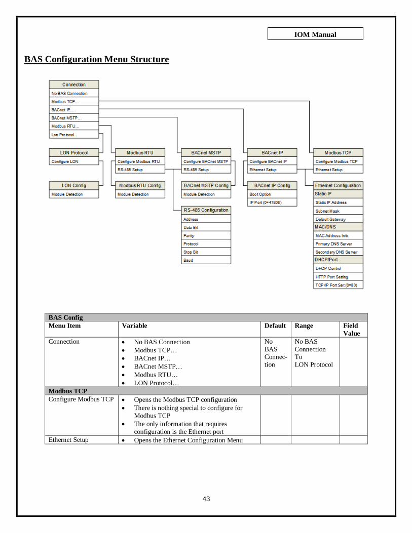
43
IOM Manual
BAS Configuration Menu Structure
BAS Config Menu Item Variable Default Range Field
Value Connection • No BAS Connection
• Modbus TCP… • BACnet IP… • BACnet MSTP… • Modbus RTU… • LON Protocol…
No BAS Connec-tion
No BAS Connection To LON Protocol
Modbus TCP Configure Modbus TCP • Opens the Modbus TCP configuration
• There is nothing special to configure for Modbus TCP
• The only information that requires configuration is the Ethernet port
Ethernet Setup • Opens the Ethernet Configuration Menu

44
IOM Manual
BACnet IP Configure BACnet IP • BACnet IP Configuration
Boot Option (Configure BACnet IP)
• No Action • Load BACnet E2 Defaults (loaded at next
system boot)
No Action
IP Port (Configure BACnet IP)
• Allows setting of specific BACnet IP port • A setting of 0 = 47808 • A setting of 65535 = BACnet stack running
only on PLC side
0 0 to 65535
Ethernet Setup • Opens the Ethernet Configuration Menu BACnet MSTP
Configure BACnet MSTP
• RS-485 module detection screen • Correct installation of the RS-485
communication module can be verified here
RS-485 Configuration • Opens the RS-485 Configuration Menu Modbus RTU
Configure Modbus RTU
• RS-485 module detection screen • Correct installation of the RS-485
communication module can be verified here
RS-485 Configuration • Opens the RS-485 Configuration Menu Lon Protocol
Configure Lon • Lon module detection screen • Correct installation of the Lon
communication module can be verified here
Ethernet Configuration Menu Item Variable Default Range Field
Value Static IP Address
(Static IP) • Static IP address set here 10.0.0.100 0.0.0.0
To 255.255.255.255
Subnet Mask (Static IP)
• Subnet Mask address set here 255.255. 255.0
0.0.0.0 To
255.255.255.255
Default Gateway (Static IP)
• Default Gateway address set here 10.0.0.1 0.0.0.0 To
255.255.255.255
MAC Address Info (MAC/DNS)
• Controller MAC address viewed here Varies 00:00:00:00:00:00 To
FF:FF:FF:FF:FF:FF
Primary DNS Server (MAC/DNS)
• Primary DNS Server address set here 8.8.8.8 0.0.0.0 To
255.255.255.255
Secondary DNS Server (MAC/DNS)
• Secondary DNS Server address set here 8.8.4.4 0.0.0.0 To
255.255.255.255
DHCP Control (DHCP/Port)
• DHCP addressing control enabled here DHCP Disabled
DHCP Disabled To
DHCP Enabled
HTTP Port Setting (DHCP/Port)
• HTTP Port set here • Setting of 0 = default port 80
0 0 to 65535
TCP/IP Port Setting (DHCP/Port)
• TCP/IP Port set here 502 0 to 65535

45
IOM Manual
RS-485 Configuration Menu Item Variable Default Range Field
Value Address • RS-485 address set here 1 0 To 255 Data Bit • Data Bit displayed here 8 8 to 8 Parity • RS-485 Parity set here Even None
Odd Even
Protocol • RS-485 communication protocol set here • If BACnet IP is the desired communication
protocol, this setting CANNOT be BACnet MSTP – The controller will only serve BACnet through one hardware port at a time
Modbus RTU
uNET Modbus RTU
BACnet MSTP
Stop Bit • RS-485 Stop Bit set here 1 1 to 2 Baud • RS-485 Baud rate set here 38,400 9,600
19,200 38,400 57,600 76,800 115,200

46
IOM Manual
BAS Point Export Table All Points READ ONLY
Supply Header Pressure Analog Value PSI 16-bit Int 9164 nvo SupPressSuction Header Pressure Analog Value PSI 16-bit Int 9165 nvo SucPressFlow Rate Analog Value GPM 16-bit Int 9166 nvo FlowRateRemote system Pressure Analog Value PSI 16-bit Int 9167 nvo RemPressSystem Speed - - - - nvo SysSpeedPump 1 Speed Analog Value % 16-bit Int 9168 - -Pump 2 Speed Analog Value % 16-bit Int 9169 - -Pump 3 Speed Analog Value % 16-bit Int 9170 - -Pump 4 Speed Analog Value % 16-bit Int 9171 - -Current Lead Pump Analog Value 16-bit Int 9172 nvo LeadPumpHigh System Shutdown Pressure Analog Value PSI 16-bit Int 9173 nvo HiShtdnPrsSystem Setpoint Analog Value PSI 16-bit Int 9174 nvo SysSetpointSystem Temperature - - - - nvo SysTempPump 1 Temperature Analog Value DegF 16-bit Int 9175 - -Pump 2 Temperature Analog Value DegF 16-bit Int 9176 - -Pump 3 Temperature Analog Value DegF 16-bit Int 9177 - -Pump 4 Temperature Analog Value DegF 16-bit Int 9178 - -Pump 1 Run Hours Analog Value Hours 32-bit Uint 9179 nvo P1RunHrsPump 2 Run Hours Analog Value Hours 32-bit Uint 9181 nvo P2RunHrsPump 3 Run Hours Analog Value Hours 32-bit Uint 9183 nvo P3RunHrsPump 4 Run Hours Analog Value Hours 32-bit Uint 9185 nvo P4RunHrsPump 1 Status Binary Value Off Running 16-bit Int 9187 nvo P1StatusPump 2 Status Binary Value Off Running 16-bit Int 9188 nvo P2StatusPump 3 Status Binary Value Off Running 16-bit Int 9189 nvo P3StatusPump 4 Status Binary Value Off Running 16-bit Int 9190 nvo P4StatusNo Flow Standby Status Binary Value Running Standby 16-bit Int 9191 nvo NFSBStatusLow Level Cutout Enable Binary Value Disabled Enabled 16-bit Int 9192 nvo LLCOEnableLow Level Cutout Alarm Binary Value Normal Alarm 16-bit Int 9193 nvo LLCOAlarmSystem Enable Binary Value Disabled Enabled 16-bit Int 9194 nvo SysEnablePump 1 Alarm Binary Value Normal Alarm 16-bit Int 9195 nvo P1AlarmPump 2 Alarm Binary Value Normal Alarm 16-bit Int 9196 nvo P2AlarmPump 3 Alarm Binary Value Normal Alarm 16-bit Int 9197 nvo P3AlarmPump 4 Alarm Binary Value Normal Alarm 16-bit Int 9198 nvo P4AlarmHigh System Pressure Alarm Binary Value Normal Alarm 16-bit Int 9199 nvo HSPAlarmLow Suction Shutdown Alarm Binary Value Normal Alarm 16-bit Int 9200 nvo LSSDAlarmPump 1 High Temperature Shutdown Alarm Binary Value Normal Alarm 16-bit Int 9201 nvo P1HiTmpPump 2 High Temperature Shutdown Alarm Binary Value Normal Alarm 16-bit Int 9202 nvo P2HiTmpPump 3 High Temperature Shutdown Alarm Binary Value Normal Alarm 16-bit Int 9203 nvo P3HiTmpPump 4 High Temperature Shutdown Alarm Binary Value Normal Alarm 16-bit Int 9204 nvo P4HiTmpLow System Pressure Alarm Binary Value Normal Alarm 16-bit Int 9205 nvo LSPAlmLow System Pressure Shutdown Alarm Binary Value Normal Alarm 16-bit Int 9206 nvo LSPShtdAlmRemote High Pressure Alarm Binary Value Normal Alarm 16-bit Int 9207 nvo RHiPrsAlmRemote Low Pressure Alarm Binary Value Normal Alarm 16-bit Int 9208 nvo RLoPrsAlmSupply Pressure Transmitter Failure Binary Value Normal Alarm 16-bit Int 9209 - -Suction Pressure Transmitter Failure Binary Value Normal Alarm 16-bit Int 9210 - -Pump 1 Temperature Sensor Failure Binary Value Normal Alarm 16-bit Int 9211 - -Pump 2 Temperature Sensor Failure Binary Value Normal Alarm 16-bit Int 9212 - -Pump 3 Temperature Sensor Failure Binary Value Normal Alarm 16-bit Int 9213 - -Pump 4 Temperature Sensor Failure Binary Value Normal Alarm 16-bit Int 9214 - -Remote Pressure Transmitter Failure Binary Value Normal Alarm 16-bit Int 9215 - -Flow Transmitter Failure Binary Value Normal Alarm 16-bit Int 9216 - -VFD In Manual Alarm Binary Value Normal Alarm 16-bit Int 9217 nvoVFDManAlmHigh Suction Shutdown Alarm Binary Value Normal Alarm 16-bit Int 9218 nvo HSucShtdn
----Lon Point Data----
Type DescriptionPoint Description BACnet PointUnits /
Inactive Active
--------BACnet Point Data-------- -Modbus Point Data-
TypeDecimal Address
Once all BAS data has been configured, Escape all the way out to the main menu and cycle power to the controller.

47
IOM Manual
Schneider Electric Altivar 212

48
IOM Manual
Allen Bradley PowerFlex 523

49
IOM Manual
Schneider Magellis STU 655/855
Cleaning the Display
Cleaning the Gasket
• With the gasket in place, the unit meets IP65 rating. • Change the gasket at least once a year, or as soon as scratches or dirt become visible. • During normal maintenance and reinstallation, check the gasket for dirt and scratches.
Inserting the Gasket
NOTICE: The gasket must be inserted correctly into the groove to comply with IP65. The upper surface of the gasket should protrude approximately 2 mm (0.08 in.) out from the groove. Verify that the gasket is
correctly inserted before installing the unit into a panel. NOTICE: Verify the gasket seam is inserted into the straight bottom section of the groove. Inserting it into a corner may
lead to eventual tearing.
Periodic Check Points Electrical Specifications
The input voltage must be within 20.4 to 28.8 Vdc.
Related Items • Verify that all power cords and cables are connected properly and that there are no loose cables. • Verify that all the mounting brackets are holding the unit securely. • Verify that there are no scratches or traces of dirt on the installation gasket.
CAUTION EQUIPMENT DAMAGE
• Power off the unit before cleaning. • Do not use hard or pointed objects to operate the touch panel, since it can
damage the panel surface. • Do not use paint thinner, organic solvents, or strong acid compounds to clean
the unit. Failure to follow these instructions can result in equipment damage.

50
IOM Manual
Booster Installation Location • Place the pump as near the liquid source as practical. Place below level of liquid for automatic re-priming capability. • Allow adequate space for servicing and ventilation. Protect the unit from weather and water damage due to rain, flooding
or freezing temperatures. • Protect the pump and piping from freezing temperatures. • Allow adequate space around the unit for service and ventilation.
Close-Coupled Units • For vertical operation, the motor should be fitted with a drip cover or otherwise protected against liquid entering the motor
(rain, spray, condensation, etc.)
NOTICE: DO NOT INSTALL WITH MOTOR BELOW PUMP. ANY LEAKAGE OR CONDENSATION WILL AFFECT THE MOTOR.
Piping Piping Suction
NOTICE: DO NOT USE THE BALL VALVE TO THROTTLE PUMP. THIS MAY CAUSE LOSS OF PRIME,
EXCESSIVE TEMPERATURES AND DAMAGE TO PUMP, VOIDING WARRANTY.
Wiring & Grounding
• Install, ground and wire according to local and National
Electrical Code Requirements. • Install an all leg electrical power disconnect switch near
the pump. • Disconnect and lockout electrical power before installing
or servicing the pump. • Electrical supply MUST match pump’s nameplate
specifications. Incorrect voltage can cause fire, damage motor and void the warranty.
• Motors without built-in protection MUST be provided with contactors and thermal overloads for single phase motors, or starters with heaters for three phase motors. See motor nameplate.
• Use only copper wire to motor and ground. The ground wire MUST be at least as large as the wire to the motor. Wires should be color coded for ease of maintenance.
• Follow motor manufacturer’s wiring diagram on the motor nameplate or terminal cover carefully. FAILURE TO PERMANENTLY GROUND THE PUMP, MOTOR AND CONTROLS BEFORE CONNECTING TO ELECTRICAL POWER CAN CAUSE SHOCK, BURNS OR DEATH.
WARNING
HAZARDOUS VOLTAGE

51
IOM Manual
Rotation
NOTICE: INCORRECT ROTATION MAY DAMAGE THE PUMP AND VOID THE WARRANTY.
o For frame mounted units, switch power on and off quickly to observe rotation. o On close coupled units, remove motor end plug or cover to observe rotation. o To reverse three phase motor rotation, interchange any two power supply leads.
Operation
NOTICE: DO NOT RUN PUMP DRY OR SEAL WILL BE DAMAGED.
Check the piping after stabilizing the system at normal operating conditions. Adjust the pipe supports if necessary. Booster piping connections MUST NOT be used to SUPPORT EXTERNAL PIPING.
Maintenance
SPLASHING OR IMMERSING OPEN DRIP PROOF MOTORS IN FLUID
CAN CAUSE FIRE, SHOCK, BURNS OR DEATH.
OPERATION AT OR NEAR ZERO FLOW CAN CAUSE EXTREME HEAT, PERSONAL INJURY OR
PROPERTY DAMAGE.
FAILURE TO DISCONNECT AND LOCKOUT ELECTRICAL POWER
BEFORE ATTEMPTING ANY MAINTENANCE CAN CAUSE SHOCK,
BURNS OR DEATH.
FAILURE TO RELIEVE SYSTEM PRESSURE AND DRAIN SYSTEM
BEFORE ATTEMPTING ANY MAINTENANCE CAN CAUSE
PROPERTY DAMAGE, PERSONAL INJURY AND
DEATH.
TURN OFF ALL POWER BEFORE OPENING CABINET. ELECTRIC
ARC FLASH HAZARD WILL CAUSE SEVERE INJURY OR
DEATH. FOLLOW ALL REQUIREMENTS IN NFPA 70E FOR SAFE WORK PRACTICES
AND FOR PERSONAL PROTECTIVE EQUIPMENT.
IF PIPING CONTAINS
HAZARDOUS OR TOXIX FLUIDS, SYSTEM MUST BE
FLUSHED PRIOR TO PERFORMING SERVICE.

52
IOM Manual
Close-Coupled Unit Bearings are part of the motor. For Lubrication information, refer to motor manufacturer’s instructions.
Seasonal Service • To REMOVE pump from service, remove drain plug and drain all unprotected piping. • To RETURN pump to service, replace drain plug using Teflon™ tape or equivalent on male threads. • Reconnect suction line if removed. Examine union and repair if necessary. • Refer to OPERATION section of manual.
NOTICE: For disassembly and reassembly information and instructions, refer to the applicable Goulds pump manual.
Monthly Maintenance
Touchscreen
• Make sure that the touchscreen controls are operating efficiently. • Review the alarm history and data log history.
Motor Lubrication
• In grease-filled bearings, check that the inside of the motor is not overfilled.
BEFORE SERVICING VARIABLE FREQUENCY
DRIVES, REMOVE ALL POWER, WAIT 15 MINUTES. HAZARD OF ELECTRIC SHOCK,
EXPLOSION, OR ARC FLASH.
THE DRY TYPE DISTRIBUTION TRANSFORMER (IF USED) MUST ONLY BE INSTALLED AND
SERVICED BY QUALIFIED ELECTRICAL PERSONNEL. HAZARD OF ELECTRIC SHOCK OR
BURN. TURN OFF POWER SUPPLYING THIS EQUIPMENT BEFORE WORKING INSIDE
CONTROL CABINET.
MOTOR MUST BE GROUNDED IN ACCORDANCE WITH THE NATIONAL
ELECTRICAL CODE AND LOCAL CODES BY TRAINED PERSONNEL TO PREVENT
SERIOUS ELECTRICAL SHOCKS. TO SERVICE MOTOR, DISCONNECT POWER SOURCE
FROM MOTOR AND ANY ACCESSORY DEVICES AND ALLOW MOTOR TO COME TO
A COMPLETE STANDSTILL.
HAZARDOUS VOLTAGE. DISCONNECT AND LOCKOUT POWER TO PUMP PRIOR TO
PERFORMING ANY SERVICE OR MAINTENANCE. REFER TO INSTRUCTION MANUAL FOR PROPER INSTALLATION. ELECTRICAL AND PLUMBING
INSTALLATION MUST CONFORM TO LOCAL AND NATIONAL CODES. DO NOT RUN PUMP DRY. DO
NOT OPERATE AT CLOSED DISCHARGE. FAILURE TO FOLLOW WARNING INSTRUCTIONS MAY RESULT IN PERSONAL INJURY INCLUDING
DEATH AND PROPERTY DAMAGE.

53
IOM Manual
Sound/Visual Inspection
• Watch/listen for any rubbing, grinding, or electrical arcing in the system. Look for anything that is binding or appears unusual.
NOTICE: Harmonic vibrations will occur with the pumps and motor. Excessive vibration or noise can cause problems and require immediate service. If excessive vibration is found, do not operate the pump.
• Ensure that the eMVP/MVP is operating in temperatures between 35°F and 104°F. • Ensure that water, grease or oil is not leaking. • Ensure that no hardware is loose.
Troubleshooting Guide
Motor Not Running Cause Solution
Motor thermal protector tripped Let motor cool, then reset the thermal protector.
Open circuit breaker or blown fuse Check circuit breaker and fuses. Impeller binding Make sure the pump can be turned by hand.
Check for a bound impeller. Motor improperly wired Securely connect motor wiring.
Defective motor Repair or replace the motor.
Excessive Power Consumption Cause Solution
Impeller binding Make sure the pump can be turned by hand. Check for a bound impeller.
Incorrect impeller diameter Trim or replace the impeller. Discharge head too low- excessive flow
rate Check the discharge piping and valves. Make
sure that pipes and plugs are not plugged. Make sure that the isolation valves are open and that
there are no clogs.
DISCONNECT AND LOCKOUT ELECTRICAL POWER BEFORE
ATTEMPTING ANY MAINTENANCE. FALURE TO DO SO CAN CAUSE A SHOCK, BURN
OR DEATH.

54
IOM Manual
Little or No Liquid Delivered Cause Solution
Pump is not primed, air or gases in pump Make sure that the pump station is properly primed. Make sure that pumps and components
are correctly filled with water. Discharge, suction plugged or valve
closed Check the discharge piping and valves. Make
sure that pipes and plugs are not plugged. Make sure that the isolation valves are open and that
there are no clogs. Incorrect rotation (3 phase only) Inspect the pump rotation. The pump volute
will indicate the proper rotation. Low voltage or phase loss Have the incoming power and voltage checked
by a qualified electrician. Impeller worn or plugged Bring the pump to an authorized pump repair
facility. System head too high Ensure that the valve or pump is not closed.
(NPSH) Net Positive Suction Head too low – Excessive Suction lift or losses
Check the NPSH. Ensure that proper flooded conditions or positive pressure is being
delivered to the pump station. Watch for air in the supply lines. Ensure that supply tanks are
correctly filled. Incorrect impeller diameter Trim or replace the impeller.
Excessive Noise/Vibration Cause Solution
Impeller binding Make sure the pump can be turned by hand. Check for a bound impeller.
Pump is not primed, air or gases in pump Make sure that the pump station is properly primed. Make sure that pumps and components
are correctly filled with water. Discharge, suction plugged or valve
closed Check the discharge piping and valves. Make
sure that pipes and plugs are not plugged. Make sure that the isolation valves are open and that
there are no clogs. Impeller worn or plugged Bring the pump to an authorized pump repair
facility. (NPSH) Net Positive Suction Head too low – Excessive Suction lift or losses
Check the NPSH. Ensure that proper flooded conditions or positive pressure is being
delivered to the pump station. Watch for air in the supply lines. Ensure that supply tanks are
correctly filled. Discharge head too low- excessive flow
rate Ensure that there is no excessive water consumption or leakage in the system.
Worn bearing Bring the pump to an authorized pump repair facility.
Pump, motor, or piping loose Properly tighten all fasteners and components.

55
IOM Manual
Replacement Parts
Hyfab Model MVP Pressure Booster

56
IOM Manual
Typical Goulds 3656-S Pump End
Typical Cla-Val Angle Check Valve
A Stem NutB Diaphragm WasherC DiaphragmD StemE Spacer WashersF Disc GuideG DiscH Disc Retainer

57
IOM Manual
NOTE: ALL PARTS TABLES REPRESENT STANDARD CONSTRUCTION ITEMS. TO INSURE CORRECT APPLICATIONS, CONTACT YOUR REPRESENTATIVE WITH THE UNIT’S PRD NUMBER, TYPICALLY LOCATED ON THE CONTROLLER ENCLOSURE.
WARNING: Control panel items (VFD, Controller, Touchscreen) require Hyfab-specific programming. Failure to obtain the appropriate programming will result in damage to the equipment.
1 Cla-Val, Includes Parts A-H (Illustrated, Page 56) 2 Cla-Val, Includes Parts C, E, and G Only (Illustrated, Page 56)
MVP-630 MVP-850 MVP-875 MVP-8100 MVP-81501
VFD 208V Allen Bradley 25A-B011N104 25A-B017N104 25A-B024N104 25A-B032N104 25A-B048N104Schneider Electric ATV212HU22M3X ATV212HU40M3X ATV212HU55M3X ATV212HU75M3X ATV212HD11M3X
460V Allen Bradley 25A-D6P0N104 25A-D010N104 25A-D013N104 25A-D017N104 25A-D030N104Schneider Electric ATV212HU22N4 ATV212HU40N4 ATV212HU55N4 ATV212HU75N4 ATV212HD11N4
TouchscreenController
BAS Module (OPT.)2
2.0 Pump/Motor Assembly 3BF1HBC3.HFVFD 5BF1JBH3.HFVFD 5BF1KBG3.HFVFD 5BF1LBC3.HFVFD 5BF1MBB3.HFVFD2.1 Volute 1K992.2 Impeller 2K123 2K769 2K350 2K349 2K3472.3 Motor Adaptor 1K1112.4 Casing Wear Ring2.5 Impeller Bolt2.6 Impeller Washer2.7 Impeller Key2.8 Volute O-Ring 5K2072.9 Mechanical Seal
2.10 Shaft Sleeve2.11 Casing Plug2.12 Hex Casing Bolt2.13 Hex Motor Adapter Bolt2.14 Motor EJMM3158T EJMM3212T EJMM3219T EJMM3312T EJMM3314T
3125 Degree Relief
Compression Fitting4
4.04.1 Diaphragm Assembly4.2 Repair Kit
5
6
7
8
STANDARD MVP BOOSTER COMPONENTS/COMMON REPLACEMENT PARTS
C-138CHECK VALVE
CONTROL PANEL
CLOSE-COUPLED PUMPS
HMISTU655TM172PBG28R
TM171ARS485 - Not Installed As Standard
1K103
13K69 (Quantity of 8)
TRANSDUCER WIRESchneider Electric XZCPV1141L5
LED DISPLAY/SWITCHSchneider Electric ZMLPA1P2SW
PRESSURE TRANSDUCERSchneider Electric XMLP300PD230Q
TEMPERATURE SENSORMamac TE-703-A-8-A-6/11
Goulds
Baldor
Cla-Val20061604J1
13K69 (Quantity of 4)
1K1171K1154K68
13K4313L394K11
5K20510K274K66
6K2 (Quantity of 4)
91698-05A2
THERMAL RELIEF VALVE242-000000-125
81-12-1F

58
IOM Manual
WARNING: Control panel items (VFD, Controller, Touchscreen) require Hyfab-specific programming. Failure to obtain the appropriate programming will result in damage to the equipment.
1 Cla-Val, Includes Parts A-H (Illustrated, Page 56) 2 Cla-Val, Includes Parts C, E, and G Only (Illustrated, Page 56)
MVP-750 MVP-775 MVP-7100 MVP-71501
VFD 208V Allen Bradley 25A-B017N104 25A-B024N104 25A-B032N104 25A-B048N104Schneider Electric ATV212HU40M3X ATV212HU55M3X ATV212HU75M3X ATV212HD11M3X
460V Allen Bradley 25A-D010N104 25A-D013N104 25A-D017N104 25A-D030N104Schneider Electric ATV212HU40N4 ATV212HU55N4 ATV212HU75N4 ATV212HD11N4
TouchscreenController
BAS Module (OPT.)2
2.0 Pump/Motor Assembly 4BF1JBH3-B 4BF1KBF3-B 4BF1LBD3-B 4BF1MBB3-B2.1 Volute 1K1012.2 Impeller 2K1108 2K1106 2K1104 2K11022.3 Motor Adaptor 1K1202.4 Casing Wear Ring2.5 Impeller Bolt2.6 Impeller Washer2.7 Impeller Key2.8 Volute O-Ring2.9 Mechanical Seal
2.10 Shaft Sleeve2.11 Casing Plug2.12 Hex Casing Bolt2.13 Hex Motor Adapter Bolt2.14 Motor EJMM3212T EJMM3219T EJMM3312T EJMM3314T
3125 Degree Relief
Compression Fitting4
4.04.1 Diaphragm Assembly4.2 Repair Kit
5
6
7
8
LED DISPLAY/SWITCHZMLPA1P2SW
XMLP300PD230Q
CHECK VALVE81-12-3B
Baldor
C2523D1
91698-11J2
CONTROL PANEL
MVP BOOSTER COMPONENTS/COMMON REPLACEMENT PARTS
CLOSE-COUPLED PUMPS
1K118
TE-703-A-8-A-6/11
PRESSURE TRANSDUCER
TEMPERATURE SENSOR
4K666K2 (Quantity of 4)
13K69 (Quantity of 8)13K69 (Quantity of 4)
THERMAL RELIEF VALVE
C-138242-000000-125
Mamac
Cla-Val
Schneider Electric XZCPV1141L5TRANSDUCER WIRE
Schneider Electric
Schneider Electric
10K27
Goulds
HMISTU655TM172PBG28R
4K7013K4313L394K11
5K205
TM171ARS485 - Not Installed As Standard

59
IOM Manual
Hyfab Model eMVP Pressure Booster (Using 5SV-22SV Goulds e-SV Pumps)

60
IOM Manual
Typical Goulds e-SV, Models 5SV – 22SV
CONTINUED ON NEXT PAGE
1VFD
208V 460V 208V 460V25A-B5P0N104 25A-D2P3N104 ATV212H075M3X ATV212H075N425A-B8P0N104 25A-D4P0N104 ATV212HU15M3X ATV212HU15N4
25A-B011N104 25A-D6P0N104 ATV212HU22M3X ATV212HU22N425A-B017N104 25A-D010N104 ATV212HU40M3X ATV212HU40N425A-B024N104 25A-D013N104 ATV212HU55M3X ATV212HU55N425A-B032N104 25A-D017N104 ATV212HU75M3X ATV212HU75N425A-B048N104 25A-D030N104 ATV212HD11M3X ATV212HD11N4Consult Factory 25A-D030N104 ATV212HD15M3X ATV212HD15N4Consult Factory 25A-D037N114 ATV212HD18M3X ATV212HD18N4Consult Factory 25A-D043N114 ATV212HD22M3X ATV212HD22N4
TouchscreenController
BAS Module (OPT.)
HP
11.5235
7.51015202530
VEM31158VEM31155VEM31120VEM31115
VEM3314TVEM2514TVEM2516T
Consult Factory
VEM4106TConsult FactoryConsult Factory
VEM3212TVEM3219TVEM3312T
MOTORS - FRAME VALUES REFERENCE IDENTIFIED MODELS ONLY
230V/460V, USABLE AT 208 230V/460V, USABLE AT 208VEM3545VEM3550VEM3555VEM3559
VEM3613TVEM3616T
250TC
ODP - PE TEFC - PE
Consult Factory
VEM3711TVEM3713T
Frame Size
56C
180TC
210TC
CONTROL PANELeMVP BOOSTER COMPONENTS/COMMON REPLACEMENT PARTS
202530
HMISTU655TM172PBG28R
Schneider ElectricAllen Bradley
32
57.5
HP1
1.5
10
TM171ARS485 - Not Installed As Standard
15

61
IOM Manual
WARNING: Control panel items (VFD, Controller, Touchscreen) require Hyfab-specific
programming. Failure to obtain the appropriate programming will result in damage to the equipment.
1 Cla-Val, Includes Parts A-H (Illustrated, Page 56) 2 Cla-Val, Includes Parts C, E, and G Only (Illustrated, Page 56)
22.0 5SV 10SV 15SV 22SV2.1 Pump Body 1L655
N/A2.2 Impeller 2L921 2L923 2L925 2L9272.3 Diffuser 3L57 3L592.4 Casing2.5 Shaft2.6 Adapter2.7 Base 1K709
N/A2.8 Coupling2.9 Seal Plate 1L842
2.10 Mechanical Seal 10K1682.11 Casing O-Rings2.12 Coupling Guard2.13 Shaft Bushing 4L6022.14 Vent Plug2.15 Tie Rods2.16 Wear Ring2.17 Seal Gland 1K669
3125 Degree Relief
Compression Fitting4.0 1-1/2"
81-12-13CN/A
4.1 Diaphragm Assembly C2522F1
N/A4.2 Repair Kit 91698-04D2
N/A5
6
7
8
10K1695K510
SEE e-SV REPAIR PARTS MANUAL FOR PUMP/MOTOR FRAME TABLE
SEE e-SV REPAIR PARTS MANUAL FOR STAGING TABLESEE e-SV REPAIR PARTS MANUAL FOR PUMP/MOTOR FRAME TABLE
Gouldse-SV PUMPS, 5SV - 22SV
Cla-ValNPT
SEE e-SV REPAIR PARTS MANUAL FOR PUMP/MOTOR FRAME TABLE1L844
1L6591L665
T Code (304SS Oval)G Code (Cast Iron 250#)
3L61
LED DISPLAY/SWITCH
PRESSURE TRANSDUCER
TEMPERATURE SENSOR
6L19SEE e-SV REPAIR PARTS MANUAL FOR STAGING TABLE
N/A - SEE DIFFUSER1K701
Schneider Electric
300#NPT
300#NPT
300#
2"81-12-1F
81-12-14B20061604J1
91698-05A2
N/A - SEE PUMP BODY
TRANSDUCER WIREXZCPV1141L5
TE-703-A-8-A-6/11
XMLP300PD230Q
ZMLPA1P2SW
Schneider Electric
Mamac
Schneider Electric
4L603
T Code (304SS Oval)G Code (Cast Iron 300#)
1K711
242-000000-125ThermomegatechTHERMAL RELIEF VALVE
C-138

62
IOM Manual
Hyfab Model eMVP Pressure Booster
(Using 33SV-92SV Goulds e-SV Pumps)

63
IOM Manual
Typical Goulds e-SV, Models 33SV – 92SV

64
IOM Manual
WARNING: Control panel items (VFD, Controller, Touchscreen) require Hyfab-specific programming. Failure to obtain the appropriate programming will result in damage to the equipment.
e-SV repair parts listed above represent the most commonly requested items. For A More Comprehensive Parts List, See e-SV Repair Parts Manual
1VFD
208V 460V 208V 460V25A-B017N104 25A-D010N104 ATV212HU40M3X ATV212HU40N425A-B024N104 25A-D013N104 ATV212HU55M3X ATV212HU55N425A-B032N104 25A-D017N104 ATV212HU75M3X ATV212HU75N425A-B048N104 25A-D030N104 ATV212HD11M3X ATV212HD11N4Consult Factory 25A-D030N104 ATV212HD15M3X ATV212HD15N4Consult Factory 25A-D037N114 ATV212HD18M3X ATV212HD18N4Consult Factory 25A-D043N114 ATV212HD22M3X ATV212HD22N4
TouchscreenController
BAS Module (OPT.)
HP
57.51015202530
210TCVEM3219TVEM3312T
230V/460V, USABLE AT 208230V/460V, USABLE AT 208VEM3613TVEM3616TVEM3711T
MOTORS - FRAME VALUES REFERENCE IDENTIFIED MODELS ONLYODP - PE TEFC - PEFrame Size
180TC VEM3212T
Consult Factory Consult Factory Consult Factory
VEM3314T VEM3713T250TC VEM2514T VEM4106T
VEM2516T Consult Factory
TM172PBG28RTM171ARS485 - Not Installed As Standard
15202530
HMISTU655
57.510
eMVP BOOSTER COMPONENTS/COMMON REPLACEMENT PARTSCONTROL PANEL
Allen Bradley Schneider ElectricHP
22.0 33SV 46SV 66SV 92SV2.4 Casing O-Ring2.5 Mechanical Seal
2.15 Tie Rods2.17 Vent Plug (Not Shown)2.19 Pump Head2.20 Impeller 2L899 2L900 2L901 2L9022.21 2L903 2L904 2L905 2L9062.27 Casing2.29 Seal Housing2.32 Shaft Bushing Spacer2.36 Coupling Guard2.37 Shaft2.42 Pump Body 1L640 1L642
1L641 1L6432.44 Adapter2.45 Coupling2.47 Wear Ring 15L47 15L48 15L49 15L50
1L6441L645
Reduced DiameterSEE e-SV REPAIR PARTS MANUAL FOR STAGING TABLE
SEE e-SV REPAIR PARTS MANUAL FOR PUMP/MOTOR FRAME TABLE
10K199
4L510
6L53
G Code (Cast Iron 250#)
Full Diameter
SEE e-SV REPAIR PARTS MANUAL FOR STAGING TABLE
1L629
1L632 1L633
SEE e-SV REPAIR PARTS MANUAL FOR STAGING TABLESEE e-SV REPAIR PARTS MANUAL FOR PUMP/MOTOR FRAME TABLE
e-SV PUMPS, 33SV - 92SVGoulds
G Code (Cast Iron 125#)
5K407 5K408

65
IOM Manual
1 Cla-Val, Includes Parts A-H (Illustrated, Page 56) 2 Cla-Val, Includes Parts C, E, and G Only (Illustrated, Page 56)
33SV 46SV 66SV 92SV3
125 Degree ReliefCompression Fitting
44.0 2-1/2" 3"
81-12-3B 81-12-9J 81-12-24K 81-12-24K81-12-15A 81-12-16K 81-12-21C 81-12-21C
4.1 Diaphragm Assembly C2523D1 C2525J1 200616C1 200616C1
20061605H1 20061606G1 20061612J1 20061612J1
4.2 Repair Kit 91698-11J2 91698-12G2 91698-13E2 91698-13E2
9817921B2 9817922K2 9817922K2
5
6
7
8
THERMAL RELIEF VALVEThermomegatech 242-000000-125
C-138
150#300#150#300#
300#
Cla-Val 4"
Schneider Electric ZMLPA1P2SWPRESSURE TRANSDUCER
Schneider Electric XMLP300PD230QTEMPERATURE SENSOR
CHECK VALVE
150#
LED DISPLAY/SWITCH
Mamac TE-703-A-8-A-6/11TRANSDUCER WIRE
Schneider Electric XZCPV1141L5
Kit Part NumberFlange Adapter Kits MVP-FK3
MVP-FK4MVP-FK6
Copper Transitions MVP-TF3MVP-TF4
N/AFlexible Transition N/A
Fittings MVP-FTC-3C
MVP-FTC-4C
MVP-FTC-4F
N/AEasy Tank Connect MVP-TC-3
MVP-TC-4MVP-TC-66"
Description
Grooved Concentric Fitting with Cold fill ValveReplaces End Cap on Discharge Header when Used
Flexible Transitions, 4" Header to 4" Copper Stub SystemConnection (Pair), Includes Grooved Couplings
Connection (Pair), Includes Grooved CouplingsFlexible Transitions, 4" Header to 3" Copper Stub System
Flexible Transitions, 4" Header to 4" 150# Flange System
Booster Header Size
6"3"4"
Grooved Stub Ends With 150# Backer Flanges (Pair)Includes Stainless to Stainless Grooved Couplings
Grooved (Header Connection) Copper Stub Ends (Pair)Includes Copper to Stainless Grooved Couplings
3"4"
Connection (Pair), Includes Grooved Couplings
6"3"4"6"3"4"
OPTIONAL BOOSTER ACCESSORIES

66
IOM Manual
Frequently Asked Questions
• Capital ‘E’ is on the Altivar 212 drive display:
o Press the Stop button two times in rapid succession to reset VFD. o (The capital ‘E’ will only appear when the Stop button on the VFD is pressed once to stop the drive)
• System is connected, but will not operate: o The system may be set at an incorrect pressure. o If the setpoint is too low, increase it to the appropriate setpoint.
(The default setpoint of most systems is 50 psi, unless otherwise requested) o If unsure how to adjust the setpoint, review the instructions in this manual.
• EPHI on the Altivar 212 drive display (Input phase loss) VFD alarm condition is present: o This indicates an input phase failure.
An input phase failure can be common after storms and electrical surges. o If input power is OK, A system reset will clear the alarm.
• Touchscreen is not operating: o An unlit touchscreen may indicate no power to the panel. o To preserve display life, display backlight powers down after 10 minutes of inactivity. Touching the display
area will power up the display, if it has timed out.
• System is in High System Pressure Shutdown: o Verify that supply pressure sensor is wired and functioning properly (indicating accurate system pressure). o Check High Discharge Pressure Shutdown (HPSD) setting. It may be set too low. o Verify that system has been tuned via PID settings to ensure smooth, adequate responses to system pressure
fluctuations.
• EPHO on the Altivar 212 drive display (Output phase loss) VFD alarm condition is present: o This indicates a problem with the drive output.
• Pump is making loud noises: o Loud noise in single-stage pumps may indicate low suction pressure. o Make sure that air is totally removed from the system. o This could indicate an internal problem with the pump that requires a pump service technician to remedy.
• Output pressure of the pump is fluctuating: o Continuous pressure fluctuations of more than 8 psi indicate that the PID settings may need to be adjusted. o Check the air pressure charge in the hydropneumatic tank. o Check the PID Tuning.
If the booster is overreacting to system pressure fluctuations then the Proportional Gain should be reduced. If the booster isn’t reacting enough then the Proportional Gain should be increased. Make small changes. A little change in the Proportional Gain goes a long way.
The Integral may need to be adjusted as well. The Integral is constantly increasing, or reducing the speed of the system to meet setpoint. A larger Integral results in slower increases/decreases.
The Proportional and Integral should be adjusted so that the booster reacts to system requirement fluctuations as quickly and as accurately as possible. On a significant fluctuation, the Proportional is responsible for the initial booster reaction and the Integral works to get the booster on setpoint. Small system fluctuations are handled by the Integral, for the most part.
Isolate the tank from the system and check: • PID Tuning • SetPoint • Restart Pressure

67
IOM Manual
Additional Components
Baldor Motors Baldor Motor IOMs are available at http://www.baldor.com/resources-and-support/download-center#area=%22manuals%22 Cla-Val Check Valves Cla-Val Check Valve Literature is available at: http://www.cla-val.com/81-02-681-02-check-valve-p-127.html Goulds Model 3656-S, Model e-SV Pumps 3656-S Literature is available at: http://goulds.com/centrifugal-pumps-boosters/single-stage-end-suction/3656-s3756-s-group-cast-iron-bronze-pumps/#product-tab-literature e-SV Literature is available at: http://goulds.com/centrifugal-pumps-boosters/multi-stage-pumps/esv-series/#product-tab-literature Magelis HMI HMI Literature is available at: http://www.schneider-electric.us/en/download/document/EAV15984/ Modicon Controller Series Controller Literature is available at: http://www.schneider-electric.com/en/product/TM172PBG28R/modicon-m172-performance-blind-28-i-os%2C-ethernet%2C-modbus/?range=62420-modicon-m171-m172&node=1427133103-modicon-m171-m172 Square D Altivar 212 VFD ATV212 Literature is available at: http://www.schneider-electric.us/en/download/doc-type/1555855-User%20guide/?category=66009262-AC+Drives+and+Soft+Starters&range=60162-Altivar+212+Drive Allen Bradley PowerFlex 523 VFD PF523 Literature is available at: http://ab.rockwellautomation.com/Drives/PowerFlex-523#documentation Therm-Omega-Tech Econo/HAT-RA Temperature Relief Valve Literature is available at: http://www.thermomegatech.com/product/econohat-ra/

68
IOM Manual
Warranty
HYFAB Packaged Systems Warranty
HYFAB warrants for a period of eighteen (18) months from date of shipment from its factory or
one (1) year from date of installation, whichever occurs first, that all Products furnished by HYFAB are free from defects in materials and workmanship.
HYFAB’s liability for any breach of this Warranty shall be limited solely to replacement or repair,
at the sole option of HYFAB, of any part or parts found to be defective during the Warranty period provided the Product is properly installed and is being used as originally intended. Buyer must notify HYFAB of any breach of this Warranty within the aforementioned Warranty period:
defective parts must be shipped by Buyer to Seller with transportation charges prepaid.
IT IS EXPRESSLY AGREED THAT THIS SHALL BE THE SOLE AND EXCLUSIVE REMEDY OF THE BUYER. UNDER NO CIRCUMSTANCES SHALL HYFAB BE LIABLE FOR ANY
COSTS, LOSS EXPENSE DAMAGES, SPECIAL DAMAGES, INCIDENTAL DAMAGES OR CONSEQUENTIAL DAMAGES ARISING DIRECTLY OR INDIRECTLY FROM THE DESIGN,
MANUFACTURE, SALE, USE OR REPAIR OF THE PRODUCT WHETHER BASED UPON WARRANTY, CONTRACT, NEGLIGENCE OR STRICT LIABILITY. IN NO EVENT WILL
LIABILITY EXCEED THE PURCHASE PRICE OF THE PRODUCT. THE WARRANTY AND LIMITS OF LIABILITY CONTAINED HEREIN ARE IN LIEU OF ALL OTHER WARRANTIES
AND LIABILITIES, EXPRESSED OR IMPLIED. ALL IMPLIED WARRANTIES OF MERCHANTABILITY AND FITNESS FOR A PARTICULAR PURPOSE ARE HEREBY
DISCLAIMED BY SELLER AND EXCLUDED FROM THIS WARRANTY.
HYFAB neither assumes nor authorizes any person to assume for it, any other Warranty obligation in connection with the sale of the Product. This Warranty shall not apply to any Product or parts of Products which (a) have been repaired or altered outside of HYFAB’s
facilities; or (b) have been subject to misuse, negligence or accident; or (c) have been used in a manner contrary to HYFAB’s instructions.
In the case of products not manufactured by HYFAB, there is no warranty from HYFAB, but
HYFAB will extend to the Buyer any Warranty of Seller's supplier of such products.
HYFAB
206 Seneca Road Greensboro, NC 27406 Phone: 888-902-8324 Fax: 800-377-8792 www.hyfabco.com
eMVP/MVP
Modular Variable Speed Pressure Boosters with M172 v5.xx Software
September 2017
Version A