
Emulsion Jet-in-Crossflow Penetration at High Pressure · PDF file ·...
10
ILASS Americas 26th Annual Conference on Liquid Atomization and Spray Systems, Portland, OR, May 2014 Emulsion Jet-in-Crossflow Penetration at High Pressure Conditions G.A. Gomez, C.D Bolszo and V.G. McDonell 1 Department of Mechanical and Aerospace Engineering University of California, Irvine Irvine, CA 92697-3550 USA Abstract Average top edge trajectory correlations for jets of neat liquids have been developed over the years. The current work focuses on the penetration behavior of a plain jet of water-in-oil emulsion in a high pressure environment. The current endeavor investigates the question of whether the attributes of the emulsion require modification to typical penetration correlations. A total of 24 emulsion jet-in-crossflow tests were performed with varying water to oil rati- os, ambient pressures of 2-8 atm, and jet to crossflow momentum ratios from 50 to 120. High speed videos were obtained and analyzed using averaging and edge filtering methods to extract the windward edge of the plume. The averaged and filtered image was then used for top edge trajectory tracing to up to 40 mm downstream of the injec- tion point. Overall it was found that additional parameters were not necessary to capture the behavior of the emul- sions in terms of penetration into the crossflow for the range of conditions studied. 1 Corresponding Author, [email protected]
Transcript of Emulsion Jet-in-Crossflow Penetration at High Pressure · PDF file ·...
ILASS Americas 26th Annual Conference on Liquid Atomization and Spray Systems, Portland, OR, May 2014
Emulsion Jet-in-Crossflow Penetration at High Pressure Conditions
G.A. Gomez, C.D Bolszo and V.G. McDonell1 Department of Mechanical and Aerospace Engineering
University of California, Irvine Irvine, CA 92697-3550 USA
Abstract
Average top edge trajectory correlations for jets of neat liquids have been developed over the years. The current work focuses on the penetration behavior of a plain jet of water-in-oil emulsion in a high pressure environment. The current endeavor investigates the question of whether the attributes of the emulsion require modification to typical penetration correlations. A total of 24 emulsion jet-in-crossflow tests were performed with varying water to oil rati-os, ambient pressures of 2-8 atm, and jet to crossflow momentum ratios from 50 to 120. High speed videos were obtained and analyzed using averaging and edge filtering methods to extract the windward edge of the plume. The averaged and filtered image was then used for top edge trajectory tracing to up to 40 mm downstream of the injec-tion point. Overall it was found that additional parameters were not necessary to capture the behavior of the emul-sions in terms of penetration into the crossflow for the range of conditions studied.
1 Corresponding Author, [email protected]
ILASS Americas 26th Annual Conference on Liquid Atomization and Spray Systems, Portland, OR, May 2014
Introduction An injection strategy for fuel break up in gas
turbine combustors is the use of a jet-in-cross flow. Combustors utilize dilution holes to cool the combustor liner, reduce pollutant formation, and enhance atomiza-tion of the fuel. A jet-in-crossflow consists of a liquid jet of fuel interacting with the surrounding fluid of moving air that is being injected. Although the jet-in-crossflow strategy has been investigated and optimized for the injection of neat fuels, application of this strate-gy on emulsion fuels is hypothesized to vary from the neat fuels in both far edge jet penetration and droplet dispersion behavior.
Previous research provides water droplet size data resulting from various water-to-oil ratios, shear rates, and atomization pressures (Christopher D. Bolszo, 2010). This paper focuses on the use of water-in-oil emulsions for a jet-in-crossflow fuel injection strategy at elevated pressures. Of particular interest are the penetration trajectories and fuel/water distribution of these emulsions as they are being injected from a plain jet orifice into a crossflow of air. Previously, emulsion jet-in-crossflow experiments were performed at atmospheric conditions to investigate the need for an optimized jet-in-crossflow penetration trajectory equa-tion that incorporates emulsion quality. This atmospher-ic experimentation by Bolszo et al. resulted in the con-clusion that that the existing jet-in-crossflow equation framework for the top edge trajectory of pure fluids correlated well without the need for a modification that accounts for emulsion quality but differences in the instantaneous spray break up dynamics were observed (Bolszo, 2011). Despite the validity and importance of testing at atmospheric conditions, testing at elevated pressures is of great interest to both scientific research and industrial combustor design. In addition to investi-gating the elevated pressure influence further, jet-in-cross flow testing in a separate testing facility serves as a great validation for the atmospheric testing.
The application of liquid jets in subsonic cross-flows is evident in propulsion systems for turbojet sec-tions, ramjet combustors, and scramjet combustors. The liquid jets are injected from the combustor walls per-pendicular to the air stream, therefore utilizing high subsonic and supersonic crossflows that are available in the engine combustion chambers. For characterization of a jet-in-crossflow spray behavior, correlations for penetration heights and plume trajectories are of special interest. The maximum penetration height is considered the distance required to redirect the liquid jet injection momentum flux to the direction of the airstream. In the work by (Wu, Kirkendall, & Fuller, 1997) penetration height was measured at 6.25 jet diameters downstream and correlated with the momentum flux ratio q which is the momentum of the liquid jet to the momentum of the crossflow air.
1
𝑞 = 𝜌 𝑈𝜌 𝑈
The momentum flux ratio is a key indicator for jet penetration heights with a higher momentum flux ratio resulting in greater penetration heights. It is important for the momentum flux ratio to be at a value where it is high enough to allow the jet to penetrate well into the air flow of a combustion chamber but not too high where the liquid jet comes into contact with the com-bustion chamber walls (Schetz, 1977).
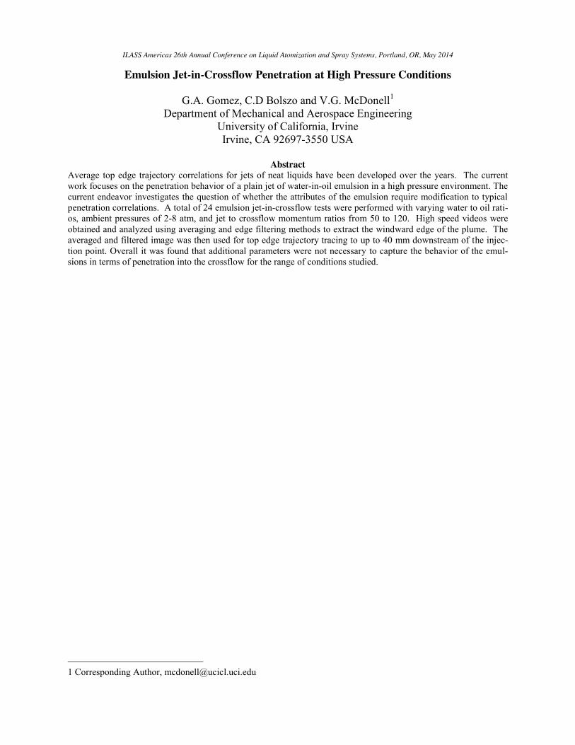
While various correlations from Ingebo, Chelko, and Inamura have been developed for maximum pene-tration, these were all developed for 10 diameters downstream of the nozzle exit, which lacks information regarding the near-field structure and breakup process. Results from Reichenbach and Horn found that jet tra-jectories were insensitive to liquid property variations and could be solely correlated using a momentum flux ratio average (Reichenbach, 1971). Similarly Nejad and Schetz found that surface tension was negligible for penetration heights but that jets with smaller surface tension had a faster jet disintegration process and pro-duced smaller droplets (Nejad & Schetz, 1984). The formation of spherical droplets in an airflow is due to aerodynamic forces acting on the fluid (Wu, Kirkendall, & Fuller, 1997). In the work of Wu et al. liquid jets from a tapered nozzle were injected vertically and per-pendicular to a subsonic crossflow and a frequency-doubled YAG laser was used to freeze the motion of the liquid column and droplets providing shadowgraphs of the spray. The liquid composition, nozzle diameters, injection velocities and air velocities were varied in (Wu, Kirkendall, & Fuller, 1997). These shadowgraphs allowed for the characterization of the near field liquid breakup regimes in an air crossflow as presented in Figure 1.
Figure 1 Schematic of jet-in-crossflow near field liquid jet break up (Wu, Kirkendall, & Fuller, 1997)
Penetration correlations have been developed by various authors, generally specific to a momentum flux ratio range. The equation framework in equation 2 for penetration heights includes momentum flux ratio q, nozzle diameter d, and downstream distance x in order to predict the penetration height y. This equation was developed for a q range of 5-50 (Wu P. K., 1998). Equation 3 is a modification of equation 2 by Hassa et al. for elevated pressure conditions and a q range of 1-40 (Rachner, 2002). Equation 4 by Stenzler et al. took the aerodynamic Weber number into consideration in addition to fluid viscosity of the fuel in comparison to water (Stenzler, 2003). Equation 5 by Birourk et al. is similar to Equ 4 but does not take Weber number into account (Birouk, 2007). Equation 6 produced by Lee et al. was developed for a large q range of 3-200 takes into consideration the discharge coefficient. Since equation 6 has such a large range of momentum flux ratio it may be useful for applicable gas turbine conditions.
2 𝑦𝑑 = 𝑎𝑞 𝑥
𝑑
3
𝑦𝑑 = 𝑎𝑞 𝑙𝑛 1 + 𝑐 𝑥
𝑑
4 𝑦𝑑 = 𝑎𝑞 𝑥
𝑑 𝑊𝑒 𝜇𝜇
5 𝑦𝑑 = 𝑎𝑞 𝑥
𝑑𝜇𝜇
6
𝑦𝑑𝑞 =
𝜋𝐶
𝑥𝑑𝑞
A review of literature on jet-in-crossflow and wa-
ter-in-oil emulsions demonstrates their advantages in gas turbine fuel injection technology from both a pollu-tion control and engine efficiency standpoint. From a pollution control standpoint, the use of an emulsion can allow for a reduction in NOx, CO, and unburned hydro-carbons by improved temperature control and fuel at-omization within the gas turbine. From an efficiency standpoint the jet-in-crossflow injection strategy allows for the utilization of combustion chamber air to break down and atomize liquid fuel saving energy cost of increasing the liquid injection pressure. Previous re-
search on water-in-oil emulsions also highlights im-provements in fuel atomization with the use of emul-sions due to flow instabilities that result from water in oil interaction in the flow in addition to improved atom-ization from the phenomenon of microexplosions.
To the author’s knowledge, no research on emul-sion jet-in-crossflow at elevated pressure conditions has been carried out. Elevated pressures result in an in-crease in ambient pressure density which increases the aerodynamic Weber number. Previous research on jet-in-crossflow highlights the relationship between Weber number, momentum flux ratio, and jet-in-crossflow break up regimes. Recent work by Bolszo et al. (2014) on emulsion jets-in-crossflow at atmospheric conditions identified momentum flux ratio being the only statisti-cally significant driver for penetration regardless of emulsion quality or oil to water ratio. In the present work, data are obtained at elevated pressure conditions to explore the generality of this finding.
Objective and Approach
The objective of the present work is to understand the impact of water-in-oil emulsions on the top edge trajectory of a jet-in-crossflow. To accomplish this ob-jective, high speed imaging diagnostics are applied to emulsion jet-in-crossflows.
Experiment
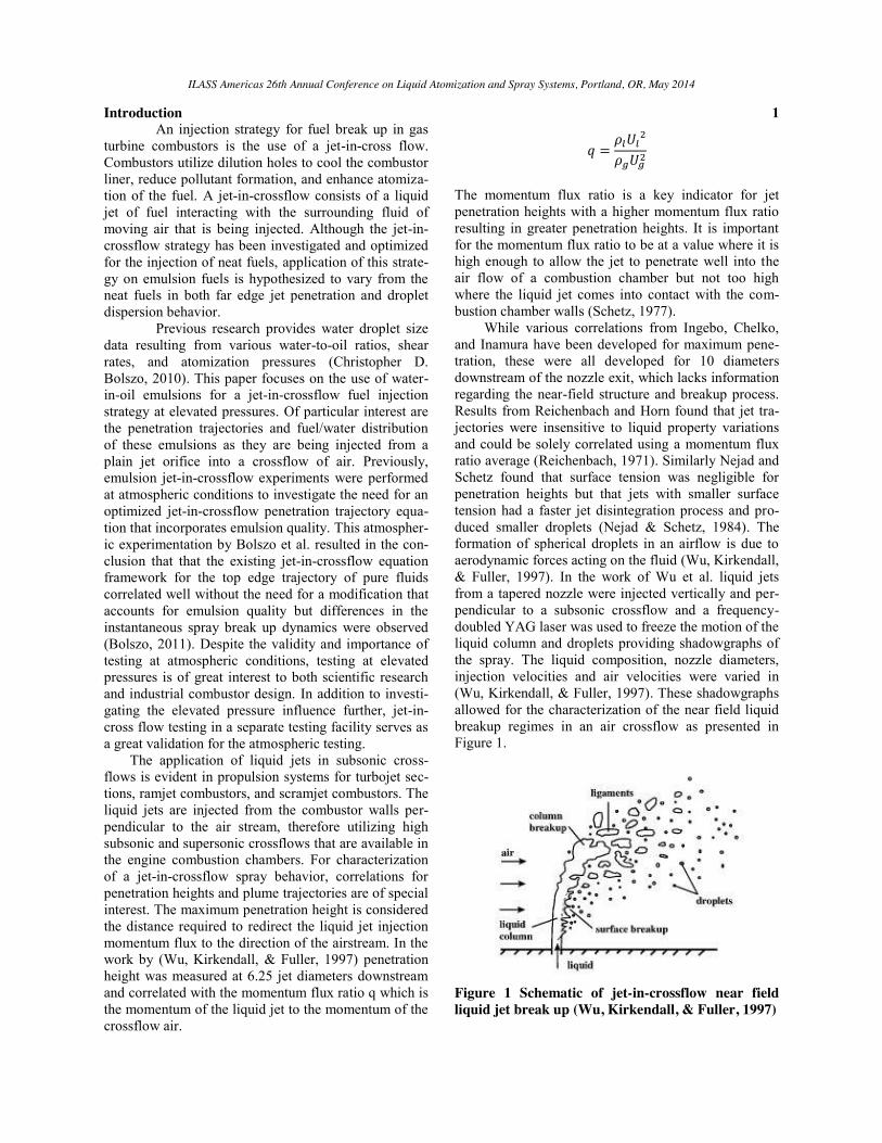
The facility used to carry out the tests is that de-scribed in detail in Leong, et al. (2001). Additional liquid handling capability was added to allow the injec-tion of emulsions. Figure 2 illustrates the installation of the test section into the pressure vessel.
Figure 2 Installation of Test Section within 457 mm i.d. pressure vessel
A Phantom v7.1 (Vision Research) digital high speed camera is used with a 7 µs exposure time and with 100 µs interval at 1,400 frames per second (fps). Attaching a long distance microscopic lens (Infinity Model K2/SC) onto the high speed camera allowed for
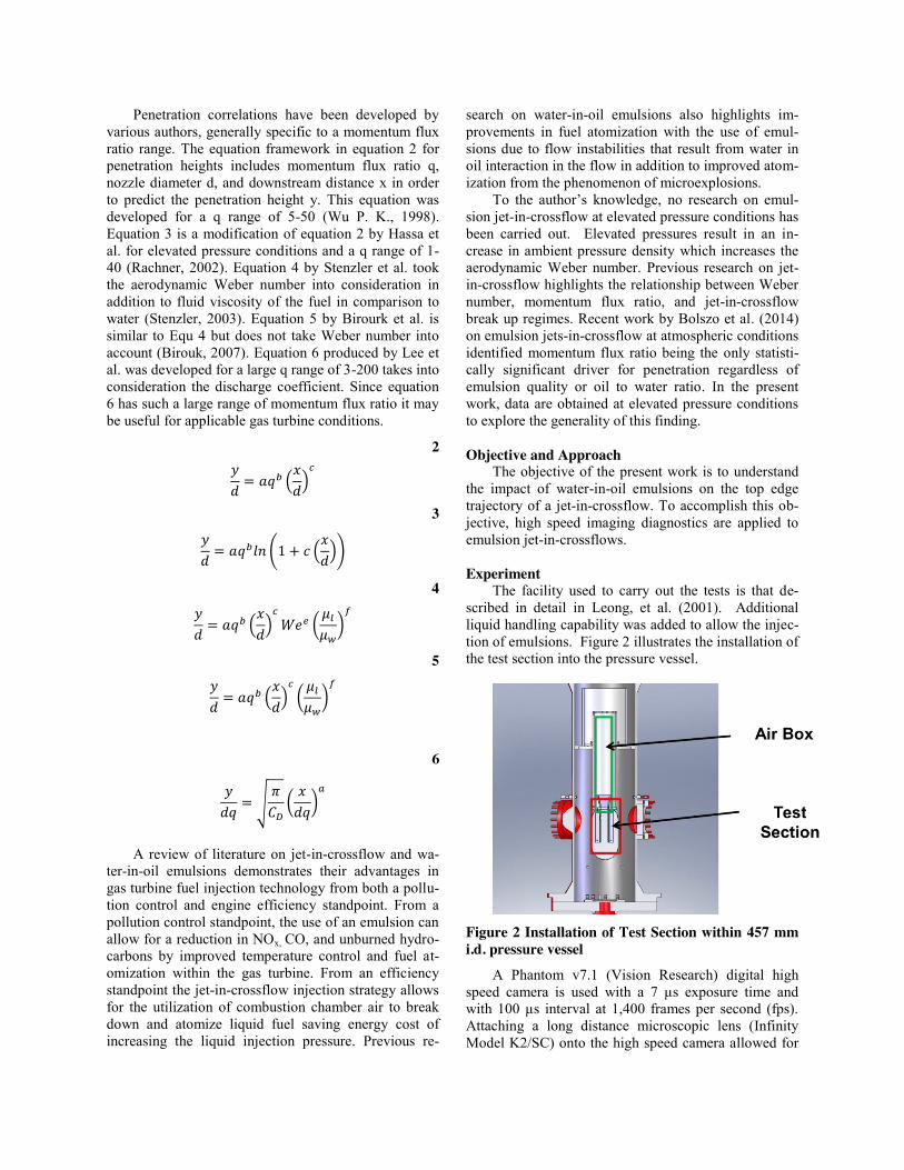
a well-focused video of the spray plume from the injec-tion point to 40 mm downstream. One of the challenges associated with the installation of the camera was ob-taining clear images through the front window of the test rig displayed in Figure 3. A back light was installed on the opposite window to provide enough lumines-cence for the high speed capture of spray frames in the videos. Lighting required care in order to provide suffi-cient intensity while maintaining a relatively uniform intensity. A diffuser was used in front of the back light to help with maintaining this uniform intensity. Another issue associated with the experimental set up was win-dow wetting on the front window. An air knife was installed parallel to the window to prevent the settling of droplets on the window, but at higher pressures the air knife lost its effectiveness due to the limited back pressure of the air feeding the air knife. When the win-dow was maintained clear throughout testing, the result-ing results could be processed using computer aided image analysis of the high speed videos.
Figure 3 High speed cinematography set up for high pressure facility
Liquids used to generate unstable water-in-oil emulsions for experimentation include filtered water and low sulfur diesel distillate fuel #2 (DF2). Table 1 lists these liquids with some of their corresponding flu-id properties.
Table 1 Table of liquids used with properties based on atmospheric conditions
Water Diesel Fuel
Chemical Formula H2O C10-14H20-28 Density, kg/m3 1012 825 Viscosity, kg/m-s 1.37E-03 2.93E-03 Surface Tension, kg/s2 0.0693 0.0280
Emulsion fluid properties have also been
previously measured at the UCICL (UCI Combustion Laboratory) using a graduated cylinder, electronic mas scale, falling ball viscometer for viscosity measurements, a stalagmometer for surface tension measurements, and the pendant drop method for
interfacial tension. Surfactants were utilized to stabilize the emulsions and make these measurements possible. The table below depicts these measurements emulsion property characterization.
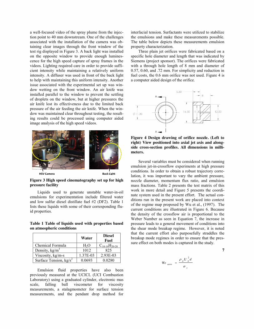
Three plain jet orifices were fabricated based on a specific hole diameter and length that was indicated by Siemens (project sponsor). The orifices were fabricated with a through hole length of 8 mm and diameter of 0.57, 0.60, and .72 mm. For simplicity and reduction in fuel costs, the 0.6 mm orifice was not used. Figure 4 is a computer aided design of the orifice.
Figure 4 Design drawing of orifice nozzle. (Left to right) View positioned into axial jet axis and along-side cross-section profiles. All dimensions in milli-meters.
Several variables must be considered when running
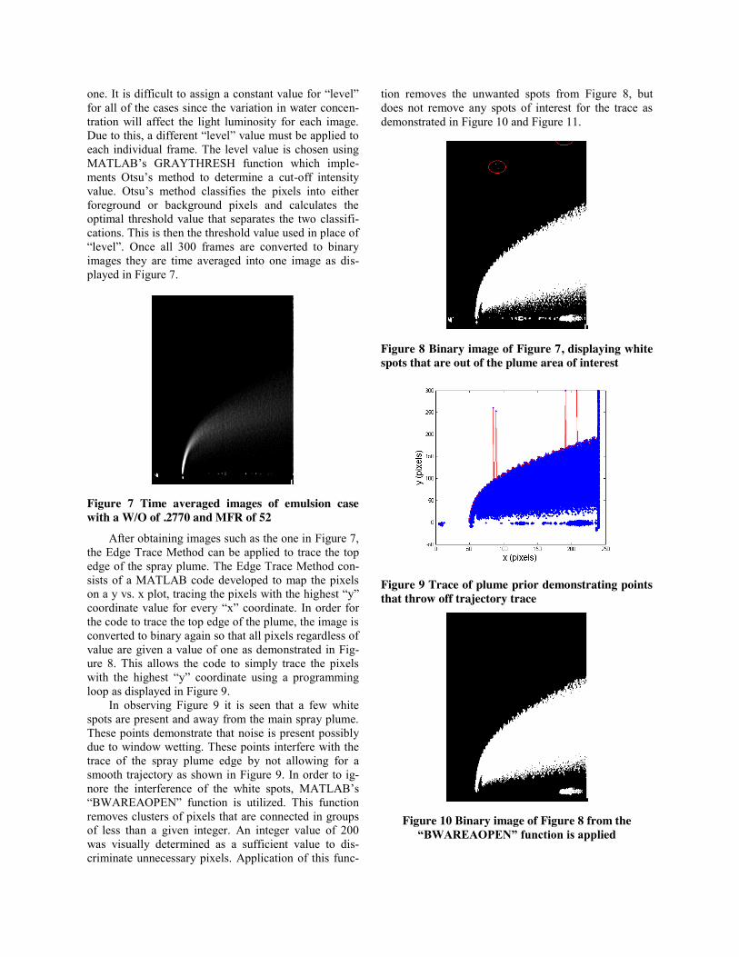
emulsion jet-in-crossflow experiments at high pressure conditions. In order to obtain a robust trajectory corre-lation, it was important to vary the ambient pressure, nozzle diameter, momentum flux ratio, and emulsion mass fractions. Table 2 presents the test matrix of this work in more detail and Figure 5 presents the coordi-nate system used in the present effort. The actual con-ditions run in the present work are placed into context of the regime map proposed by Wu et al., (1997). The current conditions are illustrated in Figure 6. Because the density of the crossflow air is proportional to the Weber Number as seen in Equation 7, the increase in pressure leads to a general movement of conditions into the shear mode breakup regime. However, it is noted that the current effort also purposefully straddles the breakup mode regimes in order to ensure that the pres-sure effect on both modes is captured in the study.
7
s
ggaero
dUWe
V
U 2
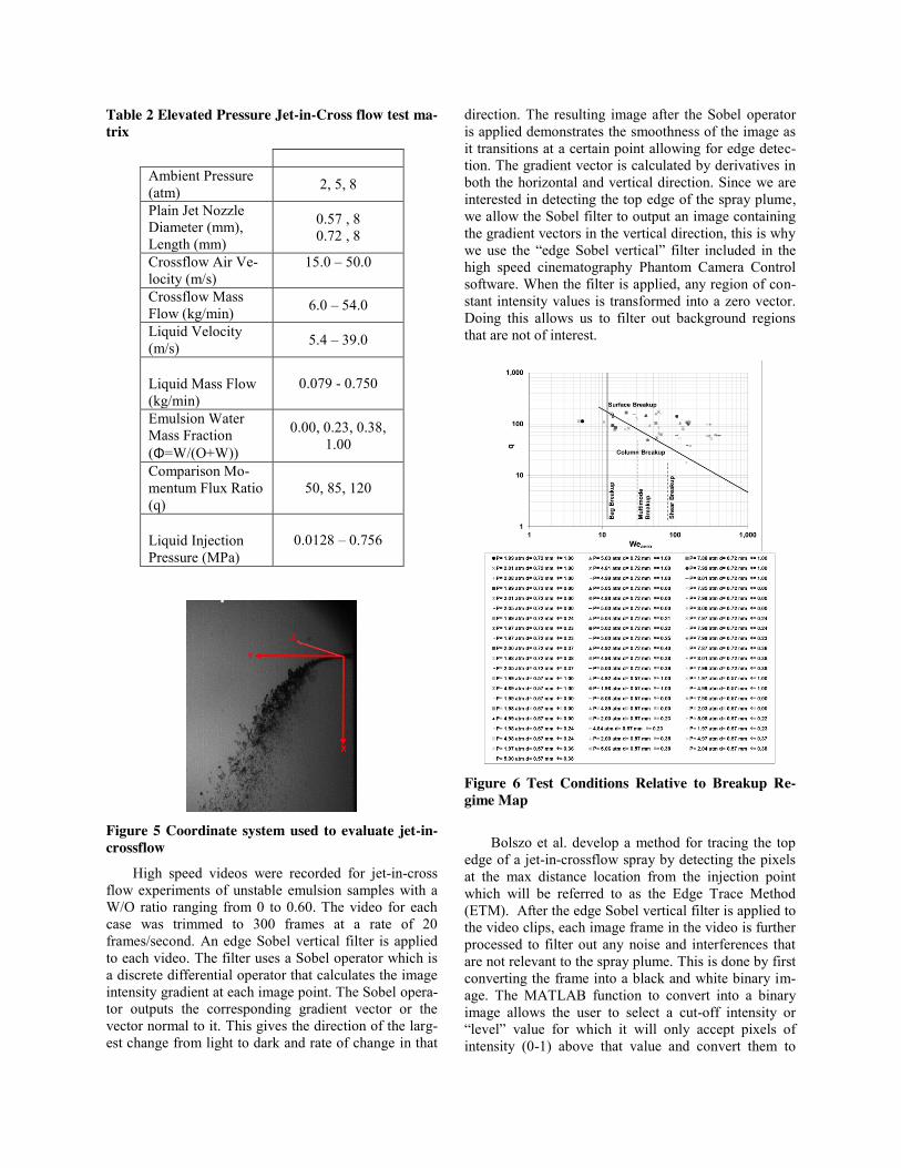
Table 2 Elevated Pressure Jet-in-Cross flow test ma-trix
Ambient Pressure (atm) 2, 5, 8
Plain Jet Nozzle Diameter (mm), Length (mm)
0.57 , 8 0.72 , 8
Crossflow Air Ve-locity (m/s)
15.0 – 50.0
Crossflow Mass Flow (kg/min) 6.0 – 54.0
Liquid Velocity (m/s) 5.4 – 39.0
Liquid Mass Flow (kg/min)
0.079 - 0.750
Emulsion Water Mass Fraction (Φ=W/(O+W))
0.00, 0.23, 0.38, 1.00
Comparison Mo-mentum Flux Ratio (q)
50, 85, 120
Liquid Injection Pressure (MPa)
0.0128 – 0.756
Figure 5 Coordinate system used to evaluate jet-in-crossflow
High speed videos were recorded for jet-in-cross flow experiments of unstable emulsion samples with a W/O ratio ranging from 0 to 0.60. The video for each case was trimmed to 300 frames at a rate of 20 frames/second. An edge Sobel vertical filter is applied to each video. The filter uses a Sobel operator which is a discrete differential operator that calculates the image intensity gradient at each image point. The Sobel opera-tor outputs the corresponding gradient vector or the vector normal to it. This gives the direction of the larg-est change from light to dark and rate of change in that
direction. The resulting image after the Sobel operator is applied demonstrates the smoothness of the image as it transitions at a certain point allowing for edge detec-tion. The gradient vector is calculated by derivatives in both the horizontal and vertical direction. Since we are interested in detecting the top edge of the spray plume, we allow the Sobel filter to output an image containing the gradient vectors in the vertical direction, this is why we use the “edge Sobel vertical” filter included in the high speed cinematography Phantom Camera Control software. When the filter is applied, any region of con-stant intensity values is transformed into a zero vector. Doing this allows us to filter out background regions that are not of interest.
Figure 6 Test Conditions Relative to Breakup Re-gime Map
Bolszo et al. develop a method for tracing the top
edge of a jet-in-crossflow spray by detecting the pixels at the max distance location from the injection point which will be referred to as the Edge Trace Method (ETM). After the edge Sobel vertical filter is applied to the video clips, each image frame in the video is further processed to filter out any noise and interferences that are not relevant to the spray plume. This is done by first converting the frame into a black and white binary im-age. The MATLAB function to convert into a binary image allows the user to select a cut-off intensity or “level” value for which it will only accept pixels of intensity (0-1) above that value and convert them to
one. It is difficult to assign a constant value for “level” for all of the cases since the variation in water concen-tration will affect the light luminosity for each image. Due to this, a different “level” value must be applied to each individual frame. The level value is chosen using MATLAB’s GRAYTHRESH function which imple-ments Otsu’s method to determine a cut-off intensity value. Otsu’s method classifies the pixels into either foreground or background pixels and calculates the optimal threshold value that separates the two classifi-cations. This is then the threshold value used in place of “level”. Once all 300 frames are converted to binary images they are time averaged into one image as dis-played in Figure 7.
Figure 7 Time averaged images of emulsion case with a W/O of .2770 and MFR of 52
After obtaining images such as the one in Figure 7, the Edge Trace Method can be applied to trace the top edge of the spray plume. The Edge Trace Method con-sists of a MATLAB code developed to map the pixels on a y vs. x plot, tracing the pixels with the highest “y” coordinate value for every “x” coordinate. In order for the code to trace the top edge of the plume, the image is converted to binary again so that all pixels regardless of value are given a value of one as demonstrated in Fig-ure 8. This allows the code to simply trace the pixels with the highest “y” coordinate using a programming loop as displayed in Figure 9.
In observing Figure 9 it is seen that a few white spots are present and away from the main spray plume. These points demonstrate that noise is present possibly due to window wetting. These points interfere with the trace of the spray plume edge by not allowing for a smooth trajectory as shown in Figure 9. In order to ig-nore the interference of the white spots, MATLAB’s “BWAREAOPEN” function is utilized. This function removes clusters of pixels that are connected in groups of less than a given integer. An integer value of 200 was visually determined as a sufficient value to dis-criminate unnecessary pixels. Application of this func-
tion removes the unwanted spots from Figure 8, but does not remove any spots of interest for the trace as demonstrated in Figure 10 and Figure 11.
Figure 8 Binary image of Figure 7, displaying white spots that are out of the plume area of interest
Figure 9 Trace of plume prior demonstrating points that throw off trajectory trace
Figure 10 Binary image of Figure 8 from the “BWAREAOPEN” function is applied
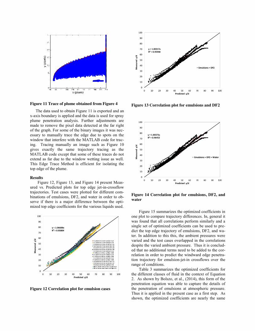
Figure 11 Trace of plume obtained from Figure 4
The data used to obtain Figure 11 is exported and an x-axis boundary is applied and the data is used for spray plume penetration analysis. Further adjustments are made to remove the pixel data detected at the far right of the graph. For some of the binary images it was nec-essary to manually trace the edge due to spots on the window that interfere with the MATLAB code for trac-ing. Tracing manually an image such as Figure 10 gives exactly the same trajectory tracing as the MATLAB code except that some of these traces do not extend as far due to the window wetting issue as well. This Edge Trace Method is efficient for isolating the top edge of the plume.
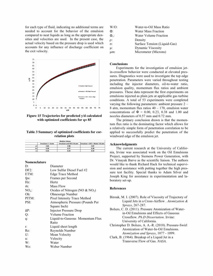
Results Figure 12, Figure 13, and Figure 14 present Meas-
ured vs. Predicted plots for top edge jet-in-crossflow trajectories. Test cases were plotted for different com-binations of emulsions, DF2, and water in order to ob-serve if there is a major difference between the opti-mized top edge coefficients for the various liquids used.
Figure 12 Correlation plot for emulsion cases
Figure 13 Correlation plot for emulsions and DF2
Figure 14 Correlation plot for emulsions, DF2, and water
Figure 15 summarizes the optimized coefficients in
one plot to compare trajectory differences. In, general it was found that all correlations perform similarly and a single set of optimized coefficients can be used to pre-dict the top edge trajectory of emulsions, DF2, and wa-ter. In addition to this this, the ambient pressures were varied and the test cases overlapped in the correlations despite the varied ambient pressure. Thus it is conclud-ed that no additional terms need to be added to the cor-relation in order to predict the windward edge penetra-tion trajectory for emulsion-jet-in crossflows over the range of conditions.
Table 3 summarizes the optimized coefficients for the different classes of fluid in the context of Equation 2. As shown by Bolszo, et al., (2014), this form of the penetration equation was able to capture the details of the penetration of emulsions at atmospheric pressure. Thus it is applied in the present case as a first step. As shown, the optimized coefficients are nearly the same
for each type of fluid, indicating no additional terms are needed to account for the behavior of the emulsion compared to neat liquids as long as the appropriate den-sities and velocities are used. In the present case, the actual velocity based on the pressure drop is used which accounts for any influence of discharge coefficient on the exit velocity.
Figure 15 Trajectories for predicted y/d calculated
with optimized coefficients for q= 85
Table 3 Summary of optimized coefficients for cor-relation plots
Nomenclature D: Diameter DF2: Low Sulfur Diesel Fuel #2 ETM: Edge Trace Method fps: Frames per Second Hz: Hertz �̇�: Mass Flow NOx: Oxides of Nitrogen (NO & NO2) Oh: Ohnesorge Number PITM: Pixel Intensity Trace Method PSI: Atmospheric Pressure (Pounds Per
Square Inch) ΔP: Injector Pressure Drop Q: Volume Fraction q: Liquid-to-Gaseous Momentum Flux
Ratio r: Liquid sheet length Re: Reynolds Number U: Mean Velocity u: Velocity W: Water We: Weber Number
W/O: Water-to-Oil Mass Ratio Φ: Water Mass Fraction Φv: Water Volume Fraction U: Density σ: Surface Tension (Liquid-Gas) μ: Dynamic Viscosity μm: Micrometer (Microns) Conclusions
Experiments for the investigation of emulsion jet-in-crossflow behavior were conducted at elevated pres-sures. Diagnostics were used to investigate the top edge penetration. Parameters were varied throughout testing including the injector diameters, oil-to-water ratio, emulsion quality, momentum flux ratios and ambient pressures. These data represent the first experiments on emulsions injected as plain jets at applicable gas turbine conditions. A total of 53 experiments were completed varying the following parameters: ambient pressure 2 – 8 atm, momentum flux ratios 40 – 170, emulsion water concentrations of Φ = 0.00, 0.23, 0.38 and 1.00 and nozzles diameters of 0.57 mm and 0.72 mm.
The primary conclusion drawn is that the momen-tum flux ratio is the dominating factor which allows for a relatively simple form of penetration correlation to be applied to successfully predict the penetration of the windward edge of the emulsion jet.
Acknowledgments
The current research at the University of Califor-nia, Irvine was associated work on the Oil Emulsions Project, supported by Siemens Power Generation, with Dr. Vinayak Barve as the scientific liaison. The authors would like to thank Richard Hack for technical supervi-sion and assistance with putting together the high pres-sure test facility. Special thanks to Adam Silver and Joseph King for assistance in experimentation and la-boratory set-up. References
Birouk, M. I. (2007). Role of Viscosity of Trajectory of
Liquid Jets in a Cross-Airflow . Atomization & Sprays, 267-287.
Bolszo, C. D. (2011). Pressure Atomization of Water-in-Oil Emulsions and Effects of Gaseous Crossflow. Ph.D Dissertation. Irvine: University of California.
Christopher D. Bolszo, A. A.-R. (2010). Pressure-Swirl Atomization of Water-In-Oil Emulsions. Atomization and Sprays, 1077 - 1099.
Clark, B. (1964). Breakup of a Liquid Jet in a Transverse Flow of Gas. NASA.
Emulsion 2 - 8 atm Emulsion and DF2 2-8 atm Emulsion + DF2 + Water 2-8 atm
a= 2.83 2.98 2.87
b= 0.38 0.37 0.38
c= 0.35 0.34 0.34
Median Values
Nejad, A., & Schetz, J. (1984). Effects of Viscosity and Surface Tension on a Jet Plume in Supersonic Crossflow. AIAA Journal, Vol 22, No.4, 653-659.
Rachner, M. B. (2002). Modeling of the atomization of a plain liquid fuel jet in crossflow at gas turbine conditions. Aerospace Science & Technology, 495-506.
Reichenbach, R. a. (1971). Investigation of Injectant Properties on Jet Penetration in a Supersonic Stream. AIAA Journal, Vol. 9, 469-472.
Schetz, J. P. (1977). Penetration and Breakup of Liquids in Subsonic Airstream. AIAA Journal, 774-778.
Stenzler, J. L. (2003). Penetration of Liquid Jets in a Crossflow. Aerospace Sciences Meeting & Exhibit.
Wu, P. K. (1998). Spray structure of liquid jets atomized in subsonic crossflows. Propulsion and Power, 173-182.
Wu, P.-K., Kirkendall, K. A., & Fuller, R. P. (1997). Breakup Processes of Liquid Jets in Subsonic Crossflow. Journal of Propulsion and Power, 64-73.