Emtek P100 Portable Microbial Air Sampler Manual · 2019-06-19 · 6 2.5 P100 Technical Description...
64
1 P100 Portable Microbial Air Sampler Users Manual Contact Us for Customer Service and Technical Support EMTEK, LLC 1500 Kansas Ave., Suite 3-F Longmont, CO 80501 Website: http://www.emtekair.com Phone: 877.850.4244 Email: [email protected] Fax: 303.223.2804
Transcript of Emtek P100 Portable Microbial Air Sampler Manual · 2019-06-19 · 6 2.5 P100 Technical Description...
1
P100 Portable Microbial Air Sampler
Users Manual
Contact Us for Customer Service and Technical Support
EMTEK, LLC
1500 Kansas Ave., Suite 3-F
Longmont, CO 80501
Website: http://www.emtekair.com
Phone: 877.850.4244
Email: [email protected]
Fax: 303.223.2804
2
Table of Contents Section 1 Specifications ......................................................................................................................................... 4 Section 2 General Information ............................................................................................................................. 5
2.1 Document Description ................................................................................................... 5 2.2 Copyright ....................................................................................................................... 5 2.3 Disclaimer ..................................................................................................................... 5 2.4 License Restriction ........................................................................................................ 5 2.5 P100 Technical Description .......................................................................................... 6 2.6 Safety Notices ............................................................................................................... 8 2.6.1 Referenced Hazard Information ........................................................................ 8 2.6.2 Precautionary Labels .......................................................................................... 9 2.7 Standards and Regulation ............................................................................................. 11 2.7.1 CE Declaration of Conformity ........................................................................ 11 2.7.2 21 CFR Part 11 Compliance ............................................................................ 11 2.8 Warranty ....................................................................................................................... 11 2.9 Calibration ...................................................................................................................... 11
Section 3 Product Introduction……………………………………………………………………………….…...12
3.1 Feature Summary ........................................................................................................ 12 3.2 Unpacking or Packing ................................................................................................. 13 3.2.1 Component Checklist ...................................................................................... 13 3.2.2 Optional Accessories ....................................................................................... 14
Section 4 Installation………….…………………………………………………..…………………………...…...15
4.1 Wiring Safety Information ............................................................................................ 15 4.2 Electrostatic Discharge (ESD) Considerations ........................................................... 15 4.3 Electrical & Data Connections .................................................................................... 17
Section 5 P100 Description .................................................................................................................................. 18
5.1 P100 Front View ......................................................................................................... 18 5.2 P100 Rear View .......................................................................................................... 19
Section 6 Quick Start Guide ............................................................................................................................... 20 Section 7 Operating Instructions ........................................................................................................................ 21
7.1 Touch Screen Description and Function ..................................................................... 21 7.1.1 Setup Screen (Main Menu) ........................................................................... 21 7.1.2 Run Display. .................................................................................................. 23 7.1.3 Set Sample Parameters .................................................................................. 24 7.1.4 Printer ............................................................................................................ 25 7.1.5 Alarm (Flow) & IR Remote Settings ............................................................ 26 7.1.6 Delay, Test, & Hold Settings ......................................................................... 27 7.1.7 Site Descriptions ............................................................................................ 28

3
7.1.8 Date & Time Settings .................................................................................... 29 7.1.9 Data Output (Printer & USB) ........................................................................ 30 7.1.10 Calibration (Due & Notification) ................................................................... 32 7.1.11 Administrative (Admin & User) .................................................................... 33 7.1.11.1 Administrative Control Options ....................................................... 35 7.1.12 Unit Information (Firmware Version) ........................................................... 37 7.1.13 Save (Sample) Programs (Select, Add, Delete) ............................................. 38 7.2 Using the Keypad Function to Enter Site/Sample Descriptions ................................. 40 7.3 IR Remote Control ...................................................................................................... 43 7.3.1 Loading the Batteries into the Remote Control ............................................... 43 7.3.2 Operating the P100 with the Remote Control .................................................. 44 7.4 Alarms/ Warning Screens ............................................................................................ 44 7.5 Optional Thermal Printer Operation ........................................................................... 45 7.6 HEPA Filter & Battery Pack ....................................................................................... 48 7.7 Touch Screen Sensor Calibration ................................................................................ 48 7.8 Transporting the P100 Sampler ................................................................................... 48
Section 8 Network Operation of the P100 ......................................................................................................... 49
Appendix A P100 Sampler - General Sampling Procedure ................................................................................. 50
A.1 P100 Operating Principles ........................................................................................... 50 A.2 Materials ...................................................................................................................... 51 A.3 Maintenance Inspection ............................................................................................... 51 A.4 P100 Sampler Assembly Set-Up and Testing ............................................................. 52 A.5 Storage and Transport ................................................................................................. 57
Appendix B Suggested P100 Sampler Sanitation ................................................................................................ 58
B.1 Materials ...................................................................................................................... 58 B.2 Sanitization Procedure ................................................................................................. 58
Appendix C Suggested Sample Submission and Results Recording ................................................................. 61
Feller Calculation Tables………………………………………………………………...…...62 Appendix 1 CE Declaration of Conformity ......................................................................................................... 63 Appendix 2 Warranty ............................................................................................................................................ 64

4
Section 1 Specifications
P100 Air Sampler Controller Motor Type Blower Motor
Display/Interface Two Color LCD with Touch Screen (Blue on White), CPU
Current Firmware Version 1.071
Sample Time/Volume Variable (User Defined), Maximums: 120-minutes/3396 Liters* @ 28.3 LPM, 30-min/3000L @ 100 LPM
Delay/Hold Times Variable (User Defined)
Sample Flow Rates 28.3 or 100 liters per minute (LPM), or 1 cubic feet per minute (CFM)
NOTE: Requires separate inlet covers for the 28.3 (1 CFM) and 100 LPM Sample Rates
Flow Rate Control Electronic, Closed-Loop, Mass-Flow Control
Printer (Optional) Thermal Label or Paper
Control System (CPU) Microprocessor Controlled (32bit PIC Processor)
Memory 512kb Flash Program , 128kb RAM Data, 1mb Sample Runs, 512kb EPROM Calibration Set Points
Unit Equipment ID/Number User Defined/Selectable
Site Descriptions User Created/Deleted/Selectable
Program Descriptions User Created/Deleted/Selectable (Includes: Sample Rate, Volume/Time, Flow/Volume Units, Delay/Test/Hold)
Sample ID Unique System Generated (Unit Serial # + 5 digit string)
Input/Output USB Client 1.1, Ethernet 10BaseT-/100-BaseT
Audible Alarm Internal (with User Volume Control)
Alarms Flow Alarm +5% (On/Off)
Dimensions LxWxH: 7.5 x 5.5 x 6.5 inches (190 x 134 x x 165 cm)
Enclosure Materials Inlet Base & Base Cover: 6061 Aluminum (Clear Anodized) / Cover: KydexTM with MicrobanTM / Handle: Aluminum
Inlet Cover Materials 6061 Aluminum, 28.3 LPM (1 CFM) Inlet Clear Anodized, 100 LPM Inlet Blue Anodized, 300 Holes/Inlet Cover
Exhaust Filter HEPA Filter, 0.2 micron, Replaceable
Weight 5.4 Pounds 2.5 Kilograms
Tripod Mount Bottom Cover, ¼-20 Threading x 0.250” (6.4 mm) Depth
Battery Pack 8 Cell Lithium Ion, 4400mAh, 14.8V
AC/DC Power Supply Input: 100-240 VAC, 50/60 Hz,130VA-168VA 1.4 AMPS / Output: DC 18V 3.6A
Battery Charging/Life Full Battery Charge from Full Discharge: Approximately 2.5 hours
Battery Life: Approximately 12 Hours @ 28.3 LPM & 6 Hours @ 100 LPM
Operating Range 5-40º C, 10-80% RH, non-condensing*; Indoor Use; Max Altitude 6560 feet (2000 meters)
*Note: As temperature increases from 30 to 40º C, humidity range drops from 80 to 50% linearly.
Calibration Flow Rate (28.3/1 CFM and/or100 LPM)
Calibration Frequency User Defined (Recommended every 6-12 months)
Verification Sample Timer
Verification Frequency User Defined (Recommended every 6-12 months)
Gas Compatibility Air and inert gases such as carbon dioxide, nitrogen, and argon
Installation Category Category 1
Pollution Degree 1 and 2
5
Section 2 General Information
2.1 Document Description
Document EMTEK.P100.001v01 (First Edition). October 2013. This document remains the official reference source for all revisions/releases of this product until rescinded by an update, including current and updated versions of the operating firmware and software.
2.2 Copyright
© 2013 by EMTEK, LLC. All rights reserved.
2.3 Disclaimer
It is the policy of EMTEK, LLC to improve this manual and the products it describes as new technology, components, software, and firmware become available. EMTEK, LLC reserves the right to make changes to any products herein at any time without notice. In some instances, photographs and figures are of equipment prototypes. Therefore, before using this document, consult your EMTEK, LLC representative for information that is applicable and current. The information in this manual is believed to be accurate. However, EMTEK, LLC assumes no responsibility for any inaccuracies that may be contained in this manual. In no event will EMTEK, LLC be liable for direct, indirect, special, incidental, or consequential damages resulting from any defect or omission in this manual, even if advised of the possibility of such damages. In the interest of continued product development, EMTEK, LLC reserves the right to make improvements in this manual and the products it describes at any time, without notice or obligation. No part of the contents of this manual may be reproduced or transmitted in any form or by any means without the written permission of EMTEK, LLC.
2.4 License Restriction
The purchase or use of an EMTEK, LLC product does not convey a license under any patent, copyright, trademark, or other intellectual property right of EMTEK, LLC or third parties.
6
2.5 P100 Technical Description
The P100 (EMTEK, LLC Portable 100) is a portable, battery operated, microbial air sampler. Its enclosure is comprised of a top cover that is made of KydexTM that lies over an aircraft grade aluminum base plate. The KydexTM cover contains MicrobanTM, an antimicrobial agent that minimizes and/or reduces the growth of microbial contaminants that may come in contact with the KydexTM cover. The user interfaces with the P100 through a two color LCD touch screen for entering user defined sample parameters and for the initiation and termination of sample runs. During operation the LCD displays key sample run information, as well as a visual sample progress indicator. The P100 is offered with two (2) sample flow rates: 28.3 LPM (1 CFM) and 100 LPM. The highest flow rate, 100 LPM, allows for the collection of a cubic meter of air in 10-minutes, while the 28.3 LPM (1 CFM) flow rate takes approximately 35 minutes to capture a cubic meter. The flow is controlled through a proprietary CPU control system, which offers automated flow control of the two defined flow rates. Flow rates are calibrated and set against traceable standards through the use of an external software program and may not be altered through the user interface on the unit. Sample rates and total volume sampled maybe displayed and output in Cubic Feet, Liters, or Cubic Meters (only for total volume). Flow alarm settings are available for the flow rates, which will produce both an audible and visual alarm during operation and may be output to the optional printer upon completion/termination of the sample period. Alarm occurrences are maintained within the systems internal memory with the associated sample parameter information until the 500 sample run memory buffer is cleared. The P100 operates with separate sieve impaction inlet covers for each of the two flow rates, 28.3 LPM (1 CFM) and 100 LPM. The inlet covers include a 300 hole pattern with appropriate inlet hole sizing for each flow rate to assure optimal physical and biological recovery capabilities. Each inlet cover includes a distance gauge, which works in conjunction an adjustable media stage to assure an ideal distance is maintained between the inlet cover and test media surface for appropriate microbial particulate capture. The air sampler uses standard 90mm agar based microbial test plates (e.g., Trypticase Soy Agar (TSA)). During testing the sampled air volume drawn through each air sampler is HEPA filtered before being exhausted within the P100. The P100 software, allows for sampling periods of up to 120-minutes (or 120 Cubic Feet/3396 Liters/3.4 Cubic Meters) at the 28.3 LPM sample rate, while sample times are limited 30-minutes (or 106 Cubic Feet/3000 Liters/3 Cubic Meters) at 100 LPM. While the stated time periods, or total sample volumes are allowed by the P100, EMTEK strongly suggests that all sampling periods employed by be qualified by the user to verify appropriate organismal recovery. In addition, the P100 offers the user the capability of entering an initial sample delay, as well as hold and test periods for each sample run. This initial sample delay allows the user time to exit the immediate area of the sample location, while the hold and test period settings allows for intermittent sampling of an area or process for an extended time period, as determine appropriate by the user. For an example, the user may set an initial delay period of 3-minutes and then opt to sample for 5-minute periods with 5-minute hold periods between each 5-minute sampling period, which will occur for a period up to the maximum total sampling period defined for the flow rate chosen. If the flow rate chosen is 28.3 LPM, and the maximum active sampling period set is 60-minutes, this would allow for twelve (12) 5-minute test periods, followed by eleven (11) 5-minute hold periods, for a total plate exposure time of 118-minutes (including the 3-minute initial delay). This would result in a total of 60-minutes of active sampling. The blower motor powers down during hold periods. Again, EMTEK recommends the user qualify any sampling plan used, to include sample delay, and test/hold periods.
7
The P100 maintains key sample run parameter data within its internal memory, which is maintained until the memory buffer is cleared by the user or unit administrator, and/or if the 500 sample run memory buffer capacity is exceeded. Based on administrative options, the unit will either allow no more runs to be taken with the unit until the run data is reviewed and cleared, or it will remove the oldest run stored with each new run take. The data maintained in the system includes set/actual flow rate, set/actual sample volume, sample start/end times, set delay, test and hold period, equipment and serial numbers, calibration date and due date of the controller/air sampler(s), user defined site description, user ID, and alarms during sampling. An alphanumeric keypad is provided on the touch screen for entering user defined site identifiers/descriptions. All sample runs are date and time stamped and are also assigned a unique sample identification string which is comprised of the units assigned serial number and a non-repeating character string up to 99,999 samples. The run data cannot be altered within the CPU system of the P100. It may only be output (via USB Stick, or Printer), viewed (via LCD, or PC), or cleared from the system. Sample runs on the P100 can be initiated through either the P100 touch screen Run Display screen, the supplied Infrared Remote (IR Remote), or by remote PC operation (optional). Using either the P100 display, IR Remote, or PC (optional), the user can START, PAUSE, RESUME, or STOP a sampling session. The IR Remote allows for these functions at a distance of up to 40-Feet, or approximately 12 meters, with line of site to the P100 IR Receiver window located just above the touch screen display on the P100. The supplied single IR remote can operate up to 5 P100’s with different IR ID#’s set on the unit (user selectable IR ID#’s 1 through 5). There are several options available for the P100. This includes a handheld thermal printer, Remote PC/Ethernet based operation, horizontal flow inlet, compressed air/gas testing kit, remote exhaust kit, and remote sampling kit. The thermal printer is battery operated and can utilize both paper or label stock available from EMTEK. There are two options for the label stock. This includes labels that use black mark detection with backing and a tear of perforation, or liner-less labels (no backing-self sticking) without tear of perforations. The printer outputs the defined key sample parameter data following each run (if desired). Additionally, the user can output duplicate labels/data from sample data stored in the memory buffer based on a requested number of samples. The Remote PC Operations software will allow single or multiple unit control via Ethernet connection. The horizontal flow inlet allows for testing in areas of horizontal air flow such as horizontal flow Laminar Air Flow Hoods/Benches. Compressed air/gas testing can be performed at 100 LPM with the addition of the Compressed air/gas adapter and EMTEK’s Microbial High Pressure Diffuser. The remote exhaust kit allows for attachment of tubing to exhaust sampled air away from, or outside of the location being sampled (e.g., Isolator, ISO 5 Filling Line, LAF Hood, etc.). The custom carrying case allows for transport of the standard P100 kit, as well as key optional accessories.
8
2.6 Safety Notice
Please read this entire manual before operating this equipment. Pay attention to all danger, warning and caution statements. Failure to do so could result in serious injury to the operator or damage to the equipment. To make sure that the protection provided by this equipment is not impaired, do not use or install this equipment in any manner other than that specified in this manual.
English DANGER: Electric Shock or Electrocution Hazards 1. Disconnect all power sources before servicing the P100 2. Do not disassemble the P100 controller to attempt any repairs. 3. Contact EMTEK, LLC or other qualified service personnel if the unit malfunctions. 4. Do not submerse the P100 controller or any sampler in any liquid. Français DANGER: un choc électrique ou des dangers d'électrocution 1. Débranchez toutes les sources d'alimentation avant d'intervenir sur le P100 2. Ne démontez pas le contrôleur P100 pour tenter une réparation. 3. Contacter EMTEK, LLC ou autres membres du personnel d'entretien qualifié en cas de
dysfonctionnement de l'appareil. 4. Ne pas plonger le contrôleur P100 ou échantillonneur dans un liquide.
2.6.1 Referenced hazard information
English DANGER Indicates a potentially or imminently hazardous situation which, if not avoided, will result in death or serious injury. Français DANGER Indique une situation potentiellement dangereuse ou imminent qui, si elle n'est pas évitée, entraîner la mort ou des blessures graves.
English WARNING Indicates a potentially or imminently hazardous situation which, if not avoided, could result in death or serious injury.

9
Français AVERTISSEMENT Indique une situation potentiellement dangereuse ou imminent qui, si elle n'est pas évitée, pourrait entraîner la mort ou des blessures graves.
English CAUTION Indicates a potentially hazardous situation that may result in minor or moderate injury.
Français ATTENTION Indique une situation potentiellement dangereuse qui mai entraîner des blessures plus ou modérée blessure.
Important Note: Indicates a situation which, if not avoided, may cause damage to the instrument. Information that requires special emphasis. Note Importante : Indique une situation qui, si non évité, peut provoquer le dommage à le instrument. Les informations qui exigent l'accentuation spéciale. Note: Information that supplements points in the main text.
2.6.2 Precautionary labels
Read all labels and tags attached to the instrument. Personal injury or damage to the instrument could occur if not observed.
English Electrical equipment marked with this symbol may not be disposed of in European public disposal systems after 12 August of 2005. In conformity with European local and national regulations (EU Directive 2002/96/EC), European electrical equipment users must now return old or end-of life equipment to the Producer for disposal at no charge to the user. Note: For return for recycling, please contact the equipment producer or supplier for instructions on how to return end-of-life equipment, producer-supplied electrical accessories, and all auxiliary items for proper disposal.

10
Français Les équipements électriques marqués de ce symbole mai ne pas être éliminés dans les systèmes européens de disposition du public après le 12 août 2005. En conformité avec les réglementations locales européennes et nationales (Directive européenne 2002/96/CE), les utilisateurs européens d'équipements électriques doivent maintenant retourner vieux ou en fin de vie des équipements au producteur pour l'élimination, sans frais pour l'utilisateur.
Remarque: Pour le retour pour recyclage, s'il vous plaît contacter le producteur ou le fournisseur du matériel pour obtenir des instructions sur la façon de revenir en fin de vie des équipements, producteurs-fournis accessoires électriques, et tous les éléments auxiliaires pour une élimination appropriée.
English This is the safety alert symbol. Obey all safety messages that follow this symbol to avoid potential injury. If on the instrument, refer to the instruction manual for operating on or safety information.
Français Ceci est le symbole de sécurité. Respectez tous les messages de sécurité qui suivent ce symbole afin d'éviter d'éventuelles blessures. Si sur l'instrument, se reporter au manuel d'instructions pour l'exploitation ou de l'information sur la sécurité.
English This symbol indicated the presence of devices sensitive to Electro-static Discharge (ESD) and indicated that care must be taken to prevent damage with the equipment. Français
Ce symbole indique la présence de dispositifs sensibles à Electro-Static Discharge (ESD) et a indiqué que les soins doivent être prises pour prévenir les dommages aux équipements.
English This symbol indicates that a risk of electrical shock and/or electrocution exists.
Français Ce symbole signifie qu'il existe un risque de choc électrique et/ou d'électrocution existe.

11
2.7 Standards and Regulation
2.7.1 CE Declaration of Conformity
See Appendix 1
2.7.2 21 CFR Part 11 Compliance
Sample Parameter Information and Electronic Records
The P100 Central Processing Unit (CPU) stores sample parameter information for up to 500 sample runs in the internal memory. This memory is not removable or alterable by the user. The sample parameter information maintained in the system for each run includes: Serial#, Equipment#, Building/Room (if entered through PC software), Start Date, Start time, End time, Average Flow, Total Volume, Total Run Time, Delay (duration), Hold (duration), Sample (duration), User ID, Run ID (system generated), Site (ID), Hi Flow (duration), and Low Flow (duration). The stored sample parameters can be cleared/deleted by the user (if allowed through Admin control), or administrator, but cannot be edited. Further, sample parameter information of a specific sampling event cannot be selectively deleted or altered by the user. The P100 can re-print sample parameter information using the optional thermal printer. The user can select the number of previous samples to be printed. The sample parameter information stored in the internal memory of the P100 controller can be either printed to the optional thermal printer, output to a USB stick for further transfer, or transferred to an external computer through an Ethernet connection and optional PC based software. The sample parameter information can be deleted but cannot be altered while residing within the internal memory of the P100 CPU. This sample parameter information may be exported from the internal memory. EMTEK, LLC does not provide software utilities to comply with the requirements of 21 CFR Part 11 after the data is transferred from a P100 controller to an external source. Users that are subject to FDA regulations are responsible for maintaining compliance with 21 CFR Part 11 after the data is transferred from the P100 to an external source.
2.8 Warranty
EMTEK, LLC provides a 2-Year Limited Warranty- See Appendix 2
2.9 Calibration
EMTEK and your local area distributor offer calibration services and other options for your P100 Microbial Air Samplers. Contact EMTEK or your distributor for calibration questions, service, or options.

12
Section 3 Product Introduction
The P100 is a state-of-the-art Portable Microbial Air Sampler for use with the EMTEK, LLC line of microbial sampling devices. It uses mass flow control to accurately regulate the selected air-flow for precise measurement of the collected volume.
3.1 Feature Summary
Touch Screen Interface User-friendly touch screen for intuitive operation.
Storage Functions Internal memory for the storage of user sample sites, sample runs, sampling programs, calibration points, user and administrative ID’s and passwords.
Thermal Printer:
An optional thermal paper/label printer can output the captured sample parameter information such as the site description, unit identification, set flow rate, actual flow rate, sample volume collected, user ID, and high/low flow alarms.
Network/Input Functions: Supports calibration programming, remote PC based operation, data transfer, and firmware updates
• Ethernet Port: o Remote Data Printer o Remote PC based unit control, data viewing/output via optional PC based software o Unit Calibration via PC based calibration software
• USB Port: o Firmware Updates o Data Transfer to USB Stick
IR Remote Control:
• Supports Start / Stop of the sample period • Supports Pause / Resume of the sample period • Operates up to five (5) P100 Units

13
3.2 Unpacking or Packing
Remove all items from the shipping container and inspect them for damage. Make sure that all of the items listed are included (Fig 3.2.1), dependent upon purchase options. If any of the items not marked (optional) are missing or damaged, contact the manufacturer.
1-P100 2-Power Supply 3-IR Remote
4-USB Sticks
Figure 3.2.1 Instrument Component Checklist
Item# Descriptions Quantity 1 P100 Portable Microbial Air Sampler 1 2 Power Supply (Power Block/AC Adapter Cord) 1 3 Infrared Remote (IR) Control 1 4 USB Stick-2 GB (Contains Users Manual (1), for P100 Sample Run Data Output (1)) 2 5 Plastic Carrying Case with Component Insert (Not Shown) 1 6 NIST Traceable Calibration Report (Not Shown) 1
14
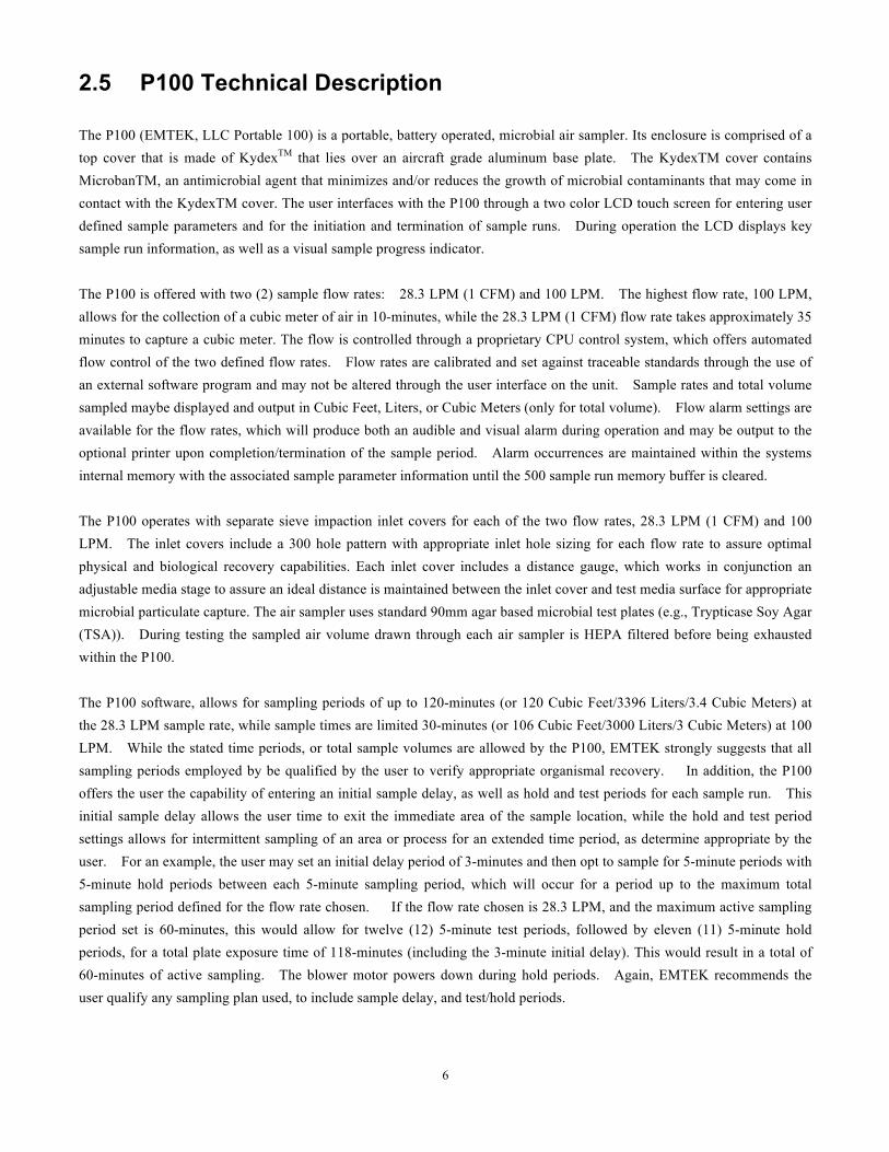
Figure 3.2.2 Optional Components
Fig. # Item Description 1 Extra Inlet Cover(s) (28.3 or 100 LPM)
2 Portable Printer Kit: Portable Printer (1), Power Adapter (1), Ethernet to RJ12 Adapter Cord (1), Label Rolls (3)
3 Horizontal Flow Inlet
4 Compressed Air/Gas Sampling Kit (100 LPM): 100 LPM Microbial HPD (6061 Aluminum), P100 Inlet Adapter, HEPA Exhaust Filters (2), Sanitary Clamp/Gasket (304SS/PTFE), ½ ID Tubing (30”)
Fig. 1-Inlet Cover (28.3 LPM Shown) Fig. 2-Portable Printer Kit
Fig. 3- Horizontal Flow Inlet Fig. 4-Compressed Air/Gas Kit
15
Section 4 Installation
English Danger Only qualified personnel should perform the tasks specified in this section.
Français
Danger Le personnel seulement qualifié devrait exécuter les tâches spécifiées dans cette section.
4.1 Wiring safety information Follow all warnings and notes when making wiring connections to the instrument (Safety information on page 8).
English DANGER Electric shock hazard. Always disconnect power to the instrument when making electrical connections.
Français DANGER Un choc électrique risque. Toujours couper l'alimentation de l'instrument lors des branchements électriques.
4.2 Electrostatic discharge (ESD) considerations
Important Note: To minimize hazards and ESD risks, maintenance procedures not requiring power to the P100 should be performed with power removed. Delicate internal electronic components can be damaged by static electricity,
resulting in degraded instrument performance or eventual failure.
Note Importante: Pour minimiser les dangers et les risques de l'EDD, les procédures d'entretien non nécessitant une alimentation à la P100 devrait être exécuté avec la puissance retirés. Interne sensible composants électroniques, peuvent être endommagés par l'électricité statique, résultant en instrument une dégradation des performances ou de l'échec éventuel.
16
The manufacturer recommends taking the following steps to prevent ESD damage to your instrument:
• Before touching any instrument electronic components (such as printed circuit cards and the components on them) discharge static electricity from the body. To discharge static electricity, touch an earth-grounded metal surface such as the chassis of an instrument, or a metal conduit or pipe. • To reduce static build-up, avoid excessive movement. Transport static-sensitive components in anti-static containers or packaging. • To discharge static electricity from the body and keep it discharged, wear a wrist strap connected by a wire to earth ground. • Handle all static-sensitive components in a static-safe area. If possible, use anti-static floor pads and work bench pads.
17
4.3 Electrical/Data Connections
English DANGER Electric shock hazard. Always disconnect power to the instrument when making electrical connections. Français DANGER Un choc électrique risque. Toujours couper l'alimentation de l'instrument lors des branchements électriques.
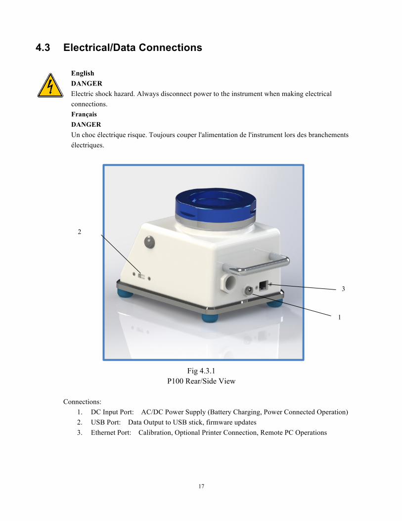
Fig 4.3.1 P100 Rear/Side View
Connections:
1. DC Input Port: AC/DC Power Supply (Battery Charging, Power Connected Operation) 2. USB Port: Data Output to USB stick, firmware updates 3. Ethernet Port: Calibration, Optional Printer Connection, Remote PC Operations
2
1
3
18
Section 5 P100 Description
5.1 P100 Front View
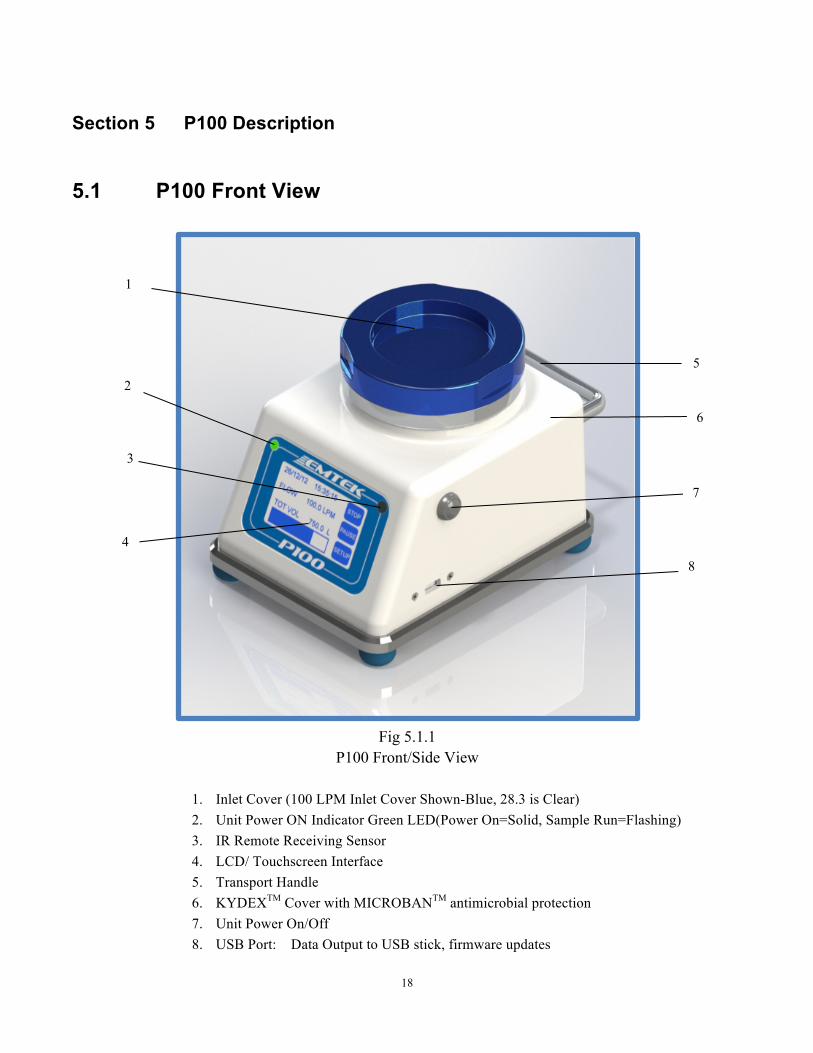
Fig 5.1.1
P100 Front/Side View
1. Inlet Cover (100 LPM Inlet Cover Shown-Blue, 28.3 is Clear) 2. Unit Power ON Indicator Green LED(Power On=Solid, Sample Run=Flashing) 3. IR Remote Receiving Sensor 4. LCD/ Touchscreen Interface 5. Transport Handle 6. KYDEXTM Cover with MICROBANTM antimicrobial protection 7. Unit Power On/Off 8. USB Port: Data Output to USB stick, firmware updates
5
2
1
3
7
4
8
6
19
5.2 P100 Rear View
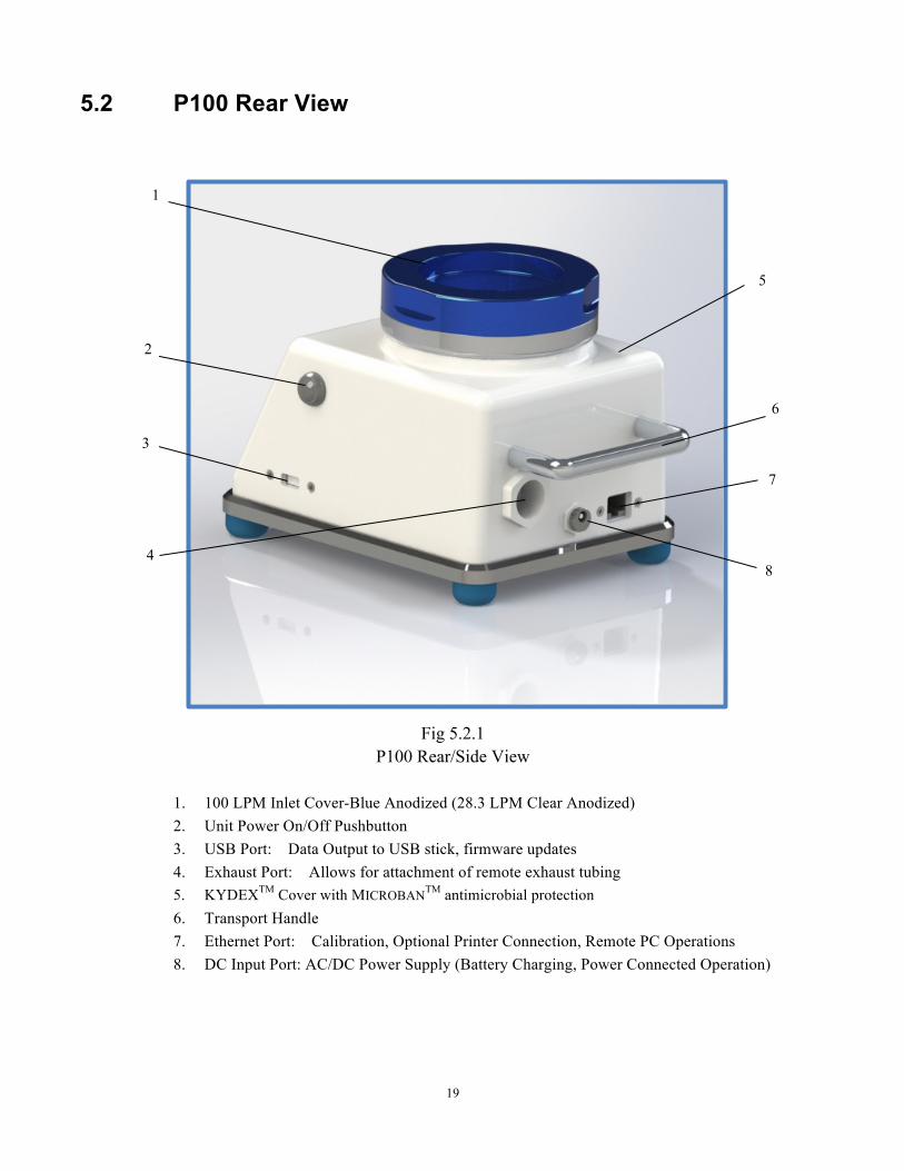
Fig 5.2.1 P100 Rear/Side View
1. 100 LPM Inlet Cover-Blue Anodized (28.3 LPM Clear Anodized) 2. Unit Power On/Off Pushbutton 3. USB Port: Data Output to USB stick, firmware updates 4. Exhaust Port: Allows for attachment of remote exhaust tubing 5. KYDEXTM Cover with MICROBANTM antimicrobial protection 6. Transport Handle 7. Ethernet Port: Calibration, Optional Printer Connection, Remote PC Operations 8. DC Input Port: AC/DC Power Supply (Battery Charging, Power Connected Operation)
8
1
5
6
4
2
7
3
20
Section 6 Quick Start Guide
If you are already familiar with the P100 Controller, follow these steps to get your controller running: 1. Turn the P100 power on using the On/Off power button on the right side of the unit. (Fig 5.1.1, #7)
NOTE: If the unit is not charged, plug the primary AC/DC power adapter cable into the power receptacle on the rear of the P100 (Fig 5.1.2, #8), and then attach to an appropriate AC power supply source that is 100-240 VAC, and 50/60 Hz.
2. Set required sample run parameters using the touch screen interface. (See Section 7.1) 3. If a label/paper output is desired, ensure that the OPTIONAL printer is attached (Fig 5.2.1, #7), turned on,
printer output is ON, and that the unit has and adequate supply of paper/labels (Section 7.8). 4. Follow the appropriate procedure to collect the required samples.

21
Section 7 Operating Instructions
7.1 Touch Screen Description & Functions
7.1.1 SETUP Screen View
General: The SETUP Screen will be shown every time the unit is powered up.
All Keys: Allow for selection and access of the specified option screen to view and/or modify those
parameters, as described in the following sections.
RUN DISP Primary display screen shown during sample runs with live data updates for the run (e.g., sample run time, volume collected, current data/time, etc.)
SET SMPL Screen used to set all sample run parameters. This includes flow rate,
volume, sample time, flow units, and volume units. PRNTR Turn printer on or off in regard to end of run printing. Set printer roll type,
paper or labels. ALARM RMT Turn IR Remote function ON/OFF. Set the IR Remote Channel for the
unit (1-5). Turn Flow Alarm ON or OFF. DLY HOLD Set sample Delay to start, and Test/Hold patterns for the sample run. SITE ID Select, Create, or Delete Site Descriptions to be assigned to each run (if
desired).
22
DATE TIME Set Date and Time Format, as well as current Date and Time. DATA Enter the number of samples to output to optional printer, or to USB drive.
Clear data runs currently stored on the unit. CAL Shows current unit Calibration Due Date. Turn Calibration Due Alarm ON
or OFF. ADMIN Add/Delete unit ADMIN account, Add/Delete unit USER Account, Set
ADMIN Options for key parameters and Functions. Adjust screen brightness/contrast, and buzzer/keypad beep/flow alarm volume.
UNIT INFO Unit Serial Number, Equipment Number, Firmware Version SAVE PRGM Save specific sampling programs, which includes: Sample Flow Rate,
selected or Set Volume, Delay/Test/Hold periods, Units for Flow and Volume
23
7.1.2 RUN DISPLAY (RUN DISP) Screen View
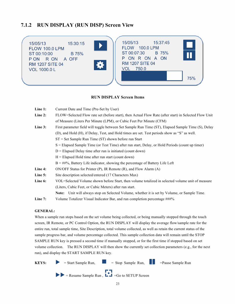
RUN DISPLAY Screen Items
Line 1: Current Date and Time (Pre-Set by User) Line 2: FLOW=Selected Flow rate set (before start), then Actual Flow Rate (after start) in Selected Flow Unit
of Measure (Liters Per Minute (LPM), or Cubic Feet Per Minute (CFM) Line 3: First parameter field will toggle between Set Sample Run Time (ST), Elapsed Sample Time (S), Delay
(D), and Hold (H), if Delay, Test, and Hold times are set. Test periods show as “S” as well. ST = Set Sample Run Time (ST) shown before run Start S = Elapsed Sample Time (or Test Time) after run start, Delay, or Hold Periods (count up timer) D = Elapsed Delay time after run is initiated (count down) H = Elapsed Hold time after run start (count down) B = ##%, Battery Life indicator, showing the percentage of Battery Life Left
Line 4: ON/OFF Status for Printer (P), IR Remote (R), and Flow Alarm (A) Line 5: Site description selected/entered (17 Characters Max) Line 6: VOL=Selected Volume shown before Start, then volume totalized in selected volume unit of measure
(Liters, Cubic Feet, or Cubic Meters) after run start. Note: Unit will always stop on Selected Volume, whether it is set by Volume, or Sample Time. Line 7: Volume Totalizer Visual Indicator Bar, and run completion percentage ###% GENERAL: When a sample run stops based on the set volume being collected, or being manually stopped through the touch screen, IR Remote, or PC Control Option, the RUN DISPLAY will display the average flow/sample rate for the entire run, total sample time, Site Description, total volume collected, as well as retain the current status of the sample progress bar, and volume percentage collected. This sample collection data will remain until the STOP SAMPLE RUN key is pressed a second time if manually stopped, or for the first time if stopped based on set volume collection. The RUN DISPLAY will then show the currently set collection parameters (e.g., for the next run), and display the START SAMPLE RUN key.
KEYS: u = Start Sample Run, n = Stop Sample Run, =Pause Sample Run
uu = Resume Sample Run , =Go to SETUP Screen
24
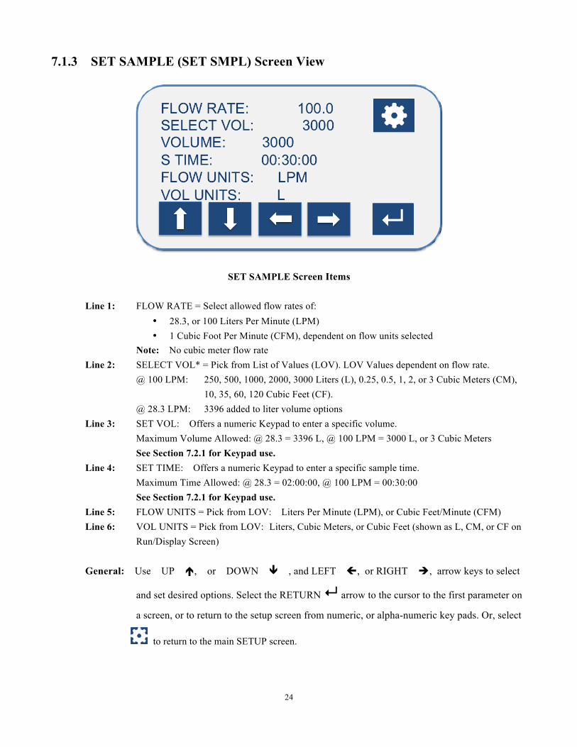
7.1.3 SET SAMPLE (SET SMPL) Screen View
SET SAMPLE Screen Items
Line 1: FLOW RATE = Select allowed flow rates of: • 28.3, or 100 Liters Per Minute (LPM) • 1 Cubic Foot Per Minute (CFM), dependent on flow units selected
Note: No cubic meter flow rate Line 2: SELECT VOL* = Pick from List of Values (LOV). LOV Values dependent on flow rate.
@ 100 LPM: 250, 500, 1000, 2000, 3000 Liters (L), 0.25, 0.5, 1, 2, or 3 Cubic Meters (CM), 10, 35, 60, 120 Cubic Feet (CF).
@ 28.3 LPM: 3396 added to liter volume options Line 3: SET VOL: Offers a numeric Keypad to enter a specific volume.
Maximum Volume Allowed: @ 28.3 = 3396 L, @ 100 LPM = 3000 L, or 3 Cubic Meters See Section 7.2.1 for Keypad use.
Line 4: SET TIME: Offers a numeric Keypad to enter a specific sample time. Maximum Time Allowed: @ 28.3 = 02:00:00, @ 100 LPM = 00:30:00 See Section 7.2.1 for Keypad use.
Line 5: FLOW UNITS = Pick from LOV: Liters Per Minute (LPM), or Cubic Feet/Minute (CFM) Line 6: VOL UNITS = Pick from LOV: Liters, Cubic Meters, or Cubic Feet (shown as L, CM, or CF on
Run/Display Screen) General: Use UP é, or DOWN ê , and LEFT ç, or RIGHT è, arrow keys to select
and set desired options. Select the RETURN ↵ arrow to the cursor to the first parameter on
a screen, or to return to the setup screen from numeric, or alpha-numeric key pads. Or, select
to return to the main SETUP screen.
25
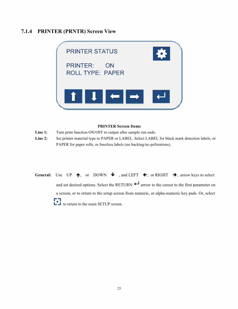
7.1.4 PRINTER (PRNTR) Screen View
PRINTER Screen Items Line 1: Turn print function ON/OFF to output after sample run ends. Line 2: Set printer material type to PAPER or LABEL. Select LABEL for black mark detection labels, or
PAPER for paper rolls, or linerless labels (no backing/no peforations). General: Use UP é, or DOWN ê , and LEFT ç, or RIGHT è, arrow keys to select
and set desired options. Select the RETURN ↵ arrow to the cursor to the first parameter on
a screen, or to return to the setup screen from numeric, or alpha-numeric key pads. Or, select
to return to the main SETUP screen.
26
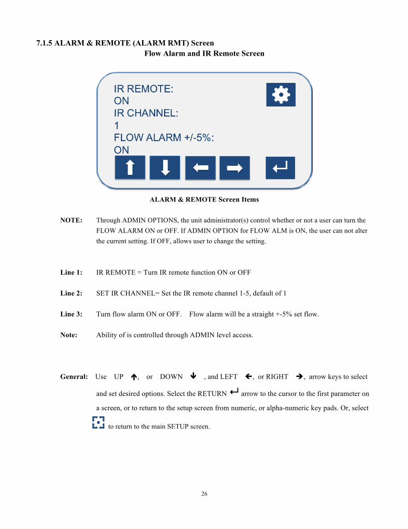
7.1.5 ALARM & REMOTE (ALARM RMT) Screen
Flow Alarm and IR Remote Screen
ALARM & REMOTE Screen Items
NOTE: Through ADMIN OPTIONS, the unit administrator(s) control whether or not a user can turn the
FLOW ALARM ON or OFF. If ADMIN OPTION for FLOW ALM is ON, the user can not alter the current setting. If OFF, allows user to change the setting.
Line 1: IR REMOTE = Turn IR remote function ON or OFF Line 2: SET IR CHANNEL= Set the IR remote channel 1-5, default of 1 Line 3: Turn flow alarm ON or OFF. Flow alarm will be a straight +-5% set flow. Note: Ability of is controlled through ADMIN level access. General: Use UP é, or DOWN ê , and LEFT ç, or RIGHT è, arrow keys to select
and set desired options. Select the RETURN ↵ arrow to the cursor to the first parameter on
a screen, or to return to the setup screen from numeric, or alpha-numeric key pads. Or, select
to return to the main SETUP screen.
27
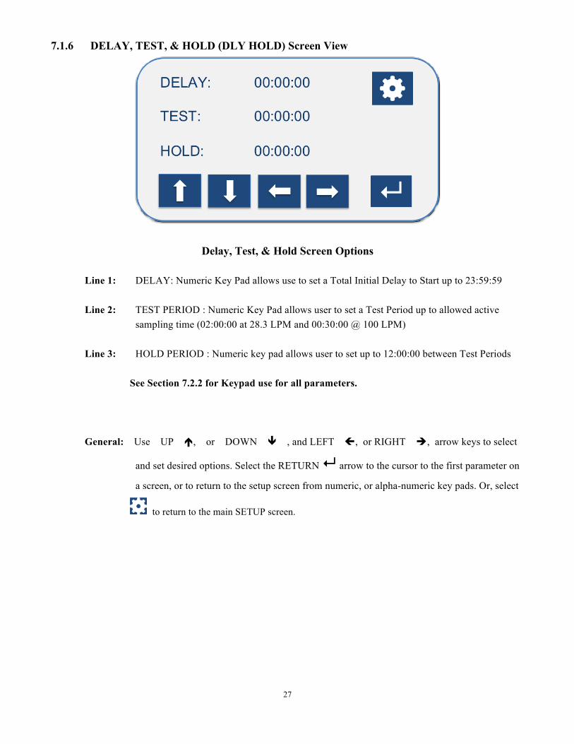
7.1.6 DELAY, TEST, & HOLD (DLY HOLD) Screen View
Delay, Test, & Hold Screen Options
Line 1: DELAY: Numeric Key Pad allows use to set a Total Initial Delay to Start up to 23:59:59 Line 2: TEST PERIOD : Numeric Key Pad allows user to set a Test Period up to allowed active
sampling time (02:00:00 at 28.3 LPM and 00:30:00 @ 100 LPM) Line 3: HOLD PERIOD : Numeric key pad allows user to set up to 12:00:00 between Test Periods
See Section 7.2.2 for Keypad use for all parameters. General: Use UP é, or DOWN ê , and LEFT ç, or RIGHT è, arrow keys to select
and set desired options. Select the RETURN ↵ arrow to the cursor to the first parameter on
a screen, or to return to the setup screen from numeric, or alpha-numeric key pads. Or, select
to return to the main SETUP screen.

28
7.1.7 SITE DESCRIPTION (SITE DESC) Screen View
Site Description Screen Options
NOTE: Through ADMIN OPTIONS, the unit administrator(s) control whether or not a user can add or
delete a Site Description. If ADMIN OPTION for SITE DESC is ON, the user can not alter the current setting. If OFF, allows user to change the setting.
Line 1: SELECT SITE DESC = Scroll through entered list of sites entered with left and right arrow keys. Line 2: Delete Desc = DELETE Site Descriptions. If a site description is shown in the SELECT SITE
DESC: field, selecting “Delete Desc” will allow you to delete the selected site description. A secondary window will pop up to prompt YES/NO for the deletion.
Line 3: Enter New Desc =ENTER Site Descriptions. Alpha/Numeric Keypad pops up to enter site
descriptions. Maximum site descriptions based on screen size, which is 17 Characters to fit screen views. See section 7.2.3 for Keypad use.
General: Use UP é, or DOWN ê , and LEFT ç, or RIGHT è, arrow keys to select
and set desired options. Select the RETURN ↵ arrow to the cursor to the first parameter on
a screen, or to return to the setup screen from numeric, or alpha-numeric key pads. Or, select
to return to the main SETUP screen.
29
7.1.8 DATE TIME Screen View
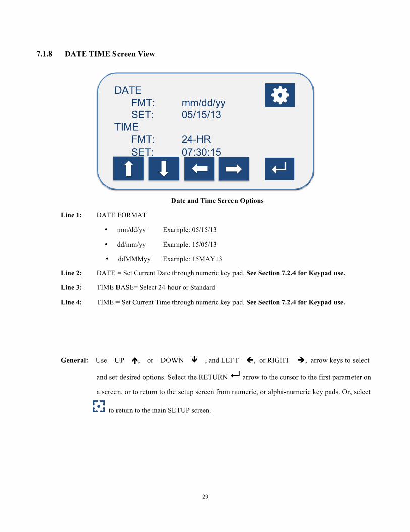
Date and Time Screen Options
Line 1: DATE FORMAT
• mm/dd/yy Example: 05/15/13
• dd/mm/yy Example: 15/05/13
• ddMMMyy Example: 15MAY13
Line 2: DATE = Set Current Date through numeric key pad. See Section 7.2.4 for Keypad use.
Line 3: TIME BASE= Select 24-hour or Standard
Line 4: TIME = Set Current Time through numeric key pad. See Section 7.2.4 for Keypad use.
General: Use UP é, or DOWN ê , and LEFT ç, or RIGHT è, arrow keys to select
and set desired options. Select the RETURN ↵ arrow to the cursor to the first parameter on
a screen, or to return to the setup screen from numeric, or alpha-numeric key pads. Or, select
to return to the main SETUP screen.
30
7.1.9 DATA Screen View
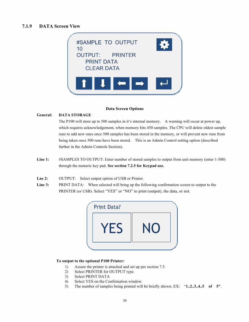
Data Screen Options
General: DATA STORAGE The P100 will store up to 500 samples in it’s internal memory. A warning will occur at power up,
which requires acknowledgement, when memory hits 450 samples. The CPU will delete oldest sample runs to add new ones once 500 samples has been stored in the memory, or will prevent new runs from being taken once 500 runs have been stored. This is an Admin Control setting option (described further in the Admin Controls Section).
Line 1: #SAMPLES TO OUTPUT: Enter number of stored samples to output from unit memory (enter 1-500)
through the numeric key pad. See section 7.2.5 for Keypad use.
Lne 2: OUTPUT: Select output option of USB or Printer. Line 3: PRINT DATA: When selected will bring up the following confirmation screen to output to the
PRINTER (or USB). Select “YES” or “NO” to print (output), the data, or not.
To output to the optional P100 Printer:
1) Assure the printer is attached and set up per section 7.5. 2) Select PRINTER for OUTPUT type. 3) Select PRINT DATA 4) Select YES on the Confirmation window. 5) The number of samples being printed will be briefly shown. EX: “1..2..3..4..5 of 5”.

31
To output to a USB stick: 1) Insert a USB stick in the USB port on the side of the unit. 2) Select USB for OUTPUT type. 3) Select PRINT DATA 4) Select YES on the Confirmation window. 5) The number of samples being output will be briefly shown. EX: “1..2..3..4..5 of 5”. 6) Remove USB stick and transfer data to a PC. Data output is CSV format. The data will open
in common spreadsheets, such as Microsoft Excel.
IMPORTANT NOTE: The data cannot be modified and then saved on the P100 unit. Once the data is saved outside of the P100 system, the data integrity is not guaranteed by EMTEK. EMTEK. LLC does not provide external software that is 21 CFR Part 11 compliant. Downloaded sample parameter data must be handled by the user in a compliant manner.
NOTE IMPORTANTE: Les données ne peuvent pas être modifiés et sauvegardés sur l'unité P100. Une fois que les
données sont sauvegardées en dehors du système P100, l'intégrité des données n'est pas garantie par EMTEK. EMTEK. LLC ne fournit pas de logiciel externe qui est la norme 21 CFR Part 11. Données de paramétrage de l'échantillon téléchargés doivent être manipulés par l'utilisateur d'une manière conforme.
Line 4: CLEAR DATA: If ON in ADMIN OPTIONS, data cannot be cleared from the unit. If OFF in
ADMIN OPTIONS the following confirmation screen will appear when you select CLEAR DATA. Select “YES” or “NO” to delete, or retain the data. Selecting “YES” will clear all data currently on the
unit.
General: Use UP é, or DOWN ê , and LEFT ç, or RIGHT è, arrow keys to select
and set desired options. Select the RETURN ↵ arrow to the cursor to the first parameter on
a screen, or to return to the setup screen from numeric, or alpha-numeric key pads. Or, select
to return to the main SETUP screen.
32
7.1.10 CALIBRATION (CALIB) Screen View
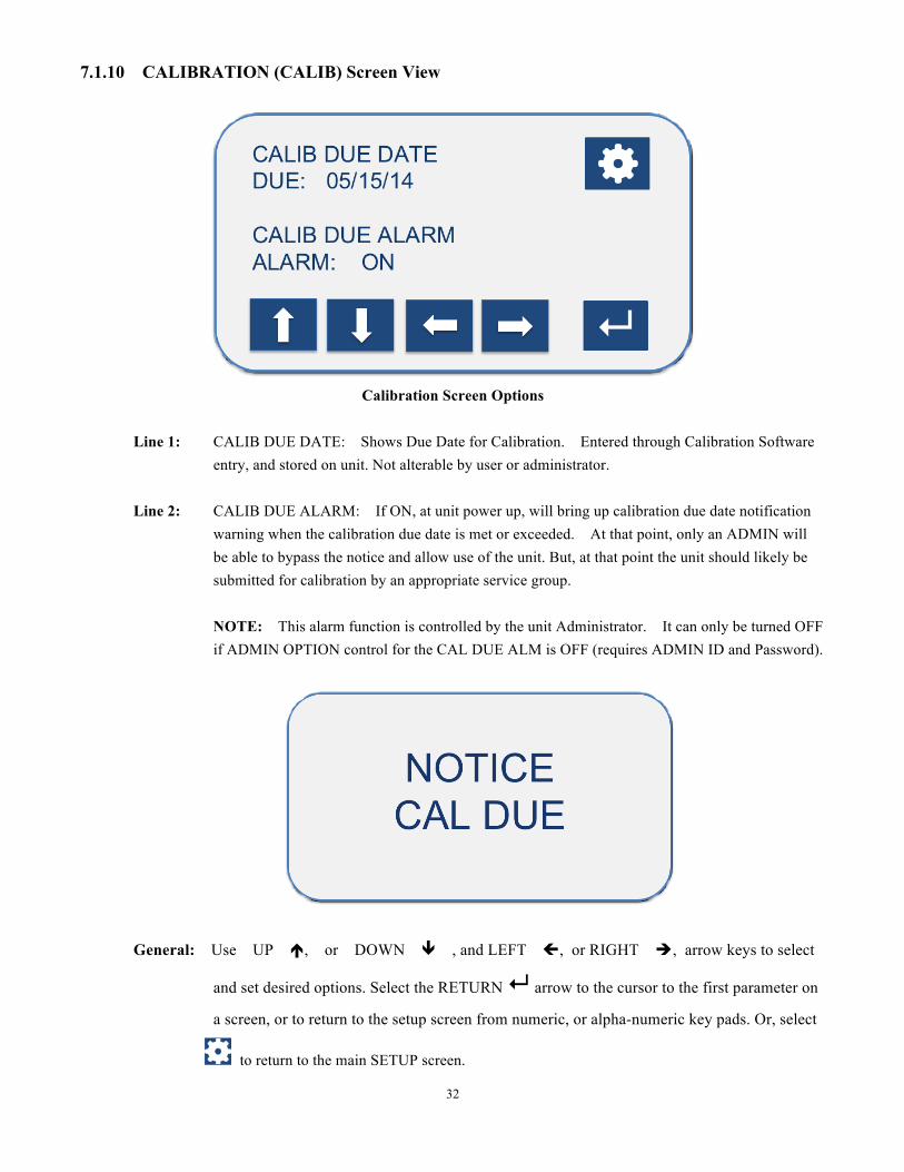
Calibration Screen Options
Line 1: CALIB DUE DATE: Shows Due Date for Calibration. Entered through Calibration Software
entry, and stored on unit. Not alterable by user or administrator. Line 2: CALIB DUE ALARM: If ON, at unit power up, will bring up calibration due date notification
warning when the calibration due date is met or exceeded. At that point, only an ADMIN will be able to bypass the notice and allow use of the unit. But, at that point the unit should likely be submitted for calibration by an appropriate service group.
NOTE: This alarm function is controlled by the unit Administrator. It can only be turned OFF if ADMIN OPTION control for the CAL DUE ALM is OFF (requires ADMIN ID and Password).
General: Use UP é, or DOWN ê , and LEFT ç, or RIGHT è, arrow keys to select
and set desired options. Select the RETURN ↵ arrow to the cursor to the first parameter on
a screen, or to return to the setup screen from numeric, or alpha-numeric key pads. Or, select
to return to the main SETUP screen.
33
7.1.11 ADMINISTRATIVE (ADMIN) Screen View
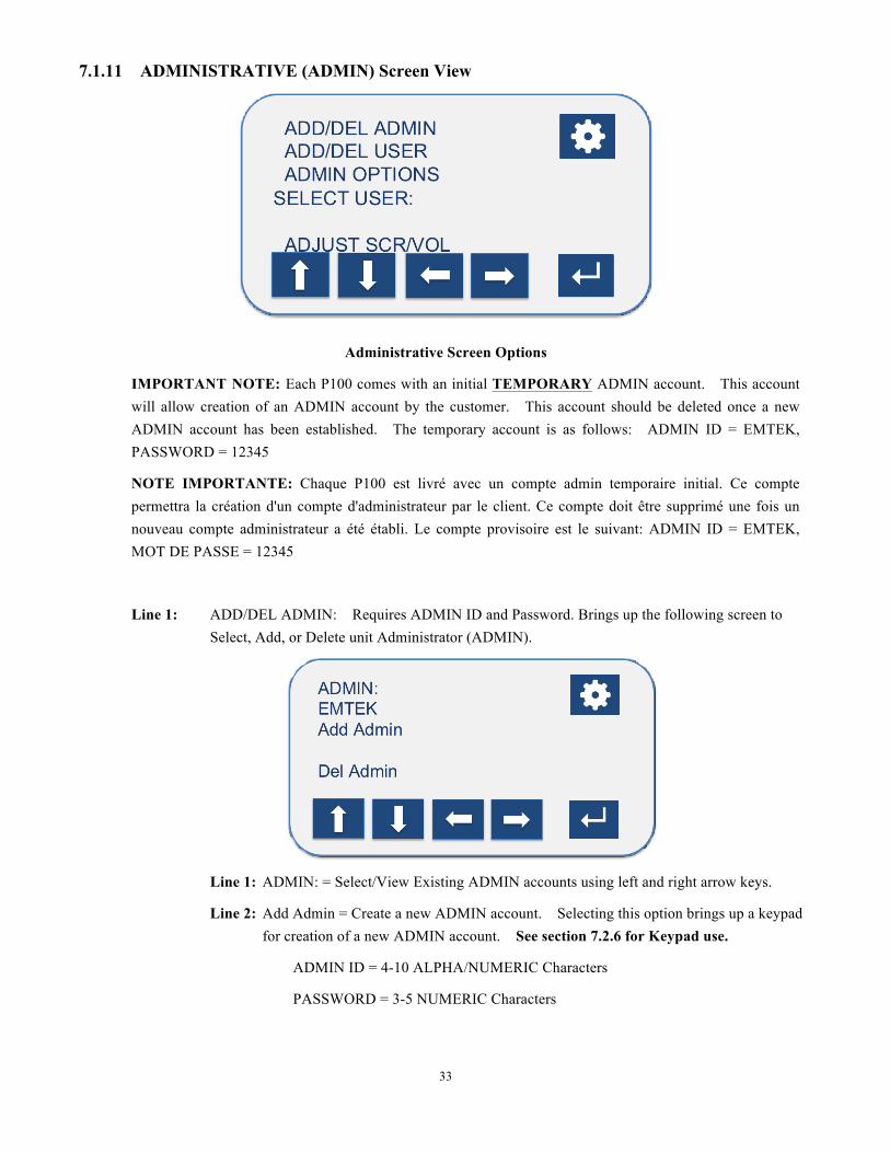
Administrative Screen Options
IMPORTANT NOTE: Each P100 comes with an initial TEMPORARY ADMIN account. This account will allow creation of an ADMIN account by the customer. This account should be deleted once a new ADMIN account has been established. The temporary account is as follows: ADMIN ID = EMTEK, PASSWORD = 12345
NOTE IMPORTANTE: Chaque P100 est livré avec un compte admin temporaire initial. Ce compte permettra la création d'un compte d'administrateur par le client. Ce compte doit être supprimé une fois un nouveau compte administrateur a été établi. Le compte provisoire est le suivant: ADMIN ID = EMTEK, MOT DE PASSE = 12345
Line 1: ADD/DEL ADMIN: Requires ADMIN ID and Password. Brings up the following screen to Select, Add, or Delete unit Administrator (ADMIN).
Line 1: ADMIN: = Select/View Existing ADMIN accounts using left and right arrow keys.
Line 2: Add Admin = Create a new ADMIN account. Selecting this option brings up a keypad for creation of a new ADMIN account. See section 7.2.6 for Keypad use.
ADMIN ID = 4-10 ALPHA/NUMERIC Characters
PASSWORD = 3-5 NUMERIC Characters
34
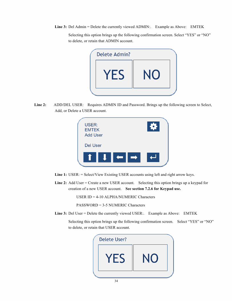
Line 3: Del Admin = Delete the currently viewed ADMIN:. Example as Above: EMTEK
Selecting this option brings up the following confirmation screen. Select “YES” or “NO” to delete, or retain that ADMIN account.
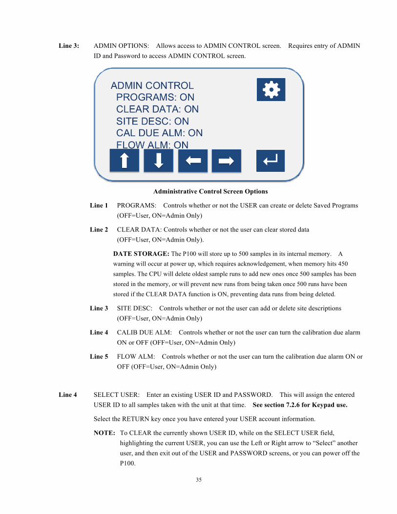
Line 2: ADD/DEL USER: Requires ADMIN ID and Password. Brings up the following screen to Select, Add, or Delete a USER account.
Line 1: USER: = Select/View Existing USER accounts using left and right arrow keys.
Line 2: Add User = Create a new USER account. Selecting this option brings up a keypad for creation of a new USER account. See section 7.2.6 for Keypad use.
USER ID = 4-10 ALPHA/NUMERIC Characters
PASSWORD = 3-5 NUMERIC Characters
Line 3: Del User = Delete the currently viewed USER:. Example as Above: EMTEK
Selecting this option brings up the following confirmation screen. Select “YES” or “NO” to delete, or retain that USER account.
35
Line 3: ADMIN OPTIONS: Allows access to ADMIN CONTROL screen. Requires entry of ADMIN ID and Password to access ADMIN CONTROL screen.
Administrative Control Screen Options
Line 1 PROGRAMS: Controls whether or not the USER can create or delete Saved Programs (OFF=User, ON=Admin Only)
Line 2 CLEAR DATA: Controls whether or not the user can clear stored data (OFF=User, ON=Admin Only).
DATE STORAGE: The P100 will store up to 500 samples in its internal memory. A warning will occur at power up, which requires acknowledgement, when memory hits 450 samples. The CPU will delete oldest sample runs to add new ones once 500 samples has been stored in the memory, or will prevent new runs from being taken once 500 runs have been stored if the CLEAR DATA function is ON, preventing data runs from being deleted.
Line 3 SITE DESC: Controls whether or not the user can add or delete site descriptions (OFF=User, ON=Admin Only)
Line 4 CALIB DUE ALM: Controls whether or not the user can turn the calibration due alarm ON or OFF (OFF=User, ON=Admin Only)
Line 5 FLOW ALM: Controls whether or not the user can turn the calibration due alarm ON or OFF (OFF=User, ON=Admin Only)
Line 4 SELECT USER: Enter an existing USER ID and PASSWORD. This will assign the entered USER ID to all samples taken with the unit at that time. See section 7.2.6 for Keypad use.
Select the RETURN key once you have entered your USER account information.
NOTE: To CLEAR the currently shown USER ID, while on the SELECT USER field, highlighting the current USER, you can use the Left or Right arrow to “Select” another user, and then exit out of the USER and PASSWORD screens, or you can power off the P100.

36
Line 5 ADJUST SCR/VOL: Brings up the following screen, which allows adjustment BACKLIGHT intensity and CONTRAST (Common Values Shown), as well as unit BUZZER/ALARM.
Line 1: BACKLIGHT: Adjust brightness of screen up or down.
Line 2: CONTRAST: Adjust character contrast to general screen brightness.
Line 3: BUZZER: ON/OFF selection for Keypad “Beeps”, Flow Alarm, End of Run Alarm
Line 4: VOLUME: Adjust volume of Alarm, Buzzer, Beeps (scaled 1-20).
General: Use UP é, or DOWN ê , and LEFT ç, or RIGHT è, arrow keys to select
and set desired options. Select the RETURN ↵ arrow to the cursor to the first parameter on
a screen, or to return to the setup screen from numeric, or alpha-numeric key pads. Or, select
to return to the main SETUP screen.
37
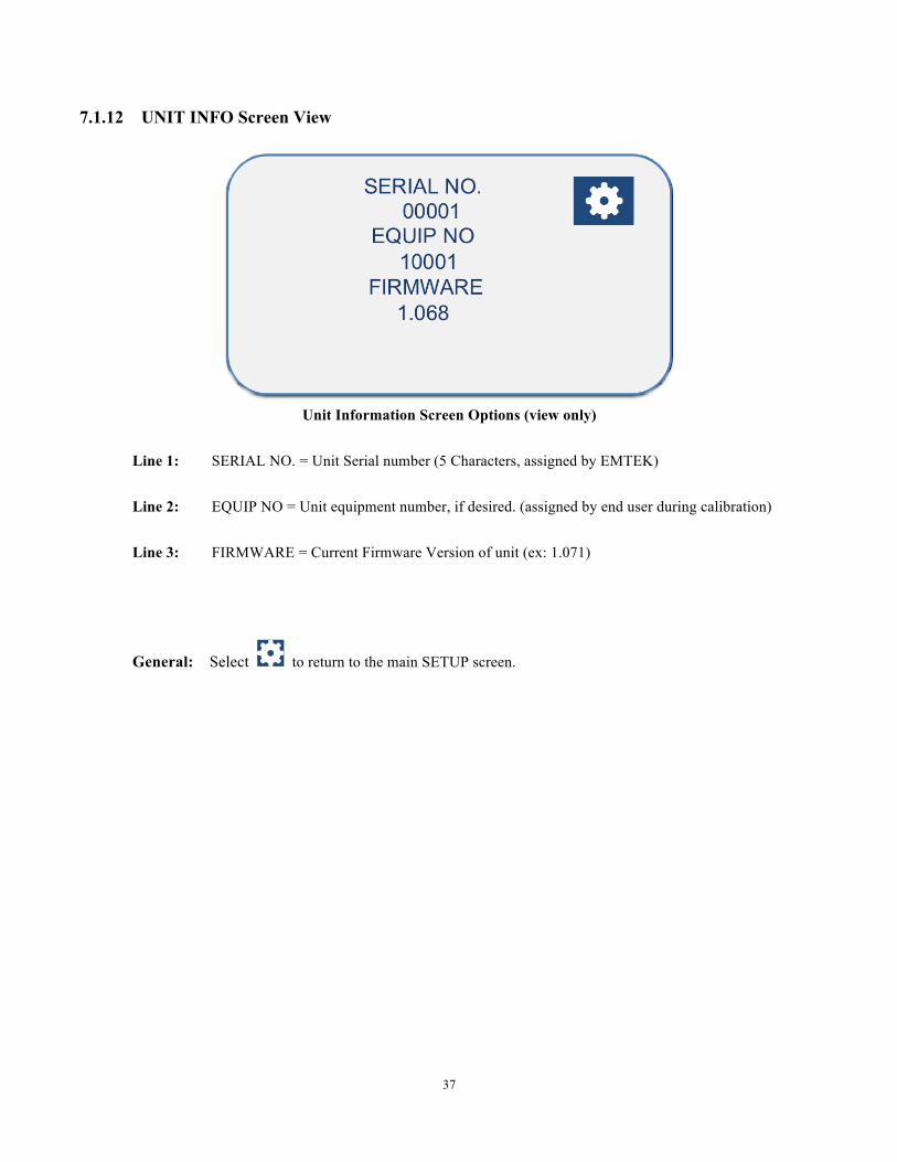
7.1.12 UNIT INFO Screen View
Unit Information Screen Options (view only)
Line 1: SERIAL NO. = Unit Serial number (5 Characters, assigned by EMTEK) Line 2: EQUIP NO = Unit equipment number, if desired. (assigned by end user during calibration) Line 3: FIRMWARE = Current Firmware Version of unit (ex: 1.071)
General: Select to return to the main SETUP screen.

38
7.1.13 SAVE PROGRAM Screen View
Save Program Screen Options
NOTE: Through ADMIN OPTIONS, the unit administrator(s) control whether or not a user can add or
delete a program.
Line 1 SAVED PROGRAMS: User can select a previously added program to use from the list of values.
Line 2 ADD PROGRAM: Capture the current settings (described below) on the unit, under the entered
program name. The program name can be no longer than 17 characters in length. See section 7.2.3 for keypad use.
ADD PROGRAM will capture the following parameters currently set on the unit, under the entered Program Name:
• Flow Rate (ex: 100.0) • Selected or Set Volume (whether entered by vol or time) (ex: 1000) • Delay, Test, and Hold periods (ex: D 00:00:15, T 00:01:00, H 00:01:00) • Units for Flow and Volume (ex: LPM and L)
Line 3 DELETE PROGRAM: Delete the currently shown program under SAVED PROGRAMS. The
following confirmation window will appear. Select “YES” or “NO” to delete or retain the program.

39
General: Use UP é, or DOWN ê , and LEFT ç, or RIGHT è, arrow keys to select
and set desired options. Select the RETURN ↵ arrow to the cursor to the first parameter on
a screen, or to return to the setup screen from numeric, or alpha-numeric key pads. Or, select
to return to the main SETUP screen.
40
7.2 Using the Keypad Function for Entering Site/Sample
Descriptions
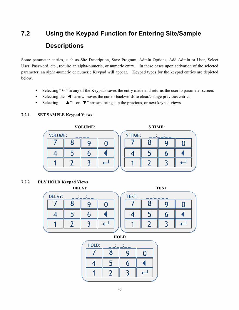
Some parameter entries, such as Site Description, Save Program, Admin Options, Add Admin or User, Select User, Password, etc., require an alpha-numeric, or numeric entry. In these cases upon activation of the selected parameter, an alpha-numeric or numeric Keypad will appear. Keypad types for the keypad entries are depicted below.
• Selecting “↵” in any of the Keypads saves the entry made and returns the user to parameter screen. • Selecting the “t” arrow moves the cursor backwords to clear/change previous entries • Selecting “p” or “q” arrows, brings up the previous, or next keypad views.
7.2.1 SET SAMPLE Keypad Views
VOLUME: S TIME:
7.2.2 DLY HOLD Keypad Views
DELAY TEST
HOLD
41
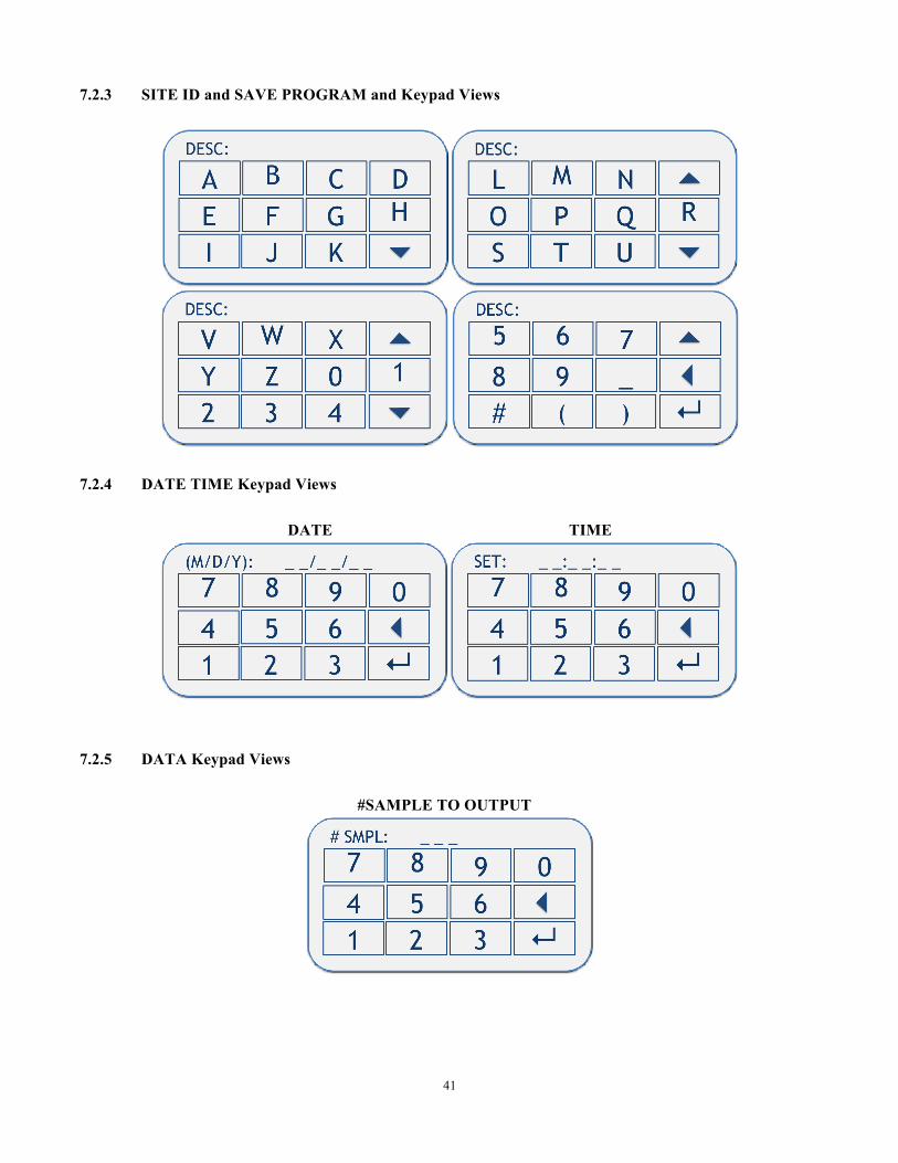
7.2.3 SITE ID and SAVE PROGRAM and Keypad Views
7.2.4 DATE TIME Keypad Views
DATE TIME
7.2.5 DATA Keypad Views #SAMPLE TO OUTPUT
42
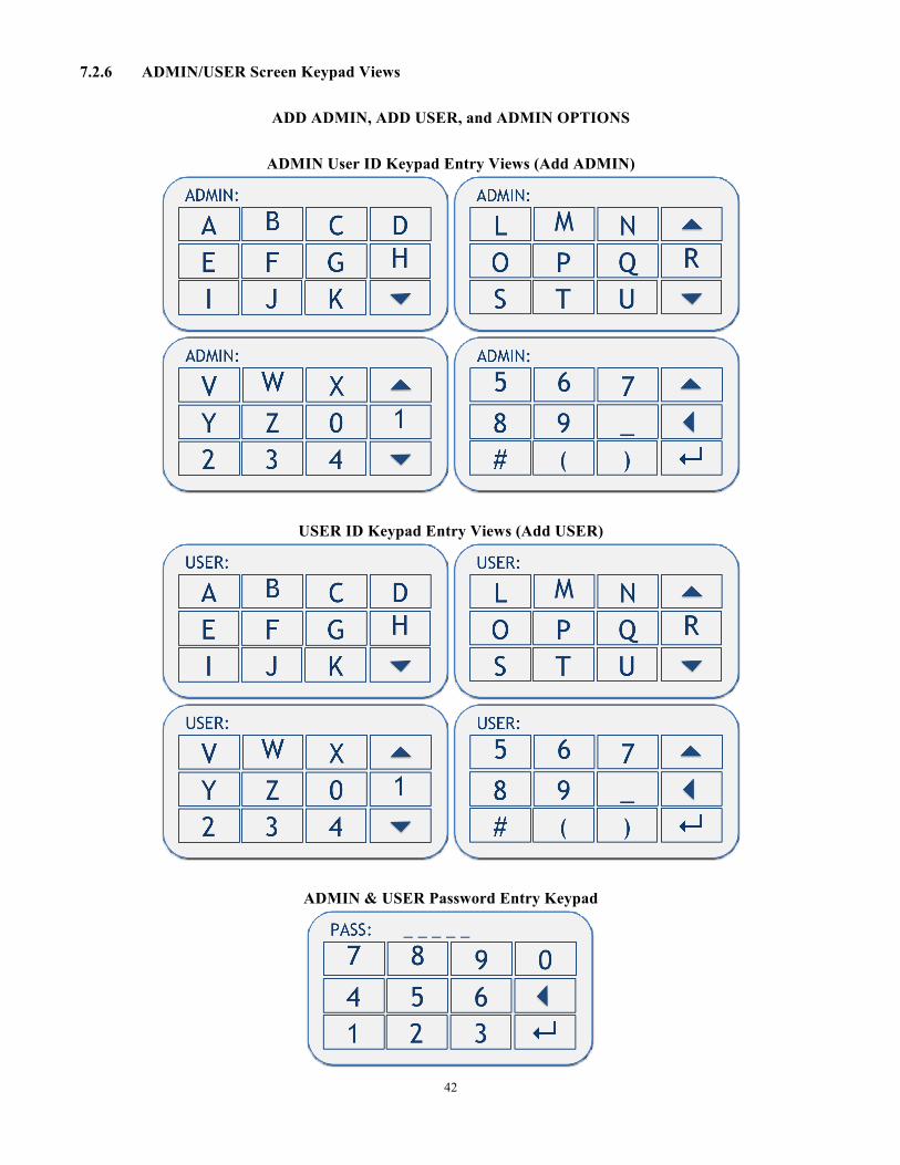
7.2.6 ADMIN/USER Screen Keypad Views
ADD ADMIN, ADD USER, and ADMIN OPTIONS
ADMIN User ID Keypad Entry Views (Add ADMIN)
USER ID Keypad Entry Views (Add USER)
ADMIN & USER Password Entry Keypad
43
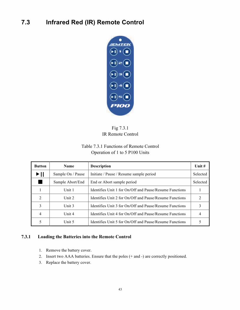
7.3 Infrared Red (IR) Remote Control
Fig 7.3.1
IR Remote Control
Table 7.3.1 Functions of Remote Control Operation of 1 to 5 P100 Units
Button Name Description Unit #
u ⎢⎢ Sample On / Pause Initiate / Pause / Resume sample period Selected
Sample Abort/End End or Abort sample period Selected
1 Unit 1 Identifies Unit 1 for On/Off and Pause/Resume Functions 1
2 Unit 2 Identifies Unit 2 for On/Off and Pause/Resume Functions 2
3 Unit 3 Identifies Unit 3 for On/Off and Pause/Resume Functions 3
4 Unit 4 Identifies Unit 4 for On/Off and Pause/Resume Functions 4
5 Unit 5 Identifies Unit 5 for On/Off and Pause/Resume Functions 5
7.3.1 Loading the Batteries into the Remote Control
1. Remove the battery cover. 2. Insert two AAA batteries. Ensure that the poles (+ and -) are correctly positioned. 3. Replace the battery cover.
44
7.3.2 Operating the P100 with the Remote Control
1. To start the sampling period, press the Start key of the unit to be operated (1-5).
2. To pause the sampling period, press the key while the unit is sampling.
4. To resume the sampling period, press the key and the sample period resumes.
5. To stop the sampling period, press the key.
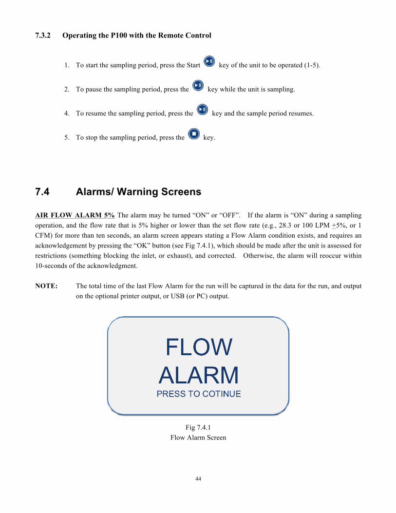
7.4 Alarms/ Warning Screens
AIR FLOW ALARM 5% The alarm may be turned “ON” or “OFF”. If the alarm is “ON” during a sampling operation, and the flow rate that is 5% higher or lower than the set flow rate (e.g., 28.3 or 100 LPM +5%, or 1 CFM) for more than ten seconds, an alarm screen appears stating a Flow Alarm condition exists, and requires an acknowledgement by pressing the “OK” button (see Fig 7.4.1), which should be made after the unit is assessed for restrictions (something blocking the inlet, or exhaust), and corrected. Otherwise, the alarm will reoccur within 10-seconds of the acknowledgment. NOTE: The total time of the last Flow Alarm for the run will be captured in the data for the run, and output
on the optional printer output, or USB (or PC) output.
Fig 7.4.1 Flow Alarm Screen
45
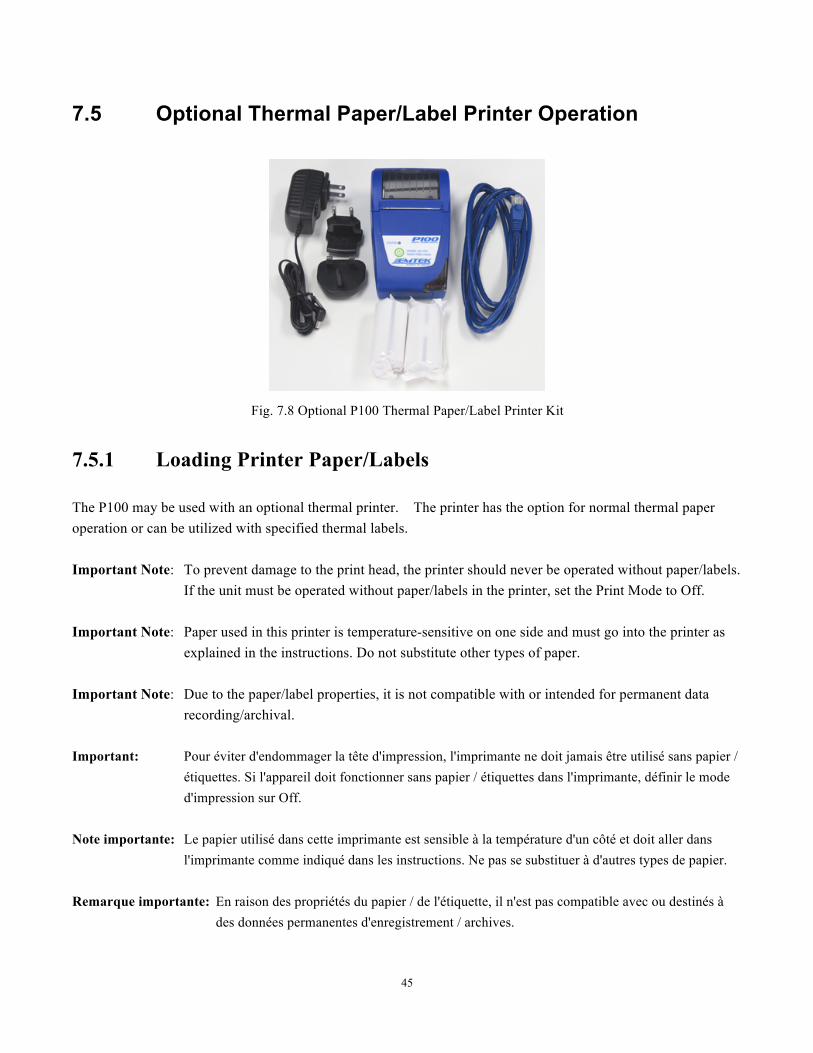
7.5 Optional Thermal Paper/Label Printer Operation
Fig. 7.8 Optional P100 Thermal Paper/Label Printer Kit
7.5.1 Loading Printer Paper/Labels
The P100 may be used with an optional thermal printer. The printer has the option for normal thermal paper operation or can be utilized with specified thermal labels.
Important Note: To prevent damage to the print head, the printer should never be operated without paper/labels.
If the unit must be operated without paper/labels in the printer, set the Print Mode to Off.
Important Note: Paper used in this printer is temperature-sensitive on one side and must go into the printer as explained in the instructions. Do not substitute other types of paper.
Important Note: Due to the paper/label properties, it is not compatible with or intended for permanent data
recording/archival. Important: Pour éviter d'endommager la tête d'impression, l'imprimante ne doit jamais être utilisé sans papier /
étiquettes. Si l'appareil doit fonctionner sans papier / étiquettes dans l'imprimante, définir le mode d'impression sur Off.
Note importante: Le papier utilisé dans cette imprimante est sensible à la température d'un côté et doit aller dans l'imprimante comme indiqué dans les instructions. Ne pas se substituer à d'autres types de papier.
Remarque importante: En raison des propriétés du papier / de l'étiquette, il n'est pas compatible avec ou destinés à des données permanentes d'enregistrement / archives.

46
To install a roll of printer paper/labels ( see Fig 7.5.1): 1. View the printer from the front with printer labeling oriented normally for reading. 2. Pull up the handle in the top center of the “clear” paper cover until a click is heard, which releases the door
mechanism. 3. Lift the door up and back (remove the core from the previous roll if applicable). 4. Install the new paper, or label roll so the paper feeds from the bottom of the roll. 5. Hold the end of the label or paper roll forward while closing the printer door, until it clicks into place, locking
it shut. 6. Alignment for Paper or Label:
6a. If using black mark detection labels, position the middle of the black mark near the printers serrated cutting edges on the printers door and case. You can manually pull the paper forward, or with the printer turned on, hold down the power button to advance or feed the labels. NOTE: Select and use the “LABEL” setting for “ROLL TYPE” in the P100 Printer Settings.
6b. If paper, or label stock without backing is used, no specific label alignment is required. NOTE: Select and use the “PAPER” for “ROLL TYPE” in the P100 Printer Settings.
7. Tear the excess paper, or label stock off the printer by pulling it forward against the printers serrated edge. 8. The paper or label stock is loaded and the printer is ready for use.
Note: If the paper does not feed out or no image appears on the paper after a print command has been sent, perform the
described steps, but check the orientation of the paper roll in the printer assembly. If the battery power is low, the print output will be become very faint. Plug the printer into its power supply/charger if this occurs.
Fig 7.5.1 Loading Paper, or Label Roll in Thermal Printer
Step 1 Step 2 Step 3 Step 4
Step 5 Step 6 Step 7 Step 8

47
Attaching the Ethernet-to-RJ12 Communication Cable Between P100 & Printer
Attach Ethernet Plug End to P100 Ethernet Port
Attach RJ12 Connector End to P100 Printer Port & Pull Cable into Cable Pass Through Slot
To Turn on the Printer: Press (DO NOT HOLD) the green power button. A green LED will turn on. It should be a solid green light. If it is flashing, or does not come on, the battery is low. Plug it into its power supply and charge for 2-3 hours before use. NOTE: The printer batteries have to be partially charged to be able to run the unit while charging, if
desired. To Feed the Label, or Paper Stock: With the printer power on, hold down the power button until the label/paper stock feed as far as desired.
48
7.6 Replacing the HEPA Filter and/or Battery Pack
The P100 is equipped with a HEPA filter exhaust. It is recommended to replace the HEPA filter every 12 months as part of periodic maintenance. The battery pack may need replacement within 3-5 years. To replace the HEPA filter, or battery pack, contact EMTEK, or your local area service representative. Only certified service technicians should perform a filter, or battery change
7.7 Touch Screen Sensor Calibration
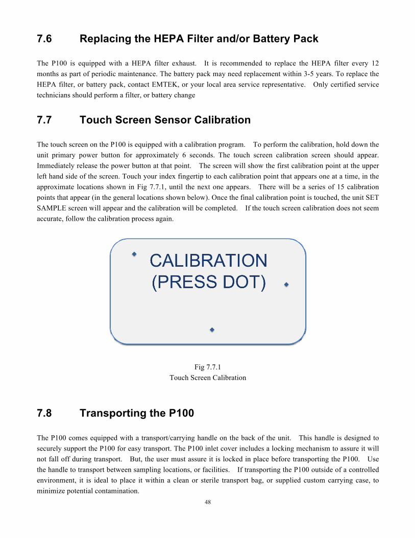
The touch screen on the P100 is equipped with a calibration program. To perform the calibration, hold down the unit primary power button for approximately 6 seconds. The touch screen calibration screen should appear. Immediately release the power button at that point. The screen will show the first calibration point at the upper left hand side of the screen. Touch your index fingertip to each calibration point that appears one at a time, in the approximate locations shown in Fig 7.7.1, until the next one appears. There will be a series of 15 calibration points that appear (in the general locations shown below). Once the final calibration point is touched, the unit SET SAMPLE screen will appear and the calibration will be completed. If the touch screen calibration does not seem accurate, follow the calibration process again.
Fig 7.7.1 Touch Screen Calibration
7.8 Transporting the P100
The P100 comes equipped with a transport/carrying handle on the back of the unit. This handle is designed to securely support the P100 for easy transport. The P100 inlet cover includes a locking mechanism to assure it will not fall off during transport. But, the user must assure it is locked in place before transporting the P100. Use the handle to transport between sampling locations, or facilities. If transporting the P100 outside of a controlled environment, it is ideal to place it within a clean or sterile transport bag, or supplied custom carrying case, to minimize potential contamination.
49
Section 8 Network Operation of the P100
The Ethernet port is provided to allow for the Calibration of the unit via an external Calibration Software Program. Contact EMTEK, LLC for more information regarding the Calibration Software Program. The P100 is equipped with an Ethernet 10Base-T/100Base-T Port that will allow for an optional PC based software program to view or extract the Sample Run Data (Run Data), and/or operate the P100 units connected to the Ethernet. The Sample Run Data can be downloaded or viewed, but cannot be modified while within the units memory. Contact EMTEK, LLC for more information regarding the PC based remote operation software program.
50
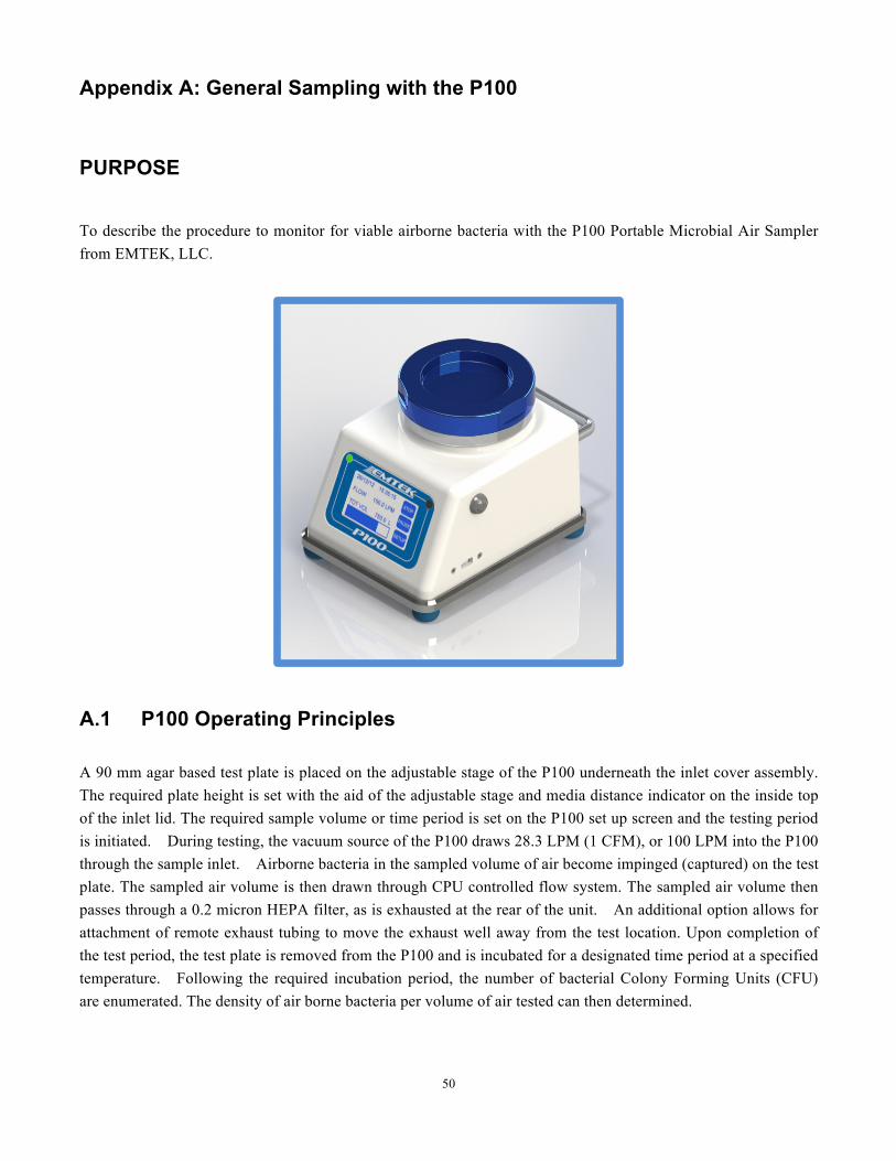
Appendix A: General Sampling with the P100
PURPOSE
To describe the procedure to monitor for viable airborne bacteria with the P100 Portable Microbial Air Sampler from EMTEK, LLC.
A.1 P100 Operating Principles
A 90 mm agar based test plate is placed on the adjustable stage of the P100 underneath the inlet cover assembly. The required plate height is set with the aid of the adjustable stage and media distance indicator on the inside top of the inlet lid. The required sample volume or time period is set on the P100 set up screen and the testing period is initiated. During testing, the vacuum source of the P100 draws 28.3 LPM (1 CFM), or 100 LPM into the P100 through the sample inlet. Airborne bacteria in the sampled volume of air become impinged (captured) on the test plate. The sampled air volume is then drawn through CPU controlled flow system. The sampled air volume then passes through a 0.2 micron HEPA filter, as is exhausted at the rear of the unit. An additional option allows for attachment of remote exhaust tubing to move the exhaust well away from the test location. Upon completion of the test period, the test plate is removed from the P100 and is incubated for a designated time period at a specified temperature. Following the required incubation period, the number of bacterial Colony Forming Units (CFU) are enumerated. The density of air borne bacteria per volume of air tested can then determined.
51
A.2 Materials
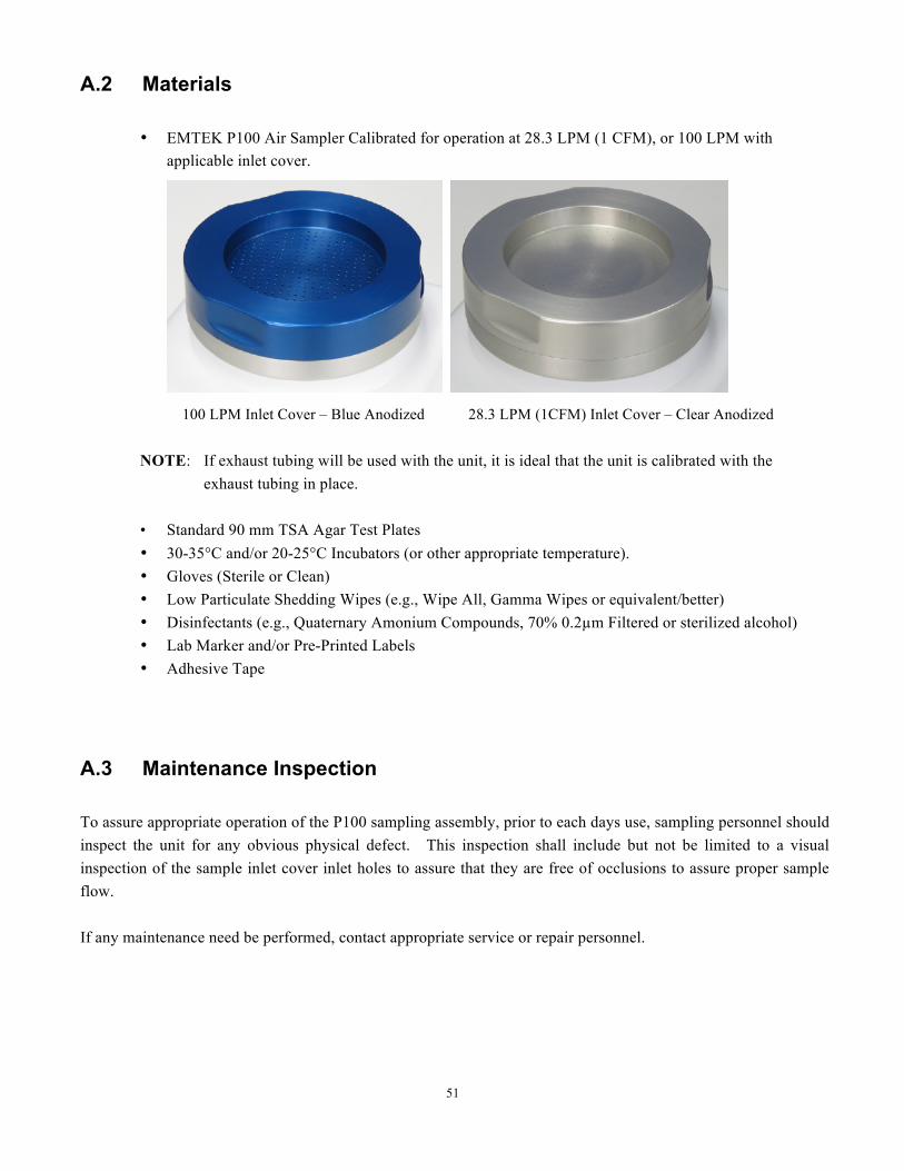
• EMTEK P100 Air Sampler Calibrated for operation at 28.3 LPM (1 CFM), or 100 LPM with applicable inlet cover.
100 LPM Inlet Cover – Blue Anodized 28.3 LPM (1CFM) Inlet Cover – Clear Anodized
NOTE: If exhaust tubing will be used with the unit, it is ideal that the unit is calibrated with the exhaust tubing in place.
• Standard 90 mm TSA Agar Test Plates • 30-35°C and/or 20-25°C Incubators (or other appropriate temperature). • Gloves (Sterile or Clean) • Low Particulate Shedding Wipes (e.g., Wipe All, Gamma Wipes or equivalent/better) • Disinfectants (e.g., Quaternary Amonium Compounds, 70% 0.2µm Filtered or sterilized alcohol) • Lab Marker and/or Pre-Printed Labels • Adhesive Tape
A.3 Maintenance Inspection
To assure appropriate operation of the P100 sampling assembly, prior to each days use, sampling personnel should inspect the unit for any obvious physical defect. This inspection shall include but not be limited to a visual inspection of the sample inlet cover inlet holes to assure that they are free of occlusions to assure proper sample flow. If any maintenance need be performed, contact appropriate service or repair personnel.
52
IMPORTANT SAFETY PRECAUTIONS!!
English TO MINIMIZE THE CHANCE OF ELECTRICAL HAZARD, assure that the AC/DC power supply cord is not plugged in during sanitization.
DO NOT REMOVE THE PANELS or COVERS of the P100 to attempt any repairs. Contact EMTEK, LLC or other qualified service personnel if the unit malfunctions. DO NOT SUBMERSE the P100 in any liquids! TAKE ALL OTHER STANDARD ELECTRICAL SAFETY PRECAUTIONS when operating the P100 Air Sampler. Français
AFIN DE RÉDUIRE LES RISQUES DE RISQUE ÉLECTRIQUE, s'assurer que le cordon d'alimentation AC / DC n'est pas branché au cours de désinfection. Ne pas retirer les panneaux ou le capot de la P100 pour tenter une réparation. Contacter EMTEK, LLC ou autres membres du personnel d'entretien qualifié en cas de dysfonctionnement de l'appareil. Ne plonger le P100 dans les liquides! Prenez tous les autres précautions de sécurité électrique standard en mode de l'échantillonneur d'air P100.
A.4 P100 Sampler Assembly Set-Up and Testing NOTES: Before sampling with the P100:
• Perform the sanitization procedure in Appendix B. • The P100 must be calibrated as a system with the desired configuration (28.3 LPM (1CFM) or 100 LPM
inlet cover). Both the 28.3 LPM and 100 LPM can be calibrated on each unit.
1. P100 Sampling Assembly Set-Up and Testing
1.1 Upon completion of sanitization per Appendix B (If applicable), place the P100 at the desired test site.
1.2 Initiate unit power as follows:
1.2.1 Turn on the unit power switch found at the bottom back corner of the P100 controller unit.
53
NOTE: The unit can run off of internal battery power, or directly from the AC/DC power adapter.
The unit must have 1% power before it will run directly from the AC/DC power source if the battery has been completely depleted.
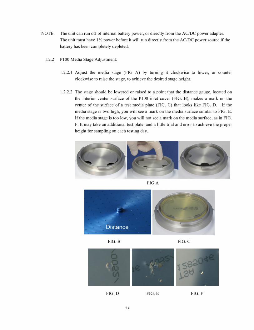
1.2.2 P100 Media Stage Adjustment:
1.2.2.1 Adjust the media stage (FIG A) by turning it clockwise to lower, or counter
clockwise to raise the stage, to achieve the desired stage height. 1.2.2.2 The stage should be lowered or raised to a point that the distance gauge, located on
the interior center surface of the P100 inlet cover (FIG. B), makes a mark on the center of the surface of a test media plate (FIG. C) that looks like FIG. D. If the media stage is two high, you will see a mark on the media surface similar to FIG. E. If the media stage is too low, you will not see a mark on the media surface, as in FIG. F. It may take an additional test plate, and a little trial and error to achieve the proper height for sampling on each testing day.
FIG A
FIG. B FIG. C
FIG. D FIG. E FIG. F
Distance
54
1.4.4 If the P100 has been chemically sanitized, ensure residual disinfectant and particulate matter
from cleaning and set up are removed from the inlet lid and sample chamber by drying with a clean or sterile wipe and purging the unit prior to initiating testing.
1.4.4.1 With the inlet lid in place and no media on the stage, start the P100 and run the P100
for 1-2 minutes (see Section 7). 1.4.4.5 Check to ensure that the P100 inlet cover is physically dry. Run the unit
additionally, as necessary, until visibly dry.
1.5 Begin testing by following the steps below:
1.5.1 Set the sample parameters on the P100 to sample for the desired flow rate and sample volume/sample time (see Section 7).
NOTE: An initial sample delay can be set to allow for clearance of the area by personnel prior to the
start of sampling. A test/hold function is also available as well as IR remote control (see Section 7).
1.5.2 Aseptically place the test plate (i.e., 90 mm TSA plate) on the media stage as follows:
NOTE: Gloved hands should be cleaned with secondary disinfectant and allowed to dry immediately
prior to performing these steps.
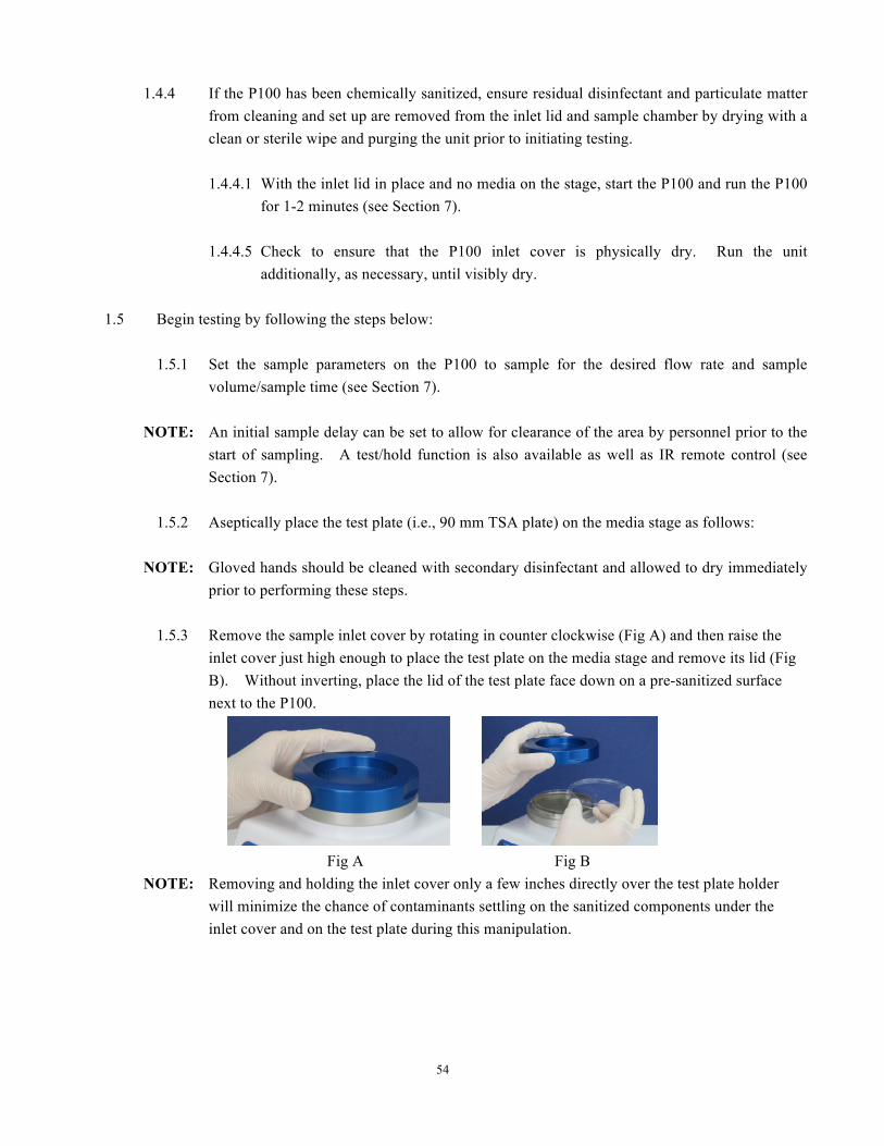
1.5.3 Remove the sample inlet cover by rotating in counter clockwise (Fig A) and then raise the inlet cover just high enough to place the test plate on the media stage and remove its lid (Fig B). Without inverting, place the lid of the test plate face down on a pre-sanitized surface next to the P100.
Fig A Fig B
NOTE: Removing and holding the inlet cover only a few inches directly over the test plate holder will minimize the chance of contaminants settling on the sanitized components under the inlet cover and on the test plate during this manipulation.
55
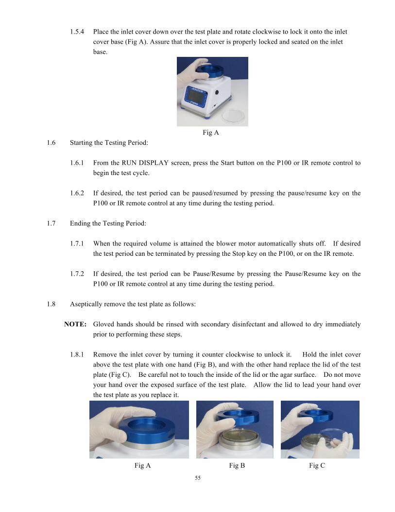
1.5.4 Place the inlet cover down over the test plate and rotate clockwise to lock it onto the inlet cover base (Fig A). Assure that the inlet cover is properly locked and seated on the inlet base.
Fig A
1.6 Starting the Testing Period:
1.6.1 From the RUN DISPLAY screen, press the Start button on the P100 or IR remote control to begin the test cycle.
1.6.2 If desired, the test period can be paused/resumed by pressing the pause/resume key on the
P100 or IR remote control at any time during the testing period.
1.7 Ending the Testing Period:
1.7.1 When the required volume is attained the blower motor automatically shuts off. If desired the test period can be terminated by pressing the Stop key on the P100, or on the IR remote.
1.7.2 If desired, the test period can be Pause/Resume by pressing the Pause/Resume key on the
P100 or IR remote control at any time during the testing period.
1.8 Aseptically remove the test plate as follows:
NOTE: Gloved hands should be rinsed with secondary disinfectant and allowed to dry immediately prior to performing these steps.
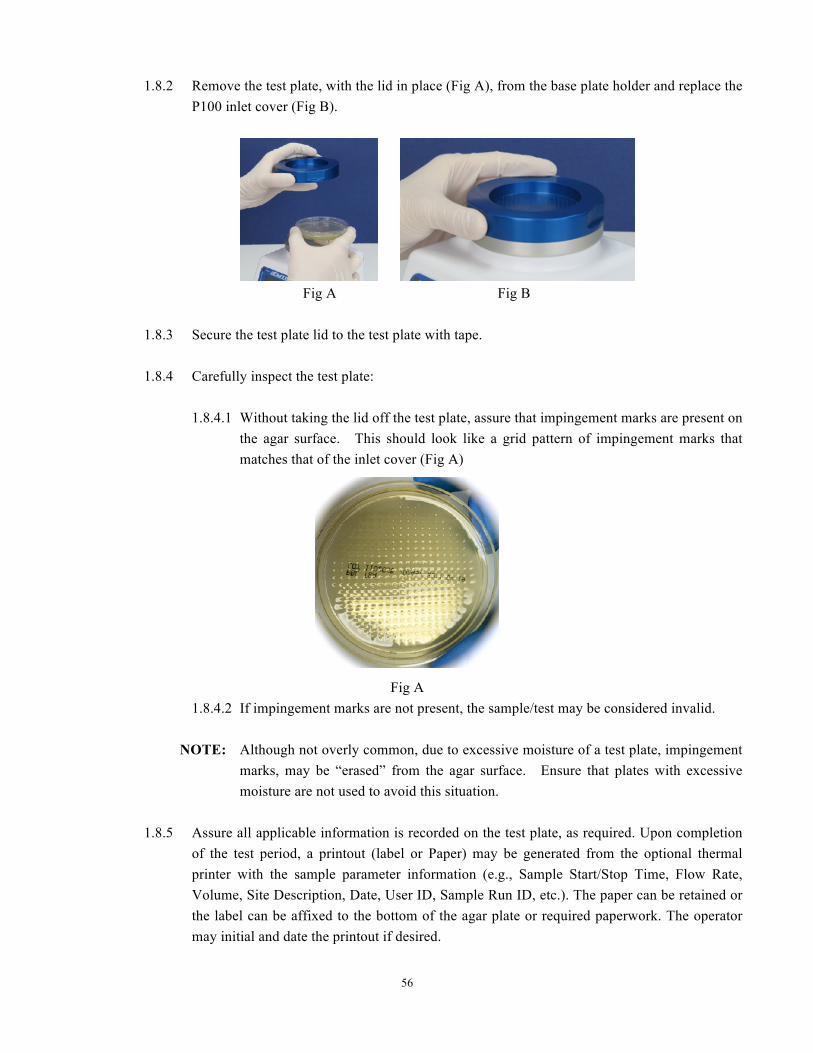
1.8.1 Remove the inlet cover by turning it counter clockwise to unlock it. Hold the inlet cover
above the test plate with one hand (Fig B), and with the other hand replace the lid of the test plate (Fig C). Be careful not to touch the inside of the lid or the agar surface. Do not move your hand over the exposed surface of the test plate. Allow the lid to lead your hand over the test plate as you replace it.
Fig A Fig B Fig C
56
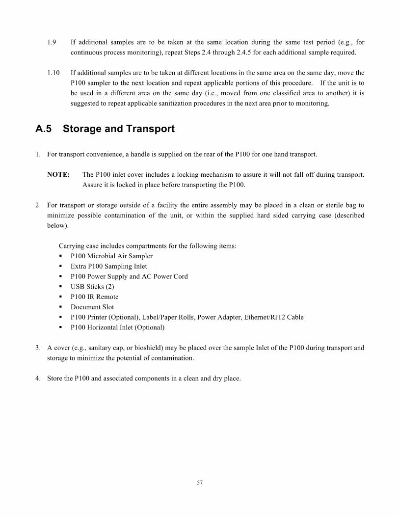
1.8.2 Remove the test plate, with the lid in place (Fig A), from the base plate holder and replace the
P100 inlet cover (Fig B).
Fig A Fig B
1.8.3 Secure the test plate lid to the test plate with tape.
1.8.4 Carefully inspect the test plate:
1.8.4.1 Without taking the lid off the test plate, assure that impingement marks are present on
the agar surface. This should look like a grid pattern of impingement marks that matches that of the inlet cover (Fig A)
Fig A 1.8.4.2 If impingement marks are not present, the sample/test may be considered invalid.
NOTE: Although not overly common, due to excessive moisture of a test plate, impingement
marks, may be “erased” from the agar surface. Ensure that plates with excessive moisture are not used to avoid this situation.
1.8.5 Assure all applicable information is recorded on the test plate, as required. Upon completion
of the test period, a printout (label or Paper) may be generated from the optional thermal printer with the sample parameter information (e.g., Sample Start/Stop Time, Flow Rate, Volume, Site Description, Date, User ID, Sample Run ID, etc.). The paper can be retained or the label can be affixed to the bottom of the agar plate or required paperwork. The operator may initial and date the printout if desired.
57
1.9 If additional samples are to be taken at the same location during the same test period (e.g., for
continuous process monitoring), repeat Steps 2.4 through 2.4.5 for each additional sample required.
1.10 If additional samples are to be taken at different locations in the same area on the same day, move the P100 sampler to the next location and repeat applicable portions of this procedure. If the unit is to be used in a different area on the same day (i.e., moved from one classified area to another) it is suggested to repeat applicable sanitization procedures in the next area prior to monitoring.
A.5 Storage and Transport 1. For transport convenience, a handle is supplied on the rear of the P100 for one hand transport.
NOTE: The P100 inlet cover includes a locking mechanism to assure it will not fall off during transport.
Assure it is locked in place before transporting the P100. 2. For transport or storage outside of a facility the entire assembly may be placed in a clean or sterile bag to
minimize possible contamination of the unit, or within the supplied hard sided carrying case (described below).
Carrying case includes compartments for the following items: § P100 Microbial Air Sampler § Extra P100 Sampling Inlet § P100 Power Supply and AC Power Cord § USB Sticks (2) § P100 IR Remote § Document Slot § P100 Printer (Optional), Label/Paper Rolls, Power Adapter, Ethernet/RJ12 Cable § P100 Horizontal Inlet (Optional)
3. A cover (e.g., sanitary cap, or bioshield) may be placed over the sample Inlet of the P100 during transport and
storage to minimize the potential of contamination. 4. Store the P100 and associated components in a clean and dry place.
58
Appendix B: Suggested P100 Sanitization Procedure
B.1 Materials
• Gloves (Sterile or Clean) • Low Particulate Shedding Wipes (e.g., Wipe All, Gamma Wipes) • Primary Disinfectants (e.g., Quaternary Ammonium Compounds) Important Note: Phenolic disinfectants should not be used on the P100 Enclosure, or touchscreen overlay, as it
will cause the components to become very brittle in a short period of use. • Secondary Disinfectants (e.g., 70% 0.2µm filtered or sterilized alcohol)
B.2 Sanitization Procedure
1. Don a pair of clean or sterile gloves
Note: Gloved hands should be sanitized with a disinfectant (e.g., 70% alcohol) throughout this procedure.
English DANGER: TO MINIMIZE THE CHANCE OF ELECTRIC SHOCK disconnect the P100 AC/DC power supply cord, and power off the unit during sanitization
DANGER: DO NOT SUBMERSE the P100 Air Sampler in any liquids! Français DANGER: AFIN DE RÉDUIRE LES RISQUES DE CHOC ÉLECTRIQUE débrancher le P100
Cordon d'alimentation AC / DC, et l'appareil hors tension pendant la désinfection
DANGER: NE PAS immerger le contrôleur de P100 Air Samplre dans tous les liquides!
2. P100 Sanitization:
2.1 To sanitize the P100, sanitize the exterior of the sampler, power supply and associated cables (if applicable), and IR Remote (if applicable), with a wipe saturated with disinfectant. It is ideal to wipe the components with a primary disinfectant (Quaternary Ammonium) followed by a secondary disinfectant (70% IPA, or Ethanol).
59
English WARNING: DO NOT DIRECTLY SPRAY THE P100 with any disinfectants, or other liquids!
Français ATTENTION: NE PAS pulvériser directement Le P100 avec les désinfectants ou d'autres liquides!
Important Note: Spraying the unit would potentially allow the disinfectant to enter into the Flow path, power and communications ports and damage these components, causing
it to fail. Note Importante: Pulvérisation de l'unité serait potentiellement permettre le désinfectant pour entrer
dans le Ports chemin d'écoulement, la puissance et de la communication et des dommages à ces composants, l'amenant à coup sûr.
3. P100 Inlet Cover Sanitization:
3.1 Remove the P100 Inlet Cover.
WARNING: Be careful not to saturate the air passageway opening located beneath the P100 adjustable media stage, as this would allow the disinfectant to be drawn into the flow pathway and flow control system and pose an electrical hazard, and damage to the unit. A plug is supplied for the blower inlet to minimize the chance of damaging the blower when sanitization is performed, as well as plugs for the USB and Ethernet ports.
ATTENTION: Veillez à ne pas saturer l'ouverture de passage d'air situé sous la scène médiatique P100 réglable, ce qui permettrait le désinfectant d'être aspiré dans la voie de circulation et le système de contrôle de flux et poser un risque de choc électrique et endommager l'appareil. Un bouchon est fourni pour l'entrée du ventilateur pour minimiser le risque d'endommagement de la soufflante lorsque la désinfection est effectuée, ainsi que des bouchons pour des ports Ethernet et USB.
3.1.1 The P100 inlet cover may be autoclaved prior to each days testing if desired, or chemically sanitized.
3.1.2 With a new saturated wipe, sanitize the interior surfaces of the inlet chamber, and media stage. 3.1.3 For chemical sanitization of the P100 Inlet Cover and Inlet Base, saturate a wipe with a primary
disinfectant (e.g., Quaternary Ammonium Compound) and wipe all surfaces of the inlet cover, inlet base, and media stage, allowing appropriate contact time. Wipe off residual disinfectant with a new wipe. The media stage may be threaded completely out so all surface of the chamber can be sanitized. Assure that the media stage retention spring is not removed.
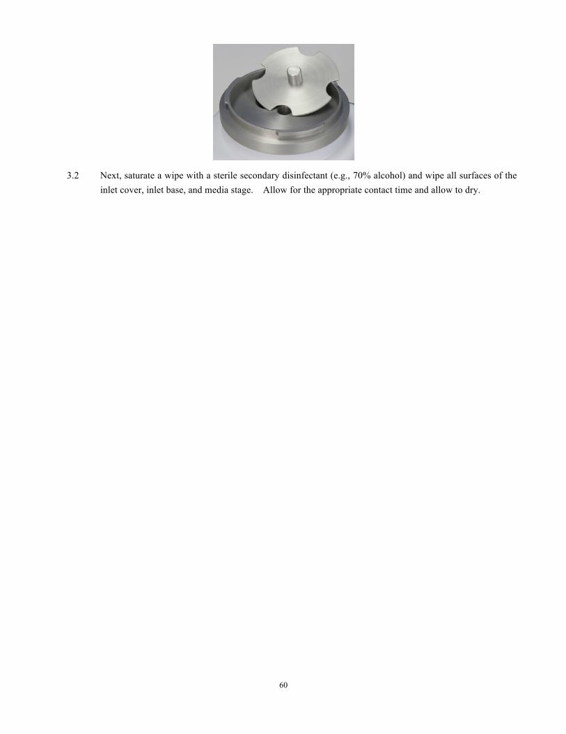
60
3.2 Next, saturate a wipe with a sterile secondary disinfectant (e.g., 70% alcohol) and wipe all surfaces of the inlet cover, inlet base, and media stage. Allow for the appropriate contact time and allow to dry.
61
Appendix C: Suggested Sample Submission and Results Recording
This section applies to all sampler types. 1. Submit the test plate(s) and test parameter information to the appropriate laboratory for recording and further testing. 2. Qualified personnel record the required test parameter information on the appropriate electronic or hard copy test report
form and place the test plates “On-Test” in incubation. 3. Incubate the test plates with an appropriate incubation scheme (e.g., 30-35°C for a minimum of 5-days [other incubation
requirements or schedules may be used as appropriate]). 4. Following the required incubation period, count all Colony Forming Units (CFU) found within the air impingement
zone. 5. Determine Total CFU/ Specified Volume and record the results in the appropriate section of the electronic or hard copy
test report form. This result is calculated as follows: Total CFU per Test Plate = CFU/ Identified Volume (L/ft3/m3) Volume Sampled
EXAMPLE:
If the test period was set to sample at 100 LPM for 10-minutes, the total volume collected would be 1000 Liters (L) or 1 cubic meter (m3). If following incubation, 20 CFU were recovered in the impingement zone of the plate. The calculation would be:
• Total CFU/Test Plate = 20 • Total Volume = 1000 L (or 1 m3)
20 CFU/Test Plate = 20 CFU = 0.02 CFU/L (or 20 CFU/m3 )
1000 L (or 1 m3) 1000 L (or 1 m3 ) 6. Record date “Off-Test” in the appropriate section of the test report form. 7. If Microbial Identification of organism recovered is required, submit plate for ID according to applicable procedures
related for sample submission and processing for Microbial Identification. Discard all other plates in an appropriate Bio-Hazard container for disposal.
8. Test Report Forms, once completed, should be reviewed for accuracy and completeness, and signed by a second
qualified analyst. NOTE: If Feller Calculations are required by your procedures, a Feller table follows. Please use at your discretion.
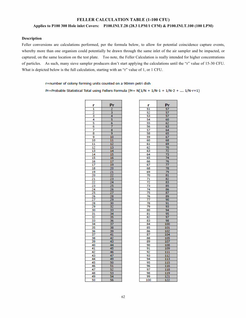
62
FELLER CALCULATION TABLE (1-100 CFU) Applies to P100 300 Hole inlet Covers: P100.INLT.28 (28.3 LPM/1 CFM) & P100.INLT.100 (100 LPM)
Description Feller conversions are calculations performed, per the formula below, to allow for potential coincidence capture events, whereby more than one organism could potentially be drawn through the same inlet of the air sampler and be impacted, or captured, on the same location on the test plate. Too note, the Feller Calculation is really intended for higher concentrations of particles. As such, many sieve sampler producers don’t start applying the calculations until the “r” value of 15-30 CFU. What is depicted below is the full calculation, starting with an “r” value of 1, or 1 CFU.

63
Appendix 1: CE Declaration of Conformity
64
Appendix 2: Two Year Warranty
Customer satisfaction is a prime objective of EMTEKEK, LLC ( EMTEK). Toward that objective, theproducts offered by EMTEK have been designed, manufactured and field tested with care and technicalcompetence.
(1) In any instance where an EMTEK instrument fails to perform to the customer’s satisfaction,it is EMTEK's policy to provide prompt and effective investigation of the situation.
(2) EMTEK warrants that products of its manufacture will perform according to stated specifications,and that the products will be free from defects in workmanship and materials, provided that thedefect of malperformance occurred under normal and proper use of the products. Decisionregarding such normal and proper use will be made by EMTEK following factory inspection andinvestigation of the application.
(3) Claims under the terms of this warranty must be submitted in writing within a period notnot exceeding 24 months following dateof shipment of the product from EMTEK to the purchaser, All products on which warranty claims are established must be submitted to EMTEK within the specifiedtime period to the EMTEK business address, unless otherwise specified by EMTEK in writing, withfreight transportation charges prepaid. Products judged by EMTEK to be defective will be repairedor replaced and returned to the customer, with return freight transportation charges prepaid by thecustomer.
(4) EMTEK reserves the right to disallow claims for warranty coverage in instances where there isevidence that the EMTEK product has been placed in a severe or corrosive atmosphere, outsidethe specified operating parameters specified for the product.
(5) Similarly, this warranty will be invalidated in instances where the malperformance is attributableto tampering or adjustment by other than factory approved personnel.
(6) EMTEK’s Liability under the terms of this warranty is limited to repair or replacement of defective ofproducts at no charge to the customer. EMTEK expressly disclaims any liability to its customers,sales representatives or users of its products, or to any other person or persons, for consequentialdamages of any kind arising out of or in any way connected with the use or EMTEK’s products.Representations and warranties made by any person, including sales representatives of EMTEK,which are inconsistent or in conflict with the terms of this warranty shall not be binding upon EMTEK,unless specifically stated in writing and approved as a document supplementary to this warranty byan authorized officer of the EMTEK organization.
EMTEK.WRNT.MAR.2010
Standard Two Year Warranty
TEL 303.682.3168 e-mail: [email protected] www.emtekair.com
EMTEK, LLC
Longmont, Colorado 80501 USA