![Sensor synaesthesia: touch in motion, and motion in touch · enhanced image deblurring [23]. Skinput [16] uses vibra-tory signals to infer the location of taps on one’s forearm.](https://static.fdocuments.in/doc/165x107/5ed823050fa3e705ec0de707/sensor-synaesthesia-touch-in-motion-and-motion-in-enhanced-image-deblurring-23.jpg)
EMoD: Efficient Motion Detection of Device-free …qian/papers/EMoD.pdf · tion. An RFID reader...
11
EMoD: Efficient Motion Detection of Device-free Objects Using Passive RFID Tags Kun Zhao * , Chen Qian § , Wei Xi * , Jisong Han * , Xue Liu † , Zhiping Jiang * , Jizhong Zhao * Xi’an Jiaotong University * University of Kentucky § McGill University † Abstract—Efficient and accurate tracking of device-free ob- jects is critical for anti-intrusion systems. Prior solutions for device-free object tracking are mainly based on costly sensing infrastructures, resulting in barriers to practical applications. In this paper, we propose an accurate and efficient motion detection system, named EMoD, to track device-free objects based on cheap passive RFID tags. EMoD is the first RFID system that can estimate the moving direction as well as the current location of a device-free object by measuring critical power variation sequences of passive tags. Compared with previous solutions, the unique advantage of EMoD, i.e., the capability to estimate moving directions, enables object tracking using a much sparser tag deployment. We contribute to both theory and practice of this phenomenon by presenting the interference model that precisely explains it and using extensive experiments to validate it. We design a practical EMoD based intrusion detection system and implement a prototype by commercial off-the-shelf (COTS) RFID reader and tags. The real-world experiments results show that EMoD is effective in tracking the trajectory of moving object various environments. Keywords-Device-free; Motion detection; Critical state; I. I NTRODUCTION Wireless sensing systems have been serving as a core com- ponent of critical infrastructures and industrial control systems recently. Typically, they are built upon sensors and control units for control and protection of a physical infrastructure. Real-time sensing plays an important role in combining the computational and physical worlds together for these industrial applications. One of the fundamental tasks of a wireless sensing system is to detect and track intruders to ensure the safety of lives and properties. Since intruders are uncooperative objects, they are impossible to be bound with specific devices. Therefore detection of device-free intruders is a core requirement of an automatic anti-intrusion system. Specific sensing devices, such as the passive infrared (PIR) sensors, sonic sensors, and video camera sensors have been used for device-free motion detection and tracking. However, these solutions incur significant cost concerns. Recently, Radio Frequency IDentification (RFID) has be- come a promising technique for device-free intrusion detec- tion. An RFID reader may observe and analyze signal changes of pre-deployed tags to infer the motion of an intruder. RFID- based motion detection is an attractive solution due to the con- venient and cost-efficient deployment of RFID tags in physical environments. In fact, RFID tags have been widely applied to identification and monitoring tasks in industrial control systems for applications already, including logistics, inventory, and retailing. Reusing the existing RFID infrastructure further saves the cost of a real-time motion detection system. However, existing RFID-based motion detection methods in the literature [1], [2], [3] are mostly based on active tags, which are less ubiquitous and much more expensive than passive tags. Existing passive tag based motion detection methods are device-based and not suitable for intrusion detec- tion [4], [5], [6]. Meanwhile, many of them require customized devices [7], [8], [9], [10] or specialized signals [11], [15]. To the best of our knowledge, the most recent device-free object tracking system using passive tags is Twins [16]. The idea of Twins are derived from the following observation. The mutual interference between two physical immediate readable tags caused by coupling effect will make one or both of them unreadable, which is called the critical state. The two coupled tags are named twins 1 . If one object moves around the twins, it will cause extra RF wave reflection to the tags such that unreadable tags may accumulate sufficient power, and thus be able to backscatter their responses. In this way, the Twins system can report a nearby motion via the state shift from unreadable to readable. In this work, we present an accurate and E fficient Mo tion D etection System for device-free objects using an infras- tructure constructed by passive tags, named EMoD. EMoD significantly improves Twins in the two following aspects. First, Twins can only tell the location of an object but does not provide the moving direction. EMoD is first method to report both location and direction information of a device-free object with passive RFID tags. With the direction information, the accuracy of inferred moving trajectory can be significantly improved. More specifically, since EMoD can infer trajectory through direction information, EMoD can draw the complete trajectory employing much fewer devices (including readers and antennas) than Twins’, which can dramatically reduce the deployment overheads. Second, the Twins system depends on a grid of passive tag pairs (twins) that fully cover the area of interest to localize device-free objects. In practice, the layout 1 We use “Twins” to refer to the overall motion detection system in [16] and “twins” to refer to the specific tag pair used in Twins.
-
Upload
truongdang -
Category
Documents
-
view
220 -
download
0
Transcript of EMoD: Efficient Motion Detection of Device-free …qian/papers/EMoD.pdf · tion. An RFID reader...

EMoD: Efficient Motion Detection of Device-freeObjects Using Passive RFID Tags
Kun Zhao∗, Chen Qian§, Wei Xi∗, Jisong Han∗, Xue Liu†, Zhiping Jiang∗, Jizhong Zhao∗
Xi’an Jiaotong University∗
University of Kentucky§
McGill University†
Abstract—Efficient and accurate tracking of device-free ob-jects is critical for anti-intrusion systems. Prior solutions fordevice-free object tracking are mainly based on costly sensinginfrastructures, resulting in barriers to practical applications. Inthis paper, we propose an accurate and efficient motion detectionsystem, named EMoD, to track device-free objects based on cheappassive RFID tags. EMoD is the first RFID system that canestimate the moving direction as well as the current locationof a device-free object by measuring critical power variationsequences of passive tags. Compared with previous solutions,the unique advantage of EMoD, i.e., the capability to estimatemoving directions, enables object tracking using a much sparsertag deployment. We contribute to both theory and practice of thisphenomenon by presenting the interference model that preciselyexplains it and using extensive experiments to validate it. Wedesign a practical EMoD based intrusion detection system andimplement a prototype by commercial off-the-shelf (COTS) RFIDreader and tags. The real-world experiments results show thatEMoD is effective in tracking the trajectory of moving objectvarious environments.
Keywords-Device-free; Motion detection; Critical state;
I. INTRODUCTION
Wireless sensing systems have been serving as a core com-ponent of critical infrastructures and industrial control systemsrecently. Typically, they are built upon sensors and controlunits for control and protection of a physical infrastructure.Real-time sensing plays an important role in combining thecomputational and physical worlds together for these industrialapplications.
One of the fundamental tasks of a wireless sensing systemis to detect and track intruders to ensure the safety of livesand properties. Since intruders are uncooperative objects, theyare impossible to be bound with specific devices. Thereforedetection of device-free intruders is a core requirement ofan automatic anti-intrusion system. Specific sensing devices,such as the passive infrared (PIR) sensors, sonic sensors,and video camera sensors have been used for device-freemotion detection and tracking. However, these solutions incursignificant cost concerns.
Recently, Radio Frequency IDentification (RFID) has be-come a promising technique for device-free intrusion detec-tion. An RFID reader may observe and analyze signal changesof pre-deployed tags to infer the motion of an intruder. RFID-based motion detection is an attractive solution due to the con-venient and cost-efficient deployment of RFID tags in physical
environments. In fact, RFID tags have been widely appliedto identification and monitoring tasks in industrial controlsystems for applications already, including logistics, inventory,and retailing. Reusing the existing RFID infrastructure furthersaves the cost of a real-time motion detection system.
However, existing RFID-based motion detection methodsin the literature [1], [2], [3] are mostly based on activetags, which are less ubiquitous and much more expensivethan passive tags. Existing passive tag based motion detectionmethods are device-based and not suitable for intrusion detec-tion [4], [5], [6]. Meanwhile, many of them require customizeddevices [7], [8], [9], [10] or specialized signals [11], [15].To the best of our knowledge, the most recent device-freeobject tracking system using passive tags is Twins [16]. Theidea of Twins are derived from the following observation. Themutual interference between two physical immediate readabletags caused by coupling effect will make one or both of themunreadable, which is called the critical state. The two coupledtags are named twins1. If one object moves around the twins,it will cause extra RF wave reflection to the tags such thatunreadable tags may accumulate sufficient power, and thusbe able to backscatter their responses. In this way, the Twinssystem can report a nearby motion via the state shift fromunreadable to readable.
In this work, we present an accurate and Efficient MotionDetection System for device-free objects using an infras-tructure constructed by passive tags, named EMoD. EMoDsignificantly improves Twins in the two following aspects.First, Twins can only tell the location of an object but doesnot provide the moving direction. EMoD is first method toreport both location and direction information of a device-freeobject with passive RFID tags. With the direction information,the accuracy of inferred moving trajectory can be significantlyimproved. More specifically, since EMoD can infer trajectorythrough direction information, EMoD can draw the completetrajectory employing much fewer devices (including readersand antennas) than Twins’, which can dramatically reduce thedeployment overheads. Second, the Twins system depends ona grid of passive tag pairs (twins) that fully cover the area ofinterest to localize device-free objects. In practice, the layout
1We use “Twins” to refer to the overall motion detection system in [16]and “twins” to refer to the specific tag pair used in Twins.
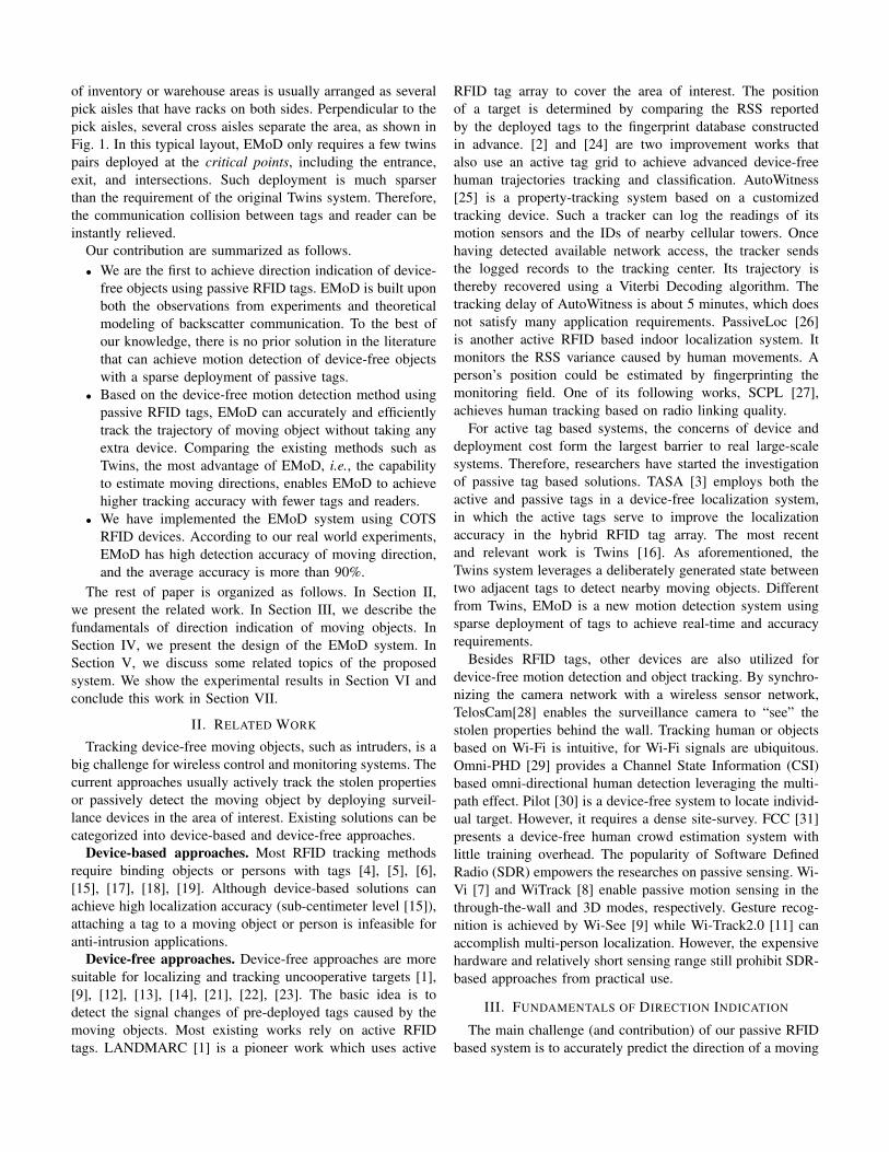
of inventory or warehouse areas is usually arranged as severalpick aisles that have racks on both sides. Perpendicular to thepick aisles, several cross aisles separate the area, as shown inFig. 1. In this typical layout, EMoD only requires a few twinspairs deployed at the critical points, including the entrance,exit, and intersections. Such deployment is much sparserthan the requirement of the original Twins system. Therefore,the communication collision between tags and reader can beinstantly relieved.
Our contribution are summarized as follows.• We are the first to achieve direction indication of device-
free objects using passive RFID tags. EMoD is built uponboth the observations from experiments and theoreticalmodeling of backscatter communication. To the best ofour knowledge, there is no prior solution in the literaturethat can achieve motion detection of device-free objectswith a sparse deployment of passive tags.
• Based on the device-free motion detection method usingpassive RFID tags, EMoD can accurately and efficientlytrack the trajectory of moving object without taking anyextra device. Comparing the existing methods such asTwins, the most advantage of EMoD, i.e., the capabilityto estimate moving directions, enables EMoD to achievehigher tracking accuracy with fewer tags and readers.
• We have implemented the EMoD system using COTSRFID devices. According to our real world experiments,EMoD has high detection accuracy of moving direction,and the average accuracy is more than 90%.
The rest of paper is organized as follows. In Section II,we present the related work. In Section III, we describe thefundamentals of direction indication of moving objects. InSection IV, we present the design of the EMoD system. InSection V, we discuss some related topics of the proposedsystem. We show the experimental results in Section VI andconclude this work in Section VII.
II. RELATED WORK
Tracking device-free moving objects, such as intruders, is abig challenge for wireless control and monitoring systems. Thecurrent approaches usually actively track the stolen propertiesor passively detect the moving object by deploying surveil-lance devices in the area of interest. Existing solutions can becategorized into device-based and device-free approaches.
Device-based approaches. Most RFID tracking methodsrequire binding objects or persons with tags [4], [5], [6],[15], [17], [18], [19]. Although device-based solutions canachieve high localization accuracy (sub-centimeter level [15]),attaching a tag to a moving object or person is infeasible foranti-intrusion applications.
Device-free approaches. Device-free approaches are moresuitable for localizing and tracking uncooperative targets [1],[9], [12], [13], [14], [21], [22], [23]. The basic idea is todetect the signal changes of pre-deployed tags caused by themoving objects. Most existing works rely on active RFIDtags. LANDMARC [1] is a pioneer work which uses active
RFID tag array to cover the area of interest. The positionof a target is determined by comparing the RSS reportedby the deployed tags to the fingerprint database constructedin advance. [2] and [24] are two improvement works thatalso use an active tag grid to achieve advanced device-freehuman trajectories tracking and classification. AutoWitness[25] is a property-tracking system based on a customizedtracking device. Such a tracker can log the readings of itsmotion sensors and the IDs of nearby cellular towers. Oncehaving detected available network access, the tracker sendsthe logged records to the tracking center. Its trajectory isthereby recovered using a Viterbi Decoding algorithm. Thetracking delay of AutoWitness is about 5 minutes, which doesnot satisfy many application requirements. PassiveLoc [26]is another active RFID based indoor localization system. Itmonitors the RSS variance caused by human movements. Aperson’s position could be estimated by fingerprinting themonitoring field. One of its following works, SCPL [27],achieves human tracking based on radio linking quality.
For active tag based systems, the concerns of device anddeployment cost form the largest barrier to real large-scalesystems. Therefore, researchers have started the investigationof passive tag based solutions. TASA [3] employs both theactive and passive tags in a device-free localization system,in which the active tags serve to improve the localizationaccuracy in the hybrid RFID tag array. The most recentand relevant work is Twins [16]. As aforementioned, theTwins system leverages a deliberately generated state betweentwo adjacent tags to detect nearby moving objects. Differentfrom Twins, EMoD is a new motion detection system usingsparse deployment of tags to achieve real-time and accuracyrequirements.
Besides RFID tags, other devices are also utilized fordevice-free motion detection and object tracking. By synchro-nizing the camera network with a wireless sensor network,TelosCam[28] enables the surveillance camera to “see” thestolen properties behind the wall. Tracking human or objectsbased on Wi-Fi is intuitive, for Wi-Fi signals are ubiquitous.Omni-PHD [29] provides a Channel State Information (CSI)based omni-directional human detection leveraging the multi-path effect. Pilot [30] is a device-free system to locate individ-ual target. However, it requires a dense site-survey. FCC [31]presents a device-free human crowd estimation system withlittle training overhead. The popularity of Software DefinedRadio (SDR) empowers the researches on passive sensing. Wi-Vi [7] and WiTrack [8] enable passive motion sensing in thethrough-the-wall and 3D modes, respectively. Gesture recog-nition is achieved by Wi-See [9] while Wi-Track2.0 [11] canaccomplish multi-person localization. However, the expensivehardware and relatively short sensing range still prohibit SDR-based approaches from practical use.
III. FUNDAMENTALS OF DIRECTION INDICATION
The main challenge (and contribution) of our passive RFIDbased system is to accurately predict the direction of a moving

Fig. 1. Deployment scenario
object in real-time. Addressing this issue significantly reducesthe deployment cost and increases detection efficiency.
The fundamentals of the proposed direction indication algo-rithm is based upon both the observations from experimentsand theoretical modeling of backscatter communication. Wesummarize our findings as follows.
• We define the critical power (CP) of a tag as the power ofthe transmission (reader) with which the tag can be turnedinto its critical state. For per-location of an intruder,monotonic relationship between the CP of deployed tagsand the position of the object does not hold.
• However, for whole-trajectory in each monitoring inter-section, a unique correspondence between the features ofCP sequence and trajectory holds well, i.e., the distribu-tion of the CP matrix can be used as an indicator forplotting an intruder’s trajectory.
In the following subsections, we detail the theoretical anal-ysis supporting the above claims, and present the verificationresult of indoor experiments.
A. Impact of object location to received power
Utilizing the electric field intensity, we establish the func-tional relationship between the average power density and theobject’s location.
A tag’s average power density is determined by the electricfield intensity. According to the Poynting theorem [32], thetime-average power density 〈S〉 at position z can be calculatedas:
〈S〉 =1
2ηE2z (1)
where Ez is the norm of electric filed intensity at z, andη =
√µε ≈ 120πΩ is the intrinsic impedance of free space.
Furthermore, the electric filed intensity is determined by thelocation of moving object’s in a stationary environment.
The wireless channel between the transmitter antenna andreceiver antenna can be modeled as a linear time-varying(LTV) system [32]. In a stationary environment, i.e., the an-tenna and tags are fixed, the electric intensity can be separatedinto two parts: the stable environmental effect and the movingobject’s effect. We describe the stable (non-person) scenarioat first, and then superimpose the moving object’s influence.
1) Environmental effect: Assuming the reader’s transmitintensity is ER, the received intensity of the tag in a stable
scenario EST can be denoted as
EST = ER
m∑i=0
ΓiLRTi cos(ωt− ϕi)
where m, Γi, LRTi, ϕi are the number of distinguishable paths,
the reflections of obstacles’ surface along the ith path, thepath loss of the ith path from the reader to the tag, and thecorresponding phase delay, respectively.
According to the phasor formula [33], we have
EST = ERART cos(ωt− ϕRT ) (2)
and
ART =
(m∑i=0
ΓiLRTicosϕi
)2
+
(m∑i=0
ΓiLRTisinϕi
)2
ϕRT = arctan
m∑i=0
ΓiLRTisinϕi
m∑i=0
ΓiLRTicosϕi
where ART and ϕRT denote the path loss and phase delaycontributed by all multipath components, respectively.
2) Moving object effect: When an object P enters intothis area, it changes the electromagnetic field distribution. Theintensity contributed by the moving object [32] is
EPT = ERAP cos(ωt− ϕP )
where AP and ϕP denote the path loss and phase delaycontributed by the intrusive object.
Due to the linearity of LTV, the joint intensity ET can becalculated as
ET = EST + EP
T (3)
= ER(ART cos(ωt− ϕRT ) + AP cos(ωt− ϕP ))
Using the phasor formula again and substituting (3) into (1),we have
〈S〉 =1
2ηE2T
=1
2ηE2R
(A2P + 2APART
· cos(ϕP − ϕRT ) + A2RT
)(4)
Assuming the coordinates of the reader, tag and object areR = (XR, YR), T = (XT , YT ) and P = (XP , YP ), respec-tively, the length of trajectory RPT from the reader to the tagvia the object is dRPT =
√(XP −XR)2 + (YP − YR)2 +√
(XT −XP )2 + (YT − YP )2.The path loss on PRT can be modeled as
AP =αΓPdRPT
(5)
where α is a proportionality constant [33]. Due to the half-wave loss phenomenon [32], the equivalent phase delay is
ϕP = 2πdRPTλ− π (6)

Therefore, we can see that the average power density of tag〈S〉 is determined by the transmitting power density E2
R
2η ,environmental parameters ART and ϕRT , and the locationbased parameters AP and ϕP . The last two parameters arecorrelated with the moving object’s position, as shown in (5)and (6). In other words, if the environment remains unchanged,the received power of the tag is only determined by the object’slocation, i.e.,
〈S〉 = f(AP , ϕP ) = f(P )
It is worth to note that a power density 〈S〉 is not one-to-onecorrelated to a unique location P , due to the non-monotonicrelationship shown in (4). Thus, we are aiming to extracta power sequence uniquely mapping to the moving target’strajectory.
B. Weak correlation between trajectory and power sequence
Denote the moving target’s trajectory and the correspond-ing power sequence as T = 〈t1, t2, · · · , tm〉 and S =〈s1, s2, · · · , sm〉 = 〈f(t1), f(t2), · · · , f(tm)〉, respectively.Theoretically, same trajectories should have same power se-quences. Due to the fading and noise, the measured powersequences, however, are not always the same, when the objectmoves along the same trajectory. There are two main reasonsincurring this phenomenon:
1) Training samples cannot exactly follow the same po-sition ti of the trajectory, so there is an error at eachtrajectory position. We name such an error as a positionbased error (PBE), and exploit the discretization andmorphological opening operation to solve this problem.
2) When an intruder enters an area under surveillance, thefirst trajectory position might be t2 or t3, but not t1. Inother words, the trajectory sequences are mismatched,and need to be aligned. We name this kind of errorsas the initial bias (IB), and exploit the morphologicaldilation to solve this problem.
These two problems make it difficult to directly estimatethe trajectory according to the power sequence. We solve themusing the mathematical morphology, which will be detailed inSection IV.
C. Experimental validation for theoretic analysis
We conduct indoor experiments to verify the propertiesderived from the theoretical analysis. Fig. 2 shows an exampleof CP sequences with different trajectories. There are threetwins deployed in the intersection as shown in Fig. 1. Thecolored map denotes the time sequence from the first sampleto 200th sample. Three axes denote the CP values of threetwins. Subfigures (a) and (d) with circles show the CP dis-tributions of two turning-left experiments. Subfigure (b) withlower-triangular shows the CP distribution of going-straightwhile subfigure (c) with upper-triangular shows the resultsof turning-right, respectively. Obviously, different trajectorieshave different CP distributions, while the same trajectorieshave similar CP distributions with some inconsistent values.
2224
2624
2622
24
26
2224
2624
26
22
24
26
2426
2224
26
22
24
26
2224
2624
2622
24
26
20
40
60
80
100
120
140
160
180
200
Fig. 2. CP variance with different moving trajectories
Hence, collecting such sequences and extracting their fea-tures is possible to identify the motion direction of objects.This heuristic correlation has not been disclosed by priorworks, because they merely provide a “0/1” judgment toindicate whether the object is detected or not, resulting in adegradation in both the accuracy and efficiency.
IV. SYSTEM DESIGN
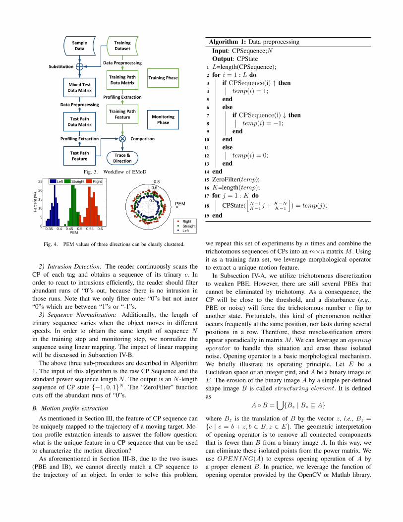
Based on the theoretical analysis and experimental resultspresented in Section III, we propose a device-free method torecognize and predict an intruder’s movement direction. Asshown in Fig. 3, our algorithm consists of three phases, 1) datapreprocessing, 2) motion profile extraction, and 3) trajectoryrecognition.
A. Data preprocessing
The data preprocessing phase achieves three functions: PBEelimination, intrusion detection, and sequence normalization.
1) PBE Elimination: As stated in Section III-B, in the PBEelimination step, we need to remove the impacts of PBE. If theobject moves along the same trajectory, the variance of powersequence caused by PBE is ∆si ≈ ∆ti
dfdt |t=ti . It can be
deduced by casting the 1st order Taylor formula to (4). Since∆ti is much less than the length of the trajectory, ∆si is muchless than the power variation. Therefore, by setting reasonablethreshold parameters, we can discretize the power into atrichotomous number c (i.e., 1, 0,−1), which represents theincrease, stableness, and decrease of the tag’s CP, respectively.As mentioned in Section III, objects at different locations willhave different effects on the tag’s CP. In some locations, theobject reflects RF signals, which will inject more RF wavesto the tag such that it can be read with a smaller CP, wherec = 1. In some locations, the object blocks the transmissionfrom the reader to tag, weakening the power received by thetag such that it should be read with a larger CP, where c = −1.In the other locations, the object has little impact on the tag’sCP, where c = 0.
Training Path Feature
Profiling Extraction
Training Phase
Monitoring Phase
Sample Data
Training Dataset
Training Path Data Matrix
Data Preprocessing
Test Path Data Matrix
Data Preprocessing
Test Path Feature
Profiling Extraction
Trace & Direction
Comparison
Substitution
Mixed Test Data Matrix
Fig. 3. Workflow of EMoD
0.35 0.4 0.45 0.5 0.55 0.60
5
10
15
20
25
PEM
Per
cent
(%
)
Left Straight Right
0.6 0.8
0.2
RightStraightLeft
PEM
Fig. 4. PEM values of three directions can be clearly clustered.
2) Intrusion Detection: The reader continuously scans theCP of each tag and obtains a sequence of its trinary c. Inorder to react to intrusions efficiently, the reader should filterabundant runs of “0”s out, because there is no intrusion inthose runs. Note that we only filter outer “0”s but not inner“0”s which are between “1”s or “-1”s.
3) Sequence Normalization: Additionally, the length oftrinary sequence varies when the object moves in differentspeeds. In order to obtain the same length of sequence Nin the training step and monitoring step, we normalize thesequence using linear mapping. The impact of linear mappingwill be discussed in Subsection IV-B.
The above three sub-procedures are described in Algorithm1. The input of this algorithm is the raw CP Sequence and thestandard power sequence length N . The output is an N -lengthsequence of CP state −1, 0, 1N . The “ZeroFilter” functioncuts off the abundant runs of “0”s.
B. Motion profile extraction
As mentioned in Section III, the feature of CP sequence canbe uniquely mapped to the trajectory of a moving target. Mo-tion profile extraction intends to answer the follow question:what is the unique feature in a CP sequence that can be usedto characterize the motion direction?
As aforementioned in Section III-B, due to the two issues(PBE and IB), we cannot directly match a CP sequence tothe trajectory of an object. In order to solve this problem,
Algorithm 1: Data preprocessingInput: CPSequence;NOutput: CPState
1 L=length(CPSequence);2 for i = 1 : L do3 if CPSequence(i) ↑ then4 temp(i) = 1;5 end6 else7 if CPSequence(i) ↓ then8 temp(i) = −1;9 end
10 end11 else12 temp(i) = 0;13 end14 end15 ZeroFilter(temp);16 K=length(temp);17 for j = 1 : K do18 CPState(
[N−1K−1j + K−N
K−1
]) = temp(j);
19 end
we repeat this set of experiments by n times and combine thetrichotomous sequences of CPs into an m×n matrix M . Usingit as a training data set, we leverage morphological operatorto extract a unique motion feature.
In Subsection IV-A, we utilize trichotomous discretizationto weaken PBE. However, there are still several PBEs thatcannot be eliminated by trichotomy. As a consequence, theCP will be close to the threshold, and a disturbance (e.g.,PBE or noise) will force the trichotomous number c flip toanother state. Fortunately, this kind of phenomenon neitheroccurs frequently at the same position, nor lasts during severalpositions in a row. Therefore, these misclassification errorsappear sporadically in matrix M . We can leverage an openingoperator to handle this situation and erase these isolatednoise. Opening operator is a basic morphological mechanism.We briefly illustrate its operating principle. Let E be aEuclidean space or an integer gird, and A be a binary image ofE. The erosion of the binary image A by a simple per-definedshape image B is called structuring element. It is definedas
A B =⋃Bz | Bz ⊆ A
where Bz is the translation of B by the vector z, i.e., Bz =c | c = b + z, b ∈ B, z ∈ E. The geometric interpretationof opening operator is to remove all connected componentsthat is fewer than B from a binary image A. In this way, wecan eliminate these isolated points from the power matrix. Weuse OPENING(A) to express opening operation of A bya proper element B. In practice, we leverage the function ofopening operator provided by the OpenCV or Matlab library.

In this way, we solve the PBE problem by discretization andthe opening operation.
To solve the IB problem, we exploit the dilation, whichis another fundamental morphological operator defined asfollowing:
A⊕B = z | z ∈ E, (Bs)z ∩A 6= ∅
where Bs denotes the symmetric of B, i.e., Bs = b | −b ∈B. The dilation operation probes and expands the shapescontained in the input image A using a structuring element B.The function of dilation operator can also be found in existingscientific computing tools. We use DILATE(A) to expressdilating operation of A by a proper element B.
Consider the CP state matrix M , whose element sji = cmeans the CP of the ith site in the jth experiment is c. Sincethe dilation has shift invariance, if we dilate two row vectorssi and sj , the more overlapping areas we have, the bettercompatibility between these two vectors can be achieved, orvice versa. Therefore, we propose a metric PEM, i.e., thepercentage of nonzero elements in the dilated CP state MatrixM , and use the difference of PEM (DPEM) to detect the mostconsistence vectors of the CP state vectors. It has three mainsteps: 1) calculating the PEM of initial CP state matrix Mand saving it as PEM ; 2) replacing the ith row of M byeach test vector in turn, calculating the new PEM of replacedmatrix M ′, and saving it as Pem(i) ; and 3) calculating theminimum DPEM by DPEM = ||Pem(i) − PEM ||. Wepropose Theorem 1 as follows to show that test vectors haveno impact on the dilation result of those non-replaced parts.That can also explain that why we can test the PEM row byrow.
Theorem 1: if A =⋃Ai, A⊕B =
⋃(Ai ⊕B)
Proof:
A⊕B = z | z ∈ E, (Bs)z ∩A 6= ∅= z | z ∈ E, (Bs)z ∩ (
⋃Ai) 6= ∅
= z | z ∈ E,⋃
((Bs)z ∩Ai) 6= ∅
=⋃
(z | z ∈ E, (Bs)z ∩Ai 6= ∅)
=⋃
(Ai ⊕B)
Fig. 4 leverages both bars and polar graphs to show thedistribution of PEM values for three movement trajectories.It is very clear that PEM values of different movementtrajectories are clustered, implying that PEM is a good metricfor trajectory classification and recognition.
C. Trajectory recognition
In the training step, we repeat the measurement of thetrichotomous sequence Sij for each kind of the movementtrajectory Tj by N times, and then extract PEM P(j) fortrajectory Tj by performing dilations (see Algorithm 2).
In the monitoring step, we can obtain a trichotomoussequence St. In order to identify the actual movement tra-jectory, we replace each Sij with St to obtain the motionprofile P (i, j), and then calculate the DPEM between P(j)and P (i, j). For each Tj , we can get a motion profileDPEM(j) =| P(j) − P (i, j) |. The trajectory Tj with thesmallest DPEM is the actual movement trace.
Algorithm 2: Profiling extraction and path identificationInput: S, testV ectorOutput: path
1 [U, V,N ] = size(S);2 if in Training Phase then3 for j = 1 : U do4 OPENING(S(j, :, :));5 P(j) = DILATE(S(j, :, :));6 end7 end8 else9 for i = 1 : V do
10 S(:, i, :) = testV ector;11 for j = 1 : U do12 OPENING(S(j, :, :));13 P (i, j) = DILATE(S(j, :, :));14 end15 end16 path = arg
jmin| P(j)− P (i, j) |;
17 end
V. IMPLEMENTATION AND DEPLOYMENT ISSUES
A. Detection rate and deployment density
In this subsection, we discuss the efficiency of our methodcompared with the conventional method that is not supportingthe direction recognition.
For the ease of presentation, direction recognition can beconverted to a problem: how to capture a message overa percolation modeled graph [34]. Suppose a packet K ispropagated in an undirected graph G(V,E). In each timeperiod, the packet can move from one vertex Va to one ofits neighboring vertices Vb. During the packet’s probing, thevertices that can report whether they receive the packet arecalled probe vertices, while the rest vertices are defined as theordinary vertices.
Suppose the percentage of intersections (vertices) that anintruder (packet) passes is s and the deployment density, i.e.,the percentage of probe vertices, is α. We present our empiricalresults on the relationship between α and the detection ratio γin Fig. 12. We find that if s > 10%, more than 90% of eventscan be detected with only 20% deployments.
Furthermore, if we deploy EMod at more intersections suchthat if the α → 100%, the probability that we can track thecomplete trajectory of a given packet tends to 1. On the otherhand, if the number of “twins” is inadequate, i.e., a small α

that cannot guarantee to capture any given packet in the graph,it is impossible to track the complete trajectory. Therefore, wepursue the optimal setting of α.
There are two conclusions which are useful for solving thisproblem, guaranteed by percolation theory [34]. Denote theθ(α) as the probability that we can obtain the whole trajectoryof an intruder from the entrance to the exit in graph G, thenwe have
1) θ(α) = 0 if α < 1/3;2) If G is a 2D square grid, α = 0.5927 is the inflection
point of θ, i.e., d2θdα2 |α=0.5927 = 0.
The above conclusions indicate that, if α < 1/3, the intruderis almost impossible to be completely tracked. In other words,if we attempt to identify the entire trajectory of the intruder,the deployment density should not be less than 1/3.
If α is around 0.5927, the θ(α) grows most rapidly. In fact,when α is around 0.5927, the growth rate of θ is proportionalto (α − 0.5927)−1. As a result, more than 80% trajectoriescan be completely detected when α ≥ 0.7.
For the motion detection approach with direction recogni-tion, the detection rate (the probability of detecting the movingobject at least once) in one intersection is related to theprevious intersection whether the motion has been detected,which can be formulated as:
Prneighbor(v)t+1 = T |vt = T
Assume that the percentage of probe vertices is β. For thefirst movement from the start vertex, the detection rate of Kis β, and the missing rate is 1 − β. For each vertex at thetrajectory of K, if K in the current vertex is detected witha probability β, it will be detected in the successor vertexwith 100% probability. If the previous vertex along the K’strajectory does not detect K, which is with a probability 1−β,its detection rate in the successor vertex is β. The detection rateof K in the vertex along the trajectory is β× 1 + (1− β)β =2β − β2 except for the first vertex, and the missing rate is1− (2β − β2) = (1− β)2.
In order to obtain the same detection rate using a motion de-tection approach without direction recognition, e.g., Twins[16],we set 2β − β2 = α. Then we have β = 0.362. Compared tothe value of α = 0.7, we can find that the number of “twins”like detectors required for completely detecting the intruder’strajectory, i.e., the deployment overhead, is cut in half if usingEMoD. In other words, EMoD is able to significantly reducethe deployment overhead compared with the non-direction-recognition method.
Note that both Twins and EMoD can be applied to intrusiondetection. Twins focuses on checking whether an intrusionoccurs in the area of interests, while EMoD can further sketchthe intruder’s trajectory by leveraging physical layout of thearea. As such, EMoD is more suitable for the warehouseor retailing scenarios, which usually contain multiple-rowshelves. We detail the performance comparison of these twoapproach at tracking scenario in Section VI-H.
B. Multipath effects
As aforementioned, most existing device-free approachesutilize the Radio Signal Strength (RSS) variation to detec-t intruders. In RFID systems, RSS is measured using thereceived power of RF waves backscattered from a tag. Forpassive RFID tags, the RSS value varies sharply upon theambient changes in the backscatter communications, includingthe disturbance caused by intruders. However, the receivedwave is the one overlapped by the waves coming from alldirections, due to the refection, diffraction, and scatteringcaused by the furniture, people, and other obstacles. This effectis known as multipath propagation. Upon this effect, the RSSvariation cannot accurately reflect the intrusion, because evenif there is no any intruder, the RSS value may still changearbitrarily, incurring false alarms or missing reports to thedetection result.
EMoD leverages the critical state to eliminate the impactfrom multipath effects. In Twins [16], the authors proposeto use the critical state for intrusion detection, which is alsoutilized by EMoD. Instead of the RSS variation, critical state isable to suppress noise interference. The key insight of criticalstate can be presented as follows. If two tags are placed withina certain distance, one or both of them become unreadabledue to their mutual interference. Keeping the pair of tags insuch a state, if an object or human being moves around thetags, some RF waves will be reflected or refracted to the tags,similar to the multipath effect. In this case, the unreadabletag(s) can receive sufficient energy to break the critical stateand then become readable, which is called as a state jumping.Clearly, such a “0/1” judgment mechanism will reliably reportthe motion nearby, avoiding the impact from ambient noises.
C. Real-time requirement
The strict real-time requirement for intruder detection posesanother challenge to EMoD. When forcing the tags into criticalstate for checking whether tags experiences a state shift,a reader should switch the power setting to the predefinedCP of each tag. It is very time-consuming for commercialreaders to switch their powers among multiple CPs of differenttags. For example, switching to a specific power setting takes0.02s to 0.08s for Impinj reader R220. In the real world,CPs of tags distribute diversely within a wide range, due tothe manufacture variation. Note that different locations yielddifferent transmission paths, also leading variant CPs to tags.Hence, it is common that the reader switches its power overa big gap of CPs. As a result, scanning all tags with theirCPs will continue several seconds, which can hardly meet thereal-time requirement of intrusion detection, considering theintruder may quickly pass the intersections.
EMoD achieves a prompt scanning on the CP samples byadjusting the critical power of tags within a small range. Thiscan be achieved by changing the distance between two tags ina pair of twins [16]. We can probe proper distance betweentwo tags in the twins such that the CPs of all tag pairs (twins)are within a small range, which allows the reader to poll the

scanning on the twins in a very short time duration, e.g. merely< 50 ms in our experiments.
Furthermore, we can promote the real-time performanceby significantly decreasing the number of tags. According toSlotted ALOHA protocol, which is the mainstream industrialstandard for passive RFID tags, the average packet delay
D = 0.5 + eG + (eG − 1)B (7)
where G is the offered load (packets per unit time) and B is theaverage collision delay, respectively. Since EMoD uses muchfewer tags than Twins does, the flux of EMoD is much smallerthan that of Twins, i.e., GEMoD GTwins. Substituting to(7), DEMoD DTwins, i.e., the packet delay of EMoD ismuch smaller than that of Twins. In this way, we can promotethe real-time performance by decreasing transmitting delay.
D. Particle filter based Realtime Tracking
Once capturing the motion direction at each monitoredintersection, it is easy to track the trajectory of the objectas time varies. Here we introduce an improved particle filterto track the object. The overview of the algorithm is shownas following:
Initially, the object is located in the intersection (x0, y0)where he is detected at the first time. At each time step,the location set is updated based on possible movements andnew observations. In our experiments, we assume locationsare (x, y) positions in two dimensional Cartesian space.
In the prediction step, we start from the set of possiblelocations computed in the previous step, Lt−1, and applythe mobility model to each sample for getting a set of newsamples, Lt. If in previous step lit−1 is one possible positionof an object, the possible current positions are containedin the circular region whose origin is lit−1 and radius isvmax. We use d(l1, l2) to denote the Manhattan distanced(lt−1, lt) = ||lt−1 − lt||1 between two points l1 and l2.
p(lt|lt−1) =
1
d(lt−1,lt)if d(lt, lt−1) < vmax
0 if d(lt, lt−1) ≥ vmax(8)
In the cases where the object is detected again at themonitored intersection, the probability distribution can beadjusted for achieving better predictions.
In the filtering step, we filter those impossible locations outbased on new observations. We only rely on direct informationretrieved from monitored intersections. Let S denote the setof all monitored intersections, r denote the detection range.The filter condition of location l isfilter(l) = ∀s ∈ S, d(l, s) < r
After filtering, the number of possible locations may besmaller than N . In this case, the prediction and filteringprocesses repeat and union the possible points found, untilat least N possible locations can be acquired. After this step,the tracking accuracy will be significantly improved.
Fig. 5. Three experimental environments: Library, Office, and Exhibitionhall
VI. EXPERIMENTAL EVALUATIONS
A. Experimental setup
We conduct real experiments in a 28 m × 15 m indoor areato evaluate the performance of EMoD. We implement EMoDusing three types of commodity passive tags, i.e., Impinj E41-b, E41-c, and Alien 964x, a number of commercial passive R-FID readers model Impinj SPEEDWAY 220, and off-the-shelfcircularly polarized antenna model Laird A9028R30NF. Thesepassive tags have been widely employed in existing logisticsand inventory systems. The reader and antenna operate withina spectrum of transmission power from 10 dBm to 32.5 dBm,and a frequency ranging from 920 MHz to 928 MHz. The gainof the antenna is 8 dBi.
The EMoD system operates in three phases, the deployingphase, the learning phase and the monitoring phase. In thedeploying phase, we deploy EMoD as shown in Fig. 1. Thereader is deployed at one corner of the intersection, e.g., at thepoint R. Three groups of twins are tightly attached to shelvesat other three corners. Hence, slight vibrations will not changethe critical power and influence the detection results of EMoD.On the other hand the tags are displaced, e.g., the tags movea short distance due to the shelf displacement, their criticalpower will change to a new level. However, EMoD identifiesthe direction of moving objects based on the sequence of tags’critical power changes instead of tags’ critical power readings.Thus, the slight displacement of twins will not influence thedirection detection.
In the learning phase, we invite 10 volunteers with differentgenders and body shapes to participate our experiments. Eachvolunteer moves 10 times from the start point A to each ofthree destination points, i.e., B, C, and D, to act as turning-left, going-straight, and turning-right, respectively. Volunteersare required to pass through the intersection with normal speed(about 1.5m/s). Therefore, we can obtain the corresponding CPsequences. We set the standard sequence length N as the mode(the most common value among this group) of sequence lengthand resize other sequences length into N by linear mapping.
Detection accuracy70% 80% 90% 100%
CD
F
0%
20%
40%
60%
80%
100%-10°
-5°
0°
5°
10°
Fig. 6. Impact of angle between reader and tags
Detection accuracy70% 80% 90% 100%
CD
F
0%
20%
40%
60%
80%
100%1.4-1.6m1.0-1.2m0.6-0.8m
Fig. 7. Impact of tag height
Detection accuracy70% 80% 90% 100%
CD
F
0%
20%
40%
60%
80%
100%0.8m1.2m1.6m
Fig. 8. Impact of intersection width
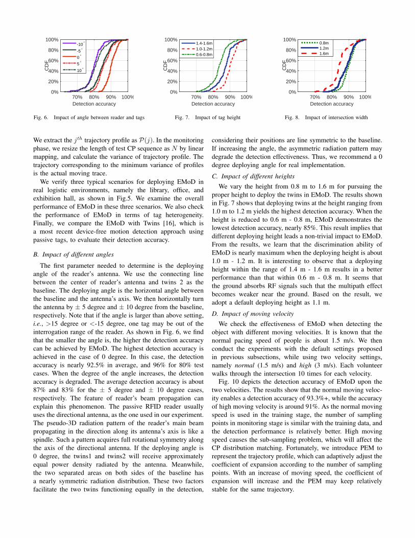
We extract the jth trajectory profile as P(j). In the monitoringphase, we resize the length of test CP sequence as N by linearmapping, and calculate the variance of trajectory profile. Thetrajectory corresponding to the minimum variance of profilesis the actual moving trace.
We verify three typical scenarios for deploying EMoD inreal logistic environments, namely the library, office, andexhibition hall, as shown in Fig.5. We examine the overallperformance of EMoD in these three scenarios. We also checkthe performance of EMoD in terms of tag heterogeneity.Finally, we compare the EMoD with Twins [16], which isa most recent device-free motion detection approach usingpassive tags, to evaluate their detection accuracy.
B. Impact of different angles
The first parameter needed to determine is the deployingangle of the reader’s antenna. We use the connecting linebetween the center of reader’s antenna and twins 2 as thebaseline. The deploying angle is the horizontal angle betweenthe baseline and the antenna’s axis. We then horizontally turnthe antenna by ± 5 degree and ± 10 degree from the baseline,respectively. Note that if the angle is larger than above setting,i.e., >15 degree or <-15 degree, one tag may be out of theinterrogation range of the reader. As shown in Fig. 6, we findthat the smaller the angle is, the higher the detection accuracycan be achieved by EMoD. The highest detection accuracy isachieved in the case of 0 degree. In this case, the detectionaccuracy is nearly 92.5% in average, and 96% for 80% testcases. When the degree of the angle increases, the detectionaccuracy is degraded. The average detection accuracy is about87% and 83% for the ± 5 degree and ± 10 degree cases,respectively. The feature of reader’s beam propagation canexplain this phenomenon. The passive RFID reader usuallyuses the directional antenna, as the one used in our experiment.The pseudo-3D radiation pattern of the reader’s main beampropagating in the direction along its antenna’s axis is like aspindle. Such a pattern acquires full rotational symmetry alongthe axis of the directional antenna. If the deploying angle is0 degree, the twins1 and twins2 will receive approximatelyequal power density radiated by the antenna. Meanwhile,the two separated areas on both sides of the baseline hasa nearly symmetric radiation distribution. These two factorsfacilitate the two twins functioning equally in the detection,
considering their positions are line symmetric to the baseline.If increasing the angle, the asymmetric radiation pattern maydegrade the detection effectiveness. Thus, we recommend a 0degree deploying angle for real implementation.
C. Impact of different heights
We vary the height from 0.8 m to 1.6 m for pursuing theproper height to deploy the twins in EMoD. The results shownin Fig. 7 shows that deploying twins at the height ranging from1.0 m to 1.2 m yields the highest detection accuracy. When theheight is reduced to 0.6 m - 0.8 m, EMoD demonstrates thelowest detection accuracy, nearly 85%. This result implies thatdifferent deploying height leads a non-trivial impact to EMoD.From the results, we learn that the discrimination ability ofEMoD is nearly maximum when the deploying height is about1.0 m - 1.2 m. It is interesting to observe that a deployingheight within the range of 1.4 m - 1.6 m results in a betterperformance than that within 0.6 m - 0.8 m. It seems thatthe ground absorbs RF signals such that the multipath effectbecomes weaker near the ground. Based on the result, weadopt a default deploying height as 1.1 m.
D. Impact of moving velocity
We check the effectiveness of EMoD when detecting theobject with different moving velocities. It is known that thenormal pacing speed of people is about 1.5 m/s. We thenconduct the experiments with the default settings proposedin previous subsections, while using two velocity settings,namely normal (1.5 m/s) and high (3 m/s). Each volunteerwalks through the intersection 10 times for each velocity.
Fig. 10 depicts the detection accuracy of EMoD upon thetwo velocities. The results show that the normal moving veloc-ity enables a detection accuracy of 93.3%+, while the accuracyof high moving velocity is around 91%. As the normal movingspeed is used in the training stage, the number of samplingpoints in monitoring stage is similar with the training data, andthe detection performance is relatively better. High movingspeed causes the sub-sampling problem, which will affect theCP distribution matching. Fortunately, we introduce PEM torepresent the trajectory profile, which can adaptively adjust thecoefficient of expansion according to the number of samplingpoints. With an increase of moving speed, the coefficient ofexpansion will increase and the PEM may keep relativelystable for the same trajectory.

Library Office Exhibition hall
Det
ectio
n ac
cura
cy
0%
20%
40%
60%
80%
100%E41c E41b Alien 964x
Fig. 9. Impact of different tags
Detection accuracy70% 80% 90% 100%
CD
F
0%
20%
40%
60%
80%
100%High
Normal
Fig. 10. Impact of different velocities
Detection accuracy70% 80% 90% 100%
CD
F
0%
20%
40%
60%
80%
100%1.8m
1.7m
1.6m
Fig. 11. Impact of different people
Deployment ratio ,0% 10% 20% 30%
Det
ectin
g ra
tio .
0%
20%
40%
60%
80%
100%
s=5%s=10%s=15%s=20%s=50%
Fig. 12. Relationship between detection ratio anddeployment ratio
Detection accuracy80% 90% 100%
CD
F
0%
20%
40%
60%
80%
100%Exhibition hallOfficeLibrary
Fig. 13. Overall performance
Tracking accuracy80% 90% 100%
CD
F
0%
20%
40%
60%
80%
100%-=0.9-=0.7,=0.9,=0.7
Fig. 14. Tracking accuracy comparison
E. Impact of object height
The volunteers involved in our experiments can be catego-rized into three group by their heights, i.e., around 1.6 m, 1.7m, and 1.8 m. We investigate the detection accuracy in aboveheights. The results plotted in Fig. 11 imply that the height ofmoving object has a certain impact on the detection accuracy.The taller the volunteer is, the higher the detection accuracyEMoD can achieve. In particular, the accuracy of detectingthe group of volunteers with the height of 1.8 m is 93% inaverage. As analyzed in [16], a taller person contributes alarger area that reflects (or blocks) more RF signals to thetwins. In short, the influence to the twins will be augmentedif a taller person moves into the monitoring area. In this way,the three twins have more opportunities to generate distinctfeatures corresponding to the specific direction. However, theaccuracy of detecting those volunteers with the height around1.6 m is 87% in average, indicating that EMoD is still effectivein the direction prediction.
F. Impact of variant scenarios
We simulate three typical scenarios, library, office, andexhibition hall, by varying the width of the aisles. We choosetheir settings of width as 0.8 m, 1.6 m, and 3.2 m, respectively.We find that if the width is set to 0.8 m, the detectionaccuracy can reach 95%. The setting of 1.6 m was relativelya little worse. In the case of 3.2 m, the accuracy declinesobviously. The results show that the width of the aisles caninfluence the discrimination ability of EMoD on the movingobject’s direction. In a narrow aisles, the possible area that aperson moves is limited. Thus, the output of PEM has a smallvariance, indicating a high detection accuracy. On the contrary,
a wide aisles gives more space to the person passing through.The output of PEM suffers from a large variance, resulting ina lower detection accuracy. In practice, we suggest the widthof aisles is not larger than 3.2 m, which can provide an 87%+detection accuracy in average.
G. Impact of tag heterogeneity
In above experiment, we mainly use the Impinj E41-c (E41-c for short). We then repeat the experiments by replacing thepassive tag with Impinj E41-b (E41-b for short) and Alien964x, with the same experiment settings. Fig. 9 plots theperformance when leveraging different types of tags in EMoD.We find that the E41c tag produces the best performance,with a detection accuracy as 91%. The detection accuracywhen using Alien 964x or E41-b tags is relatively lower. Butthe lowest one is still 86%+. Such a result demonstrates thatEMoD is resilient to the tag heterogeneity.
H. Comparison with Twins
Twins [16] is the latest work for device-free localizationand tracking using passive RFID tags. We perform a largescale simulation to evaluate the tracking accuracy betweenEMoD and Twins with different coverage. In our simulation,there are 50 intersections. Fig. 14 compares the trackingaccuracy between Twins and EMoD. The α and β denotes thecoverage of Twins and EMoD in intersections, respectively.The tracking accuracy is that the ratio of correct estimatedtrajectory with real trajectory. Twins can only detect the objectwithout moving direction, so it can not estimate the locationof object in un-monitoring intersection. It fails to tell uswhere the object has come from and where he is going to.

If the coverage area shrinks, the tracking accuracy of Twinsdecreases sharply. When α is 70%, the tracking accuracydrops to 87%. In contrast, with the increase of β, the trackingaccuracy of EMoD increases significantly. When β is 70%,the tracking accuracy is higher than 98%. It is because thatan accurate detection can exactly estimate the trajectories inprevious intersection and next intersection. In other words,EMoD can forecast the location of object in next intersectionand infer the orientation of object in prior intersection, oncean intruder is detected in current intersection.
VII. CONCLUSION AND FUTURE WORK
In this paper, we propose a novel method to detect themotion of device-free objects using sparsely deployed passiveRFID tags. Our solution, namely EMoD, can effectively detectand track the device-free intruders only with a few of pairs ofpassive tags deployed in critical points. In particular, we designa real-time direction indication algorithm to facilitate efficientmotion detection. We theoretically analyze the feasibility ofEMoD and conduct extensive experiments for performanceevaluation. The results show that EMoD overcomes the draw-backs of dense or full-coverage deployment and infeasibility ofdirection prediction, while achieving high accuracy in device-free motion detection. Our future work includes extending theimplementation of EMoD to 3D scenario, further improvingthe detection accuracy, and introducing the direction predictionalgorithm of EMoD to other RF based systems.
VIII. ACKNOWLEDGEMENT
We would like to thank our shepherd Fahad R. Dogar,and the anonymous reviewers, for their useful comments.This work is supported by NSFC Grant 61190112, 61325013,61373175, 61402359, and China 863 Grant 2013AA014601.Chen Qian is supported by University of Kentucky Collegeof Engineering Faculty Startup Grant and National ScienceFoundation grant CNS-1464335.
REFERENCES
[1] L. M. Ni, Y. Liu, Y. C. Lau, and A. P. Patil, “LANDMARC: indoorlocation sensing using active RFID,” Wireless networks, vol. 10, no. 6,pp. 701–710, 2004.
[2] Y. Zhao, Y. Liu, and L. M. Ni, “VIRE: Active RFID-based localizationusing virtual reference elimination,” in IEEE ICPP’2007.
[3] D. Zhang, J. Zhou, M. Guo, J. Cao, and T. Li, “TASA: Tag-free activitysensing using RFID tag arrays,” IEEE TPDS, vol. 22, no. 4, pp. 558–570,2011.
[4] Wang, Jue and Vasisht, Deepak and Katabi, Dina, “RF-IDraw: virtualtouch screen in the air using RF signals,” in ACM SIGCOMM’2014.
[5] J. Wang and D. Katabi, “Dude, where’s my card? RFID positioning thatworks with multipath and non-line of sight,” in ACM SIGCOMM’2013.
[6] J. Wang, F. Adib, R. Knepper, D. Katabi, and D. Rus, “RF-compass:robot object manipulation using RFIDs,” in ACM MobiCom’2013.
[7] F. Adib and D. Katabi, “See through walls with WiFi!” in ACM SIG-COMM’2013.
[8] F. Adib, Z. Kabelac, D. Katabi, and R. C. Miller, “3D tracking via bodyradio reflections,” in NSDI’2014.
[9] Q. Pu, S. Gupta, S. Gollakota, and S. Patel, “Whole-home gesturerecognition using wireless signals,” in ACM MobiCom’2013.
[10] Kellogg Bryce, Talla Vamsi, and Gollakota Shyamnath, “Bringing ges-ture recognition to all devices,” in Usenix NSDI’2014.
[11] Adib, Fadel and Kabelac, Zachary and Katabi, Dina, “Multi-personlocalization via RF body reflections,” in NSDI’2015.
[12] Qian, Chen and Liu, Yunhuai and Ngan, Hoilun and Ni, Lionel M,“Asap: Scalable identification and counting for contactless rfid systems,”in IEEE ICDCS’2010.
[13] Qian, Chen and Liu, Yunhuai and Ngan, Raymond Hoilun and Ni, LionelM, “ASAP: Scalable collision arbitration for large RFID systems,” IEEETPDS, vol. 24, no. 7, pp. 1277–1288, 2013.
[14] Xi, Wei and Zhao, Jizhong and Li, Xiang-Yang and Zhao, Kun and Tang,Shaojie and Liu, Xue and Jiang, Zhiping, “Electronic frog eye: Countingcrowd using WiFi,” in IEEE INFOCOM’2014.
[15] Yang Lei, Chen Yekui, Li Xiang-Yang, Xiao Chaowei, Li Mo andLiu Yunhao, “Tagoram: real-time tracking of mobile RFID tags to highprecision using COTS devices,” in ACM MobiCom’2014.
[16] H. Jinsong, Q. Chen, M. Dan, W. Xing, Z. Jizhong, Z. Pengfeng, X. Wei,and J. Zhiping, “Twins: Device-free object tracking using passive tags,”in IEEE INFOCOM’2014.
[17] J. S. Choi, H. Lee, D. W. Engels, and R. Elmasri, “Passive UHF RFID-based localization using detection of tag interference on smart shelf,”IEEE TSMC, vol. 42, no. 2, pp. 268–275, 2012.
[18] T. Liu, L. Yang, Q. Lin, Y. Guo, and Y. Liu, “Anchor-free backscatterpositioning for RFID tags with high accuracy,” in IEEE INFOCOM’2014.
[19] K. Bu, X. Liu, J. Li, and B. Xiao, “Less is more: Efficient RFID-based3D localization,” in IEEE MASS’2013.
[20] M. Youssef, M. Mah, and A. Agrawala, “Challenges: device-free passivelocalization for wireless environments,” in ACM MobiCom’2007.
[21] C. Liu, D. Fang, Z. Yang, X. Chen, W. Wang, T. Xing, N. An, andL. Cai, “RDL: A novel approach for passive object localization in WSNbased on RSSI,” in IEEE ICC’2012.
[22] X. Zheng, J. Yang, Y. Chen, and Y. Gan, “Adaptive device-free passivelocalization coping with dynamic target speed,” in IEEE INFOCOM’2013.
[23] J. Wang, D. Fang, X. Chen, Z. Yang, T. Xing, and L. Cai, “LCS:Compressive sensing based device-free localization for multiple targetsin sensor networks,” in IEEE INFOCOM’2013.
[24] Y. Liu, Y. Zhao, L. Chen, J. Pei, and J. Han, “Mining frequent trajectorypatterns for activity monitoring using radio frequency tag arrays,” IEEETPDS, vol. 23, no. 11, pp. 2138–2149, 2012.
[25] S. Guha, K. Plarre, D. Lissner, S. Mitra, B. Krishna, P. Dutta, andS. Kumar, “Autowitness: locating and tracking stolen property whiletolerating GPS and radio outages,” ACM TOSN, vol. 8, no. 4, p. 31,2012.
[26] C. Xu, B. Firner, Y. Zhang, R. Howard, J. Li, and X. Lin, “ImprovingRF-based device-free passive localization in cluttered indoor environ-ments through probabilistic classification methods,” in ACM IPSN’2012.
[27] C. Xu, B. Firner, R. S. Moore, Y. Zhang, W. Trappe, R. Howard,F. Zhang, and N. An, “SCPL: indoor device-free multi-subject countingand localization using radio signal strength,” in ACM IPSN’2013.
[28] S. Tang, X.-Y. Li, H. Zhang, J. Han, G. Dai, C. Wang, and X. Shen,“TELOSCAM: Identifying burglar through networked sensor-cameramates with privacy protection,” in IEEE RTSS’2011.
[29] Z. Zhou, Z. Yang, C. Wu, L. Shangguan, and Y. Liu, “Towardsomnidirectional passive human detection,” in IEEE INFOCOM’2013.
[30] J. Xiao, K. Wu, Y. Yi, L. Wang, and L. M. Ni, “Pilot: Passivedevice-free indoor localization using channel state information,” in IEEEICDCS’2013.
[31] W. Xi, J. Zhao, X.-Y. Li, K. Zhao, S. Tang, X. Liu, and Z. Jiang, “Elec-tronic frog eye: Counting crowd using WiFi,” in IEEE INFOCOM’2014.
[32] G. Franceschetti and S. Stornelli, Wireless Networks: From the PhysicalLayer to Communication, Computing, Sensing and Control. AcademicPress, 2006.
[33] R. Serway and J. Jewett, Physics for scientists and engineers. CengageLearning, 2013.
[34] D. Stauffer and A. Aharony, Introduction to percolation theory. Taylorand Francis, 1994.
[35] M. K. Pitt and N. Shephard, “Filtering via simulation: Auxiliary particlefilters,” Journal of the American statistical association, vol. 94, no. 446,pp. 590–599, 1999.