Emittance Measurements - USPAS · Emittance Measurements Accelerator Beam Diagnostics Uli Raich...
66
Emittance Measurements Accelerator Beam Diagnostics Uli Raich (CERN) USPAS and University of New Mexico Albuquerque NM, June 23-26, 2009 USPAS09 at UNM 1 Accelerator and Beam Diagnostics
Transcript of Emittance Measurements - USPAS · Emittance Measurements Accelerator Beam Diagnostics Uli Raich...
Emittance Measurements
Accelerator Beam DiagnosticsUli Raich (CERN)
USPAS and University of New Mexico Albuquerque NM, June 23-26, 2009
USPAS09 at UNM 1Accelerator and Beam Diagnostics

Contents
• What is Emittance and why measure it?
• Introduction to phase space
• Emittance in a circular machine
• Phase space scans
– Slit & grid, single shot phase space scan
– Pepperpot & screens
• 3 Profile measurement and Quadrupole scan
• Why measure Twiss parameters? Optical mismatch
• Longitudinal phase space scan
• Longitudinal phase space reconstruction with tomography
What is “Emittance” ?
USPAS09 at UNM 3Accelerator and Beam Diagnostics
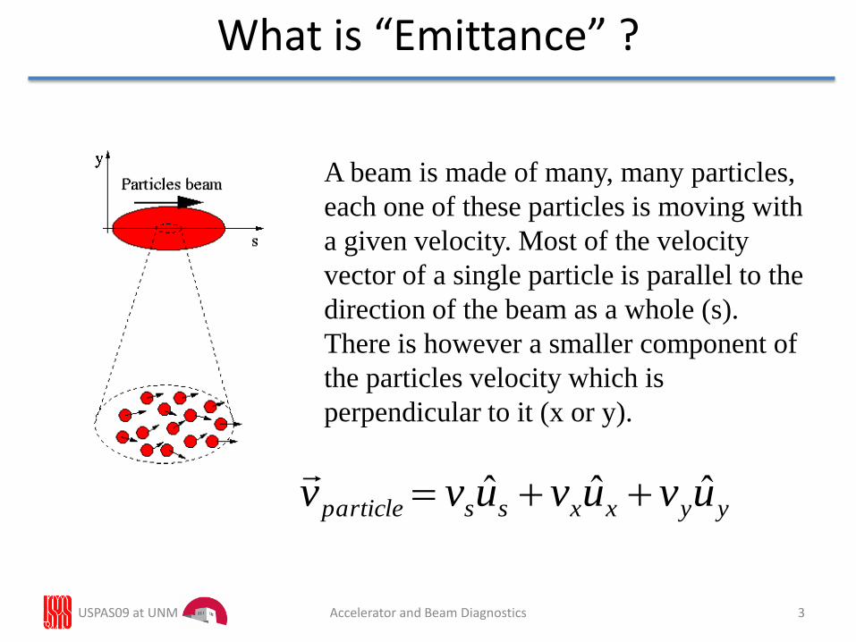
A beam is made of many, many particles,
each one of these particles is moving with
a given velocity. Most of the velocity
vector of a single particle is parallel to the
direction of the beam as a whole (s).
There is however a smaller component of
the particles velocity which is
perpendicular to it (x or y).
yyxxssparticle uvuvuvv ˆˆˆ
Transverse Phase Space
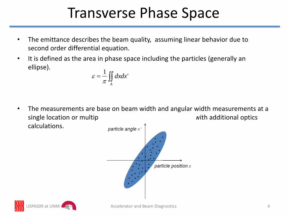
• The emittance describes the beam quality, assuming linear behavior due to second order differential equation.
• It is defined as the area in phase space including the particles (generally an ellipse).
• The measurements are base on beam width and angular width measurements at a single location or multiple measurements of beam width with additional optics calculations.
USPAS09 at UNM 4Accelerator and Beam Diagnostics
A
dxdx'1
USPAS09 at UNM 5Accelerator and Beam Diagnostics
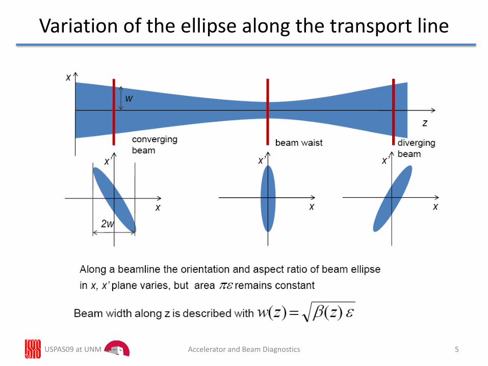
Variation of the ellipse along the transport line
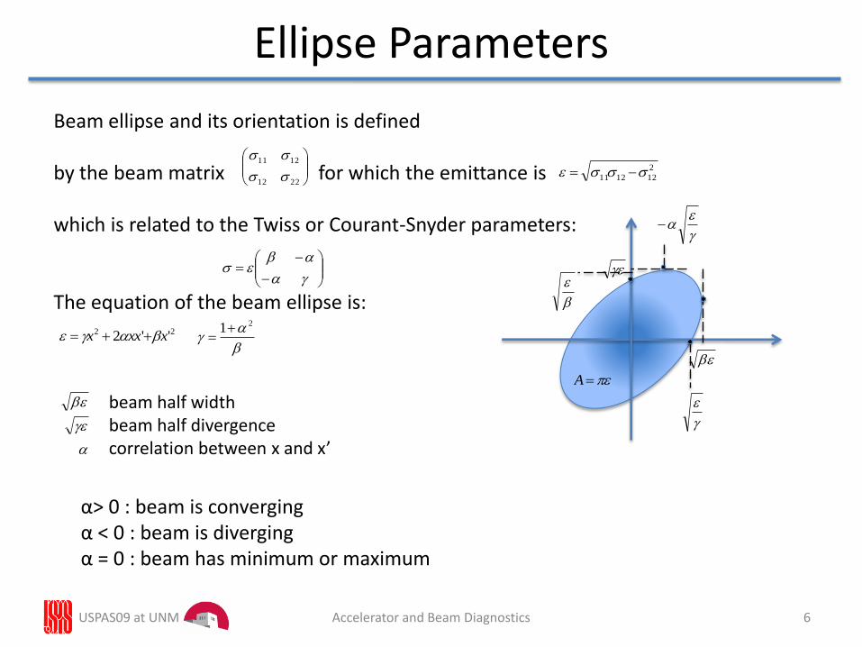
Ellipse Parameters
USPAS09 at UNM Accelerator and Beam Diagnostics 6
Beam ellipse and its orientation is defined
by the beam matrix for which the emittance is
which is related to the Twiss or Courant-Snyder parameters:
The equation of the beam ellipse is:
22 ''2 xxxx
2212
1211
A
21
beam half widthbeam half divergencecorrelation between x and x’
α> 0 : beam is convergingα < 0 : beam is divergingα = 0 : beam has minimum or maximum
2
121211
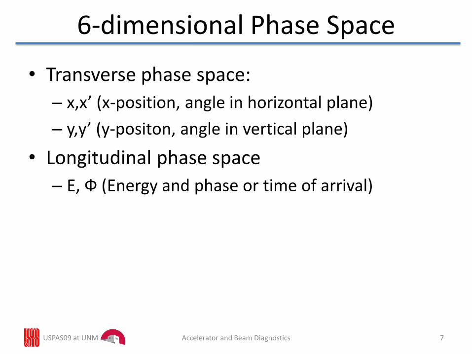
• Transverse phase space:
– x,x’ (x-position, angle in horizontal plane)
– y,y’ (y-positon, angle in vertical plane)
• Longitudinal phase space
– E, Ф (Energy and phase or time of arrival)
USPAS09 at UNM 7Accelerator and Beam Diagnostics
6-dimensional Phase Space
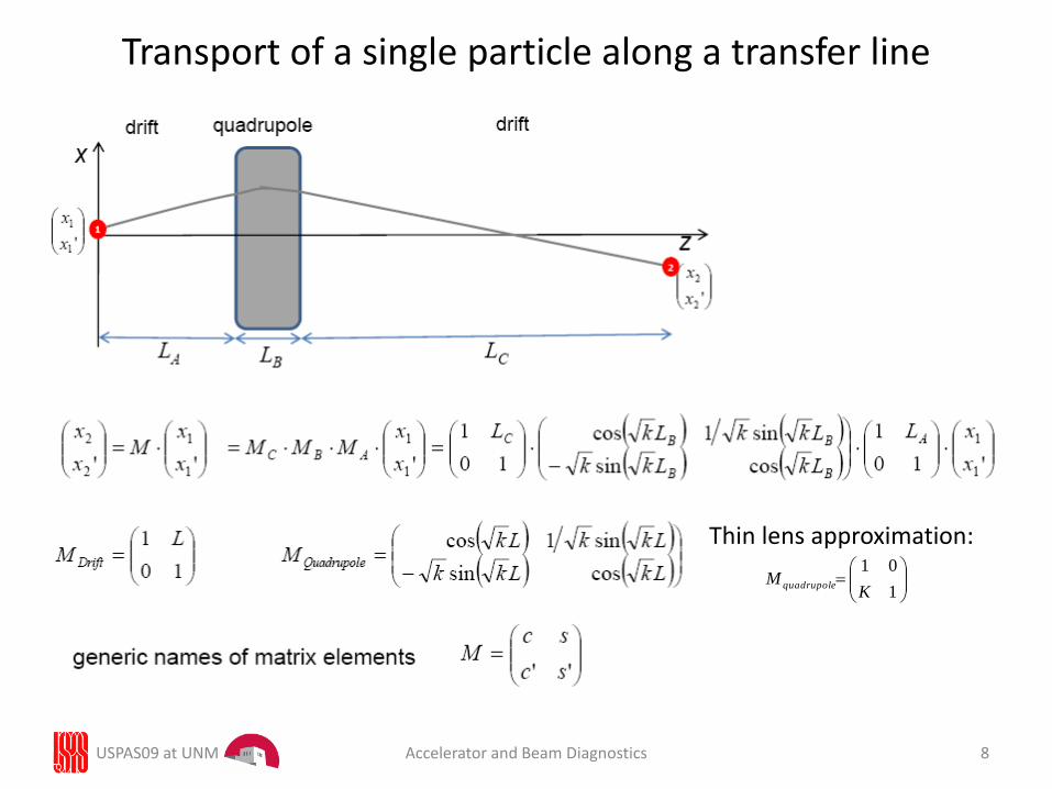
Transport of a single particle along a transfer line
USPAS09 at UNM Accelerator and Beam Diagnostics 8
Thin lens approximation:
1
01
KM quadrupole
USPAS09 at UNM 9Accelerator and Beam Diagnostics
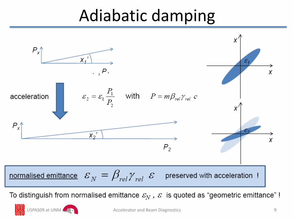
Adiabatic damping
USPAS09 at UNM 10Accelerator and Beam Diagnostics
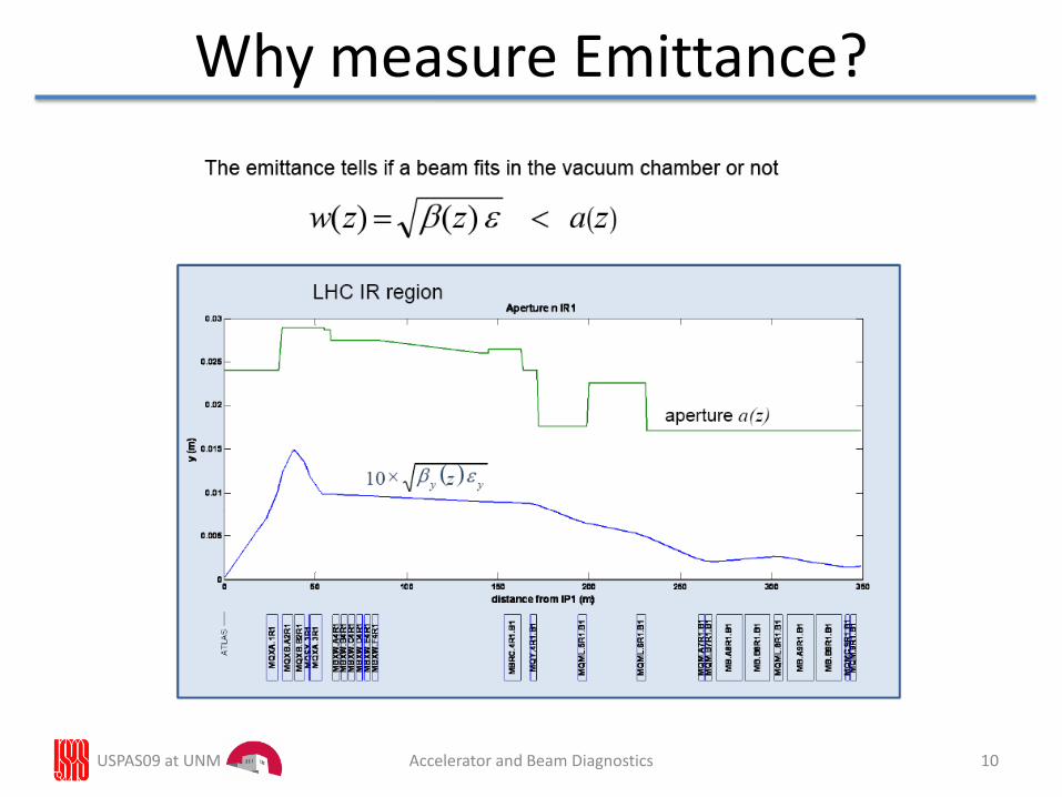
Why measure Emittance?
USPAS09 at UNM 11Accelerator and Beam Diagnostics
Why measure Emittance?
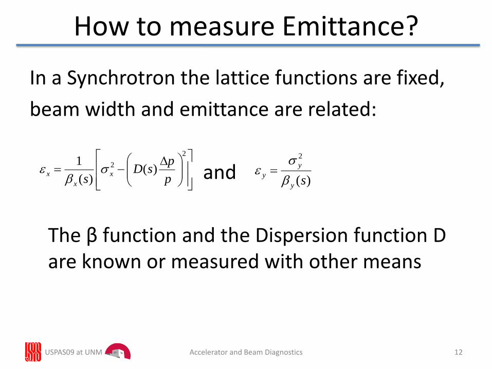
In a Synchrotron the lattice functions are fixed,
beam width and emittance are related:
and
The β function and the Dispersion function D are known or measured with other means
USPAS09 at UNM 12Accelerator and Beam Diagnostics
How to measure Emittance?
2
2 )()(
1
p
psD
sx
x
x
)(
2
sy
y
y
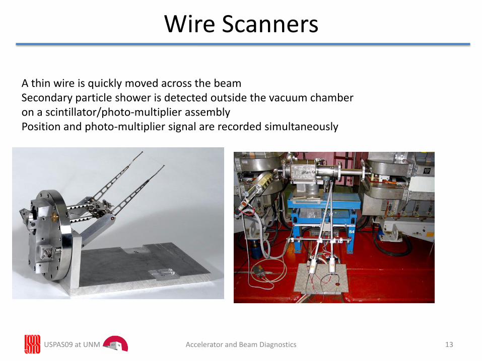
Wire Scanners
A thin wire is quickly moved across the beamSecondary particle shower is detected outside the vacuum chamberon a scintillator/photo-multiplier assembly Position and photo-multiplier signal are recorded simultaneously
USPAS09 at UNM 13Accelerator and Beam Diagnostics
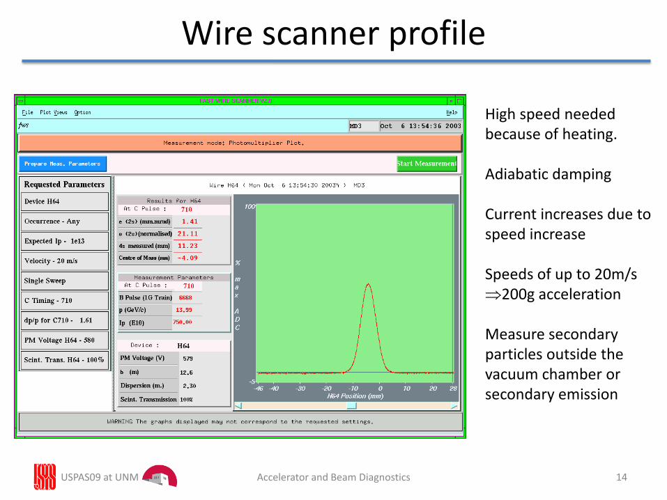
Wire scanner profile
High speed neededbecause of heating.
Adiabatic damping
Current increases due tospeed increase
Speeds of up to 20m/s200g acceleration
Measure secondary particles outside thevacuum chamber orsecondary emission
USPAS09 at UNM 14Accelerator and Beam Diagnostics
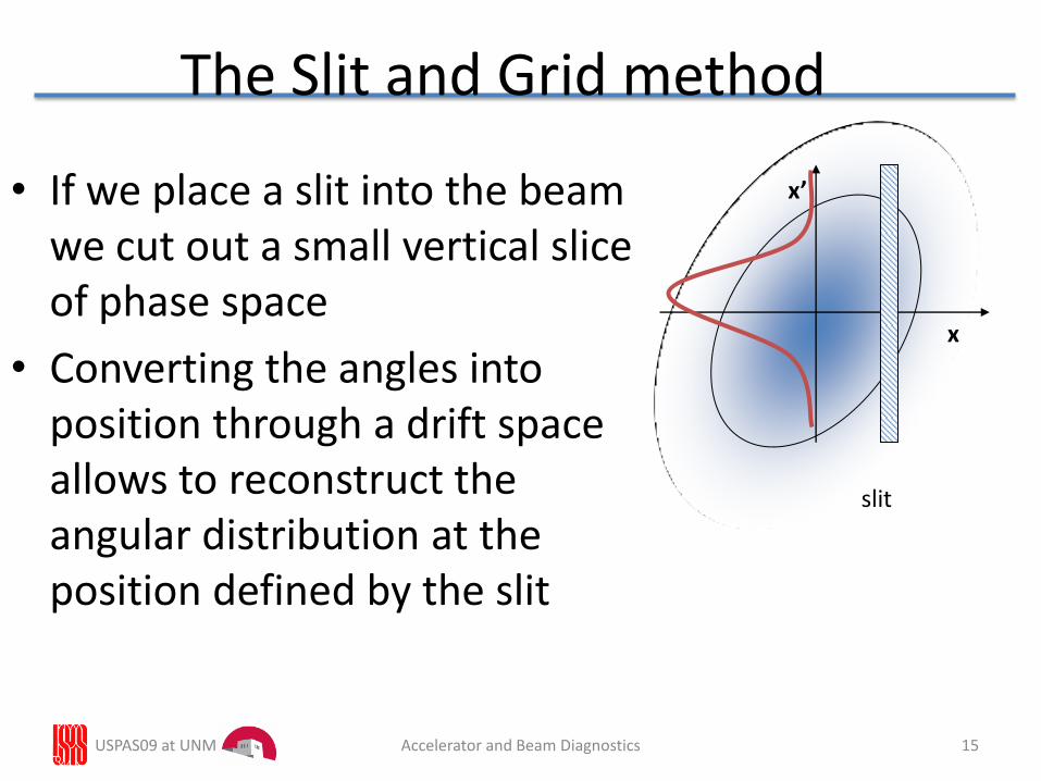
The Slit and Grid method
• If we place a slit into the beam we cut out a small vertical slice of phase space
• Converting the angles into position through a drift space allows to reconstruct the angular distribution at the position defined by the slit
x’
x
slit
15USPAS09 at UNM Accelerator and Beam Diagnostics
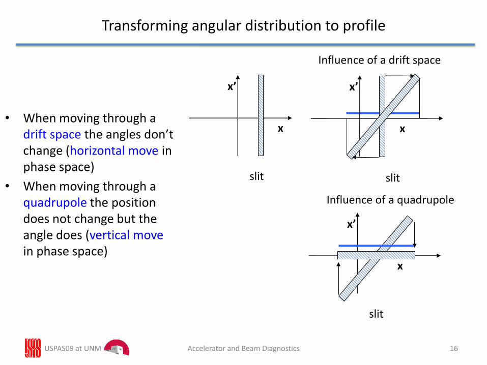
Transforming angular distribution to profile
• When moving through a drift space the angles don’t change (horizontal move in phase space)
• When moving through a quadrupole the position does not change but the angle does (vertical movein phase space)
x’
x
slit
x’
x
slit
x’
x
slit
Influence of a drift space
Influence of a quadrupole
USPAS09 at UNM 16Accelerator and Beam Diagnostics
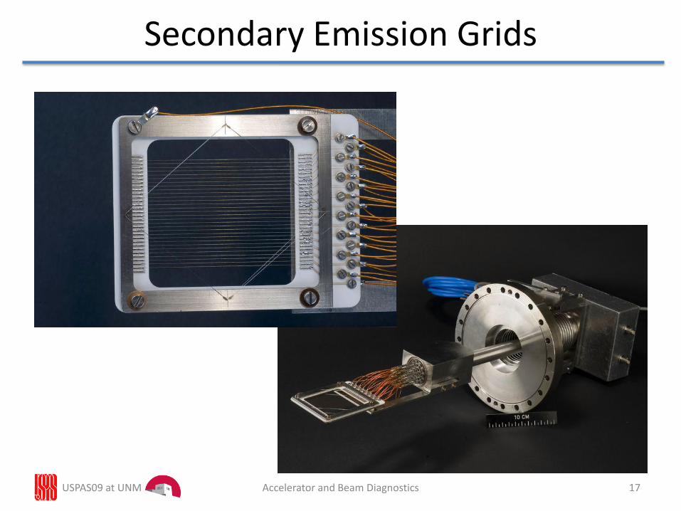
Secondary Emission Grids
USPAS09 at UNM 17Accelerator and Beam Diagnostics
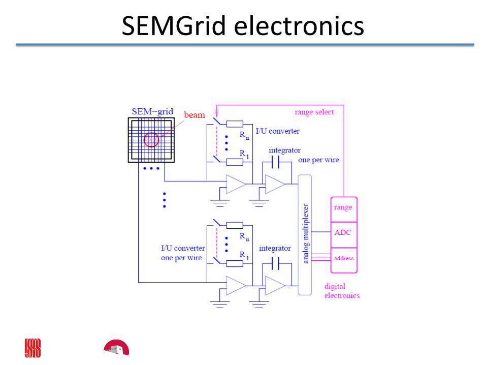
SEMGrid electronics
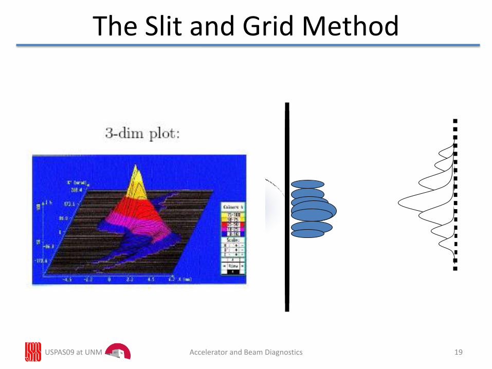
The Slit and Grid Method
Accelerator and Beam DiagnosticsUSPAS09 at UNM 19
Moving slit emittance measurement
• Position resolution given by slit size and displacement
• Angle resolution depends on resolution of profile measurement device and drift distance
• High position resolution → many slit positions → slow
• Shot to shot differences result in measurement errors
USPAS09 at UNM 20Accelerator and Beam Diagnostics

Transverse emittance line
Kicker QuadrupoleQuadrupole
SEMGridX’
X
X’
X
X’
X
X’
X
X’
X
at slit after 1. drift space after 1. quadrupole after 2. quadrupoleafter 2. drift space
Kicker
USPAS09 at UNM 21Accelerator and Beam Diagnostics
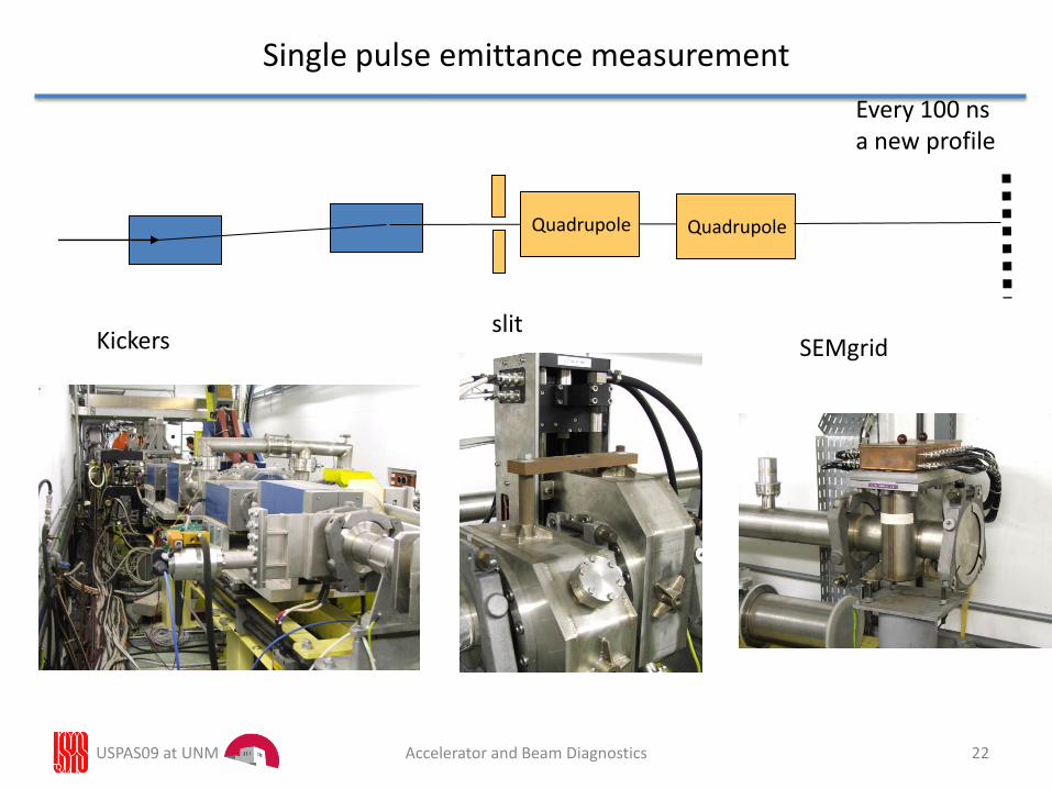
Single pulse emittance measurement
Kickersslit
SEMgrid
Every 100 nsa new profile
Quadrupole Quadrupole
22USPAS09 at UNM Accelerator and Beam Diagnostics
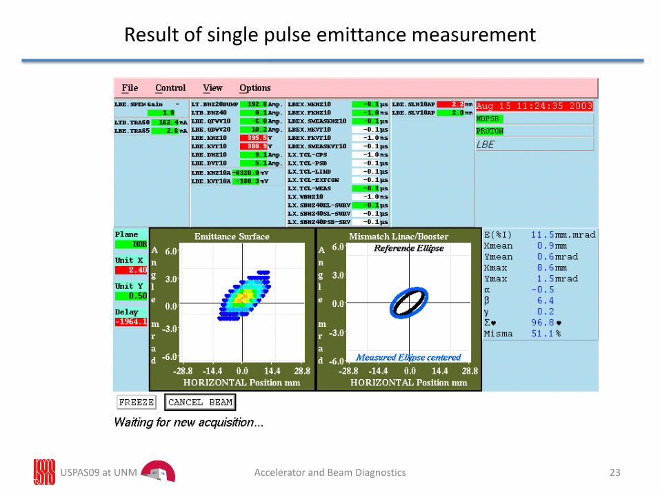
Result of single pulse emittance measurement
23USPAS09 at UNM Accelerator and Beam Diagnostics
Single Shot Emittance Measurement
Advantage: Full scan takes 20 μs
Shot by shot comparison possible
Disadvantage:Very costly
Needs dedicated measurement line
Needs a fast sampling ADC + memory for each wire
Cheaper alternative:Multi-slit measurement
24USPAS09 at UNM Accelerator and Beam Diagnostics
Accelerator and Beam Diagnostics
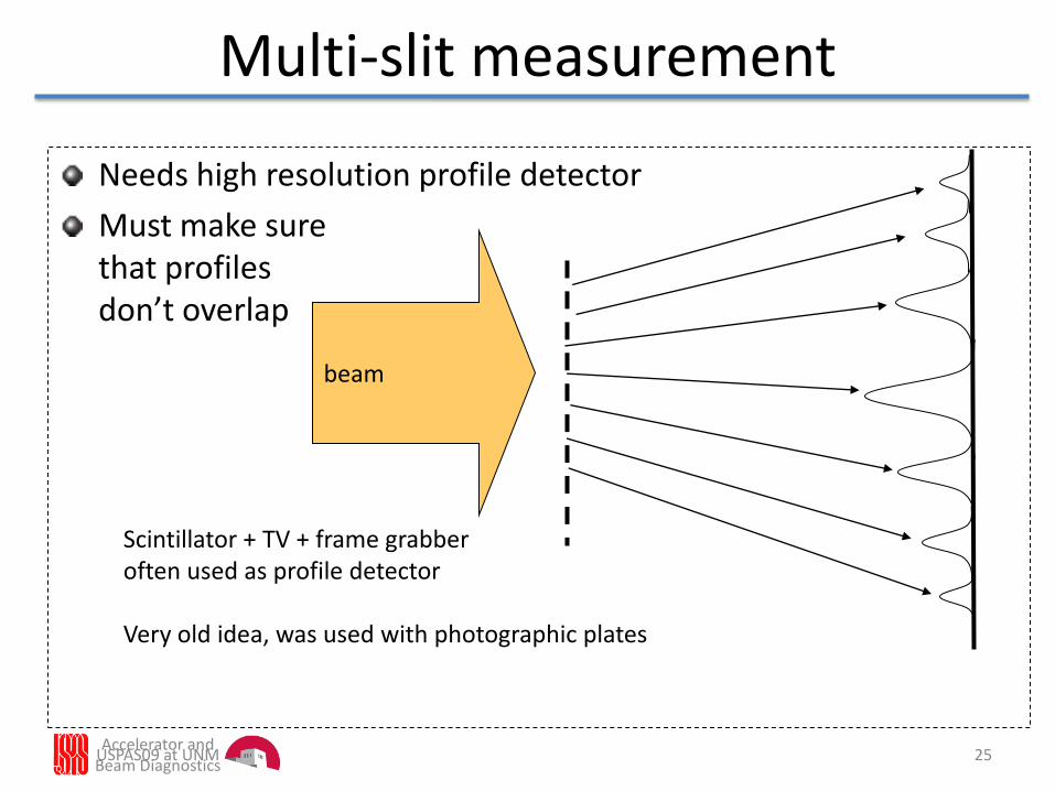
Multi-slit measurement
Needs high resolution profile detector
Must make surethat profilesdon’t overlap
beam
Scintillator + TV + frame grabberoften used as profile detector
Very old idea, was used with photographic plates
25USPAS09 at UNM
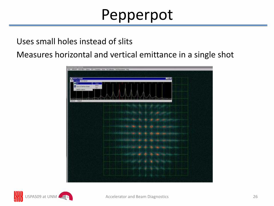
Pepperpot
Uses small holes instead of slits
Measures horizontal and vertical emittance in a single shot
26USPAS09 at UNM Accelerator and Beam Diagnostics
USPAS09 at UNM 27Accelerator and Beam Diagnostics
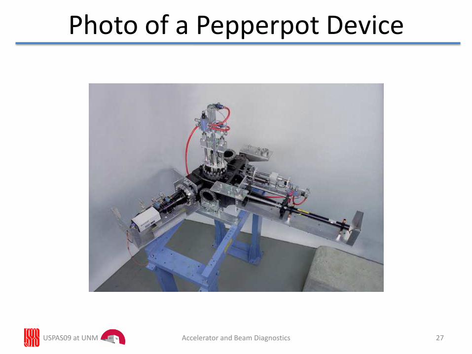
Photo of a Pepperpot Device
Accelerator and Beam Diagnostics 28
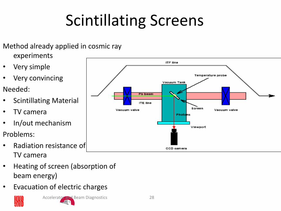
Scintillating Screens
Method already applied in cosmic ray experiments
• Very simple
• Very convincing
Needed:
• Scintillating Material
• TV camera
• In/out mechanism
Problems:
• Radiation resistance of TV camera
• Heating of screen (absorption ofbeam energy)
• Evacuation of electric charges
Accelerator and Beam Diagnostics
29
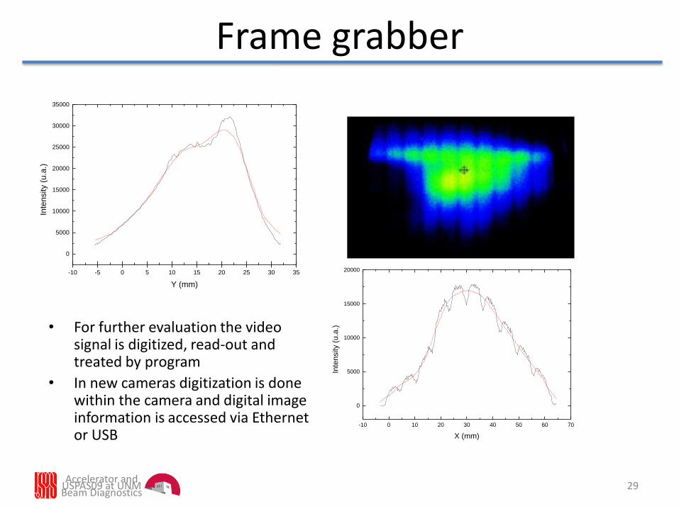
Frame grabber
• For further evaluation the video signal is digitized, read-out and treated by program
• In new cameras digitization is done within the camera and digital image information is accessed via Ethernet or USB
-10 -5 0 5 10 15 20 25 30 35
0
5000
10000
15000
20000
25000
30000
35000
Inte
nsity (
u.a
.)
Y (mm)
-10 0 10 20 30 40 50 60 70
0
5000
10000
15000
20000
Inte
nsity (
u.a
.)
X (mm)
USPAS09 at UNM
Accelerator and Beam Diagnostics
30
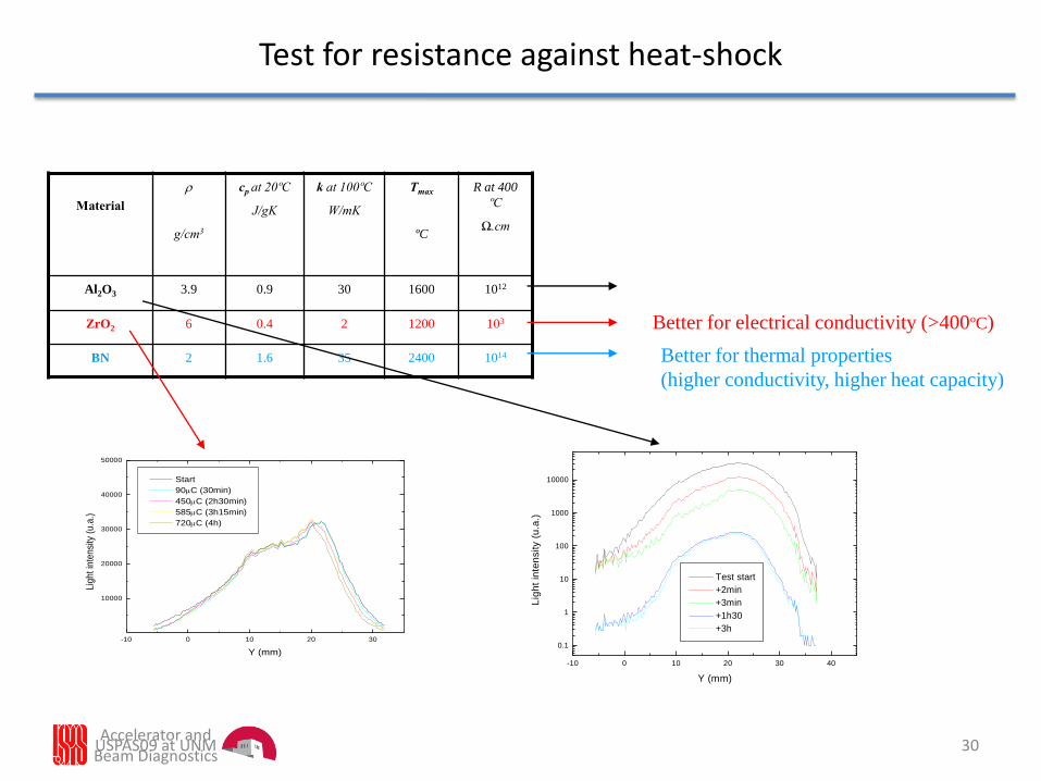
Test for resistance against heat-shock
-10 0 10 20 30 40
0.1
1
10
100
1000
10000
Test start
+2min
+3min
+1h30
+3h
Lig
ht
inte
nsity (
u.a
.)
Y (mm)
-10 0 10 20 30
10000
20000
30000
40000
50000
Start
90C (30min)
450C (2h30min)
585C (3h15min)
720C (4h)
Lig
ht
inte
nsi
ty (
u.a
.)
Y (mm)
Material
r
g/cm3
cp at 20ºC
J/gK
k at 100ºC
W/mK
Tmax
ºC
R at 400
ºC
Ω.cm
Al2O3 3.9 0.9 30 1600 1012
ZrO2 6 0.4 2 1200 103
BN 2 1.6 35 2400 1014
Better for electrical conductivity (>400ºC)
Better for thermal properties
(higher conductivity, higher heat capacity)
USPAS09 at UNM

Accelerator and Beam Diagnostics
31
Degradation of screen
Degradation clearly visibleHowever sensitivity stays essentially the same
USPAS09 at UNM
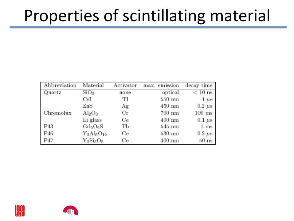
Properties of scintillating material
33
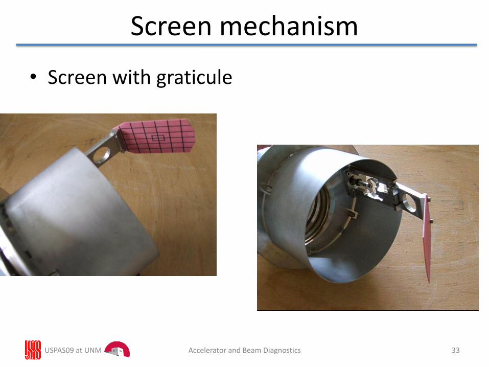
Screen mechanism
• Screen with graticule
USPAS09 at UNM Accelerator and Beam Diagnostics
• To determine ε, β, α at a reference point in a beamline one needs at least three w measurements with different transfer matrices between the reference point and the w measurements location.
• Different transfer matrices can be achieved with different profile monitor locations, different focusing magnet settings or combinations of both.
• Once β, α at one reference point is determined the values of β, α at every point in the beamline can be calculated.
• Three w measurements are in principle enough to determine ε, β, α• In practice better results are obtained with more measurements. • However, with more than three measurements the problem is over-
determined. • χ2 formalism gives the best estimate of ε, β, α for a set of n
measurements wi i=1-n with transfer matrix elements ci, si.
USPAS09 at UNM 34Accelerator and Beam Diagnostics
3 Profile Measurement and Quadrupole Scan
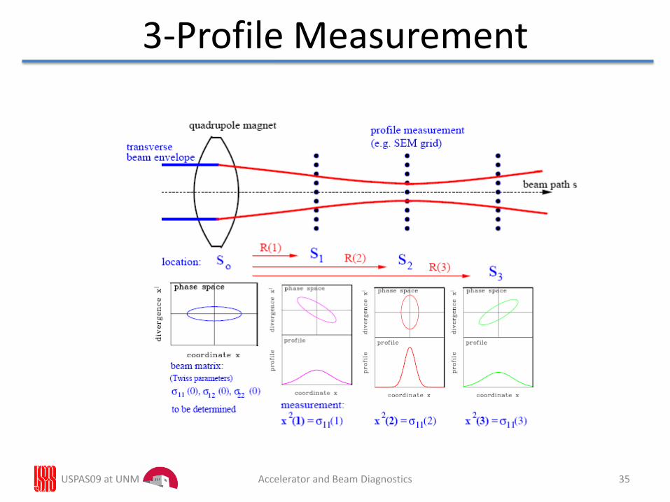
USPAS09 at UNM 35Accelerator and Beam Diagnostics
3-Profile Measurement
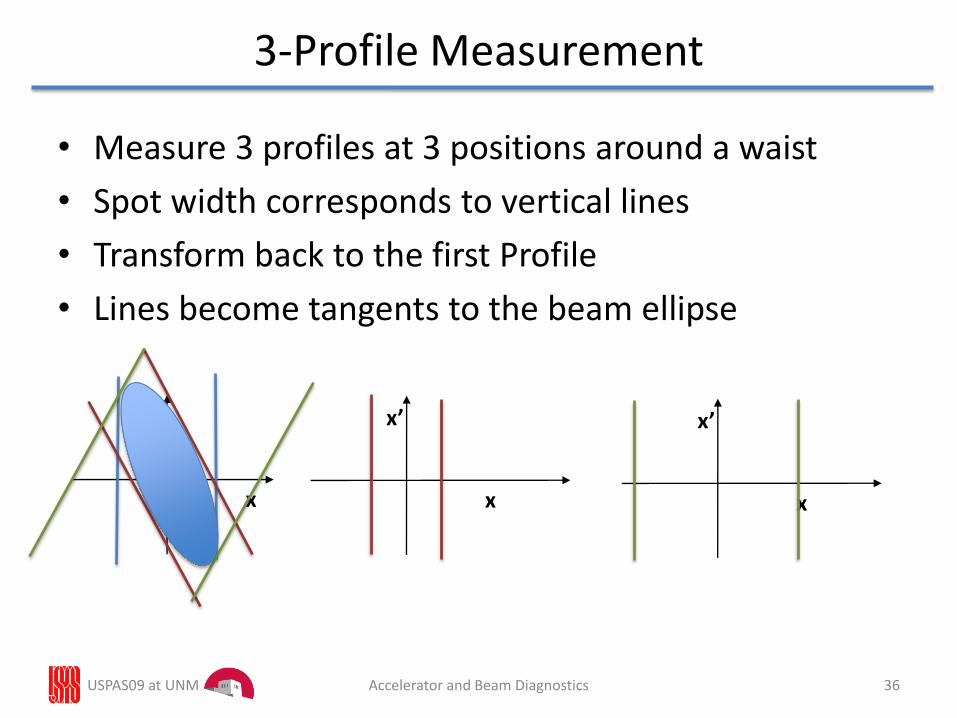
• Measure 3 profiles at 3 positions around a waist
• Spot width corresponds to vertical lines
• Transform back to the first Profile
• Lines become tangents to the beam ellipse
USPAS09 at UNM 36Accelerator and Beam Diagnostics
3-Profile Measurement
x’
x
x’
x
x’
x
USPAS09 at UNM 37Accelerator and Beam Diagnostics
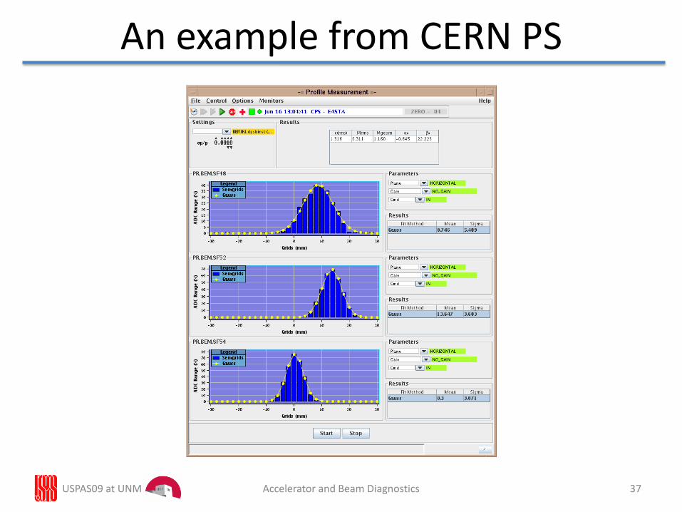
An example from CERN PS
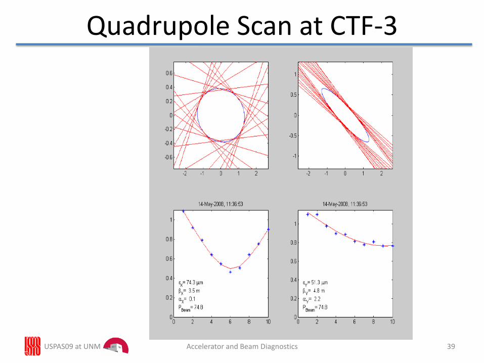
• Works the same way as the 3-Profile measurement
• The profile is taken at a fixed position (needs a single profile measurement system)
• Vary a quadrupole and measure the profile width for each quadrupole setting
USPAS09 at UNM 38Accelerator and Beam Diagnostics
Quadrupole Scan
USPAS09 at UNM 39Accelerator and Beam Diagnostics
Quadrupole Scan at CTF-3
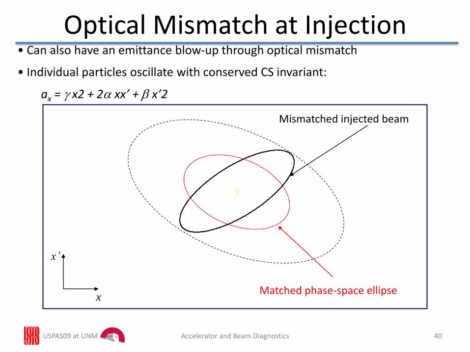
Optical Mismatch at Injection
x
x’
Matched phase-space ellipse
Mismatched injected beam
• Can also have an emittance blow-up through optical mismatch
• Individual particles oscillate with conserved CS invariant:
ax = x2 + 2 xx’ + x’2
USPAS09 at UNM 40Accelerator and Beam Diagnostics
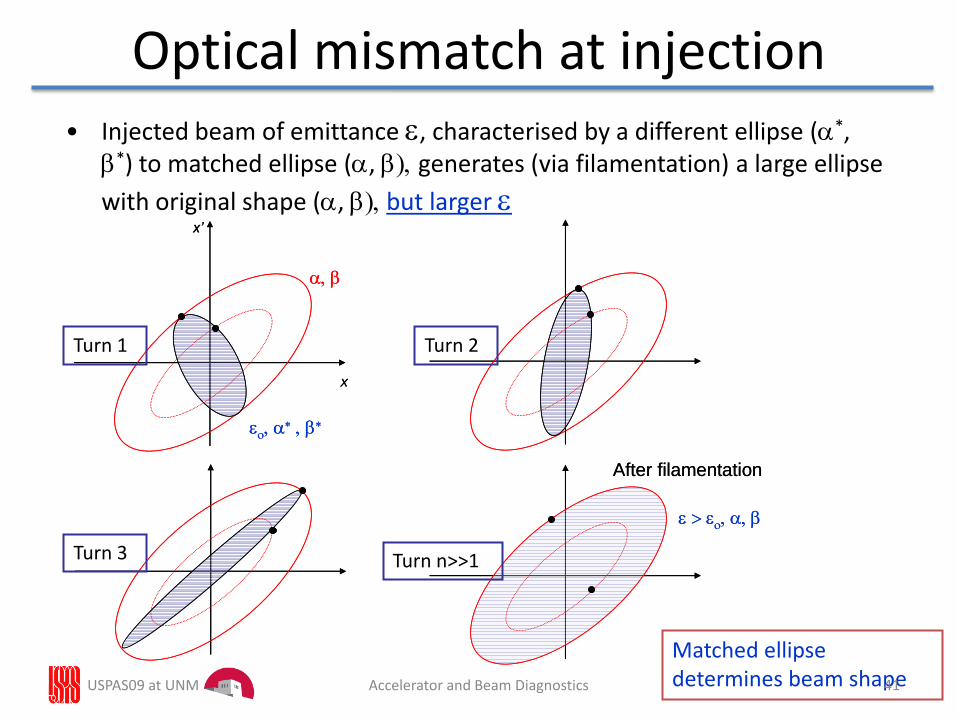
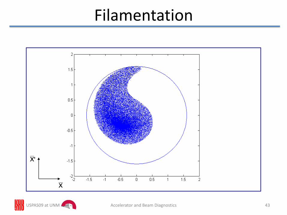
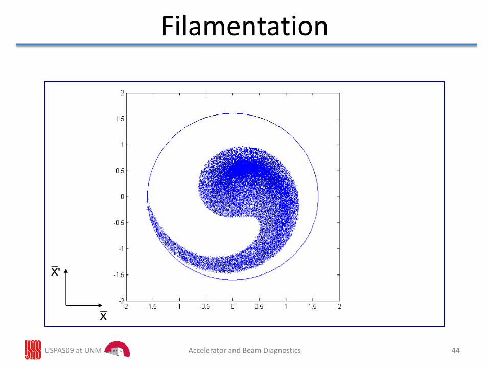
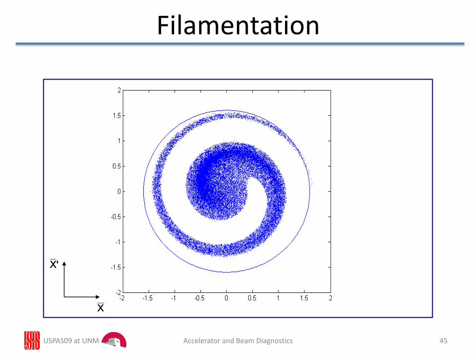
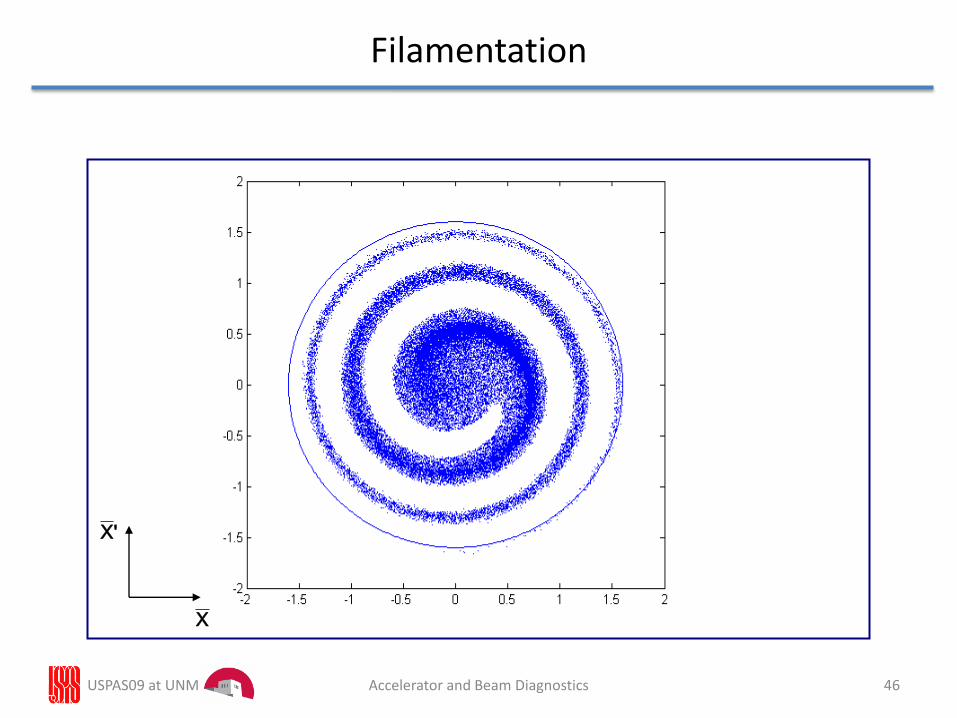
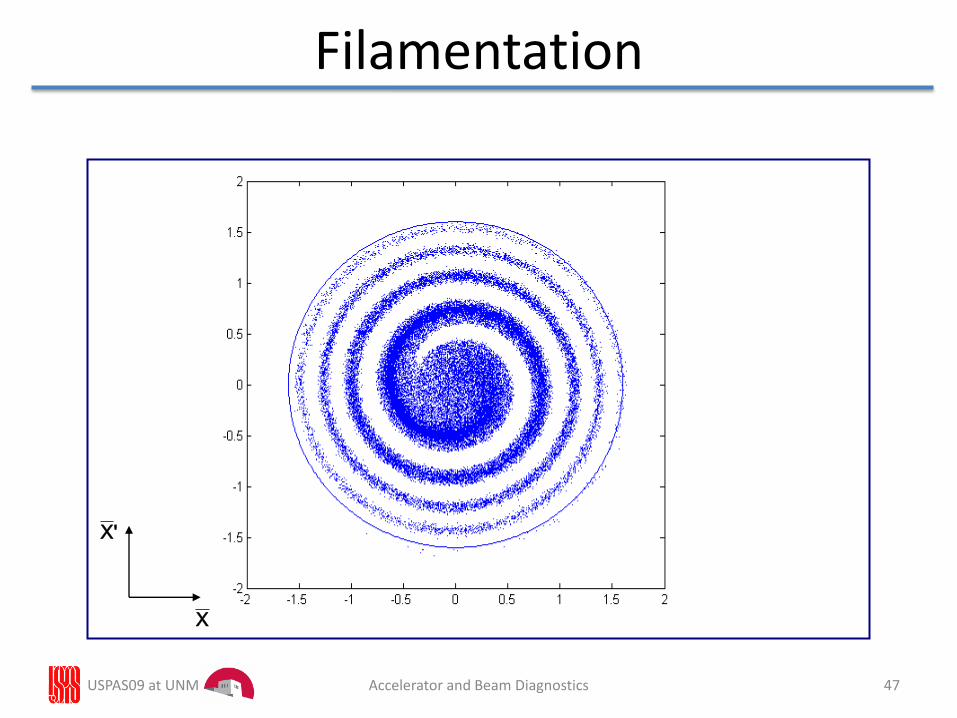
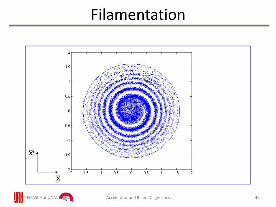
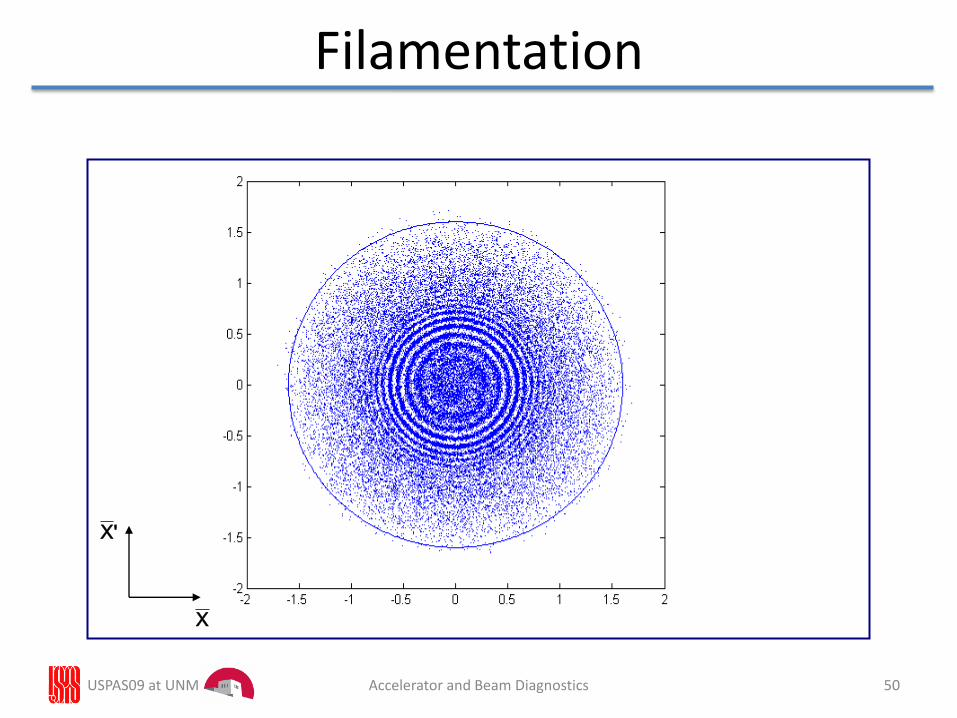
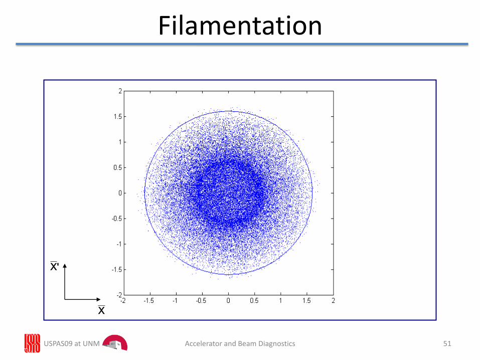
Optical mismatch at injection• Injected beam of emittance , characterised by a different ellipse (*,
*) to matched ellipse (, ) generates (via filamentation) a large ellipse
with original shape (, ) but larger
x
x’
After filamentation
x
x’
After filamentation
Matched ellipse determines beam shape
Turn 1 Turn 2
Turn 3 Turn n>>1
USPAS09 at UNM 41Accelerator and Beam Diagnostics
X
'X
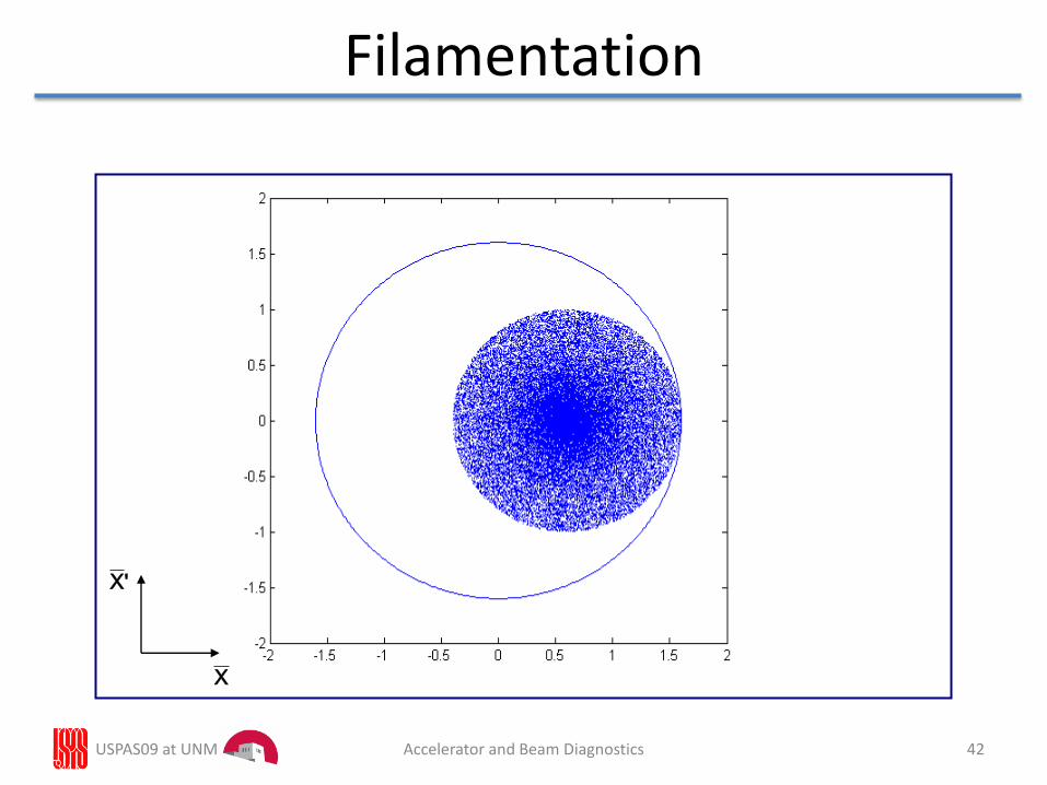
Filamentation
USPAS09 at UNM 42Accelerator and Beam Diagnostics
X
'X
Filamentation
USPAS09 at UNM 43Accelerator and Beam Diagnostics
X
'X
Filamentation
USPAS09 at UNM 44Accelerator and Beam Diagnostics
X
'X
Filamentation
USPAS09 at UNM 45Accelerator and Beam Diagnostics
Filamentation
X
'X
USPAS09 at UNM 46Accelerator and Beam Diagnostics
X
'X
Filamentation
USPAS09 at UNM 47Accelerator and Beam Diagnostics

X
'X
Filamentation
USPAS09 at UNM 48Accelerator and Beam Diagnostics
X
'X
Filamentation
USPAS09 at UNM 49Accelerator and Beam Diagnostics
X
'X
Filamentation
USPAS09 at UNM 50Accelerator and Beam Diagnostics
X
'X
Filamentation
USPAS09 at UNM 51Accelerator and Beam Diagnostics
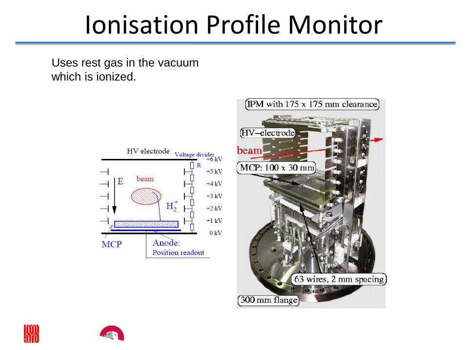
Ionisation Profile MonitorUses rest gas in the vacuum
which is ionized.
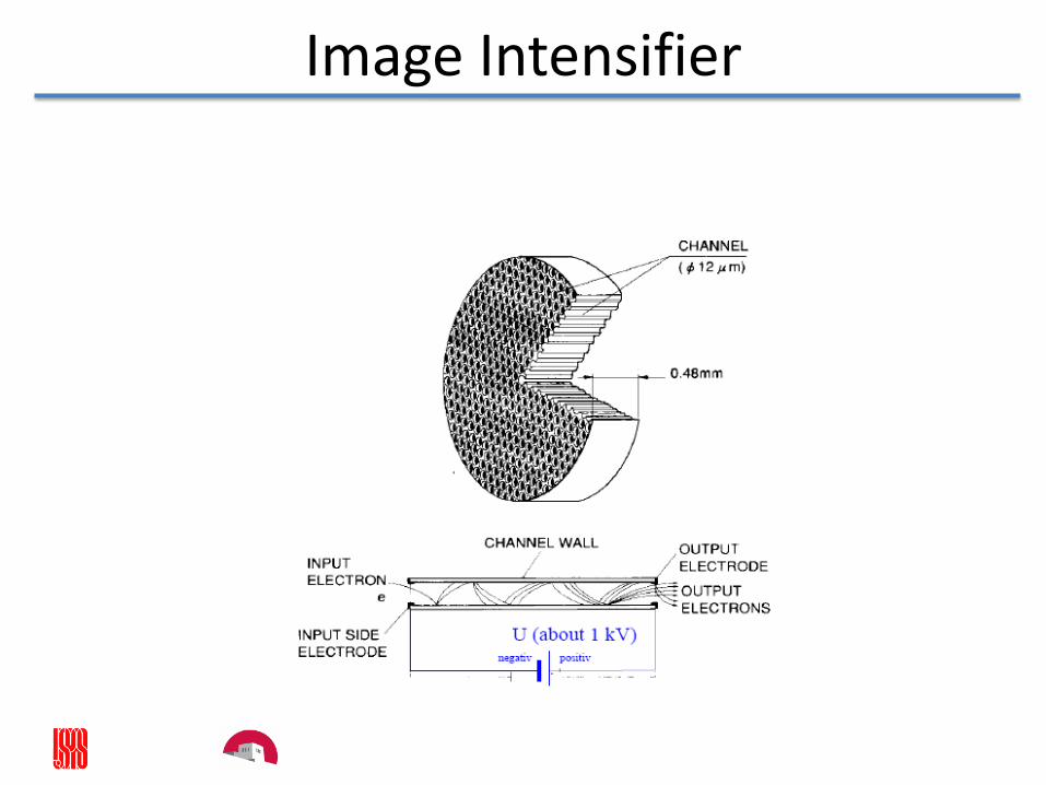
Image Intensifier
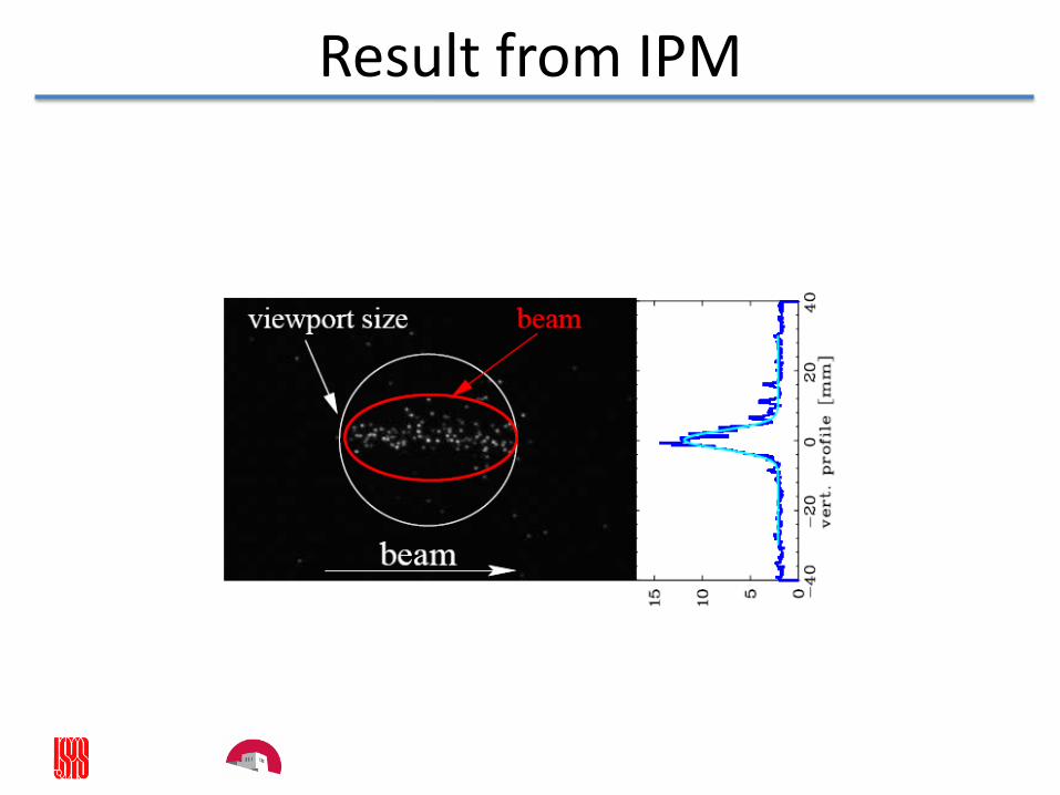
Result from IPM
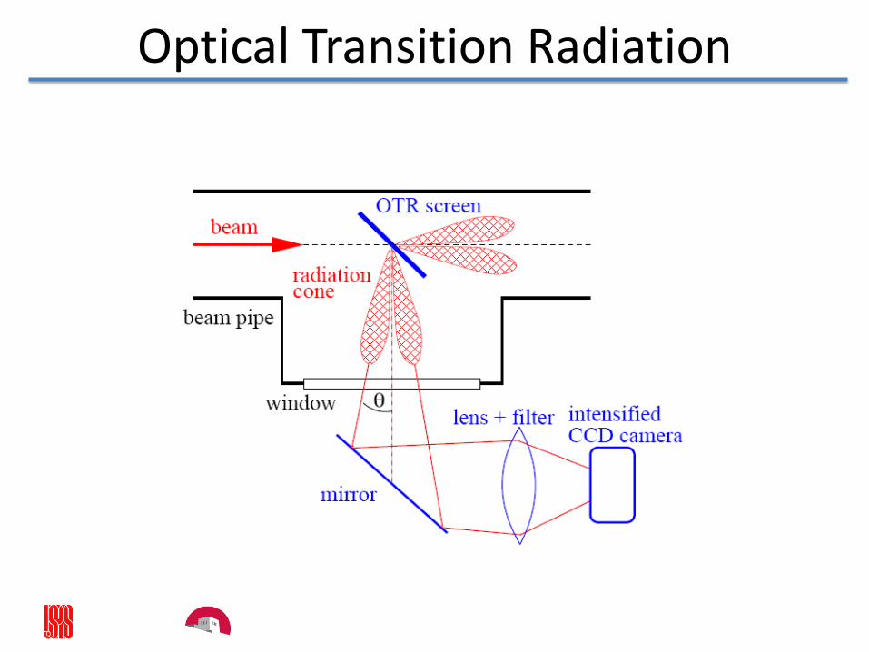
Optical Transition Radiation
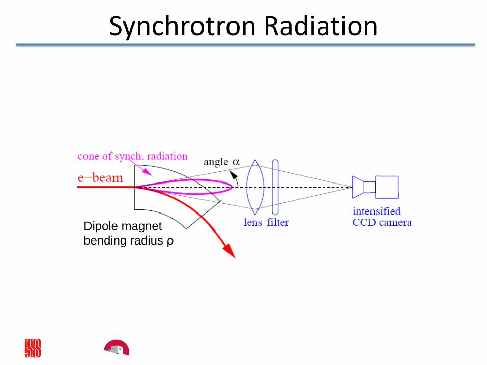
Synchrotron Radiation
Dipole magnet
bending radius ρ
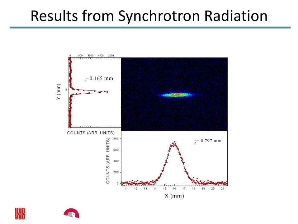
Results from Synchrotron Radiation
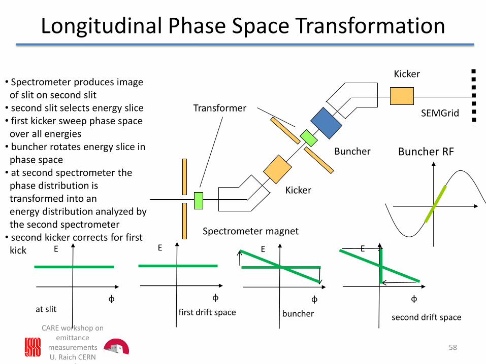
Longitudinal Phase Space Transformation
CARE workshop on emittance
measurementsU. Raich CERN
AB/BI
58
E
φ
E
φ
E
φ
E
φat slit first drift space buncher second drift space
Kicker
Buncher
Spectrometer magnet
Kicker
SEMGridTransformer
• Spectrometer produces imageof slit on second slit
• second slit selects energy slice• first kicker sweep phase space over all energies
• buncher rotates energy slice in phase space
• at second spectrometer thephase distribution istransformed into anenergy distribution analyzed bythe second spectrometer
• second kicker corrects for first kick
Buncher RF
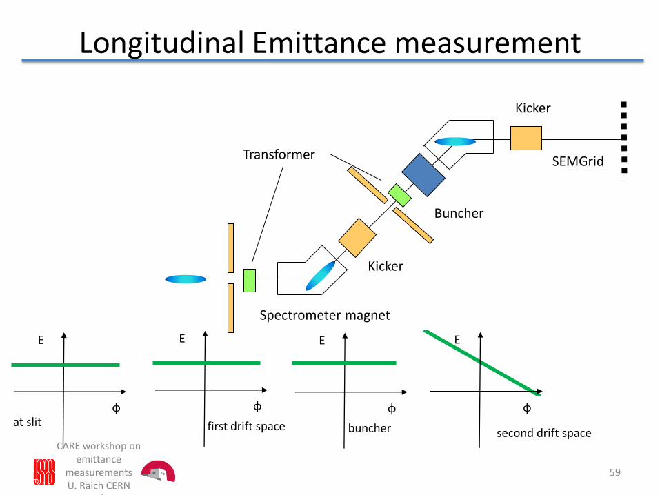
Longitudinal Emittance measurement
CARE workshop on emittance
measurementsU. Raich CERN
AB/BI
59
E
φ
E E
φ
Kicker
Buncher
Kicker
SEMGridTransformer
Spectrometer magnet
E
φat slit first drift space buncher second drift space
φ
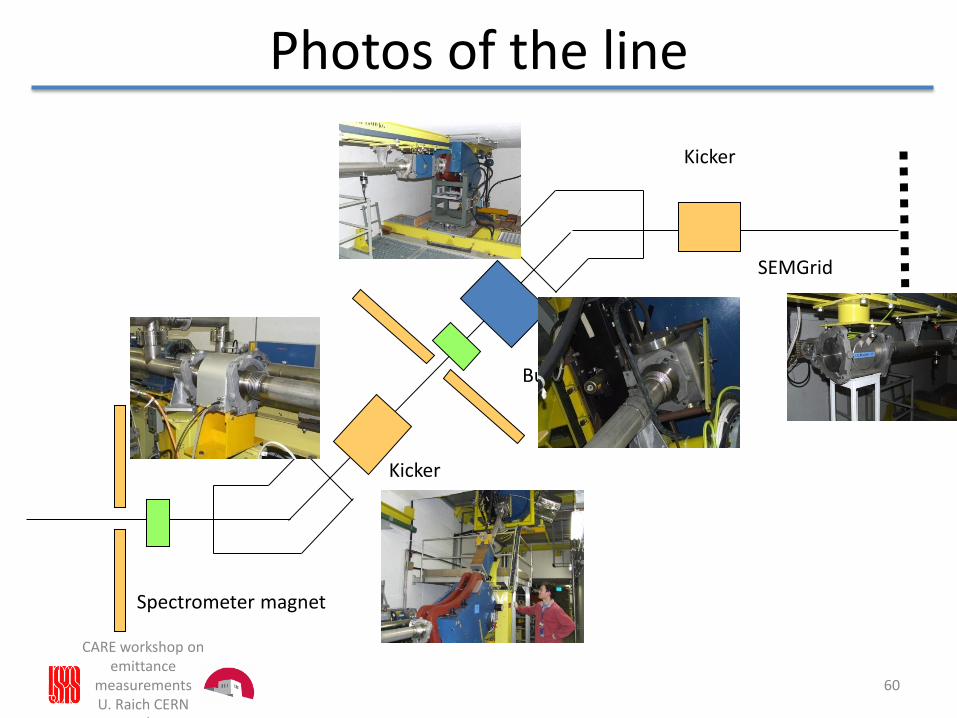
Photos of the line
CARE workshop on emittance
measurementsU. Raich CERN
AB/BI
60
Kicker
Buncher
Spectrometer magnet
Kicker
SEMGrid
U. Raich CAS Frascati 2008
Beam Diagnostics
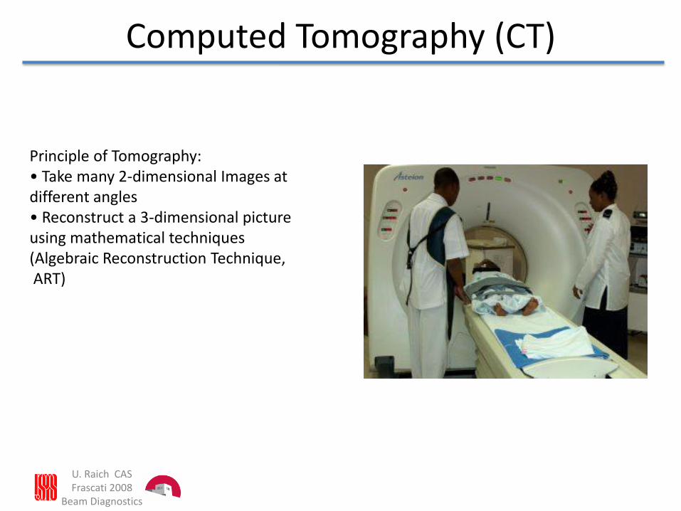
Computed Tomography (CT)
Principle of Tomography:• Take many 2-dimensional Images at different angles• Reconstruct a 3-dimensional pictureusing mathematical techniques(Algebraic Reconstruction Technique,ART)
U. Raich CAS Frascati 2008Beam Diagnostics
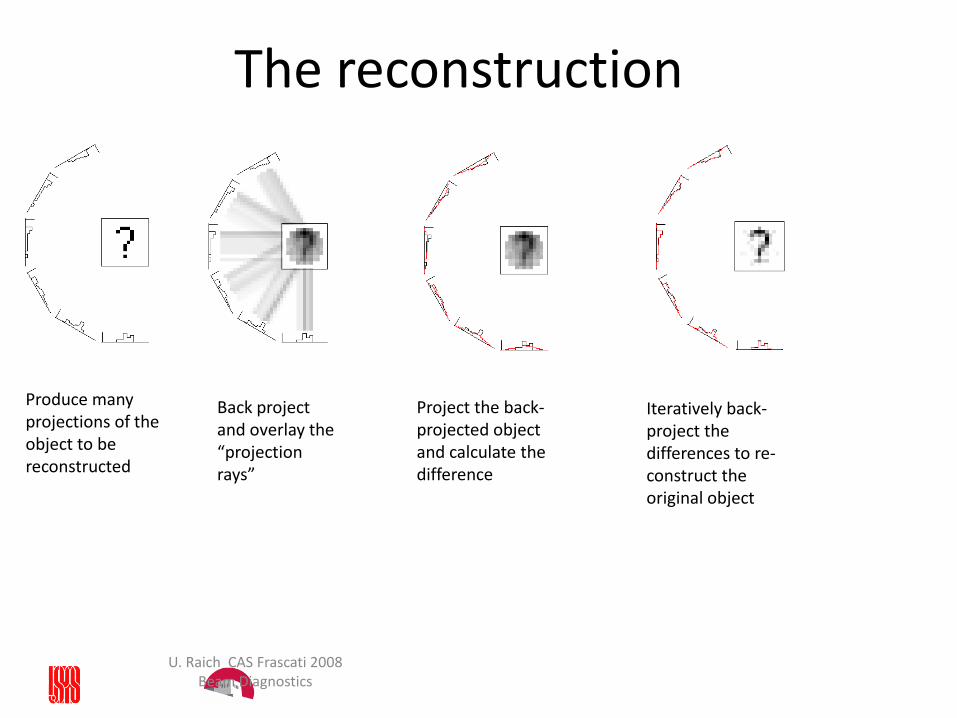
The reconstruction
Produce many projections of the object to be reconstructed
Back project and overlay the “projection rays”
Project the back-projected object and calculate the difference
Iteratively back-project the differences to re-construct the original object
U. Raich CAS Frascati 2008
Beam Diagnostics
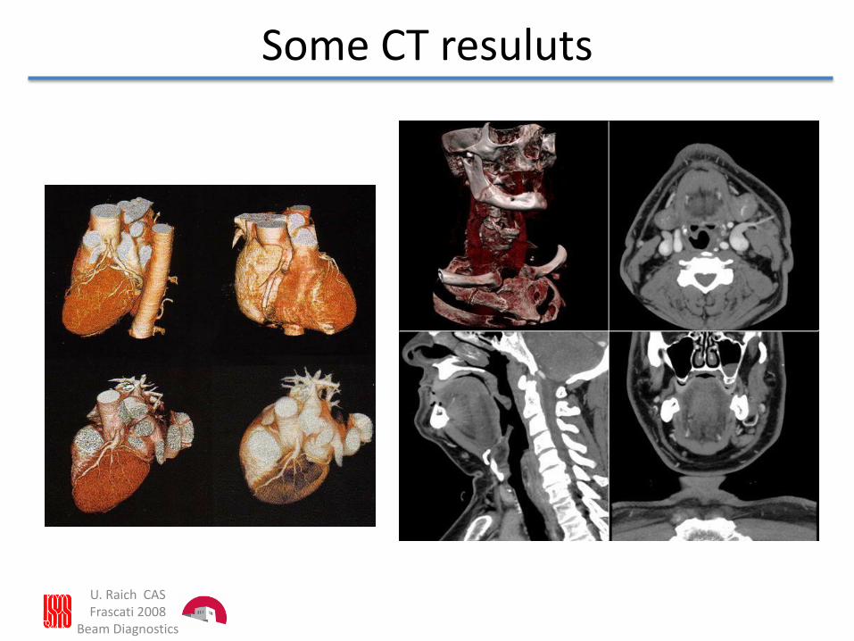
Some CT resuluts
U. Raich CAS Frascati 2008
Beam Diagnostics
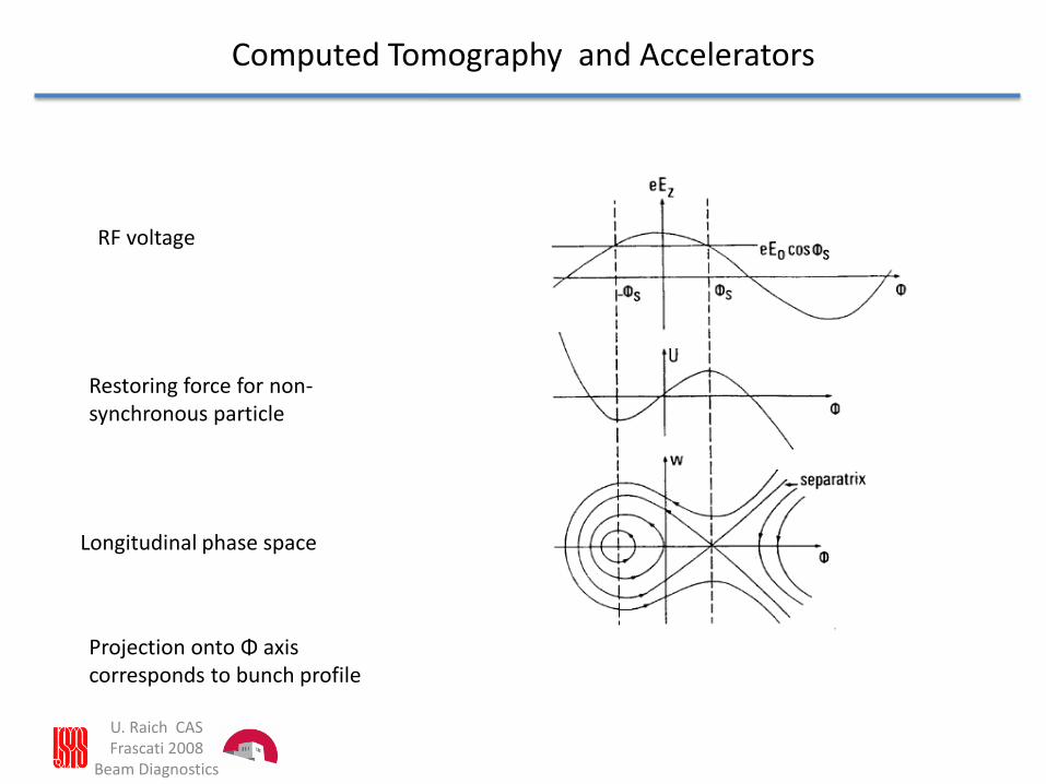
Computed Tomography and Accelerators
RF voltage
Restoring force for non-synchronous particle
Longitudinal phase space
Projection onto Φ axis corresponds to bunch profile
U. Raich CAS Frascati 2008
Beam Diagnostics
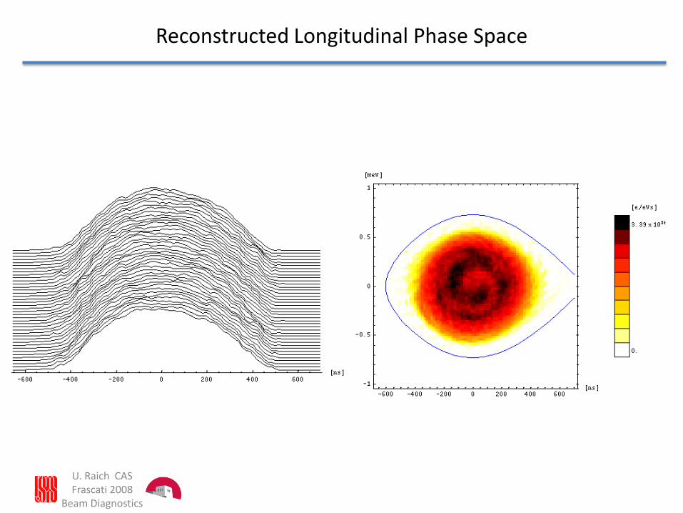
Reconstructed Longitudinal Phase Space
U. Raich CAS Frascati 2008
Beam Diagnostics
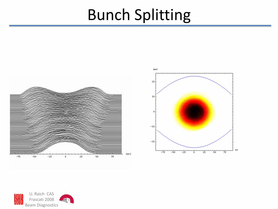
Bunch Splitting