EMERGING TECHNOLOGIES - School of Engineering …baholmen/docs/ENVE290W/National Chromium … ·...
42
-
Upload
duongtuyen -
Category
Documents
-
view
214 -
download
0
Transcript of EMERGING TECHNOLOGIES - School of Engineering …baholmen/docs/ENVE290W/National Chromium … ·...


EMERGING TECHNOLOGIES FOR THE REMEDIATION OF METALS IN SOILS
ELECTROKINETICS
-FINAL-
December 1997
Prepared byInterstate Technology and Regulatory Cooperation
Work Group Metals in Soils Work Team
Emerging Technologies Project
ABOUT ITRC Established in 1995, the Interstate Technology & Regulatory Council (ITRC) is a state-led, national coalition of personnel from the environmental regulatory agencies of some 40 states and the District of Columbia; three federal agencies; tribes; and public and industry stakeholders. The organization is devoted to reducing barriers to, and speeding interstate deployment of, better, more cost-effective, innovative environmental techniques. ITRC operates as a committee of the Environmental Research Institute of the States (ERIS), a Section 501(c)(3) public charity that supports the Environmental Council of the States (ECOS) through its educational and research activities aimed at improving the environment in the United States and providing a forum for state environmental policy makers. More information about ITRC and its available products and services can be found on the Internet at www.itrcweb.org. DISCLAIMER This document is designed to help regulators and others develop a consistent approach to their evaluation, regulatory approval, and deployment of specific technologies at specific sites. Although the information in this document is believed to be reliable and accurate, this document and all material set forth herein are provided without warranties of any kind, either express or implied, including but not limited to warranties of the accuracy or completeness of information contained in the document. The technical implications of any information or guidance contained in this document may vary widely based on the specific facts involved and should not be used as a substitute for consultation with professional and competent advisors. Although this document attempts to address what the authors believe to be all relevant points, it is not intended to be an exhaustive treatise on the subject. Interested readers should do their own research, and a list of references may be provided as a starting point. This document does not necessarily address all applicable heath and safety risks and precautions with respect to particular materials, conditions, or procedures in specific applications of any technology. Consequently, ITRC recommends also consulting applicable standards, laws, regulations, suppliers of materials, and material safety data sheets for information concerning safety and health risks and precautions and compliance with then-applicable laws and regulations. The use of this document and the materials set forth herein is at the user’s own risk. ECOS, ERIS, and ITRC shall not be liable for any direct, indirect, incidental, special, consequential, or punitive damages arising out of the use of any information, apparatus, method, or process discussed in this document. This document may be revised or withdrawn at any time without prior notice. ECOS, ERIS, and ITRC do not endorse the use of, nor do they attempt to determine the merits of, any specific technology or technology provider through publication of this guidance document or any other ITRC document. The type of work described in this document should be performed by trained professionals, and federal, state, and municipal laws should be consulted. ECOS, ERIS, and ITRC shall not be liable in the event of any conflict between this guidance document and such laws, regulations, and/or ordinances. Mention of trade names or commercial products does not constitute endorsement or recommendation of use by ECOS, ERIS, or ITRC.
ACKNOWLEDGMENTS
The members of the Interstate Technology Regulatory Cooperation (ITRC) Work Group, Metals inSoils Work Team wish to acknowledge the individuals, organizations and agencies that contributedto this Technology Overview document. We also wish to extend our thanks to those ITRC staterepresentatives who took the time to review and comment on our drafts.
The Metals in Soils Work Team effort, as part of the broader ITRC effort, is funded primarily by theUnited States Department of Energy. Additional funding has been provided by the United StatesDepartment of Defense and the United States Environmental Protection Agency. Administrativesupport for grants is provided by the Western Governors Association and the Southern States EnergyBoard.
The ITRC Metals in Soils Team also wishes to recognize the individuals who were directly involvedin this project, both in the initial stages of document development and the final stages of review andcompletion. In addition, we wish to thank the organizations who made the expertise of theseindividuals available to the ITRC on this project. The following pages list members of the ITRCMetals in Soils Team, as well as “Targeted Reviewers” who contributed significant time and energyto this project.

ii
ITRC Metals in Soils Team
Brian Sogorka, 1997 Team LeaderNJ Dept. of Environmental Protection401 East State StreetCN413, 6th FloorTrenton, NJ 08625P 609-633-1344F [email protected]
Helge Gabert Department of Environmental Quality288 North 1460 WestSalt Lake City, UT 84114-4880P 801-538-6170F [email protected]
Dib Goswami, Ph.D.Washington State Dept. of Ecology1315 W. 4th AvenueKennewick, WA 99336P 509-736-3015F [email protected]
Robert MuellerNew Jersey DEP, OIT401 East State Street CN-409Trenton, NJ 08625P 609-984-3910F [email protected]
Bill BertiDuPont Central Research & DevelopmentRoute 896Glasgow, DE 19702P 302-451-9224F [email protected]
Dirk GombertLockheed/DOE Mixed WasteIdaho Falls, ID 83415-3875P 208-526-4624F [email protected]
R. H. JensenDuPont Central Research & DevelopmentExperimental StationBuilding 304Wilmington, DE 19880-0304P 302-695-4685F [email protected]
Randy ParkerUSEPA26 W Martin Luther King DrCincinnati, OH45268P 513-569-7271F [email protected]
Dan SogorkaColeman Research Corporation12850 Middlebrook Road, Suite 306Germantown, MD 20874P 301-515-6910F [email protected]
Allen ToolUS Army Corps of EngineersKansas City District601 East 12th StreetKansas City, MO 64106-2896P 816-983-3590F [email protected]
iii
ITRC Metals in Soils “Targeted Reviewers”
Yalcin AcarEK, Inc.Louisiana State UniversitySouth Stadium DriveBaton Rouge, LA 70803-6100P 504-388-3992
Gary BaughmanCO Dept. Public Health & Environment4300 Cherry Creek Drive SouthDenver, CO 80222-1530P 303-692-3338F [email protected]
Mark BrickaUSAE-WES-WSEE-R3909 Halls Ferry RoadVicksburg, MS 39180P 601-634-3700F [email protected]
Jim CummingsUSEPA Technology Innovation Office1235 Jefferson Davis Hwy.13th Floor - 5102-WArlington, VA 22202P 703-603-7197F 703-603-9135
John DrexlerDept of Geological SciencesUniv Colorado, BoulderCampus Box 250Boulder, CO 80209P 303-492-5251F [email protected]
Burt EnsleyPhytotech, Inc.One Deer Park DriveMonmouth Junction, NJ 08852P 908-438-0900 Annette GatchettUSEPA / NRMRL26 W. Martin Luther King DriveCincinnati, Ohio 45268P 513-569-7697F [email protected]
Jim HarringtonNY Dept of Environmental Conservation50 Wolf Road, Room 265Albany, NY 12233-7010P 518-457-0337F [email protected]
Mike HightowerSandia National LabsP.O. Box 5800Albuquerque, NM 87185P [email protected]
Peter JaffeyCivil Engineering Dept.Princeton University319 Engineering QuadPrinceton, NJ 08544P 609-258-4653F 609-258-2799

iv
Mike KrstichEnvironmental Mgt Solutions3520 Stettinius AveSuite 1Cincinnati, Ohio 45208P 513-697-6682
Bal LeeCAL-EPADept of Toxic Substances Control400 P Street, 4th FloorSacramento, CA 95812-0806P 916-322-8036F 916-323-3700
Tom LeggiereContraCon4519 131st Place, SWMukilteo, WA 98275P 206-787-9600F [email protected]
Eric R. LindgrenSandia National LabsAlbuquerque, NM 87185-0719P 505-844-3820F [email protected]
Bill LoweRoy F. Weston1 Weston WayWestchester, PA 19380P 610-701-3762F 610-701-7597
Michael J. MannAlternative Remedial Technologies, Inc.Tampa, Florida 33618P 813-264-3506F [email protected]
Dave MosbyMissouri Dept of Natural ResourcesP.O. Box 176Jefferson City, MO 65102P 573-751-1288
Marshall W. Nay, Jr.BDM International, Inc.1801 Randolph Road, SEAlbuquerque, NM 87106P 505-848-5281F [email protected]
Margaret B. MartinCENAB-EN-HTPO Box 1715Baltimore, MD 21203P 410-962-3500F [email protected]
Barbara NelsonNFESC1100 23rd AvenuePort Hueneme, CA 93043P 805-982-1668F [email protected]
Rick O’DonnellArmy Environmental CenterBuilding E-4430Aberdeen Proving Ground, MD 21020-5401P 410-612-6850F 410-612-6836

v
Dale PflugTechcon ProgramArgonne National Laboratory9700 S. Cass Ave, EAD-900Argonne, IL 60439P 630-252-6682F [email protected]
Gary PiezynskiDept of Agronomy, Kansas St UnivManhattan, KS 66506P 913-532-7209F [email protected]
Laurie PeterfreundNCEIT121 South Meramec 9th FloorSt. Louis, Missouri 63105P [email protected]
Ron ProbsteinM.I.T.Dept. Of Mechanical EngineeringCambridge, MA 02139P 617-254-2240
Chris RendaEnvironmental Services Network2112 South Columbine StreetDenver, CO 80210P 303-777-1189F [email protected]
Mike RubyPTI Environmental Services4940 Pearl East CircleBoulder, CO 80301P 303-444-7270F 303-444-7528
Jim RyanUSEPA, National Risk Mgt Research Lab26 West Martin Luther King DriveCincinnati, OH 45268P 513-569-7653F [email protected]
Chander ShekherDuPont EnvironmentalBarkley Mill Plaza, Bldg. #27Wilmington, Delaware 19880-0027P 302-992-6992F [email protected]
Cynthia TeeterUSCE-WES-WESEE-R3909 Halls Ferry RoadVicksburg, MS 39180P 601-634-4260F [email protected]
Rick Traver150 Airport RoadGallatin, TN 37066P 615-230-6579 Paul W. WangSpecial Technologies Laboratory5520 Ekwill Street, Suite BSanta Barbara, CA 93111P 805-681-2265
vii
EXECUTIVE SUMMARY
Electrokinetic remediation is a developing technology for in-situ removal of heavy metals andradionuclides from contaminated soil. This document provides general information on thetechnology, including background, applicability and potential advantages and limitations ofelectrokinetic remediation techniques. In addition, this technology overview discusses currentapproaches to electrokinetic remediation and identifies future research and development needs. Datafrom several case studies are presented, as are regulatory and stakeholder concerns related toelectrokinetic technology implementation at contaminated sites. While the technology can be appliedto treat a variety of contaminants, this document focuses mainly on the remediation of metals in soils.
Membership on this work team was open to all ITRC members. Participants with expertise orinterest in metals treatment technologies in their states elected to join the team and contributedconsistently to the development of this work product. Members of the RTDF (RemediationTechnologies Development Forum) IINERT technology team (In-Place Inactivation and NaturalEcological Restoration Technologies) also participated on this team and helped to provide an industryperspective. A representative from the U.S. Army Corps of Engineers and the Department of Energyactively participated on the team. Support was also provided by the United States EnvironmentalProtection Agency and the Department of Defense. Input regarding public and community concernsfor these technologies was provided by ITRC public stakeholder representatives.
ITRC - Emerging Technologies for the Remediation of December 1997Metals in Soils--Electrokinetic Remediation - FINAL -
viii
TABLE OF CONTENTS
ACKNOWLEDGMENTS . . . . . . . . . . . . . . . . . . . . . . . . . . . . . . . . . . . . . . . . . . . . . . . . . . . . . .i
EXECUTIVE SUMMARY . . . . . . . . . . . . . . . . . . . . . . . . . . . . . . . . . . . . . . . . . . . . . . . . . . . .vii
1.0 INTRODUCTION . . . . . . . . . . . . . . . . . . . . . . . . . . . . . . . . . . . . . . . . . . . . . . . . . . . . . 11.1 Background . . . . . . . . . . . . . . . . . . . . . . . . . . . . . . . . . . . . . . . . . . . . . . . . . . . . 11.2 Applicability . . . . . . . . . . . . . . . . . . . . . . . . . . . . . . . . . . . . . . . . . . . . . . . . . . . . 21.3 Potential Advantages and Limitations of Electrokinetics . . . . . . . . . . . . . . . . . . . 2
2.0 APPROACHES TO ELECTROKINETICS TECHNOLOGY . . . . . . . . . . . . . . . . . . . . 42.1 General . . . . . . . . . . . . . . . . . . . . . . . . . . . . . . . . . . . . . . . . . . . . . . . . . . . . . . . . 42.2 Site Screening . . . . . . . . . . . . . . . . . . . . . . . . . . . . . . . . . . . . . . . . . . . . . . . . . . 42.3 Current Applications . . . . . . . . . . . . . . . . . . . . . . . . . . . . . . . . . . . . . . . . . . . . . . 5
3.0 RESEARCH AND DEVELOPMENT—FUTURE NEEDS . . . . . . . . . . . . . . . . . . . . . . 5
4.0 CASE STUDIES AND RESULTS . . . . . . . . . . . . . . . . . . . . . . . . . . . . . . . . . . . . . . . . 64.1 USEPA Site Program . . . . . . . . . . . . . . . . . . . . . . . . . . . . . . . . . . . . . . . . . . . . . 64.2 Electrokinetic Remediation of Chromium at Sandia Laboratories- Field Study . . 9
5.0 REGULATORY ISSUES RELATED TO ELECTROKINETICS . . . . . . . . . . . . . . . . 14
6.0 COST . . . . . . . . . . . . . . . . . . . . . . . . . . . . . . . . . . . . . . . . . . . . . . . . . . . . . . . . . . . . . 15
7.0 PUBLIC AND STAKEHOLDER CONCERNS . . . . . . . . . . . . . . . . . . . . . . . . . . . . . . 16
8.0 CONCLUSIONS . . . . . . . . . . . . . . . . . . . . . . . . . . . . . . . . . . . . . . . . . . . . . . . . . . . . . 17
9.0 REFERENCES . . . . . . . . . . . . . . . . . . . . . . . . . . . . . . . . . . . . . . . . . . . . . . . . . . . . . . 18
LIST OF TABLES
TABLE 1-1 Data Needs and Site Applicability . . . . . . . . . . . . . . . . . . . . . . . . . . . . . . . . . . . . .3
ITRC - Emerging Technologies for the Remediation of December 1997Metals in Soils--Electrokinetic Remediation - FINAL -
ix
TABLE 4-1 Chromate Transference Percentages . . . . . . . . . . . . . . . . . . . . . . . . . . . . . . . . . . .13
LIST OF FIGURES
FIGURE 4-1 Prediction of Total Lead Concentration Across Electrodes . . . . . . . . . . . . . . . . . .7
FIGURE 4-2 Comparison of Lead Profiles, Predicted versus Measured . . . . . . . . . . . . . . . . . . ..8
FIGURE 4-3 Field Demonstration Layout . . . . . . . . . . . . . . . . . . . . . . . . . . . . . . . . . . . . . . . . .11
FIGURE 4-4 Percent Transference of Chromate in Each Anode . . . . . . . . . . . . . . . . . . . . . . . .12
FIGURE 4-5 Charge Associated with Chromate versus Total Charge Applied . . . . . . . . . . . . .12
APPENDICES
APPENDIX A - Acronyms
APPENDIX B - ITRC Contacts, ITRC Fact Sheet, Product Information and User Survey
APPENDIX C - Case Study of Electrokinetics at Sandia National Laboratories

EMERGING TECHNOLOGIES FOR THE REMEDIATION OFMETALS IN SOILS
ELECTROKINETIC REMEDIATION
1.0 INTRODUCTION
Electrokinetic remediation is a developing technology for in-situ removal of heavy metals andradionuclides from contaminated soil. The application of direct current and a subsequent voltagegradient in a porous medium leads to two transport phenomena; ionic species in the soil-watersolution will migrate to the oppositely charged electrode (electromigration), and a bulk flow ofsoil-water is induced toward the cathode (electroosmosis). The combination of these twotransport phenomena leads to a movement of contaminant ions towards one of the electrodes. Thedirection and rate of movement of an ionic metal species will depend on its charge, both inmagnitude and polarity, as well as the magnitude of the electroosmosis-induced flow velocity.Non-ionic species will be transported along with the electroosmosis-induced water flow.
1.1 Background
The demand to develop innovative and cost-effective in-situ remediation technologies in wastemanagement stimulated the effort to employ conduction phenomena using electric fields toremove chemical species from soils (Acar et al., 1993). This technique is variably known aselectrokinetic remediation, electro-reclamation, electrokinetic soil processing, electro-chemicaldecontamination, electrorestoration or electrochemical soil processing. Attempts to leach metalsfrom soils by electro-osmosis date back to the 1930s. In the past, research focused on removingunwanted salts from agricultural soils. Electrokinetics has also been used for dewatering of soilsand sludges since the first recorded use in the field in 1939 (USEPA, 1994). Electrokineticextraction has been used in the former Soviet Union since the early 1970s to concentrate metalsand explore for minerals in deep soils. By 1979, research had shown that the content of solubleions increased substantially in electro-osmotic consolidation of polluted dredgings, while heavymetals were not found in the effluent (USEPA, 1994). By the mid-1980s, numerous researchershad realized independently that electrokinetic separation of heavy metals from soils could be apotential remedial option.
Electrokinetics utilizes either low-level DC current between the electrodes, or an electric voltagepotential difference across electrodes placed in the ground in an open flow arrangement. Existinggroundwater or externally supplied processing fluid is used as the conductive medium. Open flowarrangement at the electrodes allows ingress and egress of the processing or pore fluid into andout of the porous medium. The low-level DC utilized in electrokinetic remediation results inphysico-chemical and hydrological changes in the soil mass, leading to species transportphenomena in the porous media. The species input into the system at the electrodes (either by theelectrolysis reactions, or through the cycling processing fluid) and the species in the pore fluid willbe transported across the porous media by conduction phenomena in soils under electric voltagegradient fields. This transport, coupled with sorption, precipitation and dissolution reactions, comprises the fundamental mechanisms affecting the electrokinetic process. Extraction and

ITRC - Emerging Technologies for the Remediation of December 1997Metals in Soils--Electrokinetic Remediation - FINAL -
2
removal are accomplished by electrodeposition, precipitation or ion exchange either at theelectrodes or in an external extraction system placed in a unit cycling the processing fluid (Acar etal., 1993).
1.2 Applicability
Electrokinetic remediation technology is usually deployed in one of the following ways(Geokinetics, 1997):
C In-situ remediation. Electrodes are placed directly in the ground and contamination isrecovered with minimal disturbance to the site.
C Batch operation. Contaminated media is transported to a batch facility and treated ex-situ.
C Electrokinetic Ring Fence. A chain of electrode pairs are deployed in-situ to recoverionic contamination from groundwater as it flows past the electrodes.
In-situ remediation in any of several configurations is often the most desirable option at a site. Theapplicability of each method is dependent upon site-specific conditions and contaminants. Electrokinetic technology is applicable to water soluble contaminants, but not to non-polarorganics, due to lack of charge. The technology is most applicable at sites with homogeneoussoils that are fine-grained and exhibit both high permeabilities and high moisture contents. Thetechnology is most efficient when salinity and cation exchange capacity (CEC) are low.
1.3 Potential Advantages and Limitations of Electrokinetics
Advantages
C May be able to treat soils not accessible for excavation;C Potentially effective in both the saturated and unsaturated zone;C Applicable in soils of low hydraulic conductivity, particularly with high clay content;C Can treat both organic and inorganic contaminants.
Limitations
C The solubility of the contaminant and the desorption of contaminants from the soil matrixmay limit the success of the technology;
C The process may not be efficient when the target ion concentration is low and the non-target ion concentration (background) is high;
ITRC - Emerging Technologies for the Remediation of December 1997Metals in Soils--Electrokinetic Remediation - FINAL -
3
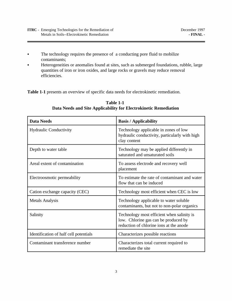
C The technology requires the presence of a conducting pore fluid to mobilizecontaminants;
C Heterogeneities or anomalies found at sites, such as submerged foundations, rubble, largequantities of iron or iron oxides, and large rocks or gravels may reduce removalefficiencies.
Table 1-1 presents an overview of specific data needs for electrokinetic remediation.
Table 1-1 Data Needs and Site Applicability for Electrokinetic Remediation
Data Needs Basis / Applicability
Hydraulic Conductivity Technology applicable in zones of lowhydraulic conductivity, particularly with highclay content
Depth to water table Technology may be applied differently insaturated and unsaturated soils
Areal extent of contamination To assess electrode and recovery wellplacement
Electroosmotic permeability To estimate the rate of contaminant and waterflow that can be induced
Cation exchange capacity (CEC) Technology most efficient when CEC is low
Metals Analysis Technology applicable to water solublecontaminants, but not to non-polar organics
Salinity Technology most efficient when salinity islow. Chlorine gas can be produced byreduction of chlorine ions at the anode
Identification of half cell potentials Characterizes possible reactions
Contaminant transference number Characterizes total current required toremediate the site

ITRC - Emerging Technologies for the Remediation of December 1997Metals in Soils--Electrokinetic Remediation - FINAL -
Data Needs Basis / Applicability
4
Porewater pH Affects contaminant valence state and itstendency to precipitate out of solution
2.0 APPROACHES TO ELECTROKINETICS TECHNOLOGY
2.1 General
The electrokinetic transport phenomena pertinent to in-situ remediation include electroosmosis(movement of water in response to an electric field), electrophoresis (movement of a chargedparticle or colloid in an electric field), and electromigration (movement of solute ions in theelectric field). Electrokinetic remediation is accomplished by implanting electrodes in the soil withapplication of a relatively small direct electrical current across the electrodes. Ions in solution willmigrate toward the electrode of opposite charge by electromigration. Experimental resultsindicate that the electromigration rates depend significantly on the soil pore water current density.The process efficiency is not as dependent on the fluid permeability of soil as it is on the porewater electrical conductivity and the path length through the soil. Both of these characteristicsare functions of the soil moisture content.
Removal of contaminants at the electrode may be accomplished by several means, includingelectroplating, precipitation or co-precipitation at the electrode, pumping of water near theelectrode, or complexing with ion exchange resins (PRC, 1996). An alternate method suggestedis adsorption into the electrode. This may be feasible because some ionic species will changevalence near the electrode (depending on the soil pH) making them more likely to adsorb.
The direction and quantity of contaminant movement is influenced by contaminant concentration,charge or ionic character (anions versus cations), soil type and structure, interfacial chemistry, andcurrent density in the soil pore water. For the process to work, the soil moisture content must beabove a minimum value. This minimum moisture content can be estimated from the residualmoisture content of a soil, also called "immobile water.” Preliminary results indicate that theoptimum soil moisture content for electromigration is less than saturation, due to competingeffects of tortuosity and pore water content. This value may be between 10 and 20%.
2.2 Site Screening
Before electrokinetic remediation is undertaken at a site, a number of field and laboratory

ITRC - Emerging Technologies for the Remediation of December 1997Metals in Soils--Electrokinetic Remediation - FINAL -
5
screening tests must be conducted to determine if the site is amenable to the technology:
C Field conductivity surveys: The natural spatial conductivity variability should bedelineated because buried metallic or insulating material can induce variability in theelectrical conductivity of the soil and, therefore, the voltage gradient. In addition, it isimportant to assess if there are deposits that exhibit very high electrical conductivity,where the process may be inefficient.
C Chemical analysis of water: The pore water in the vadose zone should be analyzed fordissolved major anions and cations, as well as for the concentration of the contaminant(s). Electrical conductivity and pH of the pore water should be measured, and an estimate ofthe contaminant transference number should be made.
C Chemical analysis of soil: The buffering capacity and geochemistry of the soil should bedetermined.
2.3 Current Applications
Electrokinetic remediation technology has recently taken significant strides. Electrokinetics Inc. ofBaton Rouge, LA has completed large-scale pilot studies using spiked and naturally contaminatedsoil deposits under the USEPA SITE program. In collaboration with the US Army WaterwaysExperiment Station, Electrokinetics Inc. is currently carrying out a field study of extracting leadfrom soils at a Firing Range that belongs to the US Army. Other vendors have begun utilizingelectrokinetics in the field, but data on completed projects is not yet available.
3.0 RESEARCH AND DEVELOPMENT—FUTURE NEEDS
Electrokinetic extraction of metals from soils has undergone bench-scale and pilot-scale testing. As noted above, premature precipitation of metal species close to the cathode compartment hasbeen a bottleneck for the process. Acetic acid depolarization techniques and other depolarizationschemes have been developed (EK, 1993) to circumvent this problem. Extraction of heavy metalsby bench and pilot-scale tests from ‘real world’ soils retrieved from numerous sites demonstratesthat the technology may be applied efficiently and cost-effectively. Currently, field demonstrationstudies are ongoing in the US.
Electrokinetic remediation is a developing technology. Projected performance will be determinedafter a predictive model for migration rates is developed. In such a predictive model, migrationrate is a function of moisture content, sand grain size, ionic mobility, pore water, current density,

ITRC - Emerging Technologies for the Remediation of December 1997Metals in Soils--Electrokinetic Remediation - FINAL -
6
contaminant concentration, and total ionic concentration. More field work is needed to validatethe results of any models that are developed.
4.0 CASE STUDIES AND RESULTS
4.1 USEPA Site Program
Three pilot-scale studies were conducted by Electrokinetic Inc. under the USEPA SITE program;two tests using kaolinite spiked with lead at initial concentrations of 850 mg/kg and 1,500 mg/kg,and another using fine sand and kaolinite mixture spiked with lead at 5,322 mg/kg. The kaoliniteused had lead adsorption capacity of about 1,100 mg/kg. Lead nitrate salt was used as the sourceof lead. Tap water was used both as the catholyte and the anolyte. Other details of testing arepresented by Alshawabkeh and Acar (3) and EK (5). More than 90% of the lead in the soil istransported across to the cathode compartment. Lead prematurely precipitates close to thecathode compartment at its hydroxide solubility value if the chemistry of the electrolyte at theelectrodes is not altered or controlled (unenhanced electrokinetic remediation) . One objective ofthese pilot-scale tests was to formalize and validate the principles of multi-species transport underelectric fields. An appreciation of the relation between the mechanics and chemistry is only possible when precipitation close tothe cathode compartment is allowed. Therefore, pilot-scale tests did not employ enhancementtechniques.
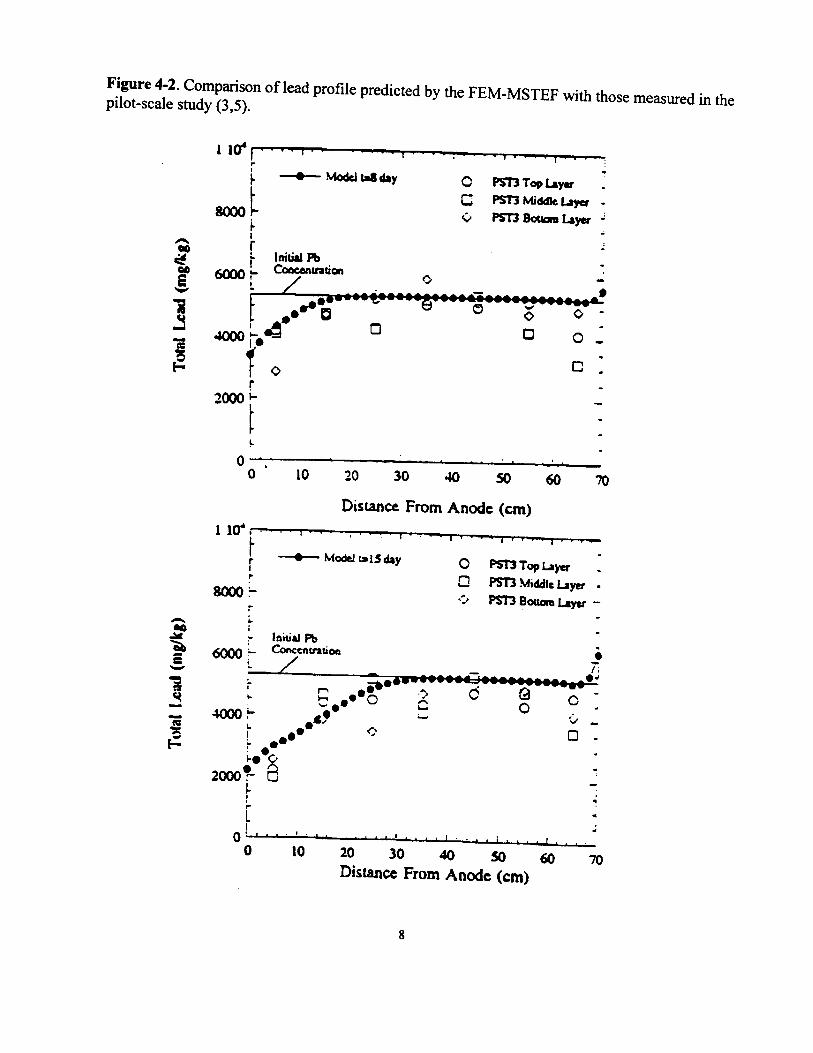
The development of the theoretical formalisms pertaining to multi-species transport under electricfields and the preparation of the associated numerical model and design/analysis packages aresupported by the USEPA under the Gulf Coast Hazardous Substance Research Center program atLamar University. The total lead profile predictions of the model pertinent to the specific initialand boundary conditions in the pilot-scale test are given on the following page in Figure 4-1. Thelead and the acid generated by the electrolysis reactions at the anode were released into the porefluid either by dissolution or by the aqueous phase reactions. They then travel towards thecathode compartment under the multi-species transport phenomena in soils under electric fields.Lead precipitates close to the cathode compartment at its hydroxide solubility value with theincrease in the hydroxide concentration due to the prevailing cathodic reaction. The 50 daypredictions shown in Figure 4-1 are compared with the pilot-scale test results in Figure 4-2. Theagreement between the theoretical model and the pilot-scale test results demonstrate that theprinciples of the process are well rationalized and understood. The design analysis package whichwill include the generalized model is being developed through a joint effort betweenElectrokinetics Inc. and US Army Waterways Experiment Station.

7
The need to overcome the problem of precipitation close to the cathode compartment promptedElectrokinetics Inc. and the US Army Waterways Experiment Station to evaluate the feasibility ofemploying different techniques to enhance the process. The objective of the study was to promotetransport of the positively charged species into the catholyte where they could be removed eitherby Figure 4-1. Prediction of total lead concentration across the electrodes using the Finite ElementModel for Multi-Species Transport in Soils under Electrical Fields (FEM-MTSE) [Boundary andInitial Conditions pertinent to the Pilot-Scale Study are employed; 100 elements are used] (3,5).


ITRC - Emerging Technologies for the Remediation of December 1997Metals in Soils--Electrokinetic Remediation - FINAL -
9
electro deposition, membrane separation, or ion exchange. Acar and Alshawabkeh (1) discuss theneed for enhancement and propose different enhancement techniques to prevent the encounteredprecipitation. The solubility of the species by the anodic acid and the migration under electricalfields are important considerations in electrokinetic remediation. The most soluble species willcome out in solution first and be transported towards the respective electrode.
Although the acetic acid depolarization technique is successfully being used in the remediation oflead, chromium, zinc and other heavy metals from soils in the US and Europe, the techniquegenerates significant amounts of liquid requiring secondary processing. Electrokinetics Inc. hasdeveloped an electrode system (CADEX(TM)) that promotes electrodeposition of the species andminimizes the need for secondary processing.
In collaboration with the US Army Waterways Experiment Station, Electrokinetics Inc. iscurrently conducting a field-scale demonstration study at Fort Polk, Louisiana. The site is locatedin a creek bed. The surface deposits within the first two feet are contaminated with lead atconcentrations of 3,500 mg/ kg (+/- 500 mg/kg). The lead in the deposits leached from the bulletsin a firing range from years of exposure to the environment. Preliminary chemical speciation andcorrosion studies indicate that minute quantities of lead leach from the individual particulates andthe contamination is mainly due to the quantity of the bullets left at the site. An area of about2,000 ft2 is being processed. CADEX(TM) electrode system is being used for the project. Onsiteremediation is expected to continue for about six months to a year, with a goal of attaining levelsof 100 mg/kg or less across the site. USEPA will conduct an independent evaluation of thedemonstration study through the SITE program.
4.2 Electrokinetic Remediation of Chromium at Sandia Laboratories- Field Study
The Chemical Waste Landfill (CWL) was a chemical disposal site for Sandia NationalLaboratories in Albuquerque, New Mexico from 1962 to 1985. During this time, chemicals wereseparated by type and disposed in unlined trenches. It is estimated that over 4290 gallons ofchromic sulfuric acid solution was disposed into unlined chromic acid pits. The chromium wasdisposed in hexavalent form. The very low organic fraction present in the native soil suggests thatthe chromium should remain in the hexavalent form. This anionic hexavalent chromium adsorbsweakly to the soil beneath the landfill, resulting in a mobile contaminant that has apparentlymigrated to a depth of at least 23 meters below the ground surface (15).
An electrokinetic process was demonstrated in one of these unlined chromic acid pits during thesummer and fall of 1996. The purpose of the demonstration was to show that an electrokineticprocess could be used to extract chromate contamination from in situ unsaturated soils withoutsignificantly altering the soil moisture content. The treatment zone was located in a 3.7 meter

ITRC - Emerging Technologies for the Remediation of December 1997Metals in Soils--Electrokinetic Remediation - FINAL -
10
square over the area exhibiting the greatest degree of contamination (see Figure 3 on thefollowing page).
The electrode layout and spacing were chosen to produce as uniform (or planar) an electric fieldas possible while minimizing the effects of soil heating. The active treatment horizon was 1.8meters thick, placed at 2.4 to 4.3 meters below the surface. A total of fifteen electrodes wereinstalled for the demonstration. During the installation of the electrodes, numerous soil sampleswere collected to characterize the site. One row of five anodes were placed in the center of thepit, and two rows of five cathodes were placed six feet to the north and south of the row ofanodes near the edge of the chromate plume.
The electrode assemblies used are a unique, patented design using porous ceramic casings filledwith electrolyte solution in which a drive electrode is deployed. The electrolyte solution is heldunder tension inside the porous ceramic housing by an applied vacuum which prevents saturationof the adjacent soil. Application of an electric potential to the electrodes causes chromate anionsin the soil porewater to migrate toward the anode electrode assemblies. The chromate migratesthrough the porous ceramic into the electrolyte solution. During operation, a small amount of theelectrolyte solution is periodically pumped out of the anode assembly and into waste barrels. Thiseffluent stream is sampled and analyzed to determine the concentration and removal rate ofchromate.
The soil samples collected during electrode casing installation were extracted with deionizedwater. The water mass to soil mass ratio was 2:1. The soil water mixture was shaken for onehour and allowed to settle. Supernate was recovered and passed through a 0.45 µm filter. ThepH and electrical conductivity of the extract was measured and the chromate concentration wasdetermined spectrophotometrically by the highly sensitive and selective diphenylcarbazide method. Samples from the effluent of each electrode assembly were collected daily and the amount ofeffluent removed from each electrode was monitored. The pH and electrical conductivity of theaqueous samples was measured and the chromate concentration was determinedspectrophotometrically by the same diphenylcarbazide method. The electrical current passedthrough each electrode was measured and datalogged.
In Figure 4-4, the transference number of chromate in the effluent of each of the five anodes isplotted against time for the first 100 hours of the demonstration. In Figure 4-5, the cumulativecharge of chromate removed (in coulombs) from each anode is plotted against the cumulativeelectrical charge (in amp-hours) passed through each anode. The transference number forchromate is the slope of these curves. Both figures are found on the following pages.


ITRC - Emerging Technologies for the Remediation of December 1997Metals in Soils--Electrokinetic Remediation - FINAL -
13
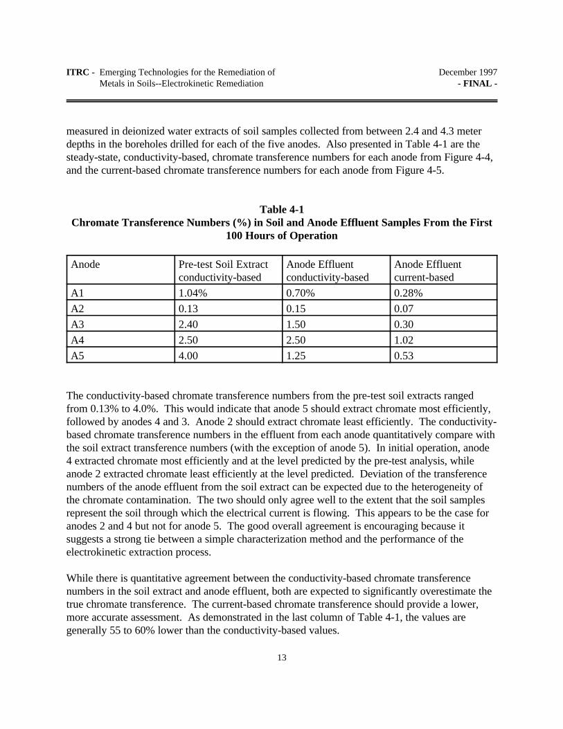
measured in deionized water extracts of soil samples collected from between 2.4 and 4.3 meterdepths in the boreholes drilled for each of the five anodes. Also presented in Table 4-1 are thesteady-state, conductivity-based, chromate transference numbers for each anode from Figure 4-4,and the current-based chromate transference numbers for each anode from Figure 4-5.
Table 4-1Chromate Transference Numbers (%) in Soil and Anode Effluent Samples From the First
100 Hours of Operation
Anode Pre-test Soil Extractconductivity-based
Anode Effluentconductivity-based
Anode Effluentcurrent-based
A1 1.04% 0.70% 0.28%
A2 0.13 0.15 0.07
A3 2.40 1.50 0.30
A4 2.50 2.50 1.02
A5 4.00 1.25 0.53
The conductivity-based chromate transference numbers from the pre-test soil extracts rangedfrom 0.13% to 4.0%. This would indicate that anode 5 should extract chromate most efficiently,followed by anodes 4 and 3. Anode 2 should extract chromate least efficiently. The conductivity-based chromate transference numbers in the effluent from each anode quantitatively compare withthe soil extract transference numbers (with the exception of anode 5). In initial operation, anode4 extracted chromate most efficiently and at the level predicted by the pre-test analysis, whileanode 2 extracted chromate least efficiently at the level predicted. Deviation of the transferencenumbers of the anode effluent from the soil extract can be expected due to the heterogeneity ofthe chromate contamination. The two should only agree well to the extent that the soil samplesrepresent the soil through which the electrical current is flowing. This appears to be the case foranodes 2 and 4 but not for anode 5. The good overall agreement is encouraging because itsuggests a strong tie between a simple characterization method and the performance of theelectrokinetic extraction process.
While there is quantitative agreement between the conductivity-based chromate transferencenumbers in the soil extract and anode effluent, both are expected to significantly overestimate thetrue chromate transference. The current-based chromate transference should provide a lower,more accurate assessment. As demonstrated in the last column of Table 4-1, the values aregenerally 55 to 60% lower than the conductivity-based values.

ITRC - Emerging Technologies for the Remediation of December 1997Metals in Soils--Electrokinetic Remediation - FINAL -
14
5.0 REGULATORY ISSUES RELATED TO ELECTROKINETICS
From a regulatory viewpoint, the following concerns need to be addressed:
C What is an acceptable time frame for clean-up?
Electrokinetic technologies may take longer than conventional technologies due to the fact that astarget levels become low (<100 mg/kg), the operational efficiency of the technology decreases. The technology may be most applicable at sites where long term remediation is being considered.
C How will confirmatory sampling be conducted due to the nature of the technology?
Application of electrokinetics may result in residual pockets of contamination in close proximityto soils that have been completely remediated. Contaminant concentrations may fluctuate widelyacross extremely small distances (centimeters). As such, sample locations and frequencies mustbe chosen carefully and conservatively.
C What long and short term impacts may be imposed on the site and surroundingenvironment?
There is some concern about the condition of site soils once remediation is complete. Regulatorsare concerned that soil may not be able to sustain growth due to the chemical, physiological andbiological impacts on soil media due to the application of electrical currents. The technology maybe more applicable at industrial sites where the concerns noted above may not be an issue.
C To what extent do site heterogeneities affect efficiency rates? How can theseanomalies be assessed by regulators?
Electrokinetic technologies work best at sites with homogeneous soils and contamination. Hotspots may pose a problem, as with nearly any remedial technology. Areas with no contaminationmay also be of concern, due to the creation of “dead zones” where transference does not occur. A large degree of small-scale site characterization may be needed to address system design andcompliance sampling issues.
C Prolonged application of direct current can significantly modify soil properties. Willacidic fronts at the anodes or strong basic conditions at the cathodes be created?
If soils are left in place after remediation, either of the situations mentioned above may occur. If
ITRC - Emerging Technologies for the Remediation of December 1997Metals in Soils--Electrokinetic Remediation - FINAL -
15
the metals are removed below the threshold limit but the pH of the residual soils is either very lowor very high, RCRA waste restrictions may still apply. The application and design of the systemmust take this into account.
C Most of the time, soils near cathodes will be excavated (or groundwater will need tobe disposed of). Will soils near anodes have to be excavated as well (and/orgroundwater re-circulated)?
While this is largely an engineering concern, regulators and problem holders must be aware of theneed for removal of the contaminants through either groundwater recirculation or excavation. The final waste stream will need to be disposed in accordance with applicable regulations.
The ITRC plans to monitor the development of this technology and address these and otherregulatory issues in a “Technical and Regulatory Guidance” document, for deployment ofelectrokinetics technologies.
6.0 COST
The cost of electrokinetic remediation is dependent on specific chemical and hydraulic propertiesof soils present at the site. Ongoing pilot-scale field studies indicate that the energy consumptionin extracting heavy metals from soils may be approximately 500 kW-hr / m3 or more at anelectrode spacing of 1.0-1.5 m. The direct cost would be approximately $25 / m3, or about $0.05/ kW-hr, at this level of energy consumption. The energy consumption rate can be loweredsignificantly if cathodic depolarization techniques are used since no low conductivity zone wouldbe formed around the cathode compartment (Acar et al., 1993). The total power consumed isdirectly proportional to the time required for migration to achieve the cleanup level desired. Atypical migration rate would be approximately 2.5 cm per day. For an electrode spacing of 2 to 3m, the corresponding time frame for remediation would be approximately 100 days. An estimatedprice range per unit of soil treated is given as follows:
Electro-Petroleum, Inc. $60-$110 per yd3 (faxed information)Dupont R&D $65 per yd3
Electrokinetics, Inc. $20-$100 per yd3
Geokinetics International $75-$225 per yd3
Price estimates do not always include indirect costs associated with remediation, such asexcavation, permits, and treatment of residues. Price comparisons should be based on comparablesites and scopes of remediation activities for each vendor. Factors which have a significant effect
ITRC - Emerging Technologies for the Remediation of December 1997Metals in Soils--Electrokinetic Remediation - FINAL -
16
on unit price are:
C Initial and target contaminant concentrationsC Concentration of non-target ions, or conductivity of pore waterC Soil characteristics and moisture contentC Quantity of wasteC Depth of contaminationC Residual waste handling and processingC Site preparation requirementsC Electricity and labor rates
7.0 PUBLIC AND STAKEHOLDER CONCERNS
Electrokinetics shows promise as a potentially effective technology for the remediation of metalcontaminated soils. Because electrokinetics is an in-situ technology which requires relatively littlesite disturbance and limited use of heavy equipment for excavation and off-site disposal of soil, itis expected to meet with positive response from responsible parties and community stakeholdersassociated with specific sites. Electrokinetic methods have a relatively long research history(since the 1930s), and have been investigated for contaminant application since the early to mid1980s. It is important to note, however, that there are still many questions on the technologybeing addressed by researchers and regulatory agencies
Electrokinetics’ applicability can often be site-specific and may pose concerns pertaining to themobility of compounds, metals and contaminants present. For public or community stakeholders,the addition of water in unsaturated soils might be a concern due to the potential of hydraulicallywashing contaminants out of the capture zone. An unsaturated soil extraction electrode systemmay need to be designed to minimize this problem.
Secondary impacts of treatments or mechanical processes used in support of electrokineticmethods must be disclosed during all stages of project development and mitigated to the greatestdegree. For example:
C What are the potential impacts of materials used in electroplating or ion exchange?C What energy sources are being used, and what impact will they have on the environment?
Technology developers must address these and other concerns, to maximize the range of siteswhere electrokinetics technologies may be used.

ITRC - Emerging Technologies for the Remediation of December 1997Metals in Soils--Electrokinetic Remediation - FINAL -
17
8.0 CONCLUSIONS
Electrokinetic extraction of metals from soils has undergone bench-scale testing and pilot-scaletesting. A theoretical model has been developed and its numerical implementation has beencompleted. The predictions of this model compared with the results of the pilot-scale studiesdemonstrate that the principles of the technique have been well rationalized. Currently, the modelis being generalized and additional information is being incorporated. Construction guidelines willbe written upon completion of the field studys. When cost-effectiveness and technical feasibility ofother remedial options prohibit their use, electrokinetic remediation may offer an alternative atsites contaminated with inorganic species. The technique also is in the process of being scrutinizedand developed for injection, specifically to enhance the in-situ bioremediation of organic speciesthrough injection of process additives, nutrients and microorganisms.

ITRC - Emerging Technologies for the Remediation of December 1997Metals in Soils--Electrokinetic Remediation - FINAL -
18
9.0 REFERENCES
1. Acar, Y.B., Alshawabkeh, A. Principles of Electrokinetic Remediation . EnvironmentalScience and Technology, vol. 27, n. 13, pp. 2638-December 1993.
2. Acar, Y. B., Gale R. J., Alshawabkeh, A., Marks, R. E., Puppala, S., Bricka, M., Parker,R. "Electrokinetic Remediation: Basics and Technology Status," Journal of Hazardous Materials,Elsevier Science B.V., Amsterdam, Netherlands, 40(3), February 1995, pp. 117-137.
3. Alshawabkeh, A., Acar, Y. B., "Electrokinetic Remediation: I. Pilot-Scale Tests; II.Theory" Journal of Geotechnical and Geoenvironmental Engineering, ASCE, (in review)
4. EK(1994). An Investigation of Selected Enhancement Techniques in ElectrokineticRemediation, Report submitted to US Army Waterways Experiment Station, Electrokinetics Inc.,Baton Rouge, Louisiana, 1993, 160 p.
5. EK(1995). Theoretical and Experimental Modeling of Removing Contaminants from Soilsby an Electrical Field, Report submitted to USEPA by Electrokinetics Inc., Baton Rouge,Louisiana, 375 p. (in press).
6. Lageman, R.; Wieberen, P.; Seffinga, G. Electro-Reclamation:Theory and Practice.Chemistry and Industry, Society of Chemical Industry, London, pp. 585-590, 1989.
7. Shapiro, A. P.; Probstein, R.F. (1993) _ Removal of Contaminants from Saturated Clay byElectroosmosis," Environmental Science and Technology, 1993, 27 (2), pp. 283-291.
8. USEPA (1994), “Selection of Control Technologies for Remediation of SoilContaminated with Arsenic, Cadmium, Chromium, Lead, or Mercury.” Revised DraftEngineering Bulletin. January 31.
9. USEPA (1994), “In Situ Vitrification Treatment.” Engineering Bulletin. October.
10. PRC Environmental Management, Inc. (1996), “Recent Developments for In-SituTreatment of Metal Contaminated Soils (Review Draft)”, Prepared for: USEPA, Office of SolidWaste and Emergency Response, Technology Innovation Office, Washington, D.C. August 12.
11. USEPA (1995), “Contaminants and Remedial Options at Selected Metal-ContaminatedSites.” Office of Research and Development. July 1995.

ITRC - Emerging Technologies for the Remediation of December 1997Metals in Soils--Electrokinetic Remediation - FINAL -
19
12. Lindgren, E.R., M.W. Kozak, "Electrokinetic Remediation of Contaminated Soils: anUpdate", in Waste Management '92, 1992 (Technology and Programs for Radioactive WasteManagement and Environmental Restoration); pp 1309
13. Lindgren, E.R., E.D. Mattson, and M.W. Kozak, "Electrokinetic Remediation ofUnsaturated Soils", Presented at the I&EC Special Symposium of the American ChemicalSociety, Atlanta, GA, September 1992; (Draft copy, submitted for peer review).
14. US Department of Energy-MWLID, "Electrokinetic Remediation", FY92 Technical TaskDescription, TTP No. ALZE21J2, October 10, 1991.
15. Lindgren, E.R. and E.D. Mattson, “Electrokinetic Demonstration at Sandia NationalLaboratories: Use of Transference Numbers for Site Characterization and Process Evaluation,” inProceedings of Waste Management Conference, Tuscon, AZ, 1997
16. Geokinetics (1997), “Electrokinetic Remediation -- Some Lessons From European and USCommercialization,” Confidential facsimile transmittal to Daniel Sogorka. ITRC “Metals in SoilsWorkteam” Technical POC. June 1997, 8 pages.

APPENDIX A
Acronyms

(A-1)
ACRONYMS
CEC Cation Exchange CapacityCWL Chemical Waste LandfillDC Direct CurrentFEM-MTSE Finite Element Model for Multi-Species Transport in Soils under Electrical FieldsIINERT In-Place Inactivation and Natural Ecological Restoration TechnologiesITRC Interstate Technology and Regulatory Cooperation Working GroupLA State of Louisianamg/kg milligrams per kilogramRCRA Resource Conservation and Recovery ActRMIES RMI Environmental Services, Inc.RTDF Remediation Technologies Development ForumUSEPA United States Environmental Protection Agency

APPENDIX B
ITRC Work Team ContactsITRC Fact Sheet
Product Information User Survey

(B-1)
ITRC METALS IN SOILS TEAM PROJECT CONTACTS
Brian Sogorka 1997 Team Leader, Soil Washing Project LeaderNJ Dept. of Environmental ProtectionTrenton, NJ 08625P 609-633-1344F [email protected]
Helge GabertElectrokinetics Project LeaderUtah Department of Environmental QualitySalt Lake City, UT 84114-4880P 801-538-6170F [email protected]
Dib GoswamiPhytoremediation Project LeaderWashington State Dept. of EcologyKennewick, WA 99336P 509-736-3015F [email protected]
Bill BertiInsitu Stabilization Project LeaderDuPont Central Research & DevelopmentGlasgow, DE 19702P 302-451-9224F [email protected]
Dan SogorkaMetals Team Project SupportColeman Research CorporationGermantown, MD 20874P 301-515-6910F [email protected]