EMC TEST REPORT StangSat CubeSat Program - … Rev. Basic 29 August 2013 EMC TEST REPORT StangSat...
23
EML-0001-QUL Rev. Basic 29 August 2013 EMC TEST REPORT StangSat CubeSat Program ENGINEERING SERVICE CENTER ELECTROMAGNETIC LABORATORY Kennedy Space Center, FL 32815-0233 JOHN F. KENNEDY SPACE CENTER, NASA https://ntrs.nasa.gov/search.jsp?R=20140017857 2018-07-01T17:47:20+00:00Z
Transcript of EMC TEST REPORT StangSat CubeSat Program - … Rev. Basic 29 August 2013 EMC TEST REPORT StangSat...
EML-0001-QUL Rev. Basic
29 August 2013
EMC TEST REPORT
StangSat
CubeSat Program
ENGINEERING SERVICE CENTER ELECTROMAGNETIC LABORATORY Kennedy Space Center, FL 32815-0233
JOHN F. KENNEDY SPACE CENTER, NASA
https://ntrs.nasa.gov/search.jsp?R=20140017857 2018-07-01T17:47:20+00:00Z
EML-0001-QUL Rev. Basic
29 August 2013
Page 2 of 23
EMC TEST REPORT
StangSat
CubeSat Program
Originator: Reviewers:
Lynne M. Carmody James E. Stanley Electromagnetic Lab Electromagnetic Lab Supervisor EMI Engineer
Gerard P. Floyd ENG Integration Peter S. Aragona NASA Electromagnetic Lab Manager
EML-0001-QUL Rev. Basic
29 August 2013
Page 3 of 23
Revision History
Revision Date Author(s) Changes
Original August 29, 2013 Lynne M. Carmody Document Release
EML-0001-QUL Rev. Basic
29 August 2013
Page 4 of 23
TABLE OF CONTENTS
1 INTRODUCTION ........................................................................................................ 8
1.1 Unit under Test (UUT) Description ................................................................................... 8
2 PURPOSE ............................................................................................................... 11
3 SCOPE .................................................................................................................... 11
4 TEST METHOD ........................................................................................................ 12
5 RESULTS ................................................................................................................ 13
5.1 Bonding .............................................................................................................................. 13
5.2 Testing Results ................................................................................................................... 13
6 REFERENCES .......................................................................................................... 13
A RE102 RADIATED EMISSIONS, ELECTRIC FIELD ................................................... 14 A.1 RE102 Equipment .......................................................................................................... 14
A.2 Bandwidths and Dwell Times ............................................................................................ 15 A.3.1 RE102 Verification ....................................................................................................... 16 A.3.2 Test Data ...................................................................................................................... 18 A.3.3 Photos .......................................................................................................................... 19
EML-0001-QUL Rev. Basic
29 August 2013
TABLE OF FIGURES
FIGURE 1: STANGSAT TEST SETUP .......................................................................................................... 9 FIGURE 2: STANGSAT TEST SETUP “TOP VIEW” ......................................................................................... 9 FIGURE 3: CAMERA VIEW OF STANGSAT DURING TEST ............................................................................. 10 FIGURE 4: DIAGRAM OF TEST SET‐UP .................................................................................................... 11 FIGURE 5: RE102 LIMIT FOR AIRCRAFT AND SPACE SYSTEMS APPLICATIONS ................................................. 12 FIGURE A.3‐1: RE102 ACTIVE ROD VERIFICATION .................................................................................. 16 FIGURE B.3‐2: RE102 SYSTEM VERIFICATION ........................................................................................ 17 FIGURE A.3‐3: RE102 TEST DATA 2 MHZ TO 8000 MHZ VERTICAL POLARIZATION ..................................... 18 FIGURE A.3‐4: RE102 TEST DATA 30 MHZ TO 18000 MHZ HORIZONTAL POLARIZATION ............................ 18 FIGURE A.3‐5: RE102 ACTIVE ROD ANTENNA SETUP .............................................................................. 19 FIGURE A.3‐7: RE102 BICONICAL ANTENNA SETUP, HORIZONTAL ............................................................. 20 FIGURE A.3‐8: RE102 BICONICAL ANTENNA SETUP, VERTICAL ................................................................. 20 FIGURE A.3‐9: RE102 BIG HORN ANTENNA SETUP, HORIZONTAL ............................................................. 21 FIGURE A.3‐10: RE102 BIG HORN ANTENNA SETUP, VERTICAL ................................................................ 21 FIGURE A.3‐12: RE102 SMALL HORN ANTENNA SETUP, VERTICAL ............................................................ 22
EML-0001-QUL Rev. Basic
29 August 2013
Page 6 of 23
TABLE OF TABLES
TABLE 1: STANGSAT MIL‐STD‐461F REQUIREMENTS ............................................................................................... 8 TABLE 5.2: TESTING RESULTS .................................................................................................................. 13 TABLE A.1: RE102 EQUIPMENT LIST .................................................................................................... 14 TABLE A.2: RE102 BANDWIDTHS AND DWELL TIMES .............................................................................. 15 TABLE A.3‐1: RE102 ACTIVE ROD VERIFICATION, PEAKS ......................................................................... 16 TABLE A.3‐2: RE102 VERIFICATION 2MHZ TO18000MHZ, PEAKS .......................................................... 17
EML-0001-QUL Rev. Basic
29 August 2013
Page 7 of 23
Abstract This report documents the Electromagnetic Interference E M I testing performed on the StangSat; the unit under test (UUT). Testing was per the requirements of MIL STD-461F. The UUT was characterized and passed the radiated emissions (RE102 limit for Spacecraft) testing.
EML-0001-QUL Rev. Basic
29 August 2013
Page 8 of 23
1 Introduction
The following tests (See Table 1) were requested for the StangSat. The testing was performed to MIL-STD-461F.
Table 1: StangSat MIL-STD-461F Requirements
Test Method
Test Description
Frequency Range
RE102 Radiated Emissions, Electric Field, Space System, Fixed Wing Internal Limit, ≥ 25m Nose to Tail
2 MHz to 18 GHz
MIL-STD-461 was established to determine the requirements for the control of electromagnetic interference characteristics of subsystems and equipment for applicable Military and Aerospace Divisions. MIL-STD-461 deals with two basic areas, electromagnetic effects that are conducted and radiated. Each of these areas has two different categories, emissions and susceptibility. MIL-STD-461 Rev F establishes specific requirements and test methods for each set and subset: Conducted Emissions, Conducted Susceptibility, Radiated Emissions and Radiated Susceptibility. MIL-STD-461 Rev. F EMI Testing is performed to determine compliance of the StangSat to the requirements listed in Table 1. The EMI testing confirms there is a high level of confidence the StangSat will function properly and not interfere with other systems and equipment.
1.1 Unit under Test (UUT) Description
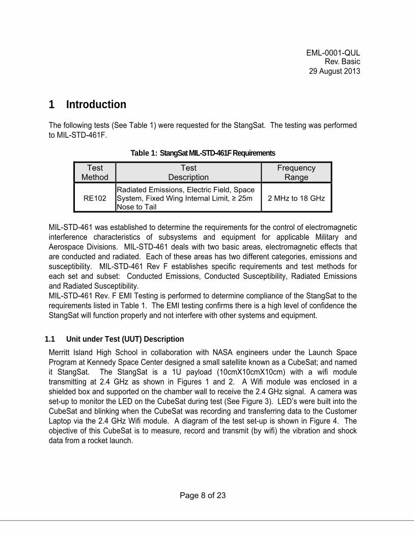
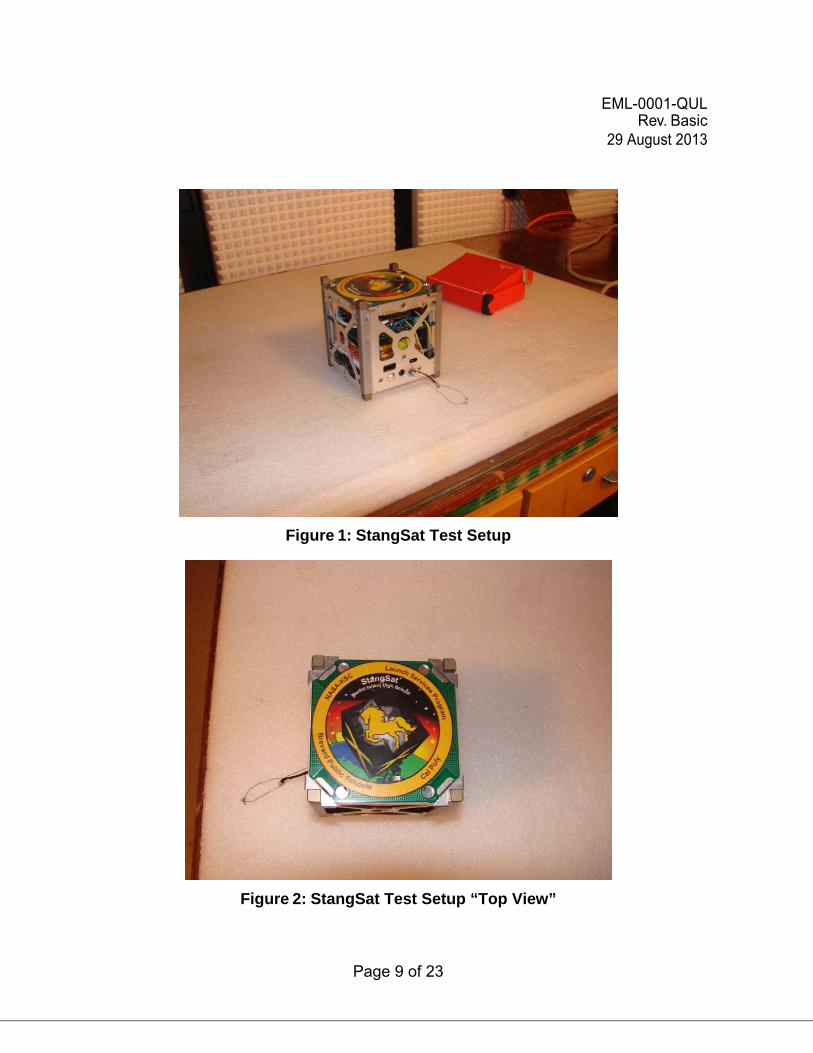
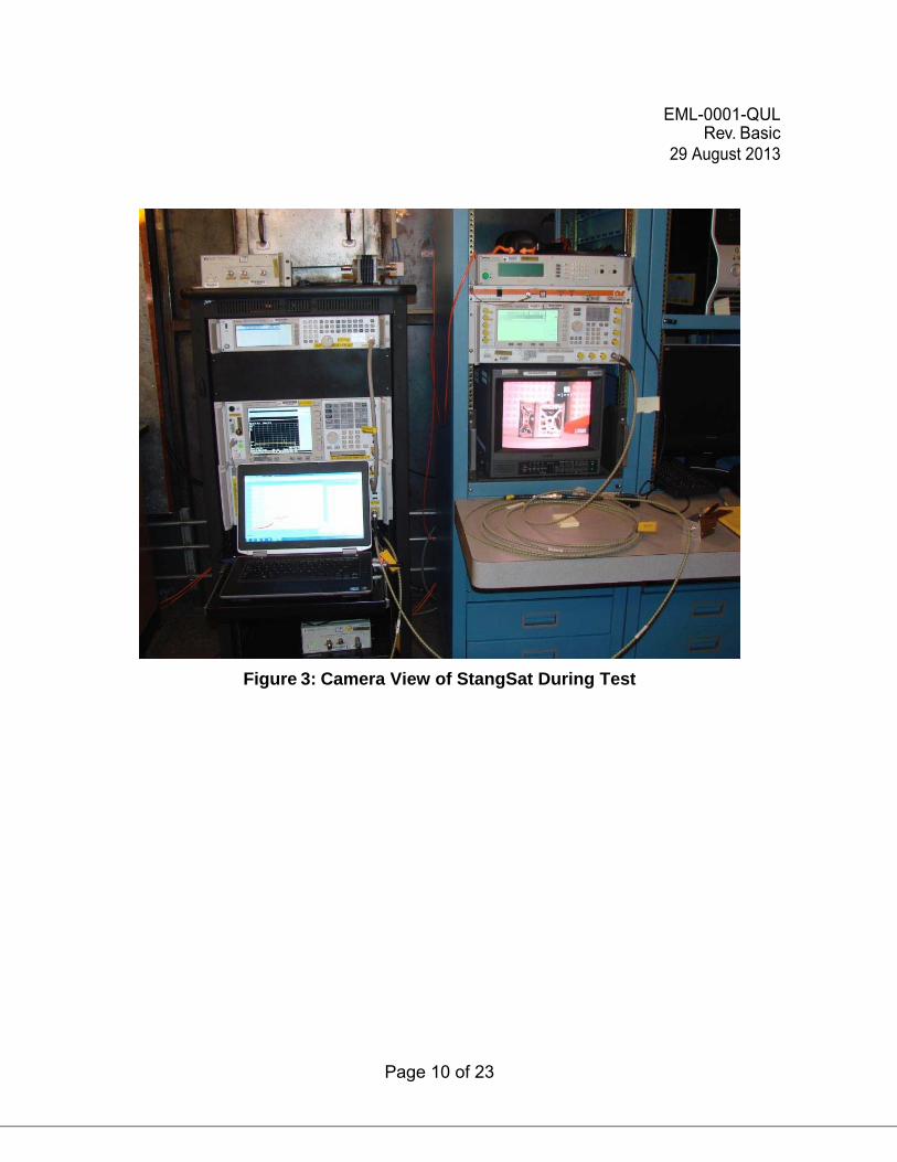
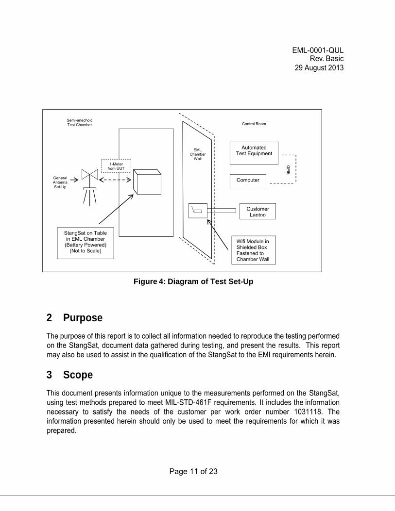
Merritt Island High School in collaboration with NASA engineers under the Launch Space Program at Kennedy Space Center designed a small satellite known as a CubeSat; and named it StangSat. The StangSat is a 1U payload (10cmX10cmX10cm) with a wifi module transmitting at 2.4 GHz as shown in Figures 1 and 2. A Wifi module was enclosed in a shielded box and supported on the chamber wall to receive the 2.4 GHz signal. A camera was set-up to monitor the LED on the CubeSat during test (See Figure 3). LED’s were built into the CubeSat and blinking when the CubeSat was recording and transferring data to the Customer Laptop via the 2.4 GHz Wifi module. A diagram of the test set-up is shown in Figure 4. The objective of this CubeSat is to measure, record and transmit (by wifi) the vibration and shock data from a rocket launch.
EML-0001-QUL Rev. Basic
29 August 2013
Page 9 of 23
Figure 1: StangSat Test Setup
Figure 2: StangSat Test Setup “Top View”
EML-0001-QUL Rev. Basic
29 August 2013
Page 10 of 23
Figure 3: Camera View of StangSat During Test
EML-0001-QUL Rev. Basic
29 August 2013
Page 11 of 23
Figure 4: Diagram of Test Set-Up
2 Purpose The purpose of this report is to collect all information needed to reproduce the testing performed on the StangSat, document data gathered during testing, and present the results. This report may also be used to assist in the qualification of the StangSat to the EMI requirements herein.
3 Scope This document presents information unique to the measurements performed on the StangSat, using test methods prepared to meet MIL-STD-461F requirements. It includes the information necessary to satisfy the needs of the customer per work order number 1031118. The information presented herein should only be used to meet the requirements for which it was prepared.
Wifi Module in Shielded Box Fastened to Chamber Wall
StangSat on Table in EML Chamber
(Battery Powered) (Not to Scale)
EML Chamber
Wall
General Antenna Set-Up
1-Meter from UUT
Semi-anechoic Test Chamber Control Room
Automated Test Equipment
Computer
GP
IB
Customer Laptop
EML-0001-QUL Rev. Basic
29 August 2013
Page 12 of 23
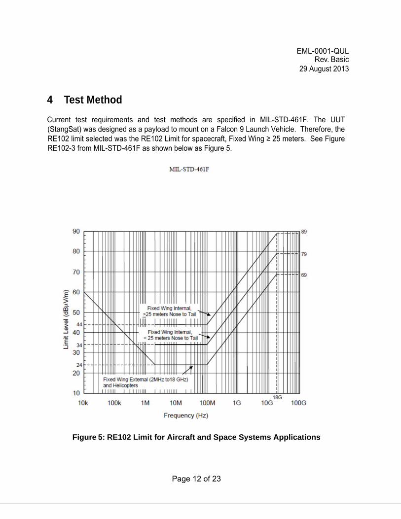
4 Test Method
Current test requirements and test methods are specified in MIL-STD-461F. The UUT (StangSat) was designed as a payload to mount on a Falcon 9 Launch Vehicle. Therefore, the RE102 limit selected was the RE102 Limit for spacecraft, Fixed Wing ≥ 25 meters. See Figure RE102-3 from MIL-STD-461F as shown below as Figure 5.
Figure 5: RE102 Limit for Aircraft and Space Systems Applications
EML-0001-QUL Rev. Basic
29 August 2013
Page 13 of 23
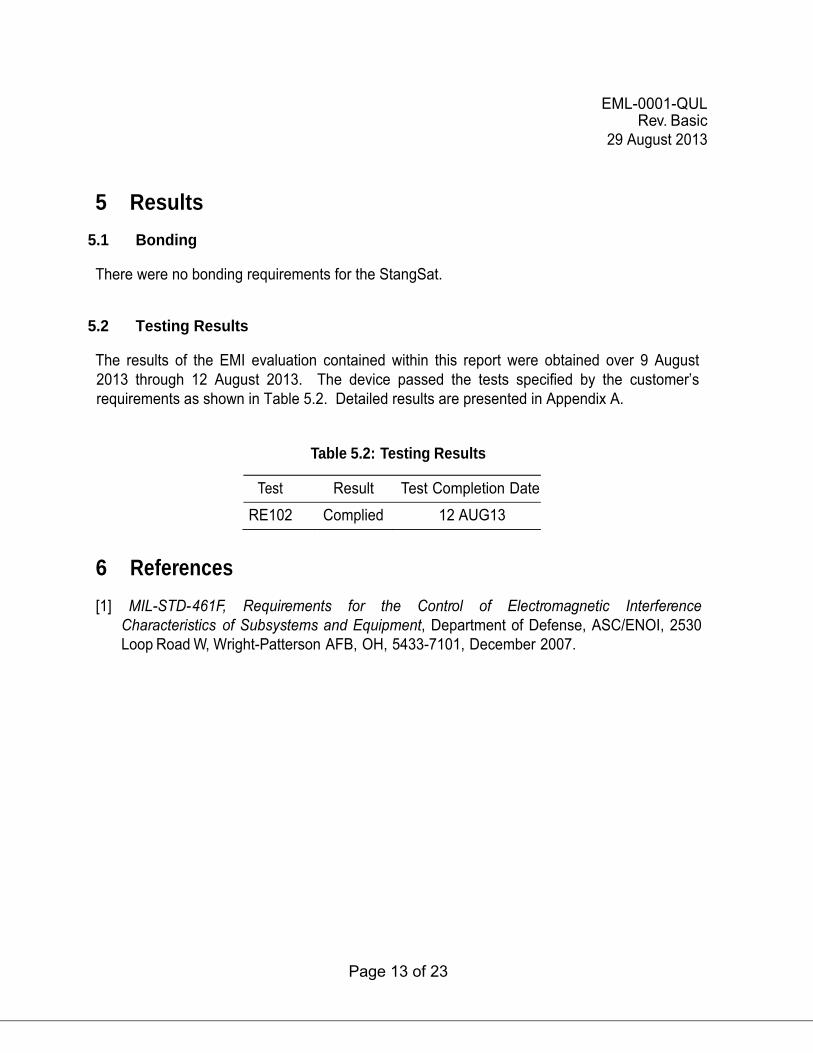
5 Results 5.1 Bonding There were no bonding requirements for the StangSat.
5.2 Testing Results The results of the EMI evaluation contained within this report were obtained over 9 August 2013 through 12 August 2013. The device passed the tests specified by the customer’s requirements as shown in Table 5.2. Detailed results are presented in Appendix A.
Table 5.2: Testing Results
Test Result Test Completion Date
RE102 Complied 12 AUG13
6 References [1] MIL-STD-461F, Requirements for the Control of Electromagnetic Interference
Characteristics of Subsystems and Equipment, Department of Defense, ASC/ENOI, 2530 Loop Road W, Wright-Patterson AFB, OH, 5433-7101, December 2007.
EML-0001-QUL Rev. Basic
29 August 2013
Page 14 of 23
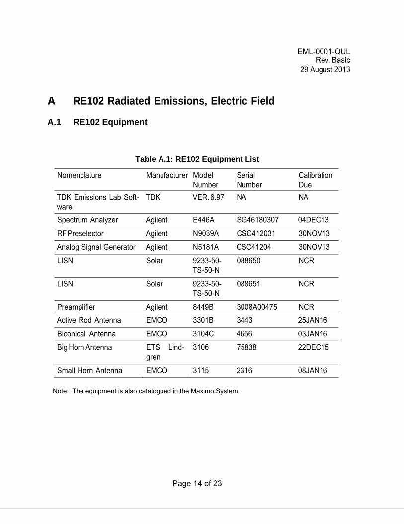
A RE102 Radiated Emissions, Electric Field A.1 RE102 Equipment
Table A.1: RE102 Equipment List
Nomenclature Manufacturer Model Number
Serial Number
Calibration Due
TDK Emissions Lab Soft- ware
TDK VER. 6.97 NA NA
Spectrum Analyzer Agilent E446A SG46180307 04DEC13
RF Preselector Agilent N9039A CSC412031 30NOV13
Analog Signal Generator Agilent N5181A CSC41204 30NOV13
LISN Solar 9233-50- TS-50-N
088650 NCR
LISN Solar 9233-50- TS-50-N
088651 NCR
Preamplifier Agilent 8449B 3008A00475 NCR
Active Rod Antenna EMCO 3301B 3443 25JAN16
Biconical Antenna EMCO 3104C 4656 03JAN16
Big Horn Antenna ETS Lind- gren
3106 75838 22DEC15
Small Horn Antenna EMCO 3115 2316 08JAN16
Note: The equipment is also catalogued in the Maximo System.

EML-0001-QUL Rev. Basic
29 August 2013
Page 15 of 23
A.2 Bandwidths and Dwell Times
Table A.2: RE102 Bandwidths and Dwell Times
Frequency Range Bandwidth Used Dwell Time Used
2 MHz to 30 MHz 10 kHz 15 milliseconds
30 MHz to 1 GHz 100 kHz 15 milliseconds
1 GHz to 18 GHz 1 MHz 15 milliseconds
EML-0001-QUL Rev. Basic
29 August 2013
Page 16 of 23
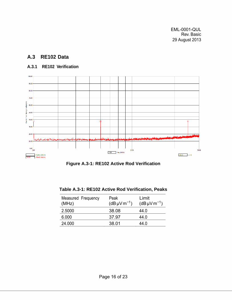
A.3 RE102 Data
A.3.1 RE102 Verification
Figure A.3-1: RE102 Active Rod Verification
Table A.3-1: RE102 Active Rod Verification, Peaks
Measured Frequency Peak Limit (MHz) (dB µV m−1) (dB µV m−1)
2.5000 38.08 44.0
6.000 37.97 44.0
24.000 38.01 44.0
EML-0001-QUL Rev. Basic
29 August 2013
Page 17 of 23
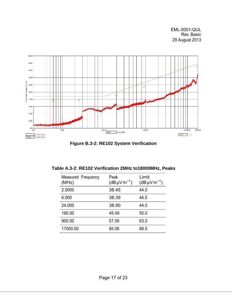
Figure B.3-2: RE102 System Verification
Table A.3-2: RE102 Verification 2MHz to18000MHz, Peaks
Measured Frequency Peak Limit (MHz) (dB µV m−1) (dB µV m−1)
2.5000 38.45 44.0
6.000 38.39 44.0
24.000 38.90 44.0
195.00 45.49 50.0
900.00 57.56 63.0
17000.00 85.06 88.5
EML-0001-QUL Rev. Basic
29 August 2013
Page 18 of 23
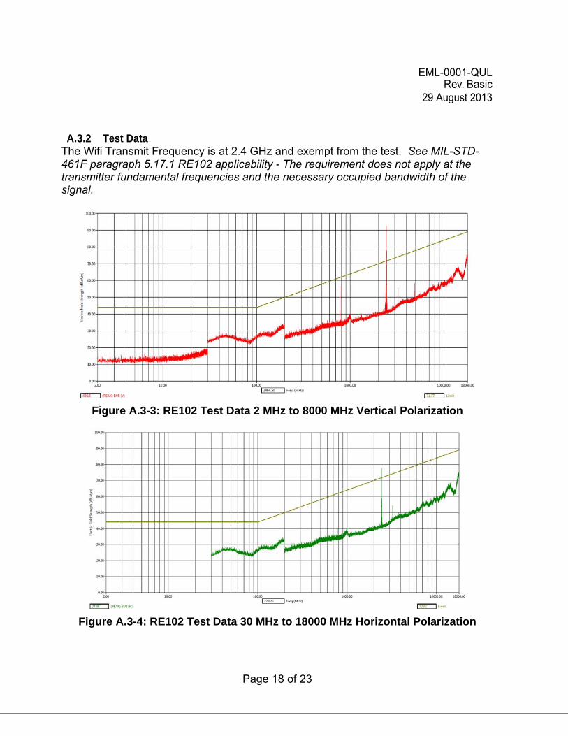
A.3.2 Test Data The Wifi Transmit Frequency is at 2.4 GHz and exempt from the test. See MIL-STD-461F paragraph 5.17.1 RE102 applicability - The requirement does not apply at the transmitter fundamental frequencies and the necessary occupied bandwidth of the signal.
Figure A.3-3: RE102 Test Data 2 MHz to 8000 MHz Vertical Polarization
Figure A.3-4: RE102 Test Data 30 MHz to 18000 MHz Horizontal Polarization
EML-0001-QUL Rev. Basic
29 August 2013
Page 19 of 23
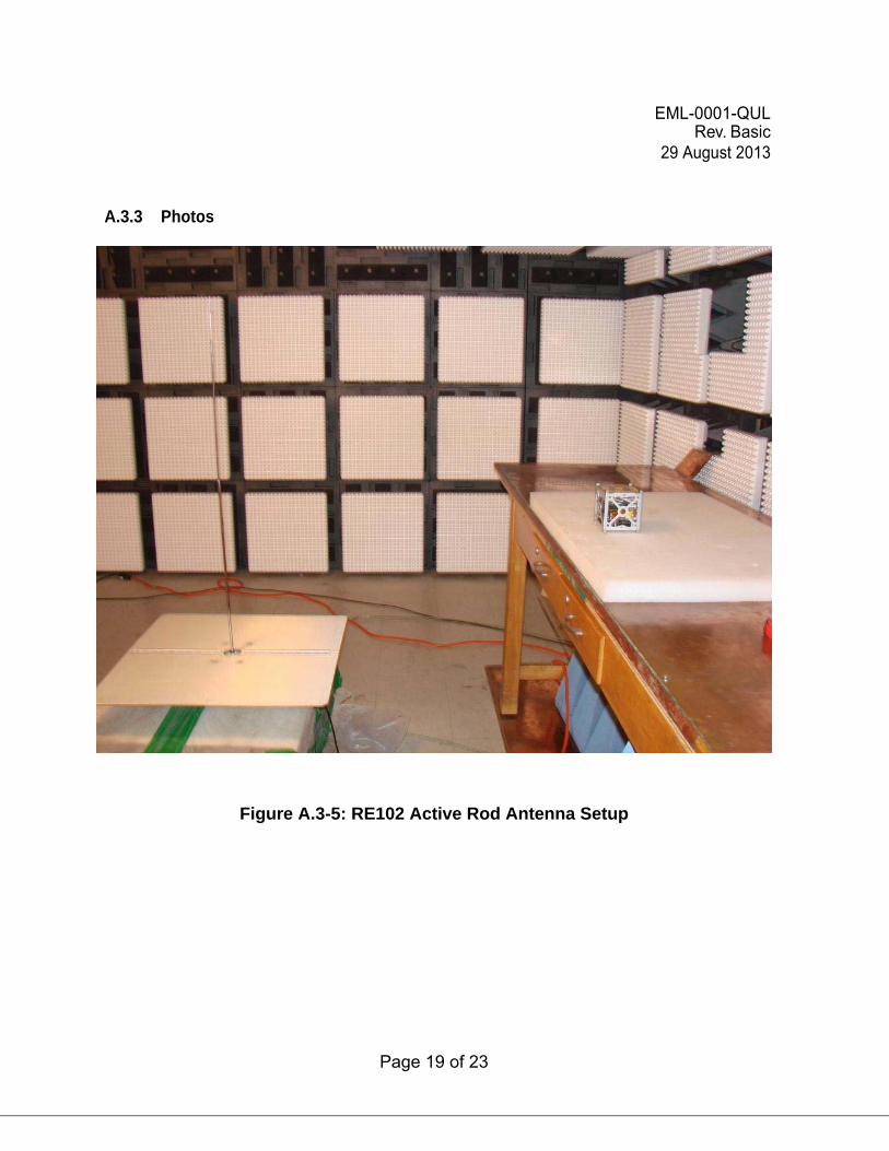
A.3.3 Photos
Figure A.3-5: RE102 Active Rod Antenna Setup
EML-0001-QUL Rev. Basic
29 August 2013
Page 20 of 23
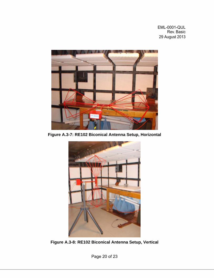
Figure A.3-7: RE102 Biconical Antenna Setup, Horizontal
Figure A.3-8: RE102 Biconical Antenna Setup, Vertical
EML-0001-QUL Rev. Basic
29 August 2013
Page 21 of 23
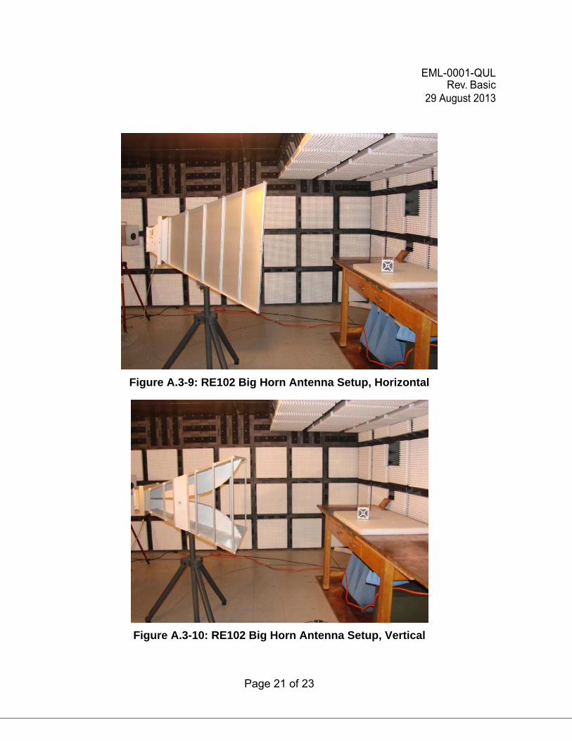
Figure A.3-9: RE102 Big Horn Antenna Setup, Horizontal
Figure A.3-10: RE102 Big Horn Antenna Setup, Vertical
EML-0001-QUL Rev. Basic
29 August 2013
Page 22 of 23
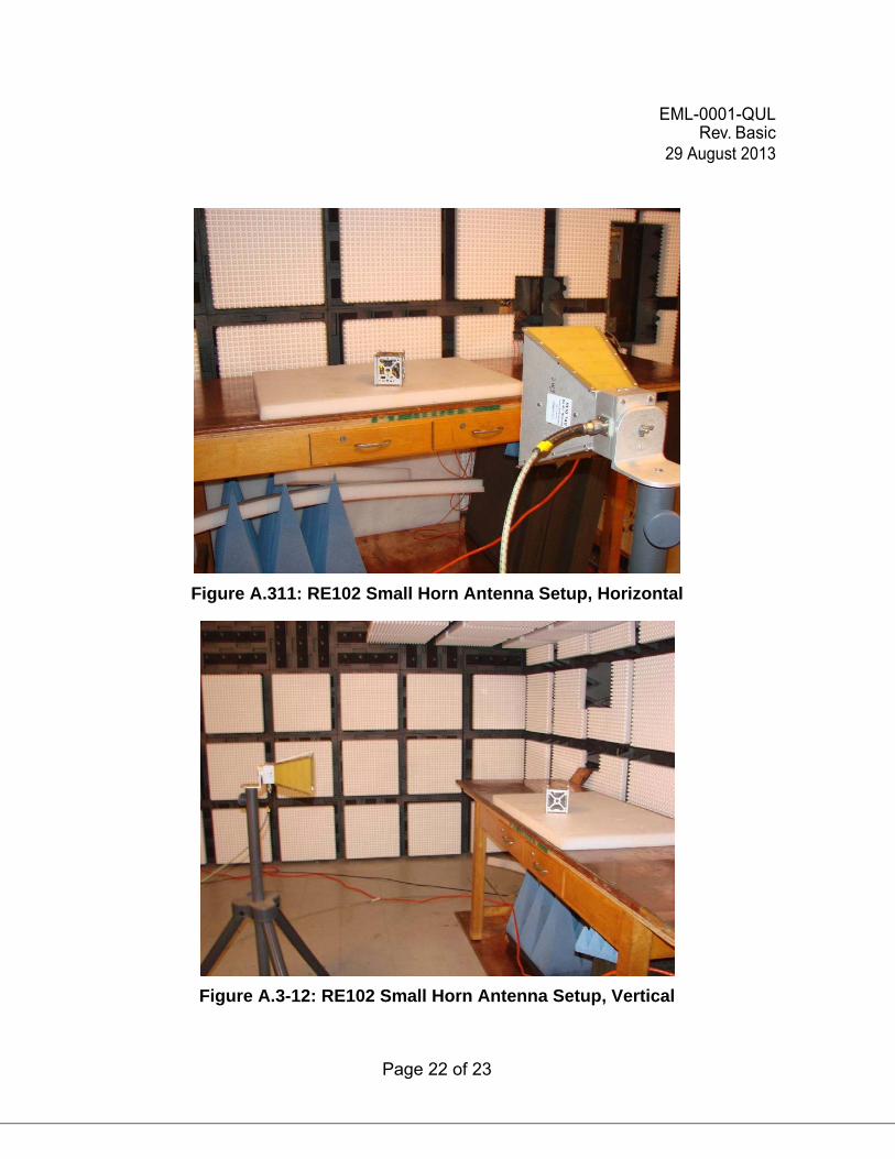
Figure A.311: RE102 Small Horn Antenna Setup, Horizontal
Figure A.3-12: RE102 Small Horn Antenna Setup, Vertical
EML-0001-QUL Rev. Basic
29 August 2013
Page 23 of 23
Electronic:
Shaun Daly [email protected] Peter S. Aragona [email protected] Lynne Carmody [email protected] Electromagnetics Laboratory EML document server