EMC TEST REPORT - TDK-Lambda. radio frequency immunity: iec 61000-4-3: 2006 ... emc test report 2011...
87
Nemko USA, Inc. 11696 Sorrento Valley Rd., Suite F San Diego, CA 92121-1024 Phone (858) 755-5525 Fax (858) 452-1810 EMC TEST REPORT For The Power supply for building-in Models: CPFE1000F-28 Prepared for: TDK-Lambda Americas Inc. 3055 Del Sol Blvd San Diego, CA 92154 Testing performed per the following: EMC Directive 2004/108/EC PREPARED on June 06, 2011 REPORT NUMBER: 2011 06175707-2 EMC PROJECT NUMBER: 1027254 NEX NUMBER: 175707
Transcript of EMC TEST REPORT - TDK-Lambda. radio frequency immunity: iec 61000-4-3: 2006 ... emc test report 2011...

Nemko USA, Inc. 11696 Sorrento Valley Rd., Suite F
San Diego, CA 92121-1024 Phone (858) 755-5525 Fax (858) 452-1810
EMC TEST REPORT
For The Power supply for building-in
Models:
CPFE1000F-28
Prepared for:
TDK-Lambda Americas Inc. 3055 Del Sol Blvd
San Diego, CA 92154
Testing performed per the following:
EMC Directive
2004/108/EC
PREPARED on June 06, 2011
REPORT NUMBER: 2011 06175707-2 EMC
PROJECT NUMBER: 1027254
NEX NUMBER: 175707

Nemko USA, Inc. 11696 Sorrento Valley Road, Suite F, San Diego, CA 92121 Phone (858) 755-5525 - Fax (858) 452-1810
DATE DOCUMENT NAME DOCUMENT # PAGE June 06, 2011 TDK-Lambda Americas Inc. - CPFE1000F-28 - EMC Test Report 2011 06175707-2 EMC ii of 87
TABLE OF CONTENTS
DOCUMENT HISTORY .................................................................................................................................. iv
CERTIFICATION .............................................................................................................................................. v
1. ADMINISTRATIVE DATA AND TEST SUMMARY .......................................................................... 6 1.1. ADMINISTRATIVE DATA ............................................................................................................................ 6 1.2. REFERENCED STANDARDS FOR RADIATED EMISSIONS ............................................................................... 7 1.3. REFERENCED STANDARDS FOR ELECTROMAGNETIC COMPATIBILITY ........................................................ 7 1.4. TEST SUMMARY ......................................................................................................................................... 8
2. SYSTEM CONFIGURATION ............................................................................................................... 10 2.1. SYSTEM COMPONENTS AND POWER CABLES ........................................................................................... 10 2.2. DEVICE INTERCONNECTION AND I/O CABLES .......................................................................................... 10 2.3. DESCRIPTION AND METHOD OF EXERCISING THE EUT ............................................................................ 10 2.4. DESIGN MODIFICATIONS FOR COMPLIANCE ............................................................................................. 10
3. DESCRIPTION OF TEST SITE AND EQUIPMENT ......................................................................... 12 3.1. DESCRIPTION OF TEST SITE ..................................................................................................................... 12 3.2. FACILITY ACCREDITATION AND AUTHORIZATION ................................................................................... 12
4. DESCRIPTION OF TESTING METHODS ......................................................................................... 12 4.1. INTRODUCTION ........................................................................................................................................ 12 4.2. TEST METHODS ....................................................................................................................................... 12 4.3. CONFIGURATION AND METHODS OF MEASUREMENTS FOR CONDUCTED EMISSIONS ............................... 14 4.4. CONFIGURATION AND METHODS OF MEASUREMENTS FOR FREQUENCY IDENTIFICATION ....................... 15 4.5. CONFIGURATION AND METHODS OF MEASUREMENTS FOR RADIATED EMISSIONS ................................... 17 4.6. POWER LINE HARMONICS: EN 61000-3-2: 2006 ..................................................................................... 19 4.7. POWER LINE FLUCTUATIONS/FLICKER: EN 61000-3-3: 2008 .................................................................. 19 4.8. DEVICE PERFORMANCE CRITERIA FOR IMMUNITY TESTS ........................................................................ 21 4.9. ELECTROSTATIC DISCHARGE IMMUNITY: IEC 61000-4-2: 2008 .............................................................. 22 4.10. RADIO FREQUENCY IMMUNITY: IEC 61000-4-3: 2006 ........................................................................ 24 4.11. ELECTRICAL FAST TRANSIENT IMMUNITY: IEC 61000-4-4: 2004 ....................................................... 26 4.12. POWER LINE SURGE IMMUNITY: IEC 61000-4-5: 2005 ....................................................................... 28 4.13. RADIO FREQUENCY CONDUCTED COMMON MODE IMMUNITY: IEC 61000-4-6: 2008 ......................... 30 4.14. POWER FREQUENCY MAGNETIC FIELD IMMUNITY: IEC 61000-4-8: 2009 ........................................... 32 4.15. VOLTAGE DIPS AND SHORT INTERRUPTIONS: IEC 61000-4-11: 2004 .................................................. 34 4.16. OSCILLATORY WAVES IMMUNITY: IEC 61000-4-12: 2006 .................................................................. 36 4.17. VOLTAGE FLUCTUATION IMMUNITY: IEC 61000-4-14:1999 + A1:2004 ............................................. 38
5. CE-MARK TEST RESULTS ................................................................................................................. 40 5.1. CONDUCTED EMISSIONS TEST DATA ....................................................................................................... 40 5.2. RADIATED EMISSIONS TEST DATA........................................................................................................... 43 5.3. POWER LINE HARMONICS TEST RESULTS ................................................................................................ 45 5.4. ELECTROSTATIC DISCHARGE IMMUNITY TEST RESULTS & TEST POINTS ................................................ 50 5.5. RADIO FREQUENCY IMMUNITY TEST RESULTS ........................................................................................ 53 5.6. ELECTRICAL FAST TRANSIENT BURST IMMUNITY TEST RESULTS ............................................................ 55 5.7. POWER LINE SURGE IMMUNITY TEST RESULTS ....................................................................................... 56 5.8. RF CONDUCTED COMMON MODE DISTURBANCE IMMUNITY TEST RESULTS ........................................... 57 5.9. POWER FREQUENCY MAGNETIC FIELD IMMUNITY .................................................................................. 58 5.10. VOLTAGE DIPS AND INTERRUPTIONS IMMUNITY TEST RESULTS.......................................................... 59

Nemko USA, Inc. 11696 Sorrento Valley Road, Suite F, San Diego, CA 92121 Phone (858) 755-5525 - Fax (858) 452-1810
DATE DOCUMENT NAME DOCUMENT # PAGE June 06, 2011 TDK-Lambda Americas Inc. - CPFE1000F-28 - EMC Test Report 2011 06175707-2 EMC iii of 87
5.11. OSCILLATORY WAVES IMMUNITY TEST RESULTS ............................................................................... 60 5.12. VOLTAGE FLUCTUATION IMMUNITY TEST RESULTS ............................................................................ 61
TEST SETUP DIAGRAMS FIGURE 1. CONDUCTED EMISSIONS TEST SETUP DIAGRAM ................................................................................. 14 FIGURE 2. FREQUENCY ID OF RADIATED EMISSIONS TEST SETUP DIAGRAM ..................................................... 16 FIGURE 3. RADIATED EMISSIONS TEST SETUP DIAGRAM ................................................................................... 18 FIGURE 4. HARMONICS & FLICKER TEST SETUP DIAGRAM ................................................................................ 20 FIGURE 5. ESD TEST SETUP DIAGRAM .............................................................................................................. 23 FIGURE 6. RADIO FREQUENCY IMMUNITY TEST SETUP DIAGRAM ..................................................................... 25 FIGURE 7. EFT IMMUNITY TEST SETUP DIAGRAM ............................................................................................. 27 FIGURE 8. POWER LINE SURGE IMMUNITY TEST SETUP DIAGRAM ..................................................................... 29 FIGURE 9. RF COMMON MODE IMMUNITY TEST SETUP DIAGRAM ..................................................................... 31 FIGURE 10. POWER FREQUENCY MAGNETIC FIELD IMMUNITY TEST SETUP ....................................................... 33 FIGURE 11. VOLTAGE DIPS AND SHORT INTERRUPTIONS TEST SETUP DIAGRAM ................................................ 35 FIGURE 12. OSCILLATORY WAVES IMMUNITY TEST SETUP DIAGRAM ................................................................ 37 FIGURE 13. VOLTAGE FLUCTUATION IMMUNITY TEST SETUP DIAGRAM ............................................................ 39 FIGURE 14. ESD TEST POINTS ............................................................................................................................ 51 FIGURE 15. ESD TEST POINTS ............................................................................................................................ 52
TEST CONFIGURATION PHOTOGRAPHS PHOTOGRAPH 1. EUT FRONT AND REAR OF 28VDC OUTPUT MODEL ................................................................. 11 PHOTOGRAPH 2. GENERAL EUT TEST CONFIGURATION OF 28VDC OUTPUT MODEL .......................................... 13 PHOTOGRAPH 3. CONDUCTED EMISSIONS TEST CONFIGURATION ....................................................................... 62 PHOTOGRAPH 4. RADIATED EMISSIONS TEST CONFIGURATION .......................................................................... 63 PHOTOGRAPH 5. HARMONICS & FLICKER TEST CONFIGURATION ....................................................................... 64 PHOTOGRAPH 6. ESD TEST CONFIGURATION ..................................................................................................... 65 PHOTOGRAPH 7. RADIO FREQUENCY IMMUNITY TEST CONFIGURATION ............................................................ 66 PHOTOGRAPH 8. EFT IMMUNITY TEST CONFIGURATION .................................................................................... 67 PHOTOGRAPH 9. POWER LINE SURGE IMMUNITY TEST CONFIGURATION ............................................................ 68 PHOTOGRAPH 10. RF CONDUCTED IMMUNITY TEST CONFIGURATION ................................................................ 69 PHOTOGRAPH 11. POWER FREQUENCY MAGNETIC FIELD IMMUNITY TEST CONFIGURATION ............................. 70 PHOTOGRAPH 12. VOLTAGE DIPS AND INTERRUPTIONS IMMUNITY TEST CONFIGURATION ................................ 71 PHOTOGRAPH 13. OSCILLATORY WAVES IMMUNITY TEST CONFIGURATION ...................................................... 72 PHOTOGRAPH 14. VOLTAGE FLUCTUATION IMMUNITY TEST CONFIGURATION .................................................. 73
APPENDICES A. RADIATED EMISSIONS MEASUREMENT UNCERTAINTIES ................................................................................ A1 B. NEMKO USA, INC. TEST EQUIPMENT & FACILITIES CALIBRATION PROGRAM ............................................... B1 C. NVLAP ACCREDITATION .............................................................................................................................. C1 D. CE102 PER MIL-STD-461E ………………………………………………………………… …………….D1
Nemko USA, Inc. 11696 Sorrento Valley Road, Suite F, San Diego, CA 92121 Phone (858) 755-5525 - Fax (858) 452-1810
DATE DOCUMENT NAME DOCUMENT # PAGE June 06, 2011 TDK-Lambda Americas Inc. - CPFE1000F-28 - EMC Test Report 2011 06175707-2 EMC iv of 87
DOCUMENT HISTORY
REVISION DATE COMMENTS
- June 06, 2011 Prepared By: Alex Chang
- June 06, 2011 Initial Release: Alan Laudani NOTE: Nemko USA, Inc. hereby makes the following statements so as to conform to the Subclause 5.10 Requirements of ISO/IEC 17025 "General Criteria For the Competence Of Testing and Calibration Laboratories":
o The unit described in this report was received at Nemko USA, Inc.'s facilities on May 13, 2011.
o Testing was performed on the unit described in this report on May 13, 2011 to May #, 2011.
o The Test Results reported herein apply only to the Unit actually tested, and to substantially identical Units.
o This report does not imply the endorsement of the Federal Communications Commission (FCC), NVLAP or any other government agency.
This Report is the property of Nemko USA, Inc., and shall not be reproduced, except in full, without prior written approval of Nemko USA, Inc. However, all ownership rights are hereby returned unconditionally to TDK-Lambda Americas Inc., and approval is hereby granted to TDK-Lambda Americas Inc. and its employees and agents to reproduce all or part of this report for any legitimate business purpose without further reference to Nemko USA, Inc.

Nemko USA, Inc. 11696 Sorrento Valley Road, Suite F, San Diego, CA 92121 Phone (858) 755-5525 - Fax (858) 452-1810
DATE DOCUMENT NAME DOCUMENT # PAGE June 06, 2011 TDK-Lambda Americas Inc. - CPFE1000F-28 - EMC Test Report 2011 06175707-2 EMC v of 87
CERTIFICATION
The compatibility testing and this report have been prepared by Nemko USA, Inc., an independent
electromagnetic compatibility consulting and test laboratory.
Testing and data collection were accomplished in accordance with the test methods listed in this report.
I certify the data evaluation and equipment configuration herein to be a true and accurate representation of the
sample's test characteristics, as of the test date(s), and for the design of the test sample utilized to compile this
report.
Alan Laudani, EMC/RF TEST ENGINEER

Nemko USA, Inc. 11696 Sorrento Valley Road, Suite F, San Diego, CA 92121 Phone (858) 755-5525 - Fax (858) 452-1810
DATE DOCUMENT NAME DOCUMENT # PAGE June 06, 2011 TDK-Lambda Americas Inc. - CPFE1000F-28 - EMC Test Report 2011 06175707-2 EMC 6 of 87
1. ADMINISTRATIVE DATA AND TEST SUMMARY 1.1. Administrative Data
CLINET: TDK-Lambda Americas Inc. 3055 Del Sol Blvd San Diego, CA 92154 (619) 628-2844
CONTACT: Phong Ly E-MAIL: [email protected] DATES OF TESTING: May 13, 2011 to June 03, 2011 EQUIPMENT UNDER TEST (EUT): Power supply for building-in MODEL: CPFE1000F-28 SERIAL NUMBER: CLW-132S17-0008 S490 HIGHEST FREQUENCY GENERATED OR USED: 200 KHZ CONDITION UPON RECEIPT: Suitable for Test TEST SPECIFICATIONS: Radio Frequency Emissions in accordance with
requirements of EN 55022: 2006/A1: 2007.
Electromagnetic Immunity tests in accordance with requirements of EN 55024: 1998/A1: 2001/A2: 2003/IS1: 2007

Nemko USA, Inc. 11696 Sorrento Valley Road, Suite F, San Diego, CA 92121 Phone (858) 755-5525 - Fax (858) 452-1810
DATE DOCUMENT NAME DOCUMENT # PAGE June 06, 2011 TDK-Lambda Americas Inc. - CPFE1000F-28 - EMC Test Report 2011 06175707-2 EMC 7 of 87 1.2. Referenced Standards for Radiated Emissions
Test Type In Accordance with Document Document Title
Conducted and Radiated Emissions
EN 55022: 2006/A1: 2007
Information technology equipment—Radio disturbance characteristics —Limits and methods of measurement
1.3. Referenced Standards for Electromagnetic Compatibility
Test Type In Accordance with Document
Document Title
Power Line Harmonics EN 61000-3-2: 2006 Electromagnetic Compatibility, Limits for Harmonic Current Emissions, Equipment Input Current < 16A
Power Line Flicker EN 61000-3-3: 2008 Electromagnetic Compatibility, Limitation of Voltage Fluctuations and Flicker In Low-Voltage Supply Systems for Equipment with Rated Current < 16A
Electrostatic Discharge Immunity IEC 61000-4-2: 2008
Electromagnetic Compatibility—Testing and measurement techniques - Electrostatic discharge immunity test
Radio Frequency Immunity IEC 61000-4-3: 2006
Electromagnetic Compatibility—Testing and measurement techniques - Radiated radio frequency electromagnetic field immunity test
Electrical Fast Transient Burst Immunity
IEC 61000-4-4: 2004 Electromagnetic Compatibility—Testing and measurement techniques - Electrical fast transient / burst immunity
Power Line Surge Immunity IEC 61000-4-5: 2005 Electromagnetic Compatibility—Testing and
measurement techniques - Surge immunity test
RF Common Mode Immunity IEC 61000-4-6: 2008
Electromagnetic Compatibility—Testing and measurement techniques - Immunity to conducted disturbances, induced by radio-frequency fields
Power Frequency Magnetic Field IEC 61000-4-8: 2009
Electromagnetic Compatibility—Testing and measurement techniques - for Power Frequency Magnetic Field, Immunity Test
Voltage Dips and Short Interruptions Immunity IEC 61000-4-11: 2004
Electromagnetic Compatibility—Testing and measurement techniques - Voltage dips, short interruptions and voltage variations immunity tests
Ring wave immunity test IEC 61000-4-12: 2006 Electromagnetic Compatibility—Testing and
measurement techniques - Ring wave immunity test
Voltage fluctuation immunity test
IEC 61000-4-14: 1999 + A1:2004
Electromagnetic Compatibility—Testing and measurement techniques - Voltage fluctuation immunity test

Nemko USA, Inc. 11696 Sorrento Valley Road, Suite F, San Diego, CA 92121 Phone (858) 755-5525 - Fax (858) 452-1810
DATE DOCUMENT NAME DOCUMENT # PAGE June 06, 2011 TDK-Lambda Americas Inc. - CPFE1000F-28 - EMC Test Report 2011 06175707-2 EMC 8 of 87 1.4. Test Summary 1.4.1. Emissions Test Summary The Compliance Status is a judgment based on the calculated highest emissions to appropriate standard limits. Measurement uncertainty values, provided on calibration certificates, were not be used in the judgment of the final status of compliance.
Test Methods Frequency Range Compliance Status EN 55022: 2006/A1: 2007, Class “B” Conducted Emissions 0.15 MHz – 30 MHz PASS
EN 55022: 2006/A1: 2007, Class “B” Telecom Conducted Emissions 0.15 MHz – 30 MHz No telecom ports.
Not applicable EN 55022: 2006/A1: 2007, Class “B” Radiated Emissions 30 MHz – 1000 MHz PASS
EN 61000-3-2: 2006 Power Line Harmonics up to the 40th Harmonic PASS
EN 61000-3-3: 2008 Power Line Flicker
less than or equal to 4% Maximum Relative Voltage Change; Value of D(T) less than or equal to 3% for more than 200
ms
PASS
Alan Laudani, EMC/RF Test Engineer.

Nemko USA, Inc. 11696 Sorrento Valley Road, Suite F, San Diego, CA 92121 Phone (858) 755-5525 - Fax (858) 452-1810
DATE DOCUMENT NAME DOCUMENT # PAGE June 06, 2011 TDK-Lambda Americas Inc. - CPFE1000F-28 - EMC Test Report 2011 06175707-2 EMC 9 of 87
1.4.2. Immunity Test Summary
Test Methods
Minimum Criterion
Level Required as per EN 55024
Criterion Level Tested
as per customer requested
Compliance Status
IEC 61000-4-2: 2008 - ESD Immunity
Criterion B± 8 kV Air discharge,
± 4 kV Contact discharge
Criterion B ± 8 kV Air Discharge,
± 4 kV Contact Discharge PASS
IEC 61000-4-3: 2006 -Radio Frequency Immunity
Criterion A3 V/m from 80-1000 MHz
(80% AM at 1kHz)
Criterion A 10 V/m from 80-1000 MHz
(80% AM at 1kHz) PASS
IEC 61000-4-4: 2004 -Electrical Fast Transient Immunity
Criterion BPower Line Pulses of ± 1 kV; I/O Line Pulses of ± 0.5 kV
Criterion B Power Line Pulses of ± 2 kV;
I/O Line Pulses of ± 1 kV PASS
IEC 61000-4-5: 2005 -Surge Immunity
Criterion B± 2kV Common mode surges,
± 1kV Differential mode surges
Criterion B ± 4 kV Common Mode Surges,
± 2 kV Differential Mode Surges PASS
IEC 61000-4-6: 2008 -RF Common Mode Immunity
Criterion A 150 kHz - 80 MHz at 3 Vrms
1 kHz 80% amplitude modulated
Criterion B 150 kHz - 80 MHz at 10 Vrms
1kHz 80% amplitude modulated PASS*
IEC 61000-4-8: 2009 Power Frequency Magnetic Field
Criterion A Inductive loop at 50 Hz,
to 1.0 amps (rms) per meter
Criterion A Inductive loop at 50 Hz,
to 30 amps (rms) per meter PASS
IEC 61000-4-11: 2004 - Voltage Dips and Short Interruptions
Criterion B and C Voltage Dips of 30% and >95%;
Interruptions of >95%.
Criterion B and C Voltage Dips of 60%, 30%, 20%
and >95%; Interruptions of >95%. PASS
MIL STD 461/462D CE102.
PASS
IEC 61000-4-12: 2006 - Oscillatory waves immunity
N/A Criterion A
± 2kV common mode ring ± 1kV differential mode ring
PASS
IEC 61000-4-14: 1999 + A1:2004 - Voltage fluctuation immunity
N/A
Criterion A ΔU = ± 12% Un ΔU = + 12% Un ΔU = - 12% Un
PASS
* Customer upon agreed to lower the criteria, which the EUT is self-recoverable during the test. Refer to result section for detail information. REFER TO THE TEST RESULTS SECTION FOR FURTHER DETAILS.
Alan Laudani, EMC/RF Test Engineer

Nemko USA, Inc. 11696 Sorrento Valley Road, Suite F, San Diego, CA 92121 Phone (858) 755-5525 - Fax (858) 452-1810
DATE DOCUMENT NAME DOCUMENT # PAGE June 06, 2011 TDK-Lambda Americas Inc. - CPFE1000F-28 - EMC Test Report 2011 06175707-2 EMC 10 of 87
2. SYSTEM CONFIGURATION 2.1. System Components and Power Cables
DEVICE
MANUFACTURER MODEL # SERIAL #
POWER CABLE
EUT - Power supply for building-in with 28VDC output
TDK-Lambda Americas Inc. CPFE1000F-28 CLW-132S17-0008 S490
1m, unshielded, 16AWG, 3-wire, IEC connector
Support – Heat sink N/A None
Support – 0.8Ω resistor load for 28VDC output model
Custom made None
2.2. Device Interconnection and I/O Cables Connection I/O Cable
EUT to resistor loads < 1m, unshielded, 8AWG cables
2.3. Description and Method of Exercising the EUT The CPFE1000F-28 is a Power supply for building-in. Their function is to supply 28VDC output, respectively. The EUT was exercised with resistors load 0.8 Ω on the output connections. The load is considered as maximum condition. The EUT has been monitored DC voltages by a multimeter; if the DC voltage is disrupted as seen/indicated by meter ±56mV, or there is loss of functionality, this may be considered a failure.
2.4. Design Modifications for Compliance
Device: Power supply for building-in Model: CPFE1000F-28 The following design modifications were made to the EUT during testing. None. No design modifications were made to the EUT during testing.

Nemko USA, Inc. 11696 Sorrento Valley Road, Suite F, San Diego, CA 92121 Phone (858) 755-5525 - Fax (858) 452-1810
DATE DOCUMENT NAME DOCUMENT # PAGE June 06, 2011 TDK-Lambda Americas Inc. - CPFE1000F-28 - EMC Test Report 2011 06175707-2 EMC 11 of 87
Photograph 1. EUT Front and Rear of 28VDC output model
EUT Front
EUT Rear

Nemko USA, Inc. 11696 Sorrento Valley Road, Suite F, San Diego, CA 92121 Phone (858) 755-5525 - Fax (858) 452-1810
DATE DOCUMENT NAME DOCUMENT # PAGE June 06, 2011 TDK-Lambda Americas Inc. - CPFE1000F-28 - EMC Test Report 2011 06175707-2 EMC 12 of 87
3. DESCRIPTION OF TEST SITE AND EQUIPMENT
3.1. Description of Test Site The test site is located at 11696 Sorrento Valley Road, Suite F, San Diego, CA 92121. The site is physically located 18 miles Northwest of downtown San Diego. The general area is a valley 1.5 miles east of the Pacific Ocean. This particular part of the valley tends to minimize ambient levels, i.e. radio and TV broadcast stations and land mobile communications. The three and ten-meter Open Area Test Site (OATS) is located behind the office/lab building. It conforms to the normalized site attenuation limits and construction specifications as set in the EN 55022: 2006/A1: 2007, CISPR 16: 2003 and ANSI C63.4: 2009 documents.
3.2. Facility Accreditation and Authorization Registrations of the facility sites are on file with:
Organization Registration numbers Federal Communications Commission 0013750831 VCCI R-3027 (Radiated) and C-3352 (Conducted) Industry Canada 2040B-1 and 2040B-2
4. DESCRIPTION OF TESTING METHODS
4.1. Introduction Nemko USA, Inc. is accredited to ISO/IEC 17025 by the National Voluntary Laboratory Accreditation Program (NVLAP) for Electromagnetic Compatibility and Telecommunications testing. Part of the accreditation process involves the demonstration of competence in various test methods. Prior to the beginning of work, Nemko personnel work with their clients to ensure the proper test standards and test methods are utilized. Applicable tests and the minimum criteria for a pass condition are listed in the administrative section of this report.
4.2. Test Methods The harmonized documents published for Information Technology Equipment are EN 55022: 2006/A1: 2007 for radio frequency emissions and EN 55024: 1998/A1: 2001/A2: 2003/IS1: 2007 for electromagnetic immunity. The methods employed to test the emissions and immunity characteristics of the Equipment Under Test are those mandated by the European Standards EN 55022 and EN 55024. The applicable tests and the minimum criteria for a pass condition that are listed in the administrative section of this report are taken from these standards. Digital devices sold in Canada are required to comply with the Interference Causing Equipment Standard for Digital Apparatus, ICES-003, Issue 4. These test methods and limits are specified in the Canadian Standards Association’s Standard CAN/CSA-CISPR 22-02 and are “essentially equivalent” with the CISPR 22 (EN55022) rules for unintentional radiators per EMCAB-3, Issue 4 (December 2005). No additional testing is required for compliance to ICES-003.

Nemko USA, Inc. 11696 Sorrento Valley Road, Suite F, San Diego, CA 92121 Phone (858) 755-5525 - Fax (858) 452-1810
DATE DOCUMENT NAME DOCUMENT # PAGE June 06, 2011 TDK-Lambda Americas Inc. - CPFE1000F-28 - EMC Test Report 2011 06175707-2 EMC 13 of 87
Photograph 2. General EUT Test Configuration of 28VDC output model

Nemko USA, Inc. 11696 Sorrento Valley Road, Suite F, San Diego, CA 92121 Phone (858) 755-5525 - Fax (858) 452-1810
DATE DOCUMENT NAME DOCUMENT # PAGE June 06, 2011 TDK-Lambda Americas Inc. - CPFE1000F-28 - EMC Test Report 2011 06175707-2 EMC 14 of 87
4.3. Configuration and Methods of Measurements for Conducted Emissions This test measures the levels emanating from the EUT, thus evaluating the potential for the EUT to cause radio frequency interference to other electronic devices. Testing was performed in accordance with the test standard(s) referenced in the test summary section of this report. The Equipment Under Test (EUT) was configured based upon the requirements of the applicable test standard.
Figure 1. Conducted Emissions Test Setup Diagram
NOT TO SCALE CONFIGURATION LEGEND
1. Test Laboratory (6 X 6 meters) 2. Ground Plane (15 square meters) 3. Vertical Conducting Wall (Grounded through Ground Plane via 10' ground rod) 4. AC Power for Devices 5. Power Line Filter, Lindgren, 120 dB, 30 amp 6. Artificial Mains Network (AMN) for peripheral devices 7. Power Distribution Box for peripheral devices 8. Spectrum Analyzer with Quasi-Peak Adapter 9. High Pass Filter 10. Coax input from EUT AMN to Spectrum Analyzer 11. AMN for EUT 12. Non-conducting table 13. EUT and Associated System
8
7
40 cm
9
4 1
2
3 6 5
11
12
13
10

Nemko USA, Inc. 11696 Sorrento Valley Road, Suite F, San Diego, CA 92121 Phone (858) 755-5525 - Fax (858) 452-1810
DATE DOCUMENT NAME DOCUMENT # PAGE June 06, 2011 TDK-Lambda Americas Inc. - CPFE1000F-28 - EMC Test Report 2011 06175707-2 EMC 15 of 87 4.4. Configuration and Methods of Measurements for Frequency Identification When performing all testing of equipment, the actual emissions of the EUT are segregated from ambient signals present within the laboratory or the open-field test range. Preliminary testing is performed to ensure that ambient signals are sufficiently low to allow for proper observation of the emissions from the EUT. Incoming power lines are filtered using a 120 dB, 30-ampere; 115/208-volt filter to assist in reducing ambient signals for tests of levels of conducted emissions. Ambients within the laboratory are compared to those noted at the nearby open-field site to discriminate between signals produced from the EUT and ambient signals. In the event that a significant emission is produced by the EUT at a frequency which is also demonstrating significant ambient signals, the spectrum analyzer is placed in the peak mode, the bandwidth is narrowed, the EUT's signal is centered on the analyzer, the scan width is expanded to 50 kHz while monitoring the audio to ensure that only the EUT signal is present, the analyzer is switched to quasi-peak mode, and the level of the EUT signal is recorded. For Frequency ID Test Configuration please refer to the figure on the following page.

Nemko USA, Inc. 11696 Sorrento Valley Road, Suite F, San Diego, CA 92121 Phone (858) 755-5525 - Fax (858) 452-1810
DATE DOCUMENT NAME DOCUMENT # PAGE June 06, 2011 TDK-Lambda Americas Inc. - CPFE1000F-28 - EMC Test Report 2011 06175707-2 EMC 16 of 87
Figure 2. Frequency ID of Radiated Emissions Test Setup Diagram
NOT TO SCALE
CONFIGURATION LEGEND
1. Test Laboratory 2. Spectrum Analyzer with Quasi-Peak Adapter 3. Coax interconnect from Antenna to Spectrum Analyzer 4. Receive Antenna (basic relative position) 5. Non-Conducting table 80 cm above ground plane 6. Power strip for EUT and peripherals 7. AC power for devices 8. EUT: Power supply for building-in and Associated System
1
8
1m
2
3
4
5
6 7

Nemko USA, Inc. 11696 Sorrento Valley Road, Suite F, San Diego, CA 92121 Phone (858) 755-5525 - Fax (858) 452-1810
DATE DOCUMENT NAME DOCUMENT # PAGE June 06, 2011 TDK-Lambda Americas Inc. - CPFE1000F-28 - EMC Test Report 2011 06175707-2 EMC 17 of 87 4.5. Configuration and Methods of Measurements for Radiated Emissions This test measures the levels emanating from the EUT, thus evaluating the potential for the EUT to cause radio frequency interference to other electronic devices. Testing was performed in accordance with the test standard(s) referenced in the test summary section of this report. The Equipment Under Test (EUT) was configured based upon the requirements of the applicable test standard. Initially, the primary emission frequencies are identified inside a shielded chamber by positioning a broadband receive antenna one meter from the EUT. Next, the EUT and associated system are placed on a turntable on a ten-meter open area test site (OATS) with known attenuation characteristics and all significant radiated emissions are recorded. To ensure that the maximum emission at each discrete frequency of interest is observed, the receive antenna is varied in height from one to four meters and rotated to produce horizontal and vertical polarities while the turntable is rotated to determine the worst emitting configuration. The numerical results are included herein to demonstrate compliance. The numerical results of the test are included herein to demonstrate compliance. The numerical results that are applied to the emissions limits are arrived as demonstrated by the example below: A. Frequency Measured in MHz. B. Meter Reading: Emission Amplitude as measured with the antenna in Vertical polarity in dBμV, this is from the EMI receiver or Spectrum Analyzer. C. Meter Reading: Emission Amplitude as measured with the antenna in Horizontal polarity in dBμV, this is from the EMI receiver or Spectrum Analyzer. D. Detector used: Q for Quasi-Peak, A for average, P for peak. E. EUT Side F/L/R/B: Side of EUT facing the receiving antenna. Front, Left, Right, Back. If not noted, emission did not peak in a significant manner to discriminate which side of the EUT emitted the emission. F. Ant. Height m: Antenna height in meters of strongest emission measured when raised from 1 to 4 meters. G. Max Reading: Max meter reading of B vertical and C horizontal in dBμV. H. Corrected Reading: Corrected Reading in dBμV/m; Max Reading corrected for cable loss (dB), antenna factor (dBV/m) and preamplifier gain (dB). I. Spec limit: Specification Limit at the measured frequency in dBμV/m. J. CR/SL Diff.: Difference in dB of Corrected Reading and Specification Limit, negative results indicate a margin value below the specification limit. K. Pass Fail: Result; EUT does or does not comply at this frequency.
A B C D E F G H I J KMeas. Meter Meter Det. EUT Ant. Max. Corrected Spec. CR/SL PassFreq. Reading Reading Side Height Reading Reading limit Diff. Fail(MHz) Vertical Horizontal F/L/R/B m (dBμV) (dBμV/m) (dBμV/m) (dB)
47.2 44.5 44.6 Q - 1.0 44.6 24.2 30.0 -5.8 Pass

Nemko USA, Inc. 11696 Sorrento Valley Road, Suite F, San Diego, CA 92121 Phone (858) 755-5525 - Fax (858) 452-1810
DATE DOCUMENT NAME DOCUMENT # PAGE June 06, 2011 TDK-Lambda Americas Inc. - CPFE1000F-28 - EMC Test Report 2011 06175707-2 EMC 18 of 87
Figure 3. Radiated Emissions Test Setup Diagram
NOT TO SCALE
CONFIGURATION LEGEND 1. Ground plane (11 X 17 meters) 2. Spectrum Analyzer with Quasi-Peak Adapter 3. Coax interconnect from Receive Antenna to Spectrum Analyzer 4. Antenna Mast with motorized mounting assembly 5. Receive Antenna (basic relative position) 6. Non-Conducting table 80 cm above ground plane 7. Mains power for devices 8. EUT and Associated System
1
2
3
4
1 to 4 meters
10 meters
5
6
7
8

Nemko USA, Inc. 11696 Sorrento Valley Road, Suite F, San Diego, CA 92121 Phone (858) 755-5525 - Fax (858) 452-1810
DATE DOCUMENT NAME DOCUMENT # PAGE June 06, 2011 TDK-Lambda Americas Inc. - CPFE1000F-28 - EMC Test Report 2011 06175707-2 EMC 19 of 87 4.6. Power Line Harmonics: EN 61000-3-2: 2006
This test evaluates the potential for the EUT to cause distortion on the AC power lines. Testing was performed in accordance with EN 61000-3-2. It is applicable to electrical and electronic equipment having an input current up to and including 16 amps per phase, and intended to be connected to public low-voltage distribution systems. Basic requirements of the AC source include a ± 2% voltage regulation and a ± 0.5% frequency limit. A low distortion sine wave output is required to ensure that the AC source does not adversely contribute distortion to the load, meeting the following limits:
o 0.9% for 3rd order harmonics o 0.4% for 5th order harmonics o 0.3% for 7th order harmonics o 0.2% for 9th order harmonics o 0.2% for even harmonics of order 2 to 10 o 0.1% for odd harmonic order from 11 to 40
For further information, please refer to the technical sections in the EN 61000-3 in addition to the test results section and photographs of the test set-up provided in this report.
4.7. Power Line Fluctuations/Flicker: EN 61000-3-3: 2008 Testing was performed in accordance with EN 61000-3-3. It is applicable to household appliances and similar electrical and electronic equipment having an input current up to and including 16 amps per phase. The objective of this standard is to set limits for voltage fluctuations of equipment within its scope, and ensures that home appliances and certain other electrical equipment do not adversely affect lighting equipment when connected to the same utility power line. Large current variations combined with high utility line power impedance can cause excessive changes in the AC supply voltage. If these voltage changes are repeated at short intervals, objectionable fluctuations of luminance (flicker) could be generated in illumination sources connected to the same utility line network. This test requires an AC power source with a standard impedance network and a power analyzer. Measurements of steady state and fluctuating harmonics, along with flicker and voltage deviations, are conducted using a power analyzer, often called a “flickermeter.” For further information, please refer to the technical sections in the EN 61000-3-3 in addition to the test results section and photographs of the test set-up provided in this report.

Nemko USA, Inc. 11696 Sorrento Valley Road, Suite F, San Diego, CA 92121 Phone (858) 755-5525 - Fax (858) 452-1810
DATE DOCUMENT NAME DOCUMENT # PAGE June 06, 2011 TDK-Lambda Americas Inc. - CPFE1000F-28 - EMC Test Report 2011 06175707-2 EMC 20 of 87
Figure 4. Harmonics & Flicker Test Setup Diagram
NOT TO SCALE CONFIGURATION LEGEND
1. Test Laboratory (6 X 6 meters) 2. AC Power for Devices 3. 120/208VAC/60Hz Power for Harmonics/Flicker Test Equipment 4. 115V/60 Hz Power Distribution Box 5. Power Source Rack with Computer Analysis System 6. Non-conducting table 7. EUT and Associated System
3
4
1 2
6
7
5

Nemko USA, Inc. 11696 Sorrento Valley Road, Suite F, San Diego, CA 92121 Phone (858) 755-5525 - Fax (858) 452-1810
DATE DOCUMENT NAME DOCUMENT # PAGE June 06, 2011 TDK-Lambda Americas Inc. - CPFE1000F-28 - EMC Test Report 2011 06175707-2 EMC 21 of 87 4.8. Device Performance Criteria for Immunity Tests
o Criterion A - The equipment shall continue to operate as intended without operator intervention. No degradation of performance or loss of function is allowed below a performance level specified by the manufacturer when the equipment is used as intended. The performance level may be replaced by a permissible loss of performance. If the minimum performance level or the permissible performance loss is not specified by the manufacturer, then either of these may be derived from the product description and documentation, and by what the user may reasonably expect from the equipment if used as intended.
o Criterion B - During the test, degradation of performance is allowed. However, no change of operating
state or stored data is allowed to persist after the test. After the test, the equipment shall continue to operate as intended without operator intervention. The performance level may be replaced by a permissible loss of performance. If the manufacturer does not specify the minimal performance level (or the permissible performance loss), then either of these may be derived from the product description and documentation, or by what the user may reasonably expect from the equipment if used as intended.
o Criterion C - Loss of function is allowed, provided the function is self-recoverable, or can be restored
by the operation of the controls by the user in accordance with the manufacturer’s instructions. Functions, and/or information stored in non-volatile memory, or protected by a battery backup, shall not be lost.
For each test method, the test standard specifies the appropriate criterion to be met.

Nemko USA, Inc. 11696 Sorrento Valley Road, Suite F, San Diego, CA 92121 Phone (858) 755-5525 - Fax (858) 452-1810
DATE DOCUMENT NAME DOCUMENT # PAGE June 06, 2011 TDK-Lambda Americas Inc. - CPFE1000F-28 - EMC Test Report 2011 06175707-2 EMC 22 of 87 4.9. Electrostatic Discharge Immunity: IEC 61000-4-2: 2008 This test simulates electrostatic events (similar to being “zapped” by touching a light switch) and evaluates the ability of the EUT to tolerate such events. Testing was performed in accordance with IEC 61000-4-2. Tabletop devices are placed on an insulated mat on a horizontal coupling plane. Air discharges and contact charges are made to the EUT on connectors and conducting surfaces (as illustrated in the Test Results section of this Test Report). The discharges shall be applied in two ways:
a) Contact Discharges to the conductive surfaces and to coupling planes: The EUT shall be exposed to at least 200 discharges, 100 each at negative and positive polarity, at a minimum of four test points (a minimum of 50 discharges at each point). One of the test points shall be subjected to at least 50 indirect discharges (contact) to the center of the front edge of the horizontal-coupling plane. The remaining three test points shall each receive at least 50 direct contact discharges. If no direct contact test points are available, then at least 200 indirect discharges shall be applied in the indirect mode.
b) Air Discharge at slots and apertures, and insulating surfaces: On those parts of the EUT where it is not possible to perform contact discharge testing, the equipment should be investigated to identify user accessible points where breakdown may occur. This investigation should be restricted to those areas normally handled by the user. A minimum of 10 single air discharges of each polarity and test level shall be applied to the selected test point for each area.
For further information, please refer to the technical sections in the IEC 61000-4-2 publication in addition to the test results section and photographs of the test set-up provided in this report.

Nemko USA, Inc. 11696 Sorrento Valley Road, Suite F, San Diego, CA 92121 Phone (858) 755-5525 - Fax (858) 452-1810
DATE DOCUMENT NAME DOCUMENT # PAGE June 06, 2011 TDK-Lambda Americas Inc. - CPFE1000F-28 - EMC Test Report 2011 06175707-2 EMC 23 of 87
Figure 5. ESD Test Setup Diagram
NOT TO SCALE
CONFIGURATION LEGEND
1. Test Laboratory (6 x 7 meters) 2. Vertical Conducting Wall (3 x 3 m, grounded) 3. Ground Plane (14 square meters), grounded to Grounding Rod 4. Ground Rod extending 3 m under ground plane 5. Non-Conducting table for ESD Simulator Control Box 6. ESD Simulator Control Box on cart 7. Electro-Static Discharge (ESD) Gun (hand held, grounded to grounding rod) 8. Mains power for devices 9. Ground strap with two 470 kOhm resistors 10. Grounding Strap 11. Horizontal Coupling Plane 12. Insulating Mat 13. Vertical Coupling Plane 14. EUT Power Cord 15. EUT and Associated System
1
2
3
4
6
7
5
8
9
11 12
10
13 15
9 14

Nemko USA, Inc. 11696 Sorrento Valley Road, Suite F, San Diego, CA 92121 Phone (858) 755-5525 - Fax (858) 452-1810
DATE DOCUMENT NAME DOCUMENT # PAGE June 06, 2011 TDK-Lambda Americas Inc. - CPFE1000F-28 - EMC Test Report 2011 06175707-2 EMC 24 of 87 4.10.Radio Frequency Immunity: IEC 61000-4-3: 2006 This test bombards the EUT with electric fields that may couple into the system via chassis slots and interface cables and evaluates the product’s immunity. Testing was performed in accordance with IEC 61000-4-3. The RF immunity test entails subjecting the equipment under test to a uniform field of radiated electromagnetic energy of a specified field strength and frequency, and monitoring the functionality of the device as the frequency is swept over a specified frequency range. The EUT is set up inside a shielded, semi-anechoic chamber with a radiating antenna at a distance of 3 meters from the EUT. The antennas use for radiating have a VSWR characteristic of 2:1 or better, Per CISPR16. For further information, please refer to the technical sections in the IEC 61000-4-3 publication in addition to the test results section and photographs of the test set-up provided in this report.

Nemko USA, Inc. 11696 Sorrento Valley Road, Suite F, San Diego, CA 92121 Phone (858) 755-5525 - Fax (858) 452-1810
DATE DOCUMENT NAME DOCUMENT # PAGE June 06, 2011 TDK-Lambda Americas Inc. - CPFE1000F-28 - EMC Test Report 2011 06175707-2 EMC 25 of 87
Figure 6. Radio Frequency Immunity Test Setup Diagram
NOT TO SCALE
CONFIGURATION LEGEND 1. Test laboratory 2. Shielded anechoic chamber (Anechoic absorber material on walls and ceiling; ferrite tiles on ceiling and floor) 3. Power Line filters and power distribution breaker box 4. Power strip for EUT and peripherals 5. Transmit antennas 6. E-Field sensor 7. Monitoring camera for EUT 8. Broadband power amplifiers 9. E-Field probe monitoring system 10. Signal Generators 11. Non-Conducting table 12. EUT and Associated System
1 3
3 m
2 4
5
7 8
9
10
11
12
6

Nemko USA, Inc. 11696 Sorrento Valley Road, Suite F, San Diego, CA 92121 Phone (858) 755-5525 - Fax (858) 452-1810
DATE DOCUMENT NAME DOCUMENT # PAGE June 06, 2011 TDK-Lambda Americas Inc. - CPFE1000F-28 - EMC Test Report 2011 06175707-2 EMC 26 of 87 4.11.Electrical Fast Transient Immunity: IEC 61000-4-4: 2004 This test injects a transient/burst interference onto the AC/DC power supply and signal I/O lines. Testing was performed in accordance with IEC 61000-4-4. The standard configuration for “type tests” outlined in IEC 61000-4-4 is used. For further information, please refer to the technical sections in the IEC 61000-4-4 in addition to the test results section and photographs of the test set-up provided in this report.

Nemko USA, Inc. 11696 Sorrento Valley Road, Suite F, San Diego, CA 92121 Phone (858) 755-5525 - Fax (858) 452-1810
DATE DOCUMENT NAME DOCUMENT # PAGE June 06, 2011 TDK-Lambda Americas Inc. - CPFE1000F-28 - EMC Test Report 2011 06175707-2 EMC 27 of 87
Figure 7. EFT Immunity Test Setup Diagram
NOT TO SCALE
CONFIGURATION LEGEND
1. Test Laboratory (6 x 7 meters) 2. Ground Plane 3. Power Strip for Peripherals from power line filter 4. Mains Power for Devices 5. Capacitive Coupling Clamp (grounded) 6. Mains Power for EUT 7. AC Power for Fast Transient Noise Generator (120V) 8. Fast Transient Noise Generator 9. Coupling Network 10. 10cm Non-Conducting Platform 11. EUT 12. Associated System
1
10
2 3 4
9 8
6
7
5
11
10
12

Nemko USA, Inc. 11696 Sorrento Valley Road, Suite F, San Diego, CA 92121 Phone (858) 755-5525 - Fax (858) 452-1810
DATE DOCUMENT NAME DOCUMENT # PAGE June 06, 2011 TDK-Lambda Americas Inc. - CPFE1000F-28 - EMC Test Report 2011 06175707-2 EMC 28 of 87 4.12.Power Line Surge Immunity: IEC 61000-4-5: 2005 This test simulates a lightning event by inducing transients onto the AC/DC power supply lines in common and differential mode. Testing was performed in accordance with IEC 61000-4-5. Each device was tested in a total of three surge configurations: Surge #1: Combination Wave, Line to Protective Earth with 9uF and 10Ohm, common mode, generator
earthed. Surge #2: Combination Wave, Neutral to Protective Earth with 9uF and 10Ohm, common mode, generator
earthed. Surge #3: Combination Wave, Line to Neutral with 18uF, differential mode, generator floated. For further information, please refer to the technical sections in the IEC 61000-4-5 in addition to the test results section and photographs of the test set-up provided in this report.

Nemko USA, Inc. 11696 Sorrento Valley Road, Suite F, San Diego, CA 92121 Phone (858) 755-5525 - Fax (858) 452-1810
DATE DOCUMENT NAME DOCUMENT # PAGE June 06, 2011 TDK-Lambda Americas Inc. - CPFE1000F-28 - EMC Test Report 2011 06175707-2 EMC 29 of 87
Figure 8. Power Line Surge Immunity Test Setup Diagram
NOT TO SCALE
CONFIGURATION LEGEND 1. Test Laboratory 2. AC power for Devices 3. Power strip for associated devices from power line filter 4. Copper Ground Plane 5. Surge Generator 6. Surge Coupling Network 7. Nonconductive tables 80cm above Ground Plane 8. EUT 9. Associated System
3
2
4
7
1
6
5
7
8
9

Nemko USA, Inc. 11696 Sorrento Valley Road, Suite F, San Diego, CA 92121 Phone (858) 755-5525 - Fax (858) 452-1810
DATE DOCUMENT NAME DOCUMENT # PAGE June 06, 2011 TDK-Lambda Americas Inc. - CPFE1000F-28 - EMC Test Report 2011 06175707-2 EMC 30 of 87 4.13. Radio Frequency Conducted Common Mode Immunity: IEC 61000-4-6: 2008 This test injects a disturbance directly onto AC/DC power and signal I/O cables. Testing was performed in accordance with IEC 61000-4-6. The standard configuration as outlined in the IEC 61000-4-6 was used. For further information, please refer to the technical sections of the IEC 61000-4-6 publication in addition to the test results section and photographs of the test set-up provided in this report.

Nemko USA, Inc. 11696 Sorrento Valley Road, Suite F, San Diego, CA 92121 Phone (858) 755-5525 - Fax (858) 452-1810
DATE DOCUMENT NAME DOCUMENT # PAGE June 06, 2011 TDK-Lambda Americas Inc. - CPFE1000F-28 - EMC Test Report 2011 06175707-2 EMC 31 of 87
Figure 9. RF Common Mode Immunity Test Setup Diagram
NOT TO SCALE
CONFIGURATION LEGEND
1. Test Laboratory 2. Mains power for EUT 3. Ground Plane 4. 10cm wooden Platform 5. Test Generator 6. Current Probe 7. Coupling/Decoupling Network 8. Coupling/Decoupling Network 9. EUT 10. Associated System
1
2
9
6
5 7
10
3
4
8

Nemko USA, Inc. 11696 Sorrento Valley Road, Suite F, San Diego, CA 92121 Phone (858) 755-5525 - Fax (858) 452-1810
DATE DOCUMENT NAME DOCUMENT # PAGE June 06, 2011 TDK-Lambda Americas Inc. - CPFE1000F-28 - EMC Test Report 2011 06175707-2 EMC 32 of 87 4.14. Power Frequency Magnetic Field Immunity: IEC 61000-4-8: 2009 This test subjects devices to the fields produced by current carrying conductors of standard building power. Testing was performed in accordance with IEC 61000-4-8. The standard configuration as outlined in IEC 61000-4-8 was used. For further information, please refer to the technical sections of IEC 61000-4-8 in addition to the test results section and photographs of the test set-up provided in this report.

Nemko USA, Inc. 11696 Sorrento Valley Road, Suite F, San Diego, CA 92121 Phone (858) 755-5525 - Fax (858) 452-1810
DATE DOCUMENT NAME DOCUMENT # PAGE June 06, 2011 TDK-Lambda Americas Inc. - CPFE1000F-28 - EMC Test Report 2011 06175707-2 EMC 33 of 87
Figure 10. Power Frequency Magnetic Field Immunity Test Setup
NOT TO SCALE
CONFIGURATION LEGEND 1. Test laboratory 2. AC Power for devices 3. AC Power Supply 4. Mains Power for EUT 5. Helmholtz Coil 6. Non-Conductive Table 7. EUT
1
2
3
5
6 7
4

Nemko USA, Inc. 11696 Sorrento Valley Road, Suite F, San Diego, CA 92121 Phone (858) 755-5525 - Fax (858) 452-1810
DATE DOCUMENT NAME DOCUMENT # PAGE June 06, 2011 TDK-Lambda Americas Inc. - CPFE1000F-28 - EMC Test Report 2011 06175707-2 EMC 34 of 87 4.15. Voltage Dips and Short Interruptions: IEC 61000-4-11: 2004 This test subjects the EUT to power network faults and “brownouts”. Testing was performed in accordance with IEC 61000-4-11. The standard configuration as outlined in the IEC 61000-4-11 was used. The EUT is powered up to a nominal voltage of 230 VAC 50 Hz, and then software-controlled voltage dips and interruptions are introduced. For further information, please refer to the technical sections of the IEC 61000-4-11 in addition to the test results section and photographs of the test set-up provided in this report.

Nemko USA, Inc. 11696 Sorrento Valley Road, Suite F, San Diego, CA 92121 Phone (858) 755-5525 - Fax (858) 452-1810
DATE DOCUMENT NAME DOCUMENT # PAGE June 06, 2011 TDK-Lambda Americas Inc. - CPFE1000F-28 - EMC Test Report 2011 06175707-2 EMC 35 of 87
Figure 11. Voltage Dips and Short Interruptions Test Setup Diagram
NOT TO SCALE CONFIGURATION LEGEND
1. Test Laboratory (6 X 6 meters) 2. AC Power for Devices 3. 120/208VAC/60Hz Power for Harmonics/Flicker Test Equipment 4. 115V/60 Hz Power Distribution Box 5. Power Source Rack with Computer Analysis System 6. Non-conducting table 7. EUT and Associated System
4
1
3 2
6
7
5

Nemko USA, Inc. 11696 Sorrento Valley Road, Suite F, San Diego, CA 92121 Phone (858) 755-5525 - Fax (858) 452-1810
DATE DOCUMENT NAME DOCUMENT # PAGE June 06, 2011 TDK-Lambda Americas Inc. - CPFE1000F-28 - EMC Test Report 2011 06175707-2 EMC 36 of 87 4.16. Oscillatory Waves Immunity: IEC 61000-4-12: 2006 The standard relates to the immunity requirements, test methods, and range of recommended test levels for low voltage equipment to oscillatory waves / transients. The standard configuration as outlined in IEC 61000-4-12: 2006, section 8 was used. Each device was tested in a total of three configurations: #1: Ring Wave, Line to Protective Earth with 12 Ohm, common mode, generator earthed. #2: Ring Wave, Neutral to Protective Earth with 12 Ohm, common mode, generator earthed. #3: Ring Wave, Line to Neutral with 12 Ohm, differential mode, generator floated. For further information, please refer to the technical sections in the IEC 61000-4-12: 2006 in addition to the test results section and photographs of the test set-up provided in this report.

Nemko USA, Inc. 11696 Sorrento Valley Road, Suite F, San Diego, CA 92121 Phone (858) 755-5525 - Fax (858) 452-1810
DATE DOCUMENT NAME DOCUMENT # PAGE June 06, 2011 TDK-Lambda Americas Inc. - CPFE1000F-28 - EMC Test Report 2011 06175707-2 EMC 37 of 87
Figure 12. Oscillatory Waves Immunity Test Setup Diagram
NOT TO SCALE
CONFIGURATION LEGEND
1. Test Laboratory 2. AC power for Devices 3. Power strip for associated devices from power line filter 4. Copper Ground Plane 5. Surge Generator 6. Surge Coupling Network 7. Nonconductive tables 80cm above Ground Plane 8. EUT 9. Associated System
3
2
4
7
1
6
5
7
8
9

Nemko USA, Inc. 11696 Sorrento Valley Road, Suite F, San Diego, CA 92121 Phone (858) 755-5525 - Fax (858) 452-1810
DATE DOCUMENT NAME DOCUMENT # PAGE June 06, 2011 TDK-Lambda Americas Inc. - CPFE1000F-28 - EMC Test Report 2011 06175707-2 EMC 38 of 87 4.17. Voltage Fluctuation Immunity: IEC 61000-4-14:1999 + A1:2004 The standard relates to the immunity requirements, test methods, and range of recommended test levels for low amplitude voltage fluctuations. The standard configuration as outlined in IEC 61000-4-14:1999 + A1:2004, section 5 was used. Each device was tested in a level as customer requested as Class 3: ΔU = 12% Un for equipment connected to heavily disturbed networks (i.e. industrial networks). For further information, please refer to the technical sections in the IEC 61000-4-14:1999 + A1:2004 in addition to the test results section and photographs of the test set-up provided in this report.

Nemko USA, Inc. 11696 Sorrento Valley Road, Suite F, San Diego, CA 92121 Phone (858) 755-5525 - Fax (858) 452-1810
DATE DOCUMENT NAME DOCUMENT # PAGE June 06, 2011 TDK-Lambda Americas Inc. - CPFE1000F-28 - EMC Test Report 2011 06175707-2 EMC 39 of 87
Figure 13. Voltage Fluctuation Immunity Test Setup Diagram
NOT TO SCALE CONFIGURATION LEGEND
1. Test Laboratory (6 X 6 meters) 2. AC Power for Devices 3. 120/208VAC/60Hz Power for Harmonics/Flicker Test Equipment 4. 115V/60 Hz Power Distribution Box 5. Power Source Rack with Computer Analysis System 6. Non-conducting table 7. EUT and Associated System
3
4
1 2
6
7
5

Nemko USA, Inc. 11696 Sorrento Valley Road, Suite F, San Diego, CA 92121 Phone (858) 755-5525 - Fax (858) 452-1810
DATE DOCUMENT NAME DOCUMENT # PAGE June 06, 2011 TDK-Lambda Americas Inc. - CPFE1000F-28 - EMC Test Report 2011 06175707-2 EMC 40 of 87
5. CE-mark Test Results 5.1. Conducted Emissions Test Data
Client TDK-Lambda Americas Inc. Temperature 21 °C Quote #: 1027254 Relative Humidity 48 % EUT Name
Power supply for building-in Barometric Pressure 101.4 kPa
EUT Model CPFE1000F-28 Test Location Enclosure 1 Governing Doc EN 55022 Test Engineer Alex Chang Basic Standard CISPR 22 Date May 13, 2011 Voltage: 230 Vac / 50Hz, Line 1
Nemko USA, Inc.EN55022 Conducted Emissions Class B
230VAC @ 50Hz - Peak L1, QP = 0 (Blue), AV = X (Green)
100.0K 1.0M 10.0M 100.0MFrequency
0
10.0
20.0
30.0
40.0
50.0
60.0
70.0
80.0
90.0
100.0
Am
plitu
de (d
buV)
04:06:14 PM, Friday, May 13, 2011
TDK-Lambda Americas Inc.CPFE1000F-28_Ceramic Y cap/serial #08NEx: 175707
Frequency(kHz) Quasi-Peak Average Quasi-Peak Average Quasi-Peak Average199.1 40.1 35.3 63.6 53.6 -23.6 -18.3500.9 32.0 26.4 56.0 46.0 -24.0 -19.61404.0 26.2 20.2 56.0 46.0 -29.8 -25.82887.0 36.7 35.3 56.0 46.0 -19.3 -10.79859.0 42.5 42.5 60.0 50.0 -17.5 -7.617555.0 42.4 42.1 60.0 50.0 -17.6 -7.9
Measured Limit Margin

Nemko USA, Inc. 11696 Sorrento Valley Road, Suite F, San Diego, CA 92121 Phone (858) 755-5525 - Fax (858) 452-1810
DATE DOCUMENT NAME DOCUMENT # PAGE June 06, 2011 TDK-Lambda Americas Inc. - CPFE1000F-28 - EMC Test Report 2011 06175707-2 EMC 41 of 87
Client TDK-Lambda Americas Inc. Temperature 21 °C Quote #: 1027254 Relative Humidity 48 % EUT Name
Power supply for building-in Barometric Pressure 101.4 kPa
EUT Model CPFE1000F-28 Test Location Enclosure 1 Governing Doc EN 55022 Test Engineer Alex Chang Basic Standard CISPR 22 Date May 13, 2011 Voltage: 230 Vac / 50Hz, Line 2
Nemko USA, Inc.EN55022 Conducted Emissions Class B
230VAC @ 50Hz - Peak L2, QP = 0 (Blue), AV = X (Green)
100.0K 1.0M 10.0M 100.0MFrequency
0
10.0
20.0
30.0
40.0
50.0
60.0
70.0
80.0
90.0
100.0
Am
plitu
de (d
buV)
03:56:01 PM, Friday, May 13, 2011
TDK-Lambda Americas Inc.CPFE1000F-28_Ceramic Y cap/serial #08NEx: 175707
Frequency(kHz) Quasi-Peak Average Quasi-Peak Average Quasi-Peak Average206.9 32.8 28.6 63.3 53.3 -30.5 -24.71404.0 24.4 19.2 56.0 46.0 -31.6 -26.86503.0 30.6 28.7 60.0 50.0 -29.4 -21.39871.0 35.3 30.0 60.0 50.0 -24.7 -20.017097.0 16.8 10.9 60.0 50.0 -43.2 -39.120469.0 15.3 10.6 60.0 50.0 -44.7 -39.4
Measured Limit Margin

Nemko USA, Inc. 11696 Sorrento Valley Road, Suite F, San Diego, CA 92121 Phone (858) 755-5525 - Fax (858) 452-1810
DATE DOCUMENT NAME DOCUMENT # PAGE June 06, 2011 TDK-Lambda Americas Inc. - CPFE1000F-28 - EMC Test Report 2011 06175707-2 EMC 42 of 87
Conducted Emissions Test Equipment
Client TDK-Lambda Americas Inc. EUT Name Power supply for building-in
Quote #: 1027254 EUT Model CPFE1000F-28
Nemko ID Device Manufacturer Model Serial
Number Cal Date Cal Due Date
E1018 Spectrum Analyzer R & S FSP7 835363/0003 Feb. 01, 2011 Feb. 01, 2012
684 Transient Limiter HP 11974A 3107A02636 Sep. 10, 2010 Sep. 10, 2011
805 LISN Solar 9348-50-R-24-BNC 992823 Feb. 07, 2011 Feb. 07, 2012

Nemko USA, Inc. 11696 Sorrento Valley Road, Suite F, San Diego, CA 92121 Phone (858) 755-5525 - Fax (858) 452-1810
DATE DOCUMENT NAME DOCUMENT # PAGE June 06, 2011 TDK-Lambda Americas Inc. - CPFE1000F-28 - EMC Test Report 2011 06175707-2 EMC 43 of 87 5.2. Radiated Emissions Test Data
Radiated Emissions Data
Job # : 1027254 Date : 5/16 and 5/18 Page 1 of 1NEX #: 175707 Time : 10:30am
Staff : ACClient Name : TDK-Lambda Americas Inc. EUT Voltage : 230EUT Name : Power supply for building-in EUT Frequency : 50EUT Model # : CPFE1000F-28 Phase: 1EUT Serial # : CLW-132S17-0008 S490 NOATS XEUT Config. : EUT with 0.8 ohm resistors load SOATS
Distance < 1000 MHz: 10 mDistance > 1000 MHz: 3 m
Specification : EN55022: Class BLoop Ant. #: NA Quasi-Peak RBW: 120 kHzBicon Ant.#: 128_10m Temp. (°C) : 21 Video Bandwidth 300 kHzLog Ant.#: 755_10m Humidity (%) : 48 Peak RBW: 1 MHzDRG Ant. # NA Spec An.#: 898/899 Video Bandwidth 3 MHzCable LF#: NOATS Spec An. Display #: 898/899 Average RBW: 1 MHzCable HF#: NA QP #: 898/899 Video Bandwidth 10 HzPreamp LF#: NA PreSelect#: N/A Measurements below 1 GHz are Quasi-Peak values, unless otherwise stated.
Preamp HF# NA Measurements above 1 GHz are Average values, unless otherwise stated.
Meas. Meter Meter Det. EUT Ant. Max. Corrected Spec. CR/SL PassFreq. Reading Reading Side Height Reading Reading limit Diff. Fail(MHz) Vertical Horizontal F/L/R/B m (dBμV) (dBμV/m) (dBμV/m) (dB) Comment
33.5 15.3 15.6 Q R 2.5 15.6 29.3 30.0 -0.7 Pass 28V model35.9 14.5 12.8 Q R 1.5 14.5 26.7 30.0 -3.3 Pass67.2 16.2 7.3 Q R 1.5 16.2 27.3 30.0 -2.7 Pass
137.3 12.0 9.0 Q L 1.0 12 24.8 30.0 -5.2 Pass145.1 12.4 7.4 Q L 1.0 12.4 26.0 30.0 -4.0 Pass150.9 13.2 8.8 Q L 1.5 13.2 27.8 30.0 -2.2 Pass

Nemko USA, Inc. 11696 Sorrento Valley Road, Suite F, San Diego, CA 92121 Phone (858) 755-5525 - Fax (858) 452-1810
DATE DOCUMENT NAME DOCUMENT # PAGE June 06, 2011 TDK-Lambda Americas Inc. - CPFE1000F-28 - EMC Test Report 2011 06175707-2 EMC 44 of 87
Radiated Emissions Test Equipment Client TDK-Lambda Americas Inc. EUT Name
Power supply for building-in Quote # 1027254 EUT Model CPFE1000F-28
Nemko
ID Device Manufacturer Model Serial
Number Cal Date Cal Due Date 128 Bicon Antenna EMCO 3104 2882 Mar. 21, 2011 Mar. 21, 2013 755 LPA Antenna EMCO 3147 1246 Jul. 23, 2009 Jul. 23, 2011
898 EMI Receiver & filter set HP 8546A 3625A00348 Jun. 22, 2010 Jun. 22, 2011
899 Filter Section HP 85460A 3448A00288 Jun. 22, 2010 Jun. 22, 2011

Nemko USA, Inc. 11696 Sorrento Valley Road, Suite F, San Diego, CA 92121 Phone (858) 755-5525 - Fax (858) 452-1810
DATE DOCUMENT NAME DOCUMENT # PAGE June 06, 2011 TDK-Lambda Americas Inc. - CPFE1000F-28 - EMC Test Report 2011 06175707-2 EMC 45 of 87 5.3. Power Line Harmonics Test Results
Harmonics – Class-A per Ed. 3.2 (2009)(Run time)
EUT: Power supply for building-in Tested by: Alex Chang Test category: Class-A per Ed. 3.2 (2009) (European limits) Test Margin: 100 Test date: 5/17/2011 Start time: 10:34:01 AM End time: 11:04:22 AM Test duration (min): 30 Data file name: H-000085.cts_data Comment: 28VDC output model with 0.8ohm resistor load Customer: TDK-Lambda Americas Inc. Test Result: Pass Source qualification: Normal Current & voltage waveforms
-15-10
-505
1015
-300-200
-1000100
200300
Cur
rent
(Am
ps)
Voltage (V
olts)
Harmonics and Class A limit line European Limits
0.00.51.01.52.02.53.03.5
Cur
rent
RM
S(A
mps
)
Harmonic #4 8 12 16 20 24 28 32 36 40
Test result: Pass Worst harmonic was #39 with 78.28% of the limit.

Nemko USA, Inc. 11696 Sorrento Valley Road, Suite F, San Diego, CA 92121 Phone (858) 755-5525 - Fax (858) 452-1810
DATE DOCUMENT NAME DOCUMENT # PAGE June 06, 2011 TDK-Lambda Americas Inc. - CPFE1000F-28 - EMC Test Report 2011 06175707-2 EMC 46 of 87
Current Test Result Summary (Run time)
EUT: Power supply for building-in Tested by: Alex Chang Test category: Class-A per Ed. 3.2 (2009) (European limits) Test Margin: 100 Test date: 5/17/2011 Start time: 10:34:01 AM End time: 11:04:22 AM Test duration (min): 30 Data file name: H-000085.cts_data Comment: 28VDC output model with 0.8ohm resistor load Customer: TDK-Lambda Americas Inc. Test Result: Pass Source qualification: Normal THC(A): 1.30 I-THD(%): 26.42 POHC(A): 0.089 POHC Limit(A): 0.295 Highest parameter values during test:
V_RMS (Volts): 230.01 Frequency(Hz): 50.00 I_Peak (Amps): 9.047 I_RMS (Amps): 5.223 I_Fund (Amps): 5.070 Crest Factor: 1.773 Power (Watts): 1154.8 Power Factor: 0.964
Harm# Harms(avg) 100%Limit %of Limit Harms(max) 150%Limit %of Limit Status 2 0.031 1.080 2.9 0.032 1.620 1.97 Pass 3 1.226 2.300 53.3 1.237 3.450 35.84 Pass 4 0.011 0.430 0.0 0.012 0.645 1.82 Pass 5 0.400 1.140 35.1 0.402 1.710 23.49 Pass 6 0.007 0.300 0.0 0.008 0.450 1.81 Pass 7 0.021 0.770 4.7 0.043 1.155 3.70 Pass 8 0.002 0.230 0.0 0.003 0.345 0.93 Pass 9 0.044 0.400 11.0 0.049 0.600 8.23 Pass 10 0.005 0.184 0.0 0.006 0.276 2.12 Pass 11 0.006 0.330 10.7 0.039 0.495 7.95 Pass 12 0.003 0.153 0.0 0.003 0.230 1.41 Pass 13 0.070 0.210 33.2 0.074 0.315 23.38 Pass 14 0.004 0.131 0.0 0.005 0.197 2.52 Pass 15 0.029 0.150 24.3 0.044 0.225 19.50 Pass 16 0.001 0.115 0.0 0.003 0.173 1.81 Pass 17 0.024 0.132 0.0 0.030 0.199 15.00 Pass 18 0.006 0.102 0.0 0.007 0.153 4.57 Pass 19 0.024 0.118 30.5 0.047 0.178 26.36 Pass 20 0.004 0.092 0.0 0.004 0.138 3.08 Pass 21 0.037 0.107 35.0 0.040 0.161 24.81 Pass 22 0.002 0.084 0.0 0.003 0.125 2.58 Pass 23 0.014 0.098 0.0 0.015 0.147 10.04 Pass 24 0.005 0.077 0.0 0.005 0.115 4.65 Pass 25 0.020 0.090 0.0 0.028 0.135 21.06 Pass 26 0.002 0.071 0.0 0.005 0.106 4.96 Pass 27 0.007 0.083 0.0 0.023 0.125 18.41 Pass 28 0.003 0.066 0.0 0.004 0.099 4.05 Pass 29 0.044 0.078 57.1 0.054 0.116 46.68 Pass 30 0.003 0.061 0.0 0.007 0.092 8.00 Pass 31 0.019 0.073 43.6 0.032 0.109 29.37 Pass 32 0.007 0.058 0.0 0.008 0.086 9.70 Pass 33 0.029 0.068 58.6 0.056 0.102 54.59 Pass 34 0.003 0.054 0.0 0.005 0.081 6.49 Pass 35 0.049 0.064 76.9 0.053 0.096 55.40 Pass 36 0.006 0.051 0.0 0.010 0.077 13.37 Pass 37 0.027 0.061 55.0 0.038 0.091 42.09 Pass 38 0.005 0.048 0.0 0.008 0.073 10.40 Pass 39 0.045 0.058 78.3 0.049 0.087 56.49 Pass 40 0.002 0.046 0.0 0.008 0.069 10.93 Pass

Nemko USA, Inc. 11696 Sorrento Valley Road, Suite F, San Diego, CA 92121 Phone (858) 755-5525 - Fax (858) 452-1810
DATE DOCUMENT NAME DOCUMENT # PAGE June 06, 2011 TDK-Lambda Americas Inc. - CPFE1000F-28 - EMC Test Report 2011 06175707-2 EMC 47 of 87
Voltage Source Verification Data (Run time)
EUT: Power supply for building-in Tested by: Alex Chang Test category: Class-A per Ed. 3.2 (2009) (European limits) Test Margin: 100 Test date: 5/17/2011 Start time: 10:34:01 AM End time: 11:04:22 AM Test duration (min): 30 Data file name: H-000085.cts_data Comment: 28VDC output model with 0.8ohm resistor load Customer: TDK-Lambda Americas Inc. Test Result: Pass Source qualification: Normal Highest parameter values during test:
Voltage (Vrms): 230.01 Frequency(Hz): 50.00 I_Peak (Amps): 9.047 I_RMS (Amps): 5.223 I_Fund (Amps): 5.070 Crest Factor: 1.773 Power (Watts): 1154.8 Power Factor: 0.964
Harm# Harmonics V-rms Limit V-rms % of Limit Status 2 0.085 0.460 18.54 OK 3 0.514 2.070 24.84 OK 4 0.075 0.460 16.37 OK 5 0.256 0.920 27.84 OK 6 0.042 0.460 9.19 OK 7 0.082 0.690 11.92 OK 8 0.023 0.460 5.05 OK 9 0.075 0.460 16.32 OK 10 0.012 0.460 2.56 OK 11 0.047 0.230 20.56 OK 12 0.023 0.230 9.89 OK 13 0.052 0.230 22.82 OK 14 0.011 0.230 4.72 OK 15 0.042 0.230 18.23 OK 16 0.007 0.230 2.85 OK 17 0.023 0.230 9.79 OK 18 0.021 0.230 9.09 OK 19 0.039 0.230 16.80 OK 20 0.015 0.230 6.47 OK 21 0.032 0.230 14.01 OK 22 0.008 0.230 3.29 OK 23 0.016 0.230 6.84 OK 24 0.021 0.230 9.26 OK 25 0.040 0.230 17.22 OK 26 0.011 0.230 4.59 OK 27 0.037 0.230 16.22 OK 28 0.012 0.230 5.06 OK 29 0.080 0.230 34.89 OK 30 0.020 0.230 8.79 OK 31 0.049 0.230 21.10 OK 32 0.021 0.230 9.07 OK 33 0.095 0.230 41.32 OK 34 0.020 0.230 8.68 OK 35 0.094 0.230 41.09 OK 36 0.033 0.230 14.21 OK 37 0.095 0.230 41.26 OK 38 0.023 0.230 10.21 OK 39 0.102 0.230 44.17 OK 40 0.025 0.230 11.03 OK

Nemko USA, Inc. 11696 Sorrento Valley Road, Suite F, San Diego, CA 92121 Phone (858) 755-5525 - Fax (858) 452-1810
DATE DOCUMENT NAME DOCUMENT # PAGE June 06, 2011 TDK-Lambda Americas Inc. - CPFE1000F-28 - EMC Test Report 2011 06175707-2 EMC 48 of 87
Flicker Test Summary per EN/IEC61000-3-3 (Run time)
EUT: Power supply for building-in Tested by: Alex Chang Test category: All parameters (European limits) Test Margin: 100 Test date: 5/17/2011 Start time: 11:05:25 AM End time: 11:35:46 AM Test duration (min): 30 Data file name: F-000086.cts_data Comment: 28VDC output model with 0.8ohm resistor load Customer: TDK-Lambda Americas Inc. Test Result: Pass Status: Test Completed Psti and limit line European Limits
0.25
0.50
0.75
1.00
Pst
11:15:4511:25:4511:35:45
Plt and limit line
0.10.20.30.40.50.6
Plt
11:35:45
Parameter values recorded during the test: Vrms at the end of test (Volt): 228.39 Highest dt (%): 0.00 Test limit (%): 3.30 Pass Time(mS) > dt: 0.0 Test limit (mS): 500.0 Pass Highest dc (%): 0.00 Test limit (%): 3.30 Pass Highest dmax (%): 0.00 Test limit (%): 4.00 Pass Highest Pst (10 min. period): 0.064 Test limit: 1.000 Pass Highest Plt (2 hr. period): 0.040 Test limit: 0.650 Pass

Nemko USA, Inc. 11696 Sorrento Valley Road, Suite F, San Diego, CA 92121 Phone (858) 755-5525 - Fax (858) 452-1810
DATE DOCUMENT NAME DOCUMENT # PAGE June 06, 2011 TDK-Lambda Americas Inc. - CPFE1000F-28 - EMC Test Report 2011 06175707-2 EMC 49 of 87
Power Line Harmonics and Flicker Test Equipment Client TDK-Lambda Americas Inc. Temperature 23 °C Quote #: 1027254 Relative Humidity 46 % EUT Name
Power supply for building-in Barometric Pressure 101.7 kPa EUT Model CPFE1000F-28 Test Location West Ground Plane 2 Test Engineer Alex Chang Date May 17, 2011
Governing Doc X IEC/EN 61000 IEC/EN 60601-1-2 Basic Standard X IEC 61000-3-2 X IEC 61000-3-3 IEC 61000-4-11 Test Voltage X 230VAC @ 50Hz 120VAC @ 60Hz 220VAC @ 60Hz
Equipment Used Used Asset # Cal Done Cal Due California Instruments AC Power X 604 Mar. 21, 2011 Mar. 21, 2012 Xitron 2520 Standard Impedance X 581 Mar. 21, 2011 Mar. 21, 2012 Teseq CCN 1000-3-75 X 961 Mar. 21, 2011 Mar. 21, 2012 Photo X

Nemko USA, Inc. 11696 Sorrento Valley Road, Suite F, San Diego, CA 92121 Phone (858) 755-5525 - Fax (858) 452-1810
DATE DOCUMENT NAME DOCUMENT # PAGE June 06, 2011 TDK-Lambda Americas Inc. - CPFE1000F-28 - EMC Test Report 2011 06175707-2 EMC 50 of 87 5.4. Electrostatic Discharge Immunity Test Results & Test Points
Client: TDK-Lambda Americas Inc. Temperature: 23 °C Quote #: 1027254 Relative Humidity: 38 % EUT Name:
Power supply for building-in Barometric Pressure: 100.9 kPa
EUT Model: CPFE1000F-28 Test Location ESD Room Governing Doc: EN 55024 Test Engineer Alex Chang Basic Standard: IEC 61000-4-2 Date: May 24, 2011 Voltage: 230VAC/ 50Hz Discharge Rep. Rate X > 1 per second Number of Discharges X > 10 per location
Equipment Used Device Type Model # Asset # Used Cal Done Cal Due ESD Gun, Schaffner NSG 435 818 X Jul. 06, 2010 Jul. 06, 2011 Multimeter, Fluke 111 815 X Aug. 04, 2010 Aug. 04, 2011
Contact Discharge Voltage
(kV) Polarity Locations HCP VCP Pos Neg
2 X X X X 4 X X X X
Comments: No susceptibility noted.
Air Discharge Voltage
(kV) Polarity Locations “Spark” event locations.
Pos Neg 2 X X 4 X X 8 X X
Comments: No susceptibility noted. Compliant X Non-Compliant Photo X

Nemko USA, Inc. 11696 Sorrento Valley Road, Suite F, San Diego, CA 92121 Phone (858) 755-5525 - Fax (858) 452-1810
DATE DOCUMENT NAME DOCUMENT # PAGE June 06, 2011 TDK-Lambda Americas Inc. - CPFE1000F-28 - EMC Test Report 2011 06175707-2 EMC 51 of 87
Figure 14. ESD Test Points
Contact Discharges = Air Discharges =

Nemko USA, Inc. 11696 Sorrento Valley Road, Suite F, San Diego, CA 92121 Phone (858) 755-5525 - Fax (858) 452-1810
DATE DOCUMENT NAME DOCUMENT # PAGE June 06, 2011 TDK-Lambda Americas Inc. - CPFE1000F-28 - EMC Test Report 2011 06175707-2 EMC 52 of 87
Figure 15. ESD Test Points
Contact Discharges = Air Discharges =

Nemko USA, Inc. 11696 Sorrento Valley Road, Suite F, San Diego, CA 92121 Phone (858) 755-5525 - Fax (858) 452-1810
DATE DOCUMENT NAME DOCUMENT # PAGE June 06, 2011 TDK-Lambda Americas Inc. - CPFE1000F-28 - EMC Test Report 2011 06175707-2 EMC 53 of 87 5.5. Radio Frequency Immunity Test Results
Client: TDK-Lambda Americas Inc. Temperature: 23 °C Quote #: 1027254 Relative Humidity: 46 % EUT Name:
Power supply for building-in Barometric Pressure: 101.7 kPa
EUT Model: CPFE1000F-28 Test Location Anechoic Chamber Governing Doc: EN 55024 Test Engineer Alex Chang Basic Standard: IEC 61000-4-3 Date: May 14, 2011 Voltage: 230VAC/ 50Hz
Threat Levels Frequency (MHz): 27-500 X 80-1000 26-1000 80-2500 Test Level: 1V/m 3V/m X 10V/m 200V/m Modulation: None (CW) X 80% AM, 1kHz 50% PM, 200Hz Frequency Step: X 1% 3% Dwell Time: 1 sec X 3 sec 10 sec Criteria: X A B C
Frequency (MHz) Antenna
Polarization Compliant Orientation F: Front R: Rear SL: Side, Left SR: Side, Right
Comments
H V Y N
80-200 X X X F DC output voltage fluctuated, but within customer voltage tolerance
80-200 X X X R DC output voltage fluctuated, but within customer voltage tolerance
80-200 X X X SL DC output voltage fluctuated, but within customer voltage tolerance
80-200 X X X SR DC output voltage fluctuated, but within customer voltage tolerance
200-1000 X X X SR No susceptibility noted. 200-1000 X X X SL No susceptibility noted. 200-1000 X X X R No susceptibility noted. 200-1000 X X X F No susceptibility noted.
Compliant X Not Compliant Photo X

Nemko USA, Inc. 11696 Sorrento Valley Road, Suite F, San Diego, CA 92121 Phone (858) 755-5525 - Fax (858) 452-1810
DATE DOCUMENT NAME DOCUMENT # PAGE June 06, 2011 TDK-Lambda Americas Inc. - CPFE1000F-28 - EMC Test Report 2011 06175707-2 EMC 54 of 87
Radio Frequency Immunity Test Equipment
Client TDK-Lambda Americas Inc. EUT Name Power supply for building-in
Quote #: 1027254 EUT Model CPFE1000F-28 Device Type Model # Asset # Used Cal Done Cal Due
Signal Generator Agilent E8254A 836 HP 8648 746 Gigatronics 1018 440 Fluke 6060B 212 Pulse Function Generator 8116A 407 SIGNAL GENERATOR, HP 8673C 932 X May 24, 2010 May 24, 2011 Signal Generator, HP 8642B 751 X May 27, 2010 May 27, 2011
Other Boonton EMCO Multimeter, Fluke 111 814 X Oct. 04, 2010 Oct. 04, 2011 Field Sensors AR FP4000 730 AR FP4080 733 ETS Lindgren HI-6005 922 X Dec. 17, 2010 Dec. 17, 2011
Amplifier / Directional Couplers AR 2500L: 739 NCR NCR AR DC2035 727 NCR NCR AR 500W1000M5 740 X NCR NCR AR DC618D 747 NCR NCR AR 200T1G3M3 743 X NCR NCR AR DC714D 724 NCR NCR AR 200T2G8M4 848 NCR NCR AR DC7280 726 NCR NCR AR 200T8G18M3 745 NCR NCR AR DC7450 723 NCR NCR
Antennas Manufacturer Model VSWR Asset # Used Cal Done Cal Due
EMCO 3109 1.9:1 EA 2466 X NCR NCR Electro-Metrics RGA-25 2.0:1 372 X NCR NCR Electro-Metrics RGA-30 1.5:1 350 EMCO 3115 1.5:1 752 NCR NCR EMCO 3115 1.5:1 529 NCR NCR AH Systems SAS-571 1.6:1 877 NCR NCR AR AT4002A 1.6:1 728 X NCR NCR

Nemko USA, Inc. 11696 Sorrento Valley Road, Suite F, San Diego, CA 92121 Phone (858) 755-5525 - Fax (858) 452-1810
DATE DOCUMENT NAME DOCUMENT # PAGE June 06, 2011 TDK-Lambda Americas Inc. - CPFE1000F-28 - EMC Test Report 2011 06175707-2 EMC 55 of 87 5.6. Electrical Fast Transient Burst Immunity Test Results
Client TDK-Lambda Americas Inc. Temperature 21 °C Quote #: 1027254 Relative Humidity 46 % EUT Name
Power supply for building-in Barometric Pressure 101.6 kPa
EUT Model CPFE1000F-28 Test Location West Ground Plane 2 Governing Doc EN 55024 Test Engineer Alex Chang Basic Standard IEC 61000-4-4 Date May 19, 2011 Test Level: AC / DC Mains / Control Ports X 0.5kV X 1.0kV X 2.0kV 4.0kV ______ Signal Ports 0.25kV 0.5kV 1.0kV 2.0kV ______ Test Duration: X 61 sec _______ Test Equipment Asset # Used Calibration Done Calibration Due EMC Partner Transient 2000 845 X Oct. 04, 2010 Oct. 04, 2011 Fluke Multimeter 815 X Aug. 04, 201 Aug. 04, 2011 Performance Criteria: A X B C Direct Injection Output Path
Test Level Polarity (+/-)
L1 L2 PE Comments
2.0kV +/- X Minor mV fluctuation 2.0kV +/- X Minor mV fluctuation
2.0kV +/- X EUT voltage fluctuated 250mV on 28VDC output model, self-recoverable
2.0kV +/- X X Minor mV fluctuation 2.0kV +/- X X Minor mV fluctuation 2.0kV +/- X X Minor mV fluctuation 2.0kV +/- X X X Minor mV fluctuation
Cable Description (Clamp Injection) .5kV +/- No I/O port.
Compliant X Non-Compliant Photo X

Nemko USA, Inc. 11696 Sorrento Valley Road, Suite F, San Diego, CA 92121 Phone (858) 755-5525 - Fax (858) 452-1810
DATE DOCUMENT NAME DOCUMENT # PAGE June 06, 2011 TDK-Lambda Americas Inc. - CPFE1000F-28 - EMC Test Report 2011 06175707-2 EMC 56 of 87 5.7. Power Line Surge Immunity Test Results
Client TDK-Lambda Americas Inc. Temperature 27 °C Quote #: 1027254 Relative Humidity 33 % EUT Name
Power supply for building-in Barometric Pressure 100.9 kPa
EUT Model CPFE1000F-28 Test Location ESD Room Governing Doc EN 55024 Test Engineer Alex Chang Basic Standard IEC 61000-4-5 Date May 24, 2011 EUT Power: Number of Strikes per Voltage: Angle Repetitions Polarity X 230VAC @ 50Hz Five (5) 0º 5 +/- 220VAC @ 60Hz X Twenty (20) 90º 5 +/- 120VAC @ 60 Hz 180º 5 +/- 230/400VAC @ 50 Hz 270º 5 +/- 360º 0 +/- Waveform Generator Type: Ring Wave X Combination Test Equipment: Used Asset # Calibration Done Calibration Due EMC Partner Multi Generator X 845 Oct. 04, 2010 Oct. 04, 2011 Fluke Multimeter X 815 Aug. 04, 201 Aug. 04, 2011 Performance Criteria: A X B C L - Gnd X 0.5kV (Level 1) X 1.0kV (Level 2) X 2.0kV (Level 3) X 4.0kV (Level 4) ??kV (Special) L - L X 0.25kV (Level 1) X 0.5kV (Level 2) X 1.0kV (Level 3) X 2.0kV (Level 4) ??kV (Special)
Level 1 Level 2 Level 3 Level 4 Special CM DM CM DM CM DM CM DM CM DM 0.5kV 0.25kV 1.0kV 0.5kV 2.0kV 1.0kV 4.0kV 2.0kV + - + - + - + - + - + - + - + - + - + -
N–Gnd X X X X X X X X L1–Gnd X X X X X X X X N-L1 X X X X X X X X
Compliant X Non-Compliant Photo X

Nemko USA, Inc. 11696 Sorrento Valley Road, Suite F, San Diego, CA 92121 Phone (858) 755-5525 - Fax (858) 452-1810
DATE DOCUMENT NAME DOCUMENT # PAGE June 06, 2011 TDK-Lambda Americas Inc. - CPFE1000F-28 - EMC Test Report 2011 06175707-2 EMC 57 of 87 5.8. RF Conducted Common Mode Disturbance Immunity Test Results
Client TDK-Lambda Americas Inc. Temperature 22 ˚C Quote #: 1027254 Relative Humidity 46 % EUT Name
Power supply for building-in Barometric Pressure 101.7 kPa
EUT Model CPFE1000F-28 Test Location West Ground Plane 2 Governing Doc EN 55024 Test Engineer Alex Chang Basic Standard IEC 61000-4-6 Date May 19, 2011
Test Level: 3Vrms X 10Vrms Selected Frequencies Modulation: None (CW) 80%AM @ 1kHz Frequency Range: X 0.15 – 80 MHz 0.15-230MHz Step: X 1% 10% 1.5 x 10¯³ /decade Dwell: X 3 seconds Performance Criteria: A X B
1 Injection Point AC Mains Injection Method: Clamp X CDN Comments: EUT voltage fluctuated 280mV on 28VDC output model, self-recoverable
2 Injection Point Injection Method: Clamp CDN Comments:
3 Injection Point (Cable) Injection Method: Clamp CDN Comments:
4 Injection Point (Cable) Injection Method: Comments:
5 Injection Point (Cable) Injection Method: Comments:
Test Equipment Used Asset # X if Used Calibration Done Calibration Due HP 8657A (Signal Generator) 948 X Nov. 18, 2010 Nov. 18, 2011 Boonton 4232A (RF Power Meter) 887 X Aug. 11, 2010 Aug. 11, 2011 Werlatone, Directional Coupler 878 X Apr. 21, 2011 Apr. 21, 2012 Boonton 51011-EMC, Power Sensor 888 X Aug, 11, 2010 Aug. 11, 2011 Microlab TB-5MN, Termination 330 X Sep. 29, 2010 Sep. 29, 2011 FCC-801-M3-25 (CDN) 466 X Aug. 12, 2010 Aug. 12, 2011 EIN 3100L (Amplifier) 913 X NCR NCR Fluke 111, Multimeter 815 X Aug. 04, 2010 Aug. 04, 2011 Compliant X Non-Compliant Photo X

Nemko USA, Inc. 11696 Sorrento Valley Road, Suite F, San Diego, CA 92121 Phone (858) 755-5525 - Fax (858) 452-1810
DATE DOCUMENT NAME DOCUMENT # PAGE June 06, 2011 TDK-Lambda Americas Inc. - CPFE1000F-28 - EMC Test Report 2011 06175707-2 EMC 58 of 87 5.9. Power Frequency Magnetic Field Immunity
Client: TDK-Lambda Americas Inc. Temperature: 23 °C Quote #: 1027254 Relative Humidity: 54 % EUT Name:
Power supply for building-in Barometric Pressure: 101.8 kPa
EUT Model: CPFE1000F-28 Test Location: West Ground Plane 2 Governing Doc: EN 55024 Test Engineer: Alex Chang Basic Standard: IEC 61000-4-8 Date: May 17, 2011 Voltage: 230VAC @ 50Hz
Frequency: DC 60Hz X 50Hz Threat Level: 1A/m 3A/m X 30A/m Duration Per Axis: X 5 Min Criteria: X A B C
Test Equipment List
Test Equipment Used Asset # Used Calibration Done Calibration Due Nemko Magnetic Coil, Small 821 X NCR NCR ELGAR Power Supply 220 X NCR NCR Narda ELT-400 851 X Jul. 14, 2010 Jul. 14, 2011 Narda B-field sensor 852 X Jul. 14, 2010 Jul. 14, 2011 Fluke Multimeter Model 111 815 X Aug. 04, 2010 Aug. 04, 2011 Beckman Digital Multimeter, Model 2020 516 X Jul. 06, 2010 Jul. 06, 2011
Test Axis Compliant
Comments Y N
X X No susceptibility noted.
Y X No susceptibility noted.
Z X No susceptibility noted.
Photo X

Nemko USA, Inc. 11696 Sorrento Valley Road, Suite F, San Diego, CA 92121 Phone (858) 755-5525 - Fax (858) 452-1810
DATE DOCUMENT NAME DOCUMENT # PAGE June 06, 2011 TDK-Lambda Americas Inc. - CPFE1000F-28 - EMC Test Report 2011 06175707-2 EMC 59 of 87 5.10. Voltage Dips and Interruptions Immunity Test Results
Client TDK-Lambda Americas Inc. Temperature 22 °C Quote #: 1027254 Relative Humidity 45 % EUT Name
Power supply for building-in Barometric Pressure 100.7 kPa
EUT Model CPFE1000F-28 Test Location Environmental Room Governing Doc EN 55024 Test Engineer Alex Chang Basic Standard IEC 61000-4-11 Date May 26, 2011 EUT Voltage: X 230VAC @ 50Hz 120VAC @ 60Hz Equipment Used Used Asset # Cal Done Cal Due California Instruments AC Power X 604 Mar. 21, 2011 Mar. 21, 2012 Xitron 2520 Standard Impedance X 581 Mar. 21, 2011 Mar. 21, 2012 Teseq CCN 1000-3-75 X 961 Mar. 21, 2011 Mar. 21, 2012 Fluke Multimeter Model 111 X 815 Aug. 04, 2010 Aug. 04, 2011
Changes Occur At: X Zero Crossing
Voltage Dips
% Reduction Duration
sec/period Criteria Compliance
A B C Yes No X >95% 10msec / 0.5 X X 30% 10msec / 0.5 X >95% 20msec / 1 X X 30% 500msec / 25 X 60% 200msec / 25 X X X 30% 500msec / 25 X X X 20% 5000msec / 250 X X Not Required Comments: No disturbance noted Voltage Interruptions
% Reduction Duration
sec/period Criteria Compliance
A B C Yes No X >95% 5000msec / 250 X X 100% 20msec / 1.0 Not Required Comments: EUT shuts down and power back up, recovers by itself.
Photo X

Nemko USA, Inc. 11696 Sorrento Valley Road, Suite F, San Diego, CA 92121 Phone (858) 755-5525 - Fax (858) 452-1810
DATE DOCUMENT NAME DOCUMENT # PAGE June 06, 2011 TDK-Lambda Americas Inc. - CPFE1000F-28 - EMC Test Report 2011 06175707-2 EMC 60 of 87 5.11. Oscillatory Waves Immunity Test Results
Client TDK-Lambda Americas Inc. Temperature 21 °C Quote #: 1027254 Relative Humidity 36 % EUT Name
Power supply for building-in Barometric Pressure 100.9 kPa
EUT Model CPFE1000F-28 Test Location Environmental Room Governing Doc EN 55024 Test Engineer Alex Chang Basic Standard IEC 61000-4-12 Date Jun. 02, 2011 and
Jun. 03, 2011 EUT Power: Number of Strikes per Voltage: Angle Repetitions Polarity X 230VAC @ 50Hz Five (5) 0º 5 +/- 220VAC @ 60Hz X Twenty (20) 90º 5 +/- 120VAC @ 60 Hz 180º 5 +/- 230/400VAC @ 50 Hz 270º 5 +/- 360º 0 +/- Waveform Generator Type: X Ring Wave Combination Test Equipment: Used Asset # Calibration Done Calibration Due Keytek EMC Pro System X 1303 Test equipment verified prior to the test Fluke Multimeter X 815 Aug. 04, 2010 Aug. 04, 2011 Oscilloscope X 935 Sept. 14, 2010 Sept. 14, 2011 Performance Criteria: X A B C L - Gnd 0.5kV (Level 1) 1.0kV (Level 2) X 2.0kV (Level 3) 4.0kV (Level 4) ??kV (Special) L - L 0.25kV (Level 1) 0.5kV (Level 2) X 1.0kV (Level 3) 2.0kV (Level 4) ??kV (Special)
Class 1 Class 2 Class 3 Level 4 Special CM DM CM DM CM DM CM DM CM DM 0.5kV 0.25kV 1.0kV 0.5kV 2.0kV 1.0kV 4.0kV 2.0kV + - + - + - + - + - + - + - + - + - + -
N–Gnd X X L1–Gnd X X N-L1 X X
Compliant X Non-Compliant Photo X

Nemko USA, Inc. 11696 Sorrento Valley Road, Suite F, San Diego, CA 92121 Phone (858) 755-5525 - Fax (858) 452-1810
DATE DOCUMENT NAME DOCUMENT # PAGE June 06, 2011 TDK-Lambda Americas Inc. - CPFE1000F-28 - EMC Test Report 2011 06175707-2 EMC 61 of 87 5.12. Voltage Fluctuation Immunity Test Results
Client TDK-Lambda Americas Inc. Temperature 22 °C Quote #: 1027254 Relative Humidity 41 % EUT Name
Power supply for building-in Barometric Pressure 100.7 kPa
EUT Model CPFE1000F-28 Test Location Environmental Room Governing Doc EN 55024 Test Engineer Alex Chang Basic Standard IEC 61000-4-14 Date May 26, 2011 EUT Voltage: X 230VAC @ 50Hz 120VAC @ 60Hz Equipment Used Used Asset # Cal Done Cal Due California Instruments AC Power X 604 Mar. 21, 2011 Mar. 21, 2012 Xitron 2520 Standard Impedance X 581 Mar. 21, 2011 Mar. 21, 2012 Teseq CCN 1000-3-75 X 961 Mar. 21, 2011 Mar. 21, 2012 Fluke Multimeter Model 111 X 815 Aug. 04, 2010 Aug. 04, 2011
Voltage fluctuation % (ΔU = ± 12% Un)
% Fluctuation Repetition period / Duration
Criteria Compliance A B C Yes No
X +12% (257.6V) 5sec / 2sec X X X -12% (202.4V) 5sec / 2sec X X Not Required Comments: No disturbance noted Photo X

Nemko USA, Inc. 11696 Sorrento Valley Road, Suite F, San Diego, CA 92121 Phone (858) 755-5525 - Fax (858) 452-1810
DATE DOCUMENT NAME DOCUMENT # PAGE June 06, 2011 TDK-Lambda Americas Inc. - CPFE1000F-28 - EMC Test Report 2011 06175707-2 EMC 62 of 87
Photograph 3. Conducted Emissions Test Configuration

Nemko USA, Inc. 11696 Sorrento Valley Road, Suite F, San Diego, CA 92121 Phone (858) 755-5525 - Fax (858) 452-1810
DATE DOCUMENT NAME DOCUMENT # PAGE June 06, 2011 TDK-Lambda Americas Inc. - CPFE1000F-28 - EMC Test Report 2011 06175707-2 EMC 63 of 87
Photograph 4. Radiated Emissions Test Configuration

Nemko USA, Inc. 11696 Sorrento Valley Road, Suite F, San Diego, CA 92121 Phone (858) 755-5525 - Fax (858) 452-1810
DATE DOCUMENT NAME DOCUMENT # PAGE June 06, 2011 TDK-Lambda Americas Inc. - CPFE1000F-28 - EMC Test Report 2011 06175707-2 EMC 64 of 87
Photograph 5. Harmonics & Flicker Test Configuration

Nemko USA, Inc. 11696 Sorrento Valley Road, Suite F, San Diego, CA 92121 Phone (858) 755-5525 - Fax (858) 452-1810
DATE DOCUMENT NAME DOCUMENT # PAGE June 06, 2011 TDK-Lambda Americas Inc. - CPFE1000F-28 - EMC Test Report 2011 06175707-2 EMC 65 of 87
Photograph 6. ESD Test Configuration

Nemko USA, Inc. 11696 Sorrento Valley Road, Suite F, San Diego, CA 92121 Phone (858) 755-5525 - Fax (858) 452-1810
DATE DOCUMENT NAME DOCUMENT # PAGE June 06, 2011 TDK-Lambda Americas Inc. - CPFE1000F-28 - EMC Test Report 2011 06175707-2 EMC 66 of 87
Photograph 7. Radio Frequency Immunity Test Configuration

Nemko USA, Inc. 11696 Sorrento Valley Road, Suite F, San Diego, CA 92121 Phone (858) 755-5525 - Fax (858) 452-1810
DATE DOCUMENT NAME DOCUMENT # PAGE June 06, 2011 TDK-Lambda Americas Inc. - CPFE1000F-28 - EMC Test Report 2011 06175707-2 EMC 67 of 87
Photograph 8. EFT Immunity Test Configuration

Nemko USA, Inc. 11696 Sorrento Valley Road, Suite F, San Diego, CA 92121 Phone (858) 755-5525 - Fax (858) 452-1810
DATE DOCUMENT NAME DOCUMENT # PAGE June 06, 2011 TDK-Lambda Americas Inc. - CPFE1000F-28 - EMC Test Report 2011 06175707-2 EMC 68 of 87
Photograph 9. Power Line Surge Immunity Test Configuration

Nemko USA, Inc. 11696 Sorrento Valley Road, Suite F, San Diego, CA 92121 Phone (858) 755-5525 - Fax (858) 452-1810
DATE DOCUMENT NAME DOCUMENT # PAGE June 06, 2011 TDK-Lambda Americas Inc. - CPFE1000F-28 - EMC Test Report 2011 06175707-2 EMC 69 of 87
Photograph 10. RF Conducted Immunity Test Configuration

Nemko USA, Inc. 11696 Sorrento Valley Road, Suite F, San Diego, CA 92121 Phone (858) 755-5525 - Fax (858) 452-1810
DATE DOCUMENT NAME DOCUMENT # PAGE June 06, 2011 TDK-Lambda Americas Inc. - CPFE1000F-28 - EMC Test Report 2011 06175707-2 EMC 70 of 87
Photograph 11. Power Frequency Magnetic Field Immunity Test Configuration

Nemko USA, Inc. 11696 Sorrento Valley Road, Suite F, San Diego, CA 92121 Phone (858) 755-5525 - Fax (858) 452-1810
DATE DOCUMENT NAME DOCUMENT # PAGE June 06, 2011 TDK-Lambda Americas Inc. - CPFE1000F-28 - EMC Test Report 2011 06175707-2 EMC 71 of 87
Photograph 12. Voltage Dips and Interruptions Immunity Test Configuration

Nemko USA, Inc. 11696 Sorrento Valley Road, Suite F, San Diego, CA 92121 Phone (858) 755-5525 - Fax (858) 452-1810
DATE DOCUMENT NAME DOCUMENT # PAGE June 06, 2011 TDK-Lambda Americas Inc. - CPFE1000F-28 - EMC Test Report 2011 06175707-2 EMC 72 of 87
Photograph 13. Oscillatory Waves Immunity Test Configuration

Nemko USA, Inc. 11696 Sorrento Valley Road, Suite F, San Diego, CA 92121 Phone (858) 755-5525 - Fax (858) 452-1810
DATE DOCUMENT NAME DOCUMENT # PAGE June 06, 2011 TDK-Lambda Americas Inc. - CPFE1000F-28 - EMC Test Report 2011 06175707-2 EMC 73 of 87
Photograph 14. Voltage Fluctuation Immunity Test Configuration

Nemko USA, Inc. 11696 Sorrento Valley Road, Suite F, San Diego, CA 92121 Phone (858) 755-5525 - Fax (858) 452-1810
DATE DOCUMENT NAME DOCUMENT # PAGE June 06, 2011 TDK-Lambda Americas Inc. - CPFE1000F-28 - EMC Test Report 2011 06175707-2 EMC A1 of 87
APPENDIX A A. Radiated Emissions Measurement Uncertainties
1. Introduction ISO/IEC 17025:2005 and ANSI/NCSL Z540.3: 2006 require that all measurements contained in a test report be “traceable”. “Traceability” is defined in the International Vocabulary of Basic and General Terms in Metrology (ISO: 1993) as: “the property of the result of a measurement... whereby it can be related to stated references, usually national or international standards, through an unbroken chain of comparisons, all having stated uncertainties”. The purposes of this Appendix are to “state the Measurement Uncertainties” of the conducted emissions and radiated emissions measurements contained in Section 5 of this Test Report, and to provide a practical explanation of the meaning of these measurement uncertainties. 2. Statement of the Worst-Case Measurement Uncertainties for the Conducted and Radiated Emissions
Measurements Contained in This Test Report
Table 1: Worst-Case Expanded Uncertainty "U" of Measurement for a k=2 Coverage Factor Radiated Emissions Measurement Detection Systems Applicable Frequency
Range "U” for a k=2
Coverage Factor Spectrum Analyzer with QPA & Preamplifier 30 MHz - 200 MHz +3.9 dB, -4.0 dB Spectrum Analyzer with QPA & Preamplifier 200 MHz-1000 MHz +/- 3.5 dB Spectrum Analyzer with Preamplifier 1 GHz - 18 GHz +2.5 dB, -2.6 dB Spectrum Analyzer with Preamplifier 18 GHz - 40 GHz +/- 3.4 dB NOTES: 1. Applies to 3 and 10 meter measurement distances 2. Applies to all valid combinations of Transducers (i.e. LISNs, Line Voltage Probes, and Antennas, as appropriate) 3. Excludes the Repeatability of the EUT

Nemko USA, Inc. 11696 Sorrento Valley Road, Suite F, San Diego, CA 92121 Phone (858) 755-5525 - Fax (858) 452-1810
DATE DOCUMENT NAME DOCUMENT # PAGE June 06, 2011 TDK-Lambda Americas Inc. - CPFE1000F-28 - EMC Test Report 2011 06175707-2 EMC A2 of 87
3. Practical Explanation of the Meaning of Radiated Emissions Measurement Uncertainties In general, a “Statement of Measurement Uncertainty” means that with a certain (specified) confidence level, the “true” value of a measurand will be between a (stated) upper bound and a (stated) lower bound. In the specific case of EMC Measurements in this test report, the measurement uncertainties of the conducted emissions measurements and the radiated emissions measurements have been calculated in accordance with the method detailed in the following documents:
o ANSI Z540.2 (2002) Guide to the Expression of Uncertainty in Measurement o NIS 81:1994, The Treatment of Uncertainty in EMC Measurements (NAMAS, 1994) o NIST Technical Note 1297(1994), Guidelines for Evaluating and Expressing the Uncertainty of NIST
Measurement Results (NIST, 1994)
The calculation method used in these documents requires that the stated uncertainty of the measurements be
expressed as an “expanded uncertainty”, U, with a k=2 coverage factor. The practical interpretation of this
method of expressing measurement uncertainty is shown in the following example:
EXAMPLE: Assume that at 39.51 MHz, the (measured) radiated emissions level was equal to +26.5 dBuV/m, and that the +/- 2 standard deviations (i.e. 95% confidence level) measurement uncertainty was +/- 3.4 dB.

Nemko USA, Inc. 11696 Sorrento Valley Road, Suite F, San Diego, CA 92121 Phone (858) 755-5525 - Fax (858) 452-1810
DATE DOCUMENT NAME DOCUMENT # PAGE June 06, 2011 TDK-Lambda Americas Inc. - CPFE1000F-28 - EMC Test Report 2011 06175707-2 EMC B1 of 87
APPENDIX B B. Nemko USA, Inc. Test Equipment & Facilities Calibration Program
Nemko USA, Inc. operates a comprehensive Periodic Calibration Program in order to ensure the validity of all test data. Nemko USA’s Periodic Calibration Program is fully compliant to the requirements of NVLAP Policy Guide PG-1-1988, ANSI/NCSL Z540.3: 2006, ISO 10012:2003, ISO/IEC 17025:2005, and ISO-9000: 2000. Nemko USA, Inc.’s calibrations program therefore meets or exceeds the US national commercial and military requirements [N.B. ANSI/NCSL Z540-1-1994 replaced MIL-STD-45662A]. Specifically, all of Nemko USA’s primary reference standard devices (e.g. vector voltmeters, multimeters, attenuators and terminations, RF power meters and their detector heads, oscilloscope mainframes and plug-ins, spectrum analyzers, RF preselectors, quasi-peak adapters, interference analyzers, impulse generators, signal generators and pulse/function generators, field-strength meters and their detector heads, etc.) and certain secondary standard devices (e.g. RF Preamplifiers used in CISPR 11/22 and FCC Part 15/18 tests) are periodically recalibrated by:
o A Nemko USA-approved independent (third party) metrology laboratory that uses NIST-traceable standards and that is ISO Guide 25-accredited as a calibration laboratories by NIST; or,
o A Nemko USA-approved independent (third party) metrology laboratory that uses NIST-traceable standards and that is ISO Guide 25-accredited as a calibration laboratory by another accreditation body (such as A2LA) that is mutually recognized by NIST; or,
o A manufacturer of Measurement and Test Equipment (M&TE), if the manufacturer uses NIST-traceable standards and is ISO Guide 25-accredited as calibration laboratory either by NIST or by another accreditation body (such as A2LA) that is mutually recognized by NIST; or
o A manufacturer of M&TE (or by a Nemko USA-approved independent third party metrology laboratory) that is not ISO Guide 25-accredited. (In these cases, Nemko USA conducts an annual audit of the manufacturer or metrology laboratory for the purposes of proving traceabilty to NIST, ensuring that adequate and repeatable calibration procedures are being applied, and verifying conformity with the other requirements of ISO Guide 25).

Nemko USA, Inc. 11696 Sorrento Valley Road, Suite F, San Diego, CA 92121 Phone (858) 755-5525 - Fax (858) 452-1810
DATE DOCUMENT NAME DOCUMENT # PAGE June 06, 2011 TDK-Lambda Americas Inc. - CPFE1000F-28 - EMC Test Report 2011 06175707-2 EMC B2 of 87
In all cases, the entity performing the Calibration is required to furnish Nemko USA with a calibration test report and/or certificate of calibration, and a “calibration sticker” on each item of M&TE that is successfully calibrated. Calibration intervals are normally one year, except when the manufacture advises a shorter interval or if US Government directives or client requirements demand a shorter interval. Items of instrumentation/related equipment which fail during routine use, or which suffer visible mechanical damage (during use or while in transit), are sidelined pending repair and recalibration. (Repairs are carried out either in-house [if minor] or by a Nemko USA-approved independent [third party] metrology laboratory, or by the manufacturer of the item of M&TE). Each antenna used for CISPR 11 and CISPR 22 and FCC Part 15 and Part 18 radiated emissions testing (and for testing to the equivalent European Norms) is calibrated annually by either a NIST (or A2LA) ISO Standard 17025-Accredited third-party Antenna Calibration Laboratory or by the antenna’s OEM if the OEM is NIST or A2LA ISO Standard 17025-accredited as an antenna calibration laboratory. The antenna calibrations are performed using the methods specified in Annex G.5 of CISPR 16-1(2003) or ANSI C63.5-2004, including the “Three-Antenna Method”. Certain other kinds of antennas (e.g. magnetic-shielded loop antennas) are calibrated annually by either a NIST (or A2LA) ISO Standard 17025-accredited third-party antenna calibration laboratory, or by the antenna’s OEM if the OEM is NIST or A2LA ISO Standard 17025-accredited as an antenna calibration laboratory using the procedures specified in the latest version of SAE ARP-958. In accordance with FCC and other regulations, Nemko USA recalibrates its suite of antennas used for radiated emissions tests on an annual basis. These calibrations are performed as a precursor to the FCC-required annual revalidation of the Normalized Site Attenuation properties of Nemko USA’s Open Area Test Site. Nemko USA, Inc. uses the procedures given in both Sub clause 16.6 and Annex G.2 of CISPR 16-1 (2003), and, ANSI C63.4-2003 when performing the normalized site attenuation measurements.

Nemko USA, Inc. 11696 Sorrento Valley Road, Suite F, San Diego, CA 92121 Phone (858) 755-5525 - Fax (858) 452-1810
DATE DOCUMENT NAME DOCUMENT # PAGE June 06, 2011 TDK-Lambda Americas Inc. - CPFE1000F-28 - EMC Test Report 2011 06175707-2 EMC C1 of 87
APPENDIX C C. NVLAP Accreditation

Nemko USA, Inc. 11696 Sorrento Valley Road, Suite F, San Diego, CA 92121 Phone (858) 755-5525 - Fax (858) 452-1810
DATE DOCUMENT NAME DOCUMENT # PAGE June 06, 2011 TDK-Lambda Americas Inc. - CPFE1000F-28 - EMC Test Report 2011 06175707-2 EMC C2 of 87
APPENDIX D
CONDUCTED EMISSIONS PER MIL-STD-461D/E CE102
D.1.1 CE102 Conducted Emissions Test Method
The purpose of this test was to measure the conducted emissions appearing on the power lines of the UUT in the frequency range 10 kHz to 10 MHz and to determine whether these emissions were in compliance with the CE102 requirements defined in MIL-STD-461E. The UUT configured as shown in Figure D.1-1. During this test, the UUT was placed on a conductive ground plane and bonded to the plane. The power lines were connected through the Line Impedance Stabilization Network (LISN). The LISN measurement port was then connected via coaxial cable to the detection system located adjacent to the ground plane. The test equipment was configured as indicated in Figure D.1-2 and Figure D.1-3 and complete lists of the test equipment and calibration data are provided in D.1.3. The equipment was configured as indicated in Figure D.1-2. Test set up calibration was then performed as described in MIL-STD-461E. The power to the LISN was temporary disconnected and a signal generator connected to the input of the LISN. An oscilloscope was then connected at the input as indicated in Figure D.1-3 in order to monitor the output of the signal generator. A calibrated signal of amplitude 6 dB below the CE102 limit was then applied at frequencies of 10 kHz, 100 kHz, 2 MHz and 10 MHz. The oscilloscope was used to monitor the strength and waveform of the signal at 10 kHz and 100 kHz. The signal was verified to be sinusoidal and the appropriate level. The data were then reduced by applying the LISN correction factors and plotted together with the applicable MIL-STD-461E limit. The test data sheets pertaining to this test are presented in Section D.1.2. Test Results: Passed. The UUT is in compliance with the CE101 requirement of MIL-STD-461E.

Nemko USA, Inc. 11696 Sorrento Valley Road, Suite F, San Diego, CA 92121 Phone (858) 755-5525 - Fax (858) 452-1810
DATE DOCUMENT NAME DOCUMENT # PAGE June 06, 2011 TDK-Lambda Americas Inc. - CPFE1000F-28 - EMC Test Report 2011 06175707-2 EMC C3 of 87
Figure D.1-1. Photo of CE102 Test Setup

Nemko USA, Inc. 11696 Sorrento Valley Road, Suite F, San Diego, CA 92121 Phone (858) 755-5525 - Fax (858) 452-1810
DATE DOCUMENT NAME DOCUMENT # PAGE June 06, 2011 TDK-Lambda Americas Inc. - CPFE1000F-28 - EMC Test Report 2011 06175707-2 EMC C4 of 87
Figure D.1-2. CE102 Test Configuration

Nemko USA, Inc. 11696 Sorrento Valley Road, Suite F, San Diego, CA 92121 Phone (858) 755-5525 - Fax (858) 452-1810
DATE DOCUMENT NAME DOCUMENT # PAGE June 06, 2011 TDK-Lambda Americas Inc. - CPFE1000F-28 - EMC Test Report 2011 06175707-2 EMC C5 of 87
Figure D.1-3. CE102 Calibration Configuration

Nemko USA, Inc. 11696 Sorrento Valley Road, Suite F, San Diego, CA 92121 Phone (858) 755-5525 - Fax (858) 452-1810
DATE DOCUMENT NAME DOCUMENT # PAGE June 06, 2011 TDK-Lambda Americas Inc. - CPFE1000F-28 - EMC Test Report 2011 06175707-2 EMC C6 of 87
D.1.2 CE102 Test Data
Figure D.1-4. CE102 System Check Line 1
Nemko USA, Inc.MIL-STD-461E CE102 10 KHz - 10 MHz120Vac/ 60 Hz Scan Line 1 (High)
10.0K 100.0K 1.0M 10.0M
Frequency (Hz)
-20.0
-10.0
0
10.0
20.0
30.0
40.0
50.0
60.0
70.0
80.0
90.0
100.0
110.0
Am
plitu
de (d
BuV
)
09:16:50 AM, Wednesday, June 15, 2011
TDK Lambda System Check - Line 1
Frequency (kHz) Amplitude (dBuV) Margin
11.33 94.445 +0.445
100.37 74.58 +0.58
1982.1 60.348 +0.348
9692.68 59.645 -0.355
Figure D.1-5. CE102 System Check Line 2
Nemko USA, Inc.MIL-STD-461E CE102 10 KHz - 10 MHz120Vac/ 60 Hz Scan Line 2 (Neutral)
10.0K 100.0K 1.0M 10.0M
Frequency (Hz)
-20.0
-10.0
0
10.0
20.0
30.0
40.0
50.0
60.0
70.0
80.0
90.0
100.0
110.0
Am
plitu
de (d
BuV
)
09:09:49 AM, Wednesday, June 15, 2011
TDK Lambda System Check

Nemko USA, Inc. 11696 Sorrento Valley Road, Suite F, San Diego, CA 92121 Phone (858) 755-5525 - Fax (858) 452-1810
DATE DOCUMENT NAME DOCUMENT # PAGE June 06, 2011 TDK-Lambda Americas Inc. - CPFE1000F-28 - EMC Test Report 2011 06175707-2 EMC C7 of 87
Figure D.1-6. CE102 Ambient Scan Line 230 Vac/ 60 Hz High Line
Nemko USA, Inc.MIL-STD-461E CE102 10 KHz - 10 MHzScan Line 1
10.0K 100.0K 1.0M
Frequency (Hz)
20.0
30.0
40.0
50.0
60.0
70.0
80.0
90.0
100.0
110.0
Am
plitu
de (d
BuV
)
03:00:48 PM, Thursday, May 26, 2011
TDK Lambda CPFE1000F-12

Nemko USA, Inc. 11696 Sorrento Valley Road, Suite F, San Diego, CA 92121 Phone (858) 755-5525 - Fax (858) 452-1810
DATE DOCUMENT NAME DOCUMENT # PAGE June 06, 2011 TDK-Lambda Americas Inc. - CPFE1000F-28 - EMC Test Report 2011 06175707-2 EMC C8 of 87
Figure D.1-7. CE102 120Vac/60 Hz High Line
MIL-STD-461E CE102 10kHz - 10 MHz120Vac/60 Hz Scan Line 1 (Hot)Nemko USA, Inc.
10.0K 100.0K 1.0M 10.0M
Frequency
-20.0
-10.0
0
10.0
20.0
30.0
40.0
50.0
60.0
70.0
80.0
90.0
100.0
110.0
Am
plitu
de (d
BuV
)
10:39:36 AM, Wednesday, June 15, 2011
TDK Lambda CPFE1000F-28Full Load
Figure D.1-8. CE102 120Vac/60 Hz Neutral Line
"Data Graph Missing due to corrupted file. Results of testing confirmed to pass requirements".
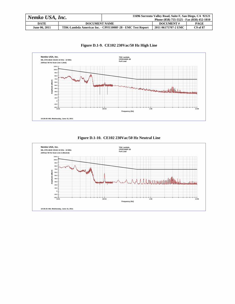
Nemko USA, Inc. 11696 Sorrento Valley Road, Suite F, San Diego, CA 92121 Phone (858) 755-5525 - Fax (858) 452-1810
DATE DOCUMENT NAME DOCUMENT # PAGE June 06, 2011 TDK-Lambda Americas Inc. - CPFE1000F-28 - EMC Test Report 2011 06175707-2 EMC C9 of 87
Figure D.1-9. CE102 230Vac/50 Hz High Line
Nemko USA, Inc.MIL-STD-461E CE102 10 KHz - 10 MHz230Vac/ 50 Hz Scan Line 1 (Hot)
10.0K 100.0K 1.0M 10.0M
Frequency (Hz)
-20.0
-10.0
0
10.0
20.0
30.0
40.0
50.0
60.0
70.0
80.0
90.0
100.0
110.0
Am
plitu
de (d
BuV
)
10:26:00 AM, Wednesday, June 15, 2011
TDK Lambda CPFE1000F-28Full Load
Figure D.1-10. CE102 230Vac/50 Hz Neutral Line
Nemko USA, Inc.MIL-STD-461E CE102 10 KHz - 10 MHz230Vac/ 50 Hz Scan Line 2 (Neutral)
10.0K 100.0K 1.0M 10.0M
Frequency (Hz)
-20.0
-10.0
0
10.0
20.0
30.0
40.0
50.0
60.0
70.0
80.0
90.0
100.0
110.0
Am
plitu
de (d
BuV
)
10:30:25 AM, Wednesday, June 15, 2011
TDK Lambda CPFE1000F-28Full Load

Nemko USA, Inc. 11696 Sorrento Valley Road, Suite F, San Diego, CA 92121 Phone (858) 755-5525 - Fax (858) 452-1810
DATE DOCUMENT NAME DOCUMENT # PAGE June 06, 2011 TDK-Lambda Americas Inc. - CPFE1000F-28 - EMC Test Report 2011 06175707-2 EMC C10 of 87
D.1.3 Conducted Emissions CE102 Equipment List
Asset No.
Description Model Number Serial # Last Cal. Cal due
422 Spectrum Analyzer, HP 8568B 2403A01672 8/20/2010 8/20/2011 825 LISN Set, Com-Power LI-400 25064 6/16/2011 6/16/2012 746 Signal Generator, HP 8648B 36421905 1/7/2011 1/7/2012 935 Oscilloscope, Agilent 54845A US40380201 9/14/2010 9/14/2011
956 10 dB (2) Attenuators,
Narda 118A/4 314090,3134
0 2/7/2011 2/7/2012 868 Isolation Transformer RTE Deltec N/A N/A N/A 870 Power Conditioner OneAC N/A N/A N/A
- 50 Ohm Termination HP 908A N/A N/A N/A