EMC connectors and electromagnetic compatibility ... EMC connectors and electromagnetic...
17
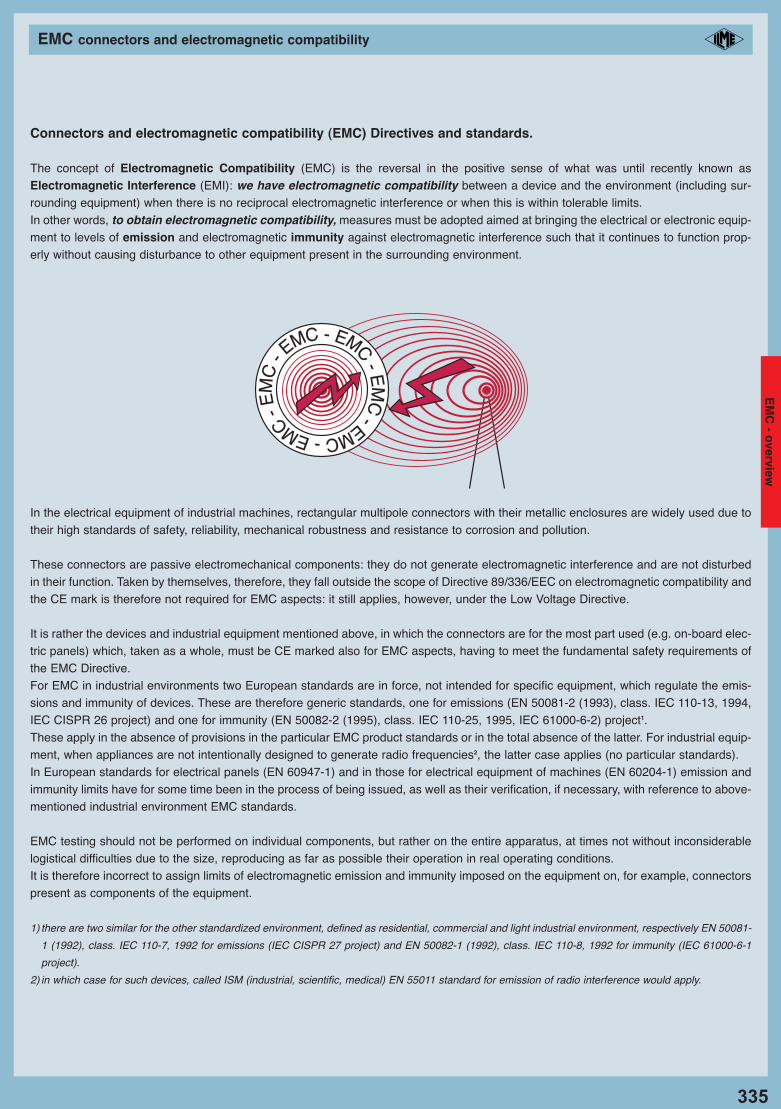
335 EMC connectors and electromagnetic compatibility Connectors and electromagnetic compatibility (EMC) Directives and standards. The concept of Electromagnetic Compatibility (EMC) is the reversal in the positive sense of what was until recently known as Electromagnetic Interference (EMI): we have electromagnetic compatibility between a device and the environment (including sur- rounding equipment) when there is no reciprocal electromagnetic interference or when this is within tolerable limits. In other words, to obtain electromagnetic compatibility, measures must be adopted aimed at bringing the electrical or electronic equip- ment to levels of emission and electromagnetic immunity against electromagnetic interference such that it continues to function prop- erly without causing disturbance to other equipment present in the surrounding environment. In the electrical equipment of industrial machines, rectangular multipole connectors with their metallic enclosures are widely used due to their high standards of safety, reliability, mechanical robustness and resistance to corrosion and pollution. These connectors are passive electromechanical components: they do not generate electromagnetic interference and are not disturbed in their function. Taken by themselves, therefore, they fall outside the scope of Directive 89/336/EEC on electromagnetic compatibility and the CE mark is therefore not required for EMC aspects: it still applies, however, under the Low Voltage Directive. It is rather the devices and industrial equipment mentioned above, in which the connectors are for the most part used (e.g. on-board elec- tric panels) which, taken as a whole, must be CE marked also for EMC aspects, having to meet the fundamental safety requirements of the EMC Directive. For EMC in industrial environments two European standards are in force, not intended for specific equipment, which regulate the emis- sions and immunity of devices. These are therefore generic standards, one for emissions (EN 50081-2 (1993), class. IEC 110-13, 1994, IEC CISPR 26 project) and one for immunity (EN 50082-2 (1995), class. IEC 110-25, 1995, IEC 61000-6-2) project 1 . These apply in the absence of provisions in the particular EMC product standards or in the total absence of the latter. For industrial equip- ment, when appliances are not intentionally designed to generate radio frequencies 2 , the latter case applies (no particular standards). In European standards for electrical panels (EN 60947-1) and in those for electrical equipment of machines (EN 60204-1) emission and immunity limits have for some time been in the process of being issued, as well as their verification, if necessary, with reference to above- mentioned industrial environment EMC standards. EMC testing should not be performed on individual components, but rather on the entire apparatus, at times not without inconsiderable logistical difficulties due to the size, reproducing as far as possible their operation in real operating conditions. It is therefore incorrect to assign limits of electromagnetic emission and immunity imposed on the equipment on, for example, connectors present as components of the equipment. 1) there are two similar for the other standardized environment, defined as residential, commercial and light industrial environment, respectively EN 50081- 1 (1992), class. IEC 110-7, 1992 for emissions (IEC CISPR 27 project) and EN 50082-1 (1992), class. IEC 110-8, 1992 for immunity (IEC 61000-6-1 project). 2)in which case for such devices, called ISM (industrial, scientific, medical) EN 55011 standard for emission of radio interference would apply. E M C - E M C - E M C - E M C - E M C - E M C - EMC - overview
-
Upload
trinhtuong -
Category
Documents
-
view
238 -
download
0
Transcript of EMC connectors and electromagnetic compatibility ... EMC connectors and electromagnetic...
335
EMC connectors and electromagnetic compatibility
Connectors and electromagnetic compatibility (EMC) Directives and standards.
The concept of Electromagnetic Compatibility (EMC) is the reversal in the positive sense of what was until recently known asElectromagnetic Interference (EMI): we have electromagnetic compatibility between a device and the environment (including sur-rounding equipment) when there is no reciprocal electromagnetic interference or when this is within tolerable limits.In other words, to obtain electromagnetic compatibility, measures must be adopted aimed at bringing the electrical or electronic equip-ment to levels of emission and electromagnetic immunity against electromagnetic interference such that it continues to function prop-erly without causing disturbance to other equipment present in the surrounding environment.
In the electrical equipment of industrial machines, rectangular multipole connectors with their metallic enclosures are widely used due totheir high standards of safety, reliability, mechanical robustness and resistance to corrosion and pollution.
These connectors are passive electromechanical components: they do not generate electromagnetic interference and are not disturbedin their function. Taken by themselves, therefore, they fall outside the scope of Directive 89/336/EEC on electromagnetic compatibility andthe CE mark is therefore not required for EMC aspects: it still applies, however, under the Low Voltage Directive.
It is rather the devices and industrial equipment mentioned above, in which the connectors are for the most part used (e.g. on-board elec-tric panels) which, taken as a whole, must be CE marked also for EMC aspects, having to meet the fundamental safety requirements ofthe EMC Directive.For EMC in industrial environments two European standards are in force, not intended for specific equipment, which regulate the emis-sions and immunity of devices. These are therefore generic standards, one for emissions (EN 50081-2 (1993), class. IEC 110-13, 1994,IEC CISPR 26 project) and one for immunity (EN 50082-2 (1995), class. IEC 110-25, 1995, IEC 61000-6-2) project1.These apply in the absence of provisions in the particular EMC product standards or in the total absence of the latter. For industrial equip-ment, when appliances are not intentionally designed to generate radio frequencies2, the latter case applies (no particular standards).In European standards for electrical panels (EN 60947-1) and in those for electrical equipment of machines (EN 60204-1) emission andimmunity limits have for some time been in the process of being issued, as well as their verification, if necessary, with reference to above-mentioned industrial environment EMC standards.
EMC testing should not be performed on individual components, but rather on the entire apparatus, at times not without inconsiderablelogistical difficulties due to the size, reproducing as far as possible their operation in real operating conditions.It is therefore incorrect to assign limits of electromagnetic emission and immunity imposed on the equipment on, for example, connectorspresent as components of the equipment.
1) there are two similar for the other standardized environment, defined as residential, commercial and light industrial environment, respectively EN 50081-
1 (1992), class. IEC 110-7, 1992 for emissions (IEC CISPR 27 project) and EN 50082-1 (1992), class. IEC 110-8, 1992 for immunity (IEC 61000-6-1
project).
2) in which case for such devices, called ISM (industrial, scientific, medical) EN 55011 standard for emission of radio interference would apply.
EMC-EMC-E
MC
- EMC - EMC
- EM
C-
EM
C - o
verview
10_Custodie EMC_GB 335-351_Custodie_EMC_GB 08/11/11 14.39 Pagina 335
336
EMC connectors and electromagnetic compatibility
Electromagnetic interference and ILME connectors.
The entry into force of the EMC Directive, with requirement for electrical and electronic equipment to comply with the levels of electro-magnetic pollution dictated by the standards, brought renewed interest in all the appropriate steps to mitigate the effects of electromag-netic interference.
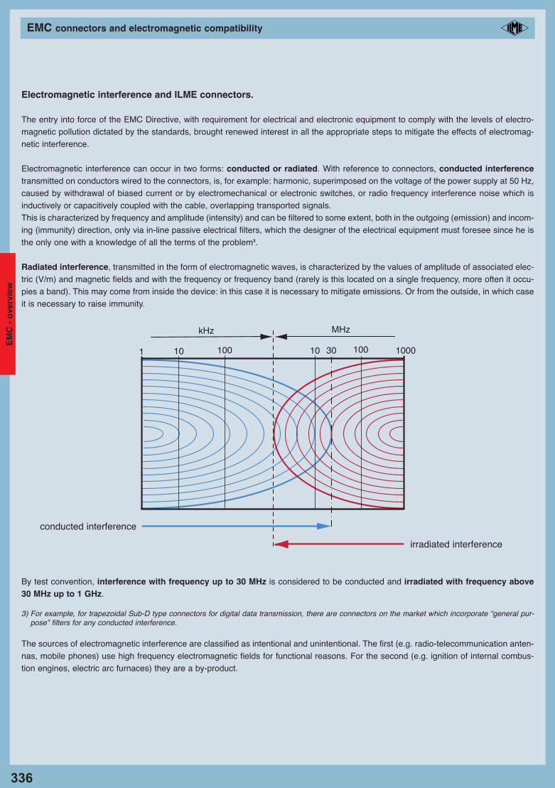
Electromagnetic interference can occur in two forms: conducted or radiated. With reference to connectors, conducted interferencetransmitted on conductors wired to the connectors, is, for example: harmonic, superimposed on the voltage of the power supply at 50 Hz,caused by withdrawal of biased current or by electromechanical or electronic switches, or radio frequency interference noise which isinductively or capacitively coupled with the cable, overlapping transported signals.This is characterized by frequency and amplitude (intensity) and can be filtered to some extent, both in the outgoing (emission) and incom-ing (immunity) direction, only via in-line passive electrical filters, which the designer of the electrical equipment must foresee since he isthe only one with a knowledge of all the terms of the problem3.
Radiated interference, transmitted in the form of electromagnetic waves, is characterized by the values of amplitude of associated elec-tric (V/m) and magnetic fields and with the frequency or frequency band (rarely is this located on a single frequency, more often it occu-pies a band). This may come from inside the device: in this case it is necessary to mitigate emissions. Or from the outside, in which caseit is necessary to raise immunity.
By test convention, interference with frequency up to 30 MHz is considered to be conducted and irradiated with frequency above30 MHz up to 1 GHz.
3) For example, for trapezoidal Sub-D type connectors for digital data transmission, there are connectors on the market which incorporate “general pur-pose” filters for any conducted interference.
The sources of electromagnetic interference are classified as intentional and unintentional. The first (e.g. radio-telecommunication anten-nas, mobile phones) use high frequency electromagnetic fields for functional reasons. For the second (e.g. ignition of internal combus-tion engines, electric arc furnaces) they are a by-product.
kHz MHz
10 100 10 10030 10001
irradiated interference
conducted interference
EM
C -
ove
rvie
w
10_Custodie EMC_GB 335-351_Custodie_EMC_GB 08/11/11 14.39 Pagina 336

337
EMC connectors and electromagnetic compatibility
In most industrial applications, compared to the overall EMC issues of a device, connectors (inserts + enclosures), taken by themselves,are not the priority concern of the designer.The enclosures of the low-frequency industrial connectors, taking shape as a barrier to a “shell”, are implicitly a “peripheral” aspect: thedesigner of electrical equipment / electronics will take care first of all the “core” of the EMC problem, that of the active components toʻinside of your system by limiting the emissions and enhance immunity.In fact, to have significant problems due to radiation through the opening constituted by a connector enclosure on a control panel, theremust be a particularly “efficient” radiofrequency source inside the panel. Essentially, significant design errors must have been committedregarding the EMC of the entire equipment.
In certain cases the coupling of connectors may constitute the weak link in the chain, for example where it is not possible for functionalreasons to further reduce interference of the electronics inside the control panel. In these cases one must rely on the efficiency of theshield. Even if the equipment manufacturer uses shielded fabrication and high quality shielded cables, continuity and homogeneity of suchshielding could be significantly degraded precisely in the passage between mobile connector and panel.In dealing with electromagnetic compatibility of electrical equipment of an industrial machine, a second aspect to be addressed as a pri-ority is the presence of large quantities of interface cabling.In these cases, the significant attenuation of the shield necessary for the cables must not be jeopardised by the connector enclosuresdue to imperfect earthing of the cable shield.
It should nevertheless be pointed out that increasing shielding may not be sufficient to solve possible problems and should be consid-ered as a complementary choice.
Electromagnetic shielding of connectors: fundamental principles.
To considering electromagnetic compatibility of an electrical/electronic device in the final verification rather than in the design phasealmost always leads to a substantial increase in overall development time and costs.
The designer who deals with electromagnetic compatibility issues should use the same rules and the same precautions regardless ofwhether the equipment is subsequently shielded. Numerous products meet electromagnetic compatibility standards without the use ofshielding. However, when all other limiting interventions are impossible or uneconomical, recourse to increased efficiency of the electro-magnetic shield is the only answer.
An electromagnetic shield is a barrier to the transmission of electromagnetic fields. To generalise the concept to include conductedemissions, a filter can be considered as a shield. We will restrict ourselves here to considering a shield as a barrier to radiated emissions.The metallic containers which completely enclose an electrical/electronic device or a part thereof constitute an electromagnetic shield,with the task of preventing the emissions of electrical/electronic devices or a part thereof to radiate outside the equipment container itself.A cable connected to a device is part of the same for the purposes of electromagnetic compatibility. A flexible multicore cable is shieldedby surrounding the insulated conductors with a conductive metal mesh.An electromagnetic shield is characterized by a parameter which measures its efficiency.Attenuation of the shield is the ratio between the radiated power generated inside a device and the residual radiated power outside theunit. Attenuation introduced by a shield can be measured by comparing the absence and presence of the shield. Shielding attenuationis measured in dB (decibels). 20 dB is equivalent to an order of magnitude, i.e. attenuation of a factor of 10, 40 dB = attenuation of afactor of 100, etc.
EM
C - o
verview
10_Custodie EMC_GB 335-351_Custodie_EMC_GB 08/11/11 14.39 Pagina 337
338
EMC connectors and electromagnetic compatibility
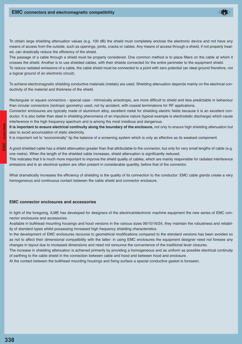
To obtain large shielding attenuation values (e.g. 100 dB) the shield must completely enclose the electronic device and not have anymeans of access from the outside, such as openings, joints, cracks or cables. Any means of access through a shield, if not properly treat-ed, can drastically reduce the efficiency of the shield.The passage of a cable through a shield must be properly considered. One common method is to place filters on the cable at which itcrosses the shield. Another is to use shielded cables, with their shields connected for the entire perimeter to the equipment shield.To reduce radiated emissions of a cable, the cable shield must be connected to a point with zero potential (an ideal ground therefore, nota logical ground of an electronic circuit).
To achieve electromagnetic shielding conductive materials (metals) are used. Shielding attenuation depends mainly on the electrical con-ductivity of the material and thickness of the shield.
Rectangular or square connectors - special case - intrinsically anisotropic, are more difficult to shield and less predictable in behaviourthan circular connectors (isotropic geometry) used, not by accident, with coaxial terminations for RF applications.Connector enclosures are typically made of aluminium alloy, excellent metal for shielding electric fields because it is an excellent con-ductor. It is also better than steel in shielding phenomena of an impulsive nature (typical example is electrostatic discharge) which causeinterference in the high frequency spectrum and is among the most insidious and dangerous.It is important to ensure electrical continuity along the boundary of the enclosure, not only to ensure high shielding attenuation butalso to avoid accumulation of static electricity.It is important not to “economically” tip the balance of a screening system which is only as effective as its weakest component.
A good shielded cable has a shield attenuation greater than that attributable to the connector, but only for very small lengths of cable (e.g.one metre). When the length of the shielded cable increases, shield attenuation is significantly reduced.This indicates that it is much more important to improve the shield quality of cables, which are mainly responsible for radiated interferenceemissions and in an electrical system are often present in considerable quantity, before that of the connector.
What dramatically increases the efficiency of shielding is the quality of its connection to the conductor: EMC cable glands create a veryhomogeneous and continuous contact between the cable shield and connector enclosure.
EMC connector enclosures and accessories
In light of the foregoing, ILME has developed for designers of the electrical/electronic machine equipment the new series of EMC con-nector enclosures and accessories.Available in bulkhead mounting housings and hood versions in the various sizes 06/10/16/24, they maintain the robustness and reliabil-ity of standard types whilst possessing increased high frequency shielding characteristics.In the development of EMC enclosures recourse to geometrical modifications compared to the standard versions has been avoided soas not to affect their dimensional compatibility with the latter: in using EMC enclosures the equipment designer need not foresee anychanges in layout due to increased dimensions and need not renounce the convenience of the traditional lever closures.The increase in shielding attenuation is achieved primarily by providing a homogeneous and as uniform as possible electrical continuityof earthing to the cable shield in the connection between cable and hood and between hood and enclosure.At the contact between the bulkhead mounting housings and fixing surface a special conductive gasket is foreseen.
EM
C -
ove
rvie
w
10_Custodie EMC_GB 335-351_Custodie_EMC_GB 08/11/11 14.39 Pagina 338
339
EMC connectors and electromagnetic compatibility
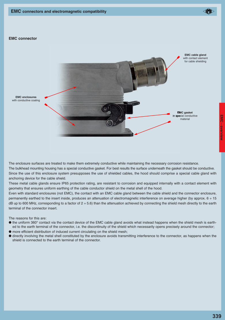
The enclosure surfaces are treated to make them extremely conductive while maintaining the necessary corrosion resistance.The bulkhead mounting housing has a special conductive gasket. For best results the surface underneath the gasket should be conductive.Since the use of this enclosure system presupposes the use of shielded cables, the hood should comprise a special cable gland withanchoring device for the cable shield.These metal cable glands ensure IP65 protection rating, are resistant to corrosion and equipped internally with a contact element withgeometry that ensures uniform earthing of the cable conductor shield on the metal shell of the hood.Even with standard enclosures (not EMC), the contact with an EMC cable gland between the cable shield and the connector enclosure,permanently earthed to the insert inside, produces an attenuation of electromagnetic interference on average higher (by approx. 6 ÷ 15dB up to 600 MHz, corresponding to a factor of 2 ÷ 5.6) than the attenuation achieved by connecting the shield mesh directly to the earthterminal of the connector insert.
The reasons for this are:● the uniform 360° contact via the contact device of the EMC cable gland avoids what instead happens when the shield mesh is earth-
ed to the earth terminal of the connector, i.e. the discontinuity of the shield which necessarily opens precisely around the connector;● more efficient distribution of induced current circulating on the shield mesh;● directly involving the metal shell constituted by the enclosure avoids transmitting interference to the connector, as happens when the
shield is connected to the earth terminal of the connector.
EMC connector
EMC gasketin special conductive
material
EMC enclosureswith conductive coating
EMC cable glandwith contact element for cable shielding
EM
C - o
verview
10_Custodie EMC_GB 335-351_Custodie_EMC_GB 08/11/11 14.39 Pagina 339
340
EMC connectors and electromagnetic compatibility
Experimental tests
Tests for measurement of the shielding of ILME special EMC enclosures for multipole rectangular connectors for industrial use were con-ducted at the CESI EMC Laboratory in Milan, national notified body for certification under the EMC Directive.Shielding attenuation of a component is defined as the ratio of the power radiated within the component and the maximum interferencepower outside the component in the room (VG 95214-11). For a connector it can be expressed, in analogy with cables, as a function of transfer impedance, which is the ratio between the voltageinduced in the shield and the current flowing outside the same. The transfer impedance measurement is a widely used and acceptedmethod to determine shielding attenuation of coaxial cables and connectors. Only recently, due to the increase in digital data transmis-sion speeds and the increase in frequencies of transmitted signals, the issue of identifying efficient and repeatable methods for measur-ing shielding efficiency, also for connectors traditionally considered low frequency, has been addressed at a regulatory level.
An experimental method for determining surface transfer impedance of coupled low frequency connectors is still being studied by IEC.
The method chosen by ILME for verification of its system of EMC enclosures and accessories is the line injection method based onGerman military standards VG 95214-10 and VG 95214-11.
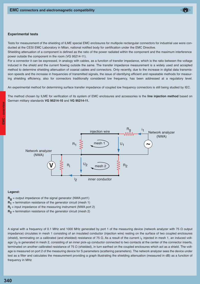
Legend:
Rg = output impedance of the signal generator (NWA port1)R1 = termination resistance of the generator circuit (mesh 1)Ri = input impedance of the measuring instrument (NWA port 2)R2 = termination resistance of the generator circuit (mesh 2)
A signal with a frequency of 0.1 MHz and 1000 MHz generated by port 1 of the measuring device (network analyzer with 75 Ω outputimpedance) circulates in mesh 1 consisting of an insulated conductor (injection wire) resting on the surface of two coupled enclosures(shield), terminating on a calibrated (and shielded) resistance of 75 Ω. As a result of the current i1 injected in mesh 1, an induced volt-age U2 is generated in mesh 2, consisting of an inner pick-up conductor connected to two contacts at the center of the connector inserts,terminated on another calibrated resistance of 75 Ω (shielded), in turn earthed on the coupled enclosures which act as a shield. The volt-age is measured on port 2 of the measuring device for S parameters (scattering parameters). The network analyzer sees the device undertest as a filter and calculates the measurement providing a graph illustrating the shielding attenuation (measured in dB) as a function offrequency in MHz
mesh 1
mesh 2
injection wire
inner conductor
U2
i2
U1
R2Ri
i1
Network analyzer (NWA)
Network analyzer (NWA)
R1
Rg
EM
C -
ove
rvie
w
10_Custodie EMC_GB 335-351_Custodie_EMC_GB 08/11/11 14.39 Pagina 340
341
EMC connectors and electromagnetic compatibility
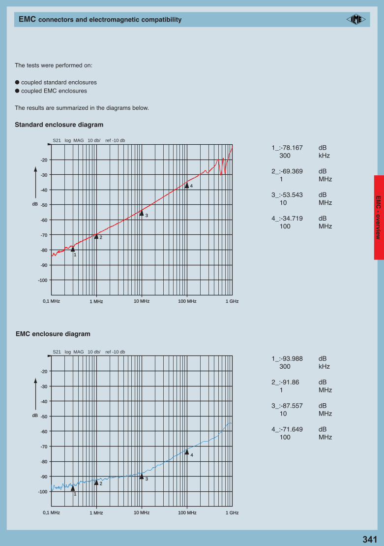
The tests were performed on:
● coupled standard enclosures● coupled EMC enclosures
The results are summarized in the diagrams below.
Standard enclosure diagram
0,1 MHz0,1 MHz 1 MHz1 MHz 10 MHz10 MHz 100 MHz100 MHz 1 GHz1 GHz
dBdB
-20-20
-30-30
-40-40
-50-50
-60-60
-70-70
-80-80
-90-90
-100-100
2
1
3
4
S21 log MAG 10 db/ ref -10 db
0,1 MHz0,1 MHz 1 MHz1 MHz 10 MHz10 MHz 100 MHz100 MHz 1 GHz1 GHz
dBdB
-20-20
-30-30
-40-40
-50-50
-60-60
-70-70
-80-80
-90-90
-100-100
2
1
3
4
S21 log MAG 10 db/ ref -10 db
1_:-78.167 dB300 kHz
2_:-69.369 dB1 MHz
3_:-53.543 dB10 MHz
4_:-34.719 dB100 MHz
1_:-93.988 dB300 kHz
2_:-91.86 dB1 MHz
3_:-87.557 dB10 MHz
4_:-71.649 dB100 MHz
EMC enclosure diagram
EM
C - o
verview
10_Custodie EMC_GB 335-351_Custodie_EMC_GB 08/11/11 14.39 Pagina 341
342
EMC connectors and electromagnetic compatibility
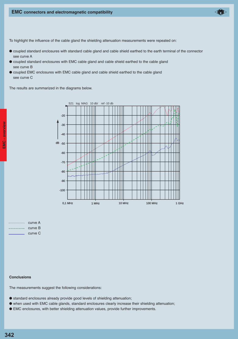
To highlight the influence of the cable gland the shielding attenuation measurements were repeated on:
● coupled standard enclosures with standard cable gland and cable shield earthed to the earth terminal of the connectorsee curve A
● coupled standard enclosures with EMC cable gland and cable shield earthed to the cable glandsee curve B
● coupled EMC enclosures with EMC cable gland and cable shield earthed to the cable glandsee curve C
The results are summarized in the diagrams below.
Conclusions
The measurements suggest the following considerations:
● standard enclosures already provide good levels of shielding attenuation;● when used with EMC cable glands, standard enclosures clearly increase their shielding attenuation;● EMC enclosures, with better shielding attenuation values, provide further improvements.
0,1 MHz0,1 MHz 1 MHz1 MHz 10 MHz10 MHz 100 MHz100 MHz 1 GHz1 GHz
dBdB
-20-20
-30-30
-40-40
-50-50
-60-60
-70-70
-80-80
-90-90
-100-100
S21 log MAG 10 db/ ref -10 db
curve Acurve Bcurve C
EM
C -
ove
rvie
w
10_Custodie EMC_GB 335-351_Custodie_EMC_GB 08/11/11 14.39 Pagina 342
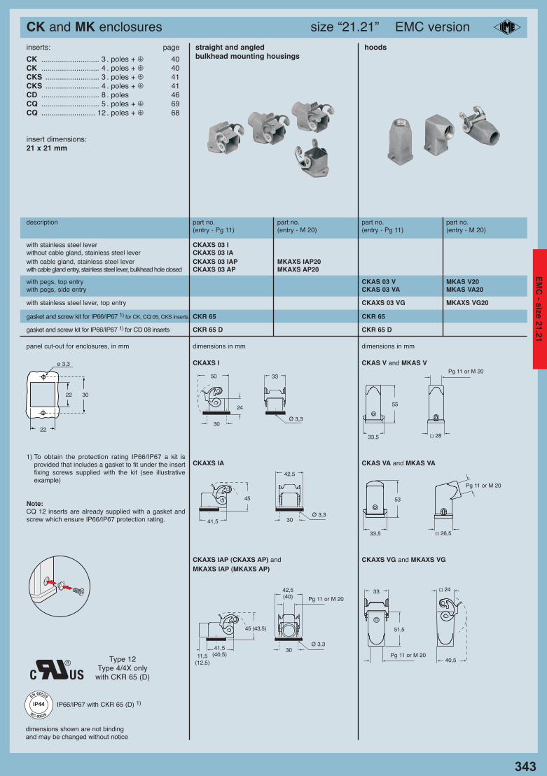
CK and MK enclosures size “21.21” EMC version
dimensions shown are not bindingand may be changed without notice
description part no. part no. part no. part no.(entry - Pg 11) (entry - M 20) (entry - Pg 11) (entry - M 20)
straight and angled hoodsbulkhead mounting housings
with stainless steel lever CKAXS 03 Iwithout cable gland, stainless steel lever CKAXS 03 IAwith cable gland, stainless steel lever CKAXS 03 IAP MKAXS IAP20with cable gland entry, stainless steel lever, bulkhead hole closed CKAXS 03 AP MKAXS AP20
with pegs, top entry CKAS 03 V MKAS V20with pegs, side entry CKAS 03 VA MKAS VA20
with stainless steel lever, top entry CKAXS 03 VG MKAXS VG20
gasket and screw kit for IP66/IP67 1) for CK, CQ 05, CKS inserts CKR 65 CKR 65
inserts: page
CK ............................ 3 . poles + m 40CK ............................ 4 . poles + m 40CKS .......................... 3 . poles + m 41CKS .......................... 4 . poles + m 41CD ............................ 8 . poles 46CQ ............................ 5 . poles + m 69CQ .......................... 12 . poles + m 68
insert dimensions:21 x 21 mm
panel cut-out for enclosures, in mm dimensions in mm dimensions in mm
CKAXS I CKAS V and MKAS V
CKAXS IA CKAS VA and MKAS VA
CKAXS IAP (CKAXS AP) and CKAXS VG and MKAXS VGMKAXS IAP (MKAXS AP)
22 30
22
ø 3,3
24
Ø 3,3
33
30
42,5
30
45
Ø 3,341,5
42,5(40)
41,5(40,5)
45 (43,5)
Ø 3,3
11,5(12,5)
Pg 11 or M 20
30
50
1) To obtain the protection rating IP66/IP67 a kit isprovided that includes a gasket to fit under the insertfixing screws supplied with the kit (see illustrativeexample)
Note: CQ 12 inserts are already supplied with a gasket andscrew which ensure IP66/IP67 protection rating.
� 2433
51,5
Pg 11 or M 2040,5
gasket and screw kit for IP66/IP67 1) for CD 08 inserts CKR 65 D CKR 65 D
Type 12Type 4/4X only
with CKR 65 (D)
� 2833,5
55
Pg 11 or M 20
� 26,533,5
53
Pg 11 or M 20
343
IP44IP44
EN 60529
IEC 60529
IP44IP44 IP66/IP67 with CKR 65 (D) 1)
EM
C - size 21.21
10_Custodie EMC_GB 335-351_Custodie_EMC_GB 08/11/11 14.39 Pagina 343

CQ enclosures size “32.13” EMC version
dimensions shown are not binding
and may be changed without notice
inserts: page
CQ 08 .................. 8. poles + m 70
CQ 04/2 ................ 4. poles + 2 poles + m 71
- metallic insulating enclosures
bulkhead mounting housing with single lever hood with 2 pegs
description part no. entry part no. entry
Pg Pg
with lever CQS 08 I
without cable gland entry, angled, with lever CQS 08 IA
with cable gland entry, angled, with lever CQS 08 IAP 21
CQS I CQS VA
with pegs, side entry ** CQS 08 VA 16
48
35
28,7
54
Pg 16
with pegs, top entry ** CQS 08 V 21
panel cut-out for CQS I enclosure, in mm
27
23
32.2
13.4
48
15
Pg 21
28,7
35
54
NEW NEW
** Pg male thread on enclosure exterior dimensions in mm dimensions in mm
4618,5
19,5
28,7
34
CR 08 EMC
Note:
when using series “CQS 08” enclosures, replace the
gasket provided with male inserts with the conductive
gasket “CR 08 EMC”.
panel cut-out for CQS IA - CQS IAP enclosure, in mm CQS IA CQS V
46
38
39,5
54,5
17,8
46
30
34,5
37,25
CQS IAP
46
38
39,5
54,5
17,8
46
30
34,5
37,25
15
Pg 21
20,25
27
23
32.2
23
27
27
27
344
IP66IP66IP67IP67
EN 60529
IEC 60529
EM
C
- s
ize
32.1
3
10_Custodie EMC_GB 335-351_Custodie_EMC_GB 08/11/11 14.39 Pagina 344
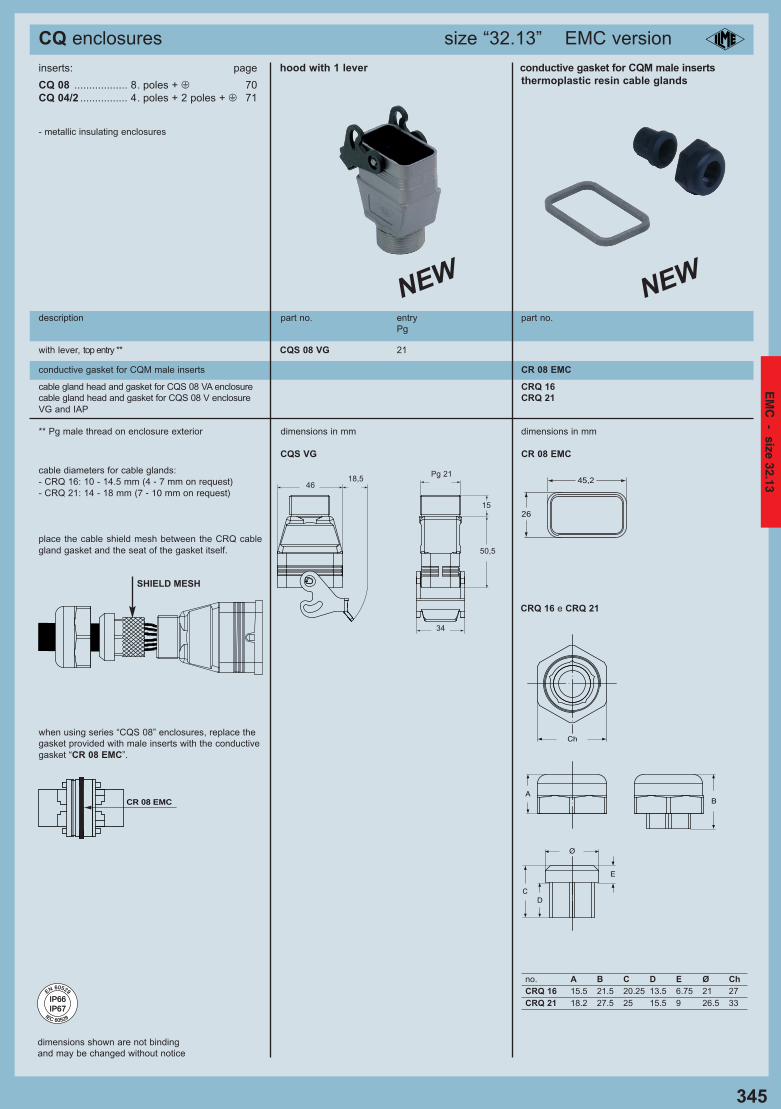
CQ enclosures size “32.13” EMC version
dimensions shown are not binding
and may be changed without notice
inserts: page
CQ 08 .................. 8. poles + m 70
CQ 04/2 ................ 4. poles + 2 poles + m 71
- metallic insulating enclosures
description part no. entry part no.
Pg
with lever, top entry ** CQS 08 VG 21
conductive gasket for CQM male inserts CR 08 EMC
CQS VG CR 08 EMC
CRQ 16 e CRQ 21
26
45,2
cable gland head and gasket for CQS 08 VA enclosure CRQ 16
cable gland head and gasket for CQS 08 V enclosure CRQ 21
VG and IAP
** Pg male thread on enclosure exterior dimensions in mm dimensions in mm
NEW NEW
cable diameters for cable glands:
- CRQ 16: 10 - 14.5 mm (4 - 7 mm on request)- CRQ 21: 14 - 18 mm (7 - 10 mm on request)
CR 08 EMC
when using series “CQS 08” enclosures, replace the
gasket provided with male inserts with the conductive
gasket “CR 08 EMC”.
hood with 1 lever conductive gasket for CQM male inserts thermoplastic resin cable glands
46
15
18,5
50,5
Pg 21
34
no. A B C D E Ø Ch
CRQ 16 15.5 21.5 20.25 13.5 6.75 21 27
CRQ 21 18.2 27.5 25 15.5 9 26.5 33
place the cable shield mesh between the CRQ cable
gland gasket and the seat of the gasket itself.
SHIELD MESH
345
IP66IP66IP67IP67
EN 60529
IEC 60529
EM
C - size 32.13
10_Custodie EMC_GB 335-351_Custodie_EMC_GB 08/11/11 14.39 Pagina 345
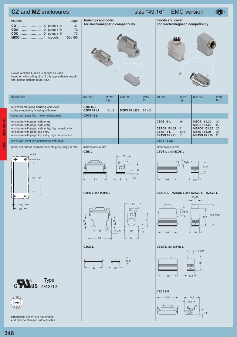
CZ and MZ enclosures size “49.16” EMC version
dimensions shown are not bindingand may be changed without notice
inserts: page
CD .......................... 15 poles + m 47CDA ........................ 10 poles + m 72CDC ........................ 10 poles + m 73MIXO ........................ 1 module 156÷195
Cover versions L and LG cannot be used together with coding pins. If this application is requi-red, please contact ILME SpA.
description part no. entry part no. entry part no. entry part no. entryPg M Pg M
housings and cover hoods and coverfor electromagnetic compatibility for electromagnetic compatibility
enclosure with pegs, side entry CZOS 15 L 16 MZOS 15 L20 20enclosure with pegs, side entry MZOS 15 L25 25enclosure with pegs, side entry, high construction CZAOS 15 L21 21 MZAOS 15 L25 25enclosure with pegs, top entry CZVS 15 L 13.5 MZVS 15 L20 20enclosure with pegs, top entry, high construction CZAVS 15 L21 21 MZAVS 15 L25 25
bulkhead mounting housing with lever CZIS 15 L —-surface mounting housing with lever CZPS 15 L2 16 x 2 MZPS 15 L225 25 x 2
panel cut-out for bulkhead mounting housings in mm dimensions in mm dimensions in mm
57 70
17,5
23
ø 3,4
cover with pegs (for 1 lever enclosures) CZCS 15 L
cover with lever (for enclosures with pegs) CZCS 15 LG
Pg/M
29,463
54,5
63
Pg/M
29,4
62
83
53
32
27
5,5
48
85
PgM
PgM
62
40
50
4
52
Ø 4,5
15,5
63 29,4
14
75,5 54,5
29,4
CZIS L CZOS L and MZOS L
CZPS L and MZPS L
CZCS L
CZAOS L - MZAOS L and CZAVS L - MZAVS L
CZVS L and MZVS L
Pg/M
3663
64,5
Pg/M79,5 max
CZCS LG
Type 4/4X/12
346
IP66IP66
EN 60529
IEC 60529
EM
C
- s
ize
49.1
6
10_Custodie EMC_GB 335-351_Custodie_EMC_GB 08/11/11 14.39 Pagina 346
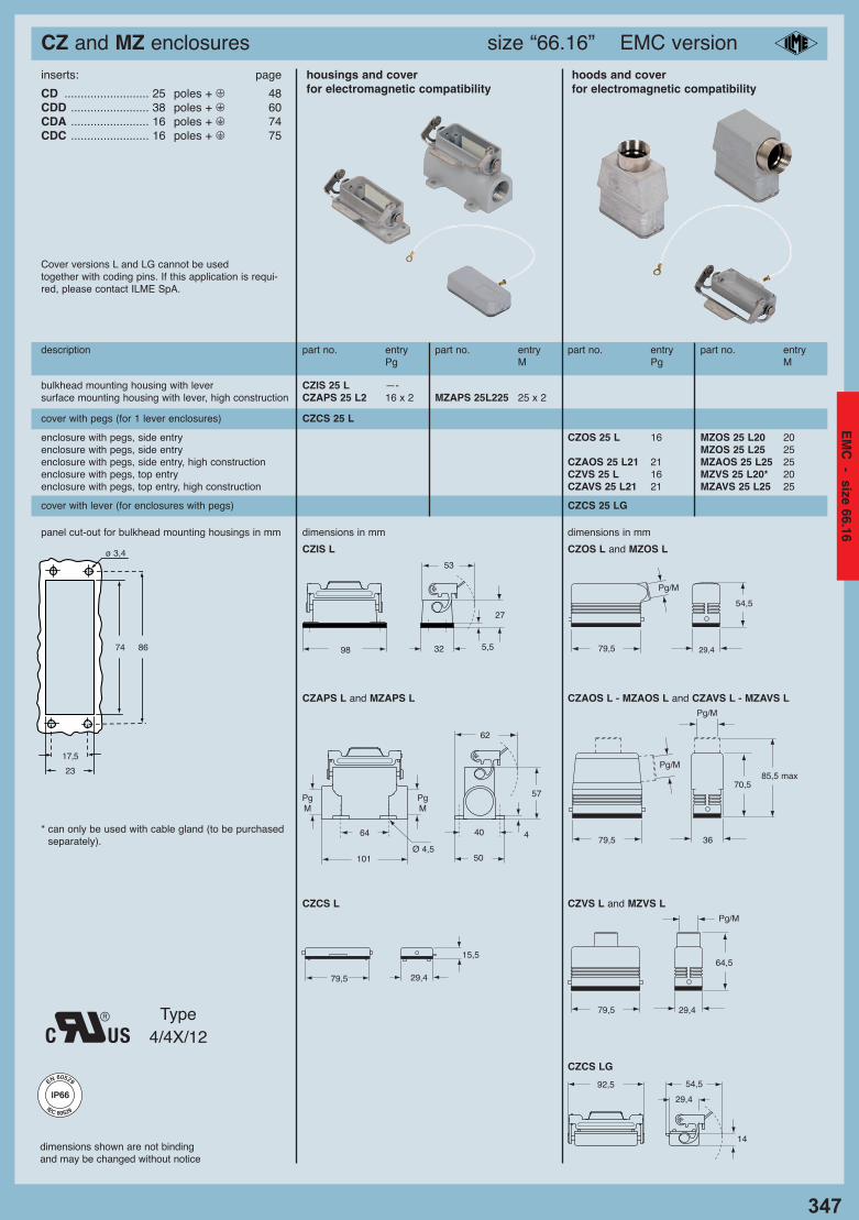
CZ and MZ enclosures size “66.16” EMC version
347
dimensions shown are not bindingand may be changed without notice
inserts: page
CD .......................... 25 poles + m 48CDD ........................ 38 poles + m 60CDA ........................ 16 poles + m 74CDC ........................ 16 poles + m 75
Cover versions L and LG cannot be used together with coding pins. If this application is requi-red, please contact ILME SpA.
description part no. entry part no. entry part no. entry part no. entryPg M Pg M
housings and cover hoods and coverfor electromagnetic compatibility for electromagnetic compatibility
bulkhead mounting housing with lever CZIS 25 L —-surface mounting housing with lever, high construction CZAPS 25 L2 16 x 2 MZAPS 25L225 25 x 2
enclosure with pegs, side entry CZOS 25 L 16 MZOS 25 L20 20enclosure with pegs, side entry MZOS 25 L25 25enclosure with pegs, side entry, high construction CZAOS 25 L21 21 MZAOS 25 L25 25enclosure with pegs, top entry CZVS 25 L 16 MZVS 25 L20* 20enclosure with pegs, top entry, high construction CZAVS 25 L21 21 MZAVS 25 L25 25
cover with pegs (for 1 lever enclosures) CZCS 25 L
cover with lever (for enclosures with pegs) CZCS 25 LG
panel cut-out for bulkhead mounting housings in mm dimensions in mm dimensions in mm
74 86
17,5
23
ø 3,4 CZIS L CZOS L and MZOS L
CZAPS L and MZAPS L
CZCS L
CZAOS L - MZAOS L and CZAVS L - MZAVS L
CZVS L and MZVS L
CZCS LG
* can only be used with cable gland (to be purchasedseparately).
Type 4/4X/12
98
53
32
27
5,5
64
101
PgM
PgM
62
40
50
4
57
Ø 4,5
15,5
79,5 29,4
Pg/M
29,479,5
54,5
79,5
Pg/M
29,4
64,5
14
92,5 54,5
29,4
Pg/M
3679,5
70,5
Pg/M85,5 max
IP66IP66
EN 60529
IEC 60529
EM
C - size 66.16
10_Custodie EMC_GB 335-351_Custodie_EMC_GB 08/11/11 14.39 Pagina 347
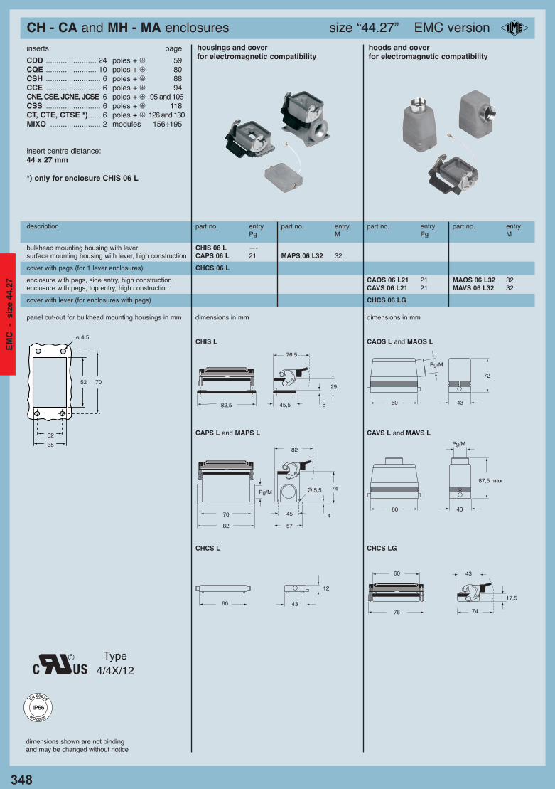
CH - CA and MH - MA enclosures size “44.27” EMC version
348
dimensions shown are not bindingand may be changed without notice
description part no. entry part no. entry part no. entry part no. entryPg M Pg M
housings and cover hoods and coverfor electromagnetic compatibility for electromagnetic compatibility
enclosure with pegs, side entry, high construction CAOS 06 L21 21 MAOS 06 L32 32enclosure with pegs, top entry, high construction CAVS 06 L21 21 MAVS 06 L32 32
cover with pegs (for 1 lever enclosures) CHCS 06 L
cover with lever (for enclosures with pegs) CHCS 06 LG
bulkhead mounting housing with lever CHIS 06 L —-surface mounting housing with lever, high construction CAPS 06 L 21 MAPS 06 L32 32
inserts: page
CDD ........................ 24 poles + m 59CQE ........................ 10 poles + m 80CSH .......................... 6 poles + m 88CCE .......................... 6 poles + m 94CNE, CSE, JCNE, JCSE 6 poles + m 95 and 106CSS .......................... 6 poles + m 118CT, CTE, CTSE *)...... 6 poles + m 126 and 130MIXO ........................ 2 modules 156÷195
insert centre distance: 44 x 27 mm
*) only for enclosure CHIS 06 L
panel cut-out for bulkhead mounting housings in mm dimensions in mm dimensions in mm
CHIS L CAOS L and MAOS L
CAPS L and MAPS L CAVS L and MAVS L
CHCS L CHCS LG
52 70
32
35
ø 4,5
82,5
76,5
45,5 6
29
70
82
Pg/M
82
45
57
4
74Ø 5,5
Pg/M
4360
72
Pg/M
4360
87,5 max
12
60 4317,5
60 43
76 74
Type 4/4X/12
IP66IP66
EN 60529
IEC 60529
EM
C
- s
ize
44.2
7
10_Custodie EMC_GB 335-351_Custodie_EMC_GB 08/11/11 14.39 Pagina 348
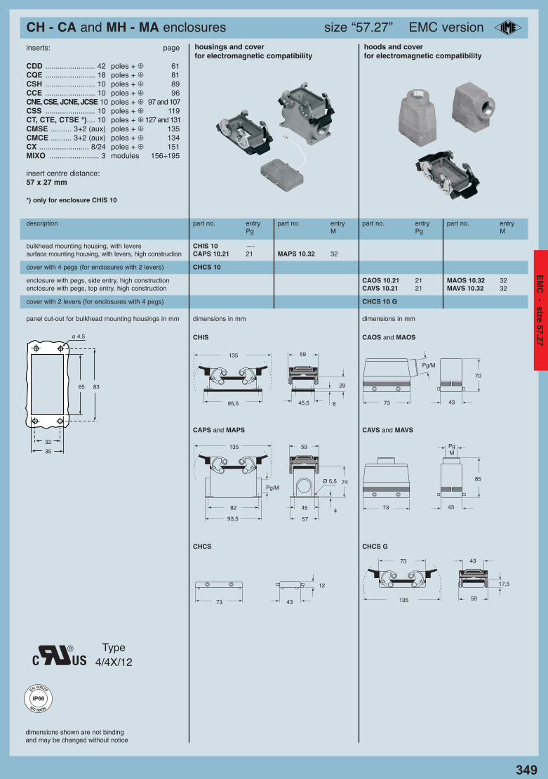
CH - CA and MH - MA enclosures size “57.27” EMC version
349
dimensions shown are not bindingand may be changed without notice
description part no. entry part no. entry part no. entry part no. entryPg M Pg M
housings and cover hoods and coverfor electromagnetic compatibility for electromagnetic compatibility
enclosure with pegs, side entry, high construction CAOS 10.21 21 MAOS 10.32 32enclosure with pegs, top entry, high construction CAVS 10.21 21 MAVS 10.32 32
cover with 4 pegs (for enclosures with 2 levers) CHCS 10
cover with 2 levers (for enclosures with 4 pegs) CHCS 10 G
bulkhead mounting housing, with levers CHIS 10 —-surface mounting housing, with levers, high construction CAPS 10.21 21 MAPS 10.32 32
panel cut-out for bulkhead mounting housings in mm dimensions in mm dimensions in mm
CHIS CAOS and MAOS
CAPS and MAPS CAVS and MAVS
CHCS CHCS G
65 83
32
35
ø 4,5
95,5
59
45,5 6
29
135
82
93,5
Pg/M
45
57
4
74Ø 5,5
59135
Pg/M
4373
70
PgM
4373
85
inserts: page
CDD ........................ 42 poles + m 61CQE ........................ 18 poles + m 81CSH ........................ 10 poles + m 89CCE ........................ 10 poles + m 96CNE, CSE, JCNE, JCSE 10 poles + m 97 and 107CSS ........................ 10 poles + m 119CT, CTE, CTSE *).... 10 poles + m 127 and 131CMSE .......... 3+2 (aux) poles + m 135CMCE .......... 3+2 (aux) poles + m 134CX ........................ 8/24 poles + m 151MIXO ........................ 3 modules 156÷195
insert centre distance: 57 x 27 mm
*) only for enclosure CHIS 10
12
73 43
17,5
73 43
135 59
Type 4/4X/12
IP66IP66
EN 60529
IEC 60529
EM
C - size 57.27
10_Custodie EMC_GB 335-351_Custodie_EMC_GB 08/11/11 14.39 Pagina 349
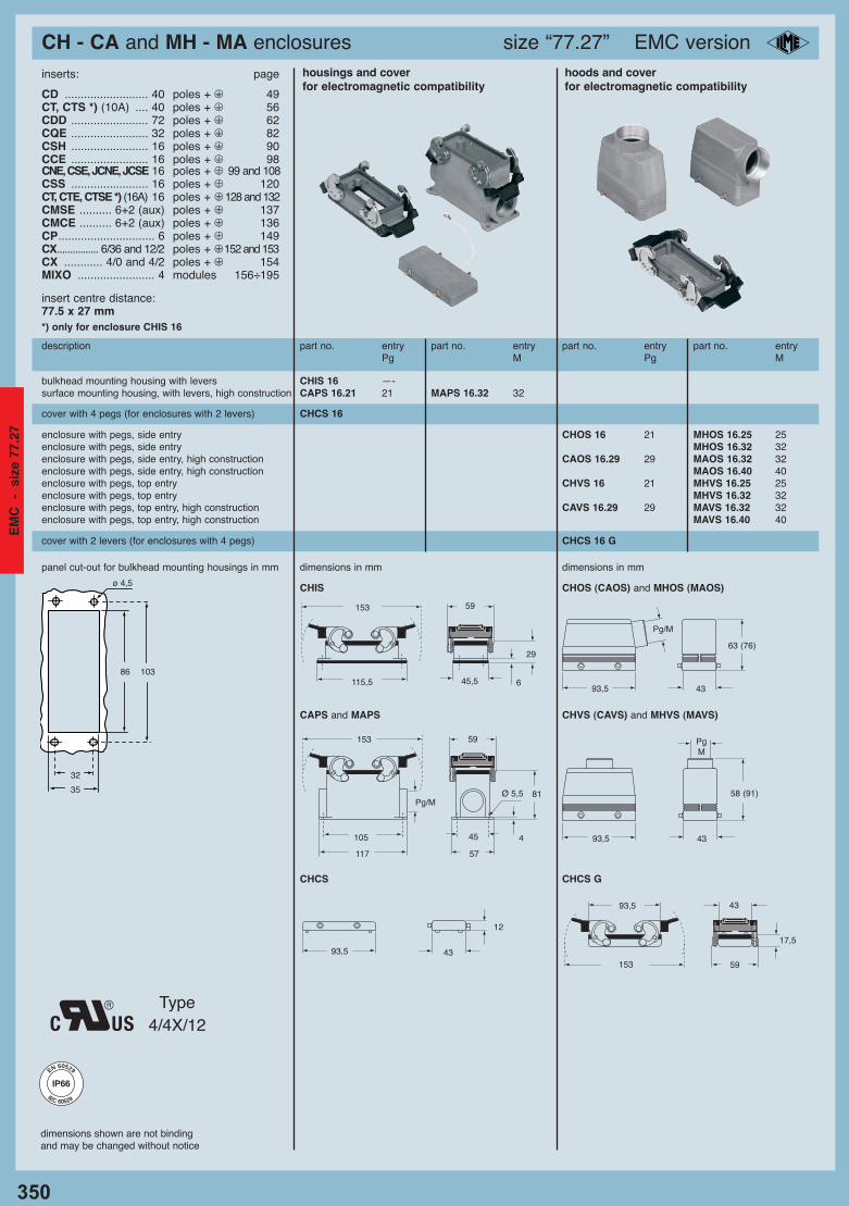
CH - CA and MH - MA enclosures size “77.27” EMC version
350
dimensions shown are not bindingand may be changed without notice
description part no. entry part no. entry part no. entry part no. entryPg M Pg M
housings and cover hoods and coverfor electromagnetic compatibility for electromagnetic compatibility
bulkhead mounting housing with levers CHIS 16 —-surface mounting housing, with levers, high construction CAPS 16.21 21 MAPS 16.32 32
enclosure with pegs, side entry CHOS 16 21 MHOS 16.25 25enclosure with pegs, side entry MHOS 16.32 32enclosure with pegs, side entry, high construction CAOS 16.29 29 MAOS 16.32 32enclosure with pegs, side entry, high construction MAOS 16.40 40enclosure with pegs, top entry CHVS 16 21 MHVS 16.25 25enclosure with pegs, top entry MHVS 16.32 32enclosure with pegs, top entry, high construction CAVS 16.29 29 MAVS 16.32 32enclosure with pegs, top entry, high construction MAVS 16.40 40
cover with 4 pegs (for enclosures with 2 levers) CHCS 16
inserts: page
CD .......................... 40 poles + m 49CT, CTS *) (10A) .... 40 poles + m 56CDD ........................ 72 poles + m 62CQE ........................ 32 poles + m 82CSH ........................ 16 poles + m 90CCE ........................ 16 poles + m 98CNE, CSE, JCNE, JCSE 16 poles + m 99 and 108CSS ........................ 16 poles + m 120CT, CTE, CTSE *) (16A) 16 poles + m 128 and 132CMSE .......... 6+2 (aux) poles + m 137CMCE .......... 6+2 (aux) poles + m 136CP.............................. 6 poles + m 149CX................ 6/36 and 12/2 poles + m152 and 153CX ............ 4/0 and 4/2 poles + m 154MIXO ........................ 4 modules 156÷195
insert centre distance: 77.5 x 27 mm*) only for enclosure CHIS 16
cover with 2 levers (for enclosures with 4 pegs) CHCS 16 G
panel cut-out for bulkhead mounting housings in mm dimensions in mm dimensions in mm
CHIS CHOS (CAOS) and MHOS (MAOS)
CAPS and MAPS CHVS (CAVS) and MHVS (MAVS)
CHCS CHCS G
86 103
32
35
ø 4,5
115,5
59
45,5 6
29
153
105
117
Pg/M
45
57
4
81Ø 5,5
59153 PgM
4393,5
58 (91)
12
93,5 4317,5
93,5 43
153 59
Type 4/4X/12
Pg/M
4393,5
63 (76)
IP66IP66
EN 60529
IEC 60529
EM
C
- s
ize
77.2
7
10_Custodie EMC_GB 335-351_Custodie_EMC_GB 08/11/11 14.39 Pagina 350
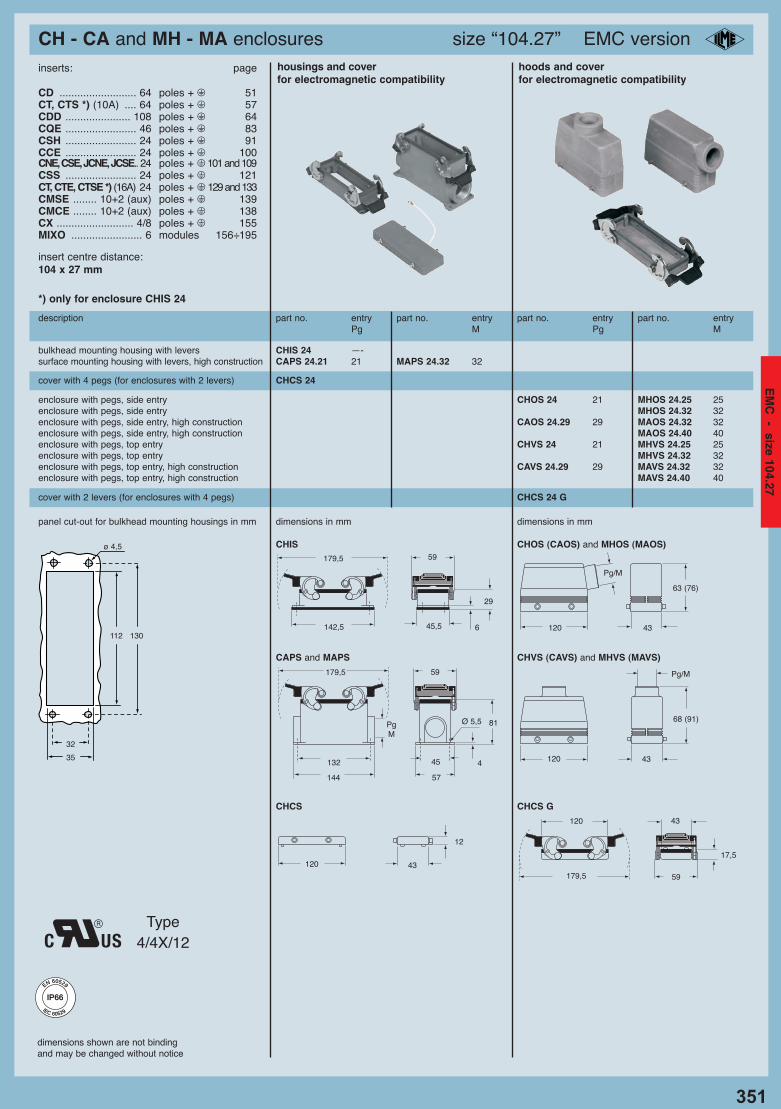
CH - CA and MH - MA enclosures size “104.27” EMC version
dimensions shown are not bindingand may be changed without notice
description part no. entry part no. entry part no. entry part no. entryPg M Pg M
housings and cover hoods and coverfor electromagnetic compatibility for electromagnetic compatibility
bulkhead mounting housing with levers CHIS 24 —-surface mounting housing with levers, high construction CAPS 24.21 21 MAPS 24.32 32
panel cut-out for bulkhead mounting housings in mm dimensions in mm dimensions in mm
CHIS CHOS (CAOS) and MHOS (MAOS)
CAPS and MAPS CHVS (CAVS) and MHVS (MAVS)
CHCS CHCS G
enclosure with pegs, side entry CHOS 24 21 MHOS 24.25 25enclosure with pegs, side entry MHOS 24.32 32enclosure with pegs, side entry, high construction CAOS 24.29 29 MAOS 24.32 32enclosure with pegs, side entry, high construction MAOS 24.40 40enclosure with pegs, top entry CHVS 24 21 MHVS 24.25 25enclosure with pegs, top entry MHVS 24.32 32enclosure with pegs, top entry, high construction CAVS 24.29 29 MAVS 24.32 32enclosure with pegs, top entry, high construction MAVS 24.40 40
cover with 4 pegs (for enclosures with 2 levers) CHCS 24
cover with 2 levers (for enclosures with 4 pegs) CHCS 24 G
112 130
32
35
ø 4,5
142,5
59
45,5 6
29
179,5
132
144
PgM
45
57
4
81Ø 5,5
59179,5
inserts: page
CD .......................... 64 poles + m 51CT, CTS *) (10A) .... 64 poles + m 57CDD ...................... 108 poles + m 64CQE ........................ 46 poles + m 83CSH ........................ 24 poles + m 91CCE ........................ 24 poles + m 100CNE, CSE, JCNE, JCSE.. 24 poles + m 101 and 109CSS ........................ 24 poles + m 121CT, CTE, CTSE *) (16A) 24 poles + m 129 and 133CMSE ........ 10+2 (aux) poles + m 139CMCE ........ 10+2 (aux) poles + m 138CX .......................... 4/8 poles + m 155MIXO ........................ 6 modules 156÷195
insert centre distance: 104 x 27 mm
*) only for enclosure CHIS 24
12
120 4317,5
120 43
179,5 59
Pg/M
43120
68 (91)
Type 4/4X/12
Pg/M
43120
63 (76)
351
IP66IP66
EN 60529
IEC 60529
EM
C - size 104.27
10_Custodie EMC_GB 335-351_Custodie_EMC_GB 08/11/11 14.39 Pagina 351