Embedded sysyetm components
37
EMBEDDED SYSTEM COMPONENTS BY - NAVEEN LAMBA
-
Upload
lambanaveen -
Category
Devices & Hardware
-
view
19 -
download
0
Transcript of Embedded sysyetm components

EMBEDDED SYSTEM COMPONENTS
BY - NAVEEN LAMBA
• Introduction
• Hardware Components
• Firmware Components
• RTOS System Software Mechanisms
• Software Application Components
• Summary
CONTENTS

INTRODUCTION
• System design can be approached in a bottom-up or a top-down fashion.
• Bottom-up approach: consists of determining fundamental components that go into a system.
• Top-down approach: hierarchical breakdown of the system into subsystems and then into components, example : concrete breakdown system.
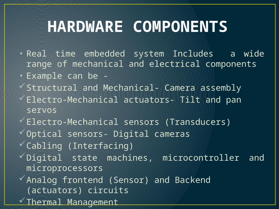
HARDWARE COMPONENTS
• Real time embedded system Includes a wide range of mechanical and electrical components
• Example can be -Structural and Mechanical- Camera assemblyElectro-Mechanical actuators- Tilt and pan servosElectro-Mechanical sensors (Transducers)Optical sensors- Digital camerasCabling (Interfacing)Digital state machines, microcontroller and
microprocessorsAnalog frontend (Sensor) and Backend (actuators)
circuitsThermal Management
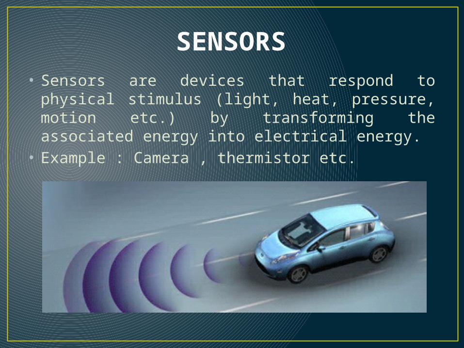
SENSORS• Sensors are devices that respond to physical
stimulus (light, heat, pressure, motion etc.) by transforming the associated energy into electrical energy.
• Example : Camera , thermistor etc.
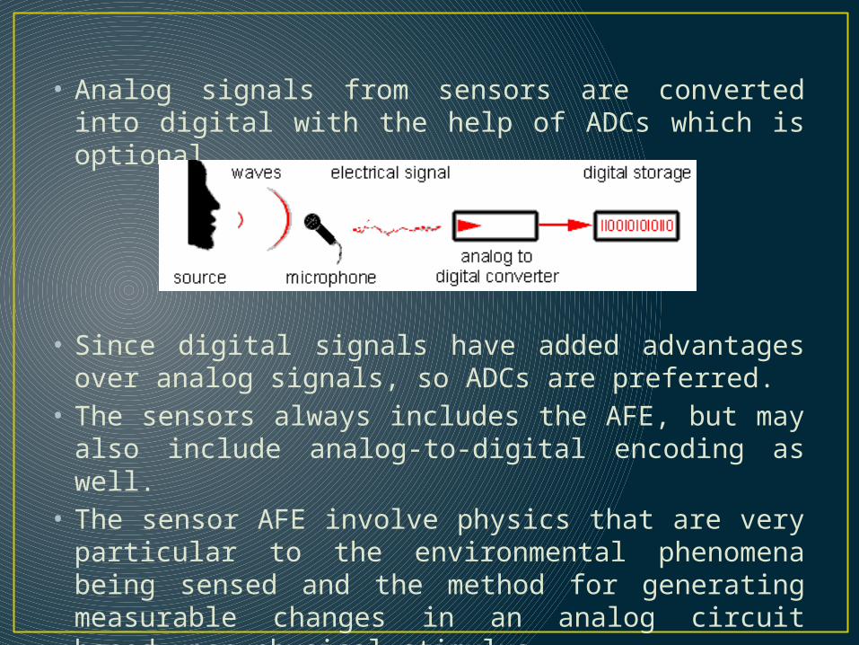
• Analog signals from sensors are converted into digital with the help of ADCs which is optional.
• Since digital signals have added advantages over analog signals, so ADCs are preferred.
• The sensors always includes the AFE, but may also include analog-to-digital encoding as well.
• The sensor AFE involve physics that are very particular to the environmental phenomena being sensed and the method for generating measurable changes in an analog circuit based upon physical stimulus.

• The ADC implementation has significant impact on the encoding capability, including the following:
i. Sampling frequency ii. Sample accuracyiii. Input range
• ADC requires a reference voltage and normally ADC encodes all the inputs into a range of values from zero to vref/(2n), where vref is the reference voltage.
• The resolution can clearly be increased by reducing the reference voltage ,however, this is at the cost of constraining the input range.
• This tradeoff drives the selection of how many bits the ADC provides in the encoding.
• Speed of sampling AFE depends upon type of ADC which are-
i. Flash: Using comparators, 1 per voltage step, and resistors
ii. Successive approximation: Comparators and counting logic.
• The flash ADC conversion speed is the sum of the comparator delays and logic delay.
• The successive approximation ADC uses comparators to determine first whether the input is greater than half the reference, then to determine whether it is greater than one quarter, and so on until the LSB comparison is made and the signal level has been approximated successively to the bit accuracy of the ADC.
• Typically, Flash ADC are the fastest variety.
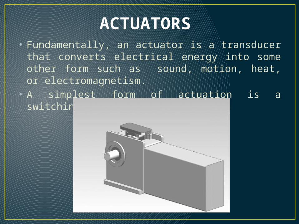
ACTUATORS• Fundamentally, an actuator is a transducer that
converts electrical energy into some other form such as sound, motion, heat, or electromagnetism.
• A simplest form of actuation is a switching.
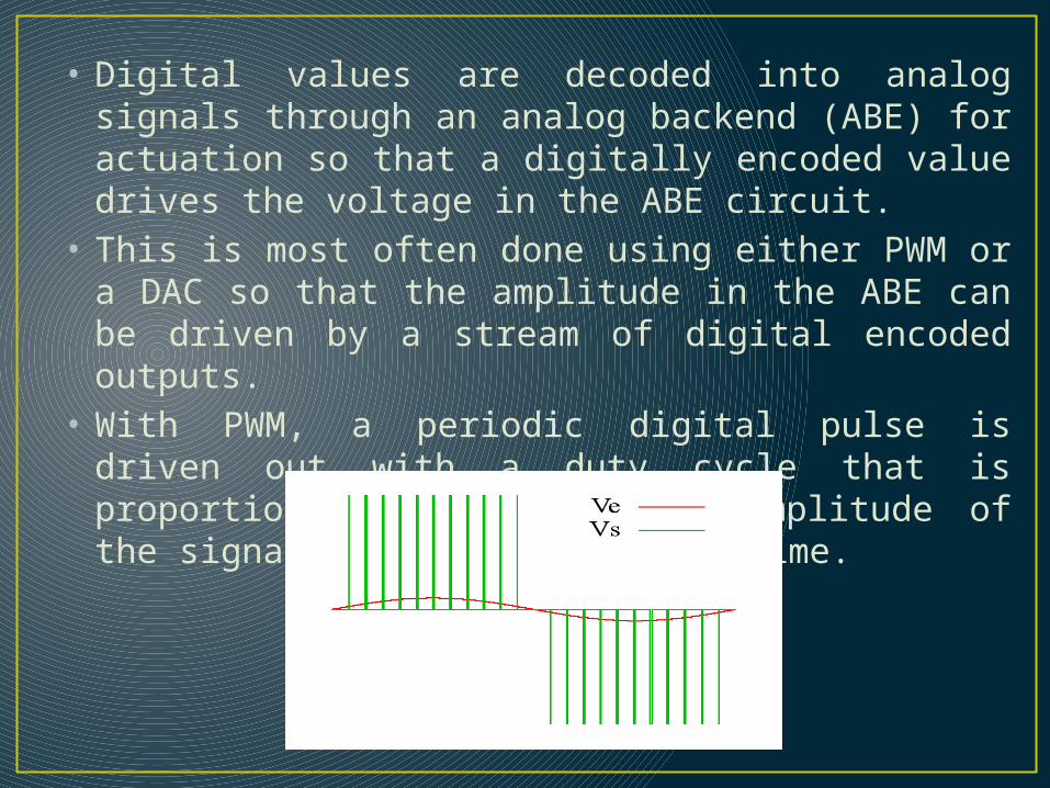
• Digital values are decoded into analog signals through an analog backend (ABE) for actuation so that a digitally encoded value drives the voltage in the ABE circuit.
• This is most often done using either PWM or a DAC so that the amplitude in the ABE can be driven by a stream of digital encoded outputs.
• With PWM, a periodic digital pulse is driven out with a duty cycle that is proportional to the desired amplitude of the signal at a given point in time.
• The DAC provides the proportional output automatically based upon the last commanded, digital output rather than decoding using a digital duty cycle.
• DAC actuator interfaces should be characterized by -
i. Type of actuation- on/off or DAC/PWM modulatedii. Speed of actuationiii. Accuracy of modulation
• Most often for accurate high-rate actuators, a DAC is required rather than relays or PWM.
• Actuators can be very unstable and suffer over-shoot or failure to settle without careful design and potential feedback from sensors.

I/O interfaces
• The I/O, in general , to and from a real-time embedded system can be classified first as either analog or digital.
• In the case of analog I/O , an ADC is required to encode analog inputs and a DAC,PWM, or relay interface is required to decode digital outputs when analog I/O is interfaced to a real-time embedded system.
• So prior to ABE or after the AFE, the embedded system is simply sees a digital I/O.
I/O INTERFACES

• The form of the digital I/O can vary significantly and can be characterized as-
i. Word-at-a-time I/Oii. Block I/O
• In case of word I/O, a simple set of registers defines the interface to the AFE/ABE and provides status, data, and control for encode/decode.
• The word I/O interfaces require significant interaction with the real-time embedded system and are not very efficient but do provide simple low rate I/O interfaces.
• These interfaces require programmed I/O where a CPU is involved in each input and output for all phases of the read/write, status monitoring, and control.
• This is often not desirable for higher—rate interfaces where even powerful CPUs would spend way too many cycles on programmed I/O and not enough on processing to provide services.
• Most high rate interfaces have a block I/O interface where a State-machine or a DMA engine provides command and control of the word encoding/decoding and less frequently interrupts the CPU when significant large blocks of data have been encoded/decoded.
• The method of interfacing word or block I/O can be-i. MMIOii. Port I/O
• Processor cores traditionally have provided I/O through dedicated pins from the CPU to other devices called I/O ports. An alternative is to save on off-chip interface pins by mapping MMIO onto existing address and data lines in/ out of the CPU so that I/O causes devices to be read or written in the same address space as memory devices.
• Many processors, such as the Intel X86, provide both port I/O and MMIO.
• When devices are memory mapped, care must be taken to ensure that the MMU (Memory Management Unit) is aware that particular address ranges are being used for device I/O so that output data is not cached, writes are fully drained to the device rather than buffered, and the address range is allowed to be accessed without exception.
PROCESSOR COMPLEX• Almost all modern real-time embedded systems
include a general-purpose CPU to process firmware/ software to provide updatable and flexible services by processing and linking sensor inputs to actuator outputs. If the services that a real-time embedded system must provide are so well known that they can be fully committed to a hardware state machine, then perhaps a processor complex (or set of interconnected CPUs) is not needed. Most often, services are expected to change over time, are not well enough specified initially, or are too complex to consider hardware only implementations.
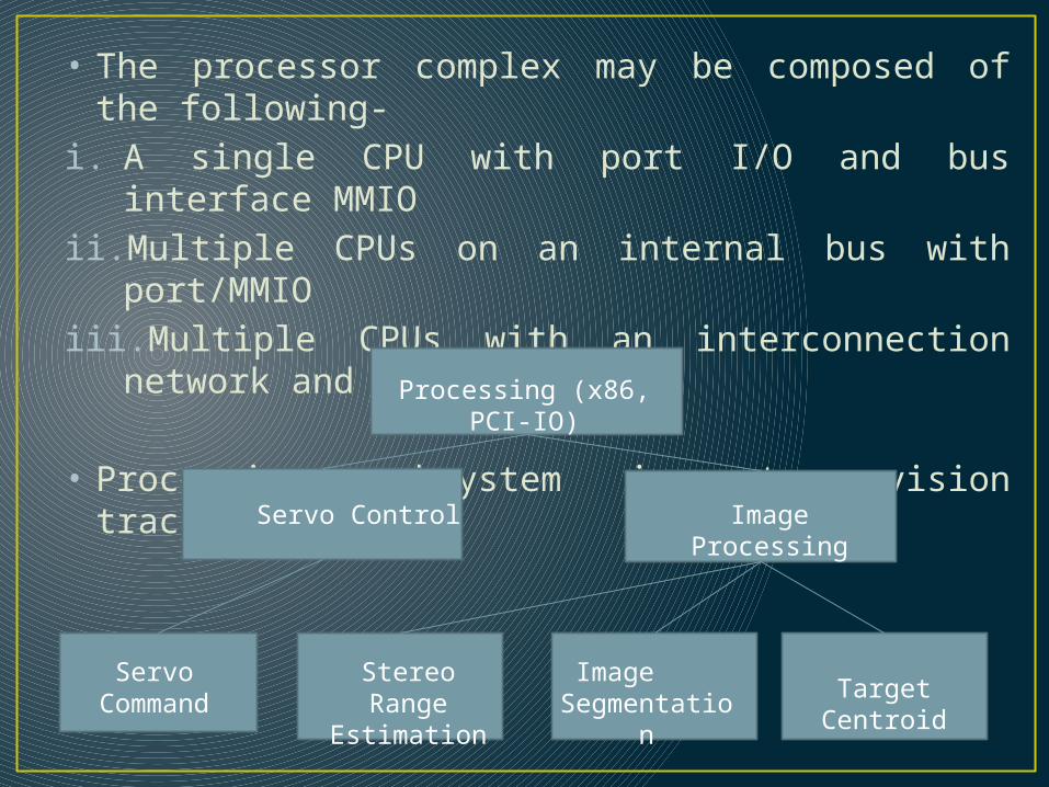
• The processor complex may be composed of the following-
i. A single CPU with port I/O and bus interface MMIOii. Multiple CPUs on an internal bus with port/MMIOiii. Multiple CPUs with an interconnection network
and port/MMIO
• Processing subsystem in stereo-vision tracking system
Processing (x86, PCI-IO)
Servo Control Image Processing
Servo Command
Stereo Range
Estimation
Image Segmentatio
n
Target Centroid

PROCESSOR AND I/O INTERCONNECTIONS
• For multi-CPU real-time embedded systems, an interconnection network is required to enable I/O and processing to be distributed.
• The interconnection network can bei. Simple bus or backplane(e.g., PCI or VME)ii. On-chip local bus with BIU to back plane I/O busiii. A cross-bar on-chip interconnection between
CPUsiv. An off-board network– e.g., firewire,USB,
Ethernet

Taxonomy of processor-I/O interconnection strategies

BUS INTERCONNECTION
• Many different bus architectures have been used and are being used for embedded systems.
• Here we are going to examine to two different buses namely VME(Versa Module Extension) bus and PCI bus.
• The VME bus has historically been popular and simple bus architecture used with embedded systems.
• By contrast, PCI is an emergent bus architecture that offers traditional parallel bus integration as well as high-speed serial interconnection with PCI Express.

COMPARISON OF PCI AND VME BUSES
Feature VME bus PCI 2.x bus
Bus transfers Asynchronous 20 MHz Synch clock 33/66 MHz
Target addressing 32,24, or 16 bit address Multiplexed 32/64 bit address/data bus
Data transfer 32,24, or 16 bit separate data bus
Multiplexed with 32 bit address bus
Data transfer types Word or block transfer limited to a specific block size(e.g. 512 bytes)
Burst transfer always with min and max length
Device interrupt mechanism
Daisy-chained prio interrupts
4 shared interrupt lines
Interrupt vectoring Interrupt data cycle following interrupt level
Map A-D onto processor vector
Bus access arbitration for multiple initiators
No arbitration, firmware or custom controller must ensure mutex access
Built-in hidden arbitration
Faster options VME-64+ PCI-X 1.0a; 2.0
HIGH-SPEED SERIAL INTERCONNECTION
• The high-speed serial interconnections are:i. Universal serial busii. Fire wireiii. PCI-Expressiv. Gigabit Ethernet
• Universal Serial Bus (USB) is an industry standard developed in the mid-1990s that defines the cables, connectors and communications protocols used in a bus for connection, communication, and power supply between computers and electronic devices.
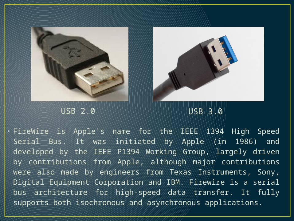
USB 2.0 USB 3.0
• FireWire is Apple's name for the IEEE 1394 High Speed Serial Bus. It was initiated by Apple (in 1986) and developed by the IEEE P1394 Working Group, largely driven by contributions from Apple, although major contributions were also made by engineers from Texas Instruments, Sony, Digital Equipment Corporation and IBM. Firewire is a serial bus architecture for high-speed data transfer. It fully supports both isochronous and asynchronous applications.
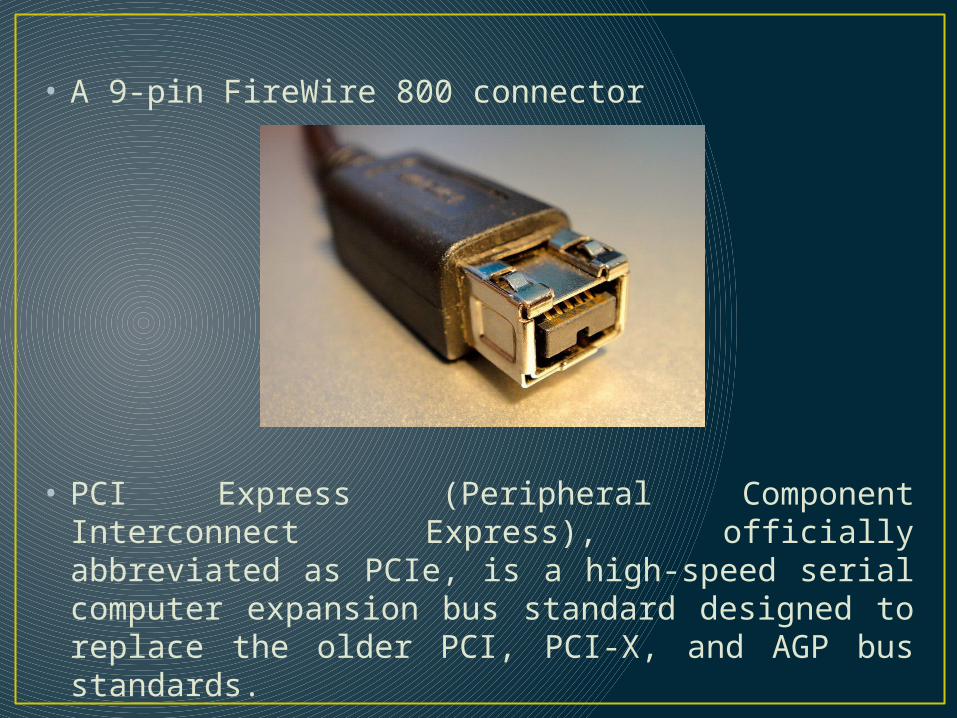
• A 9-pin FireWire 800 connector
• PCI Express (Peripheral Component Interconnect Express), officially abbreviated as PCIe, is a high-speed serial computer expansion bus standard designed to replace the older PCI, PCI-X, and AGP bus standards.

• PCIe has numerous improvements over the older standards, including higher maximum system bus throughput, lower I/O pin count and smaller physical footprint, better performance scaling for bus devices, a more detailed error detection and reporting mechanism (Advanced Error Reporting, AER), and native hot-plug functionality. More recent revisions of the PCIe standard provide hardware support for I/O virtualization.
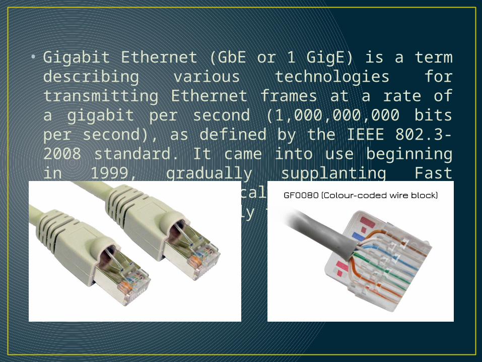
• Gigabit Ethernet (GbE or 1 GigE) is a term describing various technologies for transmitting Ethernet frames at a rate of a gigabit per second (1,000,000,000 bits per second), as defined by the IEEE 802.3-2008 standard. It came into use beginning in 1999, gradually supplanting Fast Ethernet in wired local networks, where it performed considerably faster.

LOW-SPEED SERIAL INTERCONNECTION
• Many real-time embedded systems not only include high-rate I/O for services such as video or network transport, but also include low-rate command/response or monitoring interfaces.
• If rate of transmission is not our high priority, then to decrease the cost of embedded system, we go for Low speed serial interconnection.
• The RS232, common serial, point-to-point data transmission has been used in real-time embedded systems since the advent of the industry and remains a common low-rate and debug interface.
• The RS232 link normally tops out around 115,200 bits/second (about 12KB/sec) and is not capable of long-distance transmission due to line noise at the 12-volt signalling levels it uses.
• The other options that are widely used are:i. RS422ii. Multidrop RS232,RS422iii. I2C (Inter IC)iv. SPI (Serial Peripheral Interface)
MEMORY SUBSYSTEMS
• Real-time embedded system require non-volatile data storage to boot the system and to start services.
• After a power-on reset, the processors in the processor complex each vector to a hardware-defined starting address to execute code.
• From a hardware view point, memory is better described as a hierarchy of storage devices
i. Registers (CPU and memory mapped for device control)
ii. Cacheiii. Working memoryiv. Extended memory

MEMORY MAP FOR AN EMBEDDED SYSTEM

FIRMWARE COMPONENTS• Some components can only be realized in hardware,
but many can be implemented with software or firmware (noting that software interfacing directly to hardware is typically called firmware).
• Furthermore, if the real—time embedded system has any software—based services or even Just management, firmware is needed to interface hardware resources to software applications.
Boot Code• The universal definition of firmware is code or
software that runs out of a nonvolatile device to make hardware resources available for the rest of the application software.
• Firmware providing this function is normally referred to in general as board support package (BSP) firmware because traditionally, this firmware has initialized and made available all onboard resources for a processor complex to software applications.
• Before the resources have been fully initialized, the firmware boots the board by executing code out of a nonvolatile device so that one or more basic interfaces is made operable and the system can now download additional application software.
• For example, the BSP boot firmware might initialize an Ethernet interface and provide TFTP download of application code for execution.

Boot Drivers• Device interface drivers are most often considered
firmware because they directly interface to hardware resources and make those resources available to higher level software applications.
• The architecture of a device driver interface is depicted in Figure on the next slide and includes both a HW bottom half interface and a SW top half interface.
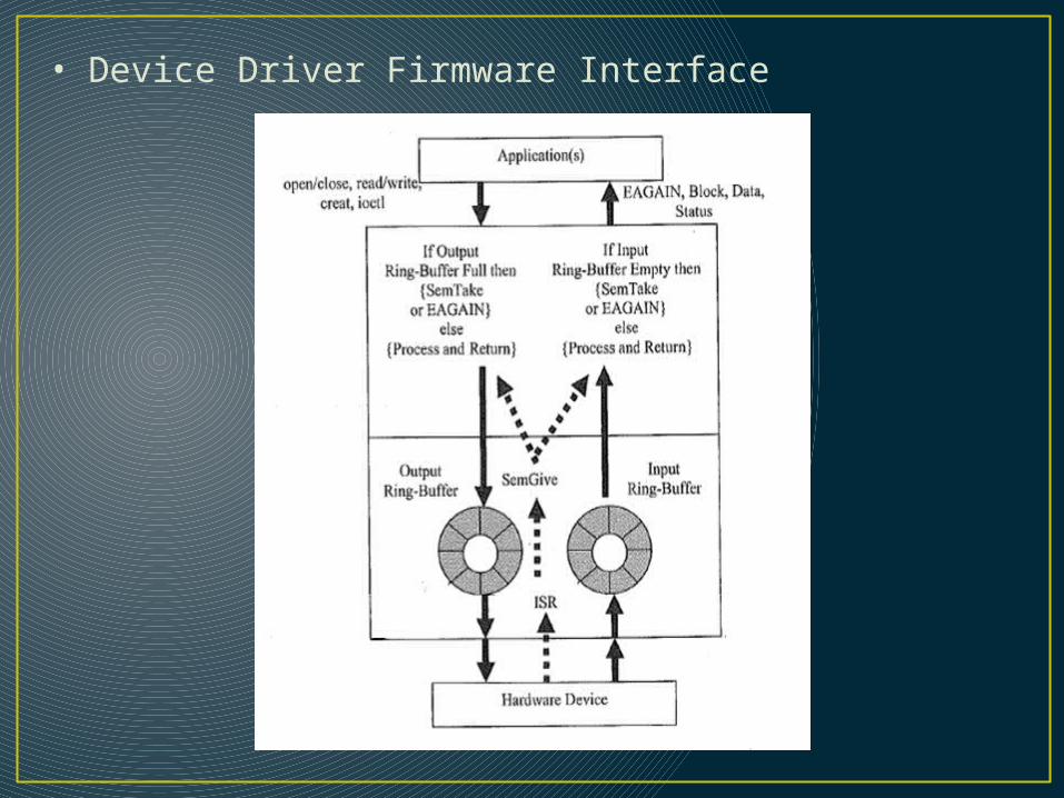
• Device Driver Firmware Interface
OS Services• Not all real-time embedded systems require an
operating system .• Most RTOS implementations do, however, provide a
layer of software that acts a single interface for all applications to gain access to system resources.
• Furthermore, most real-time systems incorporate an RTOS, which provides a framework for resource management and for scheduling processor resources with an RM policy. The RTOS also provides commonly needed services and libraries used by application services.
• The most fundamental services and mechanisms provided include the following:1. Priority preemptive scheduler for threads2. Thread control block management3. Inter-thread synchronization and communication (e.g., semaphores and message queues)
4. Basic I/O for system debug and Bring Up (eg., serial, Ethernet, LED.)5. ISR ( Interrupt Service Routine) installation on Interrupt vectors.6. Transition from boot to operational state.7. Timers for delays and blocked thread timeouts. 8. Drivers for basic hardware devices (serial, Ethernet, timers, nonvolatile memory)
Extended services beyond these may be provided to assist development and debug of a system:
1. Cross debug agent.2. Interactive shell to view control blocks and system context.3. Capability to dynamically load and execute code object files.4. Interface to resource analysis tools (e.g., WindView).


![Developing Reusable Software Components for Embedded Systemsltahvild/courses/... · July 13, 2009 Components for Embedded Systems 28 References Cont’d [10] Severine Sentilles, Anders](https://static.fdocuments.in/doc/165x107/606be4a9ba084a3b6955bdba/developing-reusable-software-components-for-embedded-systems-ltahvildcourses.jpg)