EMA 3702 Mechanics & Materials Science (Mechanics of Materials)€¦ · · 2018-04-09From chapter...
28
EMA 3702 Mechanics & Materials Science (Mechanics of Materials) Chapter 10 Columns
Transcript of EMA 3702 Mechanics & Materials Science (Mechanics of Materials)€¦ · · 2018-04-09From chapter...
EMA 3702
Mechanics & Materials Science
(Mechanics of Materials)
Chapter 10 Columns
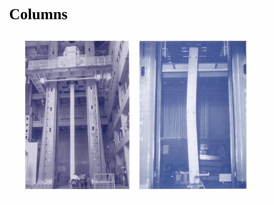
Columns
Introduction
Columns are vertical prismatic members subjected to
compressive forces
Goals:
1. Study the stability of columns: resistance to buckling
under axial loadings
2. Determine critical load, stress, and/or column
dimension information (length/cross-section area)
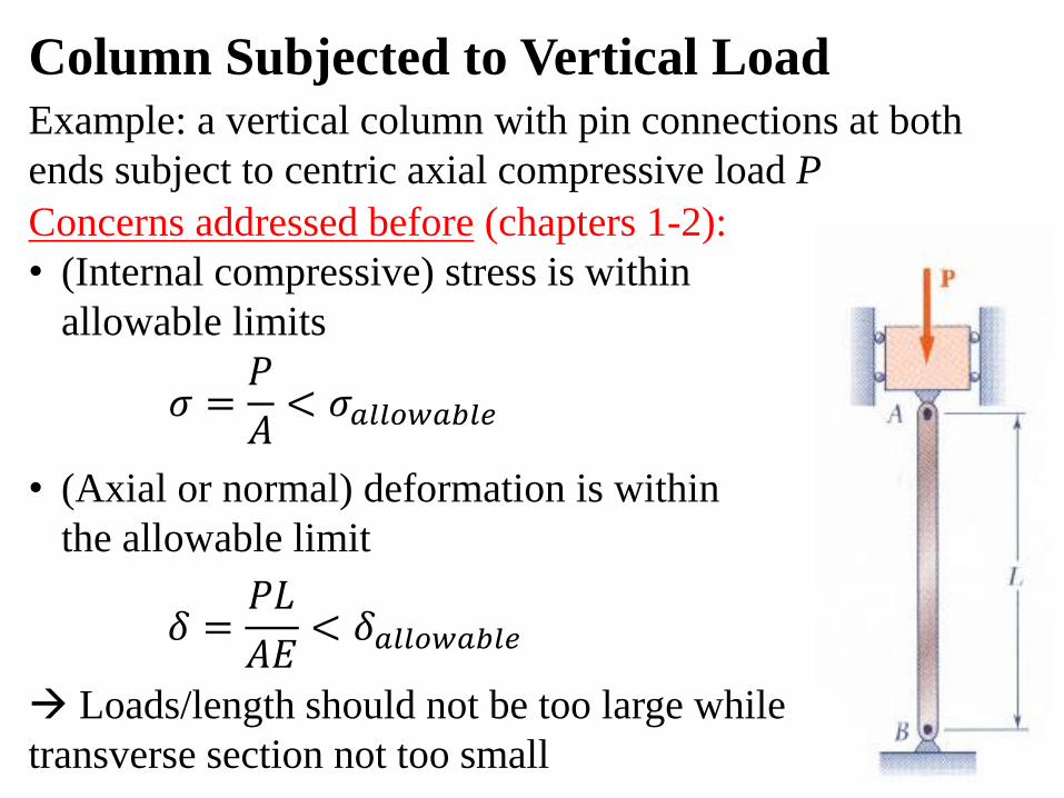
Column Subjected to Vertical Load
Example: a vertical column with pin connections at both
ends subject to centric axial compressive load P
Concerns addressed before (chapters 1-2):
• (Internal compressive) stress is within
allowable limits
• (Axial or normal) deformation is within
the allowable limit
Loads/length should not be too large while
transverse section not too small
𝜎 =𝑃
𝐴< 𝜎𝑎𝑙𝑙𝑜𝑤𝑎𝑏𝑙𝑒
𝛿 =𝑃𝐿
𝐴𝐸< 𝛿𝑎𝑙𝑙𝑜𝑤𝑎𝑏𝑙𝑒
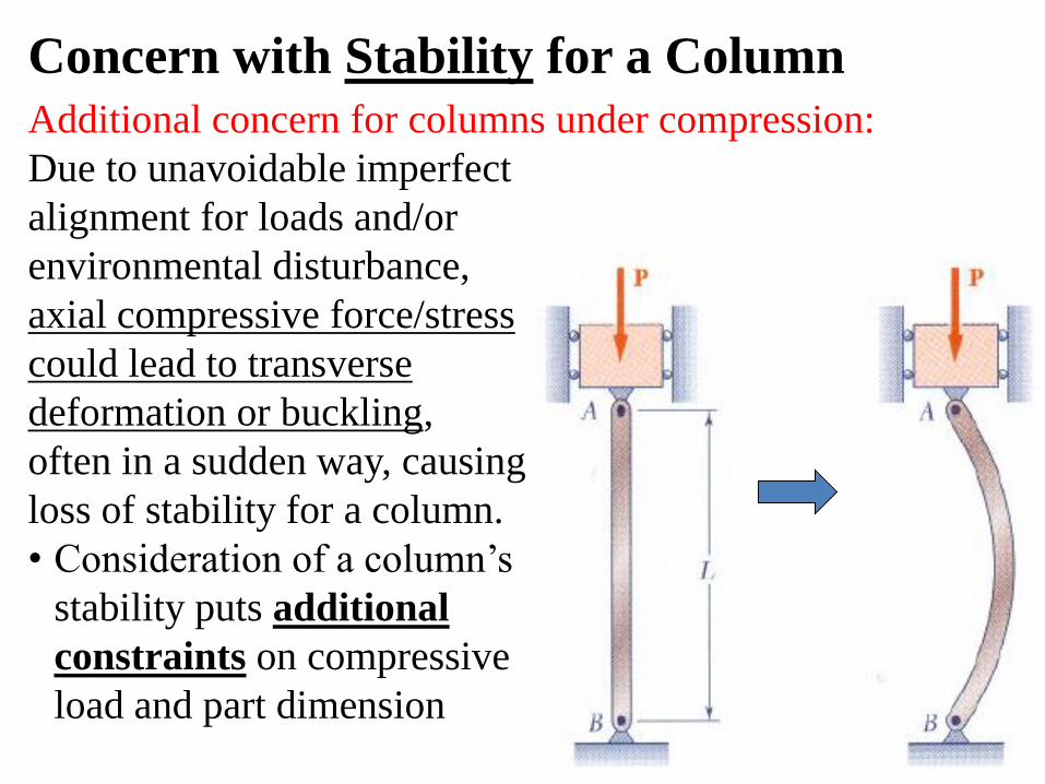
Concern with Stability for a Column
Additional concern for columns under compression:
Due to unavoidable imperfect
alignment for loads and/or
environmental disturbance,
axial compressive force/stress
could lead to transverse
deformation or buckling,
often in a sudden way, causing
loss of stability for a column.
• Consideration of a column’s
stability puts additional
constraints on compressive
load and part dimension
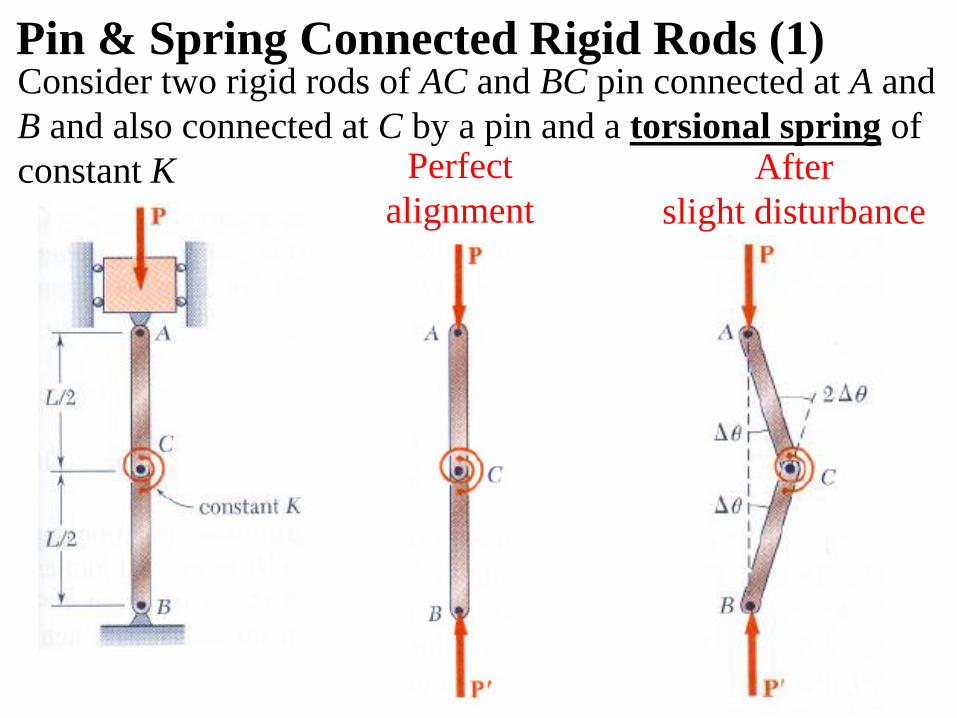
Pin & Spring Connected Rigid Rods (1)Consider two rigid rods of AC and BC pin connected at A and
B and also connected at C by a pin and a torsional spring of
constant K Perfect
alignment
After
slight disturbance
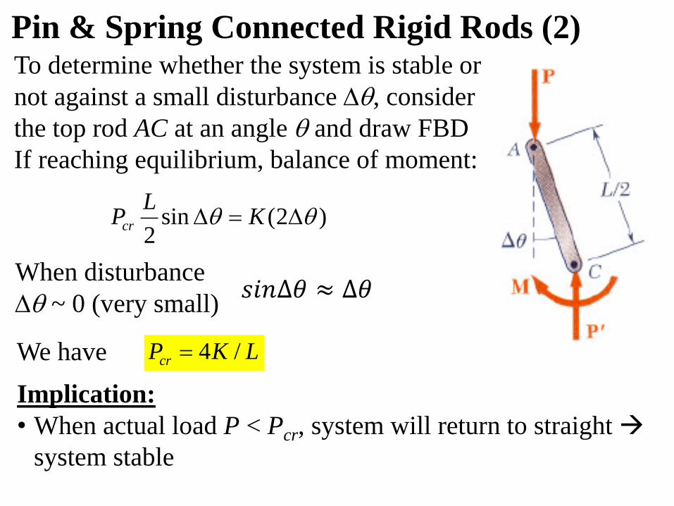
Implication:
• When actual load P < Pcr, system will return to straight
system stable
To determine whether the system is stable or
not against a small disturbance , consider
the top rod AC at an angle and draw FBD
If reaching equilibrium, balance of moment:
We have
Pin & Spring Connected Rigid Rods (2)
When disturbance
~ 0 (very small)
)2(sin2
KL
Pcr
LKPcr /4
𝑠𝑖𝑛∆𝜃 ≈ ∆𝜃
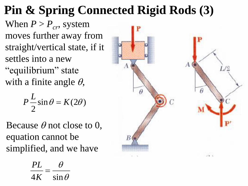
When P > Pcr, system
moves further away from
straight/vertical state, if it
settles into a new
“equilibrium” state
with a finite angle ,
Because not close to 0,
equation cannot be
simplified, and we have
Pin & Spring Connected Rigid Rods (3)
)2(sin2
KL
P
sin4
K
PL
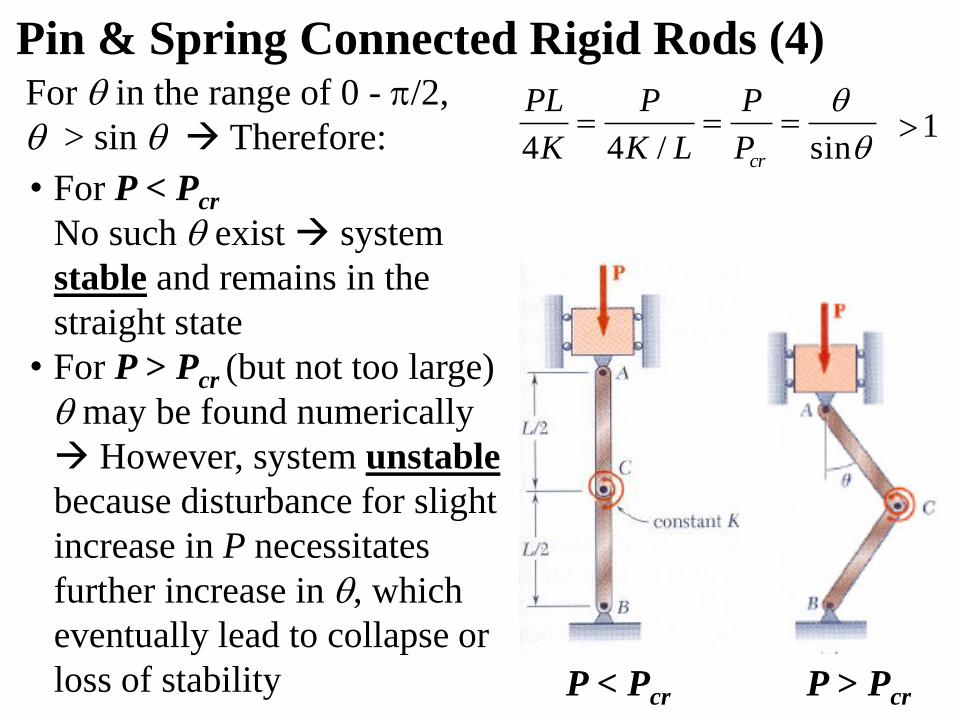
For in the range of 0 - /2,
> sin Therefore:
• For P < Pcr
No such exist system
stable and remains in the
straight state
• For P > Pcr (but not too large)
may be found numerically
However, system unstable
because disturbance for slight
increase in P necessitates
further increase in , which
eventually lead to collapse or
loss of stability
Pin & Spring Connected Rigid Rods (4)
P < Pcr P > Pcr
1
sin/44
crP
P
LK
P
K
PL
Euler’s Formula for Pin-Ended Columns (1)
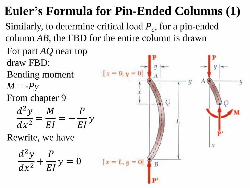
Similarly, to determine critical load Pcr for a pin-ended
column AB, the FBD for the entire column is drawn
For part AQ near top
draw FBD:
Bending moment
M = -Py
From chapter 9
Rewrite, we have
𝑑2𝑦
𝑑𝑥2=𝑀
𝐸𝐼= −
𝑃
𝐸𝐼𝑦
𝑑2𝑦
𝑑𝑥2+𝑃
𝐸𝐼𝑦 = 0
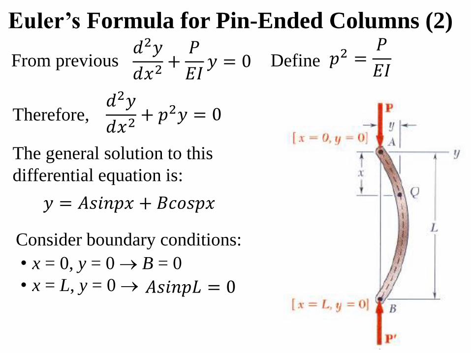
Define
The general solution to this
differential equation is:
Consider boundary conditions:
• x = 0, y = 0 B = 0
• x = L, y = 0
Euler’s Formula for Pin-Ended Columns (2)
Therefore,
From previous𝑑2𝑦
𝑑𝑥2+𝑃
𝐸𝐼𝑦 = 0 𝑝2 =
𝑃
𝐸𝐼
𝑑2𝑦
𝑑𝑥2+ 𝑝2𝑦 = 0
𝑦 = 𝐴𝑠𝑖𝑛𝑝𝑥 + 𝐵𝑐𝑜𝑠𝑝𝑥
𝐴𝑠𝑖𝑛𝑝𝐿 = 0
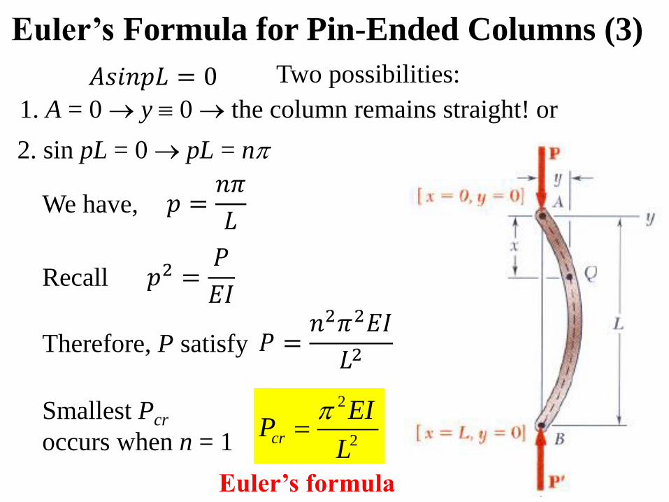
1. A = 0 y 0 the column remains straight! or
2. sin pL = 0 pL = n
Recall
Therefore, P satisfy
Smallest Pcr
occurs when n = 1
Euler’s formula
Euler’s Formula for Pin-Ended Columns (3)
Two possibilities:
2
2
L
EIPcr
We have,
𝐴𝑠𝑖𝑛𝑝𝐿 = 0
𝑝 =𝑛𝜋
𝐿
𝑝2 =𝑃
𝐸𝐼
𝑃 =𝑛2𝜋2𝐸𝐼
𝐿2
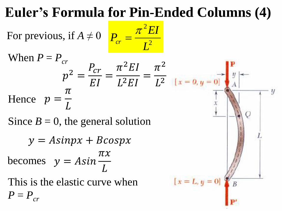
For previous, if A ≠ 0
When P = Pcr
Hence
This is the elastic curve when
P = Pcr
Euler’s Formula for Pin-Ended Columns (4)
2
2
L
EIPcr
Since B = 0, the general solution
becomes
𝑝2 =𝑃𝑐𝑟𝐸𝐼
=𝜋2𝐸𝐼
𝐿2𝐸𝐼=𝜋2
𝐿2
𝑝 =𝜋
𝐿
𝑦 = 𝐴𝑠𝑖𝑛𝑝𝑥 + 𝐵𝑐𝑜𝑠𝑝𝑥
𝑦 = 𝐴𝑠𝑖𝑛𝜋𝑥
𝐿
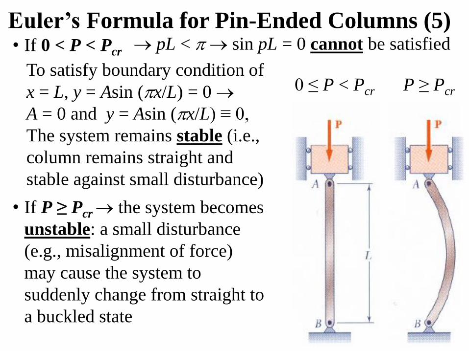
• If 0 < P < Pcr
Euler’s Formula for Pin-Ended Columns (5)
To satisfy boundary condition of
x = L, y = Asin (x/L) = 0
A = 0 and y = Asin (x/L) ≡ 0,
The system remains stable (i.e.,
column remains straight and
stable against small disturbance)
• If P ≥ Pcr the system becomes
unstable: a small disturbance
(e.g., misalignment of force)
may cause the system to
suddenly change from straight to
a buckled state
0 ≤ P < Pcr P ≥ Pcr
pL < sin pL = 0 cannot be satisfied
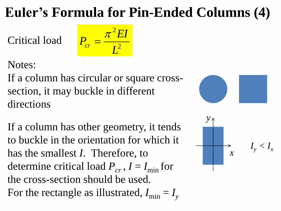
Critical load
Euler’s Formula for Pin-Ended Columns (4)
2
2
L
EIPcr
Notes:
If a column has circular or square cross-
section, it may buckle in different
directions
If a column has other geometry, it tends
to buckle in the orientation for which it
has the smallest I. Therefore, to
determine critical load Pcr , I = Imin for
the cross-section should be used.
For the rectangle as illustrated, Imin = Iy
x
y
Iy < Ix
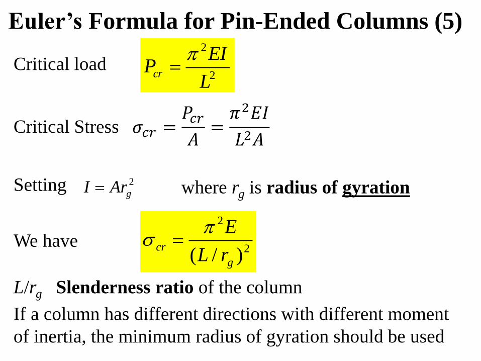
Critical load
Setting where rg is radius of gyration
L/rg Slenderness ratio of the column
Euler’s Formula for Pin-Ended Columns (5)
2
2
L
EIPcr
Critical Stress
2
2
)/( g
crrL
E We have
If a column has different directions with different moment
of inertia, the minimum radius of gyration should be used
2
gArI
𝜎𝑐𝑟 =𝑃𝑐𝑟𝐴
=𝜋2𝐸𝐼
𝐿2𝐴
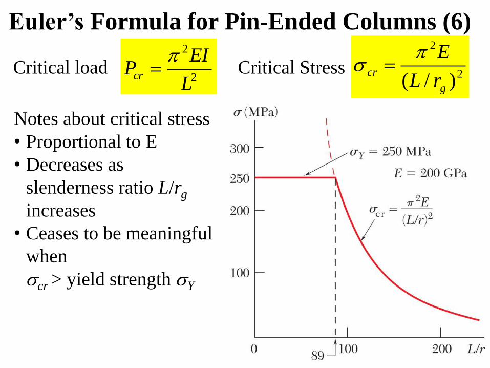
Critical load
Euler’s Formula for Pin-Ended Columns (6)
2
2
L
EIPcr
Critical Stress 2
2
)/( g
crrL
E
Notes about critical stress
• Proportional to E
• Decreases as
slenderness ratio L/rg
increases
• Ceases to be meaningful
when
cr > yield strength Y
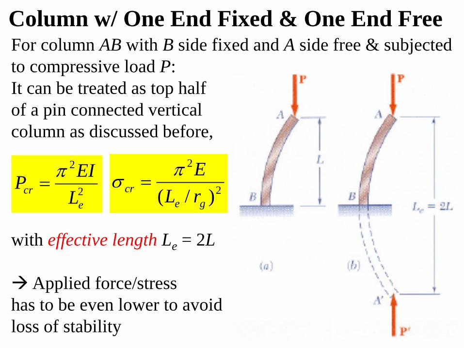
Column w/ One End Fixed & One End FreeFor column AB with B side fixed and A side free & subjected
to compressive load P:
It can be treated as top half
of a pin connected vertical
column as discussed before,
with effective length Le = 2L
Applied force/stress
has to be even lower to avoid
loss of stability
2
2
e
crL
EIP
2
2
)/( ge
crrL
E
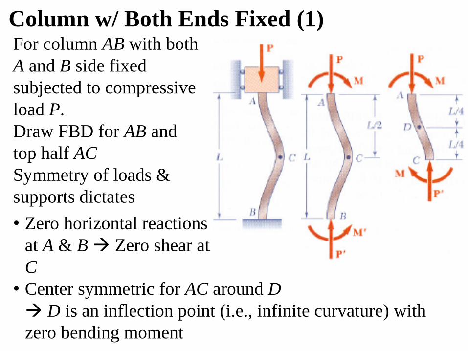
Column w/ Both Ends Fixed (1)For column AB with both
A and B side fixed
subjected to compressive
load P.
Draw FBD for AB and
top half AC
Symmetry of loads &
supports dictates
• Zero horizontal reactions
at A & B Zero shear at
C
• Center symmetric for AC around D
D is an inflection point (i.e., infinite curvature) with
zero bending moment
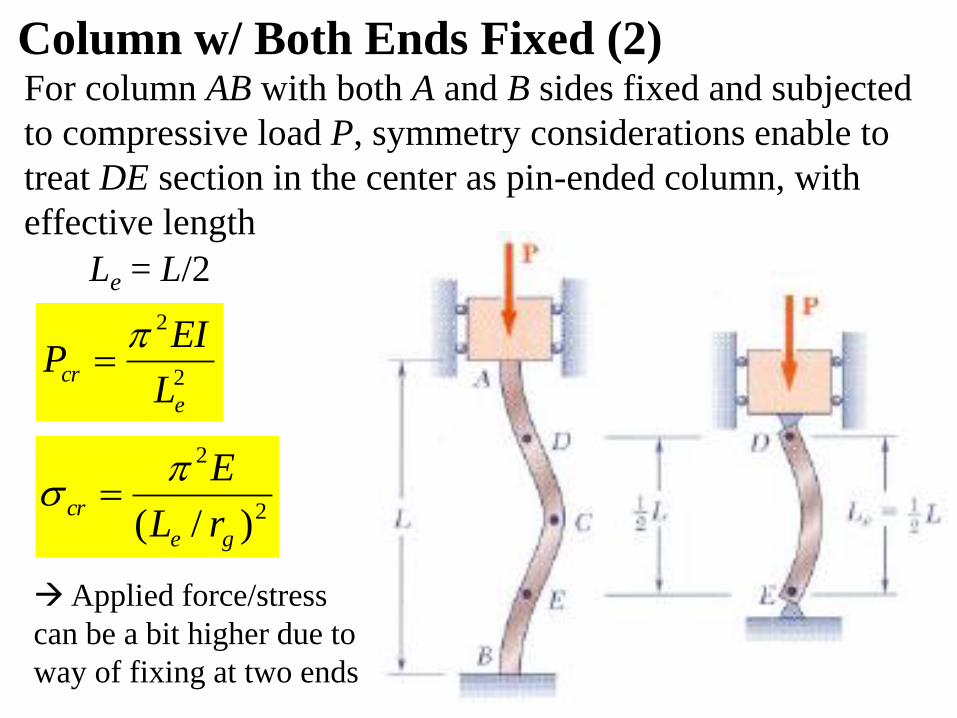
Le = L/2
Column w/ Both Ends Fixed (2)For column AB with both A and B sides fixed and subjected
to compressive load P, symmetry considerations enable to
treat DE section in the center as pin-ended column, with
effective length
2
2
e
crL
EIP
2
2
)/( ge
crrL
E
Applied force/stress
can be a bit higher due to
way of fixing at two ends
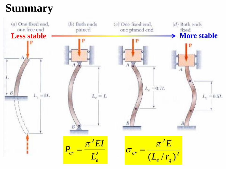
Summary
2
2
e
crL
EIP
2
2
)/( ge
crrL
E
More stableLess stable
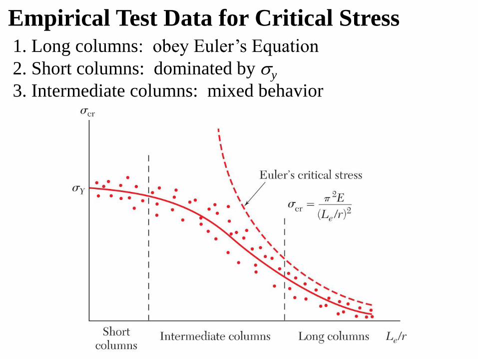
1. Long columns: obey Euler’s Equation
2. Short columns: dominated by y
3. Intermediate columns: mixed behavior
Empirical Test Data for Critical Stress
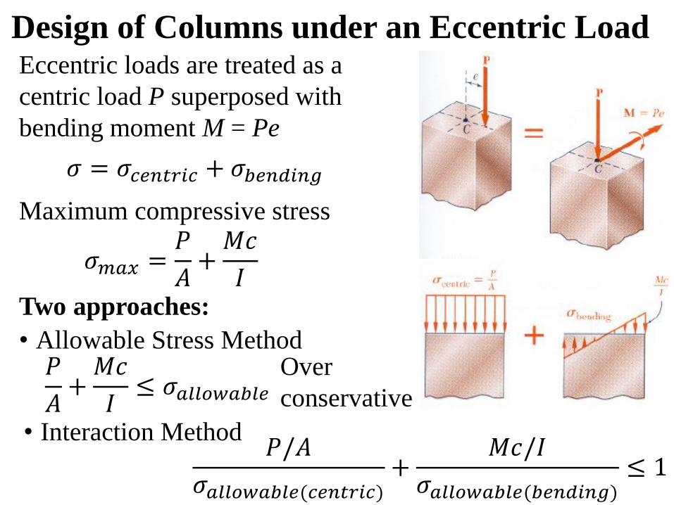
Design of Columns under an Eccentric Load
Two approaches:
Eccentric loads are treated as a
centric load P superposed with
bending moment M = Pe
Maximum compressive stress
• Allowable Stress Method
• Interaction Method
Over
conservative
𝜎 = 𝜎𝑐𝑒𝑛𝑡𝑟𝑖𝑐 + 𝜎𝑏𝑒𝑛𝑑𝑖𝑛𝑔
𝜎𝑚𝑎𝑥 =𝑃
𝐴+𝑀𝑐
𝐼
𝑃
𝐴+𝑀𝑐
𝐼≤ 𝜎𝑎𝑙𝑙𝑜𝑤𝑎𝑏𝑙𝑒
𝑃/𝐴
𝜎𝑎𝑙𝑙𝑜𝑤𝑎𝑏𝑙𝑒(𝑐𝑒𝑛𝑡𝑟𝑖𝑐)+
𝑀𝑐/𝐼
𝜎𝑎𝑙𝑙𝑜𝑤𝑎𝑏𝑙𝑒(𝑏𝑒𝑛𝑑𝑖𝑛𝑔)≤ 1
EMA 3702 Mechanics & Materials Science Zhe Cheng (2018) 1 Introduction
Homework 10.0
Read section 10.1, 10.3 and 10.4 and give a statement confirm
the reading
EMA 3702 Mechanics & Materials Science Zhe Cheng (2018) 1 Introduction
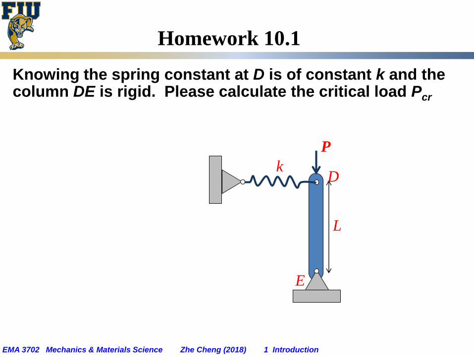
Homework 10.1
Knowing the spring constant at D is of constant k and the column DE is rigid. Please calculate the critical load Pcr
E
L
Dk
P
EMA 3702 Mechanics & Materials Science Zhe Cheng (2018) 1 Introduction
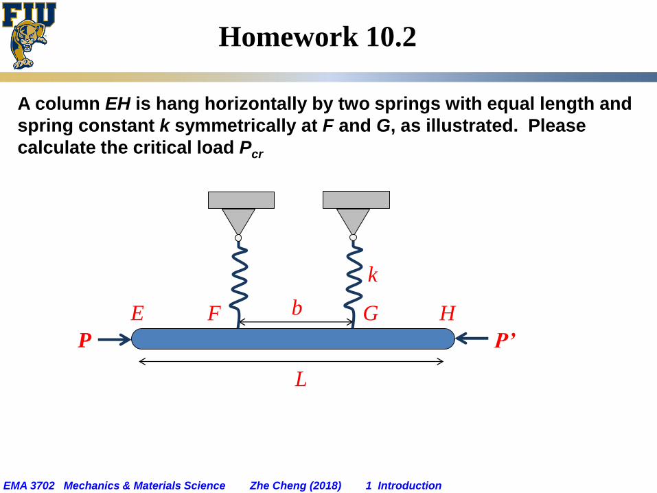
Homework 10.2
A column EH is hang horizontally by two springs with equal length and
spring constant k symmetrically at F and G, as illustrated. Please
calculate the critical load Pcr
E
k
P’P
F G Hb
L
EMA 3702 Mechanics & Materials Science Zhe Cheng (2018) 1 Introduction
Homework 10.3
A long cylinder shaped solid column has length L and outside
diameter (OD) d. It is made of a material with elastic modulus E. If a
separate cylinder-shaped hollow column is to be made with the same
material and same length L and O.D. d, but has inner diameter of 0.5d,
please calculate (a) the saving in weight for the hollow column versus
the original solid column, and (b) the relative reduction in critical load
for the hollow column versus the original solid cylinder.
EMA 3702 Mechanics & Materials Science Zhe Cheng (2018) 1 Introduction
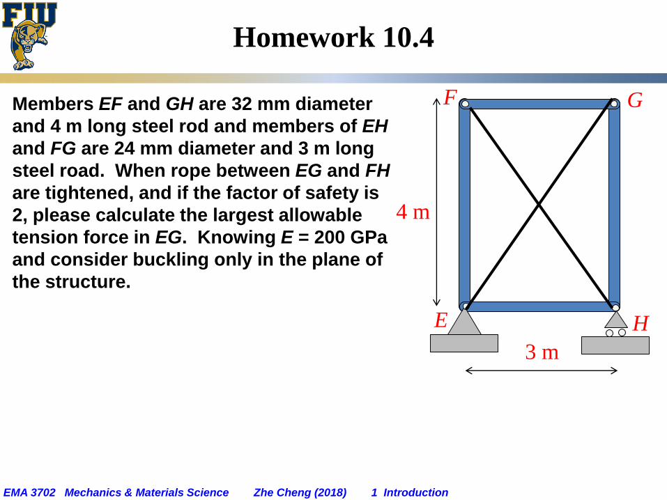
Homework 10.4
Members EF and GH are 32 mm diameter
and 4 m long steel rod and members of EH
and FG are 24 mm diameter and 3 m long
steel road. When rope between EG and FH
are tightened, and if the factor of safety is
2, please calculate the largest allowable
tension force in EG. Knowing E = 200 GPa
and consider buckling only in the plane of
the structure.
E H
F G
4 m
3 m