Eliminator Shaft Mount Reducer - WorldWide Electric
21
03.18.2022 Installation and Maintenance Manual - “Eliminator” Series Shaft Mount WorldWide Electric Corporation Phone: 1-800-808-2131 Fax: 1-800-711-1616 Website: www.worldwideelectric.net WorldWide Electric Corporation Reducer
Transcript of Eliminator Shaft Mount Reducer - WorldWide Electric

03.18.2022
Installation and Maintenance Manual
- “Eliminator” Series Shaft Mount
WorldWide Electric Corporation Phone: 1-800-808-2131
Fax: 1-800-711-1616 Website: www.worldwideelectric.net
WorldWide Electric Corporation Reducer
03.18.2022
WARNING: Because of the possible danger to person(s) or property from accidents which may result from improper use of products, it is important that correct procedures be followed. Products must be used in accordance with the engineering information specified in the WorldWide Electric Corporation Gear Reducers Stock Products catalog. Proper installation, maintenance and operation procedures must be observed. The instructions in this installation and maintenance manual must be followed. Inspections should be made as necessary to assure safe operation under prevailing conditions. Proper guards and other suitable safety devices or procedures, as may be desirable, or as may be specified in safety codes should be provided, and are neither provided by WorldWide Electric Corporation, nor the responsibility of WorldWide Electric Corporation. This unit and its associated equipment must be installed, adjusted and maintained by qualified personnel who are familiar with the construction and operation of all equipment in the system and the potential hazards involved. When risks to persons or property may be involved, a holding device must be an integral part of the driven equipment beyond the speed reducer output shaft.
Contents
Installation ....................................................................................................................................................................... 3
Lubrication Schedule ....................................................................................................................................................... 5
Replacement of Parts ...................................................................................................................................................... 6
Motor Mount Installation .............................................................................................................................................. 10
Backstop Installation ..................................................................................................................................................... 11
Backstop Description ............................................................................................................................................. 11
Prior to Installation ................................................................................................................................................ 11
Installation ............................................................................................................................................................. 12
After Installation .................................................................................................................................................... 14
Dismantling ............................................................................................................................................................ 14
Lubrication and Maintenance of the Backstop Assembly ..................................................................................... 14
Backstop Assembly Type and Rotation Illustration ............................................................................................... 14
Backstop Dimensions............................................................................................................................................. 15
SCSMR Accessories ........................................................................................................................................................ 16
Screw Conveyor Drive Components ...................................................................................................................... 16
Screw Conveyor Accessories Assembly ................................................................................................................. 16
Screw Conveyor Flange Adapters .......................................................................................................................... 17
Screw Conveyor Drive Shafts ................................................................................................................................. 18
Guidelines for Long-term Storage ................................................................................................................................. 19
SCSMR Exploded View ................................................................................................................................................... 20
SCSMR Ratio/ Speed Table ............................................................................................................................................ 20
Limited Warranty ........................................................................................................................................................... 21
3
Note: Satisfactory performance depends on proper installation, lubrication and maintenance. Therefore, it is important that the instructions in this manual are followed carefully.
WARNING: To ensure that the drive is not unexpectedly started, turn off and lock out or tag the power source before proceeding. Remove all external loads from drive before removing or servicing reducer or accessories. Failure to observe these precautions could result in bodily injury.
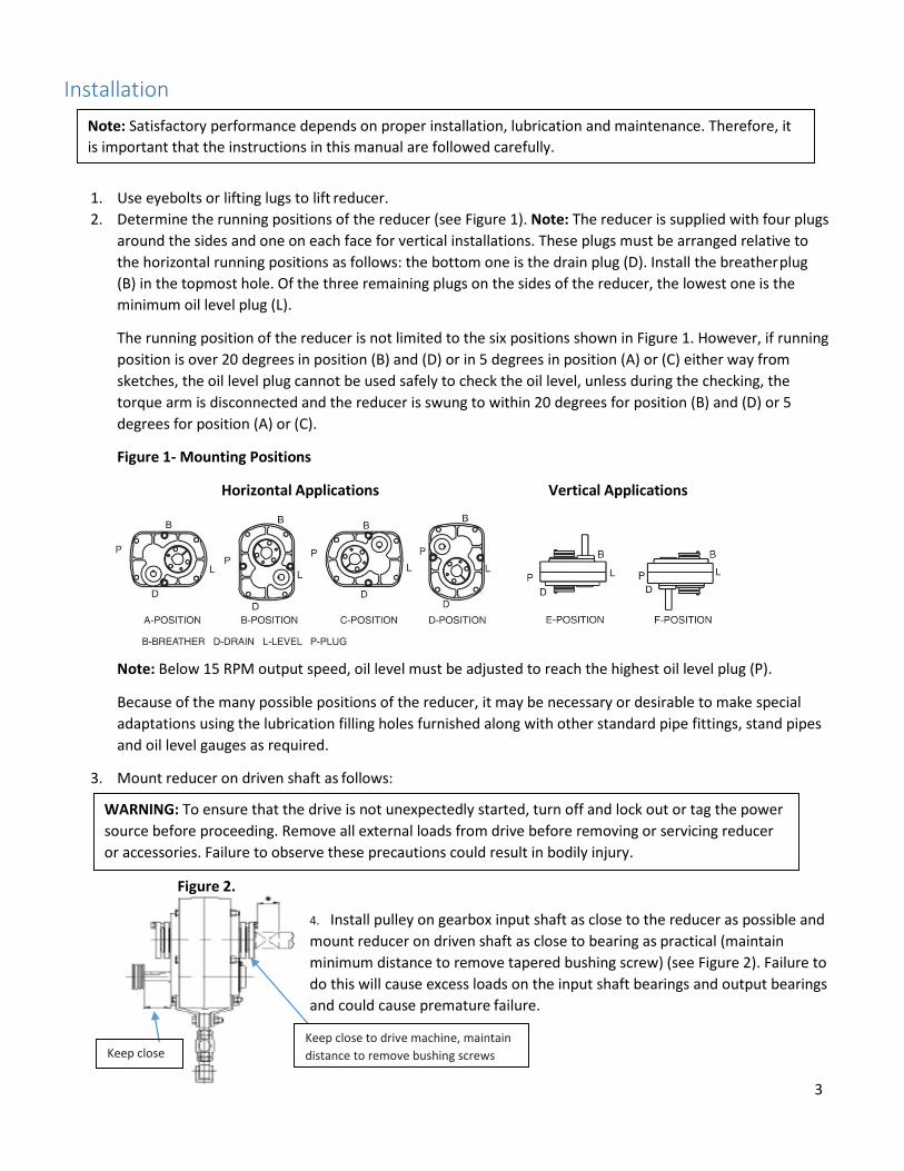
Keep close Keep close to drive machine, maintain distance to remove bushing screws
Installation
1. Use eyebolts or lifting lugs to lift reducer. 2. Determine the running positions of the reducer (see Figure 1). Note: The reducer is supplied with four plugs
around the sides and one on each face for vertical installations. These plugs must be arranged relative to the horizontal running positions as follows: the bottom one is the drain plug (D). Install the breather plug (B) in the topmost hole. Of the three remaining plugs on the sides of the reducer, the lowest one is the minimum oil level plug (L).
The running position of the reducer is not limited to the six positions shown in Figure 1. However, if running position is over 20 degrees in position (B) and (D) or in 5 degrees in position (A) or (C) either way from sketches, the oil level plug cannot be used safely to check the oil level, unless during the checking, the torque arm is disconnected and the reducer is swung to within 20 degrees for position (B) and (D) or 5 degrees for position (A) or (C).
Figure 1- Mounting Positions
Horizontal Applications Vertical Applications
Note: Below 15 RPM output speed, oil level must be adjusted to reach the highest oil level plug (P).
Because of the many possible positions of the reducer, it may be necessary or desirable to make special adaptations using the lubrication filling holes furnished along with other standard pipe fittings, stand pipes and oil level gauges as required.
3. Mount reducer on driven shaft as follows:
Figure 2.
4. Install pulley on gearbox input shaft as close to the reducer as possible and mount reducer on driven shaft as close to bearing as practical (maintain minimum distance to remove tapered bushing screw) (see Figure 2). Failure to do this will cause excess loads on the input shaft bearings and output bearings and could cause premature failure.

4
Belt drive may be located to the right if desired.
If the output hub rotates clock-wise, relocate the belt drive and torque arm in opposite direction to that shown in the illustration.
Torque arm may be mounted to the right if desired.
This angle should be a right angle, but may vary up to a maximum of 30 degrees either way.
Torque arm and belt may vary up to a take-up.
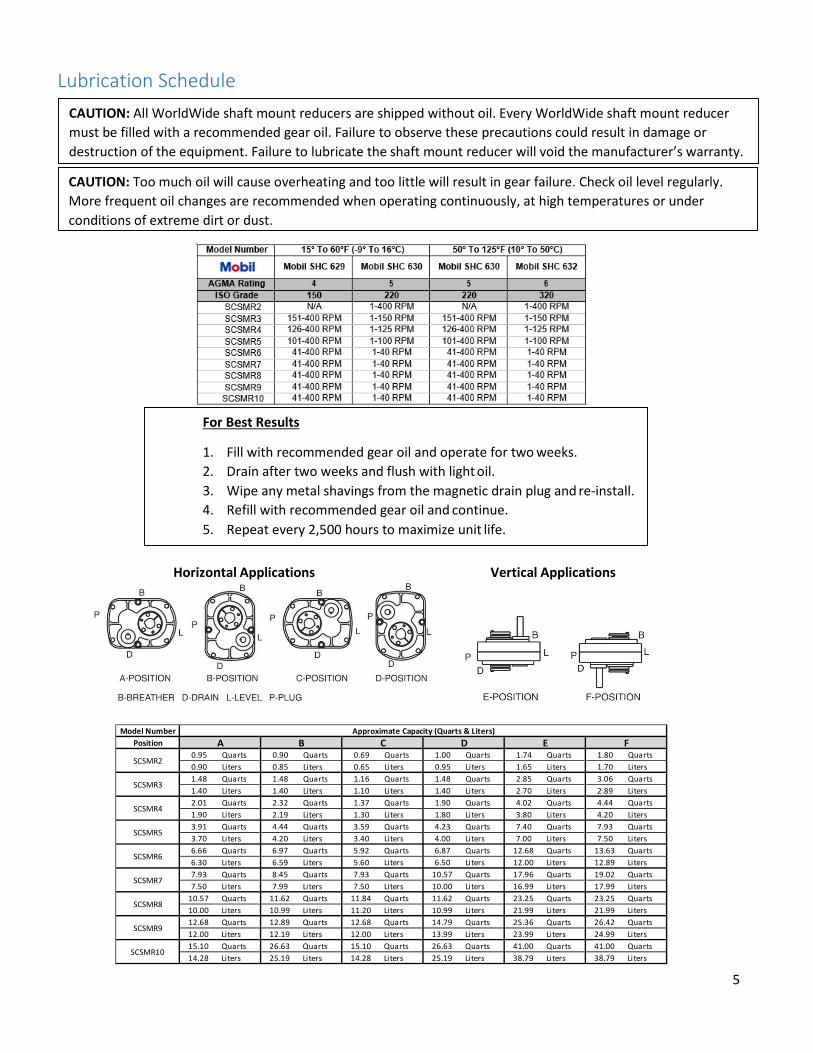
CAUTION: All WorldWide shaft mount reducers are shipped without oil. Every WorldWide shaft mount reducer must be filled with a recommended gear oil. Failure to observe these precautions could result in damage to or destruction of the equipment. Failure to lubricate the shaft mount reducer will void the manufacturer’s warranty.
Figure 3.
5. Install motor and wedge belt drive with the belt pulley at approximately 90 degrees to the center line
between driven and input shafts (see Figure 3). This will permit tensioning of the wedge belt drive with the torque arm which should preferably be in tension. If output hub runs counter- clockwise, torque arm should be positioned to the right (see Figure 4).
Figure 4.
6. Install torque arm fulcrum on a rigid support so that the torque arm will be at approximately 90 degrees to
the center line through the driven shaft and the torque arm case bolt (see Figure 5). If output hub rotates clock- wise, belt drive and torque arm in opposite direction to that shown in the illustration.
Figure 5.
CAUTION: Failure to install the breather plug may result in gearbox overheating and will prematurely cause the oil seals to leak. Failure to install the breather plug in the shaft mount reducer will void the manufacturer’s warranty.
Belt drive may be located in any convenient position. If the torque arm is to be used to tighten the belts, the drive should be at about 90 degrees to the line between the input and output shafts.
5
CAUTION: Too much oil will cause overheating and too little will result in gear failure. Check oil level regularly. More frequent oil changes are recommended when operating continuously, at high temperatures or under conditions of extreme dirt or dust.
CAUTION: All WorldWide shaft mount reducers are shipped without oil. Every WorldWide shaft mount reducer must be filled with a recommended gear oil. Failure to observe these precautions could result in damage or destruction of the equipment. Failure to lubricate the shaft mount reducer will void the manufacturer’s warranty.
Lubrication Schedule
Horizontal Applications Vertical Applications
Model Number
Position0.95 Quarts 0.90 Quarts 0.69 Quarts 1.00 Quarts 1.74 Quarts 1.80 Quarts0.90 Liters 0.85 Liters 0.65 Liters 0.95 Liters 1.65 Liters 1.70 Liters1.48 Quarts 1.48 Quarts 1.16 Quarts 1.48 Quarts 2.85 Quarts 3.06 Quarts1.40 Liters 1.40 Liters 1.10 Liters 1.40 Liters 2.70 Liters 2.89 Liters2.01 Quarts 2.32 Quarts 1.37 Quarts 1.90 Quarts 4.02 Quarts 4.44 Quarts1.90 Liters 2.19 Liters 1.30 Liters 1.80 Liters 3.80 Liters 4.20 Liters3.91 Quarts 4.44 Quarts 3.59 Quarts 4.23 Quarts 7.40 Quarts 7.93 Quarts3.70 Liters 4.20 Liters 3.40 Liters 4.00 Liters 7.00 Liters 7.50 Liters6.66 Quarts 6.97 Quarts 5.92 Quarts 6.87 Quarts 12.68 Quarts 13.63 Quarts6.30 Liters 6.59 Liters 5.60 Liters 6.50 Liters 12.00 Liters 12.89 Liters7.93 Quarts 8.45 Quarts 7.93 Quarts 10.57 Quarts 17.96 Quarts 19.02 Quarts7.50 Liters 7.99 Liters 7.50 Liters 10.00 Liters 16.99 Liters 17.99 Liters
10.57 Quarts 11.62 Quarts 11.84 Quarts 11.62 Quarts 23.25 Quarts 23.25 Quarts10.00 Liters 10.99 Liters 11.20 Liters 10.99 Liters 21.99 Liters 21.99 Liters12.68 Quarts 12.89 Quarts 12.68 Quarts 14.79 Quarts 25.36 Quarts 26.42 Quarts12.00 Liters 12.19 Liters 12.00 Liters 13.99 Liters 23.99 Liters 24.99 Liters15.10 Quarts 26.63 Quarts 15.10 Quarts 26.63 Quarts 41.00 Quarts 41.00 Quarts14.28 Liters 25.19 Liters 14.28 Liters 25.19 Liters 38.79 Liters 38.79 Liters
SCSMR8
SCSMR9
SCSMR10
SCSMR2
SCSMR3
SCSMR4
SCSMR5
SCSMR6
SCSMR7
Approximate Capacity (Quarts & Liters)A B C D E F
For Best Results
1. Fill with recommended gear oil and operate for two weeks. 2. Drain after two weeks and flush with light oil. 3. Wipe any metal shavings from the magnetic drain plug and re-install. 4. Refill with recommended gear oil and continue. 5. Repeat every 2,500 hours to maximize unit life.

6
WARNING: To ensure that drive is not unexpectedly started, turn off and lock out or tag power source before proceeding. Failure to observe these precautions could result in bodily harm.
Replacement of Parts
Important: Using tools normally found in a maintenance department, shaft mount reducers can be disassembled and re-assembled by careful attention to the instructions following. Cleanliness is very important to prevent the introduction of dirt into the bearings and other parts of the reducer. A tank of clean solvent, an arbor press, and equipment for heating bearings and gears (for shrinking these parts on shafts) should be available. The oil seals are of the rubbing type and considerable care should be used during disassembly and re-assembly to avoid damage to the surface which the seals rub on. The key-seat in the input shaft, as well as any sharp edges on the output hub should be covered with tape or paper before disassembly or re-assembly. Also, be careful to remove any burrs or nicks on surfaces of the input shaft or out hub before disassembly or re-assembly.
Ordering Parts: When ordering parts for reducer, specify reducer size number, part name, part number, and quantity. It is strongly recommended that, when a pinion or gear is replaced, the mating pinion or gear is replaced also. If the large gear on the output hub must be replaced, it is recommended that an output hub assembly of a gear assembly on a hub be ordered to secure undamaged surfaces on the output hub where the output seals rub. However, if it is desired to use the old output hub press the gear and bearing off and examine the rubbing surface under the oil seal carefully for possible scratching or other damage resulting from the pressing operation. To prevent oil leakage at the shaft oil seals, the smooth surface of the output hub must not be damaged. If any parts must be pressed from a shaft or from the output hub, this should be done before ordering parts to make sure that none of the bearings or other parts are damaged in removal. Do not press against outer race of any bearing. Because old shaft rubber oil seals may be damaged in disassembly, it is advisable to order replacements for these parts.
REMOVING REDUCER FROM SHAFT
1. Remove bushing screws. 2. Place the screws in the threaded holes provided in the bushing flanges. Tighten the screws alternately and
evenly until the bushings are free on the shaft. For ease of tightening screws, make sure screw threads and threaded holes in bushing flanges are clean.
DISASSEMBLY
1. Position the reducer on its side and remove all housing bolts. Drive dowel pins from housing. Gently tap the output hub and input shaft with a soft hammer (rawhide, not a lead hammer) to separate the housing halves. Open housing evenly to prevent damage to the parts inside.
2. Lift shaft gear and bearing assemblies from housing. 3. Remove seals from housing.
RE-ASSEMBLY
1. Output Hub Assembly: Heat gear to 120 degrees Celsius to shrink onto hub. Heat bearings to 100 degrees Celsius to shrink onto hub. Any injury to hub surfaces where the oil seals rub will cause leakage, making it necessary to use a new hub. When pressing bearings onto the hub, do not apply force against the inner ring only.
CAUTION: Remove oil external loads from drive before removing or servicing drive or accessories.

7
2. Counter shaft Assembly: Heat the gear to 120 degrees Celsius and press onto the shaft. Heat the bearings to 100 degrees Celsius and press onto shaft. When pressing bearings onto the shaft, do not apply force against the inner ring only.
3. Input Shaft Assembly: Heat the bearings to 100 degrees Celsius and then press them onto the shaft. Press against the inner (not outer) race of the bearings (for SCSMR2 press against the ball bearing on the shaft).
4. Drive the two dowel pins into place in the right- hand housing half. Apply sealant to carriers for R. H. side (back stop side) of reducer. Install carriers and torque bolts with 30-27 foot-pounds for SCSMR3 to 6, 50-45 foot-pounds for SCSMR7 to 10. SCSMR2’s do not have these carriers.
5. Place R. H. housing half on block to allow for protruding end of output hub. 6. Install bearing cups in right- hand housing half, making sure they are properly sealed (for SCSMR2 do not
have this step). 7. Mesh output hub gear and small counter shaft gear together and set in place in housing. Make sure bearing
rollers (cones) are properly seated in their cups. Set bearing cups for left- handed housing half in place on their rollers (except SCSMR2).
8. Clean housing flange surfaces on both halves, making sure not to nick or scratch the face. Apply sealant to flange face (make sure that the sealant is placed between bolt holes and inside of the surface). Place L.H. housing into position and tap with a soft hammer (rawhide, not lead hammer) until housing bolts can be used to draw housing halves together. Torque housing bolts per torque values 30- 27 foot-pounds for SCSMR2, 50- 45 foot-pounds for SCSMR3 to 4, 75-68 foot-pounds for SCSMR5 to 6, 150- 135 foot-pounds for SCSMR7 to SCSMR10.
9. Place output hub seal carrier into position without shims and install two carrier screws diametrically opposed. Torque each screw to 25 inch-pounds. Rotate the output hub to roll in the bearings and then torque each screw to 50 inch-pounds. Again turn output hub to roll in the bearings. With a shim thickness, take the average of the two feeler gauge readings. Remove carrier and install the required shims plus 0.002”. Install carrier with shims and torque bolts per torque values 17- 15 foot-pounds for SCSMR3, 30- 27 foot-pounds for SCSMR4 to 6, and 50- 45 foot-pounds for SCSMR7- 10. The SCSMR2 does not require this step. Rotate hub assembly, tap lightly with rawhide mallet on end of hub, while rotating, to ensure bearings are sealed. Using a dial indicator check end play of hub bearings, end play should be 0.001”- 0.004” for SCSMR3 to SCSMR6 and 0.002” to 0.004” for SCSMR7 to SCSMR10. Repeat this process as necessary to obtain proper end play. Place sealant inside the carrier at the shim I.D. and install carrier on reducer housing. Torque carrier bolts to value 17- 15 foot-pounds for SCSMR3, 30- 27 foot-pounds for SCSMR4 to 6, and 50-45 foot-pounds for SCSMR7 to 10. The SCSMR2 do not require this step.
10. Adjust the counter shaft bearings using the same method as in step 9 above. The axial end play should be 0.001" to 0.004" for SCSMR3 to SCSMR6 and 0.002” to 0.005” for SCSMR7 to WSMR10.
11. Again, using the same procedure as in step 9, adjust the input shaft bearing, except the axial end play should be 0.001" to 0.004" for SCSMR3 to SCSMR6 and 0.002” to 0.005” for SCSMR7 to SCSMR10. Using gaskets install input shaft cover and counter shaft cover to right- handed housing half. Install input and output seals. Extreme care should be used when installing seals to avoid damage due to contact with sharp edges on the input shaft or output hub. The possibility of damage and consequent oil leakage can be decreased by covering all sharp edges with tape prior to seal installation. Fill cavity between seal lips with grease. Seals should be pressed or tapped with soft hammer evenly into place in the carrier, applying pressure only on the outer edge of the seals. A slight oil leakage the seals may be evident during initial running, but should disappear unless seals have been damaged.
12. Install bushing backup plates and snap rings on Taper Bushing reducers. (Please note SMR6, 8, 9's snap rings have a little notch for the bushing screw, and the notch must have a right angle to output hub's key seat.)
8
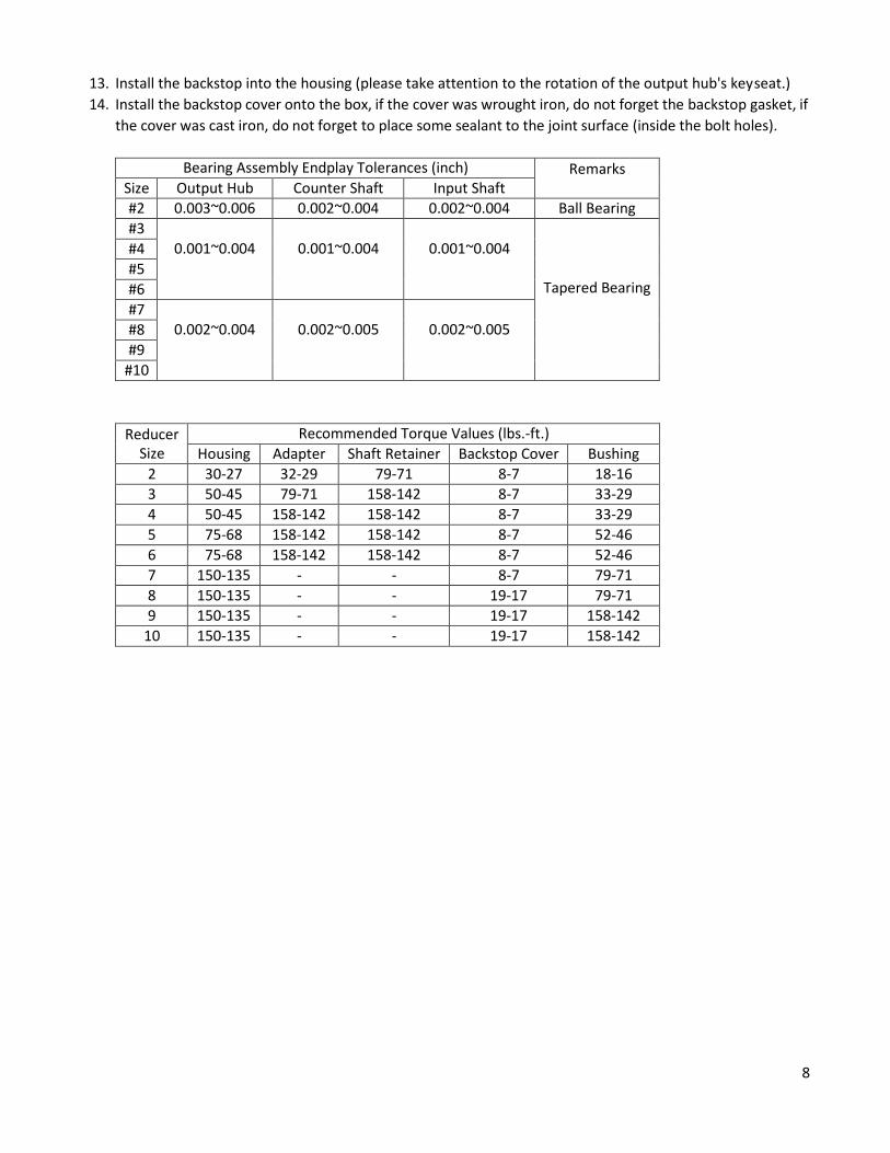
13. Install the backstop into the housing (please take attention to the rotation of the output hub's key seat.) 14. Install the backstop cover onto the box, if the cover was wrought iron, do not forget the backstop gasket, if
the cover was cast iron, do not forget to place some sealant to the joint surface (inside the bolt holes).
Bearing Assembly Endplay Tolerances (inch) Remarks Size Output Hub Counter Shaft Input Shaft #2 0.003~0.006 0.002~0.004 0.002~0.004 Ball Bearing #3
0.001~0.004
0.001~0.004
0.001~0.004
Tapered Bearing
#4 #5 #6 #7
0.002~0.004
0.002~0.005
0.002~0.005 #8 #9
#10
Reducer
Size Recommended Torque Values (lbs.-ft.)
Housing Adapter Shaft Retainer Backstop Cover Bushing 2 30-27 32-29 79-71 8-7 18-16 3 50-45 79-71 158-142 8-7 33-29 4 50-45 158-142 158-142 8-7 33-29 5 75-68 158-142 158-142 8-7 52-46 6 75-68 158-142 158-142 8-7 52-46 7 150-135 - - 8-7 79-71 8 150-135 - - 19-17 79-71 9 150-135 - - 19-17 158-142
10 150-135 - - 19-17 158-142
9
Reducer
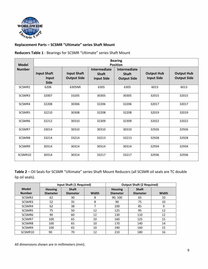
Replacement Parts – SCSMR “Ultimate” series Shaft Mount
Reducers Table 1 - Bearings for SCSMR “Ultimate” series Shaft Mount
Model
Number
Bearing Position
Input Shaft
Input Side
Input Shaft Output Side
Intermediate Shaft
Input Side
Intermediate Shaft
Output Side
Output Hub Input Side
Output Hub Output Side
SCSMR2 6206 6305NR 6305 6305 6013 6013
SCSMR3 32007 33205 30305 30305 32015 32015
SCSMR4 32208 30306 32206 32206 32017 32017
SCSMR5 32210 30308 32208 32208 32019 32019
SCSMR6 32212 30310 32309 32309 32022 32022
SCSMR7 33014 30310 30310 30310 32926 32926
SCSMR8 33214 33214 33213 33213 32928 32928
SCSMR9 30314 30314 30314 30314 32934 32934
SCSMR10 30314 30314 33217 33217 32936 32936
Table 2 – Oil Seals for SCSMR “Ultimate” series Shaft Mount Reducers (all SCSMR oil seals are TC double lip oil seals).
Model
Number
Input Shaft (1 Required) Output Shaft (2 Required) Housing
Diameter Shaft
Diameter
Width Housing
Diameter Shaft
Diameter
Width SCSMR2 62 30 8 90, 100 65 10 SCSMR3 52 35 8 90 75 10 SCSMR4 62 38 7 100 85 9 SCSMR5 75 50 12 125 95 12 SCSMR6 90 60 12 130 110 12 SCSMR7 100 65 10 160 125 15 SCSMR8 100 65 10 170 140 14 SCSMR9 100 65 10 190 160 15
SCSMR10 90 70 12 210 180 16
All dimensions shown are in millimeters (mm).
10
WARNING: To ensure that the drive is not unexpectedly started, turn off and lock out or tag the power source before proceeding. Failure to observe these precautions could result in bodily harm or death.
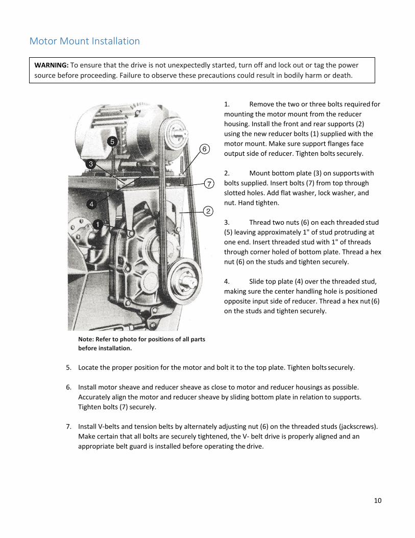
Motor Mount Installation
Note: Refer to photo for positions of all parts before installation.
1. Remove the two or three bolts required for mounting the motor mount from the reducer housing. Install the front and rear supports (2) using the new reducer bolts (1) supplied with the motor mount. Make sure support flanges face output side of reducer. Tighten bolts securely.
2. Mount bottom plate (3) on supports with bolts supplied. Insert bolts (7) from top through slotted holes. Add flat washer, lock washer, and nut. Hand tighten.
3. Thread two nuts (6) on each threaded stud (5) leaving approximately 1" of stud protruding at one end. Insert threaded stud with 1" of threads through corner holed of bottom plate. Thread a hex nut (6) on the studs and tighten securely.
4. Slide top plate (4) over the threaded stud, making sure the center handling hole is positioned opposite input side of reducer. Thread a hex nut (6) on the studs and tighten securely.
5. Locate the proper position for the motor and bolt it to the top plate. Tighten bolts securely.
6. Install motor sheave and reducer sheave as close to motor and reducer housings as possible. Accurately align the motor and reducer sheave by sliding bottom plate in relation to supports. Tighten bolts (7) securely.
7. Install V-belts and tension belts by alternately adjusting nut (6) on the threaded studs (jackscrews).
Make certain that all bolts are securely tightened, the V- belt drive is properly aligned and an appropriate belt guard is installed before operating the drive.
11
WARNING: Failure to install a backstop assembly correctly can result in injury to personnel and/or destruction of the backstop assembly, the speed reducer and other property. Read all backstop installation instructions completely before installing a backstop assembly. Certain size speed reducers require the installation of a circlip (snap ring) on the input shaft for the purposes of keeping the backstop assembly from moving in an axial direction on the input shaft during speed reducer operation. Failure to install this circlip (snap ring) may result in backstop failure and can destroy the speed reducer.
CAUTION: To avoid premature failure of the backstop or possible machine malfunction, installation of the backstop should be carried out by suitably qualified personnel and according to the following instructions:
Backstop Installation
Backstop Description
1. The main components of the WSMR#BSK and SCSMR#BSK units are: Inner race (if applicable), outer race, a number of energized sprags and side plate.
2. The maximum permissible overrunning speed must not be exceeded. 3. When used in dual drive applications, the maximum driving speed must not be exceeded. 4. Backstops (cam clutches) are shaft mounted, so the shaft on which the clutch is mounted must be
hardened to HRC 56-60 and 1.5 mm case depth after grinding. Grind to 1.5S (16 micro-inch) finish. The taper of this shaft should not exceed 0.01 mm per 50 mm.
Prior to Installation 1. The units should be unpacked and installed in a clean dry working environment. 2. For units dispatched ‘dry’, corrosion inhibitor should be removed using flushing oil prior to Installation. 3. The inner race should be fitted to a shaft of (-0.01mm to -0.025mm) tolerance if the unit is supplied
with a metric bore. Details for each type are shown in the dimensions tables on page 14. 4. The mounting register for the outer race should be within the housing bore (0mm to +0.03mm)
tolerance. Details for each type are shown in the dimensions tables on pages 14. 5. The freewheeling direction should be checked prior to installation (see Backstop Assembly Type and
Rotation Illustrations below). 6. If reversal of the freewheeling direction is required, turn the backstop through 180 degrees.
WARNING: Use only WorldWide Electric Corporation WSMR#BSK and SCSMR#BSK style backstop assemblies in the “Eliminator” series shaft mount reducers. Do not use any other brand or style of backstop assemblies in these speed reducers. Using other brands or styles of backstop assemblies may result in backstop assembly failure and may result in jury to personnel or property. Using another manufacturer or style of backstop assembly in the “Ultimate” series shaft mount reducer will void the manufacturer’s warranty of the speed reducer and the backstop assembly.
WARNING TO ELECTRICIANS: Before powering up equipment that contains a shaft mount reducer containing an installed backstop assembly, disconnect the v-belts from the motor sheave and confirm the rotation direction of the motor. Applying power to the motor in a reverse direction against the free wheel direction of the backstop assembly will destroy the backstop assembly and possibly destroy the shaft mount reducer as well. Failure to comply with this instruction will void the manufacturer’s warranty of the speed reducer and the backstop assembly and may result in injury to personnel or property.
12
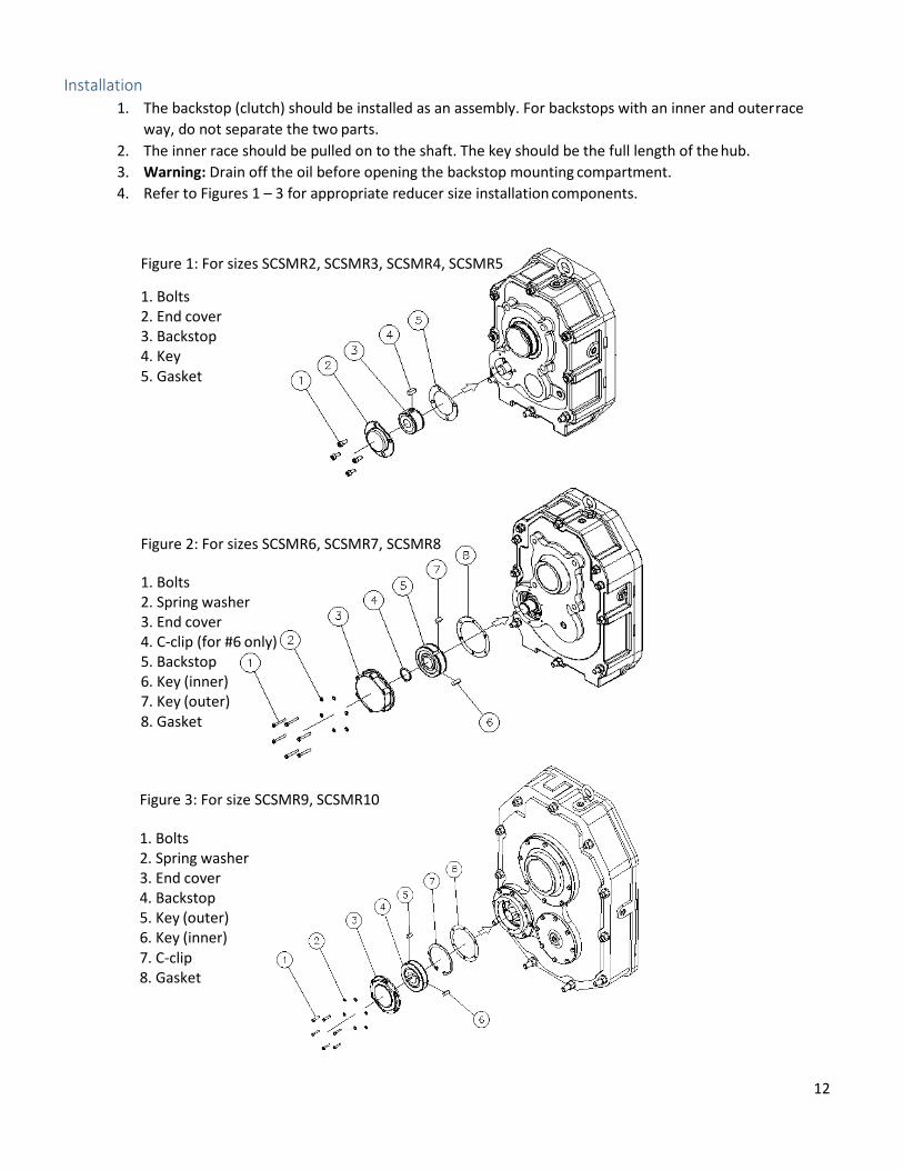
Installation 1. The backstop (clutch) should be installed as an assembly. For backstops with an inner and outer race
way, do not separate the two parts. 2. The inner race should be pulled on to the shaft. The key should be the full length of the hub. 3. Warning: Drain off the oil before opening the backstop mounting compartment. 4. Refer to Figures 1 – 3 for appropriate reducer size installation components.
Figure 1: For sizes SCSMR2, SCSMR3, SCSMR4, SCSMR5
1. Bolts 2. End cover 3. Backstop 4. Key 5. Gasket
Figure 2: For sizes SCSMR6, SCSMR7, SCSMR8
1. Bolts 2. Spring washer 3. End cover 4. C-clip (for #6 only) 5. Backstop 6. Key (inner) 7. Key (outer) 8. Gasket
Figure 3: For size SCSMR9, SCSMR10
1. Bolts 2. Spring washer 3. End cover 4. Backstop 5. Key (outer) 6. Key (inner) 7. C-clip 8. Gasket
13
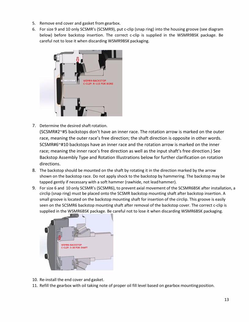
5. Remove end cover and gasket from gearbox. 6. For size 9 and 10 only SCSMR’s (SCSMR9), put c-clip (snap ring) into the housing groove (see diagram
below) before backstop insertion. The correct c-clip is supplied in the WSMR9BSK package. Be careful not to lose it when discarding WSMR9BSK packaging.
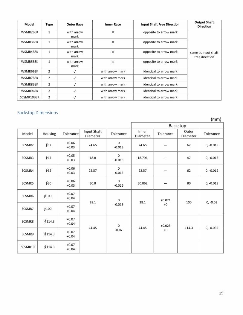
7. Determine the desired shaft rotation.
(SCSMR#2~#5 backstops don’t have an inner race. The rotation arrow is marked on the outer race, meaning the outer race’s free direction; the shaft direction is opposite in other words. SCSMR#6~#10 backstops have an inner race and the rotation arrow is marked on the inner race; meaning the inner race’s free direction as well as the input shaft’s free direction.) See Backstop Assembly Type and Rotation Illustrations below for further clarification on rotation directions.
8. The backstop should be mounted on the shaft by rotating it in the direction marked by the arrow shown on the backstop race. Do not apply shock to the backstop by hammering. The backstop may be tapped gently if necessary with a soft hammer (rawhide, not lead hammer).
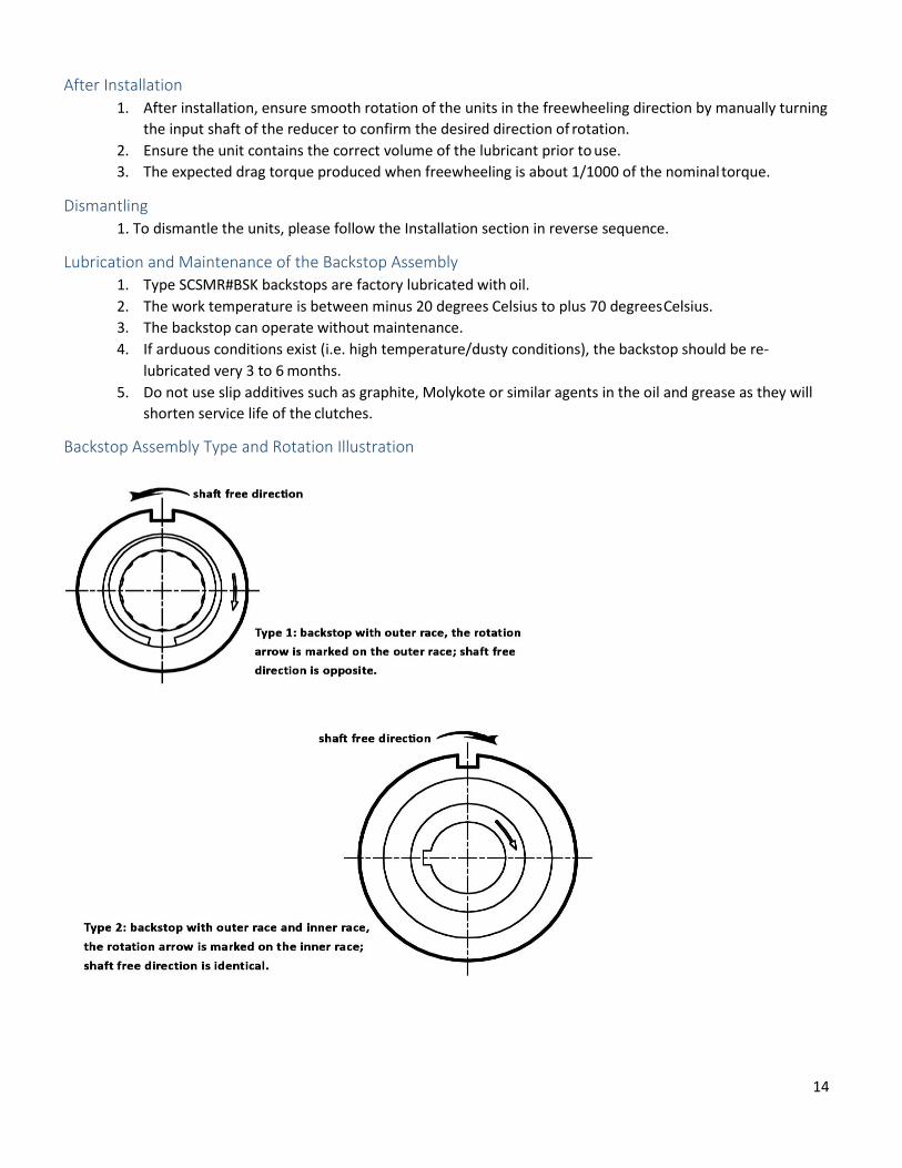
9. For size 6 and 10 only SCSMR’s (SCSMR6), to prevent axial movement of the SCSMR6BSK after installation, a circlip (snap ring) must be placed onto the SCSMR backstop mounting shaft after backstop insertion. A small groove is located on the backstop mounting shaft for insertion of the circlip. This groove is easily seen on the SCSMR6 backstop mounting shaft after removal of the backstop cover. The correct c-clip is supplied in the WSMR6BSK package. Be careful not to lose it when discarding WSMR6BSK packaging.
10. Re-install the end cover and gasket. 11. Refill the gearbox with oil taking note of proper oil fill level based on gearbox mounting position.
14
After Installation 1. After installation, ensure smooth rotation of the units in the freewheeling direction by manually turning
the input shaft of the reducer to confirm the desired direction of rotation. 2. Ensure the unit contains the correct volume of the lubricant prior to use. 3. The expected drag torque produced when freewheeling is about 1/1000 of the nominal torque.
Dismantling 1. To dismantle the units, please follow the Installation section in reverse sequence.
Lubrication and Maintenance of the Backstop Assembly 1. Type SCSMR#BSK backstops are factory lubricated with oil. 2. The work temperature is between minus 20 degrees Celsius to plus 70 degrees Celsius. 3. The backstop can operate without maintenance. 4. If arduous conditions exist (i.e. high temperature/dusty conditions), the backstop should be re-
lubricated very 3 to 6 months. 5. Do not use slip additives such as graphite, Molykote or similar agents in the oil and grease as they will
shorten service life of the clutches.
Backstop Assembly Type and Rotation Illustration
15
Model Type Outer Race Inner Race Input Shaft Free Direction Output Shaft Direction
WSMR2BSK 1 with arrow mark
✕ opposite to arrow mark
same as input shaft free direction
WSMR3BSK 1 with arrow mark
✕ opposite to arrow mark
WSMR4BSK 1 with arrow mark
✕ opposite to arrow mark
WSMR5BSK 1 with arrow mark
✕ opposite to arrow mark
WSMR6BSK 2 ✓ with arrow mark identical to arrow mark
WSMR7BSK 2 ✓ with arrow mark identical to arrow mark
WSMR8BSK 2 ✓ with arrow mark identical to arrow mark
WSMR9BSK 2 ✓ with arrow mark identical to arrow mark
SCSMR10BSK 2 ✓ with arrow mark identical to arrow mark
Backstop Dimensions (mm)
Backstop
Model Housing Tolerance Input Shaft Diameter Tolerance Inner
Diameter Tolerance Outer Diameter Tolerance
SCSMR2
∮62 +0.06
+0.03
24.65 0
-0.013
24.65
---
62
0, -0.019
SCSMR3
∮47 +0.05
+0.03
18.8 0
-0.013
18.796
---
47
0, -0.016
SCSMR4
∮62 +0.06
+0.03
22.57 0
-0.013
22.57
---
62
0, -0.019
SCSMR5
∮80 +0.06
+0.03
30.8 0
-0.016
30.862
---
80
0, -0.019
SCSMR6
∮100 +0.07
+0.04
38.1
0 -0.016
38.1
+0.021 +0
100
0, -0.03
SCSMR7
∮100 +0.07
+0.04
SCSMR8
∮114.3 +0.07
+0.04
44.45
0 -0.02
44.45
+0.025 +0
114.3
0, -0.035 SCSMR9
∮114.3 +0.07
+0.04
SCSMR10
∮114.3 +0.07
+0.04
16
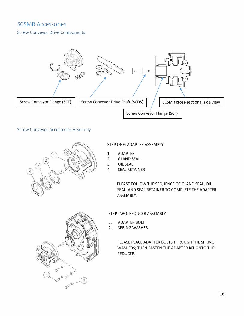
Screw Conveyor Flange (SCF) SCSMR cross-sectional side view Screw Conveyor Drive Shaft (SCDS)
SCSMR Accessories Screw Conveyor Drive Components
Screw Conveyor Accessories Assembly
STEP ONE: ADAPTER ASSEMBLY
1. ADAPTER 2. GLAND SEAL 3. OIL SEAL 4. SEAL RETAINER
PLEASE FOLLOW THE SEQUENCE OF GLAND SEAL, OIL SEAL, AND SEAL RETAINER TO COMPLETE THE ADAPTER ASSEMBLY.
STEP TWO: REDUCER ASSEMBLY
1. ADAPTER BOLT 2. SPRING WASHER
PLEASE PLACE ADAPTER BOLTS THROUGH THE SPRING WASHERS; THEN FASTEN THE ADAPTER KIT ONTO THE REDUCER.
Screw Conveyor Flange (SCF)

17
STEP THREE: DRIVE SHAFT ASSEMBLY
1. DRIVE SHAFT 2. DRIVE SHAFT KEY 3. BUSHING (Sleeve) 4. SHAFT RETAINER 5. SPRING WASHER 6. BOLT
FIRST, STRIKE THE KEY ONTO THE SHAFT. SECOND, PLACE THE SHAFT THROUGH THE REDUCER. THIRD, PLACE THE BUSHING INTO HOLLOW SHAFT. FOURTH, PLACE THE SPRING WASHER THROUGH THE BOLT AND SHAFT RETAINER THEN FASTEN IT ON TO THE DRIVE SHAFT.
Screw Conveyor Flange Adapters
Reducer Size Drive Shaft Dia. J K A FIG.
#2
1-1/2 4 1/2-13UNC
7.75
1
2 5-1/8 5/8
2-7/16 5-5/8 5/8
3 6 3/4
#3
1-1/2 4 1/2-13UNC
8.50 2 5-1/8 5/8
2-7/16 5-5/8 5/8
3 6 3/4
#4
1-1/2 4 1/2-13UNC
9.26 2 5-1/8 5/8
2-7/16 5-5/8 5/8
3 6 3/4
3-7/16 6-3/4 3/4
18
#5
2 5-1/8 5/8
9.26
2
2-7/16 5-5/8 5/8
3 6 3/4
3-7/16 6-3/4 3/4
#6
2-7/16 5-5/8 5/8 9.26 3 6 3/4
3-7/16 6-3/4 3/4
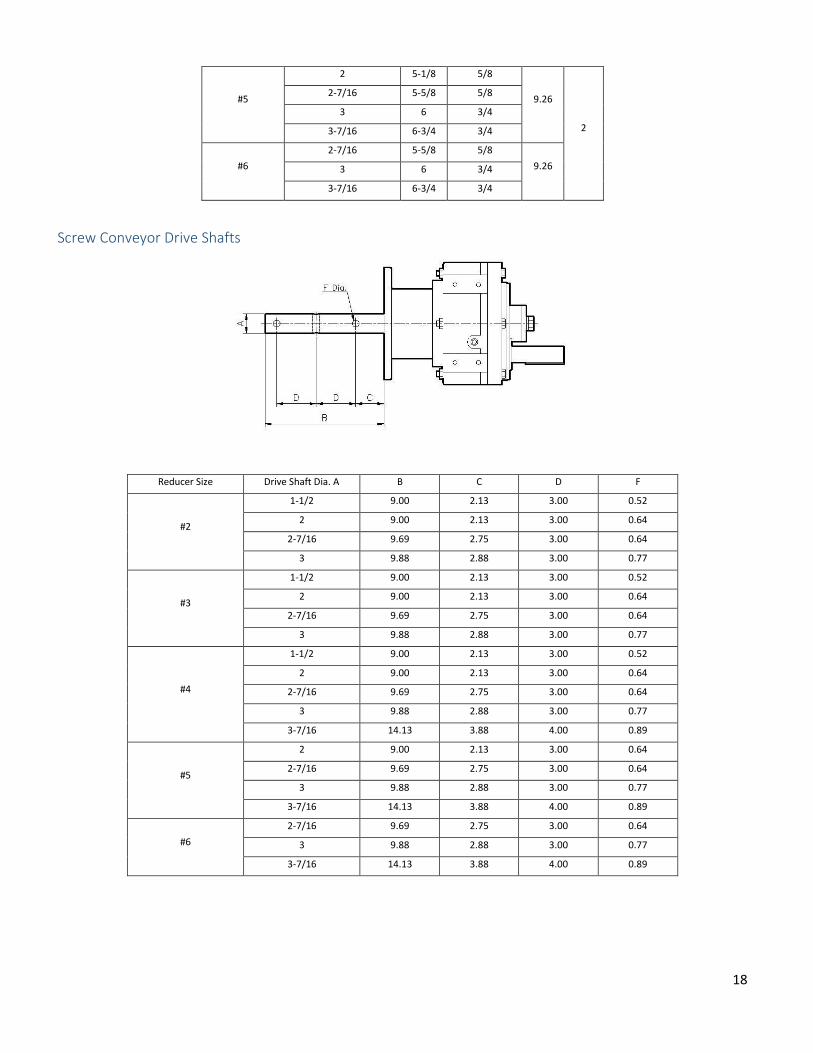
Screw Conveyor Drive Shafts
Reducer Size Drive Shaft Dia. A B C D F
#2
1-1/2 9.00 2.13 3.00 0.52
2 9.00 2.13 3.00 0.64
2-7/16 9.69 2.75 3.00 0.64
3 9.88 2.88 3.00 0.77
#3
1-1/2 9.00 2.13 3.00 0.52
2 9.00 2.13 3.00 0.64
2-7/16 9.69 2.75 3.00 0.64
3 9.88 2.88 3.00 0.77
#4
1-1/2 9.00 2.13 3.00 0.52
2 9.00 2.13 3.00 0.64
2-7/16 9.69 2.75 3.00 0.64
3 9.88 2.88 3.00 0.77
3-7/16 14.13 3.88 4.00 0.89
#5
2 9.00 2.13 3.00 0.64
2-7/16 9.69 2.75 3.00 0.64
3 9.88 2.88 3.00 0.77
3-7/16 14.13 3.88 4.00 0.89
#6
2-7/16 9.69 2.75 3.00 0.64
3 9.88 2.88 3.00 0.77
3-7/16 14.13 3.88 4.00 0.89
19
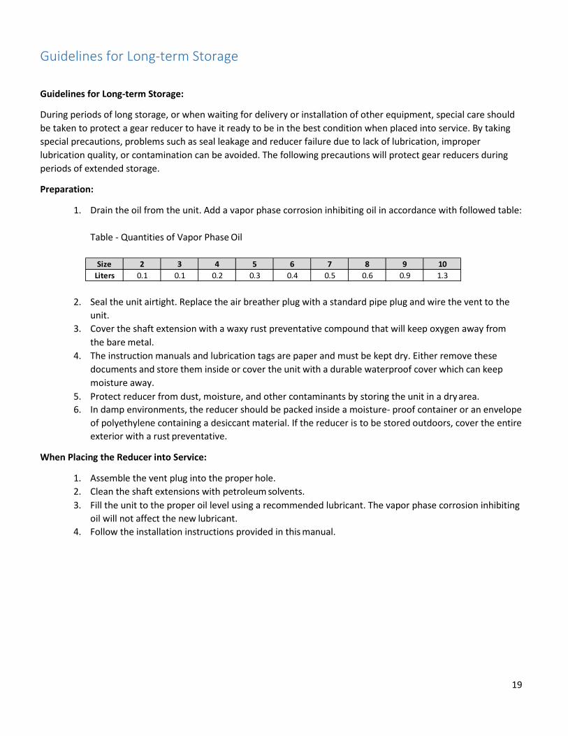
Guidelines for Long-term Storage
Guidelines for Long-term Storage:
During periods of long storage, or when waiting for delivery or installation of other equipment, special care should be taken to protect a gear reducer to have it ready to be in the best condition when placed into service. By taking special precautions, problems such as seal leakage and reducer failure due to lack of lubrication, improper lubrication quality, or contamination can be avoided. The following precautions will protect gear reducers during periods of extended storage.
Preparation:
1. Drain the oil from the unit. Add a vapor phase corrosion inhibiting oil in accordance with followed table:
Table - Quantities of Vapor Phase Oil
2. Seal the unit airtight. Replace the air breather plug with a standard pipe plug and wire the vent to the unit.
3. Cover the shaft extension with a waxy rust preventative compound that will keep oxygen away from the bare metal.
4. The instruction manuals and lubrication tags are paper and must be kept dry. Either remove these documents and store them inside or cover the unit with a durable waterproof cover which can keep moisture away.
5. Protect reducer from dust, moisture, and other contaminants by storing the unit in a dry area. 6. In damp environments, the reducer should be packed inside a moisture- proof container or an envelope
of polyethylene containing a desiccant material. If the reducer is to be stored outdoors, cover the entire exterior with a rust preventative.
When Placing the Reducer into Service:
1. Assemble the vent plug into the proper hole. 2. Clean the shaft extensions with petroleum solvents. 3. Fill the unit to the proper oil level using a recommended lubricant. The vapor phase corrosion inhibiting
oil will not affect the new lubricant. 4. Follow the installation instructions provided in this manual.
Size 2 3 4 5 6 7 8 9 10Liters 0.1 0.1 0.2 0.3 0.4 0.5 0.6 0.9 1.3
20
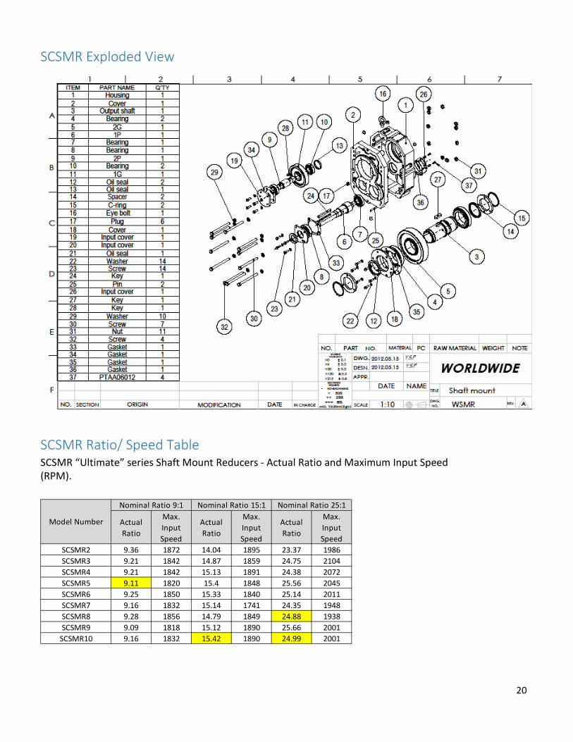
SCSMR Exploded View
SCSMR Ratio/ Speed Table SCSMR “Ultimate” series Shaft Mount Reducers - Actual Ratio and Maximum Input Speed (RPM).
Actual Ratio
Max. Input Speed
Actual Ratio
Max. Input Speed
Actual Ratio
Max. Input Speed
SCSMR2 9.36 1872 14.04 1895 23.37 1986SCSMR3 9.21 1842 14.87 1859 24.75 2104SCSMR4 9.21 1842 15.13 1891 24.38 2072SCSMR5 9.11 1820 15.4 1848 25.56 2045SCSMR6 9.25 1850 15.33 1840 25.14 2011SCSMR7 9.16 1832 15.14 1741 24.35 1948SCSMR8 9.28 1856 14.79 1849 24.88 1938SCSMR9 9.09 1818 15.12 1890 25.66 2001
SCSMR10 9.16 1832 15.42 1890 24.99 2001
Nominal Ratio 9:1 Nominal Ratio 15:1 Nominal Ratio 25:1
Model Number

21
Limited Warranty
Limited Warranty:
WorldWide Electric Corporation (The Company) warranties its products to be free from defect in materials or workmanship to the original purchaser for a period of three (3) years from the date of sale (invoice) for the “Ultimate” series shaft mount reducer. For this warranty to be effective, this product must be installed, used and maintained by the original purchaser in the accordance with good industry standards. The warranty does not cover normal wear, tear and erosion from use, misuse, abuse or corrosion.
In the event of failure, it shall be the responsibility of the original purchaser to notify The Company either in writing or by telephone to make arrangements for the correction of the problem. The purchaser shall be responsible for transportation charges connected with the return, exchange or repair of parts. Returns found defective upon inspection by our warranty department or authorized warranty service agent will be replaced free of charge.
The Company shall not be liable for any labor cost connected with the replacement of the equipment, the replacement of the parts or adjustments to the equipment by the purchaser or their contractor without The Company's prior written approval.
The Company, as the exclusive remedy under this warranty, shall at it's option, repair or replace defective items or, if agreed upon, refund the purchase price less reasonable allowance for depreciation in exchange for product.
THE COMPANY MAKES NO OTHER WARRANTIES AND ALL IMPLIED OR EXPRESSED WARRANTIES AND REPRESENTATIONS, EXCEPT THAT OF TITLE, ARE DISCLAIMED. ALL IMPLIED WARRANTIES INCLUDING MERCHANTABILITY AND FITNESS FOR A PARTICULAR PURPOSE OR USE BUT NOT LIMITED TO JUST THOSE THAT ARE DISCLAIMED. LIABILITY FOR CONSEQUENTIAL, INCIDENTAL OR SPECIAL DAMAGES AND LOSSES UNDER ANY AND ALL WARRANTIES WHETHER IN CONTACT, TORT OR OTHERWISE ARE EXCLUDED TO THE EXTENT EXCLUSION IS PERMITTED BY LAW.