Elign Gear Couplings - Radicon Gear Coupling is used to join two rotating shafts for efficient...
17
Elign Gear Couplings Flexible Couplings CEL-2.00GB0312
Transcript of Elign Gear Couplings - Radicon Gear Coupling is used to join two rotating shafts for efficient...

Elign Gear Couplings
Flexible CouplingsCEL-2.00GB0312
We can create custom engineered transmission solutions of any size and configuration.
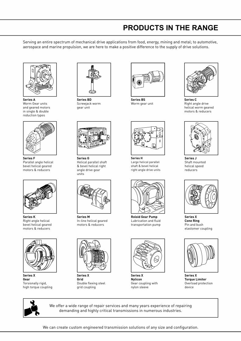
Serving an entire spectrum of mechanical drive applications from food, energy, mining and metal; to automotive, aerospace and marine propulsion, we are here to make a positive difference to the supply of drive solutions.
We offer a wide range of repair services and many years experience of repairing demanding and highly critical transmissions in numerous industries.
Series XCone RingPin and bush elastomer coupling
Series XTorque LimiterOverload protection device
Series JShaft mounted helical speed reducers
Series CRight angle drive helical worm geared motors & reducers
Series BDScrewjack wormgear unit
Series GHelical parallel shaft & bevel helical right angle drive gear units
Series XGridDouble flexing steel grid coupling
Series MIn-line helical geared motors & reducers
Series HLarge helical parallel shaft & bevel helical right angle drive units
Roloid Gear PumpLubrication and fluid transportation pump
Series BSWorm gear unit
Series XNyliconGear coupling with nylon sleeve
Series AWorm Gear units and geared motors in single & double reduction types
Series XGearTorsionally rigid,high torque coupling
Series KRight angle helical bevel helical geared motors & reducers
Series FParallel angle helical bevel helical geared motors & reducers
PRODUCTS IN THE RANGE

ELIGN COUPLINGS
1
INTRODUCTION
A. Radial
When axes of connected shafts are parallel but not in the same straight line.
GEAR COUPLINGS
A Gear Coupling is used to join two rotating shafts for efficient transmission of mechanical power. Although the shafts are ac-curately aligned at the time of installation, it is likely that during the operation the alignment may get disturbed due to setting of foundation, thermal expansion, shaft deflection, wearing out of other parts, improper maintenance and many more reasons. Due to this unavoidable misalignment occurring during the operation a gear coupling provides a better solution to compensate or minimise the effect of misalignment. The gear Couplings are therefore ideally suited for wide range of application in the entire field of drive technology.
MISALIGNMENT
The main function of any Gear coupling is not only to connect two rotating shafts but also to accommodate misalignments of the connecting shafts ELIGN Gear coupling accommodates the following three types of misalignment.
CAUTION.
Normally permissible angular misalignment of ELIGN gear coupling is 0.75 for each half. However, it does not mean that the misalignment should be permitted to this limit from the initial installation. Since misalignment can occur during operation the Elign gear coupling takes care of this without undue damage to the connected equipment. However the coupling’s life may re-duce due to relative motion between hub teeth and housing teeth causing increased wear on the teeth. It is therefore extremely important to align the interconnecting shafts precisely during initial installation.
B. Angular
When axes of connected shafts intersect at the centre point of the coupling but not in the same straight line.
C. Combined radial and angular.
When the axes of connected shafts do not intersect at the point of the coupling and are not parallel.
Besides the above three types of misalignment, the ELIGN Gear coupling range also permit axial movement of the shaft.
FUNCTIONS
B
C
°
A
MISALIGNMENT
A
B
C

ELIGN COUPLINGS
2
FEATURESFEATURES OF ELIGN COUPLINGS
ELIGN Gear coupling consists of hubs with multi crowned teeth at Flank, tip and chamfering on teeth.
Crowned Flanks: The flanks of the teeth are crowned so that the tooth thickness is greatest at that centre of the tooth. This ensures a larger con-tact area per tooth for higher torque requirements and puts more teeth in contact for the given angle. Actual tooth loading takes place near the centre of the tooth face where tooth thickness is greatest, Crowned flanks also eliminate end-of-tooth loading, provide optimal load distribution, and accommodate all types of misalign-ment with minimum backlash.
The hub teeth are manufactured using the latest state of the art CNC machines. The hub is the heart of any gear coupling and a superior design and tooth profile of the hub enables the gear coupling to operate satisfactorily under all operating conditions with increased reliability and durability.
The multi crowned teeth also reduce the alignment adjustment and improve the load carrying capacity of the teeth. The backlash between the teeth is minimal due to the multi-crown tooth design a key feature for the Elign coupling range.
The ELIGN gear coupling is a simple, compact and light unit for transmitting the same power when compered to the couplings of similar capacity available in the market. It is manufactured out of tested quality forged carbon steel and passes through a number of quality checks. Each half of the ELIGN gear coupling is interchangeable with any of other half, of the same size of coupling.
Crowned Tips: The tips of the teeth are crowned. The crowned tip contacts the root of the internal gear teeth in the external sleeve, accurately piloting the sleeve with true concentric ball-and-socket ac-tion. This allows minimum diametral sleeve clearance and centres the sleeve physically to ensure a good dynamic balance under various loading and misalignment conditions.
Crowned Chamfers: The faces of the teeth are adjacent to the tips and are chamfered to eliminate interference with the sleeve tooth fillets. This allows the true involute flanks of the gear teeth to be in contact with the sleeve teeth and ensures freedom to misalign.
3
ELIGN COUPLINGS
SELECTION
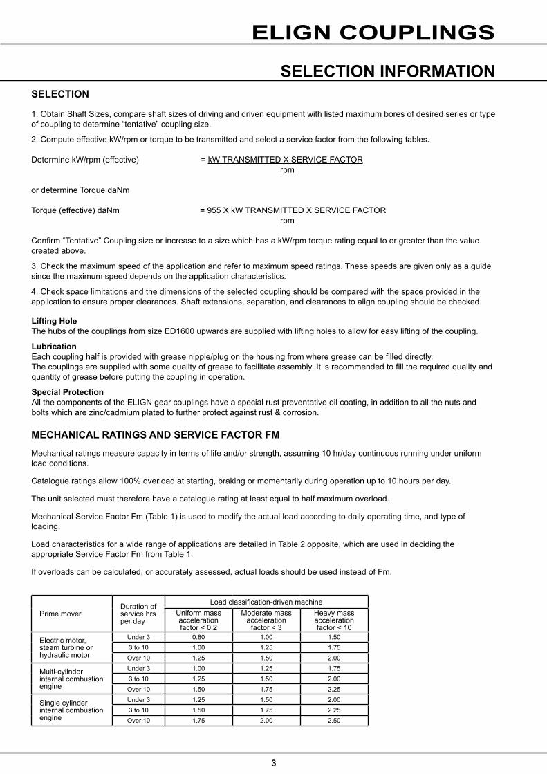
1. Obtain Shaft Sizes, compare shaft sizes of driving and driven equipment with listed maximum bores of desired series or type of coupling to determine “tentative” coupling size.
2. Compute effective kW/rpm or torque to be transmitted and select a service factor from the following tables.
Determine kW/rpm (effective) = kW TRANSMITTED X SERVICE FACTOR rpm
or determine Torque daNm
Torque (effective) daNm = 955 X kW TRANSMITTED X SERVICE FACTOR rpm
Confirm “Tentative” Coupling size or increase to a size which has a kW/rpm torque rating equal to or greater than the value created above.
3. Check the maximum speed of the application and refer to maximum speed ratings. These speeds are given only as a guide since the maximum speed depends on the application characteristics.
4. Check space limitations and the dimensions of the selected coupling should be compared with the space provided in the application to ensure proper clearances. Shaft extensions, separation, and clearances to align coupling should be checked.
Lifting HoleThe hubs of the couplings from size ED1600 upwards are supplied with lifting holes to allow for easy lifting of the coupling.
LubricationEach coupling half is provided with grease nipple/plug on the housing from where grease can be filled directly.The couplings are supplied with some quality of grease to facilitate assembly. It is recommended to fill the required quality and quantity of grease before putting the coupling in operation.
Special ProtectionAll the components of the ELIGN gear couplings have a special rust preventative oil coating, in addition to all the nuts and bolts which are zinc/cadmium plated to further protect against rust & corrosion.
SELECTION INFORMATION
Prime moverDuration of service hrs per day
Load classification-driven machineUniform mass accelerationfactor < 0.2
Moderate mass acceleration
factor < 3
Heavy mass accelerationfactor < 10
Electric motor, steam turbine or hydraulic motor
Under 3 0.80 1.00 1.503 to 10 1.00 1.25 1.75Over 10 1.25 1.50 2.00
Multi-cylinder internal combustion engine
Under 3 1.00 1.25 1.753 to 10 1.25 1.50 2.00Over 10 1.50 1.75 2.25
Single cylinder internal combustion engine
Under 3 1.25 1.50 2.003 to 10 1.50 1.75 2.25Over 10 1.75 2.00 2.50
MECHANICAL RATINGS AND SERVICE FACTOR FM
Mechanical ratings measure capacity in terms of life and/or strength, assuming 10 hr/day continuous running under uniform load conditions.
Catalogue ratings allow 100% overload at starting, braking or momentarily during operation up to 10 hours per day.
The unit selected must therefore have a catalogue rating at least equal to half maximum overload.
Mechanical Service Factor Fm (Table 1) is used to modify the actual load according to daily operating time, and type of loading.
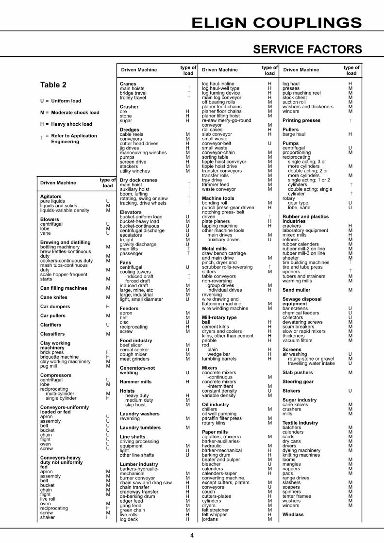
Load characteristics for a wide range of applications are detailed in Table 2 opposite, which are used in deciding the appropriate Service Factor Fm from Table 1.
If overloads can be calculated, or accurately assessed, actual loads should be used instead of Fm.
3

3
ELIGN COUPLINGS
SELECTION
1. Obtain Shaft Sizes, compare shaft sizes of driving and driven equipment with listed maximum bores of desired series or type of coupling to determine “tentative” coupling size.
2. Compute effective kW/rpm or torque to be transmitted and select a service factor from the following tables.
Determine kW/rpm (effective) = kW TRANSMITTED X SERVICE FACTOR rpm
or determine Torque daNm
Torque (effective) daNm = 955 X kW TRANSMITTED X SERVICE FACTOR rpm
Confirm “Tentative” Coupling size or increase to a size which has a kW/rpm torque rating equal to or greater than the value created above.
3. Check the maximum speed of the application and refer to maximum speed ratings. These speeds are given only as a guide since the maximum speed depends on the application characteristics.
4. Check space limitations and the dimensions of the selected coupling should be compared with the space provided in the application to ensure proper clearances. Shaft extensions, separation, and clearances to align coupling should be checked.
Lifting HoleThe hubs of the couplings from size ED1600 upwards are supplied with lifting holes to allow for easy lifting of the coupling.
LubricationEach coupling half is provided with grease nipple/plug on the housing from where grease can be filled directly.The couplings are supplied with some quality of grease to facilitate assembly. It is recommended to fill the required quality and quantity of grease before putting the coupling in operation.
Special ProtectionAll the components of the ELIGN gear couplings have a special rust preventative oil coating, in addition to all the nuts and bolts which are zinc/cadmium plated to further protect against rust & corrosion.
SELECTION INFORMATION
Prime moverDuration of service hrs per day
Load classification-driven machineUniform mass accelerationfactor < 0.2
Moderate mass acceleration
factor < 3
Heavy mass accelerationfactor < 10
Electric motor, steam turbine or hydraulic motor
Under 3 0.80 1.00 1.503 to 10 1.00 1.25 1.75Over 10 1.25 1.50 2.00
Multi-cylinder internal combustion engine
Under 3 1.00 1.25 1.753 to 10 1.25 1.50 2.00Over 10 1.50 1.75 2.25
Single cylinder internal combustion engine
Under 3 1.25 1.50 2.003 to 10 1.50 1.75 2.25Over 10 1.75 2.00 2.50
MECHANICAL RATINGS AND SERVICE FACTOR FM
Mechanical ratings measure capacity in terms of life and/or strength, assuming 10 hr/day continuous running under uniform load conditions.
Catalogue ratings allow 100% overload at starting, braking or momentarily during operation up to 10 hours per day.
The unit selected must therefore have a catalogue rating at least equal to half maximum overload.
Mechanical Service Factor Fm (Table 1) is used to modify the actual load according to daily operating time, and type of loading.
Load characteristics for a wide range of applications are detailed in Table 2 opposite, which are used in deciding the appropriate Service Factor Fm from Table 1.
If overloads can be calculated, or accurately assessed, actual loads should be used instead of Fm.
3
4
ELIGN COUPLINGS
log haul Hpresses Mpulp machine reel Mstock chest Msuction roll Mwashers and thickeners Mwinders M
Printing presses
Pullers barge haul H
Pumpscentrifugal Uproportioning Mreciprocating single acting; 3 or more cylinders M double acting; 2 or more cylinders M single acting; 1 or 2 cylinders double acting; single cylinderrotary gear type U lobe, vane U
Rubber and plastics industriescrackers Hlaboratory equipment Mmixed mills Hrefiners Mrubber calenders Mrubber mill-2 on line Mrubber mill-3 on line Msheeter Mtire building machines tire and tube pressopeners tubers and strainers Mwarming mills M
Sand muller M
Sewage disposalequipment bar screens Uchemical feeders Ucollectors Udewatering screws Mscum breakers Mslow or rapid mixers Mthickeners Mvacuum filters M
Screensair washing U rotary-stone or gravel M travelling water intake U
Slab pushers M
Steering gear
Stokers U
Sugar industrycane knives Mcrushers Mmills M
Textile industrybatchers Mcalenders Mcards Mdry cans Mdryers Mdyeing machinery Mknitting machines looms Mmangles Mnappers Mpads Mrange drives slashers Msoapers Mspinners Mtenter frames Mwashers Mwinders M
Windlass
Cranesmain hoists bridge travel trolley travel
Crusher ore Hstone Hsugar H
Dredges cable reels Mconveyors Mcutter head drives Hjig drives Hmanoeuvring winches Mpumps Mscreen drive Hstackers Mutility winches M
Dry dock cranes main hoist auxiliary hoist boom, luffing rotating, swing or slew tracking, drive wheels
Elevatorsbucket-uniform load Ubucket-heavy load Mbucket-continuous Ucentrifugal discharge Uescalators Ufreight Mgravity discharge Uman lifts passenger
Fans centrifugal Ucooling towers induced draft forced draft induced draft Mlarge, mine, etc Mlarge, industrial Mlight, small diameter U
Feedersapron Mbelt Mdisc Ureciprocating Hscrew M
Food industry beef slicer Mcereal cooker Udough mixer Mmeat grinders M
Generators-not welding U
Hammer mills H
Hoists heavy duty H medium duty M skip hoist M
Laundry washersreversing M
Laundry tumblers M
Line shaftsdriving processing equipment Mlight Uother line shafts U
Lumber industrybarkers-hydraulic-mechanical Mburner conveyor Mchain saw and drag saw Hchain transfer Hcraneway transfer Hde-barking drum Hedger feed Mgang feed Mgreen chain Mlive rolls Hlog deck H
Agitatorspure liquids Uliquids and solids Mliquids-variable density M
Blowerscentrifugal Ulobe Mvane U
Brewing and distillingbottling machinery Mbrew kettles-continuous duty Mcookers-continuous duty Mmash tubs-continuous duty Mscale hopper-frequent starts M
Can filling machines M
Cane knifes M
Car dumpers H
Car pullers M
Clarifiers U
Classifiers M
Clay working machinery brick press Hbriquette machine Hclay working machinery Mpug mill M
Compressors centrifugal Ulobe Mreciprocating multi-cylinder M single cylinder H
Conveyors-uniformly loaded or fedapron Uassembly Ubelt Ubucket Uchain Uflight Uoven Uscrew U
Conveyors-heavy duty not uniformly fedapron Massembly Mbelt Mbucket Mchain Mflight Mlive rolloven Mreciprocating Hscrew Mshaker H
type ofloadDriven Machine
log haul-incline Hlog haul-well type Hlog turning device Hmain log conveyor Hoff bearing rolls Mplaner feed chains Mplaner floor chains Mplaner tilting hoist Mre-saw merry-go-roundconveyor Mroll cases Hslab conveyor Hsmall waste conveyor-belt Usmall waste conveyor-chain Msorting table Mtipple hoist conveyor Mtipple hoist drive Mtransfer conveyors Mtransfer rolls Mtray drive Mtrimmer feed Mwaste conveyor M
Machine tools bending roll Mpunch press-gear driven Hnotching press- beltdrivenplate planers Htapping machine Hother machine tools main drives M auxiliary drives U
Metal millsdraw bench carriage and main drive Mpinch, dryer and scrubber rolls-reversing slitters Mtable conveyorsnon-reversing group drives M individual drives Hreversing wire drawing and flattening machine Mwire winding machine M
Mill-rotary typeball Hcement kilns Hdryers and coolers Hkilns, other than cement Hpebble Hrod plain H wedge bar Htumbling barrels H
Mixers concrete mixers -continuous Mconcrete mixers -intermittent Mconstant density Uvariable density M
Oil industrychillers Moil well pumping paraffin filter press Mrotary kilns M
Paper millsagitators, (mixers) Mbarker-auxiliaries-hydraulic Mbarker-mechanical Hbarking drum Hbeater and pulper Mbleacher Ucalenders Mcalenders-super Hconverting machine,except cutters, platers Mconveyors Ucouch Mcutters-plates Hcylinders Mdryers Mfelt stretcher Mfelt whipper Hjordans M
Driven Machine Driven Machine Driven Machinetype ofload
type ofload
type ofload
Table 2
U = Uniform load
M = Moderate shock load
H = Heavy shock load
= Refer to Application Engineering
SERVICE FACTORS
4
ELIGN COUPLINGS
6
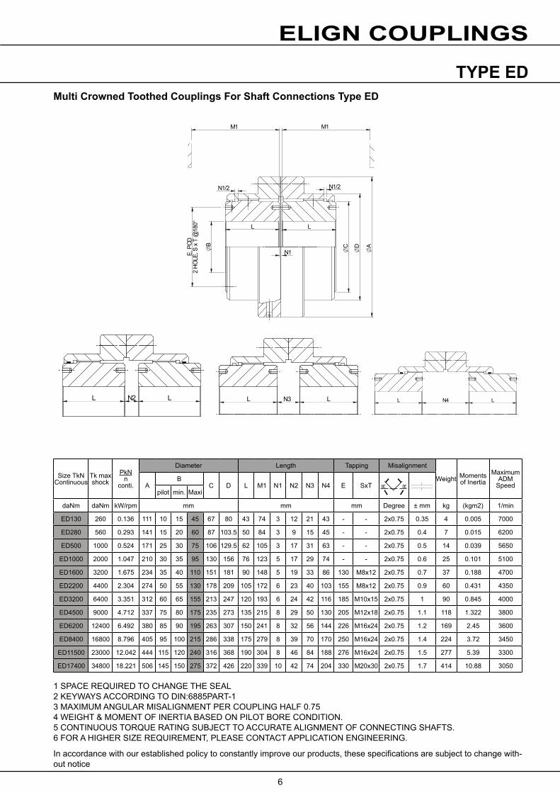
TYPE ED
1 SPACE REQUIRED TO CHANGE THE SEAL2 KEYWAYS ACCORDING TO DIN:6885PART-13 MAXIMUM ANGULAR MISALIGNMENT PER COUPLING HALF 0.754 WEIGHT & MOMENT OF INERTIA BASED ON PILOT BORE CONDITION.5 CONTINUOUS TORQUE RATING SUBJECT TO ACCURATE ALIGNMENT OF CONNECTING SHAFTS.6 FOR A HIGHER SIZE REQUIREMENT, PLEASE CONTACT APPLICATION ENGINEERING.
In accordance with our established policy to constantly improve our products, these specifications are subject to change with-out notice
Multi Crowned Toothed Couplings For Shaft Connections Type ED
Size TkN Continuous
Tk max shock
PkNn
conti.
Diameter Length Tapping Misalignment
Weight Moments of Inertia
Maximum ADM
SpeedAB
C D L M1 N1 N2 N3 N4 E SxTpilot min. Maxi
daNm daNm kW/rpm mm mm mm Degree ± mm kg (kgm2) 1/min
ED130 260 0.136 111 10 15 45 67 80 43 74 3 12 21 43 - - 2x0.75 0.35 4 0.005 7000
ED280 560 0.293 141 15 20 60 87 103.5 50 84 3 9 15 45 - - 2x0.75 0.4 7 0.015 6200
ED500 1000 0.524 171 25 30 75 106 129.5 62 105 3 17 31 63 - - 2x0.75 0.5 14 0.039 5650
ED1000 2000 1.047 210 30 35 95 130 156 76 123 5 17 29 74 - - 2x0.75 0.6 25 0.101 5100
ED1600 3200 1.675 234 35 40 110 151 181 90 148 5 19 33 86 130 M8x12 2x0.75 0.7 37 0.188 4700
ED2200 4400 2.304 274 50 55 130 178 209 105 172 6 23 40 103 155 M8x12 2x0.75 0.9 60 0.431 4350
ED3200 6400 3.351 312 60 65 155 213 247 120 193 6 24 42 116 185 M10x15 2x0.75 1 90 0.845 4000
ED4500 9000 4.712 337 75 80 175 235 273 135 215 8 29 50 130 205 M12x18 2x0.75 1.1 118 1.322 3800
ED6200 12400 6.492 380 85 90 195 263 307 150 241 8 32 56 144 226 M16x24 2x0.75 1.2 169 2.45 3600
ED8400 16800 8.796 405 95 100 215 286 338 175 279 8 39 70 170 250 M16x24 2x0.75 1.4 224 3.72 3450
ED11500 23000 12.042 444 115 120 240 316 368 190 304 8 46 84 188 276 M16x24 2x0.75 1.5 277 5.39 3300
ED17400 34800 18.221 506 145 150 275 372 426 220 339 10 42 74 204 330 M20x30 2x0.75 1.7 414 10.88 3050
L L
N1 OC
OD
OA
N1/2 N1/2
M1 M1
E, P
CD2
HOLE
, S x
T @
180°
OB
L N2 L L N3 L L N4 L
R R

ELIGN COUPLINGS
7
TYPE ED (SUPER SERIES)
L L
N1
G G
M1 M1
OD
OC
OA
E, P
CD2
HOLE
S, S
x T
OB
1. SPACE REQUIRED TO CHANGE THE SEAL2. KEYWAYS ACCORDING TO DIN:6885 PART-13. MAXIMUM ANGULAR MISALIGNMENT PER COUPLING HALF 0.754. WEIGHT & MOMENT OF INERTIA BASED ON PILOT BORE CONDITION.5. CONTINUOUS TORQUE RATING SUBJECT TO ACCURATE ALIGNMENT OF CONNECTING SHAFTS.6. FOR A HIGHER SIZE REQUIREMENT, PLEASE CONTACT APPLICATION ENGINEERING.7. FOR MARKED DIMENSIONS, PLEASE CONTACT APPLICATION ENGINEERING.
In accordance with our established policy to constantly improve our products, these specifications are subject to change with-out notice.
Multi Crowned Toothed Couplings For Shaft Connections Type ED (SUPER SERIES)
Size TkN Continuous
Tk max shock
PkNn
conti.
Diameter Length Tapping MisalignmentWeight
kgMoments of Inertia(kgm2)
Maximum ADM
Speed1/minA
BC D L M1 N1 N2 N3 N4 E SxT
pilot min. Maxi
daNm daNm kW/rpm mm mm degree ± mm kg (kgm2) 1/min
ED 25200 50400 26.39 632 155 160 310 422 550 280 10 15 119 223 346 360 M20x30 2x0.75 1.8 670 26.75 1830
ED 29000 58000 30.366 640 195 200 320 432 518 292 6.5 13 33 53 255 380 M20x30 2x0.75 2.1 760 31 1800
ED 37000 74000 38.746 715 205 210 355 472 616 310 12 20 133 246 383 410 M24x40 2x0.75 2.2 930 48 1460
ED 45000 90000 47.123 750 225 230 370 502 648 330 11.5 20 144 268 408 435 M24x40 2x0.75 2.2 1110 65.8 1395
ED 56000 112000 58.639 804 275 280 450 594 682 350 6.5 13 61 109 335 544 M24x40 2x0.75 2.7 1532 105 1300
ED 75000 150000 78.539 910 285 290 480 620 812 410 10.5 25 121 217 * 550 M36x55 2x0.75 3 2180 198 1000
ED 90000 180000 94.247 980 315 320 515 670 860 430 15.5 25 102 179 * 585 M36x55 2x0.75 3 2520 265 940
ED 110000 220000 115.19 1020 325 330 540 700 908 450 16 25 97 169 * 615 M36x55 2x0.75 4 2910 333 900
L N2 L L N3 L L N4 L
ARRANGEMENT FOR ED- 75000 AND ONWARDS
R R

ELIGN COUPLINGS
8
TYPE ER
1 SPACE REQUIRED TO CHANGE THE SEAL2 KEYWAYS ACCORDING TO DIN:6885 PART-13 MAXIMUM ANGULAR MISALIGNMENT 0.754 WEIGHT & MOMENT OF INERTIA BASED ON PILOT BORE CONDITION.5 CONTINUOUS TORQUE RATING SUBJECT TO ACCURATE ALIGNMENT OF CONNECTING SHAFTS.6 FOR A HIGHER SIZE REQUIREMENT, PLEASE CONTACT APPLICATION ENGINEERING..
In accordance with our established policy to constantly improve our products, these specifications are subject to change with-out notice.
Multi Crowned Toothed Couplings For Shaft Connections Type ER
Size TkN Continuous
Tk max shock
PkNn
conti.
Diameter Length Tapping
WeightMoments
of Inertia
Maximum ADM
SpeedAB B1
C D D1 L L1 M1 N1 E E1 SxTpilot min. Maxi pilot min. Maxi
daNm daNm kW/rpm mm mm mm degree Kg j (kgm2) 1/min
ER 130 260 0.136 111 10 15 45 10 15 55 67 80 80 43 40 74 5 - - - 0.75 4 0.005 7000
ER 280 560 0.293 141 15 20 60 15 20 75 87 103.5 103.5 50 47 84 5 - - - 0.75 8 0.015 6200
ER 500 1000 0.524 171 25 30 75 25 30 95 106 129.5 126 62 58 105 5 - - - 0.75 14 0.039 5650
ER 1000 2000 1.047 210 30 35 95 30 35 110 130 156 152 76 74 123 6 - - - 0.75 26 0.102 5100
ER 1600 3200 1.675 234 35 40 110 35 40 130 151 181 178 90 87 148 6 130 155 M8x12 0.75 38 0.196 4700
ER 2200 4400 2.304 274 50 55 130 50 55 155 178 209 208 105 101 172 6.5 155 180 M8x12 0.75 61 0.45 4350
ER 3200 6400 3.351 312 60 65 155 60 65 180 213 247 245 120 113 193 6.5 185 210 M10x15 0.75 91 0.871 4000
ER 4500 9000 4.712 337 75 80 175 75 80 200 235 273 270 135 129 215 8 205 235 M12x18 0.75 120 1.368 3800
ER 6200 12400 6.492 380 85 90 195 85 90 230 263 307 305 150 150 241 8 226 265 M16x24 0.75 175 2.586 3600
ER 8400 16800 8.796 405 95 100 215 95 100 250 286 338 330 175 175 279 8 250 290 M16x24 0.75 232 3.91 3450
ER 11500 23000 12.042 444 115 120 240 115 120 280 316 368 362 190 190 304 10 276 320 M16x24 0.75 287 5.655 3300
ER 17400 34800 18.221 506 145 150 275 145 150 330 372 426 416 220 220 339 13 330 370 M20x30 0.75 430 11.5 3050
OB
L L
OD
OA
OB1OC
N1E, P
CD2
HOLE
, S x
T @
180°
E1, P
CD2
HOLE
, S x
T
OD1
R
R
ELIGN COUPLINGS
9
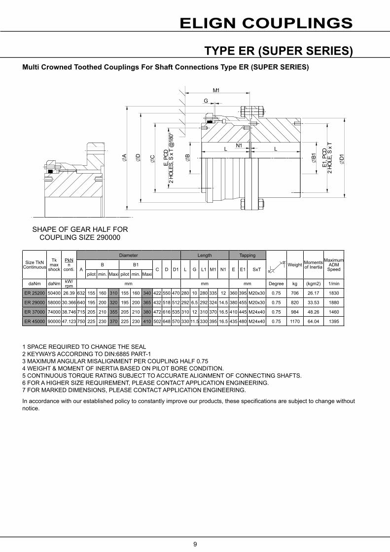
TYPE ER (SUPER SERIES)
1 SPACE REQUIRED TO CHANGE THE SEAL2 KEYWAYS ACCORDING TO DIN:6885 PART-13 MAXIMUM ANGULAR MISALIGNMENT PER COUPLING HALF 0.754 WEIGHT & MOMENT OF INERTIA BASED ON PILOT BORE CONDITION.5 CONTINUOUS TORQUE RATING SUBJECT TO ACCURATE ALIGNMENT OF CONNECTING SHAFTS.6 FOR A HIGHER SIZE REQUIREMENT, PLEASE CONTACT APPLICATION ENGINEERING.7 FOR MARKED DIMENSIONS, PLEASE CONTACT APPLICATION ENGINEERING.
In accordance with our established policy to constantly improve our products, these specifications are subject to change without notice.
Multi Crowned Toothed Couplings For Shaft Connections Type ER (SUPER SERIES)
Size TkN Continuous
Tk max
shock
PkNn
conti.
Diameter Length Tapping
Weight Moments of Inertia
Maximum ADM
SpeedAB B1
C D D1 L G L1 M1 N1 E E1 SxTpilot min. Maxi pilot min. Maxi
daNm daNm kW/rpm mm mm mm Degree kg (kgm2) 1/min
ER 25200 50400 26.39 632 155 160 310 155 160 340 422 550 470 280 10 280 335 12 360 395 M20x30 0.75 706 26.17 1830
ER 29000 58000 30.366 640 195 200 320 195 200 365 432 518 512 292 6.5 292 324 14.5 380 455 M20x30 0.75 820 33.53 1880
ER 37000 74000 38.746 715 205 210 355 205 210 380 472 616 535 310 12 310 370 16.5 410 445 M24x40 0.75 984 48.26 1460
ER 45000 90000 47.123 750 225 230 370 225 230 410 502 648 570 330 11.5 330 395 16.5 435 480 M24x40 0.75 1170 64.04 1395
L LN1O
C
OD1
G
M1
OD
OA
OB
E, P
CD2
HOLE
S, S
x T
@18
0°
OB1
E1, P
CD2
HOLE
, S x
T
SHAPE OF GEAR HALF FORCOUPLING SIZE 290000
R
R
ELIGN COUPLINGS
10
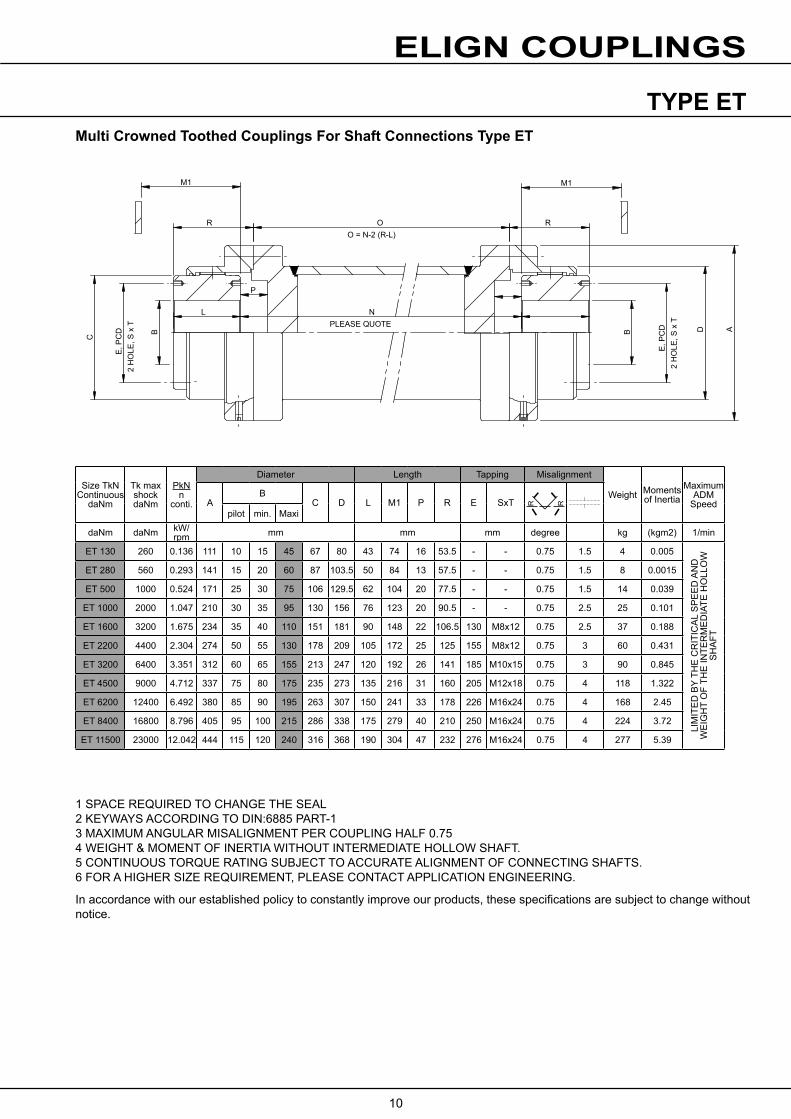
TYPE ET
1 SPACE REQUIRED TO CHANGE THE SEAL2 KEYWAYS ACCORDING TO DIN:6885 PART-13 MAXIMUM ANGULAR MISALIGNMENT PER COUPLING HALF 0.754 WEIGHT & MOMENT OF INERTIA WITHOUT INTERMEDIATE HOLLOW SHAFT.5 CONTINUOUS TORQUE RATING SUBJECT TO ACCURATE ALIGNMENT OF CONNECTING SHAFTS.6 FOR A HIGHER SIZE REQUIREMENT, PLEASE CONTACT APPLICATION ENGINEERING.
In accordance with our established policy to constantly improve our products, these specifications are subject to change without notice.
Multi Crowned Toothed Couplings For Shaft Connections Type ET
Size TkN Continuous
daNm
Tk max shockdaNm
PkNn
conti.
Diameter Length Tapping Misalignment
Weight Moments of Inertia
Maximum ADM
SpeedAB
C D L M1 P R E SxTpilot min. Maxi
daNm daNm kW/rpm mm mm mm degree kg (kgm2) 1/min
ET 130 260 0.136 111 10 15 45 67 80 43 74 16 53.5 - - 0.75 1.5 4 0.005
LIM
ITE
D B
Y TH
E C
RIT
ICA
L S
PE
ED
AN
D
WE
IGH
T O
F TH
E IN
TER
ME
DIA
TE H
OLL
OW
S
HA
FT
ET 280 560 0.293 141 15 20 60 87 103.5 50 84 13 57.5 - - 0.75 1.5 8 0.0015
ET 500 1000 0.524 171 25 30 75 106 129.5 62 104 20 77.5 - - 0.75 1.5 14 0.039
ET 1000 2000 1.047 210 30 35 95 130 156 76 123 20 90.5 - - 0.75 2.5 25 0.101
ET 1600 3200 1.675 234 35 40 110 151 181 90 148 22 106.5 130 M8x12 0.75 2.5 37 0.188
ET 2200 4400 2.304 274 50 55 130 178 209 105 172 25 125 155 M8x12 0.75 3 60 0.431
ET 3200 6400 3.351 312 60 65 155 213 247 120 192 26 141 185 M10x15 0.75 3 90 0.845
ET 4500 9000 4.712 337 75 80 175 235 273 135 216 31 160 205 M12x18 0.75 4 118 1.322
ET 6200 12400 6.492 380 85 90 195 263 307 150 241 33 178 226 M16x24 0.75 4 168 2.45
ET 8400 16800 8.796 405 95 100 215 286 338 175 279 40 210 250 M16x24 0.75 4 224 3.72
ET 11500 23000 12.042 444 115 120 240 316 368 190 304 47 232 276 M16x24 0.75 4 277 5.39
L
P
NPLEASE QUOTE
R
M1 M1
E, P
CD
2 H
OLE
, S x
T
C
AB B D
OO = N-2 (R-L)
R
E, P
CD
2 H
OLE
, S x
T
R R
ELIGN COUPLINGS
11
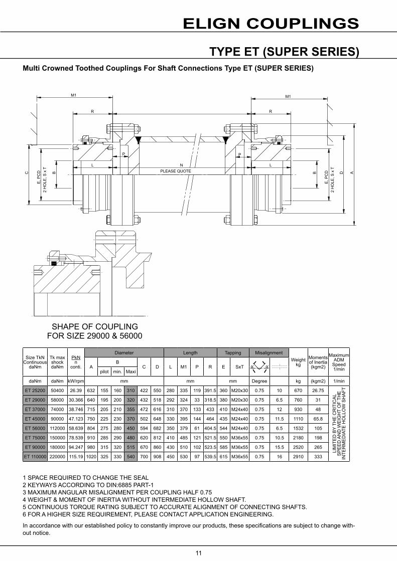
TYPE ET (SUPER SERIES)
1 SPACE REQUIRED TO CHANGE THE SEAL2 KEYWAYS ACCORDING TO DIN:6885 PART-13 MAXIMUM ANGULAR MISALIGNMENT PER COUPLING HALF 0.754 WEIGHT & MOMENT OF INERTIA WITHOUT INTERMEDIATE HOLLOW SHAFT.5 CONTINUOUS TORQUE RATING SUBJECT TO ACCURATE ALIGNMENT OF CONNECTING SHAFTS.6 FOR A HIGHER SIZE REQUIREMENT, PLEASE CONTACT APPLICATION ENGINEERING.
In accordance with our established policy to constantly improve our products, these specifications are subject to change with-out notice.
Multi Crowned Toothed Couplings For Shaft Connections Type ET (SUPER SERIES)
Size TkN Continuous
daNm
Tk max shockdaNm
PkNn
conti.
Diameter Length Tapping MisalignmentWeight
kgMoments of Inertia(kgm2)
Maximum ADM
Speed1/minA
BC D L M1 P R E SxT
pilot min. Maxi
daNm daNm kW/rpm mm mm mm Degree kg (kgm2) 1/min
ET 25200 50400 26.39 632 155 160 310 422 550 280 335 119 391.5 360 M20x30 0.75 10 670 26.75
LIM
ITE
D B
Y TH
E C
RIT
ICA
L S
PE
ED
AN
D W
EIG
HT
OF
THE
IN
TER
ME
DIA
TE H
OLL
OW
SH
AFT
ET 29000 58000 30.366 640 195 200 320 432 518 292 324 33 318.5 380 M20x30 0.75 6.5 760 31
ET 37000 74000 38.746 715 205 210 355 472 616 310 370 133 433 410 M24x40 0.75 12 930 48
ET 45000 90000 47.123 750 225 230 370 502 648 330 395 144 464 435 M24x40 0.75 11.5 1110 65.8
ET 56000 112000 58.639 804 275 280 450 594 682 350 379 61 404.5 544 M24x40 0.75 6.5 1532 105
ET 75000 150000 78.539 910 285 290 480 620 812 410 485 121 521.5 550 M36x55 0.75 10.5 2180 198
ET 90000 180000 94.247 980 315 320 515 670 860 430 510 102 523.5 585 M36x55 0.75 15.5 2520 265
ET 110000 220000 115.19 1020 325 330 540 700 908 450 530 97 539.5 615 M36x55 0.75 16 2910 333
M1
R R
L NPLEASE QUOTE
L
P P
C B B D A
M1
E, P
CD
2 H
OLE
, S x
T
E, P
CD
2 H
OLE
, S x
TSHAPE OF COUPLING
FOR SIZE 29000 & 56000
R R

ELIGN COUPLINGS
12
TYPE EV
1 SPACE REQUIRED TO CHANGE THE SEAL2 KEYWAYS ACCORDING TO DIN:6885 PART-13 MAXIMUM ANGULAR MISALIGNMENT PER COUPLING HALF 0.754 WEIGHT & MOMENT OF INERTIA BASED ON PILOT BORE CONDITION.5 CONTINUOUS TORQUE RATING SUBJECT TO ACCURATE ALIGNMENT OF CONNECTING SHAFTS.* MAXIMUM ANGULAR MISALIGNMENT PER COUPLING HALF 0.56 FOR A HIGHER SIZE REQUIREMENT, PLEASE CONTACT APPLICATION ENGINEERING.
In accordance with our established policy to constantly improve our products, these specifications are subject to change with-out notice.
Multi Crowned Toothed Couplings For Shaft Connections Type EV
Size TkN Continuous
Tk max shock
PkNn
conti.
Diameter Length Tapping Misalignment
Weight Moments of Inertia
Maximum ADM
SpeedAB
C D L M1 N N1 N2 E SxTpilot min. Maxi
daNm daNm kW/rpm mm mm mm kg (kgm2) 1/min
EV 130 260 0.136 111 10 15 45 67 80 43 74 8 1.5 5.5 - - 2x0.75 0.35 4.5 0.0057 5000
EV 280 560 0.293 141 15 20 60 87 103.5 50 84 5 1.5 5.5 - - 2X0.75 0.4 8.5 0.017 4400
EV 500 1000 0.524 171 25 30 75 106 129.5 62 105 12.5 1.5 6 - - 2X0.75 0.5 15 0.043 4000
EV 1000 2000 1.047 210 30 35 95 130 156 76 123 11 2.5 8.5 - - 2X0.75 0.6 26 0.11 3600
EV 1600 3200 1.675 234 35 40 110 151 181 90 148 13 2.5 8.5 130 M8X12 2X0.75 0.7 39 0.206 3350
EV 2200 4400 2.304 274 50 55 130 178 209 105 172 14 3 12 155 M8X12 2X0.75 0.9 61 0.461 3100
EV 3200 6400 3.351 312 60 65 155 213 247 120 193 15 3 12 185 M10X15 2X0.75 1 93 0.935 2800
EV 4500 9000 4.712 337 75 80 175 235 273 135 215 17 4 16 205 M12X18 2X0.75 1.1 122 1.454 2700
EV 6200 12400 6.492 380 85 90 195 263 307 150 241 20 4 16 226 M16X24 2X0.75 1.2 175 2.71 2550
EV 8400 16800 8.796 405 95 100 215 286 338 175 279 27 4 16 250 M16X24 2X0.5* 0.9 236 4.32 2450
EV 11500 23000 12.042 444 115 120 240 316 368 190 304 34 4 16 276 M16X24 2X0.5* 1 295 6.48 2300
EV 17400 34800 18.221 506 145 150 275 372 426 220 339 28 5 20 330 M20X30 2X0.5* 1.1 430 11 2150
TOP SIDE
BOTTOM SIDE
OA
OD
OC
L
N
N1
L
N1N2
M1
M1
E, PCD2 HOLE, S x T @180°
OBR R
ELIGN COUPLINGS
13
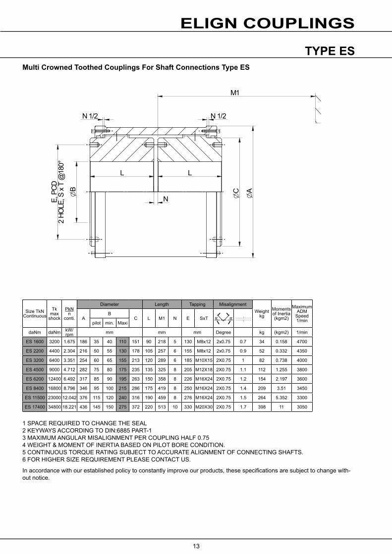
TYPE ES
1 SPACE REQUIRED TO CHANGE THE SEAL2 KEYWAYS ACCORDING TO DIN:6885 PART-13 MAXIMUM ANGULAR MISALIGNMENT PER COUPLING HALF 0.754 WEIGHT & MOMENT OF INERTIA BASED ON PILOT BORE CONDITION.5 CONTINUOUS TORQUE RATING SUBJECT TO ACCURATE ALIGNMENT OF CONNECTING SHAFTS.6 FOR HIGHER SIZE REQUIREMENT PLEASE CONTACT US.
In accordance with our established policy to constantly improve our products, these specifications are subject to change with-out notice.
Multi Crowned Toothed Couplings For Shaft Connections Type ES
Size TkN Continuous
Tk max
shock
PkNn
conti.
Diameter Length Tapping MisalignmentWeight
kgMoments of Inertia(kgm2)
Maximum ADM
Speed1/minA
BC L M1 N E SxT
pilot min. Maxi
daNm daNm kW/rpm mm mm mm Degree kg (kgm2) 1/min
ES 1600 3200 1.675 186 35 40 110 151 90 218 5 130 M8x12 2x0.75 0.7 34 0.158 4700
ES 2200 4400 2.304 216 50 55 130 178 105 257 6 155 M8x12 2x0.75 0.9 52 0.332 4350
ES 3200 6400 3.351 254 60 65 155 213 120 289 6 185 M10X15 2X0.75 1 82 0.738 4000
ES 4500 9000 4.712 282 75 80 175 235 135 325 8 205 M12X18 2X0.75 1.1 112 1.255 3800
ES 6200 12400 6.492 317 85 90 195 263 150 358 8 226 M16X24 2X0.75 1.2 154 2.197 3600
ES 8400 16800 8.796 346 95 100 215 286 175 419 8 250 M16X24 2X0.75 1.4 209 3.51 3450
ES 11500 23000 12.042 376 115 120 240 316 190 459 8 276 M16X24 2X0.75 1.5 264 5.352 3300
ES 17400 34800 18.221 436 145 150 275 372 220 513 10 330 M20X30 2X0.75 1.7 398 11 3050
M1
N 1/2N 1/2
E, P
CD2
HOLE
, S x
T @
180°
OA
OC
N
L L
OB
R R

www.benzlers.com
www.radicon.com
AUSTRALIA
Radicon Transmission (Australia) PTY Ltd
AustraliaTel: +61 421 822 315
EUROPE
Benzler TBA BVJachthavenweg 2 NL-5928 NT Venlo
GermanyTel: 0800 350 40 00Fax: 0800 350 40 01
ItalyTel: +39 02 824 3511
Netherlands & the rest of EuropeTel: +31 77 324 59 00Fax: +31 77 324 59 01
INDIA
Elecon. Engineering Company Ltd.Anand Sojitra RoadVallabh Vidyanagar388120 GujaratIndia
Tel: +91 2692 236513
DENMARK
Benzler Transmission A/SDalager 1DK-2605 Brøndby, Denmark
Tel: +45 36 34 03 00Fax: +45 36 77 02 42
FINLAND
Oy Benzler ABVanha Talvitie 3CFI-00580 Helsingfors, Finland
Tel: +358 9 340 1716Fax: +358 10 296 2072
SWEDEN & NORWAY
AB BenzlersPorfyrgatan254 68 HelsingborgSweden
Tel: +46 42 18 68 00Fax: +46 42 21 88 03
THAILAND
Radicon Transmission (Thailand) Ltd700/43 Moo 6Amata Nakorn Industrial EstateTumbol KlongtumruMuang, Chonburi 20000Thailand
Tel: +66 3845 9044Fax: +66 3821 3655
UNITED KINGDOM
Radicon Transmission UK LtdUnit J3Lowfields Business Park, Lowfields Way, EllandWest Yorkshire, HX5 9DA
Tel: +44 1484 465 800 Fax: +44 1484 465 801
USA
Radicon Drive Systems, Inc.2475 Alft Lane ElginChicagoIllinois60124USA
Tel: +1 847 593 9910Fax: +1 847 593 9950
CONTACT US

Benzlers
Denmark +45 36 340300Finland +358 9 3401716Germany +49 800 3504000 Italy +39 02 824 3511Sweden +46 42 186800The Netherlands +31 77 3245900www.benzlers.com
Radicon
Thailand +66 38459044 United Kingdom +44 1484 465800USA +1 847 5939910www.radicon.com