makharia.inmakharia.in/wp-content/files_mf/eligncoupling.pdf · development of a new series of...
12
ELECON ELIGN MULTI CROWNED GEAR COU- PLING
Transcript of makharia.inmakharia.in/wp-content/files_mf/eligncoupling.pdf · development of a new series of...
�������������������� �����������������
GEAR COUPLING
Ever Since its inception in 1951 Elecon's endeavour is to consultantly update the products and offersuperior products to its customers based on the latest technology available. Such a long experience inthe field of development, design and manufacture of Power Transmission Equipment has led to thedevelopment of a new series of ELIGN Gear couplings.
The ELIGN Gear couplings are manufactured in Elecon's state of the art technology manufacturingplant on precision CNC machines. The new series of Gear couplings has a technology superioritycompared with the other gear coupling available in the market. The usage of high quality material andworkmanship is built-in-feature of ELIGN Gear couplings.
WHY GEAR COUPLING ?
A Gear Coupling is used to join two rotating shafts for efficient transmission of mechanical power.Although the shafts are accurately aligned at the time of installation, it is likely that during the operationthe alignment may get disturbed due to setting of foundation, thermal expansion, shaft deflection,wearing out of other parts, improper maintenance and many more reasons. Due to this unavoidablemisalignment occurring during the operation a gear coulping provides a better solution to compensateor minimise the effect of misalignment.
The gear Couplings are therefore idealy suited for wide range of application in the entire field of drivetechnology.
MISALIGNMENT
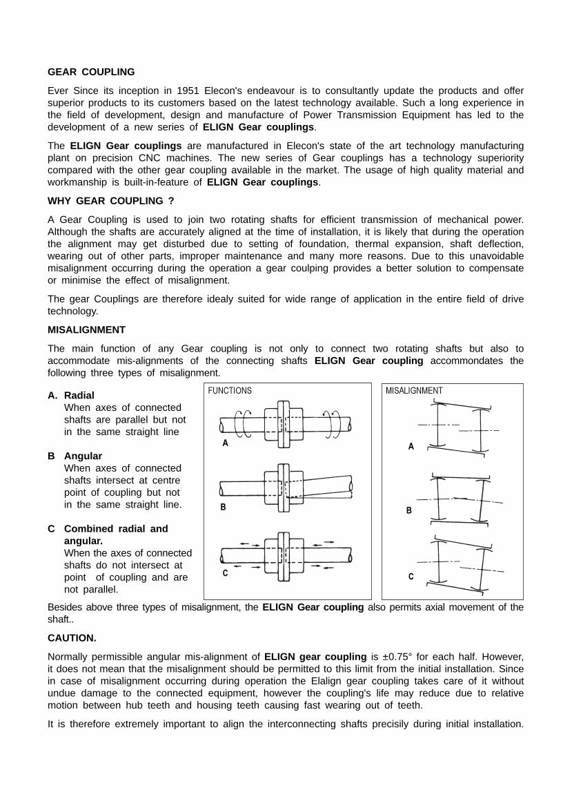
The main function of any Gear coupling is not only to connect two rotating shafts but also toaccommodate mis-alignments of the connecting shafts ELIGN Gear coupling accommondates thefollowing three types of misalignment.
Besides above three types of misalignment, the ELIGN Gear coupling also permits axial movement of theshaft..
CAUTION.
Normally permissible angular mis-alignment of ELIGN gear coupling is ±0.75° for each half. However,it does not mean that the misalignment should be permitted to this limit from the initial installation. Sincein case of misalignment occurring during operation the Elalign gear coupling takes care of it withoutundue damage to the connected equipment, however the coupling's life may reduce due to relativemotion between hub teeth and housing teeth causing fast wearing out of teeth.
It is therefore extremely important to align the interconnecting shafts precisily during initial installation.
��������� ������ ��
�
�
�
�
�
�
A. RadialWhen axes of connectedshafts are parallel but notin the same straight line
B AngularWhen axes of connectedshafts intersect at centrepoint of coupling but notin the same straight line.
C Combined radial andangular.When the axes of connectedshafts do not intersect atpoint of coupling and arenot parallel.
FEATURES OF ELIGN COUPLINGS
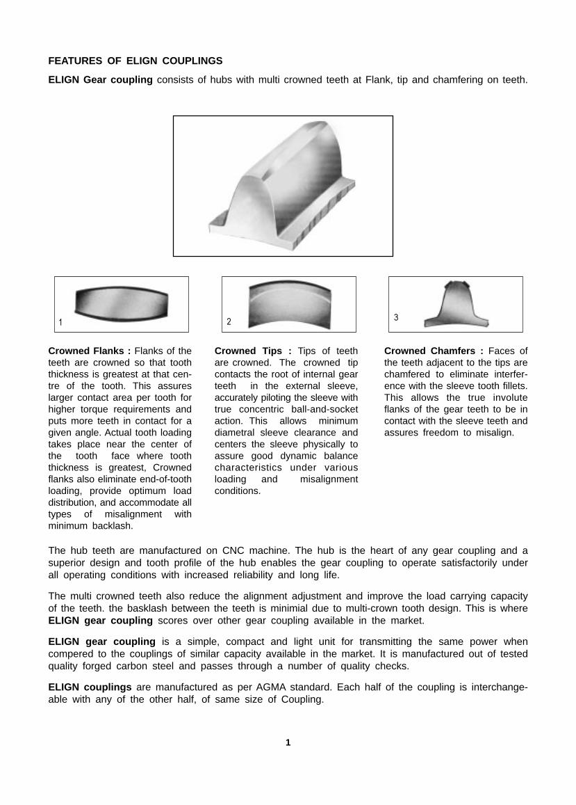
ELIGN Gear coupling consists of hubs with multi crowned teeth at Flank, tip and chamfering on teeth.
� � �
Crowned Flanks : Flanks of theteeth are crowned so that tooththickness is greatest at that cen-tre of the tooth. This assureslarger contact area per tooth forhigher torque requirements andputs more teeth in contact for agiven angle. Actual tooth loadingtakes place near the center ofthe tooth face where tooththickness is greatest, Crownedflanks also eliminate end-of-toothloading, provide optimum loaddistribution, and accommodate alltypes of misalignment withminimum backlash.
Crowned Tips : Tips of teethare crowned. The crowned tipcontacts the root of internal gearteeth in the external sleeve,accurately piloting the sleeve withtrue concentric ball-and-socketaction. This allows minimumdiametral sleeve clearance andcenters the sleeve physically toassure good dynamic balancecharacteristics under variousloading and misalignmentconditions.
Crowned Chamfers : Faces ofthe teeth adjacent to the tips arechamfered to eliminate interfer-ence with the sleeve tooth fillets.This allows the true involuteflanks of the gear teeth to be incontact with the sleeve teeth andassures freedom to misalign.
The hub teeth are manufactured on CNC machine. The hub is the heart of any gear coupling and asuperior design and tooth profile of the hub enables the gear coupling to operate satisfactorily underall operating conditions with increased reliability and long life.
The multi crowned teeth also reduce the alignment adjustment and improve the load carrying capacityof the teeth. the basklash between the teeth is minimial due to multi-crown tooth design. This is whereELIGN gear coupling scores over other gear coupling available in the market.
ELIGN gear coupling is a simple, compact and light unit for transmitting the same power whencompered to the couplings of similar capacity available in the market. It is manufactured out of testedquality forged carbon steel and passes through a number of quality checks.
ELIGN couplings are manufactured as per AGMA standard. Each half of the coupling is interchange-able with any of the other half, of same size of Coupling.
1
ORDERING INFORMATIONWHEN ORDERING, SPECIFY FOLLOWING INFORMATION
1 Quantity and delivery requirements
2 Shaft or bore sizes and keyway dimensions. Give exact dimensions with tolerances.
3 Load –– Horsepower and/or torque at a specific RPM. State normal and maximum conditions.
4 Speed –– minimum. normal and maximum.
5 Application –– type of driver and driven equipment.
6 Coupling Series, Type and Size.
7 Space limitations –– envelope dimensions, shaft extensions and shaft spacing.
8 Unusual misalignment conditions.
9 Modifications –– tapered bores, special keys, hub cut off, counterbores or others
10 Unusual operating conditions ambient temperatures and atmospheres.
SELECTION
1 Obtain Shaft Sizes Compare shaft sizes of driving and driven equipment with listed maximumbores of desired Series or Type coupling to determine "tentative" Coupling size
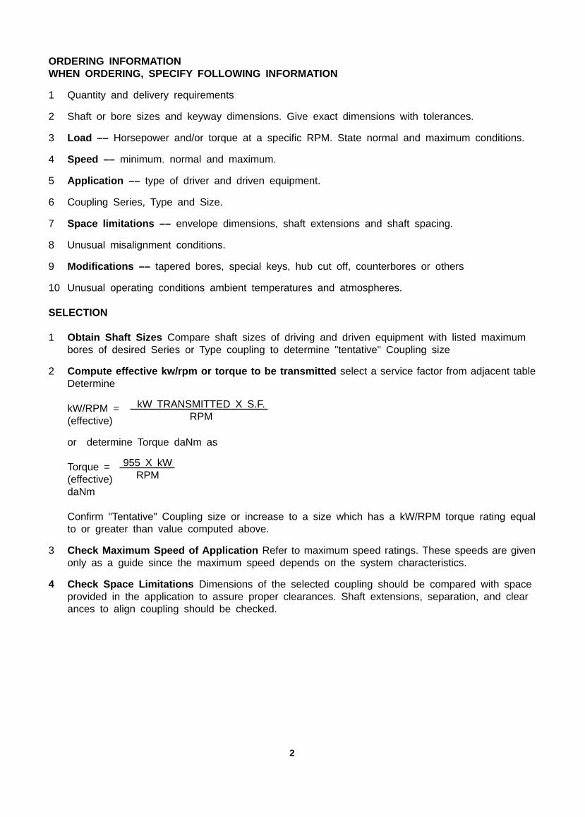
2 Compute effective kw/rpm or torque to be transmitted select a service factor from adjacent tableDetermine
kW/RPM =(effective)
or determine Torque daNm as
Torque =(effective)daNm
Confirm "Tentative" Coupling size or increase to a size which has a kW/RPM torque rating equalto or greater than value computed above.
3 Check Maximum Speed of Application Refer to maximum speed ratings. These speeds are givenonly as a guide since the maximum speed depends on the system characteristics.
4 Check Space Limitations Dimensions of the selected coupling should be compared with spaceprovided in the application to assure proper clearances. Shaft extensions, separation, and clearances to align coupling should be checked.
kW TRANSMITTED X S.F.RPM
955 X kWRPM
2
driven machines
Dailyduty (h)
8 16 24
Factor of driven machineDaily
duty (h)
8 16 24
Dailyduty (h)
8 16 24driven machines driven machines
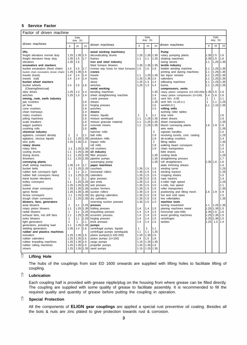
wood working machinerydecoraticating drums 1.25 1.35 1.35frames 1.1 1.1 1.25iron and steel industryblast fumace blowers 1.35 1.35 1.35inclined skip hoists for blast furnaces 1.5 1.5 1.6cranestravels 1.1 1.25 1.35hoists 1.25 1.35 1.5slews 1.25 1.3 1.4winches 1.25 1.3 1.4metal workingbending machines 1.35sheet straightenning machine 1.4crank presses 1.5shears 1.35forging presses 1.5punches 1.5mixersmixers, liquids 1 1 1.1mixture semiliquid 1.1 1.25 1.35mixture granular material 1.1 1.25 1.35concrete mixers 1.1 1.25 1.35millshammer mills 2ball mills 1.9pendulum mills 1.9impact mills 2roll mills 1.9roll crushers 1.9oil industryfilter presses 1.35pipeline pumps 1.35scavenging pump 1.35paper machinescouchers 1.35 1.5 1.5horizantal rollers 1.35 1.5 1.6calenders 1.35 1.5 1.5glue presses 1.35 1.5 1.6wet ends 1.35 1.5 1.5wet presses 1.35 1.5 1.5suction formers 1.35 1.5 1.5suction rollers 1.35 1.5 1.5dry glazing calenders 1.35 1.5 1.6dry cylinders 1.35 1.5 1.6reversing suction presses 1.35 1.5 1.5pressesfolding presses 1.4 1.4 1.5briquetting presses 1.4 1.4 1.5eccentric presses 1.4 1.4 1.5forging presses 1.4 1.4 1.5brick presses 1.4 1.4 1.5pumpscentrifugal pumps, liquids 1 1 1.1centrifugal pumps semiliquids 1.1 1.1 1.25piston pumps(U1:100-200) 1.25 1.35 1.5piston pumps (U<100) 1.4 1.5 1.6cargo pumps 1.15 1.25 1.35propeller pumps 1.25 1.35 1.5sand pumps 1.15 1.25 1.35
liftsfreight elevators normal duty 1.25 1.35 1.5freight elevators heay duty 1.35 1.5 1.7elevators 1.35 1.5excavators and stackersbucket excavators (fixed chain) 1.4 1.5 1.7bucket chain excavators (loose chain) 1.25 1.35 1.5travels (track) 1.4 1.4 1.4travels (rail) 1.4 1.4 1.4bucket wheel stackersbucket wheels 1.4 1.5 1.6
(Clearing/lime/coal)slew drives 1.25 1.3 1.4winches 1.25 1.3 1.4mining, rook, earth industryjaw crushers 1.6pit fans 1.4cone crushers 1.6chain tramways 1.4rotary crushers 1.6jolting machines 1.5scale breakers 1.6wagon pushers 1.4crushing rolls 1.5chemical industryagitators, constant density 1 1 1.1agitators, viscous liquids 1.1 1.25 1.35wire pulls 1.25 1.35 1.5rotary drumsrotary kilns 1.1 1.25 1.35cooling drums 1.1 1.25 1.35drying drums 1.1 1.25 1.35threshers 1.1 1.25 1.35conveying plantsshaft sinking machines 1.35 1.5 1.7bucket belts 1.1 1.25 1.25rubber belt conveyers light 1 1.1 1.1rubber belt conveyers heavy 1.1 1.25 1.25band bucket elevators 1 1.1 1.1trolley conveyers 1.1 1.25 1.25coilers 1.25 1.25 1.25bucket chain conveyers 1.25 1.35 1.35apron feeds 1.25 1.35 1.35Screw conveyers 1.1 1.25 1.35trough chain conveyers 1.1 1.25 1.35blowers, fans, generatorsaxial blowers 1 1.1 1.25rotary piston blowers 1.1 1.25 1.35radial blowers 1 1.1 1.25exhaust fans, ind.-drft fans 1.1 1.25 1.35turbo blowers 1 1.1 1.25light generators 1 1 1.1generators, pulsating load 1.1 1.25 1.35welding generators 1.35 1.4 1.6rubber and plastics machinesextruders 1.25 1.35 1.5rubber calenders 1.25 1.35 1.5rubber kneading machines 1.25 1.35 1.5rubber rolling machines 1.25 1.35 1.5mixers 1.25 1.35 1.35
Pumprotary pumping plants 1.35 1.5 1.6shaking machines 1.35 1.5 1.6swing sieves 1.1 1.25 1.35textile industrybobbin winding machine 1.1 1.25 1.35printing and dyeing machines 1.1 1.25 1.35tan liquor vessels 1.1 1.25 1.35calenders 1.1 1.25 1.35willowing machines 1.1 1.25 1.35looms 1.1 1.25 1.35compressors, ventsrotary piston compress (U1:100-200) 1.35 1.5 1.6rotary piston compressors (U<100) 1.4 1.6 1.6vent N/n ,0.05 1 1 1.1vent N/n >o.o5-o.1 1 1.1 1.25ventN/n.0.1 1.1 1.15 1.35rolling millsworking roller tablesstrip reels 1.6sheet shears 1.6sheet manipulators 1.35bloom conveying plants 1.6 1.9 1.9wire reels 1.35capstan handles 1.5revolving turrets, cont. casting 1.25de-scaling crushers 1.4lifting tables 1.35walking beam conveyers 1.5chain transporters 1.4bilet shares 1.5cooling beds 1.25straightening presses 1.7roll straighteners 1.35 1.6 1.6plate trimming shears 1.4winding turret 1.25winding tractors 1.25cropping shears 1.5rope tractors 1.4s-roller high speed 1.25s-rolls, low speed 1.1roller transporters 1.35positioning and tilting mech. 1.6 1.9 1.9hot and cold saws 1.5live rollertables 1.35machine toolsturning movement 1.1 1.25 1.35planing machines metal 1.25 1.35 1.5horizontal saw-mills 1.35 1.5 1.6wood grinding machines 1.25 1.35 1.5centrifuges 1.25 1.36 1.5tackles 1.25 1.3 1.4
5 Service Factor
� Lifting Hole
The hubs of the couplings from size ED 1600 onwards are supplied with lifting holes to facilitate lifting ofcoupling.
� Lubrication
Each coupling half is provided with grease nipple/plug on the housing from where grease can be filled directly.The coupling are supplied with some quality of grease to facilitate assembly. It is recommended to fill therequired quality and quantity of grease before putting the coupling in operation.
� Special Protection
All the components of ELIGN gear couplings are applied a special rust preventive oil coating. Besides allthe bots & nuts are zinc plated to give protection towards rust & corrosion.
3
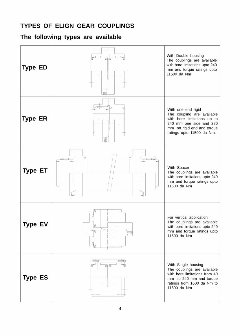
TYPES OF ELIGN GEAR COUPLINGS
The following types are available
With Double housingThe couplings are availablewith bore limitations upto 240mm and torque ratings upto11500 da Nm
With one end rigidThe coupling are availablewith bore limitations up to240 mm one side and 280mm on rigid end and torqueratings upto 11500 da Nm.
With SpacerThe couplings are availablewith bore limitations upto 240mm and torque ratings upto11500 da Nm
For vertical applicationThe couplings are availablewith bore limitations upto 240mm and torque ratings upto11500 da Nm
With Single housingThe couplings are availablewith bore limitations from 40mm to 240 mm and torqueratings from 1600 da Nm to11500 da Nm
Type ED
Type ER
Type ET
Type EV
Type ES
4
�� ����� �� ��� � � � �� � � � � ���
MISALIGNMENT������
���������
������
����������������
�
LENGTHDIAMETER TAPPING
��
�����
��������
� ! ���"#$%
� &
%$&' � �
�� ��� ��� ����� ��� �� � �� �� � � � �� �� � ����� ��� �� ���� ����
�� ��� �� ����� �� � �� �� �� ���� � � � � � ����� �� ���� ���� ����
�� �� ���� ��� ��� � �� � ��� ���� �� �� � �� �� �� ����� �� ���� ����� ��
�� ���� ���� ���� ��� �� � � ��� �� �� ��� �� �� � ����� ��� ��� ����� ���
�� ���� ���� ���� �� � � ��� �� ��� �� �� �� �� �� ��� ����� ����� ��� ��� ����� ���
�� ���� �� ���� �� � ��� ��� ��� �� ��� � �� � ��� � ����� ����� ��� ��� ���� ��
�� ���� ��� ���� ��� �� � � ��� �� ��� ��� � � � ��� �� ����� ����� ��� ���� ��� ���
�� �� ���� ���� ��� � �� �� �� ��� �� �� � �� � ��� �� ������ ����� ��� ����� ����� ����
�� ���� ���� ���� ��� � �� �� ��� ��� �� �� � �� � � ��� ����� ����� ��� ���� ��� ����
�� ��� ����� ����� � � ��� �� ��� ��� �� ��� � �� �� ��� �� ����� ����� �� ����� ����� ��
�� ���� ����� ����� �� ��� �� ��� ��� ��� �� � � � ��� ��� ����� ����� �� ��� ���� ����
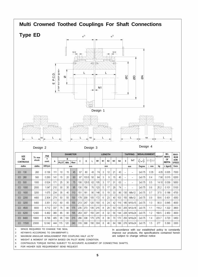
Design 2 Design 3 Design 4
1 SPACE REQUIRED TO CHANGE THE SEAL
2 KEYWAYS ACCORDING TO DIN:6885PART-1
3 MAXIMUM ANGULAR MISALIGNMENT PER COUPLING HALF ±0.75°
4 WEIGHT & MOMENT OF INERTIA BASED ON PILOT BORE CONDITION.
5 CONTINUOUS TORQUE RATING SUBJECT TO ACCURATE ALIGNMENT OF CONNECTING SHAFTS.
6 FOR HIGHER SIZE REQUIREMENT SEND REQUEST.
In accordance with our established policy to constantlyimprove our products, the specifications contained hereinare subject to change without notice
�� �� �� �()*(( �� �� ) +! , )��- �.� & �.*/�0��0��
5
Design 1
Multi Crowned Toothed Couplings For Shaft Connections
Type ED
LLL L LLN2 N3 N4
ØA
ØDØC
Ø
E P
.C.D
. L L
2-TA
P 'S
'xT
DEE
P @
180∞
N1
M1)
N1/2
M1)
N1/2
ØD
1
ØD
M
ØA ØB1
L1
ØB
E P
.C.D
.
ØC
L
E1 P
.C.D
.2-
TAP
'S'x
T D
EEP
@18
0∞
2-TA
P 'S
'xT
DEE
P @
180∞
N1
N1/2
1)
�� ����� �� ��� � � � ��
LENGTHDIAMETER
��
�����
��������
� ! ���"#$%
� &
%$&'
�� ��� ��� ����� ��� �� � �� � �� �� �� � � � ��� �� ���� ����
�� ��� �� ����� �� � �� �� � �� � �� ���� ���� � � � ��� ��� ���� ����
�� �� ���� ��� ��� � �� � � �� � ��� ���� ��� �� � �� ��� ��� ����� ��
�� ���� ���� ���� ��� �� � � �� � ��� ��� �� �� �� � ��� � ��� ��� ����� ���
�� ���� ���� ���� �� � � ��� � � ��� �� ��� ��� �� �� �� � ��� � ����� ��� �� ����� ���
�� ���� �� ���� �� � ��� � � ��� ��� ��� �� ��� ��� �� � ��� ����� ��� �� ��� ��
�� ���� ��� ���� ��� �� � � �� � ��� ��� �� � ��� ��� ��� �� �� ��� ����� ��� �� ����� ���
�� �� ���� ���� ��� � �� �� � �� ��� �� ��� ��� �� ��� �� � �� �� ������ ��� ��� ����� ����
�� ���� ���� ���� ��� � �� �� � �� ��� ��� ��� �� �� �� �� � ��� �� ����� ��� �� ���� ����
�� ��� ����� ����� � � ��� �� � ��� �� ��� ��� ��� �� �� ��� � �� ��� ����� ��� ���� ����� ��
�� ���� ����� ����� �� ��� �� �� ��� ��� ��� ��� ��� ��� ��� �� �� ��� ��� ����� ��� ��� �� ����
����� ��
��
��� ��
TAPPING������
���������
������
����������������
� ������
0�� 0�� �.*/� �� �� ��
��
�()*(( ) +! , )��- �.� &
�
�
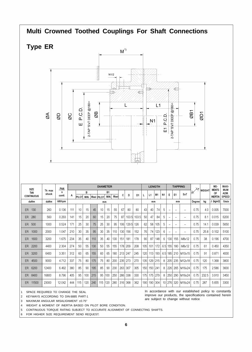
Multi Crowned Toothed Couplings For Shaft Connections
Type ER
1 SPACE REQUIRED TO CHANGE THE SEAL
2 KEYWAYS ACCORDING TO DIN:6885 PART-1
3 MAXIMUM ANGULAR MISALIGNMENT ±0.75°
4 WEIGHT & MOMENT OF INERTIA BASED ON PILOT BORE CONDITION.
5 CONTINUOUS TORQUE RATING SUBJECT TO ACCURATE ALIGNMENT OF CONNECTING SHAFTS.
6 FOR HIGHER SIZE REQUIREMENT SEND REQUEST.
In accordance with our established policy to constantlyimprove our products, the specifications contained hereinare subject to change without notice
6
�� � � �� � �
MISALIGNMENT ���� ��
���� ��
LENGTHDIAMETER TAPPING���� ��
�� �����
�� ��������
����
������
�� ��� ��� ����� ��� �� � �� �� � � �� �� ��� ��� �� ����
�� ��� �� ����� �� � �� �� �� ���� � � �� �� ��� �� ���� ����
�� �� ���� ��� ��� � �� � ��� ���� �� �� �� ��� ��� �� ���� �����
�� ���� ���� ���� ��� �� � � ��� �� �� ��� �� ��� ��� �� ��� �����
�� ���� ���� ���� �� � � ��� �� ��� �� �� �� ���� ��� ����� ��� �� ��� �����
�� ���� �� ���� �� � ��� ��� ��� �� ��� � �� � ����� ��� � ��� ����
�� ���� ��� ���� ��� �� � � ��� �� ��� ��� �� �� �� ����� ��� � ���� ���
�� �� ���� ���� ��� � �� �� �� ��� �� ��� �� ��� �� ������ ��� � ����� �����
�� ���� ���� ���� ��� � �� �� ��� ��� �� �� �� ��� ��� ����� ��� ���� ���
�� ��� ����� ����� � � ��� �� ��� ��� �� ��� � ��� �� ����� ��� ����� �����
��� ���� ����� ����� �� ��� �� ��� ��� ��� �� � ��� ��� ����� ��� ��� ����
��!" ��#�����$������$$ �� ��
LIM
ITE
D B
Y T
HE
CR
ITIC
AL
SP
EE
D A
ND
WE
IGH
T O
F T
HE
IN
TE
RM
ED
IAT
EH
OLL
OW
SH
AF
T
Multi Crowned Toothed Couplings For Shaft Connections
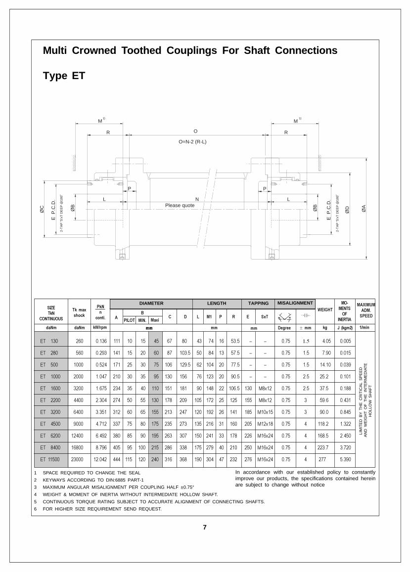
Type ET
� �
1 SPACE REQUIRED TO CHANGE THE SEAL
2 KEYWAYS ACCORDING TO DIN:6885 PART-1
3 MAXIMUM ANGULAR MISALIGNMENT PER COUPLING HALF ±0.75°
4 WEIGHT & MOMENT OF INERTIA WITHOUT INTERMEDIATE HOLLOW SHAFT.
5 CONTINUOUS TORQUE RATING SUBJECT TO ACCURATE ALIGNMENT OF CONNECTING SHAFTS.
6 FOR HIGHER SIZE REQUIREMENT SEND REQUEST.
In accordance with our established policy to constantlyimprove our products, the specifications contained hereinare subject to change without notice
��� ���� ����
��%��� %��� � &'(� �� �� �� $)*')) ���� �* +� ,�*�-. �&���
�� �
7
ØD
�
������������������������������������������������������������������������
M�
ØC
�
M�
ØA�
����������������������������������������������������������������������������������������������������������������������������������������
���������������������������������������������������������������������������������������������������������������������������������������������������������
������������������������������
�������������������������
E P
.C.D
. �
ØB
�L �
ØB
� L �
E P
.C.D
. �
P�
���������������������������������������������������������������������������������������������
O �
������������������������������������������������������������������������������������������������
������������������������������������������������������������������������������������������������
������������������������������������������������������������������������
R� R�
Please quote�
�
2-TA
P 'S
'xT
DEE
P @
180˚
�
�
P�
N�
2-TA
P 'S
'xT
DEE
P @
180˚
�
�
O=N-2 (R-L)�
�
1)�
�
1)�
�
�� ����� �� ��� � � � �� � � ���
MISALIGNMENT
�
LENGTHDIAMETER TAPPING
��
�����
��������
� ! ���"#$%
� &
%$&'
0�� 0�� �.*/� �� �� ��
�� ��� ��� ����� ��� �� � �� �� � � � �� � ����� ��� �� ����� ���
�� ��� �� ����� �� � �� �� �� ���� � � �� � ����� �� �� ����� ��
�� �� ���� ��� ��� � �� � ��� ���� �� �� ��� �� � ����� �� ��� ���� ���
�� ���� ���� ���� ��� �� � � ��� �� �� ��� �� �� �� ����� ��� ���� ����� ����
�� ���� ���� ���� �� � � ��� �� ��� �� �� �� �� �� ��� ����� ����� ��� ���� ����� ���
�� ���� �� ���� �� � ��� ��� ��� �� ��� � � �� � ����� ����� ��� ���� ���� ����
�� ���� ��� ���� ��� �� � � ��� �� ��� ��� � � �� �� ����� ����� ��� ���� ���� ����
�� �� ���� ���� ��� � �� �� �� ��� �� �� �� �� �� ������ ����� ��� ����� �� ����
�� ���� ���� ���� ��� � �� �� ��� ��� �� �� �� �� ��� ����� ����� ��� ���� ����� ��
�� ��� ����� ����� � � ��� �� ��� ��� �� ��� �� �� �� ����� ����� ��� ����� ���� ��
�� ���� ����� ����� �� ��� �� ��� ��� ��� �� � �� ��� ����� ����� ��� ���� ���� ����
������,������-
���������
������
����������������
�()*(( ���� ) +! , )��- �.� &
Multi Crowned Toothed Couplings For Shaft Connections
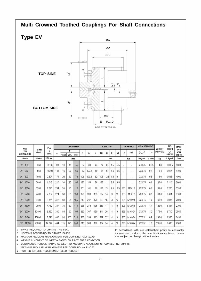
Type EV
1 SPACE REQUIRED TO CHANGE THE SEAL
2 KEYWAYS ACCORDING TO DIN:6885 PART-1
3 MAXIMUM ANGULAR MISALIGNMENT PER COUPLING HALF ±0.75°
4 WEIGHT & MOMENT OF INERTIA BASED ON PILOT BORE CONDITION.
5 CONTINUOUS TORQUE RATING SUBJECT TO ACCURATE ALIGNMENT OF CONNECTING SHAFTS.
* MAXIMUM ANGULAR MISALIGNMENT PER COUPLING HALF ±0.5°
6 FOR HIGHER SIZE REQUIREMENT SEND REQUEST.
� �
In accordance with our established policy to constantlyimprove our products, the specifications contained hereinare subject to change without notice
8
TOP SIDE
BOTTOM SIDE
ØA
L
M
ØB
L
M
E P.C.D.
N1 N
ØD
ØC
1)
N1
2-TAP 'S'xT DEEP @180∞
1)
N2
�� �����
�
DIAMETER
��
�����
��������
� ! ���"#$%
� &
%$&'
0�� 0�� �.*/� ��
�� ���� ���� ���� ��� � � ��� �� �� ��� ��� ����� ����� ��� ���� ���� ���
�� ���� �� ���� ��� � ��� ��� �� �� � � ����� ����� ��� �� ����� ��
�� ���� ��� ���� � �� � � ��� ��� ��� � �� ����� ����� ��� ��� ����� ���
�� �� ���� ���� ��� � �� �� �� �� �� � �� ������ ����� ��� ��� ��� ����
�� ���� ���� ���� ��� � �� �� ��� �� �� � ��� ����� ����� ��� � ����� ����
�� ��� ����� ����� �� � ��� �� ��� �� �� � �� ����� ����� �� ��� ���� ��
�� ���� ����� ����� ��� �� ��� �� ��� ��� � � ��� ����� ����� �� �� ��� ����
�.� &
�� ��� � �� �
LENGTH
���
TAPPING������
MISALIGNMENT ��������
������
���������������
�� �� �()*(( ���� ) +! , )��-
� �
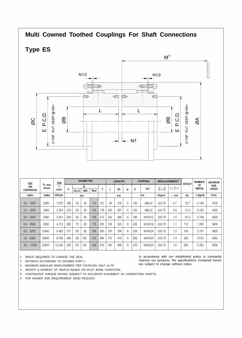
1 SPACE REQUIRED TO CHANGE THE SEAL
2 KEYWAYS ACCORDING TO DIN:6885 PART-1
3 MAXIMUM ANGULAR MISALIGNMENT PER COUPLING HALF ±0.75°
4 WEIGHT & MOMENT OF INERTIA BASED ON PILOT BORE CONDITION.
5 CONTINUOUS TORQUE RATING SUBJECT TO ACCURATE ALIGNMENT OF CONNECTING SHAFTS.
6 FOR HIGHER SIZE REQUIREMENT SEND REQUEST.
In accordance with our established policy to constantlyimprove our products, the specifications contained hereinare subject to change without notice
M
ØC ØAØB
L
E P
.C.D
.
ØB
E P
.C.D
. L
N1/2 N1/2
2-TA
P 'S
'xT
DEE
P @
180∞
2-TA
P 'S
'xT
DEE
P @
180∞
N1
1)
Multi Cowned Toothed Couplings For Shaft Connections
Type ES

����������
���������
��������� ���� �� ����������
��������� ���� ��� �
�������� ������������� ����� �!� ��
������
���!��� ��""�"�"����"�"��"��
"�"� ���"����"��"�� �
����� ��""�"����
��#����� ������$������ ����� �!� ��
��
���!��� ��"������ �
���� ��"������ �
������� ������%&!����� ����� �!� ��
������� ���������
���!��� ��" "��� ������"�
�����"�
����� ��" "�� ���
��#����� �����'���� ������ ����� �!� ��
���������
��������
���!��� ������� � ���� ��� �
�� ������� �"
����� ������� ��
������ � ������ ������ ����� �!� ��
������
���!��� �����"�����"�"�����"�"
����� �����"�"���
��#����� ��������!���� ����� �!� ��
������
���!��� ���" ��� "������"�"�
����� ���" ���"�"�
��#����� ��������!���� ����� �!� ��
���������
���!��� �� ����"����������"
����� �� ����"���
��#����� ������(�)���� ����� �!� ��
�������
���!��� �����"��������"�""��"�""
����� �����"�"���
��#����� ������$�%���� ����� �!� ��
����������
����
���!��� ���"���������� �
����� ���"������
��#����� ������!*%���� ����� �!� ��
��� �������
�����
���!��� ��������"����������
��� ������""���
����� �������� ��
�������� ������ ������ ����� �!� ��
��������
���!��� �����"" �"��""������""����"
����� �����""����
��#����� ������$�)���� ����� �!� ��
�����������
���!����������������������"������� ��
�����������������
��#�������������� ���� ����� �!� ��
�����������
�� �����
���!��� ���������
����������� ����� ��
����� ��������
��#����� ������������� ����� �!� ��
�������������
������������������� ������������������������ ��������������������������� ������� ������������������������� � ���� � ������ �����������������!!�
���������"����#$���%����������&'�"�"�"(���(�')*+��#$���%����$���&�"���"�"(���(�'
������������� ���������������
������������������� ��������,�� �,��-���� �.�����/���"�0"��" 1���������� �2"3�4"�������������
5���"�%�����,��,��� ��,��,�,� ��,��,��� ��,��,��, ���������� ����,������������$��"$&�"�"'(�"�"(���(�'�
��������������
����������� �����������������$������� �6��������"��������5��7�
����8��"���� ��������������!��� ���!� ��!��� ��,�! ��������!��� ���,�
�������"�"(��9$��&"�"(��$���8��"�"�"(���(�'
������������
�������������������� ��������:������������� ������ ���,�� �����!
������:����������!����������$��"$9"'(&"'(�"�"(���(�'
�����������
��������� ��������������� �4��3"����#"��"
;�-�$�2�.����� ���$������������:������!����!��������:������!����!��
�����������&��$�"�"(���(�'