elementy prowadzace 1 - Albeco · AFNOR* DAA A;A:.FH. Demountable Pillars, conical, with Ball Cage...
101
Guide Elements subject to alterations D2
Transcript of elementy prowadzace 1 - Albeco · AFNOR* DAA A;A:.FH. Demountable Pillars, conical, with Ball Cage...

Guide Elements
subject to alterationsD2

The great importance of exact alignment between punches and matrices in stamping dies has been recognized widely. The accuracy and maintenance of this alignment depends entirely on the quality and wear resistance of the guide elements.
As a consequence of recent rapid develop-ments in stamping techniques it has also been accepted that conventional bush-pillar sets of casehardened steel can no longer stand up to the demands of the modern press shop with its more sophisticated dies, ever faster presses and the stresses in today’s carbide tools.
The introduction of FIBRO Guide Elements made available an extensive range, principal-ly based on superlative quality, and compri-sing some new, highly advanced bearing ma-terials as well as novel assembly techniques of superior accuracy.
Recent additions have further broadened this range, especially in regard of demountable guiding components.
All FIBRO Guide Bushes for permanent fixing are laid out for epoxy-bonding. This highly reliable method ensures unparalleled accu-racy together with the elimination of shrink allowances and rectification honing.
Ball Bearing Guides principally excel in un-demanding maintenance and through the complete absence of bearing play. Their easy movement on the bench makes them very popular with die makers. Highest stroking speeds present no problems. But common to all ball bearings there remains the characte-ristic weakness to shock loads, the danger of ball impingement. To some extent this can be compensated for by oversized pillar diame-ters and the use of four-pillar die sets.
The group of Sliding-Type Guides aJords much greater stability, partly due to the dam-ping eJect of the all-important, vital oil film . . . which in the past used to be threatened always by the vagaries of lubrication service and the propensity to rupture at high fre-quencies of travel reversal.
Extensive protection against these perils is oJered by FIBRO Sintered Ferrite Bushes. Used in most of our sliding guide systems, their advanced technology comprises:
– porous structure, vacuum-filled with oil – carbonitrided surface of extreme hardness – outstanding friction properties – exceptional wear-resistance – thousands of oil-retaining porosity pockets.
In combination with our mirror-finished pil-lars, ferrite guide bushes represent a guiding system of alltogether superior properties. A system that virtually precludes seizing under all but the most extreme running conditions.
Beyond such limitations there exist combina-tions of high velocities with very short strokes where even ferrite bushes cannot guarantee permanence of the oil film. Here, the rigidity of the sliding guide has to be weighed up against the safety of ball bea-rings: die set guides are not entirely without problems yet! But at FIBRO we find ourselves very busy indeed with the remainder.
Technical progress may incur modifications without notice.
FIBRO GUIDE ELEMENTS – DESIGNED AND PRODUCED BY PEOPLE IN PURSUIT OF PERFECTION.
Guide Elements
D3subject to alterations

Contents
Page Notes on Guide Elements D9
Sliding Guide Systems: Clearance and Pairing Recommendations
D10- D11
Selection matrix Guide Pillars – Guide Bushes
D12
202.19. Guide Pillars, small dimensions D14
206.51. Ball Cages small dimensions D15
206.54.
Guide Bushes, small dimensiones
202.19. Guide Pillars DIN 9825/ISO 9182-2
D16
202.17. Guide Pillars with Ball Cage Retainer
202.22. 202.23. 202.24.
Guide Pillars ~DIN 9825/ ~ISO 9182 press-in type, with internal threads
D17
202.21.
Guide Pillars – endwise bolt-on type ~DIN 9825/~ISO 9182-2
D18
202.55.
Guide Pillars – endwise bolt on type with Ball Cage Retainer
D18
202.29.
Guide Pillars ECO-LINE ~DIN 9825/~ISO 9182-2
D19
202.31.
Guide Pillars ECO-LINE endwise bolt on type ~DIN 9825/~ISO 9182-2
D20
2021.50.
Demountable Pillars, conical, DIN 9825/ISO 9182-4 similar AFNOR*
D22
2021.58.
Demountable Pillars, conical, with Ball Cage Retainer
202.53.
Retaining disc with head cap screw, similar AFNOR
D23
2021.53.
Retaining disc with countersunk head screw, DIN 9825/ISO 9182-4
Page2021.39.
Liner Bushes, DIN 9825/ISO 9182-4, for conical pillars 2021.50.
D24
210.39.
Liner Bushes AFNOR, for conical pillars 2021.50.
D25
2022.25.
Guide Pillars ~AFNOR with Retaining Ring Groove
D26
2022.12.
Guide Pillars to Daimler with Pilot Taper, for Large Tools and Snap Ring Groove
D27
2022.15.
Guide Pillars to VDI 3356, with Pilot Taper, for Large Tools
D28
2022.17.
Guide Pillars to VW, with Groove, for Large Tools
D29
2022.16.
Guide Pillars to Daimler, for Large Tools with Snap Ring Groove
D30
2022.19.
Guide Pillars for Large Tools D31
2022.13.
Guide Pillars to VW, with 5° Pilot Taper
D32
2022.16.45.
Guide Pillars to CNOMO, with Groove
D33
2022.29.
Guide Pillars to WDX with Collar, with Screw Clamps
D34
2021.46.
Demountable Pillars DIN 9825/ ~ISO 9182-5 with Collar and Screw Clamp Retention
D35
2021.44.
Demountable Pillars, with Ball Cage Retainers
2021.43.
Retaining Disc with Screw
2025.94.
Ball guide units, complete to Daimler standard
D36
D4 Änderungen vorbehalten

Contents
Page2021.29.
Guide Pillars with collar, ECO-LINE
D37
206.41. 2062.44.
202.61. 2061.44.
Ball Guides for highest stroking speeds
D38
2020.63. 2020.62.
202.60.
Stripper-Mounted Pillars D39-D41
2021.64.
Stripper-Mounted Retaining Bushes, conical pillar fit
D42
2020.64.
Stripper-Mounted Guide Pillars, conical pillar fit
D43
2024.94. 2024.96.
Guide units Million-Guide D44-D47
2031.70.
Rectangular Mounting Flanges Bronze with Non-Liquid Lubricant
D48
2031.01. 2031.31. 2031.41.
Rectangular Mounting Flanges for Guide Pillars and Guide Bushes – without screw holes –
D49
2031.02. 2031.34. 2031.42.
Rectangular Mounting Flanges for Guide Pillars and Guide Bushes – with screw holes –
D50
2031.04. 2031.38. 2031.44.
Shallow Mounting Flanges, Rectangular, for Guide Pillars and Guide Bushes, – with screw holes –
D51
2032.02. 2032.70.
Rectangular Mounting Flanges for Guide Pillars and Guide Bushes Bronze with Non-Liquid Lubricant
D52
Page2051.32.
Sintered Ferrite Guide Bushes carbonitrided, for slip fit bonding DIN 9831/ISO 9448-2
D54
Special Ball Bearing Cages – Brass
D55
Tables: Safe Loads for FIBRO Ball Bearing Guides
D56-D57
2061.44.
Guide Bushes for Ball Bearings, for slip fit bonding, DIN 9831/ISO 9448-3
D58
206.49.
Guide Bushes for Ball Bearings, for slip fit bonding, similar AFNOR
D59
206.71. Ball Cages with securing ring groove
D60
206.72. Circlips
206.73. Ball Cages with cage spacing D61206.75.
Ball Cages with Circlip DIN 472 and Fastning Ring Groove
D62
2061.47.
Guide Bushes for Ball Bearings with stroke Limitation for slip fit bonding
D63
2081.67.
Headed Guide Bushes for Ball Bearings, with ball cage retainer
D64
2091.67.
Flanged Guide Bushes for Ball Bearings, with ball cage retainer
D65
2061.82. Roller Cages with circlip groove D66
2061.84. Roller Cages with mounting aid
2081.81. 2081.84. 2081.85.
Headed Guide Bushes, to ISO 9448, Steel, with bronze-coated internal bore
D67-D69
2081.31. 2081.32. 2081.33. 2081.34. 2081.35.
Headed Guide Bushes, sintered ferrite, carbonitrided, long-term lubrication, DIN 9831/ISO 9448-6
D70-D74
Änderungen vorbehalten D5

Page2081.91. 2081.94. 2081.95.
Headed Guide Bushes, bronze plated, ECO-LINE
D75-D77
2081.71. 2081.74. 2081.75.
Headed Guide Bushes, bronze with solid lubricant rings, ECO-LINE
D78-D80
2081.44. 2081.45. 2081.46. 2081.47. 2081.49.
Headed Guide Bushes for Ball Bearings , DIN 9831/ISO 9448-7
D81-D85
2091.31. 2091.32. 2091.34.
Flanged Guide Bushes, sintered ferrite, carbonitrided, DIN 9831/ISO 9448-4
D86-D88
2091.71. 2091.72. 2091.74.
Flanged Guide Bushes DIN 9831/ISO 9448-5 Bronze with solid lubrication rings, ECO-LINE
D89-D91
2091.44. 2091.45. 2091.46.
Flanged Guide Bushes DIN 9831/ISO 9448-5 for Ball Bearings
D92-D94
210.31. 210.34. 210.35.
Headed Guide Bushes, carbonitrided, long-term lubrication, similar AFNOR
D95-D97
210.44. 210.46.
Headed Guide Bushes for Ball Bearings similar AFNOR
D98-D99
210.45.
Guide Bushes with Collar for Ball Bearings similar AFNOR, Slotted Nuts
D100
210.85.
Guide Bushes with Collar, Bronze coated to AFNOR, Slotted Nuts
D101
PageOilless Guide Elements D103-
D2282053.70. Thrust Washers D105
2052.70. Guide Bushes D106- D117
2085.70. Guide Bushes with collar
2085.71. Guide Bushes with collar
2086.70. Guide Bushes with collar
2085.72. Guide Bushes with collar
2082.70.55. Guide Bushes with collar to VW
2082.70. Guide Bushes to DIN 9834/ISO 9448
2072.45. Screw clamps to DIN 9832
2082.71. Guide Bushes to NAAMS
2072.46 Screw Clamps
2086.71. Guide Bushes with collar to NAAMS
2072.47 Screws Clamps to NAAMS
2102.70. Guide Bushes CNOMO
2102.71. Guide Bushes CNOMO
2073.45. Securing Flanges
2072.48.45. Screw Clamps to CNOMO
2961.71. 2961.73. 2961.70.
Flat Guide Bars Cut-to-lenght with and without CSK-Holes
D119- D121
2961.74. Retaining Plates to VDI 3357 Bronze with Non-Liquid Lubricant
D122- D124
2961.79. Retaining Plates, Steel, VDI 3357
2961.81. Retaining Plates, Steel with Non-Liquid Lubricant, VDI 3357
2961.82. Retaining Plates, Steel with Non-Liquid Lubricant
2961.79.45. Retaining Plates, Steel, to CNOMO
2961.81.45. Retaining Plates, Bronze with Non-Liquid Lubricant, to CNOMO
2961.78. Retaining Plates, Bronze with Non-Liquid Lubricant
2961.75. 2961.76. 2961.77.
Flat Guide Bars D129- D131
Contents
D6 Änderungen vorbehalten
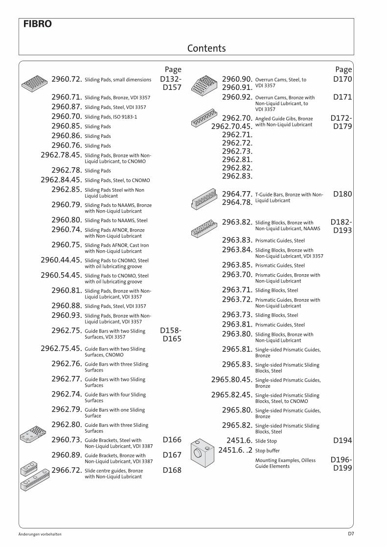
Page2960.72. Sliding Pads, small dimensions D132-
D1572960.71. Sliding Pads, Bronze, VDI 3357
2960.87. Sliding Pads, Steel, VDI 3357
2960.70. Sliding Pads, ISO 9183-1
2960.85. Sliding Pads
2960.86. Sliding Pads
2960.76. Sliding Pads
2962.78.45. Sliding Pads, Bronze with Non-Liquid Lubricant, to CNOMO
2962.78. Sliding Pads
2962.84.45. Sliding Pads, Steel, to CNOMO
2962.85. Sliding Pads Steel with Non Liquid Lubicant
2960.79. Sliding Pads to NAAMS, Bronze with Non-Liquid Lubricant
2960.80. Sliding Pads to NAAMS, Steel
2960.74. Sliding Pads AFNOR, Bronze with Non-Liquid Lubricant
2960.75. Sliding Pads AFNOR, Cast Iron with Non-Liquid Lubricant
2960.44.45. Sliding Pads to CNOMO, Steel with oil lubricating groove
2960.54.45. Sliding Pads to CNOMO, Steel with oil lubricating groove
2960.81. Sliding Pads, Bronze with Non-Liquid Lubricant, VDI 3357
2960.88. Sliding Pads, Steel, VDI 3357
2960.93. Sliding Pads, Bronze with Non-Liquid Lubricant, VDI 3357
2962.75. Guide Bars with two Sliding Surfaces, VDI 3357
D158- D165
2962.75.45. Guide Bars with two Sliding Surfaces, CNOMO
2962.76. Guide Bars with three Sliding Surfaces
2962.77. Guide Bars with two Sliding Surfaces
2962.74. Guide Bars with four Sliding Surfaces
2962.79. Guide Bars with one Sliding Surface
2962.80. Guide Bars with three Sliding Surfaces
2960.73. Guide Brackets, Steel with Non-Liquid Lubricant, VDI 3387
D166
2960.89. Guide Brackets, Bronze with Non-Liquid Lubricant, VDI 3387
D167
2966.72. Slide centre guides, Bronze with Non-Liquid Lubricant
D168
Page2960.90. 2960.91.
Overrun Cams, Steel, to VDI 3357
D170
2960.92. Overrun Cams, Bronze with Non-Liquid Lubricant, to VDI 3357
D171
2962.70. 2962.70.45.
2962.71. 2962.72. 2962.73. 2962.81. 2962.82. 2962.83.
Angled Guide Gibs, Bronze with Non-Liquid Lubricant
D172- D179
2964.77. 2964.78.
T-Guide Bars, Bronze with Non-Liquid Lubricant
D180
2963.82. Sliding Blocks, Bronze with Non-Liquid Lubricant, NAAMS
D182- D193
2963.83. Prismatic Guides, Steel
2963.84. Sliding Blocks, Bronze with Non-Liquid Lubricant, VDI 3357
2963.85. Prismatic Guides, Steel
2963.70. Prismatic Guides, Bronze with Non-Liquid Lubricant
2963.71. Sliding Blocks, Steel
2963.72. Prismatic Guides, Bronze with Non-Liquid Lubricant
2963.73. Sliding Blocks, Steel
2963.81. Prismatic Guides, Steel
2963.80. Sliding Blocks, Bronze with Non-Liquid Lubricant
2965.81. Single-sided Prismatic Guides, Bronze
2965.83. Single-sided Prismatic Sliding Blocks, Steel
2965.80.45. Single-sided Prismatic Guides, Bronze
2965.82.45. Single-sided Prismatic Sliding Blocks, Steel, to CNOMO
2965.80. Single-sided Prismatic Guides, Bronze
2965.82. Single-sided Prismatic Sliding Blocks, Steel
2451.6. Slide Stop D1942451.6. .2 Stop buffer
Mounting Examples, Oilless Guide Elements
D196- D199
Contents
Änderungen vorbehalten D7

Page2441.11.0. Centering Units with Adjusting
WasherD200- D204
2441.11. Centering Units without Adjusting Washer
2441.11.3. Adjusting Washers
2441.13.45. Centering units to CNOMO
2441.13.3.45. Adjusting Washers
2441.13. Centering Units to CNOMO
2441.13.3. Adjusting Washers
2445.10. Centering pins to VW standard D2062445.11.
Centering pins to Daimler standard
D207
206.91. 206.92.
Concertina Shrouds D208- D209
206.93.
Spacer Bushes
206.94.
Spacer Tubes
241.18.
Helical Springs for Ball Cage Retention
D210
202.91. 202.92.1.
202.93.
Cage Retainers D211- D212
Page206.95.
2061.95. Pillar Wipers D214
244.00.2.
Lifter Pins for Press Tool Strips D215
207.45 2072.45. 2072.46 2072.47 2071.45
Screw Clamps D216- D217
2073.45. Securing Flanges D2182072.48.45. Screw Clamps, to CNOMO
2444.12 2444.13
Spacer Plates, toothed D219
2443.10. Guides D220-2443.12. Guides with Part Position
Control and SpringD222
2443.13. Guides with Part Position Control to VDI
Assembly Guidelines for Guide Elements, Tolerances for Fitment
D224- D228
Contents
D8 Änderungen vorbehalten

FIBRO Precision Sliding Guide, bronze-coatedconsists of a steel body with bronze-coated running surface with helical oil groove and a grease nipple for lubrication.
The steel body guarantees excellent resistance to breaking, even when subject to high loading at the edges.
FIBRO Sliding Bearings with Non-Liquid LubricantThe pockets containing the non-liquid lubricant occupy some 25 to 30 per cent of the bearing surface consisting of a bronze matrix.
After an initial oil lubrication on assembly, these elements are maintenance-free.
Wherever there is a demand for non-susceptibility against impact, contamination and heat, FIBRO Maintenance-Free Bearings find their ideal application.
We recommend to apply the tolerance classes H7/f6 to bush/pillar combinations using these elements.
FIBRO Precision Ball Bearing GuidesCareful manufacture at narrowest tolerances, and exactly the right amount of preloading* result in a play-free guide element of exceptional performance potential. Our superfinished running surfaces further enhance the advantages of ball bearing guides. Toolmakers favour ball bearing buides because of their free movement on the bench. FIBRO ball bearing guides have brass ball cages – a material giving optimum results in stability and ball density. Despite their unquestionable reliability at high speeds in particular, ball bearing guides with their point contact of the balls remain somewhat sensitive to shock and sustained radial loads. To some extent, generous dimensioning of pillar diameters helps to compensate for this inherent disadvantage. * Average preloading: 4 µm on pillars from 8 to 12 mm diameter 7– 9 µm on pillars from 15 to 16 mm diameter 9–11 µm on pillars from 18 to 42 mm diameter 11–13 µm on pillars from 50 to 80 mm diameter
Notes on: Guide Elements
FIBRO Precision Sliding Guides – Carbonitrided Sintered Ferrite Bushes
These guides employ bushes made from sintered ferrite of high purity with carbonitrided surface. Bearing surfaces are fine-ground.
The sintered ferrite has a porosity content of 18–20 % by volume, vacuum filled with special lubricant FIBROLIT LD. As additional long term lubrication it is recommended to fill up the grove in the bushing with FIBROLIT LD 280.34 – see page H 14. Even under arduous running conditions, this material can be relied upon for good protection against oil film rupture.
Under no circumstances must molybdenum disulfite be added to the lubricant. For bearing clearance ranges – see page D 11.
FIBRO Precision Roller GuidesIn comparison to ball bearing guides, FIBRO Roller Guide Elements have considerably higher capacities for radial loads. The much larger contact area of the rollers permits a significant reduction in preload values. This affords a longer service life of the units.
The following preload values apply to FIBRO Roller Guides:
For static loads/low velocities or dynamic loads/high velocities pillar diameters up to pillar diameters up ton Ø 25 = 2,5 µm Ø 25 = 1,5 µmØ 30/32 = 3 µm Ø 30/32 = 2 µmØ 40–50 = 3,5 µm Ø 40–50 = 2,5 µmØ 63 = 4 µm Ø 63 = 3 µm
Use only pairing class guide pillar red = .30guide bush yellow = .10
subject to alterations D9

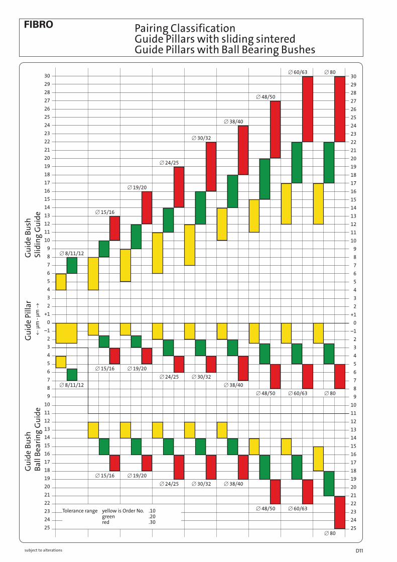
Pairing Classification Guide Pillars with sliding sintered Guide Pillars with Ball Bearing Bushes
Cutting Sliding guide Ball bearing
clearance bearing clearance preloading small small large Piece parts with small tolerances, closely specified cut edge Pairing 1 properties and contours – also parts from thin material medium medium medium Piece parts from sheet thicker than 1 mm – also preferably for Pairing 2 progression dies large large small Where demands on edges and burrs are not stringent; note that Pairing 3 large die clearances require smaller shearing forces
Selection of punch-matrix clearance is largely determind by piece part charcteristics such as percentage of sheared land versus breakaway,but also by demands on burr formation. Further criteria are: properties of piece part materials, conditions of the tool as well as the condition of the eccentric press.
Colour coding by paainted dots Sliding guide Ball bearing
Pillar Bush Pillar Bush Colour Order No Colour Order No Colour Order No Colour Order No Pairing 1 yellow yellow yellow red green yellow yellow green green red Pairing 2 green green yellow yellow red yellow green green yellow green red red Pairing 3 red red green yellow green red red green yellow red red yellow
Selection Criteria: die clearance – stock thickness – material
Note:Please note that tight bearing clearances are normally unsuitable for 4-pillar die sets. In general, wherever retainer bore geometry is not absolutely perfect, pairings 2 and 3 must be chosen. The pairing classification does not signify differences in quality, rather a selection of the necessary bearing clearance in the case of guide pillars or preloading in the case of ball bearings (see also chart on page D 11).
Ordering Code (example):Guide Pillar, tolerance range 1, yellow = 202.19.040.260.10 or green is then .20 Sliding guide, tolerance range 1, yellow = 2081.31.040.10
.10
.20.10.10
.20
.30
.10
.20
.10
.20
.10
.20
.30
.10
.20
.30
.10
.10
.20
.30
.20
.30
.30
.20
.10
.30
.30
.30
.20
.30
.30
.10
.20
.10
subject to alterationsD10
30
29
28
27
26
25
24
23
22
21
20
19
18
17
16
15
14
13
12
11
10
9
8
7
6
5
4
3
2
+1
0
–1
2
3
4
5
6
7
8
9
10
11
12
13
14
15
16
17
18
19
20
21
22
23
24
25
30
29
28
27
26
25
24
23
22
21
20
19
18
17
16
15
14
13
12
11
10
9
8
7
6
5
4
3
2
+1
0
–1
2
3
4
5
6
7
8
9
10
11
12
13
14
15
16
17
18
19
20
21
22
23
24
25
[ 48/50
[ 60/63 [ 80
[ 80
[ 60/63[ 48/50
[ 38/40[ 30/32[ 24/25
[ 19/20[ 15/16
[ 8/11/12
[ 15/16 [ 19/20
[ 24/25 [ 30/32
[ 38/40
[ 48/50 [ 60/63 [ 80
[ 8/11/12
[ 15/16
[ 19/20
[ 24/25
[ 30/32
[ 38/40
Pairing Classification Guide Pillars with sliding sintered Guide Pillars with Ball Bearing Bushes
Gu
ide
Bu
sh
Ba
ll B
ea
rin
g G
uid
eG
uid
e B
ush
Sl
idin
g G
uid
eG
uid
e Pi
llar
← µ
m -
µm
→
Tolerance range yellow is Order No. .10 green .20 red .30
subject to alterations D11
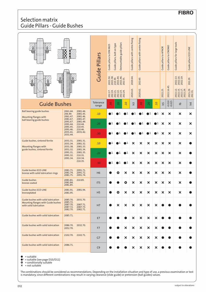
Selection matrix Guide Pillars - Guide Bushes
Gu
ide
pil
lars
EC
O-L
INE
20
21
.29
. 2
02
.29
.2
02
.31
.h
4
ÑÑ
Ñl
ll
ll
ll
ll
ll
Gu
ide
pil
lars
fo
r la
rge
too
ls2
02
2.1
2.
20
22
.13
. 2
02
2.1
5.
20
22
.16
. 2
02
2.1
7.
20
22
.19
. 2
02
2.2
9.
f6
ÑÑ
ÑÑ
ÑÑ
ÑÑ
Ñl
ll
ll
Gu
ide
pil
lars
to
CN
OM
O2
02
2.1
6.4
5.
-0.0
10
-0.0
25
ÑÑ
ÑÑ
ÑÑ
ÑÑ
Ñl
ll
ll
Gu
ide
pil
lars
to
AFN
OR
20
22
.25
.h
5
ÑÑ
ÑÑ
ÑÑ
ÑÑ
Ñl
ll
ll
Gu
ide
pil
lars
wit
h c
entr
e fi
xin
g2
02
0.6
2.
20
2.6
0.
.10
l1
l1
l1
ÑÑ
ÑÑ
ÑÑ
ÑÑ
ÑÑ
Ñ
.20
l1
l1
l1
ÑÑ
ÑÑ
ÑÑ
ÑÑ
ÑÑ
Ñ
.30
l1
l1
l1
ÑÑ
ÑÑ
ÑÑ
ÑÑ
ÑÑ
Ñ
Gu
ide
pil
lars
wit
h c
entr
e fi
xin
g2
02
0.6
3.
20
20
.64
.h
3
l1
l1
l1
ÑÑ
ÑÑ
ÑÑ
ÑÑ
ÑÑ
Ñ
Gu
ide
pil
lars
to
DIN
98
25
G
uid
e p
illa
rs, b
olt
-on
typ
e D
emo
un
tab
le g
uid
e p
illa
rs
20
2.1
7.
20
21
.50
.2
02
.19
. 2
02
1.5
8.
20
2.2
1.
21
0.3
9.
20
2.2
2.
20
21
.44
.2
02
.23
. 2
02
1.4
6.
20
2.2
4.
20
2.5
5.
.10
l1
l1
l1
l1
l1
l1
Ñ£
ÑÑ
lÑ
Ñl
.20
l1
l1
l1
l1
l1
l1
£l
£Ñ
ll
ll
.30
l1
l1
l1
l1
l1
l1
ll
ll
ll
ll
Gu
ide
Pil
lars
Tolerance range
.10
.20
.30
.10
.20
.30
H6
IT5
H5
H7
E7
F7
G7
C9
Guide Bushes2061.44. 2081.44. 206.49. 2081.45. 2061.47. 2081.46. 2081.67. 2081.47. 2091.67. 2081.49. 2091.44. 210.44. 2091.45. 210.45. 2091.46. 210.46. 2031.41. 2031.42. 2031.44.
2031.31. 2081.31. 2031.34. 2081.32. 2031.38. 2081.33. 2051.32. 2081.34. 2091.31. 2081.35. 2091.32. 210.31. 2091.34. 210.34. 210.35.
2081.71. 2091.71. 2081.74. 2091.72. 2081.75. 2091.74.
2081.81. 210.85. 2081.84. 2081.85.
2081.91. 2081.94. 2081.95.
2085.70. 2031.70. 2085.72. 2087.70. 2087.71. 2087.72. 2087.73. 2082.70. 2082.71.
2085.71.
2086.70. 2032.70. 2052.70.
2102.70. 2102.71.
2086.71.
Ball bearing guide bushes Mounting flanges with ball bearing guide bushes
Guide bushes, sintered ferrite Mounting flanges with guide bushes, sintered ferrite
Guide bushes ECO-LINE bronze with solid lubrication rings
Guide bushes bronze coated
Guide bushes ECO-LINE bronzeplated
Guide bushes with solid lubrication Mounting flanges with Guide bushes with solid lubrication
Guide bushes with solid lubrication
Guide bushes with solid lubrication
Guide bushes with solid lubrication
Guide bushes with solid lubrication
● = suitable ●1 = suitable (see page D10/D11) £ = conditionally suitable Ñ = not suitable
The combinations should be considered as recommendations. Depending on the installation situation and type of use, a previous examination or test is mandatory, since different combinations may result in varying clearance (slide guide) or pretension (ball guides) values.
subject to alterationsD12

subject to alterations D13

Guide Pillars, small dimensions 202.19.
Material: alloy tool steel
Hardness: hardened to 60 + 4 HRC
Remarks: or from stainless steel on request
Hardness: hardened to 56 + 2 HRC
Execution: fine-ground and superfinished
Ordering Code (example):Guide Pillar = 202.19.d1 = 4 mm = 004.l1 = 80 mm = 080Order No = 202.19.004.080
202.19.d1 3 4 5 6 8l1 30 ● 40 ● ● ● 50 ● ● ● ● ● 60 ● ● ● ● ● 80 ● ● ● ● ●100 ● ● ● ●125 ● ●140 ● ●160 ● ●
202.19.
subject to alterationsD14

206.51.d1 3 4 5 6 8k 1 1 1 1 1l1 total number of balls10 21 21 29 3615 35 35 49 61 6120 49 49 69 69 6925 64 89 89 8930 109 109 10940 149
206.51. Ball Cages, small dimensions 206.54 Guide Bushes, small dimensions
Material: Roller bearing steel 100 Cr 6
Hardness: hardened to 60 + 4 HRCRemarks: available in stainless steel
on request
Execution: Guide Bush bores d2 fine-honed to IT3
Ordering Code (example):Guide Bush = 206.54.d1 = 3 mm = 003.l1 = 20 mm = 020Order No = 206.54.003.020
206.54.
206.51.
Ordering Code (example):Ball cage = 206.51.d1 = 3 mm = 003.l1 = 15 mm = 015Order No = 206.51.003.015
206.54.d1 3 4 5 6 8d2 5 6 7 8 10d3 7 8 10 11 14l1 10 ● ● ● 15 ● ● ● ● ●20 ● ● ● ● ●25 ● ● ● ●30 ● ● ●35 ● ●40 ●
Material:
Cage: Brass
Balls: hardened steel (DIN 5401)
subject to alterations D15

202.19.d1 10 11 12 15 16 19 20 24 25 30 32 38 40 48 50 60 63 80l2 3 3 3 4 4 4 4 6 6 6 6 6 6 8 8 8 8 8l1 80 90 100 112 125 140 160 180 200 224 250 280 315 355 400 450 500 550 600 700 800
d1<
10
see
pag
e D
12
Guide Pillars 202.17. DIN 9825/ISO 9182-2 202.19.
202.17.Guide Pillars (∅ 38–63) with Ball Cage Retainer
Dimensions of ball cage retainer: see page D211.
Mounting Examples
202.19. 202.17. with Ball Cage Retainer
Material: Steel, surface hardened
Core strength: ^ 900 N/mm2
Surface Hardness: 60 + 3 HRC (induction hardened)
Hardness Penetration: ^ 1,8 mm (diameter up to 12 mm: troughhardened)
Execution: precision ground, superfinished
Remarks: method of manufacturing entails that centre holes are not concentric with O.D.
Diameter 10–12 only available
in Tolerance range yellow = .10
Note:Colour Code Combinations/Clearances – see pages D 10 and D 11.
Ordering Code (example):Guide Pillar = 202.19.d1 = 40 mm = 040.l1 = 200 mm = 200.Tolerance range – yellow = 10Order No = 202.19.040.200.10
Ordering Code (example):Guide Pillar with Cage retainer = 202.17.d1 = 40 mm = 040.l1 = 200 mm = 200.Cage holder size 3 = 3.Tolerance range – yellow = 10Order No = 202.17.040.200.3.10
Tolerance range yellow = .10 green = .20 red = .30
subject to alterationsD16

Guide Pillars 202.22. 202.23. ~DIN 9825/~ISO 9182-2 202.24. with internal threads
202.22.
202.23.
202.24.
202.22./202.23./202.24.
Ordering Code (example):Pillar, threaded holes/both ends = 202.22.d1 = 30 mm = 202.22.030.l1 = 200 mm = 202.22.030.200.Tolerance range – green = 202.22.030.200.20Order No = 202.22.030.200.20
Material: Steel, surface hardened
Core strength: ^ 900 N/mm2
Surface Hardness: 60 + 3 HRC (induction hardened)
Hardness Penetration: ^ 1,8 mm
Execution: precision ground, superfinished
Note: Dimensions of pillar sizes from d1 = 15 mm see catalogue page D16. Threads identical between the three pillar types. Colour Code Combinations/Clearances – see pages D10 and D11.
Tolerance range – yellow = .10 green = .20 red = .30
subject to alterations D17

30 32 d1 15 16 19 20 24 25 38 40 48 50 60 63 80 d3 9 11 14 18 14 18 18 d4 17 20 22 28 22 28 28 d6 – – – – 28 34 54 t 12 14 16 20,5 16 20,5 20,5 M 8 10 12 16 12 16 16cap screw M8335 M10340 M12340 M16340 33M12350 33M16360 43M16360 Nm* 21 37 85 150 85 200 200* tightening torque Note: Colour Code Combinations/Clearances – see pages D 10 and D 11.
Tolerance range – yellow = .10 green = .20 red = .30
Hole pattern for column fastening
202.21. 202.55.
202.21.Guide Pillars for endwise screwretention, complete with capscrews and washers.Dimensions on page D16
202.55.Guide Pillars (Ø 38–63)
with Ball Cage Retainer.
Dimensions on page D211
The practical application of these pillars demands a certain amount of re-thinking in regard of tool design. Deflection under radially imposed load is shown in the diagram to the right.
Mounting Instructions:Coat head and threads of screws with molybdenum disulfite. Tighten and undo screw twice before final tightening with torque wrench. Tightening torque is shown in the table above.
Material: Steel, surface hardened
Core strength: ^900 N/mm2
Surface Hardness: 60+3 HRC (induction hardened)
Hardness Penetration: ^1,8 mm
Execution: fine precision ground End face square within 0,005 mm in 100 mm
Remarks: Method of manufacturing entails that centre holes are not concentric with O. D.
Ordering Code (example):Guide Pillar similar DIN 9825 = 202.21.d1 = 40 mm = 202.21.040.l1 = 200 mm = 202.21.040.200.Tolerance range – red = 202.21.040.200.30Order No = 202.21.040.200.30
202.21./202.55. Dimensions on page D16
Guide Pillars Endwise Bolt-On Type ~DIN 9825/~ISO 9182-2 with ball cage retainer
subject to alterationsD18

8°
8°
3
1l
2l
d 1 h4
202.29.d1 15 16 19 20 24 25 30 32 38 40 48 50 60 63 80l2 4 4 6 6 6 8 8 8l1
90 ●100 ● ● ●112 ● ● ●125 ● ● ● ●140 ● ● ● ●160 ● ● ● ● ●180 ● ● ● ● ● ●200 ● ● ● ● ● ●224 ● ● ● ● ● ●250 ● ● ● ● ● ● ●280 ● ● ● ● ● ● ● ●315 ● ● ● ● ● ● ● ●355 ● ● ● ● ● ● ● ●400 ● ● ● ● ● ● ●450 ● ● ● ● ● ●500 ● ● ● ● ● ●550 ● ● ● ●600 ● ● ● ●700 ● ● ● ●800 ● ● ● ●
202.29.
Mounting Examples
202.29. Material: Steel, surface hardened
Surface Hardness: 60 + 4 HRC (induction hardened)
Hardness Penetration: 1,5+1 mm
Note: Guide Pillars only recommended for use with sliding guides.
Ordering Code (example):Guide Pillar = 202.29.d1 = 32 mm = 032.l1 = 180 mm = 180Order No = 202.29.032.180
ECO-LINE
Guide Pillars ~DIN 9825/~ISO 9182-2
subject to alterations D19

l 1 -
3
8°
3
min
.t
1,5 x
M
min
.
d 1 h4
M
d 3
d 4
d
60°
d 1 = 15/1619/2024/2530/3238/40
d 1 = 48/5060/63
d 1 = 80
3 x 120°
6
d 6
Hole pattern for column fastening
202.31.
202.31.Guide Pillars for endwise screw retention, complete with cap screws and washers.
Dimensions on page D19
Material: Steel, surface hardened
Surface Hardness: 60+4 HRC (induction hardened)
Hardness Penetration: 1,5+1 mm
Note:Guide Pillars only recommended for use with sliding guides.
Ordering Code (example):Guide Pillar bolt-on type = 202.31.d1 = 32 mm = 202.21.032.l1 = 180 mm = 202.21.040.180Order No = 202.31.032.180
202.31. Dimensions on page D19
30 32 d1 15 16 19 20 24 25 38 40 48 50 60 63 80 d3 9 11 14 18 14 18 18 d4 17 20 22 28 22 28 28 d6 – – – – 28 34 54 t 12 14 16 20,5 16 20,5 20,5 M 8 10 12 16 12 16 16cap screw M8335 M10340 M12340 M16340 33M12350 33M16360 43M16360 Nm* 21 37 85 150 85 200 200* tightening torque
Guide Pillars Endwise Bolt-On Type ~DIN 9825/~ISO 9182-2
ECO-LINE
subject to alterationsD20

subject to alterations D21

Demountable Pillars, conical DIN 9825/ISO 9182-4 AFNOR* 2021.50. with ball cage retainer 2021.58.
2021.50. 2021.58.with Ball Cage Retainer
These pillars are recommended where die sharpening etc. demands frequent demounting and re-fitting.
Execution: precision ground, superfinished
Note: manufacturing methods entail that centre holes are not concentric with O. D.
Hardened liner Bushes with matching internal taper for Demountable Pillars 2021.50. with Retaining Disc and Head Cap Screw 202.53. – see page D25.
Hardened liner Bushes with matching internal taper for Demountable Pillars 2021.50. with Retaining Disc and Countersunk Socket Head Screw 2021.53. – see page D24.
Colour Code Combinations/Clearances – see pages D10 and D11.
Material: Steel, surface hardenedCore strength: ^ 900 N/mm2
Surface Hardness: 60+3 HRC (induction hardened)
Penetration: ^ 1,8 mm
2021.50. DIN 9825/ISO 9182-4 / AFNOR*
d1 16* 19 20 20* 24 25 25* 30 32 32* 38 40 40* 48 50 50* 60 63 63*M M6316* M6316 M6316* M8320 M8320* M8320 M8320* M8320 M8320* M10320 M10325* M12330 M12330*l2 30* 30 o. 37 38* 37 o. 47 38* o. 48* 37 o. 47 48* o. 61* 47 o. 60 48* o. 61* 47 o. 60 61* o. 78* 60 o. 77 78* o. 98*l3 28* 38 38* 35 35* o. 45* 48 48* o. 61* 48 48* o. 61* 58 58* o. 78* 69 77* o. 97*l1 l l l l l l l l l l l l l 82* 100* 95* 113*100 126 126* 123 123*/ –*112 130* 138 138* 135 135*/ –* 145 145*/ –*125 143* 151 151* 148 148*/158* 158 158*/ –* 158 158*/ –*140 166 166* 163 163*/ –* 173 173*/186* 173 173*/ –* 180 180*/ –*160 186 186* 183 183*/193* 193 193*/206* 193 193*/206* 200 200*/ –* 211180 206 206* 203 203*/213* 213 213*/226* 213 213*/226* 220 220*/ –* 231 237*/ –*200 226 226* 223 223*/233* 233 233*/ –* 233 233*/ –* 240 240*/260* 251 257*/ –*224 247 247*/ –* 257 257*/270* 257 257*/270* 264 264*/ –* 275 000*/ –*250 273 273*/ –* 283 283*/ –* 283 283*/296* 290 290*/310* 301 307*/327280 313 313*/ –* 313 313*/ –* 320 320*/340* 331 337*/ –*315 348 348*/ –* 355 355*/375* 366 372*/392*355 395 395*/ –* 406 000*/432*400* 000*/477*
Tolerance yellow = .10range green = .20 red = .30
Demountable Pillar, conical = 2021.50.d1 = 32 mm = 2021.50.032.l1 = 200 mm = 2021.50.032.200.l3 = 48 mm = 2021.50.032.200.048.Tolerance range – yellow = 2021.50.032.200.048.10Order No = 2021.50.032.200.048.10
2021.58.Demountable Pillar (Ø 38–63) with Ball Cage Retainer
Dimensions of ball cage retainer 202.91.: see page D211.
Ordering Code (example):
subject to alterationsD22

2021.53. 202.53. Retaining Discs
2021.53.Retaining Disc with Countersunk Socket Head Screw DIN 9825/ISO 9182-4
202.53.Retaining disc with Head cap Screw AFNOR*
2021.53.Retaining Disc with Countersunk Socket Head Screw DIN 9825/ISO 9182-4
Ordering Code (example):Retaining Disc with Countersunk Socket Head ScrewDIN 9825/ISO 9182-4 = 2021.53.Pillar-Ø d1 = 20 mm = 2021.53.020Order No = 2021.53.020
d1 19 20 24 25 30 32 38 40 48 50 60 63d5 22 25 32 40 50 63s 3 3 3 5 5 6M M6316 M8320 M8320 M8320 M10320 M12330
Mounting Example: Mounting Example: Note:Not delivered with the demountable Pillar 2021.50., has to be ordered separately:
202.53. Retaining Disc with Head Cap Screw DIN 6912
resp.
2021.53. Retaining Disc with Countersunk Socked Head Screw DIN 7991
202.53.Retaining disc with Head cap Screw AFNOR*
Ordering Code (example):Retaining Disc with Head Cap ScrewAFNOR = 202.53.Pillar-Ø d1 = 16 mm = 202.53.016Order No = 202.53.016
d1 16 20 25 32 40 50 63d5 18 22 25 32 40 50 63s 3 3 4 4 4 5 6M M6316 M6316 M8320 M8320 M8320 M10325 M12330
Pillar-[ Pillar-[
subject to alterations D23

2021.39.d1 19 20 24 25 30 32 38 40 48 50 60 63d2 32 40 48 58 70 85d3 32 40 48 58 70 85d4 40 48 56 66 80 95d5 23 26 33 41 51 64d6 53 60 67 77 91 106d7 65,7 72,7 79,7 89,7 103,7 118,7a 20,9 22,65 24,4 35,3 40,2 45,5a1 30,3 33,4 36,4 35,3 40,2 45,5l 42 o. 49 49 o. 59 52 o. 62 62 o. 75 65 o. 78 78 o. 95l2 30 o. 37 37 o. 47 37 o. 47 47 o. 60 47 o. 60 60 o. 77l3 12 12 15 15 18 18l4 39 36 49 49 59 70
Liner Bushes DIN 9825/ISO 9182-4 for demountable Guide Pillars 2021.50. 2021.39.
Mounting Example:
207.45Four screw clamps for [ d1 = 38 and over M6 20 similar DIN 6912 head [ 13
2021.39.
Material:16 MnCr5 casehardened 58 ± 2 HRC penetration: ^ 0,8 – 1,0 mm
Execution:Retaining bore, outside diameter and shoulder precision ground. Supplied with screw clamps and cap screws similar DIN 6912, head Ø 13.
Note:Outside diameter d3 same as that of guide bushes 2081. and 2091.; see pages D64-D94.
207.45screw clamps order No for replacement parts
Ordering Code (example):Liner Bush DIN 9825 = 2021.39.d1 = 40 mm = 2021.39.040.l2 = 47 mm = 2021.39.040.047Order No = 2021.39.040.047
subject to alterationsD24

similar AFNOR Liner Bushes 210.39. for Demountable Guide Pillars 2021.50.
207.45 screw clamps Order No for replacement parts
210.39.
Material:16 MnCr5 casehardened 58 ± 2 HRC penetration ^ 0,8 – 1,0 mm
Execution:Retaining bore, outside diameter and shoulder precision ground. Supplied with screw clamps and cap screws similar DIN 6912, head Ø 13.
210.39.d1 16 20 25 32 40 50 63d2 29 32 41 51 65 84 100d3 28 32 40 50 63 80 90d4 32 36 45 56 70 90 110d5 19 23 26 33 41 51 64d6 45 49 57 67 81 101 121d7 57,7 61,7 69,7 79,7 93,7 113,7 133,7a 18,9 19,9 21,9 24,4 36 43 50,1a1 26,9 28,6 32,1 36,4 36 43 50,1l 40 50 50/60 63/76 63/76 79/96 98/118l2 30 38 38/48 48/61 48/61 61/78 78/98l3 10 12 12 15 15 18 20l4 30 40 37/47 50/63 50/63 63/80 79/99
Ordering Code (example):Liner Bush, similar AFNOR = 210.39.d1 = 40 mm = 210.39.040.l2 = 48 mm = 210.39.040.048Order No = 210.39.040.048
207.45four screw clamps ab [ d1 = 40 M6 20 and over similar DIN 6912 head [ 13
Mounting Example:
subject to alterations D25

Material:Steel, surface hardened
Surface hardness: 60 + 4 HRC
Hardness penetration depth: 1,5 + 1 mm
Execution:Diameter precision ground.
Note:Matching guide bushes
2102.70. AFNOR – see page D117.
Fit for receiving bore: M6.
Guide pillar is recommended to be used only with Guide Elements with Non-Liquid Lubricant.
Fixing:Clamping flange with retaining ring 2073.46. screws not included
Retaining ring 2073.46. .2
2022.25.d1 25 32 40 50 63 80 100d2 22,3 27,8 35,8 45,8 56,8 73,8 93,8d4 M6 M6 M6 M8 M10 M12 M12d5 11 11 11 15 18 20 20a 45 56 70 80 100 110 140c 10 10 12 14 18 20 20g 2,7 4,2 4,2 4,2 6,2 6,2 6,2e1 31 36 50 55 70 80 100t 7 7 7 9 11 13 13l5 25 32 63 80 100 125 160l1 100 ● 125 ● ● 140 ● ● 160 ● ● 180 ● ● ● 200 ● ● ● ● 220 ● ● ● ● 250 ● ● ● ● 280 ● ● ● 315 ● ● ● ● 355 ● ● ● ● 400 ● ● ● ● 450 ● ● ● 500 ● ● ●
Guide Pillars ~AFNOR with Retaining Ring Groove 2022.25. Clamping Flange and Retaining Ring 2073.46.
2073.46.Clamping flange with retaining ring
2022.25.Guide Pillar only
Ordering Code:Guide Pillar AFNOR without Clamping Flange = 2022.25.d1 = 40 mm = 040.l1 = 250 mm = 250Order No = 2022.25.040.250
subject to alterationsD26

2022.12.
d1 80 100 125 160d3 – 50 65 95d5 – 62 82 119d6 71,4 89,9 114,9 148,9d7 83,2 103,8 128,8 164,3r 3 3 4 4r1 1,05 1,3 1,3 1,3l2 50 50 50 50l5 100 125 140 180l6 4 4 5 5l7 21 31 31 31l8 20 30 30 30b1 2,1 2,6 2,6 2,6b2 4,2 5,2 5,2 5,2b3 2,8 3,4 3,4 4s 2,0 2,5 2,5 2,5Snap ring,outside [ loose 82,6 103,3 128,6 164,3Snap ring 2061.48. 080 100 125 160l1
280 315 355 400 450 500 560
Guide Pillars for Large Tools with Pilot Taper 2022.12. and Snap Ring Groove to Daimler Standard 2061.48. Snap Rings
2022.12.
2 x Lifting thread M8 from Ø d1 = 100
Ordering Code (example):Guide Pillar with Groove = 2022.12.d1 = 80 mm = 080.l1 = 315 mm = 315Order No = 2022.12.080.315
Material:Steel, surface hardened
Surface hardness: 60 + 4 HRC
Hardness penetration depth: 1,5 + 1 mm
Execution: precision ground
[ 80 without central hole with 1 lifting thread M12 centred
from [100 with central hole (through) and with 2 lifting threads M8
Note:Fit for receiving bore H7
Guide pillar is recommended to be used only with Guide Elements with Non-Liquid Lubricant.
Matching guide bushes: Page D114, D115 and D117.
to be ordered separately: Snap Ring 2061.48.
Ordering Code (example):Snap Ring = 2061.48.d1 = 80 mm = 080Order No = 2061.48.080
1 x Lifting thread M12 centred only by Ø d1 = 80
subject to alterations D27

2022.15.
d1 80 100 125 160d3 – 50 65 95d5 – 62 82 119r 3 3 4 4l2 50 50 50 50l5 100 125 140 180l6 4 4 5 5l1
280 315 355 400 450 500 560
Ordering Code (example):Guide Pillar = 2022.15.d1 = 80 mm = 080.l1 = 315 mm = 315Order No = 2022.15.080.315
Guide Pillars for Large Tools with Pilot Taper VDI 3356 2022.15.
2022.15.
1 x Lifting thread M12 centred only by Ø d1 = 80
2 x Lifting thread M8 from Ø d1 = 100
Material:Steel, surface hardened
Surface hardness: 60 + 4 HRC
Hardness penetration depth: 1,5 + 1 mm
Execution: precision ground
Ø 80 without central hole
with 1 lifting thread M12 centred
from Ø 100 with central hole (through) and with 2 lifting threads M8
Note:Fit for receiving bore H7
Guide pillar is recommended to be used only with Guide Elements with Non-Liquid Lubricant.
Matching guide bushes: Page D114, D115 and D117
subject to alterationsD28

2022.40.1. Locating plate
2022.17.
d1 25 32 40 50 63 80l2 8 8 8 10 10 10l5 40 45 56 70 80 100l6 4 4 4 4 4 4l7 7 7 10 10 12 12r 2 2 2 2,5 2,5 3a 40 40 48 48 60 60s 5 5 8 8 10 10c 1 1 2 2 2 2b 20 20 25 25 34 34e1 20 20 24 24 30 30t 3 3 4 5 6,5 8e2 20,5 24 29,5 33,5 43 50d9 9 9 11 11 14 14Order No 2022.40.1. for locating plate2022.40.1. 02 02 04 04 06 06l1
125 140 160 180 200 224 250 280 315 355 400 450 500
2022.17.
order separately: 2022.40.1. locating plate
1 x Lifting thread M12 centred only by Ø d1 = 80
Note:Screws not included!
Fixing:Use socket cap screws DIN EN ISO 4762
M 8x20M10x30M12x30.
Ordering Code (example):Locating plate = 2022.40.1.d1 = 32 mm =2061.48..1.02Order No = 2022.40.1.02
Guide Pillars for Large Tools 2022.17. with groove to VW 2022.40.1. Locating plates to VW
Material:Steel, surface hardened
Surface hardness: 60 + 4 HRC
Hardness penetration depth: 1,5 + 1 mm
Execution: precision ground
by Ø d1 = 80 with 1 lifting thread M12
Note:Fit for receiving bore: H7.
Guide pillar is recommended to be used only with Guide Elements with Non-Liquid Lubricant.
Matching guide bushes: Page D114, D115 and D117.
Ordering Code (example):Guide Pillar = 2022.17.d1 = 80 mm = 2022.17.080.l1 = 315 = 2022.17.080.315Order No = 2022.17.080.315
subject to alterations D29

Material:Steel, surface hardenedSurface hardness: 60 + 4 HRC
Hardness penetration depth: 1,5 + 1 mm
Execution:Fit for receiving bore: H7.Guide pillar is recommended to be used only with Guide Elements with Non-Liquid Lubricant.
Matching guide bushes: Page D114, D115 and D117.
Ordering Code (example): Snap ring = 2061.48.d1 = 80 mm = 080Order No = 2061.48.080
Ordering Code (example): Guide Pillar = 2022.16.d1 = 40 mm = 040.l1 = 200 mm = 200Order No = 2022.16.040.200
Guide Pillars for Large Tools with Snap Ring Groove to Daimler 2022.16. Snap Rings 2061.48.
2022.16.
1 x Lifting thread M12 centred only by Ø d1 = 80
order separately: Snap ring 2061.48.
2022.16.
d1 40 50 63 80 100 125 160d3 – – – – 50 65 95d5 – – – – 72 90 132d6 33 43 55,7 71,4 89,9 114,9 148,9d7 43 53 66 83,2 103,8 128,8 164,3r 2 2,5 2,5 3 3 4 4r1 1 1 1 1,05 1,3 1,3 1,3l2 8 10 10 10 10 12 12l5 56 70 80 100 125 140 180l6 4 4 4 4 4 5 5l7 15 15 15 21 31 31 31l8 14 14 14 20 30 30 30b1 2 2 2 2,1 2,6 2,6 2,6b2 3,2 3,2 3,2 4,2 5,2 5,2 5,2b3 2,3 2,3 2,3 2,8 3,4 3,4 4s 1,5 1,5 1,5 2,0 2,5 2,5 2,5Snap ring, outside Ø, loose 41,8 51,8 65,3 82,6 103,3 128,6 164,3Snap ring 2061.48. 040 050 063 080 100 125 160l1
140 160 180 200 224 250 280 315 355 400 450 500 560
Execution: precision ground
up to Ø d1= 80 without central hole by Ø d1= 80 with 1 lifting thread M12
from Ø d1= 100 with central hole (through) and with 2 lifting threads M12
subject to alterationsD30
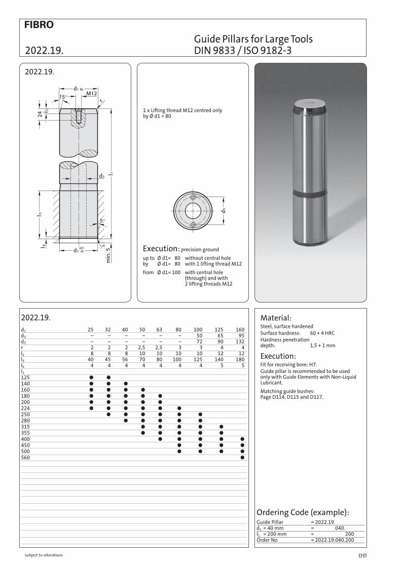
Guide Pillars for Large Tools 2022.19. DIN 9833 / ISO 9182-3
2022.19.
d1 25 32 40 50 63 80 100 125 160d3 – – – – – – 50 65 95d5 – – – – – – 72 90 132r 2 2 2 2,5 2,5 3 3 4 4l2 8 8 8 10 10 10 10 12 12l5 40 45 56 70 80 100 125 140 180l6 4 4 4 4 4 4 4 5 5l1
125 140 160 180 200 224 250 280 315 355 400 450 500 560
Material:Steel, surface hardenedSurface hardness: 60 + 4 HRCHardness penetration depth: 1,5 + 1 mm
Execution:Fit for receiving bore: H7.Guide pillar is recommended to be used only with Guide Elements with Non-Liquid Lubricant.
Matching guide bushes: Page D114, D115 and D117.
2022.19.
Ordering Code (example): Guide Pillar = 2022.19.d1 = 40 mm = 040.l1 = 200 mm = 200Order No = 2022.19.040.200
1 x Lifting thread M12 centred only by Ø d1 = 80
Execution: precision ground
up to Ø d1= 80 without central hole by Ø d1= 80 with 1 lifting thread M12
from Ø d1= 100 with central hole (through) and with 2 lifting threads M12
subject to alterations D31

Material:Steel, surface hardened
Surface hardness: 60 + 4 HRC
Hardness penetration depth: 1.5 + 1 mm
Execution:precision ground
*by d1 = 80 with 1 centered lifting thread M12
Note:Fit for receiving bore H6
Guide pillar is recommended to be used only with Guide Elements with Non-Liquid Lubricant.
Matching guide bushes: Page D114, D115 and D117.
Application:floating support in upper half of trimming tools.
2022.13.
2022.13. d1 40 50 63 80 d2 40 50 63 80 l5 56 70 80 100 l6 4 4 4 4 r 2 2,5 2,5 3 r1 3 5 6 8l1
140 160 180 200 224 250 280 315 355 400
Ordering Code (example):Guide Pillar = 2022.13.d1 = 40 mm = 040.l1 = 200 mm = 200Order No = 2022.13.040.200
Mounting Example:
Guide Pillar with 5° Pilot Taper to VW Standard 2022.13.
*
subject to alterationsD32

Guide Pillar with Groove 2022.16.45. to CNOMO
2022.16.45. d1 80 100 -0,010 -0,010 -0,025 -0,025 d2 80 100 +0,050 +0,055 +0,040 +0,045 d6 75 95 l2 16 16 l6 110 140l1
350 400 450
2022.16.45.
Material:Steel, surface hardenedSurface hardness: 60 + 3 HRCHardness penetration depth: 2 + 1.6 mm
Execution:precision ground
Note:Fit for receiving bore H7
Guide pillar is recommended to be used only with Guide Elements with Non-Liquid Lubricant.
Matching guide bushes: Page D114, D115 and D117 .
Mounting Example:
Ordering Code (example):Guide Pillar = 2022.16.45.d1 = 80 mm = 080.l1 = 350 mm = 350Order No = 2022.16.45.080.350
tol.
tol.
subject to alterations D33
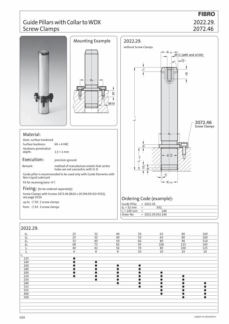
Guide Pillars with Collar to WDX 2022.29. Screw Clamps 2072.46
Material:Steel, surface hardened
Surface hardness: 60 + 4 HRC
Hardness penetration depth: 1,5 + 1 mm
Execution: precision ground
Remark: method of manufacture entails that centre holes are not concentric with O. D.
Guide pillar is recommended to be used only with Guide Elements with Non-Liquid Lubricant
Fit for receiving bore: H 7.
Fixing: (to be ordered separately)
Screw Clamps with Screws 2072.46 (M10 x 20 DIN EN ISO 4762), see page D216
up to [ 50 2 screw clamps
from [ 63 3 screw clamps
2022.29.without Screw Clamps
2022.29. d1 25 32 40 50 63 80 100 d2 25 32 40 50 63 80 100 d3 32 40 50 60 80 90 110 d6 68 75 83 93 106 123 143 l2 40 42 56 70 80 100 125 l3 6 8 8 10 10 10 10l1 125 140 160 180 200 224 250 280 315 355 400 500
Ordering Code (example):Guide Pillar = 2022.29.d1 = 32 mm = 032.l1 = 140 mm = 140Order No = 2022.29.032.140
Mounting Example
subject to alterationsD34

2021.46./2021.44./2021.43. d1 15 16 19 20 24 25 30 32 38 40 48 50 60 63 80 d2 15 16 19 20 24 25 30 32 38 40 48 50 60 63 80 d3 22 25 32 40 50 63 80 95 d5 22 25 32 40 50 60 70 93 d6 33 36 43 51 61 74 91 106 d7 45,7 48,7 55,7 63,7 73,7 86,7 103,7 118,7 a 15,9 16,6 18,4 20,4 29,2 33,8 39,8 46,2 a1 21,7 23 26 29,5 29,2 33,8 39,8 46,2 m M8 M8 M8 M8 M8 M8 M8 M12 s 6 6 6 6 6 6 6 12 l2 20 23 30 37 37 47 47 60l1 100 112 125 140 160 180 200 224 250 280 315 355 400
Demountable Pillars DIN 9825/~ISO 9182-5 2021.44. 2021.46. with Collar and Screw Clamp Retention 2021.43. Disc with Screw for Central Retention
2021.46./2021.44.
Material: Steel, surface hardened
Core strength: 900 N/mm2
Surface Hardness: 60 + 3 HRC (induction hardened)
Hardness Penetration: 1,8 mm
Execution: fine precision ground
Note: method of manufacture entails that centre holes are not concentric with O. D.
Demountable pillars with collar are suited to applications where die sharpening requires dismantling and re-fitting.
2021.44.Demountable Pillar ([38–63) with Ball Cage Retainer
Dimensions of ball cage retainer: See 202.91., page D211.
Note: Colour Code Combinations/Clearances - see pages D 10 and D 11.
Tolerance range – yellow = .10 green = .20 red = .30
Ordering Code (example):Disc with Screw = 2021.43.d1 = 32 mm = 2021.43.032Order No = 2021.43.032
2021.43.Disc with Screw
Ordering Code (example):Demountable Pillar = 2021.46.d1 = 32 mm = 2021.46.032.l1 = 180 mm = 2021.46.032.180Tolerance range red = 2021.46.032.180.30Order No = 2021.46.032.180.30
207.45Screw Clamps, incl. Screws
Order-No for replacement parts
for Ø d1 = 38 and over: 4 screw clamps
2021.46.with Screw Clamps
2021.44.with Ball Cage Retainer
M6 x 20 similar DIN 6912 head Ø 13
Mounting Example
subject to alterations D35
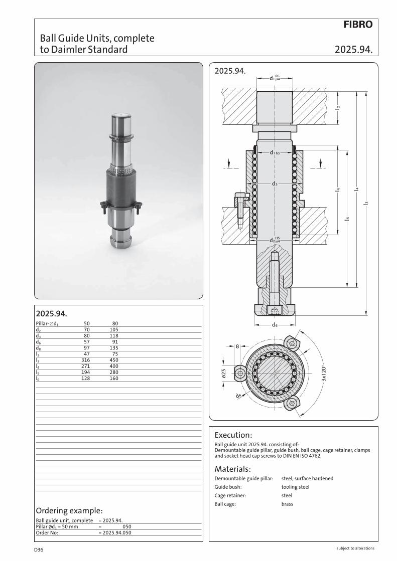
Ball Guide Units, complete to Daimler Standard 2025.94.
2025.94.
2025.94. 50 80d2 70 105d3 80 118d6 57 91d8 97 135l2 47 75l3 316 450l4 271 400l5 194 280l6 128 160
2025.94.Pillar- [d1
Ordering example:Ball guide unit, complete = 2025.94.Pillar Ød1 = 50 mm = 2025.94.050Order No: = 2025.94.050
Execution:Ball guide unit 2025.94. consisting of: Demountable guide pillar, guide bush, ball cage, cage retainer, clamps and socket head cap screws to DIN EN ISO 4762.
Materials:Demountable guide pillar: steel, surface hardened
Guide bush: tooling steel
Cage retainer: steel
Ball cage: brass
subject to alterationsD36

2021.29. Guide Pillars with Collar
2021.29.
2021.29. / 2021.43.
d1 15 16 19 20 24 25 30 32 38 40 48 50 60 63 80
d2 15 16 19 20 24 25 30 32 38 40 48 50 60 63 80
d3 22 25 32 40 50 63 80 95
d5 22 25 32 40 50 60 70 93
d6 33 36 43 51 61 74 91 106
d7 45,7 48,7 55,7 63,7 73,7 86,7 103,7 118,7
d8 24 27 34 42 52 62 72 95
a 15,9 16,6 18,4 20,4 29,2 33,8 39,8 46,2
a1 21,7 23 26 29,5 29,2 33,8 39,8 46,2
M M8 M8 M8 M8 M8 M8 M8 M12
s 6 6 6 6 6 6 6 12
l3 20,5 23,5 30,5 37,5 37,5 47,5 47,5 60,5
t5 6,5 6,5 6,5 6,5 6,5 6,5 6,5 12,5
l2 20 23 30 37 37 47 47 60
l1
100
112
125
140
160
180
200
224
250
280
315
355
400
2021.29.
Assembly of Guide Elements:
2021.43. Retaining Disc with Countersunk Socket Head Screw
2021.29.Material:Steel, surface hardened Surface hardness: 60 + 4 HRC
Hardness penetration depth: 1,5 + 1 mm
Note:Guide Pillar only recommended for use with sliding guides
Ordering Code (example):Disc with screw = 2021.43.
d1 = 32 mm = 032
Order No = 2021.43.032
207.45
Ordering Code (example):Guide Pillar with Collar = 2021.29.
d1 = 32 mm = 032.
l1 = 180 mm = 180
Order No = 2021.29.032.180
ECO-LINE
subject to alterations D37

206.41.Order No d l1 k206.41.012.020.021 12 21 2206.41.012.020.042 12 42 2206.41.012.025.021 12 21 2,5206.41.012.025.042 12 42 2,5206.41.015.030.045 15 45 3206.41.015.030.056 15 56 3206.41.015.030.063 15 63 3206.41.015.030.071 15 71 3
2062.44.012. forOrder No d d2 d3 l1 Ball Ø2062.44.012.016.032 12 16 20 32 22062.44.012.017.032 17 2,5
2061.44.015.Order No d d2 d3 l1 for Ball Ø2061.44.015.023.xx 15 21 28 23 32061.44.015.030.xx 302061.44.015.037.xx 372061.44.015.047.xx 472061.44.015.060.xx 60
206.41.
2062.44.012. 2061.44.015.
202.61.
Ball Guides for highest 206.41. 2061.44./2062.44. stroking speeds 202.61.
202.61Order No d1 d2 d3 l l1 l2
202.61.012.041.074 12 15,9 12,02 115 41 74202.61.015.044.080 15 23,5 15,02 124 44 80
Material:Cage: polyacetal tubing
Balls: Rolling bearing steel 100 Cr6 Quality Class 1, DIN 5401
Guide bush: tool steel, hardened to 62±2 HRC
Guide pillar: Steel, surface hardened
hardness penetration 1±0,2 mm
Discription:Owing to its much lower inertia, the plastic ball cage of particular advantage in die sets operating at stroking speed of 1000 SPM and more.
The phenomenon of ball-drag at the reversal point of cage travel, set up by the cage inertia, no longer occurs. The negative influence of this drag is eliminated – and so are the wear symptoms associated with it.
On small modular die sets the combination plastic ball cage/collared guide pillar 202.61. has indeed been successful for several years.
Cages with ball sizes 2 mm, 2,5 and 3 mm are supplied with matching guide bushes.
Tolerance range xx yellow = .10 green = .20
subject to alterationsD38

Demountable Guide Pillars, 2020.63. with centre fixing
2020.63.
Description:For press fit into register bore N5.
The transverse load resistance of tool guides is greatly influenced by the position of the guide pillar fixing.
For a tool with a spring-mounted die guide plate and pillar fixing at the top or bottom of the tool, the deflection and pillar bending values do not differ when the load is applied at the side since the distance (L) from the point of application of the force is the same.
Significantly better pillar bending values can be achieved by fixing the guide pillars in the die guide plate, i.e. in the centre of the pillar.
Since the distance ( ) between the point of application of the
force and the fixing surface is thus halved, the load-bearing capacity is increased by eight times.
2020.63.d1 12 16d2 13 18d5 15,9 21,9l1 116 158l2 42 64l3 74 94l4 12,5 16l5 5 8l6 3 5
Ordering Code (example):Demountable Guide Pillars = 2020.63.d1 = 12 mm = 2020.63.012.l2 = 42 mm = 2020.63.012.042.l3 = 74 mm = 2020.63.012.043.074Order No = 2020.63.012.042.074
Material: Steel, surface hardened
surface hardness: 62+2 HRC case hardened
hardness penetration: 1 ± 0,2 mm
L2
Mounting Example:
subject to alterations D39

2020.62.d1 d2 d3 d4 d6 d7 t l1 l2 l3 l4 l5 l6
12 28 20 13 6 3,4 3,4 90 40 50 12 6 3 100 40 60 110 50 60 120 50 70 130 60 70 140 70 7016 38 28 18 8 4,5 4,6 140 60 80 16 8 4 150 60 90 160 70 90 170 70 100 180 80 100 190 90 10019 42 32 22 8 4,5 4,6 160 70 90 20 8 4 170 70 100 180 80 100 190 80 110 200 90 110 210 100 11025 48 38 26 8 4,5 4,6 180 80 100 22 8 6 190 80 110 200 90 110 210 90 120 220 100 120 230 110 12032 60 48 34 10 5,5 5,7 180 80 100 25 10 7 190 80 110 200 90 110 210 90 120 220 100 120 230 100 130 240 110 130 250 110 14040 70 56 42 11 6,6 6,8 200 90 110 27 12 7 210 90 120 220 100 120 230 100 130 240 110 130 250 110 140 260 120 140
2020.62.
Stripper-Mounted Pillars 2020.62.
Mounting Example
Material: Steel, heat treatedCore strength: ^ 900 N/mm2
Surface Hardness: 60+ 3 HRC (induction hardened)Hardness Penetration: ^ 2,0 + 1,6 mm
Execution: precision ground
Note: Use hexagon socket head cap screws DIN EN ISO 4762 12.9
Colour Code Combinations/Clearances – see pages D 10 and D 11.
Diameter 12 only available in Tolerance range yellow = .10
Ordering Code (example):Stripper-Mounted Pillar with centre fixing = 2020.62.d1 = 12 mm = 012.l2 = 50 mm = 050.l3 = 60 mm = 060.Tolerance range – yellow = 10Order No = 2020.62.012.050.060.10
Tolerance range yellow = .10 green = .20 red = .30
Description:The transverse load resistance of tool guides is greatly influenced by the position of the guide pillar fixing.
For a tool with a spring-mounted die guide plate and pillar fixing at the top or bottom of the tool, the deflection and pillar bending values do not differ when the load is applied at the side since the distance (L) from the point of application of the force is the same.
Significantly better pillar bending values can be achieved by fixing the guide pillars in the die guide plate, i.e. in the centre of the pillar.
Since the distance ( ) between the point of application of the
force and the fixing surface is thus halved, the load-bearing capacity is increased by eight times.
L2
subject to alterationsD40

202.60. Stripper-Mounted Pillars
202.60.Stripper-Mounted Pillars with ring nut
202.60.d1 19 25 32 40d2 32 38 46 56d3 25 30 36 46d4 M22 3 1,5 M28 3 1,5 M35 3 1,5 M45 3 1,5d5 8 12 20 28d6 40 50 55 68h 9 10 11 12l2 80 80 100 100l3 120 120 140 140l4 29 29 34 34l5 45 45 50 50 Shorter lengths l2 and l3 available on request
Material: Steel, surface hardened
Core strength: ^ 900 N/mm2
Surface Hardness: 60 + 3 HRC (induction hardened)
Hardness Penetration: ^ 1,8 mm
Execution: precision ground
Note: Colour Code Combinations/Clearances – see pages D10 and D11.
Mounting Examle
Ordering Code (example):Stripper-Mounted Pillar with Collarand ring nut retention = 202.60.d1 = 25 mm = 202.60.025.l2 = 80 mm = 202.60.025.080.l3 = 120 mm = 202.60.025.080.120.Tolerance range – green = 20Order No = 202.60.025.080.120.20
Ordering Code ring nut only
(example): to DIN 1804-h = 202.60. 0 2 5
d1
Always use shouldered face as bearing surface!
Tolerance range yellow = .10 green = .20 red = .30
Description:The transverse load resistance of tool guides is greatly influenced by the position of the guide pillar fixing.
For a tool with a spring-mounted die guide plate and pillar fixing at the top or bottom of the tool, the deflection and pillar bending values do not differ when the load is applied at the side since the distance (L) from the point of application of the force is the same.
Significantly better pillar bending values can be achieved by fixing the guide pillars in the die guide plate, i.e. in the centre of the pillar.
Since the distance ( ) between the point of application of the
force and the fixing surface is thus halved, the load-bearing capacity is increased by eight times.
In order to keep moving mass to a minimum and thereby minimize detrimental forces of inertia, FIBRO Stripper-Mounted Pillars are made with a hollow core. Rigidity of the die set – of paramount importance – remains unaffected by the hollow design.
L2
subject to alterations D41

2021.64.d1 25,5 32,5d2 M35 3 1,5 M40 3 1,5d3 37 44d5 43 50d6 27,86 34,86d8 55 62h 11 12 Available upon request!
Mounting Example:
2073.48.DIN 1804
Stripper-Mounted Retaining Bushes, conical pillar fit 2021.64.
2021.64.
Material: Retaining bushes 16 MnCr5
Surface hardness: Case hardened 60 ±2 HRC
Hardness Penetration: ^ 0,8 –1 mm
Execution: Thread not hardened
Note: Guide pillar 2020.64.
Ordering Code (example):Retaining Bush, conical = 2021.64.d1 = 32 mm = 032Order No = 2021.64.032
Ordering Code (example):Ring Nut = 2073.48.d2 = M40 1,5 = 2073.48.040.15Order No = 2073.48.040.15
subject to alterationsD42
2020.64.d1 d2 d3 d4 k l2 l3 l4 l5
25 70 55 27,86 26 102 143 102 41 122 143 102 4132 76 62 34,86 30 102 143 102 41 122 143 102 41 122 153 112 41 137 153 112 41 142 153 112 41 162 153 112 41 Available upon request!
Description:The transverse load resistance of tool guides is greatly influenced by the position of the guide pillar fixing.
For a tool with a spring-mounted die guide plate and pillar fixing at the top or bottom of the tool, the deflection and pillar bending values do not differ when the load is applied at the side since the distance (L) from the point of application of the force is the same.
Significantly better pillar bending values can be achieved by fixing the guide pillars in the die guide plate, i.e. in the centre of the pillar.
Since the distance ( ) between the point of application of the
force and the fixing surface is thus halved, the load-bearing capacity is increased by eight times.
Stripper Mounted Guide Pillars 2020.64. conical, with centre fixing
Material:Steel hardened to 62±2 HRC
Execution:Precision ground
Note:Retaining Bush 2021.64.
Use screws conforming to DIN EN ISO 4762 12.9
Tolerance range yellow = .10 green = .20
Ordering Code (example):Guide Pillar, conicalwith centre fixing = 2020.64.d1 = 25 mm = 025.l2 = 102 mm = 102.l3 = 143 mm = 102.143.Tolerance range – yellow = 143.10Order No = 2020.64.025.102.143.10
Mounting Example:2020.64.
L2
subject to alterations D43

Million Guide - Guide Units 2024.94.
2024.94.2024.94.
Cross section of guide unit
[ 16 4 Running surfaces [ 12, [ 20 - [ 60 6 Running surfaces [ 80 8 Running surfaces
The secret of the high rigidity, robustness and guide accuracy of FIBRO Million Guide guide units is the large surface area of the needle rollers.
subject to alterationsD44

2024.94.d1 12 16 20 25 30 32 40 50 060 080d2 12 16 20 25 30 32 40 50 060 080d3 18 24 29 35 40 42 54 64 074 098d4 16 22 26 32 38 40 50 60 072 105d5 18 24 28 34 38 40 50 60 072 105d6 23 30 37 44 50 54 68 78 095 120m M5x8 M6x10 M8x20 M8x20 M10x25 M10x25 M12x30 M12x30 M14x30 M16x30l2 12 16 20 25 30 30 35 35 042 045l3 06 06 08 08 08 08 08 08 015 015l4 07 10 13 13 16 16 18 18 020 026l5 03 04 05 05 07 07 09 09 012 013l6 05 06 08 08 09 09 10 12 015 015l7 29,8 30 52 62 68 68 78 82 116 132l8 40 40 60 70 78 78 92 96 120 145l9 – – 20 20 20 20 20 20 020 025l1 050 060 070 080 090 100 110 120 130 140 150 160 170 180 190 200 210 220 230 240 250 260 270 280
Ordering Code (example):Guide unitMillion Guide = 2024.94.d1 = 20 mm = 2024.94.020.l1 = 120 mm = 2024.94.020.120Order No = 2024.94.020.120
2024.94. Million Guide - Guide Units
Description:FIBRO Million Guide guide units are used wherever rigidity, robustness and a precision guide function is required. For stroke speeds up to 50 m/min and temperatures up to 80 °C.
Version:Guide unit 2024.94 consisting of paired guide pillar and guide sleeve, needle roller cage and disk for fixing the guide column. The fixing screw is ordered separately (see C40, C41) as the screw required depends on the thickness of the base plate.
Materials:Needle roller cage: plastic
Needle rollers: steel, hardened
Guide sleeve: tool steel alloy, hardened, 60±2 HRC
Guide pillar: tool steel alloy, hardened, 60±2 HRC
Disk: Steel
Note:Guide units must be installed in accordance with the Instructions.
subject to alterations D45

Million Guide - Guide Units 2024.96.
2024.96.
Cross section of guide unit
[ 16 4 Running surfaces [ 12, [ 20 - [ 30 6 Running surfaces
The secret of the high rigidity, robustness and guide accuracy of FIBRO Million Guide guide units is the large surface area of the needle rollers.
2024.96.
subject to alterationsD46

2024.96. Million Guide - Guide Units
2024.96.d1 12 16 20 25 30d2 12,5 16,5 20,5 25,5 30,5d3 19 23 27 32 37d6 22 28 34 40 48m M5x8 M6x10 M8x20 M8x20 M8x20l4 12 16 20 25 30l6 04 05 05 05 05l7 29,8 30 46 56 68l8 30 40 50 60 70l9 – – 20 20 20 l2 l2 l2 l2 l2
l3 050 40/50/60 060 40/50/60 070 40/50/60 40/50/60 080 40/50/60/70 50/60/70 090 50/60/70/80 50/60/70/80 60/70/80 70/80/90 100 60/70/80/90 60/70/80/90 70/80/90 110 70/80/90 70/80/90
Description:FIBRO Million Guide guide units are used wherever rigidity, robustness and a precision guide function is required. For stroke speeds up to 50 m/min and temperatures up to 80 °C.
Version:Guide unit consisting of a paired guide pillar & guide sleeves and needle roller cages.
Materials:Needle roller cage: plastic
Needle rollers: steel, hardened
Guide sleeve: tool steel alloy, hardened, 60±2 HRC
Guide pillar: tool steel alloy, hardened, 60±2 HRC
Disk: Steel
Note:Guide units must be installed in accordance with the Instructions.
Ordering Code (example):Million Guide – guide unit with centre fixing = 2024.96.d1 = 20 mm = 2024.96.020.l3 = 80 mm = 2024.96.020.080.l2 = 70 mm = 2024.96.020.080.070Order No = 2024.96.020.080.070
subject to alterations D47

Mounting examples:
Rectangular Mounting Flanges Bronze with Non-Liquid Lubricant 2031.70.
2031.70.
2031.70.d1 19 20 24 25 30 32 38 40 50 63 80d3 45 45 50 50 65 65 80 80 96 110 130d4 9 9 9 9 11 11 14 14 18 18 22a 85 85 90 90 115 115 130 130 160 180 215b 45 45 50 50 65 65 80 80 96 110 130e1 64 64 68 68 83 83 95 95 118 132 160e2 24 24 28 28 34 34 45 45 55 62 75h 18 18 22 22 25 25 30 30 35 35 40h1 37 37 47 47 60 60 77 77 95 120 120t1 3 3 3 3 3 3 3 3 4 4 10
Material:Mounting flange – special cast iron Guide bush 2052.70. Bronze, with non-liquid lubricant.
Execution:Face and top machined.
Ordering Code (example):Mounting Flange, Guide Bush with Non-Liquid Lubricant 2052.70. = 2031.70.d1 = 40 mm = 040Order No = 2031.70.040
*202.19. Guide pillars *2022.19. *2021.46. * 202.19. *2022.25. *2021.43.
* Guide pillars, to order separately, see pages D16, D26, D31, and D35.
subject to alterationsD48

2031.01./2031.31./2031.41. d1 15 16 19 20 24 25 30 32 38 40 48 50 60 63 80 d2 21 22 25 26 30 31 38 40 46 48 56 58 68 71 – d3 35 45 50 65 80 96 110 130 a 70 85 90 115 130 160 180 215 b 35 45 50 65 80 96 110 130 h 18 18 22 25 30 35 35 40 h1 30 37 47 60 77 95 120 120 l* 45 45 56 71 95 120 140 – l1* 44 44 56 70 95 120 140 – l* = Nominal ordering lengthl1* = Manufacturing length = Preferred lengths of Ball Cages
Rectangular Mounting Flanges 2031.01./.31./.41. – without screw holes – 206.71. Ball Cages
2031.31.Mounting Flange with Sintered Ferrite Guide Bush, carbonitrided
2031.41.Mounting Flange with Ball Bearing Guide Bush
to be ordered separately: Ball Cage 206.71.
2031.01.Mounting Flange for Guide Pillars
Mounting Examples:
Material:Special cast iron
Execution:Mounting Flanges for Guide Bushes: Face and top machined. Bores honed.
Mounting Flanges for Guide Pillars: Face and top machined. Hole fine bored to d1
R6 fit.
Note:Check squareness of pillars after press-fitting. Notes on Sliding-/Ball Bearing Guides – see page D 9.
*Guide Pillars, to order separate, see pages D16 and D35.
Guide Pillars *202.19.
*202.19.
*2021.46. *2021.43.
Ordering Code (example):Mounting Flange with sinteredferrite guide bush = 2031.31.d1 = 32 mm = 032.Tolerance range – red = 30Order No = 2031.31.032.30
Ball Cage = 206.71.d1 = 32 mm = 206.71.032.l = 71 mm = 206.71.032.071Order No = 206.71.032.071
Mounting flangefor Guide Pillars = 2031.01.d1 = 40 mm = 2031.71.040Order No = 2031.01.040
Tolerance range – yellow = .10 green = .20 red = .30
*Colour Code Combinations/Clearances – see pages D 10 and D 11.
subject to alterations D49

2031.02./2031.34./2031.42. d1 15 16 19 20 24 25 30 32 38 40 48 50 60 63 80 d2 21 22 25 26 30 31 38 40 46 48 56 58 68 71 – d3 35 45 50 65 80 96 110 130 d4 6,6 9 9 11 14 18 18 22 t1 3 3 3 3 3 4 4 10 a 70 85 90 115 130 160 180 215 b 35 45 50 65 80 96 110 130 e1 53 64 68 83 95 118 132 160 e2 19 24 28 34 45 55 62 75 h 18 18 22 25 30 35 35 40 h1 30 37 47 60 77 95 120 120 l* 45 45 56 71 95 120 140 – l1* 44 44 56 70 95 120 140 – l* = Nominal ordering lengthl1* = Manufacturing length = Preferred lengths of Ball Cages
Ordering code (example):Mounting Flange for Ball Bearing Guide = 2031.42.d1 = 40 mm = 040.Tolerance range – green = 20Order No = 2031.42.040.20
Rectangular Mounting Flanges 2031.02./.34./.42. Ball Cages 206.71.
2031.34.Mounting Flange with Sintered Ferrite Guide Bush, carbonitrided
2031.42.Mounting Flange for Ball Bearing Guide
2031.02.Mounting Flange for Guide Pillars
*Colour Code Combinations/Clearances – see pages D10 and D11.
Mounting Examples:
Material:Special cast iron
Execution:Mounting Flanges for Guide Bushes: Face and top machined. Bores honed.
Mounting Flanges for Guide Pillars: Face and top machined. Hole fine bored to d1
R6 – fit.
Note:Check squareness of pillars after press-fitting. Notes on Sliding-/Ball Bearing Guides – see page D 9.
* Guide Pillars, to order separate, see pages D16 and D35.
Guide Pillars *202.19.
*202.19.
*2021.46. *2021.43.
to be ordered separately: Ball Cage 206.71.
Tolerance range – yellow = .10 green = .20 red = .30
Ball Cage = 206.71.d1 = 40 mm = 206.71.040.l = 95 mm = 206.71.032.095Order No = 206.71.040.095
Mounting flangefor Guide Pillars = 2031.02.d1 = 40 mm = 2031.71.040Order No = 2031.02.040
subject to alterationsD50

2031.04./2031.38./2031.44. d1 15 16 19 20 24 25 30 32 38 40 48 50 60 63 80 d2 – 25 26 30 31 38 40 46 48 56 58 – – d3 32 42 47 62 77 93 107 127 d4 7 9 9 11 14 18 18 22 a 70 85 90 115 130 160 180 215 b 35 45 50 65 80 96 110 130 e1 53 64 68 83 95 118 132 160 e2 19 24 28 34 45 55 62 75 h 16 16 20 23 28 33 33 38 h1 30 37 47 60 77 95 120 120 l* – 45 56 71 95 120 – – l1* – 44 56 70 95 120 – – l* = Nominal ordering lengthl1* = Manufacturing length = Preferred lengths of Ball Cages
Ordering Code (example):Mounting Flange for Ball Bearing Guide = 2031.44.d1 = 40 mm = 040.Tolerance range – yellow = 10Order No = 2031.44.040.10
Tolerance range – yellow = .10 green = .20 red = .30
Shallow Mounting Flanges 2031.04./.38./.44. – Rectangular – 206.71. Ball Cages
2031.38.Mounting Flange with Sintered Ferrite Guide Bush, carbonitrided
2031.44.Mounting Flange for Ball Bearing Guide
2031.04.Mounting Flange for Guide Pillars
*Colour Code Combinations/Clearances – see pages D 10 and D 11.
Mounting Examples:
Material:Special cast iron
Execution:Both faces machined to dims. h; O. D. d3 turned.
Mounting Flange for Guide Bushes: Bores honed.
Mounting Flanges for Guide Pillars: Hole fine bored to d1
R6 – fit.
Note:Check squareness of pillars after press-fitting.
*Guide Pillars, to order separate, see pages D16 and D35.
Guide Pillars *202.19.
*202.19.
*2021.46. *2021.43.
to be ordered separately: Ball Cage 206.71.
Ball Cage = 206.71.d1 = 40 mm = 206.71.040.l = 95 mm = 206.71.032.095Order No = 206.71.040.095
Mounting flangefor Guide Pillars = 2031.04.d1 = 40 mm = 2031.71.040Order No = 2031.04.040
Notes on Sliding-/Ball Bearing Guides – see page D9.
subject to alterations D51
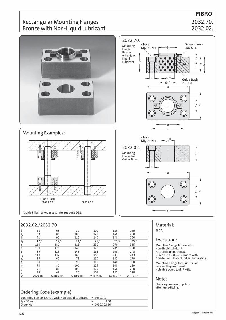
Rectangular Mounting Flanges Bronze with Non-Liquid Lubricant
2032.70.Mounting Flange Bronze with Non- Liquid Lubricant
2032.02.Mounting Flange for Guide Pillars
Mounting Examples:
* Guide Pillars, to order separate, see page D31.
Material:St 37.
Execution:Mounting Flange Bronze with Non-Liquid Lubricant: Face and top machined. Guide Bush 2082.70. Bronze with Non-Liquid Lubricant, oilless lubricating.
Mounting Flange for Guide Pillars: Face and top machined. Hole fine bored to d1
H7 – fit.
Note:Check squareness of pillars after press-fitting.
2032.02./2032.70d1 50 63 80 100 125 160d2 63 80 100 125 160 200d3 71 90 112 140 180 220d6 17,5 17,5 21,5 21,5 25,5 25,5a 160 180 215 230 270 315b 100 125 145 170 205 250e 89 123 143 168 203 243e1 118 132 160 168 203 243e2 55 62 75 110 142 170h 60 70 90 110 140 180h1 70 80 100 125 140 180l1 71 80 100 125 160 200l2 56 63 80 106 132 170M M6 x 16 M10 x 16 M10 x 16 M10 x 16 M10 x 16 M10 x 16
Ordering Code (example):Mounting Flange, Bronze with Non-Liquid Lubricant = 2032.70.d1 = 50 mm = 050Order No = 2032.70.050
Guide Bush *2022.19. *2022.19.
2032.70. 2032.02.
subject to alterationsD52

subject to alterations D53

2051.32.d1 8 11 12 15 16 19 20 24 25 30 32 38 40 48 50 60 63 80
d3 13,7 22 28 32 40 48 58 70 85 95,7
l1 15
23
30
37
47
60
77
95
110
120
Ordering Code (example):Guide Bush DIN 9831/ISO 9448-2 = 2051.32.d1 = 40 mm = 040.l1 = 60 mm = 060.Tolerance range – red = 30Order No = 2051.32.040.060.30
Guide Bushes DIN 9831/ISO 9448-2 Sintered Ferrite, carbonitrided, long-term lubrication 2051.32.
2051.32.for slip-fit bonding
* Colour Code Combinations/Clearances – see pages D10 and D11.
Material:Sintered ferrite of high purity, carbonitrided
Execution:Bearing surfaces and outside diameter fine-ground.
Slip-Fit Bonding:The position of the bearing is given by push fit holes tolerance H5. The adhesive (order no. 281.648) provides optimum push retention whilst offering the following advantages:
– high accuracy and stiffness – no problems to find position when changing bushings
We do not recommend to press fit for the same reasons mentioned above.
Note:Notes on Sliding- and Ball Bearings Guides: see page D9.
Pillars see pages D14, D16, D17, D18, D22 and D35.
Tolerance range – yellow = .10 green = .20 red = .30
[8–[12 not available
in Tolerance range red = .30
subject to alterationsD54
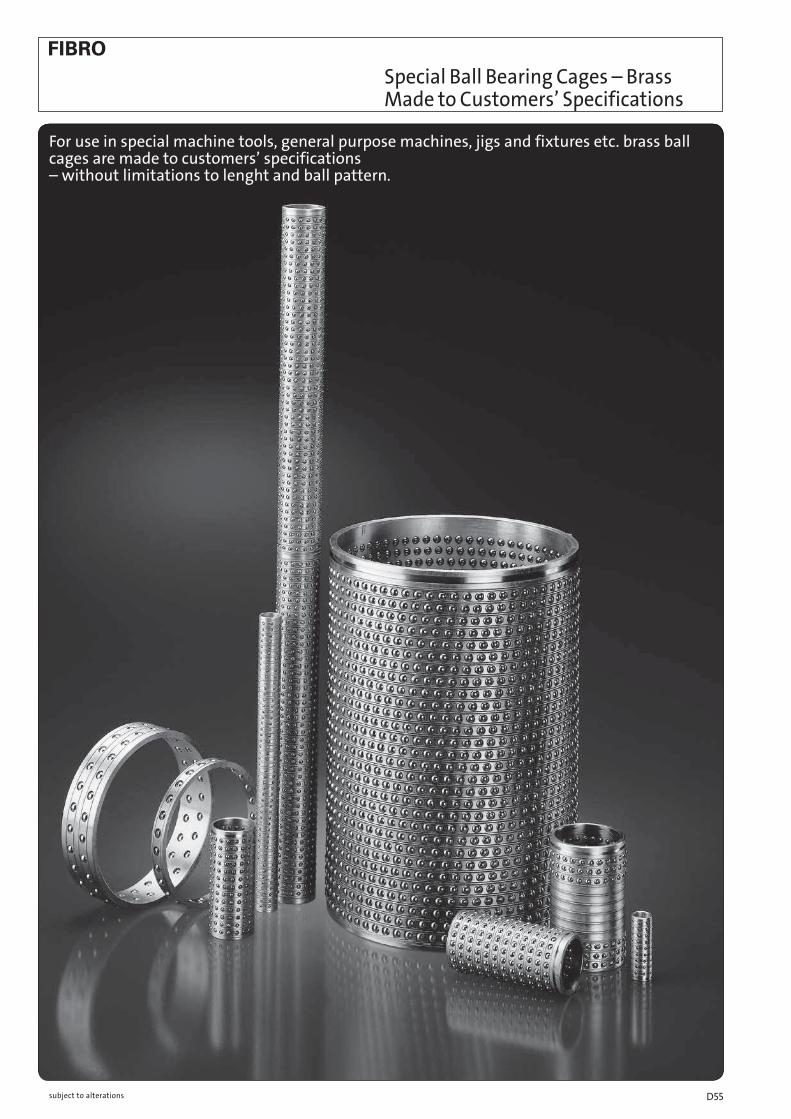
Special Ball Bearing Cages – Brass Made to Customers’ Specifications
For use in special machine tools, general purpose machines, jigs and fixtures etc. brass ball cages are made to customers’ specifications – without limitations to lenght and ball pattern.
subject to alterations D55
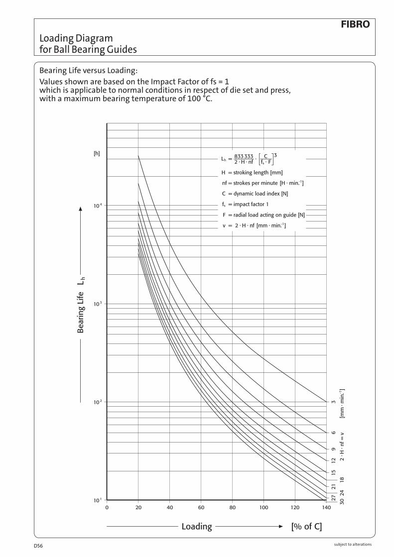
Loading Diagram for Ball Bearing Guides
Bearing Life versus Loading:
Values shown are based on the Impact Factor of fs = 1 which is applicable to normal conditions in respect of die set and press, with a maximum bearing temperature of 100 °C.
subject to alterationsD56

Safe Loads for FIBRO Ball Bearing Guides
Dynamic Load Index C Pillar [ d1 Cage length l1 for whole cage (N) 8 40 450 10 40 1630 56 2210 11 40 1660 56 2250 12 40 1680 56 2280 15 45 3300 56 4050 63 4550 71 4950 16 24 1910 28 2230 45 3350 56 4100 63 4600 71 5000 19 31 3050 45 4050 56 4950 71 6100 80 6600 95 7600 20 24 2320 28 2700 31 3100 45 4100 56 5000 71 6100 80 6600 95 7600 24 31 3150 40 3850 45 4200 56 5100 71 6300 80 6800 95 7800 120 9300 25 31 3200 40 3900 45 4200 56 5200 71 6300 80 6900 95 7900 120 9300 30 40 5700 45 6400 50 7000 56 7600 71 9300 75 9800 80 10400 95 11900 105 12800 120 14200 140 16000 160 17700 32 40 5800 45 6400 50 7100 56 7700 71 9400 75 9900 80 10500 95 12000 105 12900 120 14300 140 16100 160 17800
Dynamic Load Index C Pillar [ d1 Cage length l1 for whole cage (N) 38 45 7500 50 8200 56 8900 63 10300 80 12100 95 13900 105 15000 120 16700 140 18700 160 20700 180 22600 200 24400 240 28000 40 45 7500 50 8200 56 9000 63 10300 80 12200 95 14000 105 15100 120 16700 140 18800 160 20800 180 22700 200 24600 240 28000 48 50 9400 63 11700 80 13800 95 15900 105 17100 120 19000 140 21400 160 23600 180 26000 200 28000 240 32000 50 50 9400 63 11700 80 13900 95 15900 105 17200 120 19100 140 21400 160 23700 180 26000 200 28000 240 32000 60 95 17700 105 19200 120 21300 140 23900 160 26500 180 29000 200 31000 240 35500 63 95 17800 105 19300 120 21300 140 24000 160 26500 180 29000 200 31500 240 35500 80 120 41000 140 46500 160 52000 180 57000 200 62000 240 70000
Tables of Dynamic Load IndexesDefinition: The dynamic load index C constitutes a constant loading that will allow the respective sizes of ball bearing guides to reach + 105 m without any discernible bearing damage. The load index is shown in N and results from tests executed with batches of sufficient size, subjected to linear travel oscillations and radially imposed loads of constant magnitude and unchanging direction.
subject to alterations D57

2061.44.
d1 8* 10 11 12 15 16 19 20 24 25 30 32 38 40 48 50 60 63 80d2 11 14 15 16 21 22 25 26 30 31 38 40 46 48 56 58 68 71 92d3 18 22 22 22 28 28 32 32 40 40 48 48 58 58 70 70 85 85 105l1 l* l2*23 40 39 23 45 44 30 40 39 30 45 44 30 45 45 37 40 39 37 45 44 37 50 50 47 56 55 47 56 56 47 63 55 60 71 70 60 71 72 60 80 80 60 95 95 77 95 95 77 95 96 95 120 120 120 140 140
Ball Bearing Guide Bushes DIN 9831/ISO 9448-3 Ball Cages
2061.44.
Material:Bush: tool steel, Hardness: 62 ± 2HRC Cage: brass Balls: hardened steel (DIN 5401)
Execution:Bearing surfaces honed. Outside diameter fine-ground.
Slip-Fit Bonding:The position of the bearing is given by push fit holes tolerance H5. The adhesive (order no. 281.648) provides optimum push retention whilst offering the following advantages:
– high accuracy and stiffness
– no problems to find position when changing bushings
We do not recommend to press fit for the same reasons mentioned above.
Note:Notes on sliding- and rolling type guides see page D9.
Pillars see pages D14, D16, D17, D18, D22 and D35.
Ordering Code (example):
Guide Bush = 2061.44.d1 = 30 mm = 030.l1 = 95 mm = 095.Tolerance range – yellow = 10Order No = 2061.44.030.095.10
Ordering Code (example):
Ball Cage = 206.71.d1 = 30 mm = 206.71.030.l2 = 120 mm = 206.71.030.120Order No = 206.71.030.120
* Preloading see Colour Code Combinations – pages D 10 and D 11.
* Ball cages Ø8 supplied without fastening ring groove and assembly aid!
Note: cage travel = one half of stroke length
l* = Nominal ordering length
l2* = Manufacturing length = Preferred lengths of Ball Cages
Tolerance range – yellow = .10 green = .20 red = .30
to be ordered separately: Ball Cage 206.71.
Diameter 8–12 not available
in Tolerance range red = .30
2061.44. 206.71.
subject to alterationsD58

206.49./206.71.d1 16 20 25 32 40 50d2 22 26 31 40 48 58d3m5 28 32 40 50 63 80l1 l* l2* 35 45 44 ● ● 40 45 44 ● ● ● 45 56 55 ● 50 56 56 ● ● ● 55 63 65 ● 60 71 70 ● 60 71 72 ● ● ● 70 80 80 ● ● ● ● ● 80 95 95 ● ● ● 80 95 96 ● ● 90 95 96 ● 90 105 105 ● ● ●100 120 120 ● ● ●120 140 140 ● ● Note: cage travel = one half of stroke lengthl* = Nominal ordering lengthl2* = Manufacturing length = Preferred lengths of Ball Cages
206.49.
Material:Bush: tool steel, Hardness: 62 ± 2 HRC Cage: brass Balls: hardened steel (DIN 5401)
Execution:Bearing surfaces honed. Outside diameter fine-ground.
Note:Notes on sliding- and rolling type guides see page D9.
Pillars see pages D16, D17, D18, D22 and D35.
Slip-Fit Bonding:The position of the bearing is given by push fit holes tolerance H5. The adhesive (order no. 281.648) provides optimum push retention whilst offering the following advantages:
– high accuracy and stiffness – no problems to find position when changing bushings
We do not recommend to press fit for the same reasons mentioned above.
206.49. 206.71.
Mounting Examples
Ordering Code (example):Guide Bush = 206.49.d1 = 32 mm = 032.l1 = 90 mm = 090.Tolerance range green = 20Order No = 206.49.032.090.20
Ordering Code (example):Ball Cage = 206.71.d1 = 32 mm = 206.63.032.l2 = 105 mm = 206.63.032.105Order No = 206.71.032.105
* Preloading see Colour Code Combinations – pages D 10 and D 11.
to be ordered separately: Ball Cage 206.71.
Tolerance range – yellow = .10 green = .20 red = .30
Ball Bearing Guide Bushes similar to AFNOR Ball Cages
subject to alterations D59

206.72.Circlip to DIN 471
Ball Cages with Circlip Groove Circlips
206.71. Material:Cage: Brass
Balls: hardened steel (DIN 5401)
Execution: FIBRO Ball Cages are made from brass. They are distinguished by their stability and dense ball pattern. This makes them the pre ferred choice in tools and machines of high precision demands and ele vated stroking speeds. Ball guides operate free from play because of their accurate preloading.
Each ball cage has a groove for circlip to DIN 471.
206.71.d1 8* 10 11 12 15 16 19 20 24 25 30 32 38 40 48 50 60 63 80k 1,5 2 2 2 3 3 3 3 3 4 4 4 4 6n – 2,2 2,2 2,2 2,9 2,9 2,9 2,9 3,2 3,95 3,95 4,25 4,75 6,15l* l1* total number of balls 24 24 64 80 28 28 80 100 31 32 120 120 120 40 39 80 176 176 176 40 40 160 120 45 44 144 144 180 180 180 45 45 140 168 50 50 160 192 224 56 55 180 216 56 56 192 192 240 240 240 56 57 272 272 272 63 64 224 224 63 65 264 308 71 70 240 71 72 256 256 320 320 320 80 80 360 360 360 280 336 392 95 95 340 408 476 544 95 96 440 440 440 105 105 380 456 532 608120 119 540120 120 560 440 528 616 704 140 140 520 624 728 832 648160 160 600 720 840 960 160 161 756180 180 816 952 1088 180 182 864200 200 912 1064 1216 200 203 972240 238 1152240 240 1104 1288 1472 Note: cage travel = one half of stroke length * Ball cages Ø8 supplied without circlip groove !l* = Nominal ordering length l1* = Manufacturing length
Ordering Code(example):Ball Cage with Circlip Groove = 206.71.d1 = 32 mm = 206.71.032.l1 = 80 mm = 206.71.032.080Order No = 206.71.032.080
206.72.Order No206.72. 010 011 012 015 016 018 019 020 024 025 030 032 038 040 042 048 050 052 060 063 080d1 10 11 12 15 16 18 19 20 24 25 30 32 38 40 42 48 50 52 60 63 80da3s 1331 1431 1531 2031,2 2131,2 2331,2 2431,2 2531,2 2931,5 3031,5 3731,75 3931,75 4531,75 4731,75 4831,75 5532 5732 5832 6732,5 7032,5 9033d2 20,2 21,4 22,6 28,4 29,6 32 33,2 34,2 39,1 40,5 49 51,4 59,1 60,8 62,5 70,2 72,6 73,6 83,1 87 108,5
206.71. 206.72.
subject to alterationsD60

206.73.
Execution: FIBRO Ball Cages are made from brass. They are distinguished by their stability and dense ball pattern. This makes them the pre ferred choice in tools and machines of high precision demands and ele vated stroking speeds. Ball guides operate free from play because of their accurate preloading.
Ball Cages with Assembly Aid
Material:Cage: Brass
Balls: hardened steel (DIN 5401)
206.73. d1 10 11 12 15 16 19 20 24 25 30 32 38 40 48 50 60 63 80k 2 2 2 3 3 3 3 3 4 4 4 4 6l* l1* total number of balls 24 24 64 80 28 28 80 100 31 32 120 120 120 40 39 176 176 176 40 40 160 120 45 44 144 144 180 180 180 45 45 140 168 50 50 160 192 224 56 55 180 216 56 56 192 192 240 240 240 56 57 272 272 272 63 64 224 224 63 65 264 308 71 70 240 71 72 256 256 320 320 320 80 80 360 360 360 280 336 392 95 95 340 408 476 544 95 96 440 440 440 105 105 380 456 532 608 120 119 540120 120 560 440 528 616 704 140 140 520 624 728 832 648160 160 600 720 840 960 160 161 756180 180 816 952 1088 180 182 864200 200 912 1064 1216 200 203 972240 238 1152240 240 1104 1288 1472
Note: cage travel = one half of stroke lengthl* = Nominal ordering length l1* = Manufacturing length
Ordering Code (example):Ball Cage with Assembly Aid = 206.73.d1 = 32 mm = 206.71.032.l1 = 80 mm = 206.71.032.080Order No = 206.73.032.080
Note: Ball cages 206.73. with cage spacing.
These cages are held at the correct height for engaging the top die. These cages are equipped with a suitably positioned brake ring insert – ensuring equal cage spacing especially on die sets with multiple pillars. No assistant is needed for their assembly.
206.73.
subject to alterations D61

Ball Cages with Circlip and Fastening Ring Groove Circlips 206.75.
206.75.
Execution: FIBRO Ball Cages are made from brass. They are distinguished by their stability and dense ball pattern. This makes them the preferred choice in tools and machines of high precision demands and ele vated stroking speeds. Ball guides operate free from play because of their accurate preloading.
Each ball cage has a groove for circlip to DIN 472.
Material:Cage: Brass
Balls: hardened steel (DIN 5401)
206.75.d1 19 20 24 25 30 32 38 40 48 50 60 63di3s 2031 2131 2531,2 2631,2 3131,2 3331,2 3931,5 4131,75 5032 5132 6032 6332Order No.206.75. 019 020 024 025 030 032 038 040 048 050 060 063k 3 3 3 3 4 4 4 4 4 4 4 4n 1,3 1,3 1,3 1,3 1,3 1,3 1,85 1,6 2,15 2,15 2,15 2,15 l1 l2 l3 l1 l2 l3 l1 l2 l3 l1 l2 l3 l1 l2 l3 l1 l2 l3
56 2,6 31 56 2,6 31 70 2,6 41 80 3,45 51 80 4,30 51 95 4,30 61 72 41 72 41 80 51 95 61 95 61 120 73 80 51 80 51 95 61 105 61 120 73 140 83 105 61 120 73
Ordering Code (example):Ball Cages with CirclipDIN 472 and Fastening Ring Groove = 206.75.d1 = 32 mm = 206.75.032.l1 = 80 mm = 206.75.032.080.l3 = 51 mm = 206.75.03 051Order No = 206.75.032.080.051
subject to alterationsD62

2061.47.
* Preloading see Colour Code Combinations – pages D10 and D11.
Ball Bearing Guide Bushes 2061.47. with stroke Limitation 206.71. Ball Cages
Material:Bush: tool steel, Hardness: 62±2HRC Cage: Brass Balls: hardened steel (DIN 5401)
Slip-Fit Bonding:The position of the bearing is given by push fit holes tolerance H5. The adhesive oder no. 281.648 provides optimum push retention whilst offering the following advantages:
– high accuracy and stiffness
– no problems to find position when changing bushings
We do not recommend to press fir for the same reasons mentioned above.
Note:Notes on sliding- and rolling type guides see page D9.
Pillars see pages D16, D17, D18, D22 and D35.
2061.47. d1 15 16 19 20 24 25 30 32 38 40 48 50 60 63 d2 21 22 25 26 30 31 38 40 46 48 56 58 68 71 d3 28 28 32 32 40 40 48 48 58 58 70 70 85 85 l2* l* Stroke max. l1 44 45 18 60 ● ● 44 45 52 77 ● ● 44 45 49 ● ● 56 56 27 ● ● 50 50 74 95 ● ● 70 71 32 ● ● 65 63 98 120 ● ● 80 80 64 ● ●105 105 14 ● ● 80 80 62 ● ● 95 95 32 ● ● Note: cage travel = one half of stroke lengthl* = Nominal ordering lengthl2* = Manufacturing length = Preferred lengths of Ball Cages
Ordering Code (example):Guide Bush = 2061.47.d1 = 40 mm = 2061.47.040.l1 = 120 mm = 2061.47.040.120.Tolerance range – red = 2061.47.040.120.30Order No = 2061.47.040.120.30
Ordering Code (example):Ball cage = 206.71.d1 = 40 mm = 206.71.040.l = 63 mm = 206.71.040.063Order No = 206.71.040.063
Tolerance range – yellow = .10 green = .20 red = .30
subject to alterations D63
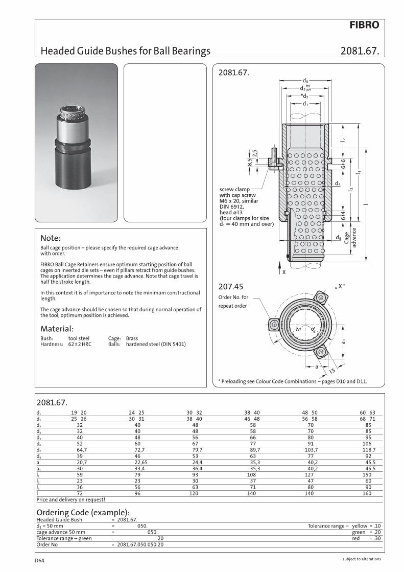
2081.67.
2081.67.d1 19 20 24 25 30 32 38 40 48 50 60 63d2 25 26 30 31 38 40 46 48 56 58 68 71d3 32 40 48 58 70 85d4 32 40 48 58 70 85d5 40 48 56 66 80 95d6 52 60 67 77 91 106d7 64,7 72,7 79,7 89,7 103,7 118,7d8 39 46 53 63 77 92a 20,7 22,65 24,4 35,3 40,2 45,5a1 30 33,4 36,4 35,3 40,2 45,5l1 59 79 93 108 127 150l2 23 23 30 37 47 60l3 36 56 63 71 80 90
l 72 96 120 140 140 160Price and delivery on request!
Ordering Code (example):Headed Guide Bush = 2081.67.d1 = 50 mm = 2081.67.050.cage advance 50 mm = 2081.67.050.050.Tolerance range – green = 2081.67.050.050.20Order No = 2081.67.050.050.20
* Preloading see Colour Code Combinations – pages D10 and D11.
Headed Guide Bushes for Ball Bearings 2081.67.
Note:Ball cage position – please specify the required cage advance with order.
FIBRO Ball Cage Retainers ensure optimum starting position of ball cages on inverted die sets – even if pillars retract from guide bushes. The application determines the cage advance. Note that cage travel is half the stroke length.
In this context it is of importance to note the minimum constructional length.
The cage advance should be chosen so that during normal operation of the tool, optimum position is achieved.
Material:Bush: tool steel Cage: Brass Hardness: 62±2 HRC Balls: hardened steel (DIN 5401)
207.45
Tolerance range – yellow = .10 green = .20 red = .30
Order No. for
repeat order
subject to alterationsD64

Flanged Guide Bushes for Ball Bearings 2091.67. with Ball Cage Retainer
2091.67.
* Preloading see Colour Code Combinations – pages D 10 and D 11.
2091.67.d1 19 20 24 25 30 32 38 40 48 50 60 63 80d2 25 26 30 31 38 40 46 48 56 58 68 71 92d3 32 40 48 58 70 85 105d4 50 63 72 85 104 120 148d5 40 50 58 70 86 100 125d6 4,5 5,5 5,5 6,6 9 9 11Counterbore Km 4 Km 5 Km 5 Km 6 Km 8 Km 8 Km 10k 18 23 28 33 38 46 56l1 52 62 72 77 102 102 125l2 37 37 47 47 60 60 75l3 15 25 25 30 42 42 50l 72 72 80 95 105 120 140 Price and delivery on request!
Ordering Code (example):Flanged Guide Bush with Ball Cage Retainer = 2091.67.d1 = 50 mm = 050.cage advance 50 mm = 050.Tolerance range – green = 20Order No = 2091.67.050.050.20
Note:Ball cage position – please specify the required cage advance with order.
FIBRO Ball Cage Retainers ensure optimum starting position of ball cages on inverted die sets – even if pillars retract from guide bushes. The application determines the cage advance. Note that cage travel is half the stroke length.
In this context it is of importance to note the minimum constructional length.
The cage advance should be chosen so that during normal operation of the tool, optimum position is achieved.
Material:Bush: tool steel, Hardness: 62±2HRC Cage: Brass Balls: hardened steel (DIN 5401)
Tolerance range – yellow = .10 green = .20 red = .30
subject to alterations D65

Roller cages with Circlip Groove Circlips 2061.82. 206.72. Roller Cages with Mounting Aid 2061.84.
Description:Roller cages make linear contact with the guide bush and the guide pillar.
This results in a load carrying capacity for each individual roller which is many times that of a ball of the same diameter.
Roller bearings feature a FIBRO specific seal, similar to the ball bearings.
The profile rollers are arranged in a spiral layout axially, so that every roller has its own path.
The cages are grooved to accept a DIN 471 circlip.
Note:FIBRO-Roller Cage 2061.84. with Mounting Aid. This roller cage version can be inserted to the correct position without extra assis tance. The cage has a braking ring insert in the hol-der. It is particularly advantageous in the case of die sets with multiple pillars.
Material:Roller Cage: brass
Rollers: hardened steel, 100 Cr6, DIN 5402
Note:Notes on sliding and rolling type guides see page D9.
Important:For roller cages use only pairing classguide pillar red = .30Guide sleeve yellow = .10
Ordering Code (example):Roller Cage with Circlip Groove = 2061.82.d1 = 25 mm = 2061.81.025.l1 = 85 mm = 2061.81.025.085Order No = 2061.82.025.085
2061.82.Roller Cage with circlip Groove
206.72.Circlip to DIN 471
2061.84.Roller Cage with Mounting Aid
2061.82./2061.84.d1 19 20 24 25 30 32 38 40 48 50 63k 3 3 4 4 4 4Number of rollers/peripheral row 8 10 12 14 18 22n 2,9 3,2 3,95 3,95 4,25 4,75l1 total number of rollers 45 32 40 48 – – – 55 40 50 60 70 – – 65 48 60 72 84 108 – 75 56 70 84 98 126 154 85 64 80 96 112 144 176 95 72 90 108 126 162 198105 80 100 120 140 180 220115 – 110 132 154 198 242125 – 120 144 168 216 264135 – – 156 182 234 286145 – – 168 196 252 308155 – – 180 210 270 330165 – – 192 224 288 352175 – – – 238 306 374185 – – – 252 324 396205 – – – 280 360 440
206.72.d1 19 20 24 25 30 32 38 40 48 50 63da3s 2431,2 2531,2 2931,5 3031,5 3731,75 3931,75 4531,75 4731,75 5532 5732 7032,5Order No206.72. 019 020 024 025 030 032 038 040 048 050 063d2 33,2 34,2 39,1 40,5 49 51,4 59,1 60,8 70,2 72,6 87
subject to alterationsD66

2081.81.d1 19 20 24 25 30 32 38 40 48 50 60 63 80 +0,012 +0,012 +0,015 +0,015 +0,015 +0,018 +0,018 +0,003 +0,003 +0,004 +0,004 +0,004 +0,005 +0,005d3 32 40 48 58 70 85 105d4 32 40 48 58 70 85 105d5 40 48 56 66 80 95 118d6 52 60 67 77 91 106 129d7 64,7 72,7 79,7 89,7 103,7 118,7 141,7d8 39 46 53 63 77 92 115a 20,7 22,65 24,4 35,3 40,2 45,5 54,5a1 30 33,4 36,4 35,3 40,2 45,5 54,5l1 59 79 93 108 127 150 150l2 23 23 30 37 47 60 60l3 36 56 63 71 80 90 90
Note:Headed Guide Bushes are to be held in H5-retainer bores. Three screw clamps are provided for fixing; sizes d1 = 38 mm and over have four.
Guide pairing:
We recommend the use of guide pillars from pairing class .20/.30
These guide bushes are supplied complete with clamps and low-head socket cap screws similar DIN 6912, head Ø 13.
Material: 1.0503 Ø d3 and d8 induction hardened to 500+100 HV 10.
Execution: Bronze coated internal bore. Diameter d3 and collar face precision ground.
Headed Guide Bushes to ISO 9448, Steel, 2081.81. with bronze coated internal bore
Ordering code (example):Headed guide bush = 2081.81.d1 = 40 mm = 2081.81.040Order No = 2081.81.040
Mounting Examples2081.81.
207.45Order No. for replacement parts
tol.
subject to alterations D67
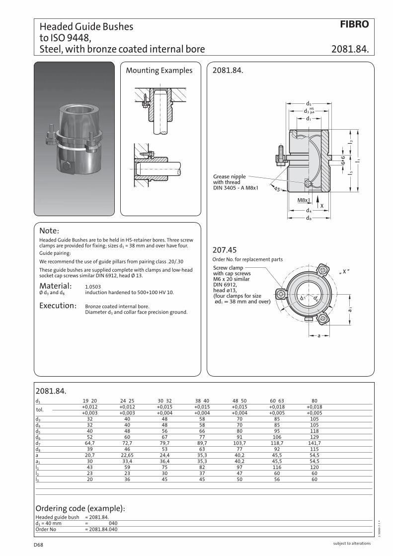
2081.84.d1 19 20 24 25 30 32 38 40 48 50 60 63 80 +0,012 +0,012 +0,015 +0,015 +0,015 +0,018 +0,018 +0,003 +0,003 +0,004 +0,004 +0,004 +0,005 +0,005d3 32 40 48 58 70 85 105d4 32 40 48 58 70 85 105d5 40 48 56 66 80 95 118d6 52 60 67 77 91 106 129d7 64,7 72,7 79,7 89,7 103,7 118,7 141,7d8 39 46 53 63 77 92 115a 20,7 22,65 24,4 35,3 40,2 45,5 54,5a1 30 33,4 36,4 35,3 40,2 45,5 54,5l1 43 59 75 82 97 116 120l2 23 23 30 37 47 60 60l3 20 36 45 45 50 56 60
2·1
00
00
·7·1
°
Note:Headed Guide Bushes are to be held in H5-retainer bores. Three screw clamps are provided for fixing; sizes d1 = 38 mm and over have four.
Guide pairing:
We recommend the use of guide pillars from pairing class .20/.30
These guide bushes are supplied complete with clamps and low-head socket cap screws similar DIN 6912, head Ø 13.
Material: 1.0503 Ø d3 and d8 induction hardened to 500+100 HV 10.
Execution: Bronze coated internal bore. Diameter d3 and collar face precision ground.
Headed Guide Bushes to ISO 9448, Steel, with bronze coated internal bore 2081.84.
Ordering code (example):Headed guide bush = 2081.84.d1 = 40 mm = 2081.81.040Order No = 2081.84.040
Mounting Examples 2081.84.
207.45Order No. for replacement parts
tol.
subject to alterationsD68

2081.85.d1 19 20 24 25 30 32 38 40 48 50 60 63 80 +0,012 +0,012 +0,015 +0,015 +0,015 +0,018 +0,018 +0,003 +0,003 +0,004 +0,004 +0,004 +0,005 +0,005d3 32 40 48 58 70 85 105d4 32 40 48 58 70 85 105d5 40 48 56 66 80 95 118d6 52 60 67 77 91 106 129d7 64,7 72,7 79,7 89,7 103,7 118,7 141,7d8 39 46 53 63 77 92 115a 20,7 22,65 24,4 35,3 40,2 45,5 54,5a1 30 33,4 36,4 35,3 40,2 45,5 54,5l1 35 35 42 52 65 80 80l2 23 23 30 37 47 60 60l3 12 12 12 15 18 20 20
tol.
2·1
00
00
·7·1
°
Note:Headed Guide Bushes are to be held in H5-retainer bores. Three screw clamps are provided for fixing; sizes d1 = 38 mm and over have four.
Guide pairing:
We recommend the use of guide pillars from pairing class .20/.30
These guide bushes are supplied complete with clamps and low-head socket cap screws similar DIN 6912, head Ø 13.
Material: 1.0503 Ø d3 and d8 induction hardened to 500+100 HV 10.
Execution: Bronze coated internal bore. Diameter d3 and collar face precision ground.
Headed Guide Bushes to ISO 9448, 2081.85. Steel, with bronze coated internal bore
Ordering code (example):Headed guide bush = 2081.85.d1 = 40 mm = 2081.85.040Order No = 2081.85.040
Mounting Examples2081.85.
207.45Order No. for replacement parts
subject to alterations D69

2081.31. d1 19 20 24 25 30 32 38 40 48 50 60 63 d3 32 40 48 58 70 85 d4 32 40 48 58 70 85 d5 40 48 56 66 80 95 d6 52 60 67 77 91 106 d7 64,7 72,7 79,7 89,7 103,7 118,7 d8 39 46 53 63 77 92 a 20,7 22,65 24,4 35,3 40,2 45,5 a1 30 33,4 36,4 35,3 40,2 45,5 l1 59 79 93 108 127 150 l2 23 23 30 37 47 60 l3 36 56 63 71 80 90
2·1
00
00
·7·1
°
Note:Headed Guide Bushes are to be held in H5-retainer bores. Three screw clamps are provided for fixing; sizes d1 = 38 mm and over have four.
FIBRO headed guide bushes of sintered ferrite carbonitrided are fully interchangeable with the corresponding sizes of the FIBRO headed ball bearing guide bushes.
Notes on Sliding- and Ball Bearing Guides: page D9.
Guide Pillars: see pages D16, D17, D18, D22 and D35.
These guide bushes are supplied complete with clamps and low-head socket cap screws similar DIN 6912, head Ø 13.
Material:Sintered ferrite of high purity, carbonitrided
Execution:Bore, diameter d3 and collar face precision ground.
Mounting examples 2081.31.
207.45Order No for replacement parts
Headed Guide Bushes to DIN 9831/ISO 9448-6, sintered ferrite, carbonitrided, long-term lubrication 2081.31.
Ordering Code (example):Headed Guide Bush = 2081.31.d1 = 40 mm = 2081.31.040.Tolerance range – yellow = 2081.31.040.10Order No = 2081.31.040.10
* Colour Code Combinations/Clearances – see pages D10 and D 11.
Tolerance range – yellow = .10 green = .20 red = .30
subject to alterationsD70

2081.32. d1 24 25 30 32 38 40 48 50 d3 40 48 58 70 d4 40 48 58 70 d5 48 56 66 80 d6 60 67 77 91 d7 72,7 79,7 89,7 103,7 d8 46 53 63 77 a 22,65 24,4 35,3 40,2 a1 33,4 36,4 35,3 40,2 l1 80 93 110 131 l2 30 37 47 60 l3 50 56 63 71
2·1
00
00
·7·1
°
Note:Headed Guide Bushes are to be held in H5-retainer bores. Three screw clamps are provided for fixing; sizes d1 = 38 mm and over have four.
FIBRO headed guide bushes of sintered ferrite carbonitrided are fully interchangeable with the corresponding sizes of the FIBRO headed ball bearing guide bushes.
Notes on Sliding- and Ball Bearing Guides: page D9.
Guide Pillars: see pages D16, D17, D18, D22 and D35.
These guide bushes are supplied complete with clamps and low-head socket cap screws similar DIN 6912, head Ø 13.
Material:Sintered ferrite of high purity, carbonitrided
Execution:Bore, diameter d3 and collar face precision ground.
Mounting examples2081.32.
207.45Order No for replacement parts
Headed Guide Bushes to DIN 9831/ISO 9448-6, sintered ferrite, 2081.32. carbonitrided, long-term lubrication
* Colour Code Combinations/Clearances – see pages D 10 and D 11.
Ordering Code (example):Headed Guide Bush = 2081.32.d1 = 30 mm = 2081.32.030.Tolerance range – green = 2081.32.030.20Order No = 2081.32.030.20
Tolerance range – yellow = .10 green = .20 red = .30
subject to alterations D71

2081.33. d1 24 25 30 32 38 40 48 50 d3 40 48 58 70 d4 40 48 58 70 d5 48 56 66 80 d6 60 67 77 91 d7 72,7 79,7 89,7 103,7 d8 46 53 63 77 a 22,65 24,4 35,3 40,2 a1 33,4 36,4 35,3 40,2 l1 55 69 79 96 l2 30 37 47 60 l3 25 32 32 36
2·1
00
00
·7·1
°
Note:Headed Guide Bushes are to be held in H5-retainer bores. Three screw clamps are provided for fixing; sizes d1 = 38 mm and over have four.
FIBRO headed guide bushes of sintered ferrite carbonitrided are fully interchangeable with the corresponding sizes of the FIBRO headed ball bearing guide bushes.
Notes on Sliding- and Ball Bearing Guides: page D 9.
Guide Pillars: see pages D16, D17, D18, D22 and D35.
These guide bushes are supplied complete with clamps and low-head socket cap screws similar DIN 6912, head Ø 13.
Material:Sintered ferrite of high purity, carbonitrided
Execution:Bore, diameter d3 and collar face precision ground.
Mounting examples 2081.33.
207.45Order No for replacement parts
Headed Guide Bushes to DIN 9831/ISO 9448-6, sintered ferrite, carbonitrided, long-term lubrication 2081.33.
Ordering Code (example):Headed Guide Bush = 2081.33.d1 = 40 mm = 2081.31.040.Tolerance range – yellow = 2081.31.040.10Order No = 2081.33.040.10
Tolerance range – yellow = .10 green = .20 red = .30
* Colour Code Combinations/Clearances – see pages D10 and D 11.
subject to alterationsD72
2081.34. d1 19 20 24 25 30 32 38 40 48 50 60 63 d3 32 40 48 58 70 85 d4 32 40 48 58 70 85 d5 40 48 56 66 80 95 d6 52 60 67 77 91 106 d7 64,7 72,7 79,7 89,7 103,7 118,7 d8 39 46 53 63 77 92 a 20,7 22,65 24,4 35,3 40,2 45,5 a1 30 33,4 36,4 35,3 40,2 45,5 l1 43 59 75 82 97 116 l2 23 23 30 37 47 60 l3 20 36 45 45 50 56
2·1
00
00
·7·1
°
Note:Headed Guide Bushes are to be held in H5-retainer bores. Three screw clamps are provided for fixing; sizes d1 = 38 mm and over have four.
FIBRO headed guide bushes of sintered ferrite carbonitrided are fully interchangeable with the corresponding sizes of the FIBRO headed ball bearing guide bushes.
Notes on Sliding- and Ball Bearing Guides: page D9.
Guide Pillars: see pages D16, D17, D18, D22 and D35.
These guide bushes are supplied complete with clamps and low-head socket cap screws similar DIN 6912, head Ø 13.
Material:Sintered ferrite of high purity, carbonitrided
Execution:Bore, diameter d3 and collar face precision ground.
Mounting examples2081.34.
207.45Order No for replacement parts
Headed Guide Bushes to DIN 9831/ISO 9448-6, sintered ferrite 2081.34. carbonitrided, long-term lubrication
* Colour Code Combinations/Clearances – see pages D10 and D 11.
Ordering Code (example):Headed Guide Bush = 2081.34.d1 = 30 mm = 030.Tolerance range –green = 20Order No = 2081.34.030.20
Tolerance range – yellow = .10 green = .20 red = .30
subject to alterations D73

2081.35. d1 19 20 24 25 30 32 38 40 48 50 60 63 d3 32 40 48 58 70 85 d4 32 40 48 58 70 85 d5 40 48 56 66 80 95 d6 52 60 67 77 91 106 d7 64,7 72,7 79,7 89,7 103,7 118,7 a 20,7 22,65 24,4 35,3 40,2 45,5 a1 30 33,4 36,4 35,3 40,2 45,5 l1 35 35 42 52 65 80 l2 23 23 30 37 47 60 l3 12 12 12 15 18 20
2·1
00
00
·7·1
°
Note:Headed Guide Bushes are to be held in H5-retainer bores. Three screw clamps are provided for fixing; sizes d1 = 38 mm and over have four.
FIBRO headed guide bushes of sintered ferrite carbonitrided are fully interchangeable with the corresponding sizes of the FIBRO headed ball bearing guide bushes.
Notes on Sliding- and Ball Bearing Guides: page D9.
Guide Pillars: see pages D16, D17, D18, D22 and D35.
These guide bushes are supplied complete with clamps and low-head socket cap screws similar DIN 6912, head Ø 13.
Material:Sintered ferrite of high purity, carbonitrided
Execution:Bore, diameter d3 and collar face precision ground.
Mounting examples 2081.35.
207.45Order No for replacement parts
Headed Guide Bushes to DIN 9831/ISO 9448-6, sintered ferrite, carbonitrided, long-term lubrication 2081.35.
Ordering Code (example):Headed Guide Bush = 2081.33.d1 = 40 mm = 040.Tolerance range – yellow = 10Order No = 2081.33.040.10
* Colour Code Combinations/Clearances – see pages D10 and D 11.
Tolerance range – yellow = .10 green = .20 red = .30
subject to alterationsD74
2081.91.d1 19 20 24 25 30 32 38 40 48 50 60 63 80
d3 32 40 48 58 70 85 105
d4 32 40 48 58 70 85 105
d5 40 48 56 66 80 95 118
d6 52 60 67 77 91 106 129
d7 64,7 72,7 79,7 89,7 103,7 118,7 141,7
d8 39 46 53 63 77 92 115
a 20,7 22,65 24,4 35,3 40,2 45,5 54,5
a1 30 33,4 36,4 35,3 40,2 45,5 54,5
l1 59 79 93 108 127 150 150
l2 23 23 30 37 47 60 60
l3 36 56 63 71 80 90 90
Note:Headed Guide Bushes are to be held in H6-retainer bores. Three screw clamps are provided for fixing; sizes d1 = 38 mm and over have four.
These guide bushes are supplied complete with clamps and low-head socket cap screws similar DIN 6912, head Ø 13.
Material: Steel Ø d3 induction hardened
Execution: Bronze plated internal bore. Diameter d3 and collar face precision ground.
Mounting examples2081.91.
207.45Order No for replacement parts
Ordering code (example):Headed Guide Bushes, bronzeplated = 2081.91.
d1 = 40 mm = 040
Order No = 2081.91.040
ECO-LINE
Headed Guide Bushes, 2081.91. bronzeplated
2·2
06
80
·20
06
·1 °
subject to alterations D75

ECO-LINE
Headed Guide Bushes, bronzeplated 2081.94.
2081.94.d1 19 20 24 25 30 32 38 40 48 50 60 63 80
d3 32 40 48 58 70 85 105
d4 32 40 48 58 70 85 105
d5 40 48 56 66 80 95 118
d6 52 60 67 77 91 106 129
d7 64,7 72,7 79,7 89,7 103,7 118,7 141,7
d8 39 46 53 63 77 92 115
a 20,7 22,65 24,4 35,3 40,2 45,5 54,5
a1 30 33,4 36,4 35,3 40,2 45,5 54,5
l1 43 59 75 82 97 116 120
l2 23 23 30 37 47 60 60
l3 20 36 45 45 50 56 60
Note:Headed Guide Bushes are to be held in H6-retainer bores. Three screw clamps are provided for fixing; sizes d1 = 38 mm and over have four.
These guide bushes are supplied complete with clamps and low-head socket cap screws similar DIN 6912, head Ø 13.
Material: Steel Ø d3 induction hardened
Execution: Bronze plated internal bore. Diameter d3 and collar face precision ground.
Mounting example 2081.94.
207.45 Order No for replacement parts
Ordering Code (example):Headed Guide Bushes, bronzeplated = 2081.94.
d1 = 63 mm = 063
Order No = 2081.94.063
subject to alterationsD76

2081.95.d1 19 20 24 25 30 32 38 40 48 50 60 63 80
d3 32 40 48 58 70 85 105
d4 32 40 48 58 70 85 105
d5 40 48 56 66 80 95 118
d6 52 60 67 77 91 106 129
d7 64,7 72,7 79,7 89,7 103,7 118,7 141,7
d8 39 46 53 63 77 92 115
a 20,7 22,65 24,4 35,3 40,2 45,5 54,5
a1 30 33,4 36,4 35,3 40,2 45,5 54,5
l1 35 35 42 52 65 80 80
l2 23 23 30 37 47 60 60
l3 12 12 12 15 18 20 20
Note:Headed Guide Bushes are to be held in H6-retainer bores. Three screw clamps are provided for fixing; sizes d1 = 38 mm and over have four.
These guide bushes are supplied complete with clamps and low-head socket cap screws similar DIN 6912, head Ø 13.
Material: Steel Ø d3 induction hardened
Execution: Bronze plated internal bore. Diameter d3 and collar face precision ground.
Mounting example2081.95.
207.45Order No for replacement parts
Ordering Code (example):Headed Guide Bushes, bronzeplated = 2081.95.
d1 = 63 mm = 063
Order No = 2081.95.063
ECO-LINE
Headed Guide Bushes, 2081.95. bronzeplated
2·2
06
80
·20
06
·1 °
subject to alterations D77
ECO-LINE
Headed Guide Bushes, Bronze with solid lubrication rings 2081.71.
2081.71.d1 19 20 24 25 30 32 38 40 48 50 60 63 80
d3 32 40 48 58 70 85 105
d4 32 40 48 58 70 85 105
d5 40 48 56 66 80 95 118
d6 52 60 67 77 91 106 129
d7 64,7 72,7 79,7 89,7 103,7 118,7 141,7
d8 39 46 53 63 77 92 115
a 20,7 22,65 24,4 35,3 40,2 45,5 54,5
a1 30 33,4 36,4 35,3 40,2 45,5 54,5
l1 59 79 93 108 127 150 150
l2 23 23 30 37 47 60 60
l3 36 56 63 71 80 90 90
Note:Headed Guide Bushes are to be held in H6-retainer bores. Three screw clamps are provided for fixing; sizes d1 = 38 mm and over have four.
These guide bushes are supplied complete with clamps and low-head socket cap screws similar DIN 6912, head Ø 13.
Material: Bronze
Execution: Contact surfaces with solid lubricant rings. Diameter d3 and collar face precision ground.
Mounting Example 2081.71.
207.45Order No for replacement parts
Ordering Code (example):Headed Guide Bushes, Bronze = 2081.71.d1 = 40 mm = 040Order No = 2081.71.040
subject to alterationsD78

ECO-LINE
Headed Guide Bushes, 2081.74. Bronze with solid lubrication rings
2081.74.d1 19 20 24 25 30 32 38 40 48 50 60 63 80
d3 32 40 48 58 70 85 105
d4 32 40 48 58 70 85 105
d5 40 48 56 66 80 95 118
d6 52 60 67 77 91 106 129
d7 64,7 72,7 79,7 89,7 103,7 118,7 141,7
d8 39 46 53 63 77 92 115
a 20,7 22,65 24,4 35,3 40,2 45,5 54,5
a1 30 33,4 36,4 35,3 40,2 45,5 54,5
l1 43 59 75 82 97 116 120
l2 23 23 30 37 47 60 60
l3 20 36 45 45 50 56 60
Note:Headed Guide Bushes are to be held in H6-retainer bores. Three screw clamps are provided for fixing; sizes d1 = 38 mm and over have four.
These guide bushes are supplied complete with clamps and low-head socket cap screws similar DIN 6912, head Ø 13.
Material: Bronze
Execution: Contact surfaces with solid lubricant rings. Diameter d3 and collar face precision ground.
Mounting Example2081.74.
207.45Order No for replacement parts
Ordering Code (example):Headed Guide Bushes, Bronze = 2081.74.d1 = 25 mm = 025Order No = 2081.74.025
subject to alterations D79

ECO-LINE
Headed Guide Bushes, Bronze with solid lubrication rings 2081.75.
2081.75.d1 19 20 24 25 30 32 38 40 48 50 60 63 80
d3 32 40 48 58 70 85 105
d4 32 40 48 58 70 85 105
d5 40 48 56 66 80 95 118
d6 52 60 67 77 91 106 129
d7 64,7 72,7 79,7 89,7 103,7 118,7 141,7
d8 39 46 53 63 77 92 115
a 20,7 22,65 24,4 35,3 40,2 45,5 54,5
a1 30 33,4 36,4 35,3 40,2 45,5 54,5
l1 35 35 42 52 65 80 80
l2 23 23 30 37 47 60 60
l3 12 12 12 15 18 20 20
Note:Headed Guide Bushes are to be held in H6-retainer bores. Three screw clamps are provided for fixing; sizes d1 = 38 mm and over have four.
These guide bushes are supplied complete with clamps and low-head socket cap screws similar DIN 6912, head Ø 13.
Material: Bronze
Execution: Contact surfaces with solid lubricant rings. Diameter d3 and collar face precision ground.
Mounting Example 2081.75.
207.45Order No for replacement parts
Ordering Code (example):Headed Guide Bushes, Bronze = 2081.75.d1 = 63 mm = 063Order No = 2081.75.063
subject to alterationsD80

Headed Guide Bushes for Ball Bearings 2081.44. DIN 9831/ISO 9448-7 206.71. Ball Cages
2081.44.d1 19 20 24 25 30 32 38 40 48 50 60 63 80d2 25 26 30 31 38 40 46 48 56 58 68 71 92d3 32 40 48 58 70 85 105d4 32 40 48 58 70 85 105d5 40 48 56 66 80 95 118d6 52 60 67 77 91 106 129d7 64,7 72,7 79,7 89,7 103,7 118,7 141,7d8 39 46 53 63 77 92 115a 20,7 22,65 24,4 35,3 40,2 45,5 54,5a1 30 33,4 36,4 35,3 40,2 45,5 54,5l1 59 79 93 108 127 150 150l2 23 23 30 37 47 60 60l3 36 56 63 71 80 90 90
206.71. (preferred length)d1 19 20 24 25 30 32 38 40 48 50 60 63 80l 71 95 120 120 140 160 160 l = Nominal ordering lengthl4 72 96 120 120 140 160 161 l4 = Manufacturing length
Execution:Bearing surfaces honed. Outside diameter fine-ground.
Note:Headed Guide Bushes are to be held in H5-retainer bores.
Three screw clamps are provided for fixing; sizes Ø d1 = 38 mm and over have four.
FIBRO headed guide bushes for ball bearings are fully interchangeable with the corresponding sizes of the FIBRO headed guide bushes of sintered ferrite.
Notes on Sliding and Ball Bearing Guides see page D9.
Guide Pillars see pages D16, D17, D18, D22 and D35.
Ball guide capacity calculations see pages D56 and D57.
Material:Bush: tool steel, Hardness: 62 ± 2HRC
Ball Cage: brass
Balls: hardened steel DIN 5401
Ordering Code (example):Headed Guide Bush = 2081.44.d1 = 40 mm = 2081.44.040.Tolerance range – red = 2081.44.040.30Order No = 2081.44.040.30
2081.44.
207.45Order No for replacement parts
Ball Cages = 206.71.d1 = 40 mm = 206.71.040.l = 120 mm = 206.71.040.120Order No = 206.71.040.120
Tolerance range – yellow = .10 green = .20 red = .30
* Preloading see Colour Code Combinations – pages D10 and D11.
subject to alterations D81

Headed Guide Bushes for Ball Bearings DIN 9831/ISO 9448-7 2081.45. Ball Cages 206.71.
2081.45.d1 24 25 30 32 38 40 48 50d2 30 31 38 40 46 48 56 58d3 40 48 58 70d4 40 48 58 70d5 48 56 66 80d6 60 67 77 91d7 72,7 79,7 89,7 103,7d8 46 53 63 77a 22,65 24,4 35,3 40,2a1 33,4 36,4 35,3 40,2l1 80 93 110 131l2 30 37 47 60l3 50 56 63 71
206.71. (preferred length)d1 24 25 30 32 38 40 48 50l 95 120 140 160 l = Nominal ordering lengthl4 96 120 140 160 l4 = Manufacturing length
Execution:Bearing surfaces honed. Outside diameter fine-ground.
Note:Headed Guide Bushes are to be held in H5-retainer bores.
Three screw clamps are provided for fixing; sizes Ø d1 = 38 mm and over have four.
FIBRO headed guide bushes for ball bearings are fully interchangeable with the corresponding sizes of the FIBRO headed guide bushes of sintered ferrite.
Notes on Sliding and Ball Bearing Guides see page D9.
Guide Pillars see pages D16, D17, D18, D22 and D35.
Ball guide capacity calculations see pages D56 and D57.
Material:Bush: tool steel, Hardness: 62 ± 2HRC Ball Cage: brass Balls: hardened steel DIN 5401
Ordering Code (example):Headed Guide Bush = 2081.45.d1 = 40 mm = 2081.44.040.Tolerance range- red = 2081.44.040.30Order No = 2081.45.040.30
2081.45.
207.45Order No for replacement parts
Ball Cages = 206.71.d1 = 40 mm = 206.71.040.l = 120 mm = 206.71.040.120Order No = 206.71.040.120
Tolerance yellow = .10range – green = .20 red = .30
* Preloading see Colour Code Combinations – pages D10 and D11.
subject to alterationsD82

Headed Guide Bushes for Ball Bearings 2081.46. DIN 9831/ISO 9448-7 206.71. Ball Cages
2081.46.d1 19 20 24 25 30 32 38 40 48 50 60 63 80d2 25 26 30 31 38 40 46 48 56 58 68 71 92d3 32 40 48 58 70 85 105d4 32 40 48 58 70 85 105d5 40 48 56 66 80 95 118d6 52 60 67 77 91 106 129d7 64,7 72,7 79,7 89,7 103,7 118,7 141,7d8 39 46 53 63 77 92 115a 20,7 22,65 24,4 35,3 40,2 45,5 54,5a1 30 33,4 36,4 35,3 40,2 45,5 54,5l1 43 59 75 82 97 116 120l2 23 23 30 37 47 60 60l3 20 36 45 45 50 56 60
206.71. (preferred length)d1 19 20 24 25 30 32 38 40 48 50 60 63 80l 56 71 95 105 120 140 140 l = Nominal ordering lengthl4 56 72 95 105 120 140 140 l4 = Manufacturing length
Execution:Bearing surfaces honed. Outside diameter fine-ground.
Note: Headed Guide Bushes are to be held in H5-retainer bores.
Three screw clamps are provided for fixing; sizes Ø d1 = 38 mm and over have four.
FIBRO headed guide bushes for ball bearings are fully interchangeable with the corresponding sizes of the FIBRO headed guide bushes of sintered ferrite.
Notes on Sliding and Ball Bearing Guides see page D9.
Guide Pillars see pages D16, D17, D18, D22 and D35.
Ball guide capacity calculations see pages D56 and D57.
Material:Bush: tool steel, Hardness: 62 ± 2HRC Ball Cage: brass Balls: hardened steel DIN 5401
Ordering Code (example):Headed Guide Bush = 2081.46.d1 = 40 mm = 2081.44.040.Tolerance range-red = 2081.44.040.30Order No = 2081.46.040.30
2081.46.
207.45Order No for replacement parts
Ball Cages = 206.71.d1 = 40 mm = 206.71.040.l = 120 mm = 206.71.040.120Order No = 206.71.040.120
Tolerance yellow = .10range – green = .20 red = .30
* Preloading see Colour Code Combinations – pages D10 and D11.
subject to alterations D83

Headed Guide Bushes for Ball Bearings DIN 9831/ISO 9448-7 2081.47. Ball Cages 206.71.
2081.47.d1 19 20 24 25 30 32 38 40 48 50 60 63 80d2 25 26 30 31 38 40 46 48 56 58 68 71 92d3 32 40 48 58 70 85 105d4 32 40 48 58 70 85 105d5 40 48 56 66 80 95 118d6 52 60 67 77 91 106 129d7 64,7 72,7 79,7 89,7 103,7 118,7 141,7d8 39 46 53 63 77 92 115a 20,7 22,65 24,4 35,3 40,2 45,5 54,5a1 30 33,4 36,4 35,3 40,2 45,5 54,5l1 35 35 42 52 65 80 80l2 23 23 30 37 47 60 60l3 12 12 12 15 18 20 20
206.71. (preferred length)d1 19 20 24 25 30 32 38 40 48 50 60 63 80l 45 45 56 63 80 95 120 l = Nominal ordering lengthl4 44 44 55 65 80 95 119 l4 = Manufacturing length
Execution:Bearing surfaces honed. Outside diameter fine-ground.
Note:Headed Guide Bushes are to be held in H5-retainer bores.
Three screw clamps are provided for fixing; sizes Ø d1 = 38 mm and over have four.
FIBRO headed guide bushes for ball bearings are fully interchangeable with the corresponding sizes of the FIBRO headed guide bushes of sintered ferrite.
Notes on Sliding and Ball Bearing Guides see page D 9.
Guide Pillars see pages D16, D17, D18, D22 and D35.
Ball guide capacity calculations see pages D56 and D57.
Material:Bush: tool steel Hardness: 62 ± 2HRC
Ball Cage: brass
Balls: hardened steel DIN 5401
Ordering Code (example):Headed Guide Bush = 2081.47.d1 = 40 mm = 2081.44.040.Tolerance range- red = 2081.44.040.30Order No = 2081.47.040.30
2081.47.
207.45Order No for replacement parts
Ball Cages = 206.71.d1 = 40 mm = 206.71.040.l = 120 mm = 206.71.040.120Order No = 206.71.040.120
Tolerance yellow = .10range – green = .20 red = .30
* Preloading see Colour Code Combinations – pages D10 and D11. .
subject to alterationsD84

Headed Guide Bushes for Ball Bearings 2081.49. DIN 9831/ISO 9448-7 206.71. Ball Cages
2081.49.d1 24 25 30 32 38 40 48 50d2 30 31 38 40 46 48 56 58d3 40 48 58 70d4 40 48 58 70d5 48 56 66 80d6 60 67 77 91d7 72,7 79,7 89,7 103,7d8 46 53 63 77a 22,65 24,4 35,3 40,2a1 33,4 36,4 35,3 40,2l1 55 69 79 96l2 30 37 47 60l3 25 32 32 36
206.71. (preferred length)d1 24 25 30 32 38 40 48 50l 71 80 95 120 l = Nominal ordering lengthl4 72 80 95 120 l4 = Manufacturing length
Execution:Bearing surfaces honed. Outside diameter fine-ground.
Note:Headed Guide Bushes are to be held in H5-retainer bores.
Three screw clamps are provided for fixing; sizes Ø d1 = 38 mm and over have four.
FIBRO headed guide bushes for ball bearings are fully interchangeable with the corresponding sizes of the FIBRO headed guide bushes of sintered ferrite.
Notes on Sliding and Ball Bearing Guides see page D 9.
Guide Pillars see pages D16, D17, D18, D22 and D35.
Ball guide capacity calculations see pages D56 and D57.
Material:Bush: tool steel Hardness: 62 ± 2HRC
Ball Cage: brass
Balls: hardened steel DIN 5401
Ordering Code(example):Headed Guide Bush = 2081.49.d1 = 40 mm = 2081.44.040.Tolerance range- red = 2081.44.040.30Order No = 2081.49.040.30
2081.49.
207.45Order No for replacement parts
Ball Cages = 206.71.d1 = 40 mm = 206.71.040.l = 120 mm = 206.71.040.120Order No = 206.71.040.120
Tolerance yellow = .10range – green = .20 red = .30
* Preloading see Colour Code Combinations – pages D10 and D11.
subject to alterations D85
2091.31. d1 19 20 24 25 30 32 38 40 48 50 60 63 80 d3 32 40 48 58 70 85 105 d4 50 63 72 85 104 120 148 d5* 40 50 58 70 86 100 125 d6 4,5 5,5 5,5 6,6 9 9 11 k 18 23 28 33 38 46 56 l1 52 62 72 77 102 102 125 l2 37 37 47 47 60 60 75 l3 15 25 25 30 42 42 50 t 4,6 5,7 5,7 6,8 9 9 11
2·1
00
00
·7·1
°
Material: Sintered ferrite of high purity, carbonitrided.
Execution: Bearing surfaces and outside diameter fine-ground.
Note: Register bore H5. The guide bush is fixed by means of 3 screws to DIN EN ISO 4762. The screws are not contained in the scope of delivery.
FIBRO flanged guide bushes of sintered ferrite carbonitrided are fully interchangeable with the corresponding sizes of the FIBRO flanged guide bushes for ball bearings.
Mounting Examples 2091.31.
Flanged Guide Bushes, sintered ferrite, DIN 9831/ISO9448-4, carbonitrided long-term lubrication 2091.31.
Ordering Code (example):Flanged Guide Bush = 2091.31.d1 = 40 mm = 2091.31.040.Tolerance range – red = 2091.31.040.30Order No = 2091.31.040.30
Tolerance yellow = .10range – green = .20 red = .30
* Colour Code Combinations/Clearances – see pages D10 and D 11.
Notes on Sliding- and Ball Bearing Guides: see page D9.
Guide Pillars: see pages D16, D17, D18, D22 and D35.
subject to alterationsD86

2091.32. d1 15* 16* 19 20 24 25 30 32 38 40 48 50 60 63 d3 28 32 40 48 58 70 85 d4 45 50 63 72 85 104 120 d5* 35 40 50 58 70 86 100 d6 4,5 4,5 5,5 5,5 6,6 9 9 k 15 18 23 28 33 38 46 l1 36 45 55 62 67 89 89 l2 30 30 30 37 37 47 47 l3 6 15 25 25 30 42 42 t 3,4 4,6 5,7 5,7 6,8 9 9 * use Shallow Head Cap Screws DIN 6912!
2·1
00
00
·7·1
°
Material:Sintered ferrite of high purity, carbonitrided
Execution:Bearing surfaces and outside diameter fine-ground.
Note:Register bore H5. The guide bush is fixed by means of 3 screws to DIN EN ISO 4762, except for dias. 15 + 16, which require screws to DIN 6912. The screws are not contained in the scope of delivery.
FIBRO flanged guide bushes of sintered ferrite carbonitrided are fully interchangeable with the corresponding sizes of the FIBRO flanged guide bushes for ball bearings.
Mounting Examples2091.32.
Flanged Guide Bushes, sintered ferrite, DIN 9831/ISO 9448-4, 2091.32. carbonitrided, long-term lubrication
* Colour Code Combinations/Clearances – see pages D10 and D11.
Ordering Code (example):Flanged Guide Bush = 2091.32.d1 = 38 mm = 038.Tolerance range – red = 30Order No = 2091.32.038.30
Tolerance yellow = .10range – green = .20 red = .30
Notes on Sliding- and Ball Bearing Guides: see page D9.
Guide Pillars: see pages D16, D17, D18, D22 and D35.
subject to alterations D87

2091.34. d1 15* 16* 19 20 24 25 30 32 38 40 48 50 d3 28 32 40 48 58 70 d4 45 50 63 72 85 104 d5* 35 40 50 58 70 86 d6 4,5 4,5 5,5 5,5 6,6 9 k 15 18 23 28 33 38 l1 29 38 38 45 55 62 l2 23 23 23 30 30 37 l3 6 15 15 15 25 25 t 3,4 4,6 5,7 5,7 6,8 9 * use Shallow Head Cap Screws DIN 6912!
2·1
00
00
·7·1
°
Material: Sintered ferrite of high purity, carbonitrided.
Execution: Bearing surfaces and outside diameter fine-ground.
Note: Register bore H5. The guide bush is fixed by means of 3 screws to DIN EN ISO 4762, except for dias. 15 + 16, which require screws to DIN 6912. The screws are not contained in the scope of delivery.
FIBRO flanged guide bushes of sintered ferrite carbonitrided are fully interchangeable with the corresponding sizes of the FIBRO flanged guide bushes for ball bearings.
Mounting Examples 2091.34.
Flanged Guide Bushes, sintered ferrite, DIN 9831/ISO 9448-4, carbonitrided, long-term lubrication 2091.34.
Ordering Code (example):Flanged Guide Bush = 2091.34.d1 = 40 mm = 040.Tolerance range – red = 30Order No = 2091.34.040.30
Tolerance yellow = .10range – green = .20 red = .30
* Colour Code Combinations/Clearances – see pages D10 and D 11.
Notes on Sliding- and Ball Bearing Guides: see page D9.
Guide Pillars: see pages D16, D17, D18, D22 and D35.
subject to alterationsD88
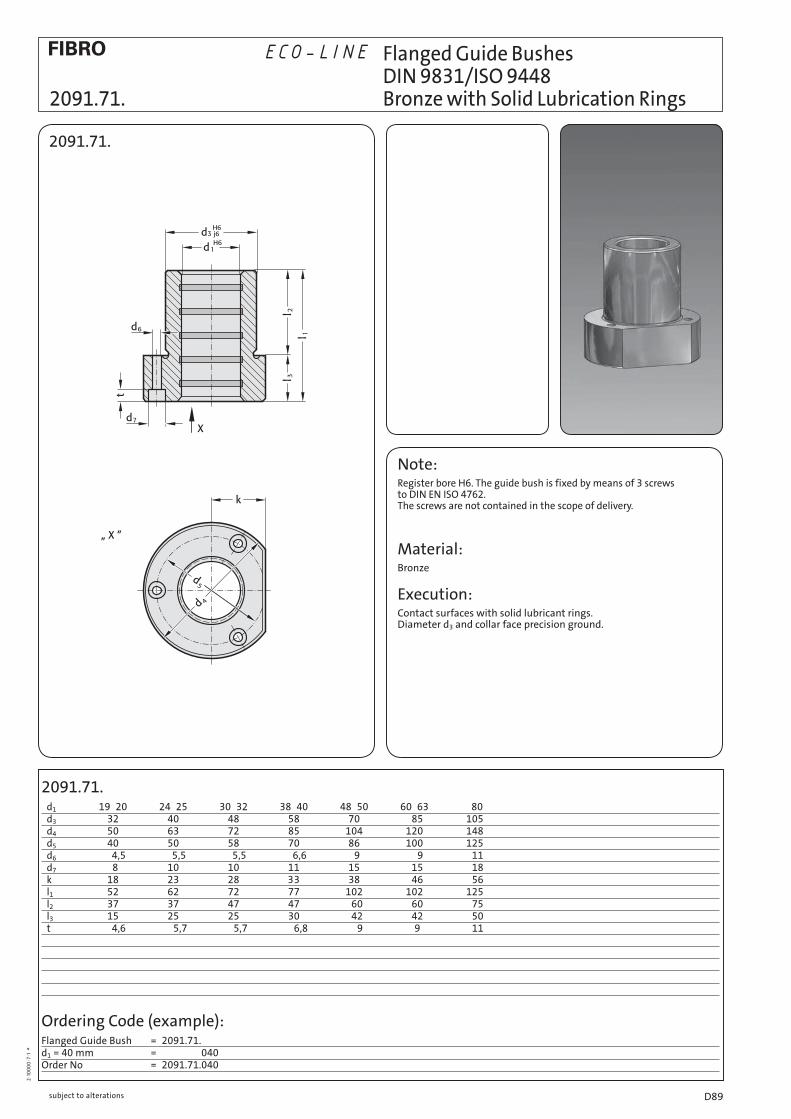
2091.71. d1 19 20 24 25 30 32 38 40 48 50 60 63 80 d3 32 40 48 58 70 085 105 d4 50 63 72 85 104 120 148 d5 40 50 58 70 86 100 125 d6 004,5 005,5 005,5 006,6 09 009 011 d7 8 10 10 11 15 015 018 k 18 23 28 33 38 046 056 l1 52 62 72 77 102 102 125 l2 37 37 47 47 060 060 075 l3 15 25 25 30 042 042 050 t 004,6 00 5,7 00 5,7 00 6,8 009 09 011
2·1
00
00
·7·1
°
Note:Register bore H6. The guide bush is fixed by means of 3 screws to DIN EN ISO 4762. The screws are not contained in the scope of delivery.
Material: Bronze
Execution: Contact surfaces with solid lubricant rings.Diameter d3 and collar face precision ground.
2091.71.
Flanged Guide Bushes DIN 9831/ISO 9448 2091.71. Bronze with Solid Lubrication Rings
Ordering Code (example):Flanged Guide Bush = 2091.71.d1 = 40 mm = 040Order No = 2091.71.040
ECO-LINE
subject to alterations D89

2091.72. d1 15* 16* 19 20 24 25 30 32 38 40 48 50 60 63 d3 28 32 40 48 58 70 085 d4 45 50 63 72 85 104 120 d5 35 40 50 58 70 86 100 d6 004,5 004,5 005,5 005,5 006,6 09 009 d7 6 8 10 10 11 15 015 k 15 18 23 28 33 38 046 l1 36 45 55 62 67 89 089 l2 30 30 30 37 37 47 047 l3 06 15 25 25 30 42 042 t 00 3,4 00 4,6 00 5,7 00 5,7 00 6,8 09 009 * use Shallow Head Cap Screws DIN 6912!
2·1
00
00
·7·1
°
Note: Register bore H6. The guide bush is fixed by means of 3 screws to DIN EN ISO 4762, except for dias. 15 + 16, which require screws to DIN 6912. The screws are not contained in the scope of delivery.
Material:Bronze.
Execution: Contact surfaces with solid lubricant rings.Diameter d3 and collar face precision ground.
2091.72.
Flanged Guide Bushes DIN 9831/ISO 9448-4 Bronze with Solid Lubrication Rings 2091.72.
Ordering Code (example):Flanged Guide Bush = 2091.72.d1 = 40 mm = 040Order No = 2091.72.040
ECO-LINE
subject to alterationsD90

2091.74. d1 15* 16* 19 20 24 25 30 32 38 40 48 50 d3 28 32 40 48 58 70 d4 45 50 63 72 85 104 d5 35 40 50 58 70 86 d6 004,5 004,5 005,5 005,5 006,6 09 d7 6 8 10 10 11 15 k 15 18 23 28 33 38 l1 29 38 38 45 55 62 l2 23 23 23 30 30 37 l3 06 15 15 15 25 25 t 003,4 004,6 005,7 005,7 006,8 09 * use Shallow Head Cap Screws DIN 6912!
2·1
00
00
·7·1
°
Note: Register bore H6. The guide bush is fixed by means of 3 screws to DIN EN ISO 4762, except for dias. 15 + 16, which require screws to DIN 6912. The screws are not contained in the scope of delivery.
Material:Bronze.
Execution: Contact surfaces with solid lubricant rings.Diameter d3 and collar face precision ground.
2091.74.
Flanged Guide Bushes DIN 9831/ISO 9448-4 2091.74. Bronze with Solid Lubrication Rings
Ordering Code (example):Flanged Guide Bush = 2091.74.d1 = 40 mm = 040Order No = 2091.74.040
ECO-LINE
subject to alterations D91
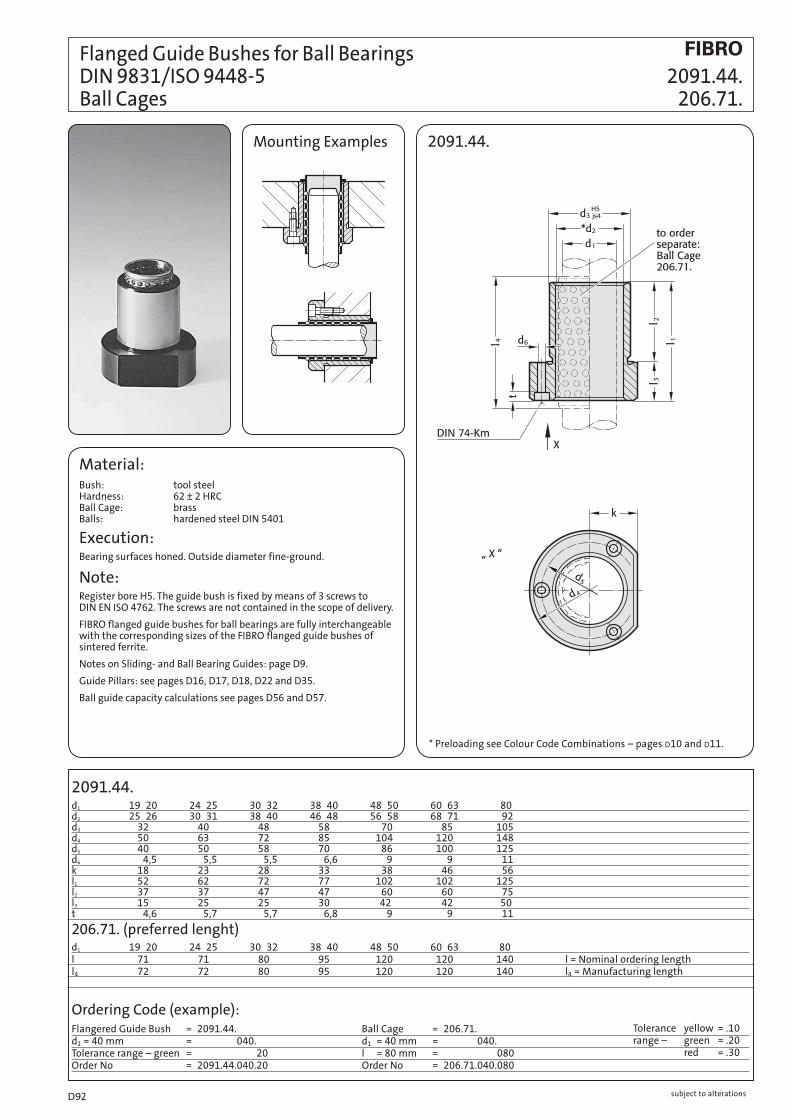
Flanged Guide Bushes for Ball Bearings DIN 9831/ISO 9448-5 2091.44. Ball Cages 206.71.
2091.44.d1 19 20 24 25 30 32 38 40 48 50 60 63 80d2 25 26 30 31 38 40 46 48 56 58 68 71 92d3 32 40 48 58 70 85 105d4 50 63 72 85 104 120 148d5 40 50 58 70 86 100 125d6 4,5 5,5 5,5 6,6 9 9 11k 18 23 28 33 38 46 56l1 52 62 72 77 102 102 125l2 37 37 47 47 60 60 75l3 15 25 25 30 42 42 50t 4,6 5,7 5,7 6,8 9 9 11
206.71. (preferred lenght)d1 19 20 24 25 30 32 38 40 48 50 60 63 80l 71 71 80 95 120 120 140 l = Nominal ordering lengthl4 72 72 80 95 120 120 140 l4 = Manufacturing length
Material:Bush: tool steel Hardness: 62 ± 2 HRC Ball Cage: brass Balls: hardened steel DIN 5401
Execution:Bearing surfaces honed. Outside diameter fine-ground.
Note:Register bore H5. The guide bush is fixed by means of 3 screws to DIN EN ISO 4762. The screws are not contained in the scope of delivery.
FIBRO flanged guide bushes for ball bearings are fully interchangeable with the corresponding sizes of the FIBRO flanged guide bushes of sintered ferrite.
Notes on Sliding- and Ball Bearing Guides: page D9.
Guide Pillars: see pages D16, D17, D18, D22 and D35.
Ball guide capacity calculations see pages D56 and D57.
Ordering Code (example):Flangered Guide Bush = 2091.44.d1 = 40 mm = 2091.44.040.Tolerance range – green = 2091.44.040.20Order No = 2091.44.040.20
2091.44.
Ball Cage = 206.71.d1 = 40 mm = 206.71.040.l = 80 mm = 206.71.040.080Order No = 206.71.040.080
Tolerance yellow = .10range – green = .20 red = .30
Mounting Examples
* Preloading see Colour Code Combinations – pages D 10 and D 11.
subject to alterationsD92

Flanged Guide Bushes for Ball Bearings 2091.45. DIN 9831/ISO 9448-5 206.71. Ball Cages
2091.45.d1 15* 16* 19 20 24 25 30 32 38 40 48 50 60 63d2 21 22 25 26 30 31 38 40 46 48 56 58 68 71d3 28 32 40 48 58 70 85d4 45 50 63 72 85 104 120d5 35 40 50 58 70 86 100d6 4,5 4,5 5,5 5,5 6,6 9 9k 15 18 23 28 33 38 46l1 36 45 55 62 67 89 89l2 30 30 30 37 37 47 47l3 6 15 25 25 30 42 42t 3,4 4,6 5,7 5,7 6,8 9 9
206.71. (preferred lenght)d1 15* 16* 19 20 24 25 30 32 38 40 48 50 60 63 * use Shallow Head Cap Screws DIN 6912!l 45 56 71 71 80 95 95 l = Nominal ordering lengthl4 44 56 72 70 80 95 95 l4 = Manufacturing length
Material:Bush: tool steel Hardness: 62 ± 2 HRC Ball Cage: brass Balls: hardened steel DIN 5401
Execution:Bearing surfaces honed. Outside diameter fine-ground.
Note:Register bore H5. The guide bush is fixed by means of 3 screws to DIN EN ISO 4762, except for dias. 15 + 16, which require screws to DIN 6912. The screws are not contained in the scope of delivery.
FIBRO flanged guide bushes for ball bearings are fully interchangeable with the corresponding sizes of the FIBRO flanged guide bushes of sintered ferrite.
Notes on Sliding- and Ball Bearing Guides: page D9.
Guide Pillars: see pages D16, D17, D18, D22 and D35.
Ball guide capacity calculations see pages D56 and D57.
Ordering Code (example):FlangeredGuide Bush = 2091.45.d1 = 40 mm = 2081.44.040.Tolerance range – red = 2081.44.040.30Order No = 2091.45.040.30
2091.45.
Ball Cage = 206.71.d1 = 40 mm = 206.71.040.l = 120 mm = 206.71.040.120Order No = 206.71.040.120
Mounting Examples
* Preloading see Colour Code Combinations – pages D 10 and D 11.
Tolerance yellow = .10range – green = .20 red = .30
subject to alterations D93

Flanged Guide Bushes for Ball Bearings DIN 9831/ISO 9448-5 2091.46. Ball Cages 206.71.
2091.46.d1 12 15* 16* 19 20 24 25 30 32 38 40 48 50d2 16 21 22 25 26 30 31 38 40 46 48 56 58d3 26 28 32 40 48 58 70d4 43 45 50 63 72 85 104d5 33 35 40 50 58 70 86d6 4,5 4,5 4,5 5,5 5,5 6,6 9k 13 15 18 23 28 33 38l1 25 29 38 38 45 55 62l2 16 23 23 23 30 30 37l3 9 6 15 15 15 25 25t 4,6 3,4 4,6 5,7 5,7 6,8 9
206.71. (preferred lenght)d1 12 15* 16* 19 20 24 25 30 32 38 40 48 50 * use Shallow Head Cap Screws DIN 6912!l 40 45 45 45 56 63 80 l = Nominal ordering lengthl4 39 44 44 44 55 65 80 l4 = Manufacturing length
Material:Bush: tool steel Hardness: 62 ± 2 HRC Ball Cage: brass Balls: hardened steel DIN 5401
Execution:Bearing surfaces honed. Outside diameter fine-ground.
Note:Register bore H5. The guide bush is fixed by means of 3 screws to DIN EN ISO 4762, except for dias. 15 + 16, which require screws to DIN 6912. The screws are not contained in the scope of delivery.
FIBRO flanged guide bushes for ball bearings are fully interchangeable with the corresponding sizes of the FIBRO flanged guide bushes of sintered ferrite.
Notes on Sliding- and Ball Bearing Guides: page D9.
Guide Pillars: see pages D16, D17, D18, D22 and D35.
Ball guide capacity calculations see pages D56 and D57.
Ordering Code (example):Flangered Guide Bush = 2091.46.d1 = 40 mm = 2081.44.040.Tolerance range – green = 2081.44.040.20Order No = 2091.46.040.20
2091.46.
Ball Cage = 206.71.d1 = 40 mm = 206.71.040.l = 120 mm = 206.71.040.120Order No = 206.71.040.120
Mounting Examples
Tolerance yellow = .10range – green = .20 red = .30
* Preloading see Colour Code Combinations – pages D 10 and D 11.
subject to alterationsD94

210.31.
d1 19 20 25 32 40 50d3 32 40 50 63 80d4 32 40 50 63 80d5 36 45 56 70 90d6 49 57 67 81 101d7 61,7 69,7 79,7 93,7 113,7d8 35 43,5 53 67 87a 19,9 21,9 24,4 36 43a1 28,6 32,1 36,4 36 43l1 66 70 83 98 120l2 30 30 38 48 61l3 36 40 45 50 59
Material: Sintered ferrite of high purity, carbonitrided.
Execution: Bearing surfaces and outside diameter fine-ground.
Note: Headed Guide Bushes are to be held in H6-retainer bores. Three screw clamps are provided for fixing; sizes d1 = 40 mm and over have four.
FIBRO headed guide bushes of sintered ferrite carbonitrided are fully interchangeable with the corresponding sizes of the FIBRO guide bushes for ball bearings.
Notes on Sliding- and Ball Bearing Guides: page D9.
Guide Pillars: see pages D16, D17, D18, D22 and D35.
These guide bushes are supplied complete with clamps and low-head socket cap screws similar DIN 6912, head Ø13.
Mounting Examples210.31.
Headed Guide Bushes, sintered ferrite, similar AFNOR carbonitrided 210.31. long-term lubrication
Ordering Code (example):Headed Guide Bush = 210.31.d1 = 40 mm = 040.Toerance range-green = 20Order No = 210.31.040.20
207.45Order No for repeat-order.
Tolerance yellow = .10range – green = .20 red = .30
* Colour Code Combinations/Clearances – see pages D10 and D11.
subject to alterations D95

210.34.
d1 19 20 25 32 40 50
d3 32 40 50 63 80
d4 32 40 50 63 80
d5 36 45 56 70 90
d6 49 57 67 81 101
d7 61,7 69,7 79,7 93,7 113,7
d8 35 43,5 53 67 87
a 19,9 21,9 24,4 36 43
a1 28,6 32,1 36,4 36 43
l1 42 50 63 76 96
l2 30 38 48 61 78
l3 12 12 15 15 18
Material:
Sintered ferrite of high purity, carbonitrided.
Execution: Bearing surfaces and outside diameter fine-ground.
Note: Headed Guide Bushes are to be held in H6-retainer bores. Three screw clamps are provided for fixing; sizes d1 = 40 mm and over have four.
FIBRO headed guide bushes of sintered ferrite carbonitrided are fully interchangeable with the corresponding sizes of the FIBRO guide bushes for ball bearings.
Notes on Sliding- and Ball Bearing Guides: page D9.
Guide Pillars: see pages D16, D17, D18, D22 and D35.
These guide bushes are supplied complete with clamps and low-head socket cap screws similar DIN 6912, head Ø13.
Mounting Examples 210.34.
Headed Guide Bushes, sintered ferrite, similar AFNOR carbonitrided long-term lubrication 210.34.
Ordering Code (example):Headed Guide Bush = 210.34.d1 = 40 mm = 040.Tolerance range – red = 30Order No = 210.34.040.30
207.45Order No for repeat-order.
Tolerance yellow = .10range – green = .20 red = .30
* Colour Code Combinations/Clearances – see pages D 10 and D 11.
subject to alterationsD96

210.35.
d1 19 20 25 32 40 50d3 32 40 50 63 80d4 32 40 50 63 80d5 36 45 56 70 90d6 49 57 67 81 101d7 61,7 69,7 79,7 93,7 113,7a 19,9 21,9 24,4 36 43a1 28,6 32,1 36,4 36 43l1 28 32 37 44 44l2 16 20 25 32 32l3 12 12 12 12 12
2·9
26
9·9
·4 °
Material: Sintered ferrite of high purity, carbonitrided.
Execution: Bearing surfaces and outside diameter fine-ground.
Note: Headed Guide Bushes are to be held in H6-retainer bores. Three screw clamps are provided for fixing; sizes d1 = 40 mm and over have four.
FIBRO headed guide bushes of sintered ferrite carbonitrided are fully interchangeable with the corresponding sizes of the FIBRO guide bushes for ball bearings.
Notes on Sliding- and Ball Bearing Guides: page D9.
Guide Pillars: see pages D16, D17, D18, D22 and D35.
These guide bushes are supplied complete with clamps and low-head socket cap screws similar DIN 6912, head Ø13.
Mounting Examples210.35.
Headed Guide Bushes, sintered ferrite, similar AFNOR 210.35. carbonitrided long-term lubrication
Ordering Code (example):Headed Guide Bush = 210.35.d1 = 40 mm = 040.Tolerance range – red = 30Order No = 210.35.040.30
207.45Order No for repeat-order.
Tolerance yellow = .10range – green = .20 red = .30
* Colour Code Combinations/Clearances – see pages D 10 and D 11.
subject to alterations D97

Headed Guide Bushes for Ball Bearings similar AFNOR 210.44. Ball Cages 206.71.
210.44.d1 16 20 25 32 40 50 63l3 32 36 40 45 50 63 63l2 l1/l/l4 l1/l/l4 l1/l/l4 l1/l/l4 l1/l/l4 l1/l/l4 l1/l/l4
23 55/63/64 63*/71/72 68*/80/80 30 62/71/72 66/71/72 70/80/80 75*/80/80 80*/95/95 38 70*/71/72 74/80/80 78/95/96 83/95/95 88*/95/95 101*/120/120 48 88/95/96 93/105/105 98/105/105 111*/120/120 61 101*/120/120 106/120/120 111/120/120 124/140/140 78 123*/120/140 128/140/140 141/160/160 98 148*/160/160 161*/180/180 161/180/180123 186*/200/200 * not available ex-stock – supply on request! l = Nominal ordering lengthl4 = Manufacturing length
210.44./207.45d1 16 20 25 32 40 50 63d2 22 26 31 40 48 58 71d3 28 32 40 50 63 80 90d4 29 32 40 50 63 80 90d5 32 36 45 56 70 90 110d6 45 49 57 67 81 101 121d7 57,7 61,7 69,7 79,7 93,7 13,7 131,7d8 31 35 43,5 53,5 67 87 107a 18,9 19,9 21,9 24,4 36 43 50,1a1 26,9 28,6 32,1 36,4 36 43 50,1
Material: Guide Bush: tool steel Hardness: 62 ± 2 HRC
Ball Cage: brass
Balls: hardened steel to DIN 5401
Execution: Bearing surfaces honed. Outside diameter fine-ground.
Note: Receiving bores: H6 tolerance. Guide bushes are retained by three screw clamps – sizes from Ø d1 = 40 mm and over are supplied with four clamps. FIBRO guide bushes for ball bearings are fully interchangeable with the corresponding sizes of the FIBRO guide bushes of sintered ferrite.
Notes on sliding- and rolling type guides see page D9.
For guide pillars see pages D16, D17, D18, D22 and D35.
Ordering Code (example):Headed guide bush = 210.44.d1 = 40 mm = 210.44.040.l2 = 30 mm = 210.44.040.030.Tolerance range – red = 210.44.040.030.30Order No = 210.44.040.030.30
210.44.
Ball Cage = 206.71.d1 = 40 mm = 206.71.040.l = 120 mm = 206.71.040.120Order No = 206.71.040.120
Mounting Examples
207.45Order No for repeat-order.
Tolerance yellow = .10 range – green = .20 red = .30
* Preloading see Colour Code Combinations – pages D 10 and D 11.
subject to alterationsD98

Headed Guide Bushes for Ball Bearings 210.46. similar AFNOR 206.71. Ball Cages
210.46.d1 16 20 25 32 40 50 63l3 10 12 12 15 15 18 20l2 l1/l/l4 l1/l/l4 l1/l/l4 l1/l/l4 l1/l/l4 l1/l/l4 l1/l/l4
23 33/45/44 30 40/45/44 42/45/44 42/45/44 45*/56/55 38 48*/56/56 50/56/56 50/56/56 53*/71/70 48 58*/63/64 60/71/72 60/71/72 63/71/70 63/80/80 61 73*/80/80 76/80/80 76/95/95 79/95/95 78 90*/105/105 93*/105/105 93*/105/105 96/105/105 98 113*/120/120 113*/120/120 116*/140/140 118*/120/120123 143*/160/160 * not available ex-stock – supply on request! l = Nominal ordering lengthl4 = Manufacturing length
210.46./207.45d1 16 20 25 32 40 50 63d2 22 26 31 40 48 58 71d3 28 32 40 50 63 80 90d4 29 32 40 50 63 80 90d5 32 36 45 56 70 90 110d6 45 49 57 67 81 101 121d7 57,7 61,7 69,7 79,7 93,7 113,7 131,7d8 31 35 43,5 53,5 67 87 107a 18,9 9,9 21,9 24,4 36 43 50,1a1 26,9 28,6 32,1 36,4 36 43 50,1
Material: Guide Bush: tool steel Hardness: 62 ± 2 HRC
Ball Cage: brass
Balls: hardened steel to DIN 5401
Execution: Bearing surfaces honed. Outside diameter fine-ground.
Note: Receiving bores: H6 tolerance. Guide bushes are retained by three screw clamps – sizes from Ø d1 = 40 mm and over are supplied with four clamps. FIBRO guide bushes for ball bearings are fully interchangeable with the corresponding sizes of the FIBRO guide bushes of sintered ferrite.
Notes on sliding- and rolling type guides see page D9.
For guide pillars see pages D16, D17, D18, D22 and D35.
Ordering Code (example):Headed guide bush = 210.46.d1 = 40 mm = 210.44.040.l2 = 30 mm = 210.44.040.030.Tolerance range – red = 210.44.040.030.30Order No = 210.46.040.030.30
210.46.
Ball Cage = 206.71.d1 = 40 mm = 206.71.040.l = 120 mm = 206.71.040.120Order No = 206.71.040.120
Mounting Examples
Tolerance yellow = .10 range – green = .20 red = .30
* Preloading see Colour Code Combinations – pages D 10 and D 11.
207.45Order No for repeat-order.
subject to alterations D99

207.48.
Ordering Code (example):Slotted Nut = 207.48.d1 = 40 mm = 207.48.040Order No = 207.48.040
206.71. (Preferred length)
Ordering Code (example):Ball Cage = 206.71.d1 = 40 mm = 206.71.040l = 56 mm = 206.71.040.056Order No = 206.71.040.056
206.72.
Ordering Code (example):Circlip = 206.72.d1 = 40 mm = 206.72.040Order No = 206.72.040
210.45. d1 16 20 25 32 40 50 d2 22 26 31 40 48 58 d3 28 32 40 50 63 80 d4 32 36 45 56 70 90 d6 40 44 55 65 81 100 M M 27 1 M 30 1 M 39 1 M 48 1 M 60 1 M 76 1 h 3 4 4 5 6 8 l 24 24 31 40 50 50 l5 24 24 32 40 50 50 l1 16 17 22 26 32 41 l2 8 8 12 15 20 26 l 28 28 40 40 50 63 l5 28 28 40 40 50 65 l1 20 21 26 31 39 49 l2 12 12 16 20 27 34 l – 31 40 50 56 – l5 – 32 40 50 55 – l1 – 25 31 38 47 – l2 – 16 21 27 35 – l3 3 3 3 4 4 5 l4 5 6 7 7 8 10 l = Nominal ordering lengthl5 = Manufacturing lengthl2 = assembly dimension
210.45.
Guide Bushes with Collar for Ball Bearings similar AFNOR Ball Cages 210.45. 206.71. Slotted Nuts 207.48.
Material:Guide Bush: tool steel
Hardness: 62±2 HRC
Ball Cage: brass
Balls: hardened steel to DIN 5401
Execution:Bearing surfaces fine-ground and honed. Outside diameter fine-ground.
Note:Receiving bore tolerance: H6.
The guide bushes are retained by slotted nuts.
Mounting Example
207.48.Slotted Nut
Tolerance yellow = .10 range – green = .20 red = .30
Ordering Code (example):Guide Bushes = 210.45.d1 = 25 mm = 210.45.025.l1 = 22 mm = 210.45.025.022.Tolerance range – red = 210.45.025.022.30Order No = 210.45.025.022.30
* Preloading see Colour Code Combinations – pages D10 and D11.
subject to alterationsD100

Guide Bushes with Collar, 210.85. Bronze-coated to AFNOR 207.48. Slotted Nuts
210.85.Guide Bush with Collar
Mounting example:
Note:Recieving bore tolerance: H6
Guide pairing:
We recommend the use of guide pillars from pairing class .20/.30.
Material: 1.0503 (C45)
Ø d2 induction hardened 500+100 HV 10
Execution: Bronze coated internal bore outside diameter fine ground.
Ø d1 up to d1 = 25 tolerance G6 from d1 = 32 tolerance G5
210.85.d1 16 20 25 32 40 50
tol. +0,017 +0,020 +0,020 +0,020 +0,020 +0,020 +0,006 +0,007 +0,007 +0,009 +0,009 +0,009d2 28 32 40 50 63 80d4 32 36 45 56 70 90d5 40 44 55 65 81 100d6 3 4 4 4 7 7h 3 4 4 5 6 8M M2731 M3031 M3931 M4831 M6031 M7631l1 3 3 3 4 4 5l2 11 15 15 19 19 24 24 31 31 39 31 39l3 5 6 7 7 8 10l4 5,5 7,5 7,5 9,5 9,5 12 12 15,5 15,5 19,5 15,5 19,5l 16 20 21 25 26 31 31 38 39 47 41 49
Ordering Code (example):Guide Bush = 210.85.d1 = 40 mm = 210.85.040.l = 47 mm = 210.85.040.047Order No = 210.85.040.047
Ordering Code (example):Slotted Nut = 207.48.d1 = 40 mm = 207.48.040Order No = 207.48.040
207.48.Slotted Nut
subject to alterations D101
subject to alterationsD102


![CIRCLE ORTHOGONALLY INTERSECTING TWO NON - COPLANAR …ogigi.polsl.pl/biuletyny/zeszyt_19/z19_1z.pdf · [3]. Plamitzer A.: Elementy geometrii rzutowej. Lwów 1927. [4]. Silvester](https://static.fdocuments.in/doc/165x107/5fc22da92d58517e934cc7f4/circle-orthogonally-intersecting-two-non-coplanar-ogigipolslplbiuletynyzeszyt19z191zpdf.jpg)