Elements of Nondestructive Examination for the Visual ... visual inspectionpoints, ... accordance...
46
NASA/TM-2012-217371 Elements of Nondestructive Examination for the Visual Inspection of Composite Structures Tommy B. Yoder NASA Test and Evaluation Contract White Sands Test Facility Dr. Harold Beeson Lyndon B. Johnson Space Center White Sands Test Facility Click here: Press F1 key (Windows) or Help key (Mac) for help September 2012
Transcript of Elements of Nondestructive Examination for the Visual ... visual inspectionpoints, ... accordance...
NASA/TM-2012-217371
Elements of Nondestructive Examination
for the Visual Inspection of Composite
Structures
Tommy B. Yoder
NASA Test and Evaluation Contract
White Sands Test Facility
Dr. Harold Beeson
Lyndon B. Johnson Space Center
White Sands Test Facility
Click here: Press F1 key (Windows) or Help key (Mac) for help
September 2012

NASA STI Program ... in Profile
Since its founding, NASA has been dedicated to the advancement of aeronautics and space science. The NASA scientific and technical information (STI) program plays a key part in helping NASA maintain this important role.
The NASA STI program operates under the auspices of the Agency Chief Information Officer. It collects, organizes, provides for archiving, and disseminates NASA’s STI. The NASA STI program provides access to the NASA Aeronautics and Space Database and its public interface, the NASA Technical Reports Server, thus providing one of the largest collections of aeronautical and space science STI in the world. Results are published in both non-NASA channels and by NASA in the NASA STI Report Series, which includes the following report types:
• TECHNICAL PUBLICATION. Reports of
completed research or a major significant phase of research that present the results of NASA Programs and include extensive data or theoretical analysis. Includes compila- tions of significant scientific and technical data and information deemed to be of continuing reference value. NASA counter-part of peer-reviewed formal professional papers but has less stringent limitations on manuscript length and extent of graphic presentations.
• TECHNICAL MEMORANDUM. Scientific and technical findings that are preliminary or of specialized interest, e.g., quick release reports, working papers, and bibliographies that contain minimal annotation. Does not contain extensive analysis.
• CONTRACTOR REPORT. Scientific and technical findings by NASA-sponsored contractors and grantees.
• CONFERENCE PUBLICATION. Collected papers from scientific and technical conferences, symposia, seminars, or other meetings sponsored or co-sponsored by NASA.
• SPECIAL PUBLICATION. Scientific, technical, or historical information from NASA programs, projects, and missions, often concerned with subjects having substantial public interest.
• TECHNICAL TRANSLATION. English-language translations of foreign scientific and technical material pertinent to NASA’s mission.
Specialized services also include organizing and publishing research results, distributing specialized research announcements and feeds, providing information desk and personal search support, and enabling data exchange services.
For more information about the NASA STI program, see the following:
• Access the NASA STI program home page
at http://www.sti.nasa.gov
• E-mail your question to [email protected]
• Fax your question to the NASA STI Information Desk at 443-757-5803
• Phone the NASA STI Information Desk at 443-757-5802
• Write to: STI Information Desk NASA Center for AeroSpace Information 7115 Standard Drive Hanover, MD 21076-1320
This page is required and contains approved text that cannot be changed.

NASA/TM-2012-217371
Elements of Nondestructive Examination
for the Visual Inspection of Composite
Structures
Tommy B. Yoder
NASA Test and Evaluation Contract
White Sands Test Facility
Dr. Harold Beeson
Lyndon B. Johnson Space Center
White Sands Test Facility
Click here: Press F1 key (Windows) or Help key (Mac) for help
September 2012

Acknowledgments
The authors gratefully acknowledge the many valuable contributions made by present and former members of the WSTF community including Ralph M. Tapphorn, William L. Ross, Sr., Ralph E. Lucero, Darren M. Cone, Regor L. Saulsberry, and Sandy L. Hodgin.
Available from:
1
Contents Section Page Figures iv Definitions v Acronyms ix Executive Summary x 1.0 Introduction 1-1
1.1 Background 1-1 1.2 Objectives 1-2 1.3 Scope of Study 1-2 1.4 Technical Approach 1-3 1.5 Organization of the Report 1-4
2.0 Mapping Convention 2-5
2.1 Purpose 2-5 2.2 Mapping Convention 2-5
3.0 Photo Documentation 3-6
3.1 Purpose 3-6 3.2 Elements of Photo Documentation 3-6 3.3 Elements of Imaging 3-6
3.3.1 Shipping Container 3-7 3.3.2 Component Receipt 3-9 3.3.3 Observation Documentation 3-10
4.0 Visual Inspection 4-12
4.1 Visual Inspection Guidelines 4-12 5.0 Reporting 5-16 6.0 References 6-17 Appendix A: Photo Documentation of Level I and Level II Damage A-1 Appendix B: Pre-Inspection Worksheet B-1 Appendix C: Visual Inspection Record C-1

iv
Figures Figure Page 1 Flight-qualified COPVs Used to Test and Evaluate Visual Inspection Indications
and Reductions in Strength 1-1 2 Shipping Container 3-7 3 Tripped Shock-Rider 3-8 4 Shipping Container Damage 3-8 5 Overall A-End with 0o ~Top Dead Center (TDC) 3-9 6 A-End to the Left of Photo 0° ~TDC 3-10 7 Photographic Script Sheet 3-10 8 Observation from Photographic Script Sheet 3-11 A-1 Level I Manufacturing (Tow Termination) A-1 A-2 Level I Manufacturing (Matrix Indications) A-1 A-3 Level I Scratch/Scuff/Abrasion (Cut) A-2 A-4 Level I Scratch/Scuff/Abrasion (Matrix Grinding) A-2 A-5 Level II Scratch/Scuff/Abrasion (Cut Tows) A-3 A-6 Level II Impact/Mechanical Damage (Broken Tows) A-3 A-7 Level II Discoloration (Chemical Exposure) A-4 A-8 Level II Impact/Mechanical Damage (Specialized Coating Black Light Illumination) A-4 A-9 Level II Impact/Mechanical Damage (Specialized Coating without
Black Light Illumination) A-5 A-10 Level II Impact/Mechanical Damage (Indication Wrap) A-5

v
Definitions Authority Having Jurisdiction – The organization responsible for maintaining safety and mission assurance at the manufacturing plant, contractor facility, or launch pad. This may include, but not be limited to, range safety, safety and mission assurance (S&MA), contractor/program quality control, Federal Aviation Administration (FAA), etc. Autofrettage – A pressure cycle applied to a metal-lined (Type II and Type III) vessel with the intent to yield the liner. This is often considered part of the manufacturing process and increases fatigue performance of the liner. Carbon Filament – Long continuous graphite fiber that measures roughly 5 to 10 micron (µm) in diameter. Carbon filaments are drawn together to make up a tow. A tow may contain from 10,000 (10K) to as many as 320,000 (320K) fibers. A combination of tows wound onto a liner/mandrel is used to build up the laminate plys of a composite structure. Catastrophic Event – The failure of a composite structure that results in laminar destruction and potential exposure to high velocity fragments, carbon exposure and other associated hazards. Composite Overwrapped Pressure Vessel (COPV) - A vessel constructed by winding a reinforcement fiber over a liner and then curing the structure in a matrix resin. The reinforcement fiber may be any of the glass, aramid, or carbon family types. Liners may be constructed from metallic, polymeric, or composite materials. Matrix resins include epoxies, Isocyanate-based polymers, polyamides, and other polymer blends that are often proprietary in their composition. Composite Structure – Any hardware constructed of multiple constituents, usually involving a resin system and a reinforcing material. The hardware may or may not have a liner that is load bearing. Composite Visual Inspector – An individual that is qualified to visually inspect and identify mechanical damage on the composite shell of a filament-wound structure. The composite visual inspector is responsible for visually inspecting 100% of the composite surface, documenting the visual inspection, and reporting any observed mechanical damage. Credible Threat Analysis – Analysis that identifies and evaluates all credible threats that the composite structure may be exposed to during service life. The evaluation will determine the mechanical damage potential and provide data for mitigation. This is performed prior to hardware handling and is documented in the damage control plan. Critical Hardware – Property classified as flight, ground support equipment (GSE), or of critical nature as classified by the customer. This includes classification of Flight (I, II, III), GSE, or Protoflight. Damage Control Plan – A document (generally written by the prime contractor or design agency) that identifies credible threats that may occur during the entire life of the component, designates visual inspection points, provides direction on threat mitigation, identifies/authorizes component protection methods, and data retention requirements. It should also list acceptable nondestructive evaluation (NDE) methods, standards, inspector qualifications, quality
vi
expectations, and any possible accept/reject criteria. It may also be referred to as a mechanical damage control plan or impact control plan. Designated Verifier – An individual assigned to perform verification inspection points (VIP) at selected process points to assure the designated step is performed and meets acceptance criteria. Handling – Operations involving a composite structure that include transportation, inspection, integration, and pre/posttest or service evaluation. Hardware – For the purposes of this document, hardware is defined as a pressure-loaded composite structure (COPV, solid rocket motor case (SRMC), etc.) that is being processed for test and evaluation purposes or flight use. Inspection Point – A pre-designated point required by the damage control plan and/or range safety that identifies when a detailed visual inspection of the composite structure will occur. This may be at multiple times during the service life and is often a hard requirement at the launch facility prior to flight. Interrogation – Any NDE activity that involves contact or inspection of the composite structure at any time during the service life, often required during inspection points as required by the damage control plan. Level I Damage – Visible damage to the surface of a composite structure that does not affect or reduce the residual strength. This level of damage is limited to the matrix system or sacrificial reinforcement fiber layers. Level I damage to the hardware is considered non-detrimental and approved for use. Level II Damage – Visible damage to the surface of a composite structure that results in broken or cracked fibers, discoloration, gross ply disorientation, or hardware with non-traceable identification. Level II damage will result in a discrepant condition or non-conformity resulting in material review (MR). Material Review Board (MRB) – A panel comprised of subject matter experts and program managers assigned to evaluate and disposition material, design, and hardware non-conformities. It is recommended that the Material Review Board consist of, at a minimum, the hardware owner, original equipment manufacturer (OEM), and local safety authority. Material Safety Data Sheet (MSDS) – A product safety data sheet containing physical properties, handling recommendations, personal protective equipment requirements, and emergency information. Non-traceable Critical Hardware – Any critical hardware that lacks visible positive identification. At a minimum, the serial number should be visible. Additional information should include manufacturer, model number, service media, service pressure, and manufacture date. If this information is not readily visible, the hardware may be processed but should be approved per the authority having jurisdiction (AHJ). Personal Protective Equipment (PPE) – Equipment, tools, or garments that are required to prevent exposure or injury to personnel/workers.

vii
Personnel Certification – Nondestructive testing (NDT) personnel shall be certified in accordance with a nationally recognized practice or standard such as ANSI/ASNT-CP-189, SNT-TC-1A, or a similar document. The practice or standard used, and its applicable revisions, shall be specified in any contractual agreement between the using parties. Similar qualifications and programs are subject to approval by the AHJ. Personnel Qualification – NDT personnel shall be qualified by accepted training programs, applicable on-the-job training (OJT) under a competent mentor, or component manufacturer. OJT and manufacturer’s qualification will only be applied to the manufacturer’s specific component and shall only be under direct manufacturer’s training. All qualification records and damage levels are subject to approval from the AHJ. Residual Strength – The maximum value of a nominal load (stress) that a cracked body can sustain without unstable crack growth. Tape – A set of multiple tows (spools of filaments) applied to the mandrel/liner during the winding process. The application of tape in the form of a complete circuit builds up the various ply angles of the laminate structure. Test Articles – Test articles will include all program-supplied and/or program-purchased CPVs, composite material test panels, and any other program test materials that require program control and coordination. Thermal Deply – A destructive method to remove the resin of a composite structure by a controlled thermal process. Tow (Roving/Strand) – A large group of carbon filament packaged together onto a single spool for the use of filament winding manufacturing process. Work Authorization Document – Any document that directs personnel to perform operations that may expose them to composite structures (e.g., test preparation sheet, discrepancy report, or service request).

ix
Acronyms
AHJ Authority Having Jurisdiction AIAA American Institute of Aeronautics and Astronautics ANSI American National Standards Institute ASNT American Society for Nondestructive Testing CAS Controlled Access Storage CGA Compressed Gas Association COPV Composite Overwrapped Pressure Vessel CPV Composite Pressure Vessel DCP Damage Control Plan DDC Damage Detection Course DR Discrepancy Record DV Designated Verifier EI Engineering Investigation FAA Federal Aviation Administration fc Footcandle GSE Ground Support Equipment IRT Infrared Thermography lm Lumen LED Light-Emitting Diode M/N Model Number MR Material Review MRB Material Review Board MSDS Material Safety Data Sheet NANDTB National Aerospace NDT Board NDE Nondestructive Evaluation/Examination NDT Nondestructive Testing OEM Original Equipment Manufacturer OJT On-the-Job Training PPE Personal Protective Equipment QA Quality Assurance RT Radiographic Examination S&MA Safety & Mission Assurance S/N Serial Number SRMC Solid Rocket Motor Case TDC Top Dead Center TPS Test Preparation Sheet VC Visually Clean VI Visual Inspection VIP Verification Inspection Points USAF United States Air Force WSTF White Sands Test Facility
x
Executive Summary Visual inspection (VI) of composite structures provides an effective, wide field survey to ensure design and material compliance is maintained for the entire service life of the manufactured component. Visual inspection is one of the most commonly used nondestructive inspection methods to assess surface defects on composites. By applying visual inspection elements, mechanical damage that could affect component residual strength can be identified and a disposition reached before a potentially catastrophic event occurs. This technique is non-contact and applied at all stages of the composite structure’s processing and use. Additionally, VI is required to be performed in all service environments until decommission. By following Level I and Level II damage accept/reject criteria set forth in this document, the material review (MR) process can be initiated. This nondestructive evaluation (NDE) method should be complemented with additional NDE methods to best understand the nature of the observed indications. When VI identification is followed by interrogation using effective complimentary NDE methods, the final Material Review Board (MRB) disposition of the component can be effectively achieved. Although elements of the visual inspection method are discussed and expressly required by the various range standards (KNPR 8715.3 and AFSPCMAN 91-710), emphasis should be placed on supporting the interpretation of recorded visual observations. Sound engineering practices and procedures should be applied with the interpretation of nondestructive testing (NDT) results when the residual strength data specific to a vessel design is incomplete or absent.
1-1
1.0 Introduction
1.1 Background
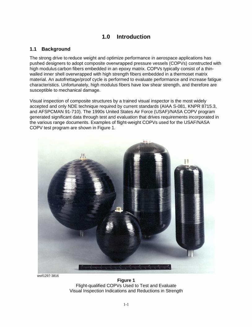
The strong drive to reduce weight and optimize performance in aerospace applications has pushed designers to adopt composite overwrapped pressure vessels (COPVs) constructed with high modulus carbon fibers embedded in an epoxy matrix. COPVs typically consist of a thin-walled inner shell overwrapped with high strength fibers embedded in a thermoset matrix material. An autofrettage/proof cycle is performed to evaluate performance and increase fatigue characteristics. Unfortunately, high modulus fibers have low shear strength, and therefore are susceptible to mechanical damage. Visual inspection of composite structures by a trained visual inspector is the most widely accepted and only NDE technique required by current standards (AIAA S-081, KNPR 8715.3, and AFSPCMAN 91-710). The 1990s United States Air Force (USAF)/NASA COPV program generated significant data through test and evaluation that drives requirements incorporated in the various range documents. Examples of flight-weight COPVs used for the USAF/NASA COPV test program are shown in Figure 1.
wstf1297-3816
Figure 1 Flight-qualified COPVs Used to Test and Evaluate
Visual Inspection Indications and Reductions in Strength

1-2
Visual NDE involves qualitative physical inspection of a composite material or component to detect gross flaws and imperfections, thus assuring compliance to the engineering design requirement that the composite is in a known stress state and no mechanical damage has occurred during processing or service. Accept/reject criteria for such defects should be given in the applicable engineering drawings, specifications, purchase orders, or contracts. If no accept/reject criteria exist, provisions described within this document may be used to drive Material Review Board (MRB) disposition. Complete visual inspection involves the review of the component’s data package to verify proper materials of construction and dimension tolerances are maintained. It also involves review of quality records (damage control plan, certificates of material conformance, etc.) to verify inspection points and engineering design are maintained. The evaluation of many NDE observations is subjective and repeatability errors can be significant, therefore errors must be known and controlled. These errors will be minimized and controlled through proper training, review of reference material, and associated certification programs. To minimize these errors, standardized inspection procedures should be implemented.
1.2 Objectives
Following the guidelines outlined in this document will provide a high level of confidence that a composite structure is maintained and verified in a known stress state. Accept/reject criteria are established in this document by definition of Level I or Level II damage. Level II damage does not necessarily REJECT the component, but provides guidance to define a discrepant or noncompliant condition. It also does not identify or ascertain the structure’s residual strength. The final disposition will be determined by MRB or project specific discrepancy reporting. Flight articles may not be completely covered by this document as distinct protocol and documentation usually exist for their control and safety. This document identifies the elements to perform a complete detailed visual inspection of the external surface of a composite structure. These procedures are best applied, but not limited, to composite structures with low factors of safety that are used for fluid storage on aerospace launch and satellite vehicles. When properly applied to the entire composite surface, this method provides wide field screening for indications that could potentially reduce the strength of the structure. Indications may be observed at any time during the life of the component and may occur during manufacturing, processing (shipping, integration, etc.), or use, therefore visual inspection will occur at numerous pre-defined points throughout the entire life of the composite structure. The credible threat analysis, inspection points, approved NDE techniques, and any associated accept/reject criteria are defined in the damage control plan (DCP) as required per existing range documents [AIAA-S081 (2006), KNPR 8715.3 (2010), and AFSPCMAN 91-710 Vol. 3, 6 (2004)]. As required per the range documents, visual inspection shall be performed by individuals that are qualified and approved to inspect and document flaws or damage on the composite surface.
1.3 Scope of Study
All personnel involved in the visual inspection of composite structures and aerospace hardware should be familiar with this document. Prior to handling any critical hardware, personnel are expected to obtain local or program certification and complete some level of training specific to
1-3
composite structures. Elements and procedures are provided for developing a mapping convention, performing photo documentation, and conducting a detailed visual inspection of the external surface of a composite structure. The following elements are mainly for composite vessels used for fluid storage on launch and satellite vehicles but may be applied to other structures and/or non-flight weight composite vessels. Specific test requirements will be conducted in accordance with approved management system records and work authorizing documents.
1.4 Technical Approach
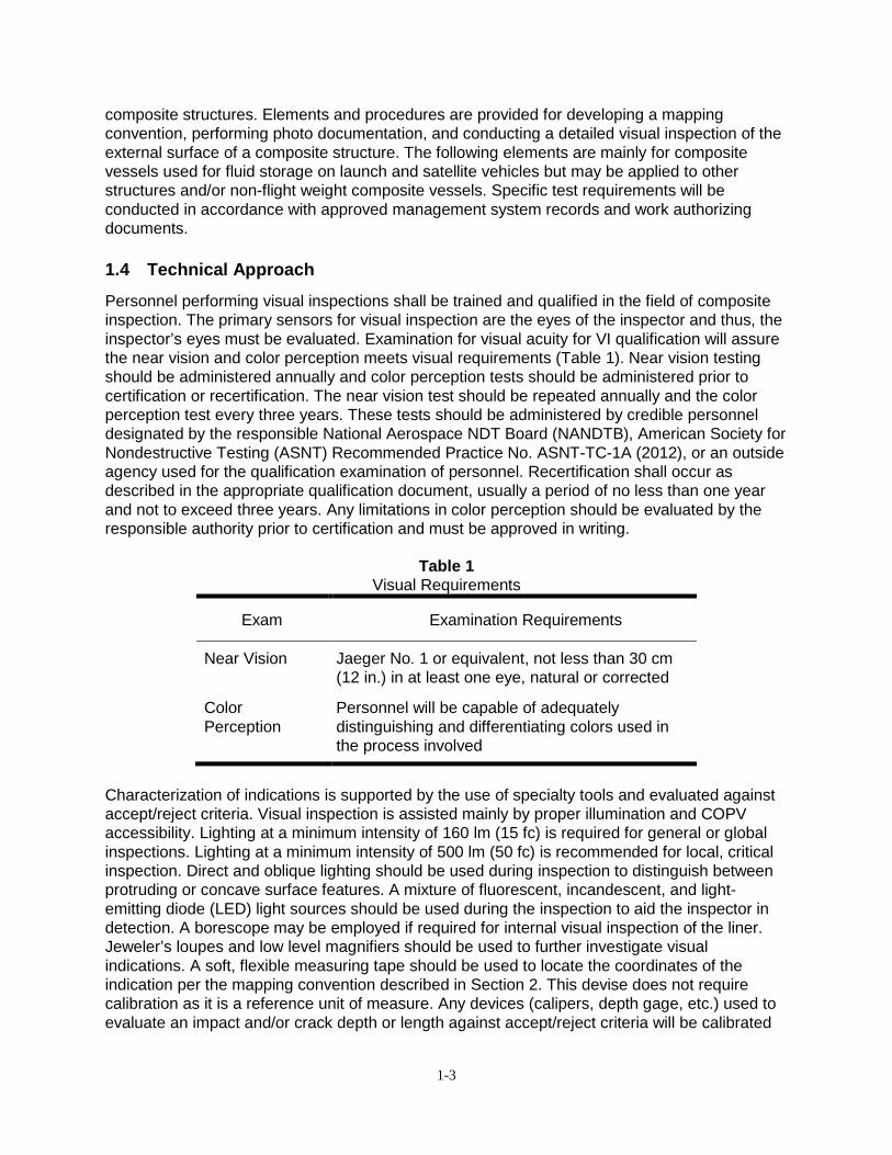
Personnel performing visual inspections shall be trained and qualified in the field of composite inspection. The primary sensors for visual inspection are the eyes of the inspector and thus, the inspector’s eyes must be evaluated. Examination for visual acuity for VI qualification will assure the near vision and color perception meets visual requirements (Table 1). Near vision testing should be administered annually and color perception tests should be administered prior to certification or recertification. The near vision test should be repeated annually and the color perception test every three years. These tests should be administered by credible personnel designated by the responsible National Aerospace NDT Board (NANDTB), American Society for Nondestructive Testing (ASNT) Recommended Practice No. ASNT-TC-1A (2012), or an outside agency used for the qualification examination of personnel. Recertification shall occur as described in the appropriate qualification document, usually a period of no less than one year and not to exceed three years. Any limitations in color perception should be evaluated by the responsible authority prior to certification and must be approved in writing.
Table 1
Visual Requirements
Exam Examination Requirements
Near Vision Jaeger No. 1 or equivalent, not less than 30 cm (12 in.) in at least one eye, natural or corrected
Color Perception
Personnel will be capable of adequately distinguishing and differentiating colors used in the process involved
Characterization of indications is supported by the use of specialty tools and evaluated against accept/reject criteria. Visual inspection is assisted mainly by proper illumination and COPV accessibility. Lighting at a minimum intensity of 160 lm (15 fc) is required for general or global inspections. Lighting at a minimum intensity of 500 lm (50 fc) is recommended for local, critical inspection. Direct and oblique lighting should be used during inspection to distinguish between protruding or concave surface features. A mixture of fluorescent, incandescent, and light-emitting diode (LED) light sources should be used during the inspection to aid the inspector in detection. A borescope may be employed if required for internal visual inspection of the liner. Jeweler’s loupes and low level magnifiers should be used to further investigate visual indications. A soft, flexible measuring tape should be used to locate the coordinates of the indication per the mapping convention described in Section 2. This devise does not require calibration as it is a reference unit of measure. Any devices (calipers, depth gage, etc.) used to evaluate an impact and/or crack depth or length against accept/reject criteria will be calibrated
1-4
or demonstrated to be within allowable tolerances when the measurement of an observation is made. Extended exposure to elevated/depressed light sources may cause fatigue and strain to the inspector and should be mitigated by appropriate illumination levels. Extended fixed focal lengths may also cause fatigue and strain to the inspector and can be mitigated by inspection durations or fixed focal length interruptions. The general application of this technique does not warrant other specific safety precautions, but hazards associated with the composite structure should be considered prior to conducting a visual inspection. The surface of the vessel may have sharp edges resulting from the manufacturing process or mechanical damage. Inspectors should use caution when handling or tactically evaluating the vessel surface. Approved gloves should be used when surface contact is required. Based on the typical COPV stored energy and use environment, the inspector should gain a full understanding of the inspection scenario. A pre-inspection worksheet should be completed prior to the inspection to help identify and mitigate potentially hazardous situations (i.e., atmospheric, stored energy, etc.). Additionally, the pre-inspection worksheet will provide invaluable data regarding component design and program documentation to the visual inspector. A pre-inspection worksheet was developed at NASA White Sands Test Facility (WSTF) and is located in Appendix B. Visual inspection is insensitive to bulk features and characteristics. This NDE method cannot yield information on the depth and extent of damage caused by an impact. Other NDE methods should be applied for better understanding. Although other methods can provide a better quantification of the damage, residual strength cannot be determined currently by these NDE techniques. Familiarity with the manufacturing process and damage tolerance of the specific component under inspection must be understood to provide adequate visual inspection screening. The impact damage tolerance of the composite overwrap will depend on the size and shape of the vessel, composite thickness (number of plys), thickness of the composite overwrap relative to the liner, pressure state and commodity, location of the impact, and geometry of the object striking the component.
1.5 Organization of the Report
This report provides a way to approach and conduct visual inspection of a composite structure. It contains information on the importance and establishment of rationale for a defined mapping convention. Elements of supporting photo documentation are provided. The approach to conducting a comprehensive visual inspection as required by existing range documents is discussed. Additionally, reporting requirements are discussed and inspection worksheets and reports templates are presented.

2-5
2.0 Mapping Convention
2.1 Purpose
A well identified and documented mapping convention is essential for all forms of NDE. The mapping convention should be established and documented in program documentation (procurements contract, DCP, etc.), manufacturer’s design documents (drawings, inspection reports, etc.) and at a minimum, on the visual inspection report. The mapping convention provides a common coordinate system to measure the location of a reported observation. The coordinate system must be tied to a permanent visible feature. This feature is often a label, keyway, or scribe onto a boss/port. This basic convention applies to all future visual inspections and provides for direct comparison and evaluation of any subsequent NDE interrogation.
2.2 Mapping Convention
Review manufacturing design drawings and/or program documents to determine if a mapping convention exists for the component. If a mapping convention is established, document it on a visual inspection report similar to that located in Appendix C. If the predetermined mapping convention is applicable, the remaining steps in this section are not required. The mapping convention coordinate system consists of a rotational coordinate in units of degrees and a lateral measurement in inches. The origin/datum of the coordinate system is often determined by one of the ported ends of the component and referred to as the A-End. Determine which end to classify as the A-End. Base this decision on permanent markings that exist on the component. Evaluate the markings to ensure they will not be obscured during handling or use. If required, gain approval from the composite structure owner to permanently indicate a zero degree mark on the A-End of the component. Record the description of the A-End mark on the inspection report and in appropriate program records. In addition, specify the positive direction of the rotation axis (usually clockwise looking at the A-End). Document on the visual inspection report the exact location the lateral measurements will be taken from. This is often the edge of a permanent feature towards the A-End, e.g., the composite termination or base of the boss. The arc length for all recorded indications will be measured from this reference location. The lateral and circumferential values must be measured and documented on the visual inspection report.

3-6
3.0 Photo Documentation
3.1 Purpose
The purpose of photo documentation is to provide a permanent record of the shipping container’s condition as received, and observations made by the qualified visual inspector. It provides imagery to accompany the composite structure in the associated data pack. This provides future inspectors a visual record for comparative assessments. If damage is monitored through the life of the component, this documentation will be invaluable. Additionally, this data is useful to discuss observations in the absence of the composite structure.
3.2 Elements of Photo Documentation
It is important to identify components and indications that require photo documentation. Ensure serial number (S/N) and model number (M/N), if possible, are identified and recorded in the image or permanent traceability is identified in the slug number of the image. Production or program proprietary information may be required and therefore must be separated from the image and located in the work authorizing document associated with the image slug number. Place unit of measurement and shot/item identifier in every image, at a minimum. If component information cannot be recorded in the image, the photo should contain data to ensure traceability to the specific composite structure, e.g., photo identification slug number.
3.3 Elements of Imaging
The elements of imaging are to provide total and complete photo documentation of the component. This may occur at all phases of the component’s lifetime and may include the shipping container and its packaging contents. In general, after the as-received photos are collected, the component does not require photos unless Level II damage is observed. It is recommended that the vessel be photographed prior to and after integration to preserve the component’s condition for record. If instrumentation, installation, or shielding that may obscure the surface is being placed on or around the vessel, it is important to photograph the areas of interest before they are hidden. This will preclude questions or concerns regarding the vessel’s integrity and/or known stress state after the areas are inaccessible. The imaging should follow all the lighting recommendations used in the visual inspection section. The image shall be clear, free from distracting objects, and in focus. Multiple angles are beneficial and can be invaluable after composite structure processing has occurred. Orient the structure in different lighting, changing the light and turning off the flash as necessary to reduce glare and reflections. For detailed photo documentation of specific indications, the macro function of the camera may be necessary. For macro images of a damage site, ensure adequate lighting and a steady camera. Use nearby objects or a tripod to stabilize the camera. If the indication is in an area of minor contrast, use the unit of measure to contrast the indication and allow the camera to find a focal location. Use a camera that has the resolution to clearly document the indication at the appropriate focal length. This will need to be about 0.02 in. (.5 mm). High resolution cameras, tripods, and macro lenses used in a studio are preferred, but not necessarily required. Most imaging will occur in the field under less than perfect conditions and therefore it may be difficult to obtain high quality images. Multiple images and settings are recommended and close attention to the camera’s view screen is suggested.

3-7
3.3.1 Shipping Container Photo documentation of the shipping container may be needed per program or DCP requirements. This type of documentation provides a general record of container condition (Figure 2). It may be performed as a measure of completeness or as required if damage is observed. Items to consider for photo documentation include, but are not limited to, humidity recorders and shock-rider impact detectors (Figure 3). Any container damage that may affect the components within the container should be documented (Figure 4). This can provide component orientation records that will be useful for the visual inspector to ensure that any damage to the container was not translated to the component inside.
wstf1007e08290
Figure 2 Shipping Container

3-8
wstf07011638
Figure 3 Tripped Shock-Rider
wstf0212e02568
Figure 4 Shipping Container Damage
If shipping container photography is required, collect images per the following guidelines:
• Collect images that represent all sides and top of box or crate. Ensure that the condition
of any level indicators or shock-riders is captured in the images. • Open container as prescribed and photograph at multiple steps to document condition of
packing material. Ensure that the condition and results of any monitoring devises/instrumentation such as humidity recorders are captured.
• Continue to unpack material with a systematic approach and conduct photo documentation as layers of material are removed.
3-9
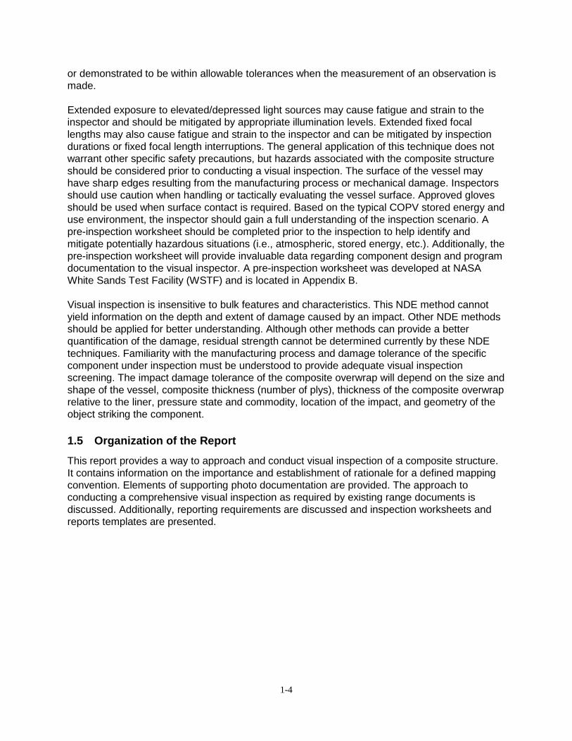
3.3.2 Component Receipt Photo documentation at the receiving phase establishes documentation of the component’s baseline condition prior to any handling, testing, or use. It provides record of the component in the as-received condition. This is important data that should be included in the data package and made available to program and inspection personnel to aid in reporting, future inspections, and use if an MRB should occur. Complete photo documentation of the component should be performed with the following images as a minimum (Figures 5-6).
wstf1211e12646
Figure 5 Overall A-End with 0o ~Top Dead Center (TDC)
3-10
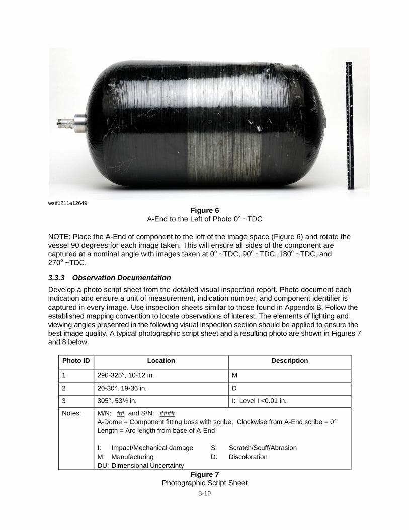
wstf1211e12649
Figure 6 A-End to the Left of Photo 0° ~TDC
NOTE: Place the A-End of component to the left of the image space (Figure 6) and rotate the vessel 90 degrees for each image taken. This will ensure all sides of the component are captured at a nominal angle with images taken at 0o ~TDC, 90o ~TDC, 180o ~TDC, and 270o ~TDC.
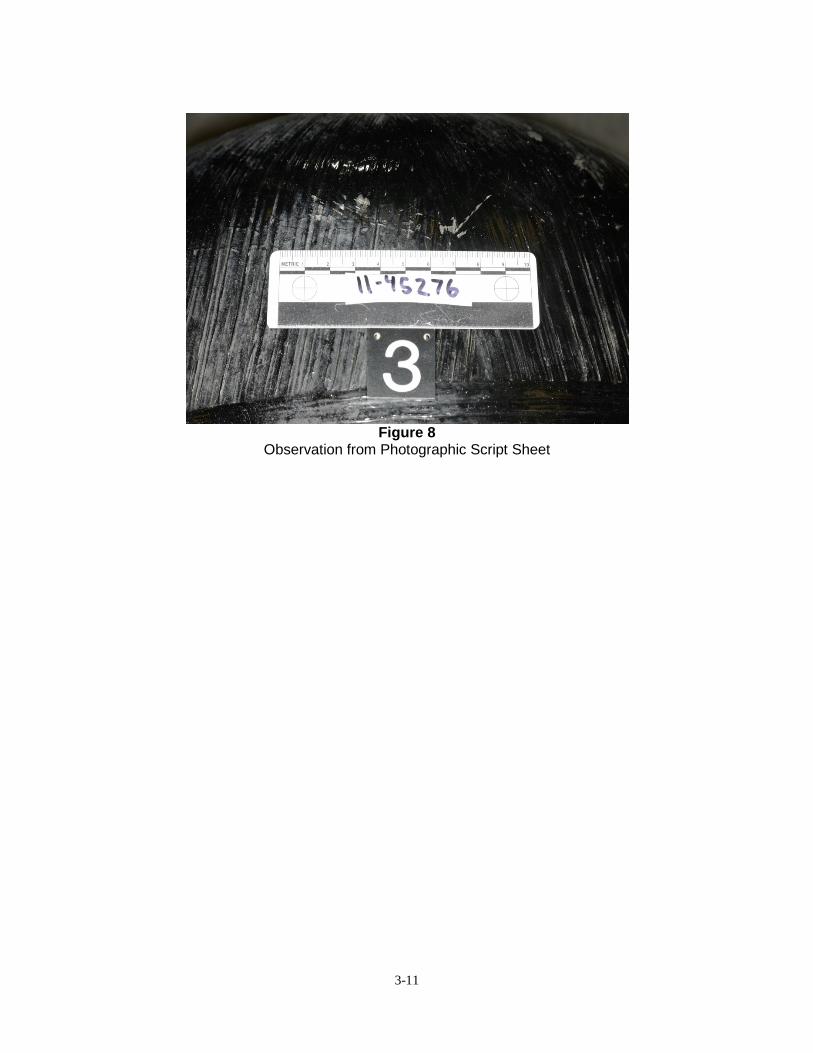
3.3.3 Observation Documentation Develop a photo script sheet from the detailed visual inspection report. Photo document each indication and ensure a unit of measurement, indication number, and component identifier is captured in every image. Use inspection sheets similar to those found in Appendix B. Follow the established mapping convention to locate observations of interest. The elements of lighting and viewing angles presented in the following visual inspection section should be applied to ensure the best image quality. A typical photographic script sheet and a resulting photo are shown in Figures 7 and 8 below.
Photo ID Location Description
1 290-325°, 10-12 in. M
2 20-30°, 19-36 in. D
3 305°, 53½ in. I: Level I <0.01 in.
Notes: M/N: ## and S/N: #### A-Dome = Component fitting boss with scribe, Clockwise from A-End scribe = 0° Length = Arc length from base of A-End I: Impact/Mechanical damage S: Scratch/Scuff/Abrasion M: Manufacturing D: Discoloration DU: Dimensional Uncertainty
Figure 7 Photographic Script Sheet
3-11
Figure 8
Observation from Photographic Script Sheet

4-12
4.0 Visual Inspection These guidelines provide direction to perform a detailed visual inspection of the external composite surface of an aerospace component. A basic level of training and experience specific to the manufacturing of composite structures is required prior to qualifying as a composite visual inspector. The vessel-specific reference documents must be reviewed and understood prior to performing a detailed visual inspection. This provides the inspector with information regarding any accept/reject criteria, known/recorded observations, special reporting requirements, and the accepted mapping convention. After meeting all program and area certification requirements, the composite structure may be scheduled for inspection. Work authorizing documents, inspection tools, and inspection reports should be gathered and available prior to beginning the inspection. The data and/or mapping convention must first be identified or established. The visual inspection should be conducted initially from a global/far field of view. The inspection can then be performed at a local/near field of view. Indications can be located, characterized, and reported. If accept/reject criteria exist, the indications can be evaluated and reported accordingly, otherwise indications that affect fiber or structural integrity, as understood by the inspector, must be reported for MR. Visual inspection can be enhanced and extended by the use of various tools. Inspection tools may require approval or need to be inventoried prior to entering restricted or controlled areas. Once the inspection is complete, the VI reports are signed, dated, and filed as required by the DCP and/or program.
4.1 Visual Inspection Guidelines
Visual inspection of a composite structure follows general guidelines prescribed for the visual inspection of any hardware or component. The inspector must have experience and/or training specific to the manufactured composite structure being inspected, including methods of construction, material selection, and performance requirements. Component receipt will be per existing program requirements or the associated DCP. Review available original equipment manufacturer (OEM) records, program design requirements, DCPs, and all previous inspection reports. Review work authorizing documents to identify inspection requirements/limitations, hardware identification, accept/reject criteria, component accessibility, area access controls, and personal protective equipment (PPE). If possible, identify and document the component mapping convention prior to starting the inspection. Ensure all required personal certifications are current and completed. As required, coordinate inspection with appropriate program personnel (i.e., project management, hardware owner, area attendant). Gather inspection tools and reporting documents and assemble at the entrance of the inspection area. Set up for the scheduled inspection at the specific component’s location. Locate and positively identify the composite structure that requires inspection. Verify the model and serial number of the composite structure because lack of proper identification is generally a condition for vessel rejection. Determine the orientation of the vessel as determined by the mapping convention. If this is not provided or cannot be determined, a new mapping convention must be established and documented on the VI sheet. Evaluate the entire inspection environment with special attention to available lighting and vessel accessibility. If the lighting is insufficient, establish better lighting. Request more illumination from facility personnel or use handheld devices. Evaluate the composite structure’s accessibility to determine an approach that ensures 100 percent of the surface is inspected. This approach will define discrete areas of inspection (i.e., dome, hoop, quadrants, etc.) and any special inspection tools. If vessel is still in the shipping container or has protective covers installed, a general inspection of the container

4-13
and/or protective covers should be performed and any indications reported. A detailed inspection report is not required, but if any damage or penetration is observed, a record should be issued to document the extent and location of the damage. If mechanical damage is observed on the container or component protection shield, extra care and scrutiny should be applied during the inspection to ensure that damage is limited to the container/shield. A discrepancy report may be required at this time. Remove protective covers and shipping materials as required to access the composite structure. Perform a global/far field inspection looking for obvious gross indications. This will give the inspector a good idea of the general condition of the vessel. Inspect the areas in the systematic manner developed during the pre-inspection evaluation. It is recommended to break up the component into discrete sections (e.g., A-End dome, hoop/barrel, or quadrants) to ensure the entire surface is visually inspected. Another approach is to inspect along complete latitudes or longitudes. This inspection should be applied in adequate lighting to the entire surface of the vessel at roughly arm’s length (18-24 in.). Some observations are more apparent during global/far field inspection and should be noted for more detailed interrogation during local/near field inspection. Inspect a high-gloss surface at angles less than 45 degrees and a rough-textured surface at a direct viewing angle. When possible, inspect along linear surfaces such as the barrel section. Any areas that are hidden or obscured from view should be accepted prior to closeout and need to be recorded on a detailed visual inspection report. Any areas that are obscured or cannot be visually inspected must be documented on the inspection record by the inspector. Use established mapping convention to identify any areas where inspection cannot be conducted. Perform and document the detailed local/near field visual inspection on report/inspection log sheet. Local/near field inspection may be aided by magnification, mirrors, and a movable light source. The inspector should change the vantage point with respect to the vessel’s orientation and light source to increase the ability to detect indications. The visual inspector should vary the inspection focal length from a distance of 24 in. down to the composite surface. Thoroughly inspect the entire composite surface for Level I or Level II damage. Indications will be evaluated against documented accept/reject criteria. If Level I or Level II damage is observed, it should be characterized and recorded on the inspection report. The location will be measured and tied directly to the established mapping convention. Important characteristics should include type of indication, affected area, and measured depth. Accompany the visual inspection report with a sketch or photograph of the indication. It is recommended to develop a photographic script sheet that maps the exact location with a brief description of the indication as described in Section 2. Follow steps in this document for recommended lighting, inspection focal length, and image content to ensure quality photo documentation. Various types of indications are best described by one of the following:
1. Scratch/scuff/abrasion (Level I or Level II) 2. Impact/Mechanical Damage (Level I or Level II) 3. Discoloration (Level I or Level II) 4. Manufacturing (Level I or Level II)
Scratch/scuff/abrasion that is Level I damage is described as being limited to the resin/matrix. Micro-cracking is a type of this damage and normally the bottom of the indication is whitish in color. Known or suspected Level I impact/mechanical damage cannot show evidence of broken

4-14
fibers/tow. Data from the USAF/NASA test program demonstrated that if impact/mechanical damage is observed but no broken/cracked tows are visible, the residual strength was not affected at the service pressure stress levels. If acoustic impendence testing indicates subsurface delamination, the damage level should be increased to Level II and the nonconformity recorded. Level I discoloration is limited to the resin/matrix. Examples include resin-related dulling, paint overspray, compatible adhesives/resins, or matrix crazing. Level I manufacturing indications include tow terminations, excess resin, resin bubbles, entrained fibers, or minor ply disorientation. Examples of Level I damage are shown in Appendix A, Figures A-1 through A-4. This level of damage does not affect the residual strength of the component and other than good documentation practice, no further action is required. Level II scratch/scuff/abrasion is described as any damage that affects the carbon tows. Level II impact/mechanical damage is often associated with a dent or impression and associated broken or cracked tows or partial tows. Usually Level II impact/mechanical damage has areas of delamination that can be detected by acoustic impedance NDT (i.e., coin tapping). Consult OEM and/or AHJ if this method of NDT is required. Discoloration that is Level II shows evidence of extreme epoxy attack and laminate exposure/damage. Level II manufacturing indications are demonstrated by gross ply disorientation, the absence of resin, delaminating tow terminations, and potentially the lack of proper component identification. If Level II damage is observed, a discrepancy or nonconformance report will be issued and the component must be released/approved per MRB disposition prior to further processing. Unless otherwise specified, indications involving cut or broken fibers or tows on aerospace composite structures require MRB disposition for further use. Examples of Level II damage are shown in Appendix A, Figures A-5 through A-7. Compare the physical dimensions of the indication to the accept/reject criteria established first by the AHJ/program documentation, second by the OEM, and third by the Compressed Gas Association (CGA) 6.4-2007 (if applicable). If no accept/reject criteria exist for the specific vessel design, then any Level II damage requires MRB disposition. If Level II damage is observed on a pressurized vessel, the inspection should be terminated immediately and the area secured until program and safety personnel are notified. This often results in the venting of the vessel to reduce risk of catastrophic failure until a final disposition can be made. If the vessel is unpressurized, continue with the visual inspection until 100 percent of the exposed composite surface is inspected. Return the vessel to its pre-inspection configuration. The inspection report will be signed and dated by the approved visual inspector. The visual inspection report will be filed as a quality document. This report may be required for vessel closeout and flight readiness review, therefore it should be copied and placed in the vessel, subsystem, or vehicle data pack. Inspections performed after integration and/or instrumentation may yield areas inaccessible to the inspectors. These areas must be visually inspected and “CLOSED OUT” prior to being obscured from view. Documentation must exist to preclude processing or flight constraints. This inspection technique is capable of detecting a flaw size corresponding to a 90 percent probability of detection at a 95 percent confidence level, but testing must be performed to determine accept/reject criteria. If accept/reject criteria exist, they must be documented at the program level with concurrence by the OEM. This testing is specific to a particular vessel design and may or may not apply to other vessel designs. Visual inspection is generally not a quantitative inspection technique and must be documented to initiate an MRB.

4-15
Damage indicators may also be applied as a part of the vessel design. These indicators may consist of specialized coatings and/or additional overwraps. Specialized coatings may indicate damage under black light inspection when chipped from the surface or contain microspheres that rupture and “bleed” when impacted. A mechanical damage indication to a black light sensitive coating is shown illuminated and non-illuminated in Figures A-9 and A-10, respectively. These coatings must be characterized and their sensitivity thoroughly understood by the OEM, and that information conveyed to the visual inspector. Additional wraps, often in the form of fiberglass, may show indication of impact. The resulting reduction in strength related to a visible indication on the indicator wraps must also be characterized and thoroughly understood by OEM with that information conveyed to the visual inspector. An example of mechanical damage to an indicating fiberglass wrap is shown in Figure A-8. Personnel performing visual inspection should have a good understanding of the specific OEM’s manufacturing process, resulting acceptable surface conditions, and the effects of mechanical damage.

5-16
5.0 Reporting A qualitative description of any defects should be provided, as described in Section 4.1, along with corresponding quantitative details (location, size [length and depth], and size distribution). For archival and reference purposes, inspection sheets with photo and/or video documentation is recommended. Good documentation procedures are adopted through certification and should be followed. Reporting log sheets will be developed by the program or may be adopted using the visual inspection record in Appendix C. The hardware specific requirements will be defined in the program DCP. The DCP is required by various range documents (KNPR 8715.3 and AFSPCMAN 91-710) and is the responsibility of the design agency, generally the prime contractor. It should list any accept/reject criteria, accepted NDE techniques, inspection points, credible threat analyses, and reporting requirements. Inspection reports will be maintained by the program, OEM, or S&MA department, as required, for the life of the composite structure. It is recommended to maintain records for three years after the program is complete; however, specific program requirements may override this recommendation.

6-17
6.0 References AFSPCMAN91-710; Vol. 3. Range Safety User Requirements Manual Volume 3 - Launch
Vehicles, Payloads, and Ground Support Systems Requirements, Air Force Space Command Manual, U.S. Department of Defense, July 2004.
AFSPCMAN 91-710; Vol. 6. Range Safety User Requirements Manual Volume 6 - Ground and
Launch Personnel, Equipment, Systems, and Material Operations Safety Requirements, Air Force Space Command Manual, U.S. Department of Defense, July 2004.
AIAA S-081A-2006. Space Systems – Composite Overwrapped Pressure Vessels (COPVs),
American Institute of Aeronautics and Astronautics, Reston, Virginia, January 1, 2006. ASNT-TC-1A. Recommended Practice for Personnel Qualification and Certification in
Nondestructive Testing, American Society for Nondestructive Testing, Columbus, Ohio, April 1, 2012.
CGA C-6.4-2007. Methods for External Visual Inspection of Natural Gas Vehicle (HGV) and
Hydrogen Vehicle (HV) Fuel Containers and Their Installations, Third Edition, Compressed Gas Association, Inc., Chantilly, Virginia, January 2008.
KNPR 8715.3, Rev. G, KSC Safety Practices Procedural Requirements, Kennedy Space
Center, Florida, June 1, 2010. Tapphorn, R., W. Ross, H. Beeson, and H. Johnson. Impact Damage Effects and Control
Applied to Composite Overwrapped Pressure Vessels. TR-806-001, NASA Johnson Space Center White Sands Test Facility, Las Cruces, New Mexico, July 29, 1998.
WSTF. Visual Inspector: Composite Overwrapped Pressure Vessel Damage Detection Course,
NASA Johnson Space Center White Sands Test Facility, Las Cruces, New Mexico, June 2012.

Appendix A
Photo Documentation of Level I and Level II Damage

A-1
Figure A-1
Level I Manufacturing (Tow Termination)
Figure A-2
Level I Manufacturing (Matrix Indications)
0.5 in.
0.5 in.

A-2
Figure A-3
Level I Scratch/Scuff/Abrasion (Cut)
Figure A-4
Level I Scratch/Scuff/Abrasion (Matrix Grinding)
0.5 in.
1 in.

A-3
Figure A-5
Level II Scratch/Scuff/Abrasion (Cut Tows)
Figure A-6
Level II Impact/Mechanical Damage (Broken Tows)
0.5 in.
1 in.

A-4
wstf0496-1111
Figure A-7 Level II Discoloration (Chemical Exposure)
wstf0712e08804
Figure A-8 Level II Impact/Mechanical Damage
(Specialized Coating Black Light Illumination)
1 in.

A-5
wstf0712e08803
Figure A-9 Level II Impact/Mechanical Damage
(Specialized Coating without Black Light Illumination)
wstf0712e08800
Figure A-10 Level II Impact/Mechanical Damage (Indication Wrap)

Appendix B
Pre-Inspection Worksheet
B-1
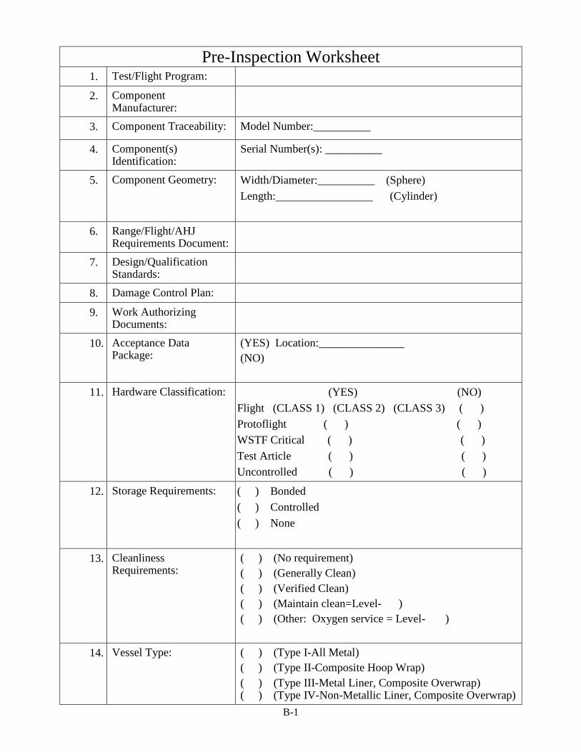
Pre-Inspection Worksheet 1. Test/Flight Program:
2. Component Manufacturer:
3. Component Traceability: Model Number:__________
4. Component(s) Identification:
Serial Number(s): __________
5. Component Geometry: Width/Diameter:__________ (Sphere) Length:_________________ (Cylinder)
6. Range/Flight/AHJ Requirements Document:
7. Design/Qualification Standards:
8. Damage Control Plan:
9. Work Authorizing Documents:
10. Acceptance Data Package:
(YES) Location:_______________ (NO)
11. Hardware Classification: (YES) (NO) Flight (CLASS 1) (CLASS 2) (CLASS 3) ( ) Protoflight ( ) ( ) WSTF Critical ( ) ( ) Test Article ( ) ( ) Uncontrolled ( ) ( )
12. Storage Requirements: ( ) Bonded ( ) Controlled ( ) None
13. Cleanliness Requirements:
( ) (No requirement) ( ) (Generally Clean) ( ) (Verified Clean) ( ) (Maintain clean=Level- ) ( ) (Other: Oxygen service = Level- )
14. Vessel Type:
( ) (Type I-All Metal) ( ) (Type II-Composite Hoop Wrap) ( ) (Type III-Metal Liner, Composite Overwrap) ( ) (Type IV-Non-Metallic Liner, Composite Overwrap)

B-2
Pre-Inspection Worksheet ( ) (Type V-Composite Liner and Overwrap)
15. Materials of Construction:
Fiber Type:_________________ Resin Type:_________________ Liner Material:_______________
16. Visual Inspection Type:
( ) (Internal) ( ) (External)
17. Mapping Convention: A-End:__________ B-End:__________ 00 : Measured CCW/CW on __ -End from _____ Latitudinal: Measured from _____ on __-End)
18. Operating/Design loads: Maximum Operating Pressure: psi Service Pressure: psi Autofrettage/Proof Pressure: psi Design Burst Pressure: psi
19. Approved service media:
20. Hazard Analysis: ( ) High Pressure ( ) Hypergolic ( ) Oxygen System ( ) Asphyxiate
21. Safety Requirements: (YES) List:_______________ (NO)
22. PPE Requirements: (YES) List:_______________ (NO)
23. Special Training:
(YES) List:_______________ (NO)
24. Launch Site Pressure Test (1.1xMDP):
(YES) (NO)
25. Photo Documentation: (YES) (NO)
B-3
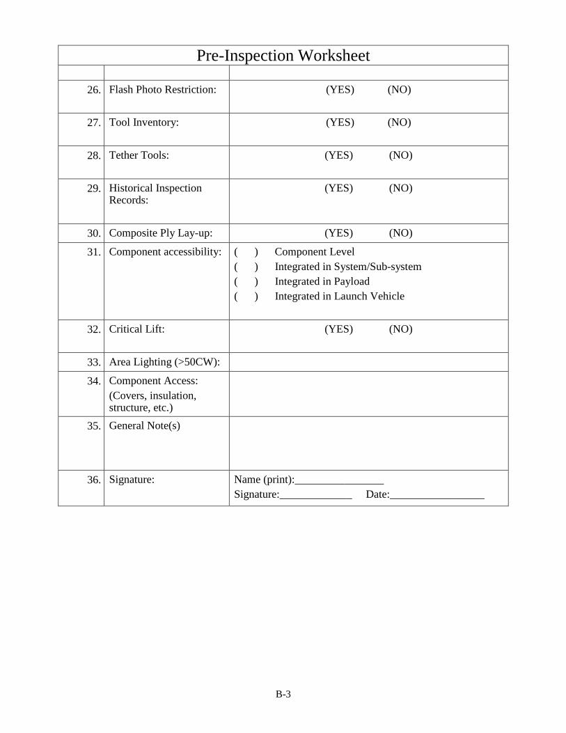
Pre-Inspection Worksheet
26. Flash Photo Restriction:
(YES) (NO)
27. Tool Inventory:
(YES) (NO)
28. Tether Tools:
(YES) (NO)
29. Historical Inspection Records:
(YES) (NO)
30. Composite Ply Lay-up: (YES) (NO)
31. Component accessibility:
( ) Component Level ( ) Integrated in System/Sub-system ( ) Integrated in Payload ( ) Integrated in Launch Vehicle
32. Critical Lift:
(YES) (NO)
33. Area Lighting (>50CW):
34. Component Access: (Covers, insulation, structure, etc.)
35. General Note(s)
36. Signature: Name (print):________________ Signature:_____________ Date:_________________

Appendix C
Visual Inspection Record

C-1
NASA White Sands Test Facility Laboratories Office
P.O. Box 20 Las Cruces, NM 88004 575-524-5723
Manufacturer: Vessel Geometry: Model Number: WSTF Number: Serial Number: Dimensions: A-End= B-End=
Longitude: CW from ( -End) with 00 at Latitude: Arc length from on ( -End)
Inspector Name:
Date:
Line Location Description 1
2
3
4
5
6
7
8
9
10
11
12
13
14
15
16
Notes
I: Impact/Mechanical damage S: Scratch/Scuff/Abrasion M: Manufacturing D: Discoloration DU: Dimensional Uncertainty

C-2
Cylinder Map
A-End
B-End
A-End=00= Clockwise A-End00 1800

C-3
Spherical Map