Electronics- Zener Diodes and Photodiodesdenethor.wlu.ca/pc320/lectures/zenbeam.pdf ·...
82
Diodes Zener diodes Photodiodes Optical Isolation Electronics Zener Diodes and Photodiodes Terry Sturtevant Wilfrid Laurier University September 26, 2017 Terry Sturtevant Electronics Zener Diodes and Photodiodes
Transcript of Electronics- Zener Diodes and Photodiodesdenethor.wlu.ca/pc320/lectures/zenbeam.pdf ·...

DiodesZener diodesPhotodiodes
Optical Isolation
ElectronicsZener Diodes and Photodiodes
Terry Sturtevant
Wilfrid Laurier University
September 26, 2017
Terry Sturtevant Electronics Zener Diodes and Photodiodes
DiodesZener diodesPhotodiodes
Optical Isolation
Basic Diode OperationApplication: Clamping
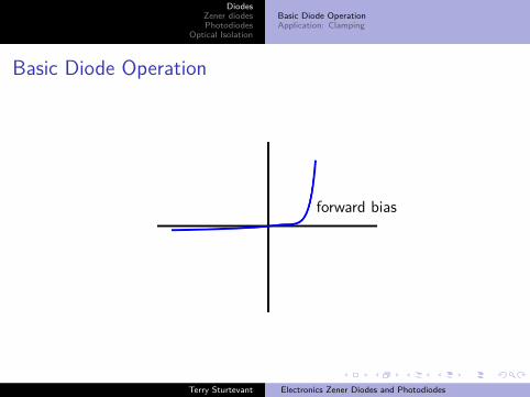
Basic Diode Operation
forward bias
Terry Sturtevant Electronics Zener Diodes and Photodiodes

DiodesZener diodesPhotodiodes
Optical Isolation
Basic Diode OperationApplication: Clamping
Basic Diode Operation
reverse bias
Terry Sturtevant Electronics Zener Diodes and Photodiodes
DiodesZener diodesPhotodiodes
Optical Isolation
Basic Diode OperationApplication: Clamping
The diode will conduct when it is forward biased when theinput voltage goes above about 0.7V .
The diode will not conduct when it is reverse biased until theinput voltage goes above about the reverse breakdownvoltage, which is typically large.
Terry Sturtevant Electronics Zener Diodes and Photodiodes
DiodesZener diodesPhotodiodes
Optical Isolation
Basic Diode OperationApplication: Clamping
The diode will conduct when it is forward biased when theinput voltage goes above about 0.7V .The diode will not conduct when it is reverse biased until theinput voltage goes above about the reverse breakdownvoltage, which is typically large.
Terry Sturtevant Electronics Zener Diodes and Photodiodes
DiodesZener diodesPhotodiodes
Optical Isolation
Basic Diode OperationApplication: Clamping
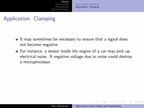
Application: Clamping
It may sometimes be necessary to ensure that a signal doesnot become negative.For instance, a sensor inside the engine of a car may pick upelectrical noise. A negative voltage due to noise could destroya microprocessor.To avoid this, the signal may be clamped so that it nevergoes below zero.This can be done using a diode.
Terry Sturtevant Electronics Zener Diodes and Photodiodes

DiodesZener diodesPhotodiodes
Optical Isolation
Basic Diode OperationApplication: Clamping
Application: Clamping
It may sometimes be necessary to ensure that a signal doesnot become negative.
For instance, a sensor inside the engine of a car may pick upelectrical noise. A negative voltage due to noise could destroya microprocessor.To avoid this, the signal may be clamped so that it nevergoes below zero.This can be done using a diode.
Terry Sturtevant Electronics Zener Diodes and Photodiodes
DiodesZener diodesPhotodiodes
Optical Isolation
Basic Diode OperationApplication: Clamping
Application: Clamping
It may sometimes be necessary to ensure that a signal doesnot become negative.For instance, a sensor inside the engine of a car may pick upelectrical noise. A negative voltage due to noise could destroya microprocessor.
To avoid this, the signal may be clamped so that it nevergoes below zero.This can be done using a diode.
Terry Sturtevant Electronics Zener Diodes and Photodiodes

DiodesZener diodesPhotodiodes
Optical Isolation
Basic Diode OperationApplication: Clamping
Application: Clamping
It may sometimes be necessary to ensure that a signal doesnot become negative.For instance, a sensor inside the engine of a car may pick upelectrical noise. A negative voltage due to noise could destroya microprocessor.To avoid this, the signal may be clamped so that it nevergoes below zero.
This can be done using a diode.
Terry Sturtevant Electronics Zener Diodes and Photodiodes

DiodesZener diodesPhotodiodes
Optical Isolation
Basic Diode OperationApplication: Clamping
Application: Clamping
It may sometimes be necessary to ensure that a signal doesnot become negative.For instance, a sensor inside the engine of a car may pick upelectrical noise. A negative voltage due to noise could destroya microprocessor.To avoid this, the signal may be clamped so that it nevergoes below zero.This can be done using a diode.
Terry Sturtevant Electronics Zener Diodes and Photodiodes

DiodesZener diodesPhotodiodes
Optical Isolation
Basic Diode OperationApplication: Clamping
Clamping a signal
Terry Sturtevant Electronics Zener Diodes and Photodiodes

DiodesZener diodesPhotodiodes
Optical Isolation
Basic Diode OperationApplication: Clamping
Vi
Rd
Vo
Terry Sturtevant Electronics Zener Diodes and Photodiodes
DiodesZener diodesPhotodiodes
Optical Isolation
Basic Diode OperationApplication: Clamping
The diode will conduct once it is forward biased.
The output voltage will follow the input until the input goesbelow about −0.7V .From then on the output will not decrease.(This slight negative voltage will not be a problem for mostelectronics.)The resistor should be chosen so that the maximum currentthrough the diode is within the specified limits.
Terry Sturtevant Electronics Zener Diodes and Photodiodes
DiodesZener diodesPhotodiodes
Optical Isolation
Basic Diode OperationApplication: Clamping
The diode will conduct once it is forward biased.The output voltage will follow the input until the input goesbelow about −0.7V .
From then on the output will not decrease.(This slight negative voltage will not be a problem for mostelectronics.)The resistor should be chosen so that the maximum currentthrough the diode is within the specified limits.
Terry Sturtevant Electronics Zener Diodes and Photodiodes

DiodesZener diodesPhotodiodes
Optical Isolation
Basic Diode OperationApplication: Clamping
The diode will conduct once it is forward biased.The output voltage will follow the input until the input goesbelow about −0.7V .From then on the output will not decrease.
(This slight negative voltage will not be a problem for mostelectronics.)The resistor should be chosen so that the maximum currentthrough the diode is within the specified limits.
Terry Sturtevant Electronics Zener Diodes and Photodiodes

DiodesZener diodesPhotodiodes
Optical Isolation
Basic Diode OperationApplication: Clamping
The diode will conduct once it is forward biased.The output voltage will follow the input until the input goesbelow about −0.7V .From then on the output will not decrease.(This slight negative voltage will not be a problem for mostelectronics.)
The resistor should be chosen so that the maximum currentthrough the diode is within the specified limits.
Terry Sturtevant Electronics Zener Diodes and Photodiodes

DiodesZener diodesPhotodiodes
Optical Isolation
Basic Diode OperationApplication: Clamping
The diode will conduct once it is forward biased.The output voltage will follow the input until the input goesbelow about −0.7V .From then on the output will not decrease.(This slight negative voltage will not be a problem for mostelectronics.)The resistor should be chosen so that the maximum currentthrough the diode is within the specified limits.
Terry Sturtevant Electronics Zener Diodes and Photodiodes

DiodesZener diodesPhotodiodes
Optical Isolation
Application: ClippingCalculating Resistance
Zener diodes
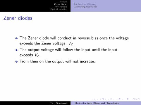
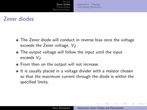
The Zener diode will conduct in reverse bias once the voltageexceeds the Zener voltage, VZ .The output voltage will follow the input until the inputexceeds VZ .From then on the output will not increase.It is usually placed in a voltage divider with a resistor chosenso that the maximum current through the diode is within thespecified limits.
Terry Sturtevant Electronics Zener Diodes and Photodiodes

DiodesZener diodesPhotodiodes
Optical Isolation
Application: ClippingCalculating Resistance
Zener diodes
The Zener diode will conduct in reverse bias once the voltageexceeds the Zener voltage, VZ .
The output voltage will follow the input until the inputexceeds VZ .From then on the output will not increase.It is usually placed in a voltage divider with a resistor chosenso that the maximum current through the diode is within thespecified limits.
Terry Sturtevant Electronics Zener Diodes and Photodiodes
DiodesZener diodesPhotodiodes
Optical Isolation
Application: ClippingCalculating Resistance
Zener diodes
The Zener diode will conduct in reverse bias once the voltageexceeds the Zener voltage, VZ .The output voltage will follow the input until the inputexceeds VZ .
From then on the output will not increase.It is usually placed in a voltage divider with a resistor chosenso that the maximum current through the diode is within thespecified limits.
Terry Sturtevant Electronics Zener Diodes and Photodiodes
DiodesZener diodesPhotodiodes
Optical Isolation
Application: ClippingCalculating Resistance
Zener diodes
The Zener diode will conduct in reverse bias once the voltageexceeds the Zener voltage, VZ .The output voltage will follow the input until the inputexceeds VZ .From then on the output will not increase.
It is usually placed in a voltage divider with a resistor chosenso that the maximum current through the diode is within thespecified limits.
Terry Sturtevant Electronics Zener Diodes and Photodiodes
DiodesZener diodesPhotodiodes
Optical Isolation
Application: ClippingCalculating Resistance
Zener diodes
The Zener diode will conduct in reverse bias once the voltageexceeds the Zener voltage, VZ .The output voltage will follow the input until the inputexceeds VZ .From then on the output will not increase.It is usually placed in a voltage divider with a resistor chosenso that the maximum current through the diode is within thespecified limits.
Terry Sturtevant Electronics Zener Diodes and Photodiodes

DiodesZener diodesPhotodiodes
Optical Isolation
Application: ClippingCalculating Resistance
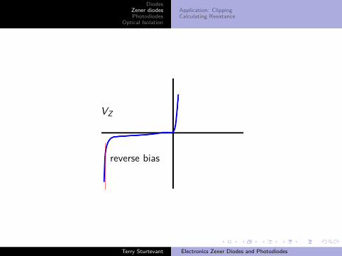
reverse bias
Terry Sturtevant Electronics Zener Diodes and Photodiodes
DiodesZener diodesPhotodiodes
Optical Isolation
Application: ClippingCalculating Resistance
reverse bias
VZ
Terry Sturtevant Electronics Zener Diodes and Photodiodes
DiodesZener diodesPhotodiodes
Optical Isolation
Application: ClippingCalculating Resistance
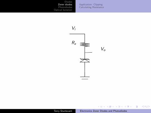
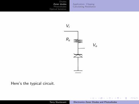
Vi
RzVo
Here’s the typical circuit.
Terry Sturtevant Electronics Zener Diodes and Photodiodes
DiodesZener diodesPhotodiodes
Optical Isolation
Application: ClippingCalculating Resistance
Vi
RzVo
Here’s the typical circuit.
Terry Sturtevant Electronics Zener Diodes and Photodiodes
DiodesZener diodesPhotodiodes
Optical Isolation
Application: ClippingCalculating Resistance
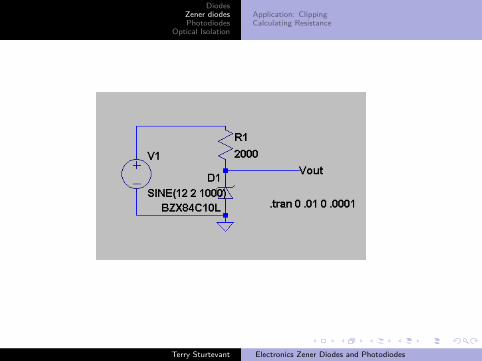
Here’s a Zener diode circuit simulation drawing.
Terry Sturtevant Electronics Zener Diodes and Photodiodes
DiodesZener diodesPhotodiodes
Optical Isolation
Application: ClippingCalculating Resistance
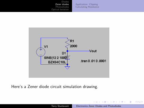
Here’s a Zener diode circuit simulation drawing.
Terry Sturtevant Electronics Zener Diodes and Photodiodes

DiodesZener diodesPhotodiodes
Optical Isolation
Application: ClippingCalculating Resistance
Terry Sturtevant Electronics Zener Diodes and Photodiodes
DiodesZener diodesPhotodiodes
Optical Isolation
Application: ClippingCalculating Resistance
Vin
Terry Sturtevant Electronics Zener Diodes and Photodiodes
DiodesZener diodesPhotodiodes
Optical Isolation
Application: ClippingCalculating Resistance
Vin Vout
Terry Sturtevant Electronics Zener Diodes and Photodiodes

DiodesZener diodesPhotodiodes
Optical Isolation
Application: ClippingCalculating Resistance
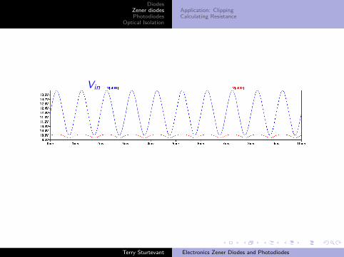
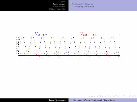
Vin Vout
For a 10V Zener diode, the output voltage range is much less thanthe input range.
Terry Sturtevant Electronics Zener Diodes and Photodiodes
DiodesZener diodesPhotodiodes
Optical Isolation
Application: ClippingCalculating Resistance
Vin Vout
Terry Sturtevant Electronics Zener Diodes and Photodiodes
DiodesZener diodesPhotodiodes
Optical Isolation
Application: ClippingCalculating Resistance
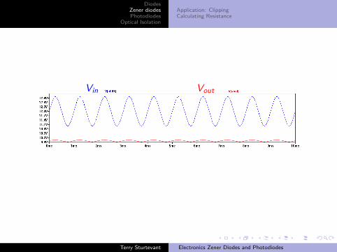
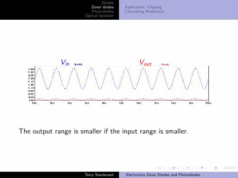
Vin Vout
The output range is smaller if the input range is smaller.
Terry Sturtevant Electronics Zener Diodes and Photodiodes

DiodesZener diodesPhotodiodes
Optical Isolation
Application: ClippingCalculating Resistance
Application: Clipping
Often it’s necessary to ensure that a signal does not exceed acertain voltage in order to avoid harming circuitry whichfollows.Again, using the car sensor example, a sensor inside theengine of a car may pick up electrical noise of hundreds ofvolts occasionally which could destroy a microprocessor.To avoid this, the signal may be clipped so that it never goesabove a fixed voltage.This can be done using a Zener diode.
Terry Sturtevant Electronics Zener Diodes and Photodiodes
DiodesZener diodesPhotodiodes
Optical Isolation
Application: ClippingCalculating Resistance
Application: Clipping
Often it’s necessary to ensure that a signal does not exceed acertain voltage in order to avoid harming circuitry whichfollows.
Again, using the car sensor example, a sensor inside theengine of a car may pick up electrical noise of hundreds ofvolts occasionally which could destroy a microprocessor.To avoid this, the signal may be clipped so that it never goesabove a fixed voltage.This can be done using a Zener diode.
Terry Sturtevant Electronics Zener Diodes and Photodiodes

DiodesZener diodesPhotodiodes
Optical Isolation
Application: ClippingCalculating Resistance
Application: Clipping
Often it’s necessary to ensure that a signal does not exceed acertain voltage in order to avoid harming circuitry whichfollows.Again, using the car sensor example, a sensor inside theengine of a car may pick up electrical noise of hundreds ofvolts occasionally which could destroy a microprocessor.
To avoid this, the signal may be clipped so that it never goesabove a fixed voltage.This can be done using a Zener diode.
Terry Sturtevant Electronics Zener Diodes and Photodiodes
DiodesZener diodesPhotodiodes
Optical Isolation
Application: ClippingCalculating Resistance
Application: Clipping
Often it’s necessary to ensure that a signal does not exceed acertain voltage in order to avoid harming circuitry whichfollows.Again, using the car sensor example, a sensor inside theengine of a car may pick up electrical noise of hundreds ofvolts occasionally which could destroy a microprocessor.To avoid this, the signal may be clipped so that it never goesabove a fixed voltage.
This can be done using a Zener diode.
Terry Sturtevant Electronics Zener Diodes and Photodiodes

DiodesZener diodesPhotodiodes
Optical Isolation
Application: ClippingCalculating Resistance
Application: Clipping
Often it’s necessary to ensure that a signal does not exceed acertain voltage in order to avoid harming circuitry whichfollows.Again, using the car sensor example, a sensor inside theengine of a car may pick up electrical noise of hundreds ofvolts occasionally which could destroy a microprocessor.To avoid this, the signal may be clipped so that it never goesabove a fixed voltage.This can be done using a Zener diode.
Terry Sturtevant Electronics Zener Diodes and Photodiodes

DiodesZener diodesPhotodiodes
Optical Isolation
Application: ClippingCalculating Resistance
Clipping a signal
Terry Sturtevant Electronics Zener Diodes and Photodiodes

DiodesZener diodesPhotodiodes
Optical Isolation
Application: ClippingCalculating Resistance
Vi
RzVo
Terry Sturtevant Electronics Zener Diodes and Photodiodes

DiodesZener diodesPhotodiodes
Optical Isolation
Application: ClippingCalculating Resistance
Calculating Resistance
Three parameters are needed to calculate the requiredresistance for a Zener diode:
1 supply voltage, VS2 Zener voltage, VZ3 recommended Zener current, I
The ideal value for the resistance, R, is given by:
R = VS − VZI
Terry Sturtevant Electronics Zener Diodes and Photodiodes

DiodesZener diodesPhotodiodes
Optical Isolation
Application: ClippingCalculating Resistance
Calculating Resistance
Three parameters are needed to calculate the requiredresistance for a Zener diode:
1 supply voltage, VS
2 Zener voltage, VZ3 recommended Zener current, I
The ideal value for the resistance, R, is given by:
R = VS − VZI
Terry Sturtevant Electronics Zener Diodes and Photodiodes
DiodesZener diodesPhotodiodes
Optical Isolation
Application: ClippingCalculating Resistance
Calculating Resistance
Three parameters are needed to calculate the requiredresistance for a Zener diode:
1 supply voltage, VS2 Zener voltage, VZ
3 recommended Zener current, IThe ideal value for the resistance, R, is given by:
R = VS − VZI
Terry Sturtevant Electronics Zener Diodes and Photodiodes

DiodesZener diodesPhotodiodes
Optical Isolation
Application: ClippingCalculating Resistance
Calculating Resistance
Three parameters are needed to calculate the requiredresistance for a Zener diode:
1 supply voltage, VS2 Zener voltage, VZ3 recommended Zener current, I
The ideal value for the resistance, R, is given by:
R = VS − VZI
Terry Sturtevant Electronics Zener Diodes and Photodiodes
DiodesZener diodesPhotodiodes
Optical IsolationCalculating Resistance
Photodiodes
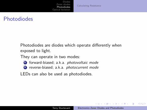
Photodiodes are diodes which operate differently whenexposed to light.They can operate in two modes:
1 forward-biased; a.k.a. photovoltaic mode2 reverse-biased; a.k.a. photocurrent mode
LEDs can also be used as photodiodes.
Terry Sturtevant Electronics Zener Diodes and Photodiodes
DiodesZener diodesPhotodiodes
Optical IsolationCalculating Resistance
Photodiodes
Photodiodes are diodes which operate differently whenexposed to light.
They can operate in two modes:1 forward-biased; a.k.a. photovoltaic mode2 reverse-biased; a.k.a. photocurrent mode
LEDs can also be used as photodiodes.
Terry Sturtevant Electronics Zener Diodes and Photodiodes

DiodesZener diodesPhotodiodes
Optical IsolationCalculating Resistance
Photodiodes
Photodiodes are diodes which operate differently whenexposed to light.They can operate in two modes:
1 forward-biased; a.k.a. photovoltaic mode2 reverse-biased; a.k.a. photocurrent mode
LEDs can also be used as photodiodes.
Terry Sturtevant Electronics Zener Diodes and Photodiodes

DiodesZener diodesPhotodiodes
Optical IsolationCalculating Resistance
Photodiodes
Photodiodes are diodes which operate differently whenexposed to light.They can operate in two modes:
1 forward-biased; a.k.a. photovoltaic mode
2 reverse-biased; a.k.a. photocurrent modeLEDs can also be used as photodiodes.
Terry Sturtevant Electronics Zener Diodes and Photodiodes

DiodesZener diodesPhotodiodes
Optical IsolationCalculating Resistance
Photodiodes
Photodiodes are diodes which operate differently whenexposed to light.They can operate in two modes:
1 forward-biased; a.k.a. photovoltaic mode2 reverse-biased; a.k.a. photocurrent mode
LEDs can also be used as photodiodes.
Terry Sturtevant Electronics Zener Diodes and Photodiodes

DiodesZener diodesPhotodiodes
Optical IsolationCalculating Resistance
Photodiode symbol
Terry Sturtevant Electronics Zener Diodes and Photodiodes
DiodesZener diodesPhotodiodes
Optical IsolationCalculating Resistance
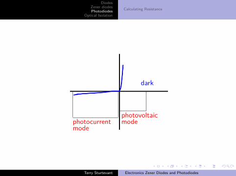
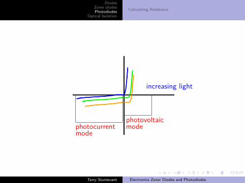
photocurrentmode
photovoltaicmode
dark
Terry Sturtevant Electronics Zener Diodes and Photodiodes

DiodesZener diodesPhotodiodes
Optical IsolationCalculating Resistance
photocurrentmode
photovoltaicmode
increasing light
Terry Sturtevant Electronics Zener Diodes and Photodiodes
DiodesZener diodesPhotodiodes
Optical IsolationCalculating Resistance
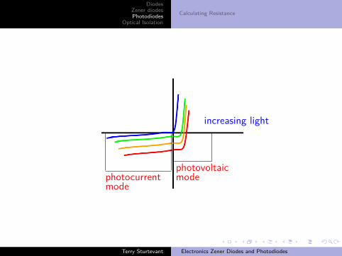
photocurrentmode
photovoltaicmode
increasing light
Terry Sturtevant Electronics Zener Diodes and Photodiodes
DiodesZener diodesPhotodiodes
Optical IsolationCalculating Resistance
photocurrentmode
photovoltaicmode
increasing light
Terry Sturtevant Electronics Zener Diodes and Photodiodes
DiodesZener diodesPhotodiodes
Optical IsolationCalculating Resistance
To use a photodiode in photovoltaic mode:
Measure the forward-biased voltage which changes with lightTo use a photodiode in photocurrent mode:Put it reverse-biased in a voltage divider like a Zener diodeand measure the reverse-biased voltage which changes withlight
Terry Sturtevant Electronics Zener Diodes and Photodiodes

DiodesZener diodesPhotodiodes
Optical IsolationCalculating Resistance
To use a photodiode in photovoltaic mode:Measure the forward-biased voltage which changes with light
To use a photodiode in photocurrent mode:Put it reverse-biased in a voltage divider like a Zener diodeand measure the reverse-biased voltage which changes withlight
Terry Sturtevant Electronics Zener Diodes and Photodiodes
DiodesZener diodesPhotodiodes
Optical IsolationCalculating Resistance
To use a photodiode in photovoltaic mode:Measure the forward-biased voltage which changes with lightTo use a photodiode in photocurrent mode:
Put it reverse-biased in a voltage divider like a Zener diodeand measure the reverse-biased voltage which changes withlight
Terry Sturtevant Electronics Zener Diodes and Photodiodes
DiodesZener diodesPhotodiodes
Optical IsolationCalculating Resistance
To use a photodiode in photovoltaic mode:Measure the forward-biased voltage which changes with lightTo use a photodiode in photocurrent mode:Put it reverse-biased in a voltage divider like a Zener diodeand measure the reverse-biased voltage which changes withlight
Terry Sturtevant Electronics Zener Diodes and Photodiodes
DiodesZener diodesPhotodiodes
Optical IsolationCalculating Resistance
Calculating Resistance
Three parameters are needed to calculate the requiredresistance for a photodiode:
1 supply voltage, VS2 photocurrent, Ip3 desired voltage change with light, Vo
The ideal value for the resistance, R, is given by:
R = VS − VoIp
Terry Sturtevant Electronics Zener Diodes and Photodiodes

DiodesZener diodesPhotodiodes
Optical IsolationCalculating Resistance
Calculating Resistance
Three parameters are needed to calculate the requiredresistance for a photodiode:
1 supply voltage, VS
2 photocurrent, Ip3 desired voltage change with light, Vo
The ideal value for the resistance, R, is given by:
R = VS − VoIp
Terry Sturtevant Electronics Zener Diodes and Photodiodes
DiodesZener diodesPhotodiodes
Optical IsolationCalculating Resistance
Calculating Resistance
Three parameters are needed to calculate the requiredresistance for a photodiode:
1 supply voltage, VS2 photocurrent, Ip
3 desired voltage change with light, Vo
The ideal value for the resistance, R, is given by:
R = VS − VoIp
Terry Sturtevant Electronics Zener Diodes and Photodiodes

DiodesZener diodesPhotodiodes
Optical IsolationCalculating Resistance
Calculating Resistance
Three parameters are needed to calculate the requiredresistance for a photodiode:
1 supply voltage, VS2 photocurrent, Ip3 desired voltage change with light, Vo
The ideal value for the resistance, R, is given by:
R = VS − VoIp
Terry Sturtevant Electronics Zener Diodes and Photodiodes

DiodesZener diodesPhotodiodes
Optical IsolationCalculating Resistance
Calculating Resistance
Three parameters are needed to calculate the requiredresistance for a photodiode:
1 supply voltage, VS2 photocurrent, Ip3 desired voltage change with light, Vo
The ideal value for the resistance, R, is given by:
R = VS − VoIp
Terry Sturtevant Electronics Zener Diodes and Photodiodes
DiodesZener diodesPhotodiodes
Optical Isolation
Optical Isolation
Optical isolation using an LED and a phototransistor orphotodiode
can transmit DC (i.e. steady-state values)only one waycannot transmit powerthe above two conditions mean that there is no danger ofvoltage spikes as there is with inductive isolation
Terry Sturtevant Electronics Zener Diodes and Photodiodes
DiodesZener diodesPhotodiodes
Optical Isolation
Optical Isolation
Optical isolation using an LED and a phototransistor orphotodiode
can transmit DC (i.e. steady-state values)
only one waycannot transmit powerthe above two conditions mean that there is no danger ofvoltage spikes as there is with inductive isolation
Terry Sturtevant Electronics Zener Diodes and Photodiodes
DiodesZener diodesPhotodiodes
Optical Isolation
Optical Isolation
Optical isolation using an LED and a phototransistor orphotodiode
can transmit DC (i.e. steady-state values)only one way
cannot transmit powerthe above two conditions mean that there is no danger ofvoltage spikes as there is with inductive isolation
Terry Sturtevant Electronics Zener Diodes and Photodiodes
DiodesZener diodesPhotodiodes
Optical Isolation
Optical Isolation
Optical isolation using an LED and a phototransistor orphotodiode
can transmit DC (i.e. steady-state values)only one waycannot transmit power
the above two conditions mean that there is no danger ofvoltage spikes as there is with inductive isolation
Terry Sturtevant Electronics Zener Diodes and Photodiodes
DiodesZener diodesPhotodiodes
Optical Isolation
Optical Isolation
Optical isolation using an LED and a phototransistor orphotodiode
can transmit DC (i.e. steady-state values)only one waycannot transmit powerthe above two conditions mean that there is no danger ofvoltage spikes as there is with inductive isolation
Terry Sturtevant Electronics Zener Diodes and Photodiodes

DiodesZener diodesPhotodiodes
Optical Isolation
The resistors are used because effectively the LED and thephototransistor are current devices, and usually signals areprocessed as voltages.
The values chosen for the resistors should be consistent withthe current specifications for the device.The amount of DC isolation provided by an optoisolator isusually in the range of kV.At some point the insulation will break down and arcs canoccur.
Terry Sturtevant Electronics Zener Diodes and Photodiodes
DiodesZener diodesPhotodiodes
Optical Isolation
The resistors are used because effectively the LED and thephototransistor are current devices, and usually signals areprocessed as voltages.The values chosen for the resistors should be consistent withthe current specifications for the device.
The amount of DC isolation provided by an optoisolator isusually in the range of kV.At some point the insulation will break down and arcs canoccur.
Terry Sturtevant Electronics Zener Diodes and Photodiodes

DiodesZener diodesPhotodiodes
Optical Isolation
The resistors are used because effectively the LED and thephototransistor are current devices, and usually signals areprocessed as voltages.The values chosen for the resistors should be consistent withthe current specifications for the device.The amount of DC isolation provided by an optoisolator isusually in the range of kV.
At some point the insulation will break down and arcs canoccur.
Terry Sturtevant Electronics Zener Diodes and Photodiodes

DiodesZener diodesPhotodiodes
Optical Isolation
The resistors are used because effectively the LED and thephototransistor are current devices, and usually signals areprocessed as voltages.The values chosen for the resistors should be consistent withthe current specifications for the device.The amount of DC isolation provided by an optoisolator isusually in the range of kV.At some point the insulation will break down and arcs canoccur.
Terry Sturtevant Electronics Zener Diodes and Photodiodes

DiodesZener diodesPhotodiodes
Optical Isolation
VsVi
Vo
Ri
Ro
Terry Sturtevant Electronics Zener Diodes and Photodiodes

DiodesZener diodesPhotodiodes
Optical Isolation
Whenever sensors are in a place where it is possible for highvoltages to be induced, optical isolation should be used to protectelectronic devices which follow.
Terry Sturtevant Electronics Zener Diodes and Photodiodes