Community supported agriculture... the story so far Kirstin Glendinning

Electronic Engine Controlsby Glendinning
Installation & Operation Manual v8.0A
(software version 8)
Glendinning Marine Products, Inc.740 Century CircleConway, SC 29526
(843) 399-6146Fax: (843) 399-5005
www.glendinningprods.com PRINT DATE: 11/06EEC1M_v8.0A

iTable of Contents
1.0 System Description & Capabilities . . . . . . . . . . . . . . . . . . . . . . . . . . . . . . . . . . . . . . . . . . . . . . . . . . . . . . . . . . . . .11.1 Control Head . . . . . . . . . . . . . . . . . . . . . . . . . . . . . . . . . . . . . . . . . . . . . . . . . . . . . . . . . . . . . . . . . . . . . .21.2 Engine Processor (EP) . . . . . . . . . . . . . . . . . . . . . . . . . . . . . . . . . . . . . . . . . . . . . . . . . . . . . . . . . . . . . .31.3 Actuator . . . . . . . . . . . . . . . . . . . . . . . . . . . . . . . . . . . . . . . . . . . . . . . . . . . . . . . . . . . . . . . . . . . . . . . . . .41.4 Integrated Mechanical Backup Assembly . . . . . . . . . . . . . . . . . . . . . . . . . . . . . . . . . . . . . . . . . . . . . . . .51.5 Station Processor . . . . . . . . . . . . . . . . . . . . . . . . . . . . . . . . . . . . . . . . . . . . . . . . . . . . . . . . . . . . . . . . . .61.6 Tachometer Senders . . . . . . . . . . . . . . . . . . . . . . . . . . . . . . . . . . . . . . . . . . . . . . . . . . . . . . . . . . . . . . . .6
2.0 Operating the EEC System . . . . . . . . . . . . . . . . . . . . . . . . . . . . . . . . . . . . . . . . . . . . . . . . . . . . . . . . . . . . . . . . . . . . . .92.1 General Information . . . . . . . . . . . . . . . . . . . . . . . . . . . . . . . . . . . . . . . . . . . . . . . . . . . . . . . . . . . . . . . . .92.2 Control System Startup . . . . . . . . . . . . . . . . . . . . . . . . . . . . . . . . . . . . . . . . . . . . . . . . . . . . . . . . . . . . .132.3 Cruise Mode . . . . . . . . . . . . . . . . . . . . . . . . . . . . . . . . . . . . . . . . . . . . . . . . . . . . . . . . . . . . . . . . . . . . .142.4 Sync Mode . . . . . . . . . . . . . . . . . . . . . . . . . . . . . . . . . . . . . . . . . . . . . . . . . . . . . . . . . . . . . . . . . . . . . . .172.5 Warm Mode . . . . . . . . . . . . . . . . . . . . . . . . . . . . . . . . . . . . . . . . . . . . . . . . . . . . . . . . . . . . . . . . . . . . . .192.6 Slow Mode . . . . . . . . . . . . . . . . . . . . . . . . . . . . . . . . . . . . . . . . . . . . . . . . . . . . . . . . . . . . . . . . . . . . . . .202.7 Troll Mode . . . . . . . . . . . . . . . . . . . . . . . . . . . . . . . . . . . . . . . . . . . . . . . . . . . . . . . . . . . . . . . . . . . . . . .212.8 Station Transfer . . . . . . . . . . . . . . . . . . . . . . . . . . . . . . . . . . . . . . . . . . . . . . . . . . . . . . . . . . . . . . . . . . .222.9 Alarm Mode / Mechanical Backup Operation . . . . . . . . . . . . . . . . . . . . . . . . . . . . . . . . . . . . . . . . . . . .24
3.0 Installing the EEC System . . . . . . . . . . . . . . . . . . . . . . . . . . . . . . . . . . . . . . . . . . . . . . . . . . . . . . . . . . . . . . . . . . . . .293.1 Pre-Installation Planning . . . . . . . . . . . . . . . . . . . . . . . . . . . . . . . . . . . . . . . . . . . . . . . . . . . . . . . . . . . .293.2 Cable Connections . . . . . . . . . . . . . . . . . . . . . . . . . . . . . . . . . . . . . . . . . . . . . . . . . . . . . . . . . . . . . . . .363.3 Engine Room Component Installation . . . . . . . . . . . . . . . . . . . . . . . . . . . . . . . . . . . . . . . . . . . . . . . . . .373.4 Engine Room Electrical Connections . . . . . . . . . . . . . . . . . . . . . . . . . . . . . . . . . . . . . . . . . . . . . . . . . .473.5 Topside Component Installation . . . . . . . . . . . . . . . . . . . . . . . . . . . . . . . . . . . . . . . . . . . . . . . . . . . . . .52
4.0 Maintenance . . . . . . . . . . . . . . . . . . . . . . . . . . . . . . . . . . . . . . . . . . . . . . . . . . . . . . . . . . . . . . . . . . . . . . . . . . . . . . . . . . .614.1 Routine Maintenance . . . . . . . . . . . . . . . . . . . . . . . . . . . . . . . . . . . . . . . . . . . . . . . . . . . . . . . . . . . . . . .614.2 System Calibration Check . . . . . . . . . . . . . . . . . . . . . . . . . . . . . . . . . . . . . . . . . . . . . . . . . . . . . . . . . . .614.3 Actuator Control Cable Replacement . . . . . . . . . . . . . . . . . . . . . . . . . . . . . . . . . . . . . . . . . . . . . . . . . .62
5.0 System Configuration . . . . . . . . . . . . . . . . . . . . . . . . . . . . . . . . . . . . . . . . . . . . . . . . . . . . . . . . . . . . . . . . . . . . . . . . .655.1 System Preparation . . . . . . . . . . . . . . . . . . . . . . . . . . . . . . . . . . . . . . . . . . . . . . . . . . . . . . . . . . . . . . . .655.2 Entering Calibration Mode . . . . . . . . . . . . . . . . . . . . . . . . . . . . . . . . . . . . . . . . . . . . . . . . . . . . . . . . . . .695.3 Actuator Positioning . . . . . . . . . . . . . . . . . . . . . . . . . . . . . . . . . . . . . . . . . . . . . . . . . . . . . . . . . . . . . . . .705.4 Exiting Calibration Mode . . . . . . . . . . . . . . . . . . . . . . . . . . . . . . . . . . . . . . . . . . . . . . . . . . . . . . . . . . . .735.5 Calibration Verification . . . . . . . . . . . . . . . . . . . . . . . . . . . . . . . . . . . . . . . . . . . . . . . . . . . . . . . . . . . . . .74
6.0 System Test & Checkout . . . . . . . . . . . . . . . . . . . . . . . . . . . . . . . . . . . . . . . . . . . . . . . . . . . . . . . . . . . . . . . . . . . . . . .776.1 Component Installation Checks . . . . . . . . . . . . . . . . . . . . . . . . . . . . . . . . . . . . . . . . . . . . . . . . . . . . . . .776.2 Operational Checks . . . . . . . . . . . . . . . . . . . . . . . . . . . . . . . . . . . . . . . . . . . . . . . . . . . . . . . . . . . . . . . .796.3 System Inspection / Checkout . . . . . . . . . . . . . . . . . . . . . . . . . . . . . . . . . . . . . . . . . . . . . . . . . . . . . . . .79
7.0 Troubleshooting . . . . . . . . . . . . . . . . . . . . . . . . . . . . . . . . . . . . . . . . . . . . . . . . . . . . . . . . . . . . . . . . . . . . . . . . . . . . . . .857.1 Troubleshoot Mode (Recover Alarm History) . . . . . . . . . . . . . . . . . . . . . . . . . . . . . . . . . . . . . . . . . . . .877.2 Alarm Code Recovery from the Control Head . . . . . . . . . . . . . . . . . . . . . . . . . . . . . . . . . . . . . . . . . . .897.3 Troubleshooting Chart . . . . . . . . . . . . . . . . . . . . . . . . . . . . . . . . . . . . . . . . . . . . . . . . . . . . . . . . . . . . . .97
8.0 Appendix / References . . . . . . . . . . . . . . . . . . . . . . . . . . . . . . . . . . . . . . . . . . . . . . . . . . . . . . . . . . . . . . . . . . . . . . .101A. Wiring Diagram . . . . . . . . . . . . . . . . . . . . . . . . . . . . . . . . . . . . . . . . . . . . . . . . . . . . . . . . . . . . . . . . . .102B. Engine Processor Dimensions . . . . . . . . . . . . . . . . . . . . . . . . . . . . . . . . . . . . . . . . . . . . . . . . . . . . . .103C. Actuator Dimensions . . . . . . . . . . . . . . . . . . . . . . . . . . . . . . . . . . . . . . . . . . . . . . . . . . . . . . . . . . . . . .104D. Station Processor Dimensions . . . . . . . . . . . . . . . . . . . . . . . . . . . . . . . . . . . . . . . . . . . . . . . . . . . . . .105
Chapters at a Glance

ii EEC System Manual
E. Control Head Mechanical Backup Dimensions . . . . . . . . . . . . . . . . . . . . . . . . . . . . . . . . . . . . . . . . . .106F. Control Head Remote (Electric Only) Dimensions . . . . . . . . . . . . . . . . . . . . . . . . . . . . . . . . . . . . . . .107G. New Style Topmount Control Head Dimensions . . . . . . . . . . . . . . . . . . . . . . . . . . . . . . . . . . . . . . . . .108H. Sidemount Control Head Installation . . . . . . . . . . . . . . . . . . . . . . . . . . . . . . . . . . . . . . . . . . . . . . . . . .109I. Control Head Template - New Style . . . . . . . . . . . . . . . . . . . . . . . . . . . . . . . . . . . . . . . . . . . . . . . . . . .111J. Sidemount Wiring Diagram . . . . . . . . . . . . . . . . . . . . . . . . . . . . . . . . . . . . . . . . . . . . . . . . . . . . . . . . .112K. Sidemount Keypad Assembly Template . . . . . . . . . . . . . . . . . . . . . . . . . . . . . . . . . . . . . . . . . . . . . . .113
8.1 Custom Configuration Options . . . . . . . . . . . . . . . . . . . . . . . . . . . . . . . . . . . . . . . . . . . . . . . . . . . . . .115A. Control Station Custom Options . . . . . . . . . . . . . . . . . . . . . . . . . . . . . . . . . . . . . . . . . . . . . . . . .116B. Gear Custom Options . . . . . . . . . . . . . . . . . . . . . . . . . . . . . . . . . . . . . . . . . . . . . . . . . . . . . . . . .117C. Throttle Custom Options . . . . . . . . . . . . . . . . . . . . . . . . . . . . . . . . . . . . . . . . . . . . . . . . . . . . . . .121D. Troll Custom Options . . . . . . . . . . . . . . . . . . . . . . . . . . . . . . . . . . . . . . . . . . . . . . . . . . . . . . . . . .122E. Other Custom Options . . . . . . . . . . . . . . . . . . . . . . . . . . . . . . . . . . . . . . . . . . . . . . . . . . . . . . . . .126
A word about the Symbols used in the ManualWhen driving from one destination to another, road signs prove to be invaluable. Road signs are an important source ofinformation. For example, road signs can warn you about potential problems ahead to help divert certain disaster or theycan let you know where to turn off for a rest or a meal.
In an effort to help you navigate your way through this manual we will from time to time use the following symbols:
Throughout the manual the NOTES symbol will appear to support what has been mentioned in the text. Anote can be used where further explanation is needed or where something needs highlighting. BE CAREFULto read all NOTES.
Sometimes it is helpful to take a break and really absorb what you just read. The WARNING symbol will alertthe reader to information that needs to be completely understood before you continue on in the reading of themanual. ALWAYS STOP and READ these points.
The TIP symbol will be used when something mentioned in the text need more “light” shed on it. The tip couldexplain or be a list of do’s and don’ts. Whatever the TIP is, you do not want to miss out on the information itcontains.
MANUAL REVISIONS REVISION PAGE # DESCRIPTION DATE of CHANGE
8.0 -- Initial start-up of document AUGUST 2005
8.0a 68 Corrected configuration steps for TROLL. NOVEMBER 2006
1Section 1.0 — System Description & Capabilities
1.0 System Description & CapabilitiesThe Electronic Engine Control System (EEC) has been designed by Glendinning Marine Productsas an alternative to other means of controlling a marine propulsion system, such as mechanical,hydraulic, or pneumatic controls. By means of sophisticated, state of the art electronics and digi-tal computer programming, the boat owner can now have the ability to control his engines andreverse gear with more precision and less effort than ever before. In addition, a number of fea-tures not offered with any other type of control system are now available.
The Glendinning Electronic Engine Control incorporates the following significant features:
• Convenient "single-lever" electronic control — Electronic control permits theuse of single lever operation-combined clutch and throttle in one handle-from up to6 stations, without the "stiffness" normally encountered with mechanical or hydrauliccontrols.
• Mechanical Backup — Mechanical control for use in the event of system failure,such as loss of DC power. This mechanical backup system utilizes a separate con-trol head, or in some cases the same head used to control the boat electronically.
• Sophisticated Power Management — Power system designed to receive powerfrom two independent power sources.
• Extremely Accurate Synchronization — Synchronization capability similar to thatof the Glendinning mechanical Automatic Synchronizer (accurate to about 5 RPMdifferential throughout the RPM range).
• Solid Construction — Rugged, robust construction, comparable to other productsmanufactured by Glendinning Marine Products. All system components are com-pletely sealed from the environment.
• Complete Electrical Shielding — The system is completely shielded to eliminateproblems caused by electromagnetic interference, complying with the latest andstrictest standards in the industry.
In its most general form, the Electronic Engine Control system consists of four separate compo-nents:
Control Head — The Control Head is the means by which the boat operator commands the EECsystem. .
Engine Processor — The Engine Processor is the heart of the system and controls operation ofall the other components.
2 EEC System Manual
Actuators — The actuators move the governor/throttle lever, gearbox lever, and /or troll valve controllevers and are controlled by the Engine Processor
Mechanical Backup (optional) — One Control Head is connected to the Actuators via mechanicalpush-pull cables. In the event that DC power is lost or if the system were to fail, these cables allow theboat operator to bypass the entire EEC system and control the engine throttle and gearbox directly.
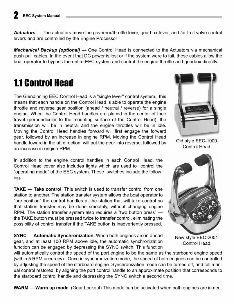
1.1 Control HeadThe Glendinning EEC Control Head is a "single lever" control system, thismeans that each handle on the Control Head is able to operate the enginethrottle and reverse gear position (ahead / neutral / reverse) for a singleengine. When the Control Head handles are placed in the center of theirtravel (perpendicular to the mounting surface of the Control Head), thetransmission will be in neutral and the engine throttles will be in idle.Moving the Control Head handles forward will first engage the forwardgear, followed by an increase in engine RPM. Moving the Control Headhandle toward in the aft direction, will put the gear into reverse, followed byan increase in engine RPM.
In addition to the engine control handles in each Control Head, theControl Head cover also includes lights which are used to control the"operating mode" of the EEC system. These switches include the follow-ing:
TAKE — Take control. This switch is used to transfer control from onestation to another. The station transfer system allows the boat operator to"pre-position" the control handles at the station that will take control sothat station transfer may be done smoothly, without changing engineRPM. The station transfer system also requires a "two button press” —the TAKE button must be pressed twice to transfer control, eliminating thepossibility of control transfer if the TAKE button is inadvertently pressed.
SYNC — Automatic Synchronization. When both engines are in aheadgear, and at least 100 RPM above idle, the automatic synchronizationfunction can be engaged by depressing the SYNC switch. This functionwill automatically control the speed of the port engine to be the same as the starboard engine speed(within 5 RPM accuracy). Once in synchronization mode, the speed of both engines can be controlledby adjusting the speed of the starboard engine. Synchronization mode can be turned off, and full man-ual control restored, by aligning the port control handle to an approximate position that corresponds tothe starboard control handle and depressing the SYNC switch a second time.
WARM — Warm up mode. (Gear Lockout) This mode can be activated when both engines are in neu-
Old style EEC-1000Control Head
New style EEC-2001Control Head
Section 1.0 — System Description & Capabilities
tral. Once activated, by depressing the WARM button, the control lever handle can be advanced intothe ahead throttle position in order to accelerate the engine speed while leaving the gear in neutral.The system will remain in the warm up mode until the handle is returned to Neutral and the WARM but-ton is depressed a second time.
TROLL — Troll mode. This switch can be used to operate the trolling valves for boats so equipped.While in Troll Mode, the boat operator is able to control the gear position (Ahead, Reverse, andNeutral) and the trolling valve position (Full slip to no slip). To prevent transmission damage, the enginethrottle will remain in idle at any time that the troll valve is not in the Full Lockup - no slip - position.(While in normal Cruise Mode, the trolling valve actuator is always in the Full Lockup - no slip - posi-tion). Troll Mode is activated from Neutral by depressing the TROLL button on the keypad once.
SLOW — Slow mode. The "slow" mode changes the range of handle movement from 0 - 100% enginespeed to approximately 0 - 50%. (That is, full handle travel will only give you about one-half of WOTengine speed). This will provide the boat owner with a much greater control of engine RPM at slowcruise speeds and in close quarters maneuvers such as docking. Slow Mode is activated by depress-ing the TAKE and TROLL buttons simultaneously.
Indicator lights clearly signal the boat operator of the status of the control system and what operatingmode the EEC system is in. A buzzer is also installed to signal system problems, such as low batteryinput voltage.
The Control Head is sealed from the external environment and is normally mounted on top of a flat sur-face. A single station communication cable, which exits from the bottom of the control head assembly,connects the control handle to the Engine Processor. The connector cable is factory terminated with awaterproof, electrically shielded end connector. The Control Head is approximately the same size asother control heads available in the industry. In addition to the "topmount" control head that is shownin the photograph (opposite page), a "sidemount" control head is also available for boats equipped with"Palm Beach" style controls. When a sidemount control is used, the operating mode control switchesare mounted in a control keypad assembly which may be located remotely, anywhere at the helm sta-tion.
1.2 Engine Processor (EP)The engine processor is the hub of the EEC system and could be considered its "brain" (central pro-cessing unit). The Engine Processor performs the following functions:
� The primary function of the engine processor is to receive commands from the control
3
For boats that are equipped with troll valves, the troll valve operating mode may be selected in one of three
ways: redesignate the "Slow" mode switch to activate "Troll" mode, use a combination of the "Take", and
"Slow" buttons pressed at the same time, or use a button / indicator light separate from the control head.
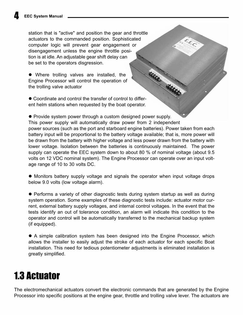
station that is "active" and position the gear and throttleactuators to the commanded position. Sophisticatedcomputer logic will prevent gear engagement ordisengagement unless the engine throttle posi-tion is at idle. An adjustable gear shift delay canbe set to the operators disgression.
� Where trolling valves are installed, theEngine Processor will control the operation ofthe trolling valve actuator
� Coordinate and control the transfer of control to differ-ent helm stations when requested by the boat operator.
� Provide system power through a custom designed power supply.This power supply will automatically draw power from 2 independentpower sources (such as the port and starboard engine batteries). Power taken from eachbattery input will be proportional to the battery voltage available; that is, more power willbe drawn from the battery with higher voltage and less power drawn from the battery withlower voltage. Isolation between the batteries is continuously maintained. The powersupply can operate the EEC system down to about 80 % of nominal voltage (about 9.5volts on 12 VDC nominal system). The Engine Processor can operate over an input volt-age range of 10 to 30 volts DC.
� Monitors battery supply voltage and signals the operator when input voltage dropsbelow 9.0 volts (low voltage alarm).
� Performs a variety of other diagnostic tests during system startup as well as duringsystem operation. Some examples of these diagnostic tests include: actuator motor cur-rent, external battery supply voltages, and internal control voltages. In the event that thetests identify an out of tolerance condition, an alarm will indicate this condition to theoperator and control will be automatically transferred to the mechanical backup system(if equipped).
� A simple calibration system has been designed into the Engine Processor, whichallows the installer to easily adjust the stroke of each actuator for each specific Boatinstallation. This need for tedious potentiometer adjustments is eliminated installation isgreatly simplified.
1.3 ActuatorThe electromechanical actuators convert the electronic commands that are generated by the EngineProcessor into specific positions at the engine gear, throttle and trolling valve lever. The actuators are
EEC System Manual4
Section 1.0 — System Description & Capabilities
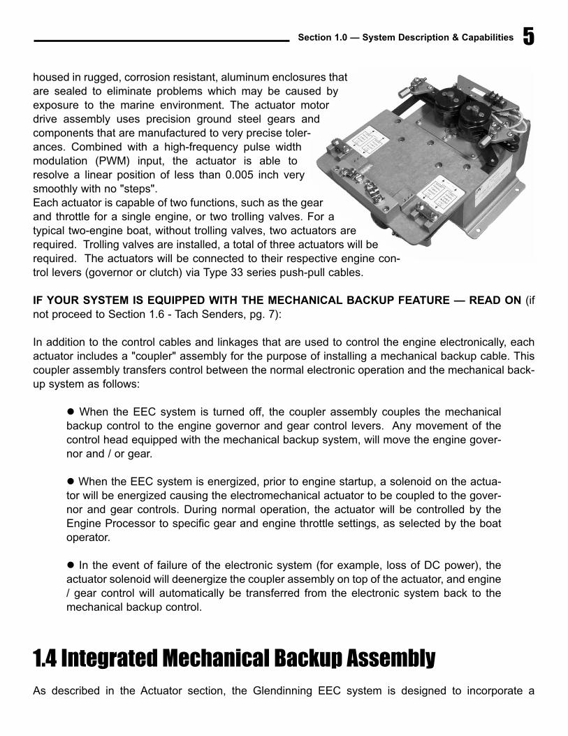
housed in rugged, corrosion resistant, aluminum enclosures thatare sealed to eliminate problems which may be caused byexposure to the marine environment. The actuator motordrive assembly uses precision ground steel gears andcomponents that are manufactured to very precise toler-ances. Combined with a high-frequency pulse widthmodulation (PWM) input, the actuator is able toresolve a linear position of less than 0.005 inch verysmoothly with no "steps". Each actuator is capable of two functions, such as the gearand throttle for a single engine, or two trolling valves. For atypical two-engine boat, without trolling valves, two actuators arerequired. Trolling valves are installed, a total of three actuators will berequired. The actuators will be connected to their respective engine con-trol levers (governor or clutch) via Type 33 series push-pull cables.
IF YOUR SYSTEM IS EQUIPPED WITH THE MECHANICAL BACKUP FEATURE — READ ON (ifnot proceed to Section 1.6 - Tach Senders, pg. 7):
In addition to the control cables and linkages that are used to control the engine electronically, eachactuator includes a "coupler" assembly for the purpose of installing a mechanical backup cable. Thiscoupler assembly transfers control between the normal electronic operation and the mechanical back-up system as follows:
� When the EEC system is turned off, the coupler assembly couples the mechanicalbackup control to the engine governor and gear control levers. Any movement of thecontrol head equipped with the mechanical backup system, will move the engine gover-nor and / or gear.
� When the EEC system is energized, prior to engine startup, a solenoid on the actua-tor will be energized causing the electromechanical actuator to be coupled to the gover-nor and gear controls. During normal operation, the actuator will be controlled by theEngine Processor to specific gear and engine throttle settings, as selected by the boatoperator.
� In the event of failure of the electronic system (for example, loss of DC power), theactuator solenoid will deenergize the coupler assembly on top of the actuator, and engine/ gear control will automatically be transferred from the electronic system back to themechanical backup control.
1.4 Integrated Mechanical Backup AssemblyAs described in the Actuator section, the Glendinning EEC system is designed to incorporate a
5
EEC System Manual6
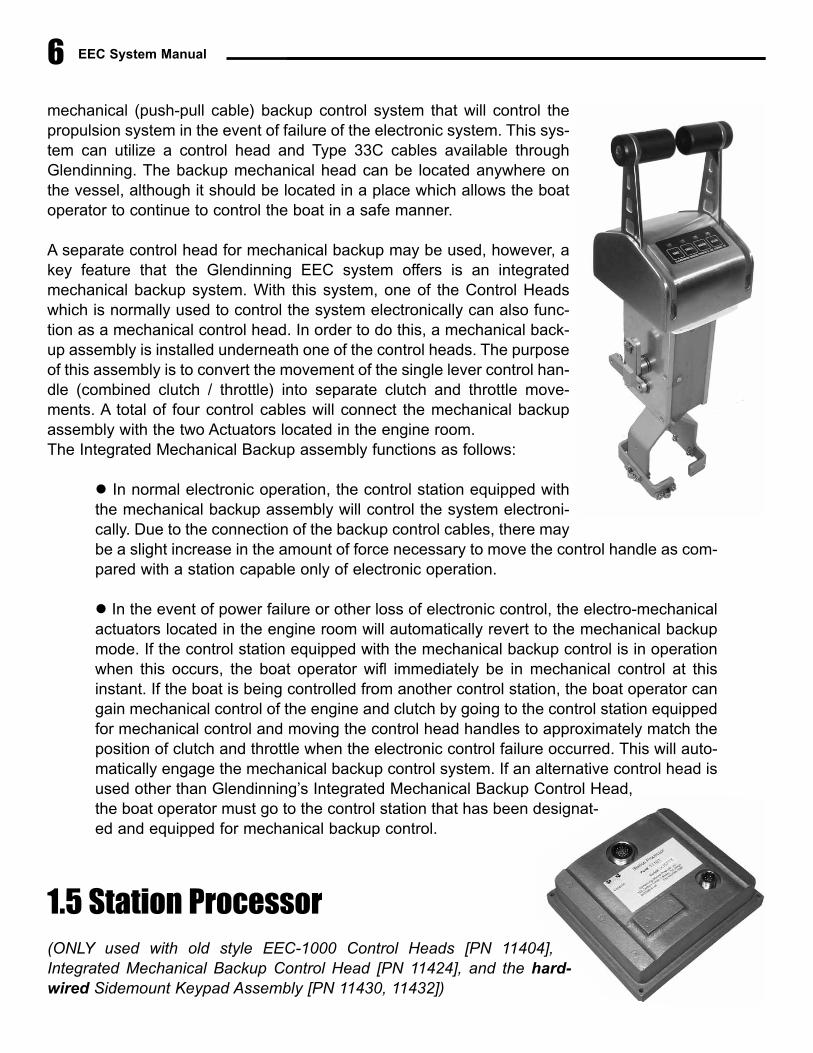
mechanical (push-pull cable) backup control system that will control thepropulsion system in the event of failure of the electronic system. This sys-tem can utilize a control head and Type 33C cables available throughGlendinning. The backup mechanical head can be located anywhere onthe vessel, although it should be located in a place which allows the boatoperator to continue to control the boat in a safe manner.
A separate control head for mechanical backup may be used, however, akey feature that the Glendinning EEC system offers is an integratedmechanical backup system. With this system, one of the Control Headswhich is normally used to control the system electronically can also func-tion as a mechanical control head. In order to do this, a mechanical back-up assembly is installed underneath one of the control heads. The purposeof this assembly is to convert the movement of the single lever control han-dle (combined clutch / throttle) into separate clutch and throttle move-ments. A total of four control cables will connect the mechanical backupassembly with the two Actuators located in the engine room. The Integrated Mechanical Backup assembly functions as follows:
� In normal electronic operation, the control station equipped withthe mechanical backup assembly will control the system electroni-cally. Due to the connection of the backup control cables, there maybe a slight increase in the amount of force necessary to move the control handle as com-pared with a station capable only of electronic operation.
� In the event of power failure or other loss of electronic control, the electro-mechanicalactuators located in the engine room will automatically revert to the mechanical backupmode. If the control station equipped with the mechanical backup control is in operationwhen this occurs, the boat operator wifl immediately be in mechanical control at thisinstant. If the boat is being controlled from another control station, the boat operator cangain mechanical control of the engine and clutch by going to the control station equippedfor mechanical control and moving the control head handles to approximately match theposition of clutch and throttle when the electronic control failure occurred. This will auto-matically engage the mechanical backup control system. If an alternative control head isused other than Glendinning’s Integrated Mechanical Backup Control Head,the boat operator must go to the control station that has been designat-ed and equipped for mechanical backup control.
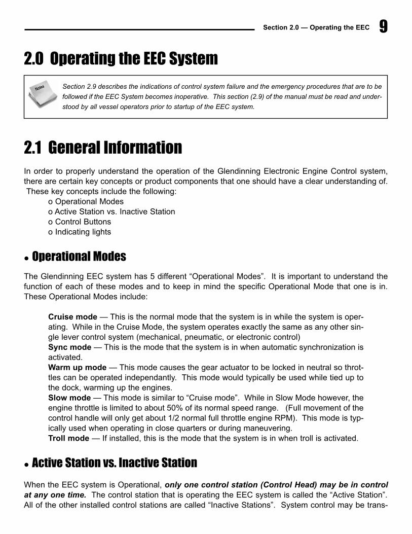
1.5 Station Processor (ONLY used with old style EEC-1000 Control Heads [PN 11404],Integrated Mechanical Backup Control Head [PN 11424], and the hard-wired Sidemount Keypad Assembly [PN 11430, 11432])

Section 1.0 — System Description & Capabilities
The Station Processor is located within a few feet of the Control Head, and is electrically connected tothe Engine Processor. The function of the station processor is to interface between the Control Headand the Engine Processor. In brief, the station processor will analyze the position of the Control Headhandles and the operating mode buttons and sends this information to the engine processor via a cus-tom designed digital communications link.
1.6 Tachometer SendersIn order to accurately synchronize the engines to a 5 RPM max-imum difierential, the Engine Processor requires very accurateengine RPM information. This information is supplied to theEngine Processor using tachometer senders. One tach sendermust be mounted on each engine, typically using the mechanicaltachometer outlet provided on the engine. Where a mechanicaltachometer outlet connection is not available on the engine,mechanical drive adapters can be installed to provide this con-nection. The tach senders can also be used to provide RPM infor-mation to the digital tachometer heads or other compatibletachometer indicators.
7

EEC System Manual8
Section 2.0 — Operating the EEC 9
2.0 Operating the EEC System
2.1 General InformationIn order to properly understand the operation of the Glendinning Electronic Engine Control system,there are certain key concepts or product components that one should have a clear understanding of.These key concepts include the following:
o Operational Modeso Active Station vs. Inactive Stationo Control Buttonso Indicating lights
� Operational Modes
The Glendinning EEC system has 5 different “Operational Modes”. It is important to understand thefunction of each of these modes and to keep in mind the specific Operational Mode that one is in.These Operational Modes include:
Cruise mode — This is the normal mode that the system is in while the system is oper-ating. While in the Cruise Mode, the system operates exactly the same as any other sin-gle lever control system (mechanical, pneumatic, or electronic control)Sync mode — This is the mode that the system is in when automatic synchronization isactivated.Warm up mode — This mode causes the gear actuator to be locked in neutral so throt-tles can be operated independantly. This mode would typically be used while tied up tothe dock, warming up the engines.Slow mode — This mode is similar to “Cruise mode”. While in Slow Mode however, theengine throttle is limited to about 50% of its normal speed range. (Full movement of thecontrol handle will only get about 1/2 normal full throttle engine RPM). This mode is typ-ically used when operating in close quarters or during maneuvering.Troll mode — If installed, this is the mode that the system is in when troll is activated.
� Active Station vs. Inactive Station
When the EEC system is Operational, only one control station (Control Head) may be in controlat any one time. The control station that is operating the EEC system is called the “Active Station”.All of the other installed control stations are called “Inactive Stations”. System control may be trans-
Section 2.9 describes the indications of control system failure and the emergency procedures that are to be
followed if the EEC System becomes inoperative. This section (2.9) of the manual must be read and under-
stood by all vessel operators prior to startup of the EEC system.
EEC System Manual10
ferred from the “Active Station” to any of the “Inactive Stations” by following the procedures describedbelow in Station Transfer (Section 2.8). The “Active Station” TAKE light will always be ON (not flash-ing) at the Active Station - this tells the boat operator that the station is in control. Also, the TAKE lightwill only be ON at the Active Station - only one station can be the Active Station - in control of the boat- at any time.
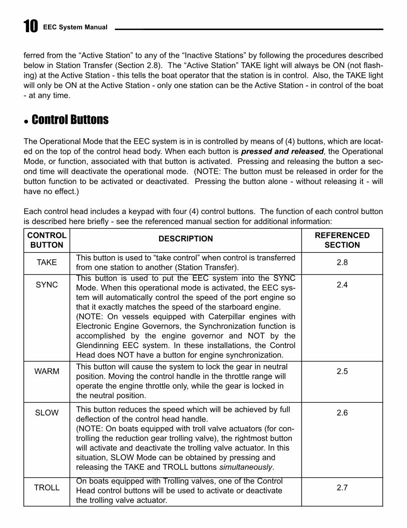
� Control Buttons
The Operational Mode that the EEC system is in is controlled by means of (4) buttons, which are locat-ed on the top of the control head body. When each button is pressed and released, the OperationalMode, or function, associated with that button is activated. Pressing and releasing the button a sec-ond time will deactivate the operational mode. (NOTE: The button must be released in order for thebutton function to be activated or deactivated. Pressing the button alone - without releasing it - willhave no effect.)
Each control head includes a keypad with four (4) control buttons. The function of each control buttonis described here briefly - see the referenced manual section for additional information:
CONTROL BUTTON
DESCRIPTION REFERENCED SECTION
TAKEThis button is used to “take control” when control is transferredfrom one station to another (Station Transfer).
2.8
SYNCThis button is used to put the EEC system into the SYNCMode. When this operational mode is activated, the EEC sys-tem will automatically control the speed of the port engine sothat it exactly matches the speed of the starboard engine.(NOTE: On vessels equipped with Caterpillar engines withElectronic Engine Governors, the Synchronization function isaccomplished by the engine governor and NOT by theGlendinning EEC system. In these installations, the ControlHead does NOT have a button for engine synchronization.
2.4
WARMThis button will cause the system to lock the gear in neutralposition. Moving the control handle in the throttle range willoperate the engine throttle only, while the gear is locked inthe neutral position.
2.5
SLOW This button reduces the speed which will be achieved by fulldeflection of the control head handle.(NOTE: On boats equipped with troll valve actuators (for con-trolling the reduction gear trolling valve), the rightmost buttonwill activate and deactivate the trolling valve actuator. In thissituation, SLOW Mode can be obtained by pressing andreleasing the TAKE and TROLL buttons simultaneously.
2.6
TROLLOn boats equipped with Trolling valves, one of the ControlHead control buttons will be used to activate or deactivatethe trolling valve actuator.
2.7
11Section 2.0 — Operating the EEC
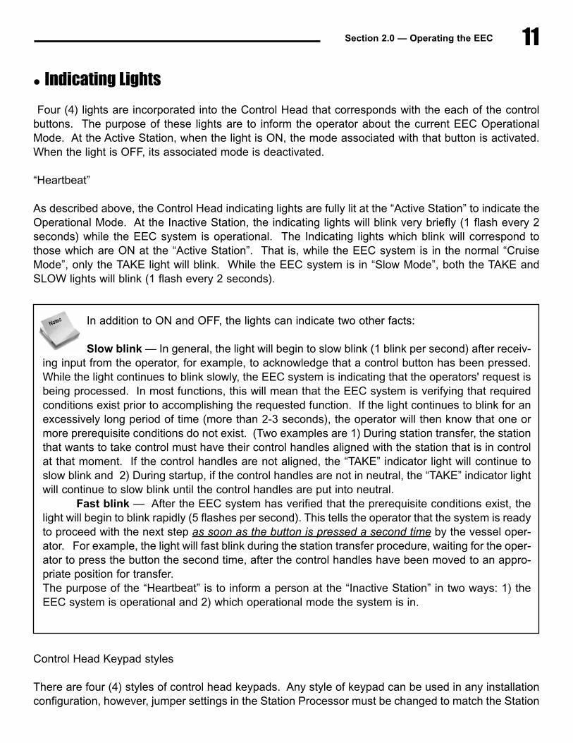
� Indicating Lights
Four (4) lights are incorporated into the Control Head that corresponds with the each of the controlbuttons. The purpose of these lights are to inform the operator about the current EEC OperationalMode. At the Active Station, when the light is ON, the mode associated with that button is activated.When the light is OFF, its associated mode is deactivated.
“Heartbeat”
As described above, the Control Head indicating lights are fully lit at the “Active Station” to indicate theOperational Mode. At the Inactive Station, the indicating lights will blink very briefly (1 flash every 2seconds) while the EEC system is operational. The Indicating lights which blink will correspond tothose which are ON at the “Active Station”. That is, while the EEC system is in the normal “CruiseMode”, only the TAKE light will blink. While the EEC system is in “Slow Mode”, both the TAKE andSLOW lights will blink (1 flash every 2 seconds).
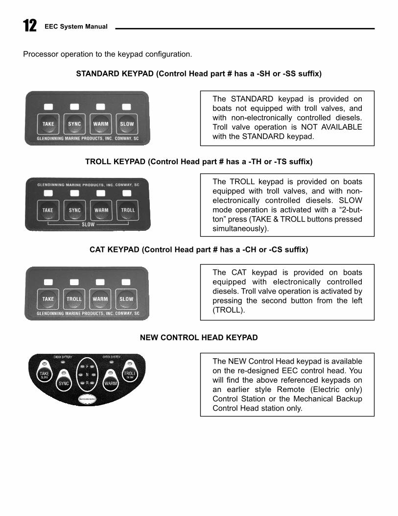
Control Head Keypad styles
There are four (4) styles of control head keypads. Any style of keypad can be used in any installationconfiguration, however, jumper settings in the Station Processor must be changed to match the Station
In addition to ON and OFF, the lights can indicate two other facts:
Slow blink — In general, the light will begin to slow blink (1 blink per second) after receiv-ing input from the operator, for example, to acknowledge that a control button has been pressed.While the light continues to blink slowly, the EEC system is indicating that the operators' request isbeing processed. In most functions, this will mean that the EEC system is verifying that requiredconditions exist prior to accomplishing the requested function. If the light continues to blink for anexcessively long period of time (more than 2-3 seconds), the operator will then know that one ormore prerequisite conditions do not exist. (Two examples are 1) During station transfer, the stationthat wants to take control must have their control handles aligned with the station that is in controlat that moment. If the control handles are not aligned, the “TAKE” indicator light will continue toslow blink and 2) During startup, if the control handles are not in neutral, the “TAKE” indicator lightwill continue to slow blink until the control handles are put into neutral.
Fast blink — After the EEC system has verified that the prerequisite conditions exist, thelight will begin to blink rapidly (5 flashes per second). This tells the operator that the system is readyto proceed with the next step as soon as the button is pressed a second time by the vessel oper-ator. For example, the light will fast blink during the station transfer procedure, waiting for the oper-ator to press the button the second time, after the control handles have been moved to an appro-priate position for transfer.The purpose of the “Heartbeat” is to inform a person at the “Inactive Station” in two ways: 1) theEEC system is operational and 2) which operational mode the system is in.
12 EEC System Manual
Processor operation to the keypad configuration.
STANDARD KEYPAD (Control Head part # has a -SH or -SS suffix)
TROLL KEYPAD (Control Head part # has a -TH or -TS suffix)
CAT KEYPAD (Control Head part # has a -CH or -CS suffix)
NEW CONTROL HEAD KEYPAD
The STANDARD keypad is provided onboats not equipped with troll valves, andwith non-electronically controlled diesels.Troll valve operation is NOT AVAILABLEwith the STANDARD keypad.
The TROLL keypad is provided on boatsequipped with troll valves, and with non-electronically controlled diesels. SLOWmode operation is activated with a “2-but-ton” press (TAKE & TROLL buttons pressedsimultaneously).
The CAT keypad is provided on boatsequipped with electronically controlleddiesels. Troll valve operation is activated bypressing the second button from the left(TROLL).
The NEW Control Head keypad is availableon the re-designed EEC control head. Youwill find the above referenced keypads onan earlier style Remote (Electric only)Control Station or the Mechanical BackupControl Head station only.

Section 2.0 — Operating the EEC 13
2.2 Control System Startup
The following procedure will activate the EEC system and bring it to the Cruise mode.
1. Verify that the Main Station Control head levers and the mechanical backup controlhead levers are in the Neutral position.
2. Turn on the “EEC Power Switch” or the circuit breakers which control power to theengine control system. The “EEC Power Switch” is normally located at the helm stationthat is equipped with the main station control head.
3. Immediately after the EEC Power Switch is turned on, the EEC system will begin ini-tialization procedures, including a transfer of control from mechanical backup to electron-ic. This process will take approximately 5 seconds. While the process is underway, theControl Head Indicator lights will “scroll” to indicate that power has been applied to theEEC system.
4. After approximately 5 seconds, the “TAKE” indicator light will remain ON (no blinking)and the WARM indicator light will remain ON (no blinking). The EEC system is now fullyoperational in the Warm up mode.
When starting the controls the EEC system immediately goes into the Warm Mode. The boat operator can
be assured that the engine transmission is in Neutral at engine start, and will remain in Neutral, until the sys-
tem is placed in normal run / cruise mode by pressing the WARM button on the control head keypad.
1. One of these diagnostics that the EP does during the startup process is to verify that the Main Station
Control Head (mechanical backup) control levers are in the "Neutral" detent position. If both Control
Levers are not in the Neutral position, the Control Head Indicator lights will not “scroll”. Rather, the TAKE
/ WARM / SLOW lights will slowly blink - pressing and releasing the TAKE button will have no effect. To continue the
System Startup process, reposition the control levers into the Neutral detent and the startup process will continue auto-
matically.
2. Step 4 of the above procedure applies to EEC Systems equipped with EP Software version 4 and later. (This soft-
ware began shipping in February, 1999). For EEC systems equipped with earlier versions of software, a “2 button”
press will be required to activate the Engine Control system, as follows:
a. Approximately 5 seconds after turning on the EEC Power Switch, the “TAKE” indicator light at the “main sta-
tion” will begin to blink slowly. Press and release the TAKE button 1 time.
b The “TAKE” indicator light at the “main station” will begin to blink quickly. Press and release the TAKE but-
ton a second time.
c The “TAKE” indicator light at the “main station” will remain ON. The EEC system is now fully operational in
the Cruise mode.
EEC System Manual14
REMOTE STATION CALIBRATION
After the EEC system startup, each remote station Control Head must be placed in the neutral detentposition for at least 5 sections for diagnostic testing. The completion of this testing will be indicated bythe TAKE light blinking once every two seconds (the “heartbeat”).
It is NOT NECESSARY that the remote station (electronic control only) Control Head levers be in theNeutral position during startup. However, it is necessary that the Station Processor recalibrate the con-trol head electronic position prior to transferring control to the remote station. This automatic calibra-tion process is done by returning the control levers to the Neutral position after the EEC system hasbeen started for approximately 4 seconds. After the Control Head calibration is completed, the TAKElight will begin to blink (“heartbeat”) indicating that the remote station is fully operational and that theremote station is an Inactive Station. Control transfer may be done at any time. If the remote stationcontrol head handles are in the Neutral position at the time of system startup, this calibration processwill be accomplished simultaneously with the main station calibration.
Prior to the automatic calibration process described above, the Control Head TAKE and SLOWIndicator lights will be ON - as if the remote station was in Slow Mode. This will alert the operator tothe fact that the remote handle has not yet been calibrated. Once the handles are placed in the Neutralposition, the SYNC / TROLL and WARM Indicator lights will be lit, showing that the automatic calibra-tion process is in progress.
2.3 Cruise Mode
� General Description
While the EEC system is in the Cruise Mode of operation, the system will respond as a normal “singlelever” control system. At the mid-point of the control lever position, the gear will be in the Neutral posi-tion. This will be felt on the control head by a detent position. Pushing the control lever forward onedetent will engage the ahead gear, at idle RPM. Pushing the control lever still farther forward will throt-tle up the engine, still while in the ahead gear.
Pulling the control lever aft out of the Neutral detent position will cause the gear to go into reverse gear.Pulling the control lever farther aft will also throttle up the engine with the gear in reverse.
There are 5 possible control handle positions while in the Cruise Mode:
o Ahead gear - with throttleo Ahead gear - engine idleo Neutral gear - engine idleo Astern gear - engine idleo Astern gear - with throttle

Section 2.0 — Operating the EEC 15
� Gear Sequence
The EEC system will automatically sequence the gears when the handle is moved from the 'aheadwith throttle' position to the 'astern with throttle' position. This means that the EEC system will onlyallow the gear to change position (ahead - neutral - astern) when the engine is at idle. And the enginethrottle will only be advanced when the gear position is fully engaged with either ahead or astern.
A) Throttle Delay (only applicable for EEC software version 4 and later)
On some boats, it is possible that a prolonged period of time (up to 3 or 4 seconds) will transpirebetween the time that the transmission control lever is moved into gear and the time that the propellershaft actually begins to turn. (By comparison, it only takes the EEC system Actuator approximately _half a second to move the transmission control lever from Neutral into Ahead or Astern gear). Theactual time delay that exists in any transmission will depend on various factors and adjustments insidethe transmission. During this period of time, it is possible that the boat operator will be able to speedup the engine RPM above idle. If the internal transmission delay is excessive, it is possible that geardamage may occur if the gear engagement occurs at a significant engine speed.
To prevent this possible damage to the gear, the EEC system can be calibrated to include an optionaltime delay between the moment that the transmission control lever reaches the Ahead or Astern posi-tion, and the moment that the engine is allowed to be accelerated above idle. The selected delay maybe set as 0 seconds (no delay), 0.5 seconds, 0.8 seconds or 1.0 second.
The following example will illustrate the operation of the throttle delay:
1. Control Handle is moved from Neutral to Ahead gear position and 50% engine throt-tle.2. Gear Actuator moves transmission control lever into Ahead position, immediately aftermovement of Control Head handle.3. Selected time delay is inserted (0.5 sec, 0.8 sec, 1.0 sec).4. After time delay, Throttle Actuator will move engine throttle / governor to selectedengine speed position.
B) Gear Delay (only applicable for EEC software version 5 and later)
The EEC system can also be calibrated to include a second type of delay, called “gear delay”. Geardelay will insert a time delay in the movement of the Gear Actuator when the control handle is movedfrom ahead or astern throttle position back to neutral or into the opposite gear. The purpose of Geardelay is prevent damage to the transmission if the gear is disengaged while the engine is at a signifi-cant speed above idle. Gear delay will allow the engine to slow down to idle (or to a speed close toidle) before the transmission is moved out of the gear position into neutral (see Section 8.1 — CustomCalibration Options).
The actual amount of gear delay is determined by two things:

EEC System Manual16
1. Gear delay setting in Engine Processor DIP switches. This setting can be changed atany time that the EEC system is off. The gear delay has 8 possible settings, from 0 sec-onds (no delay) to 12 seconds.
2. The amount of time that the engine has been operated at the set speed. This delay isproportional to the amount of time that the engine has been operated at any particularspeed. The following guidelines are used to determine the proportion: — the amount of delay time begins to build as the engine throttle is set above 1000 RPM.— The maximum delay time - that is, the delay time that is set by the DIP switch settingis reached when the engine has been operating at full throttle for 5 times the DIP switchsetting. — If the engine is operated at a high speed (90% of full throttle) and then slowed downto lower speed (30% of full throttle) for a short period of time, the gear delay will also bereduced in proportion to the slower engine speed.
The following example will illustrate the operation of the gear delay:
1. Boat is operating at cruise speed - ahead gear with throttle at 2000 RPM.2. Control Handle is rapidly moved to neutral gear position (engine idle).3. Throttle Actuator moves engine governor to idle position; engine RPM begins todescrease to idle, although this decrease is delayed due to natural engine inertia and the“windmilling” action of the propeller as the boat moves through the water.4. After Throttle Actuator has moved engine governor to idle, Gear Actuator maintainstransmission lever in ahead gear until predetermined time delay occurs (from 0 to 12 sec-onds).5. After completion of time delay “wait time”, the Gear Actuator will move tranmission toneutral.
C) Bump mode (only applicable for EEC software version 5 and later)
The Electronic Engine Control system includes a special “bump” mode which allows the boat operatorto control their engine speed with extreme precision. The bump mode allows the Throttle Actuatorposition (and therefore the engine governor / throttle) to be changed in very small increments, or
Examples1. If a 3 second gear delay is set on the EP DIP switches, the full 3 second gear delay will only bereached when the engine has been operated at full throttle for 15 seconds (5 x 3 second geardelay). If the engine is operated at a slower speed (less than full throttle), or for a shorter time that15 seconds, the time delay will be correspondingly less than 3 seconds.
2. If a 9 second gear delay is set on the EP DIP switches, the full 9 second gear delay will only bereached when the engine has been operated at full throttle for 45 seconds (5 x 9 second geardelay). If the engine speed is reduced to 50% throttle for approximately 15 seconds, the time delaywill be approximately 4.5 seconds, reflecting the slower engine operating speed.

Section 2.0 — Operating the EEC 17
bumps, by pressing and releasing the WARM (to increase engine speed) or SLOW / TROLL (todecrease engine speed). This feature is available at any time when the engine is being operated atany speed above idle - in normal “cruise” (“run”) mode, or in “warm” mode or in “sync” mode.
2.4 SYNC (Synchronization) Mode
� General Description
The purpose of the EEC Sync Mode is to automatically match the speed of one engine (the portengine) with the speed of the other engine (starboard engine) while cruising. By maintaining theengines at virtually the same speed, noise and vibration caused by engines operating “out of sync” iseliminated. While the Sync Mode is operational, the difference between the port and starboard enginewill normally not exceed 5 RPM.
� SYNC Mode Activation Procedure:
1. In order to activate the Synchronization Mode, the following must be true: 1) the gears are in the ahead position2) engine speed is above 950 RPM (Note: This speed will vary from boat to boat depending on various factors relatedto system calibration, engine governor cable connection geometry, and enginegovernor dynamics. If synchronization does not engage at 950 RPM, try advanc-ing the engines to a higher speed - perhaps 1500 RPM - and retry)3) engines speeds are within 250 RPM of each other for approximately 4 seconds
2. Whenever the engine RPMs meet the conditions stated above, press and release theSYNC button one time. The SYNC indicator light will go on. The EEC system will auto-matically adjust the speed of the Port engine to exactly agree with the speed of theStarboard engine.
1. Each bump will increase or decrease engine RPM approximately 15-20 RPM, although this value will from
one installation to another.
2. The bump mode adds or subtracts small amounts from the Control Head handle position (although the
handle does not move). If the Control Head is moved by the boat operator, the bump amount that has been added or
subtracted is reset to zero, and the engine speed will be determined by the position of the Control Head handle.
On boats equipped with Caterpillar ECM engines, the Glendinning EEC system Sync function is normally
not used. These engines are synchronized using the Caterpillar ECM system. Consult the Caterpillar
engine Operation Manual for details.
EEC System Manual18
3. While in Synchronization mode, the starboard engine speed can be changed. As thestarboard engine RPM changes, the speed of the port engine will be automatically adjust-ed to match the new speed of the starboard engine. While in Sync mode, the port enginecontrol lever will have no effect on the port engine - the EEC system is controlling the portengine for you. However, to make it easier to deactivate the Synchronization mode, itis good practice to keep the port engine control lever at approximately the same handleposition as the starboard engine.
4. While in Synchronization mode, the engine RPM can be operated at any speedbetween idle and full throttle. At idle speed, or at full throttle, the Synchronization modemay enter the “limit” mode - see Note 3 below.
� SYNC Mode Deactivation Procedure:
1. Align the port Control Head handle with the starboard engine control handle.
2. Press and release the SYNC button one time. Sync mode will be deactivated and theEEC system will be returned to the normal Cruise Mode (Section 3.3).
1. Normally, when deactivating the Synchronization mode, the port Control Head handle should be pre-
aligned with the starboard handle. If it is not, the engine control system will enter a special mode called
“transition Sync”. Rather than have the port engine RPM change drastically to the RPM corresponding to
the Control Head port handle position (which may be in any throttle position), the port engine will operate at approxi-
mately the same RPM as the starboard engine. This will continue until the port Control Head handle is aligned with
the starboard handle, at which point the port engine will return to normal, non-synchronized, “Cruise mode” operation.
2. If both engine control levers (port and starboard) are brought back to the neutral position, the Synchronization mode
will automatically deactivate without any action by the boat operator.
3. “Limit mode” (also called “psuedo-sync”) - If the engines are operated at or near idle speed or near full throttle, it is
possible that the Engine Control system will not have sufficient range of movement on the Port Engine governor to
make the speed adjustments necessary for synchronization. If this occurs, the Engine Processor will automatically
enter a “psuedo-sync” mode. In this mode, the Port engine speed will be approximately the same (probably within 40
RPM) as the Starboard engine, but the Port engine will not be “synchronized”. This condition will be indicated to the
boat operator by the Control head TAKE and SYNC lights flashing in tandem.
If this occurs, nothing should be done. The lights are blinking so that the boat operator knows that the EEC system is
not actively synchronizing engine speed. When the starboard engine is moved away from idle or full throttle a small
amount, the EEC system will restart the active synchronization mode and the TAKE and SYNC lights will return to their
normal “full on” (non-blinking) condition.
Section 2.0 — Operating the EEC
2.5 WARM Mode
� General Description
The purpose of the Warm Mode is to allow the engine to be throttled up while the gear is locked in theNeutral position. The Warm Mode is normally used during startup or while the vessel is at the dock,although it may be activated at any time.
� WARM Mode Activation Procedure:
1. Move the Control Head levers to the Neutral position. Warm Mode may only be acti-vated while the gear is in the Neutral position.
2. Press and release the WARM button one time. The WARM indicator light will turn ONindicating that the EEC system is in Warm Mode.
3. While the WARM light is ON, moving the control handle into the 'Ahead' detent willhave no effect - the gear actuator will be locked in the Neutral position. Advancing thethrottle past the 'Ahead' gear detent will cause the engine to increase in RPM. (Theengine will only accelerate if the handle is moved into the throttle range position. Movingit into the Astern position will have no effect.)
� WARM Mode Deactivation Procedure:
1. Move the Control Head levers to the Neutral position. Warm Mode may only be deac-tivated while the gear is in neutral.
2. Press and release the WARM button one time. The WARM indicator light will go OUT.The system is back in normal Cruise Mode (Section 2.3).
19
On EEC systems with software prior to version 4, Station Transfer is not possible while the Active Station is
in Warm Mode.
Station Transfer is possible while the Active Station is in Warm Mode on EEC systems with software version 4 or later.
2.6 SLOW Mode
� General Description
Slow Mode is essentially the same as Cruise Mode, with one difference: the maximum RPM that maybe obtained is approximately 50% of WOT (wide-open throttle). The purpose of slow mode is to givethe vessel operator approximately twice the precision compared with normal Cruise Mode. This isimportant while the vessel is being operated at slow speeds, such as during maneuvering or docking.
� SLOW Mode Activation Procedure:
1. Move the Control Head levers to the Neutral or Ahead / Astern idle detent position.Slow Mode may only be activated while the control handle is in one of the three detentpositions.
2. Press and release the SLOW button one time. The SLOW indicator light will go ON,indicating that the EEC System is in Slow Mode.
3. While in the Slow Mode, operation of the propulsion system is essentially the same asin normal Cruise Mode. The only differences are that engine throttle response will beslower and more precise, and maximum RPM obtainable will be approximately 50% ofmaximum.
� SLOW Mode Deactivation Procedure:
1. Move the Control Head levers to the Neutral or Ahead / Astern idle detent position.Slow Mode may only be deactivated while the control handle is in one of the three detentpositions.
2. Press and release the SLOW button one time. The SLOW indicator light will go OUT.The system is back in normal Cruise Mode (Section 3.3).
EEC System Manual20
For boats equipped with troll valves, it may be necessary for two buttons - TAKE and TROLL - to be pressed
simultaneously. See Control Head styles - section 2.1 for more information.
Section 2.0 — Operating the EEC 21
2.7 TROLL Mode
� General Description
Troll Mode is used on boats that are equipped with trolling valve actuators to allow a boat speed slow-er than that typically obtained with normal engine idle. This is done by moving a lever on the enginetransmission - called the “trolling valve” - which adjusts the gear oil pressure and allows the transmis-sion to slip. The amount of slippage is adjusted by the position of the trolling valve.
While in Troll Mode, the boat operator is able to control the gear position (Ahead, Reverse, andNeutral) and the trolling valve position (Full slip to no slip). To prevent transmission damage, theengine throttle will remain in idle at any time that the troll valve is not in the Full Lockup - no slip - posi-tion. (While in normal Cruise Mode, the trolling valve actuator is always in the Full Lockup - no slip -position.)
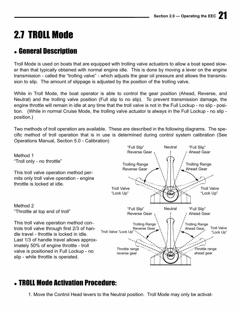
Two methods of troll operation are available. These are described in the following diagrams. The spe-cific method of troll operation that is in use is determined during control system calibration (SeeOperations Manual, Section 5.0 - Calibration)
� TROLL Mode Activation Procedure:
1. Move the Control Head levers to the Neutral position. Troll Mode may only be activat-
Method 1“Troll only - no throttle”
This troll valve operation method per-mits only troll valve operation - enginethrottle is locked at idle.
Method 2“Throttle at top end of troll”
This troll valve operation method con-trols troll valve through first 2/3 of han-dle travel - throttle is locked in idle.Last 1/3 of handle travel allows approx-imately 50% of engine throttle - trollvalve is positioned in Full Lockup - noslip - while throttle is operated.
“Full Slip”Reverse Gear
Trolling RangeReverse Gear
Troll Valve“Lock Up”
Troll Valve“Lock Up”
Trolling RangeAhead Gear
Neutral “Full Slip”Ahead Gear
“Full Slip”Reverse Gear
Trolling RangeReverse Gear
Trolling RangeAhead Gear
Troll Valve “Lock Up”
Throttle range reverse gear
Throttle range ahead gear
Troll Valve “Lock Up”
Neutral “Full Slip”Ahead Gear

EEC System Manual
ed while the control handle is in Neutral.
2. Press and release the TROLL button one time. In the engine compartment, theTrolling Valve Actuator will move the transmission trolling valve to the “full slip” position.The TROLL indicator light will go ON indicating that the EEC system is in Troll Mode.
3. While in the Troll Mode, moving the Control Head lever out of neutral into the Aheador Reverse gear position will have no effect on the propeller shaft - the trolling valve is in“full slip” and there will be no propeller shaft movement.
4. As the Control Head lever is pushed past the Ahead / Reverse position into the normalposition for engine throttle, the Troll Valve Actuator will move the trolling valve away from“full slip” toward the “full lockup” position, and the propeller shaft will begin to rotate.Propeller speed can be adjusted by moving the Control Head lever.
HIGH IDLE WHILE IN TROLL MODE
While in TROLL Mode it may be desirable to set your engine’s idle to a higher set-ting. Some boat operators have found that setting the engine idle higher while inTROLL Mode improves the performance of the trolling valves. Changes in engineidle will only take effect while the system is in TROLL Mode. Once in TROLL Mode(as outlined above) follow the following steps:
A) Make sure you are in TROLL Mode and handles are in the Neutral posiiton.
B) Press and Release the TAKE & SYNC buttons simultaneously to “bump up”engine idle setting (this “bump” size and amount, is a configurable settingdescribed in Sec. 8.1, pg. 117).
C) OR Press and Release the WARM & TROLL / SLOW buttons simultaneouslyto “bump down” engine idle setting.
D) Once desired setting is achieved Press & Release TAKE & WARM buttonssimultaneously to store your setting in memory. Again — the memorized engineidle setting only affects engine idle while in TROLL Mode.
E) To return engine idle setting to default — While in TROLL Mode Press &Release the WARM button (handles must be in Neutral position).
REFER TO YOUR MANUFACTURERS RECOMMENDATION FOR MAXIMUMRPMs IN TROLL MODE TO PREVENT TRANSMISSION DAMAGE.
22
Section 2.0 — Operating the EEC
� TROLL Mode DeActivation Procedure:
1. Move the Control Head levers to the Neutral position. Troll Mode may only be deacti-vated while the control handle is Neutral.
2. Press and release the TROLL button one time. In the engine compartment, the TrollingValve Actuator will move the transmission trolling valve to the “full lockup” position. TheTROLL indicator light will go OUT, indicating that the system is back in normal CruiseMode (Section 2.3).
2.8 Station Transfer
� General Description
The purpose of the Station Transfer function is to allow the vessel operator to transfer control from onestation to another. (This could also be described as changing the control station which is the “ActiveStation” - the “Active Station” is always that station that is in control of the EEC system.)
In order to understand the proper procedure for station transfer, two concepts must be kept in mind:
1. Control can be transferred FROM one station (the “Active Station”) TO any other “Inactive sta-tion” at any time. The propulsion plant may be in any position during the transfer process -ahead, astern, neutral, idle, or full throttle. If stations are transferred while the gears are inneutral, the “Inactive” (receiving) Station control levers must also be in the neutral gear position.If stations are transferred while the engines are in gear, the “Inactive” (receiving) Station controllevers must be: 1) in neutral, or, in the same gear as the “Active Station” (i.e., ahead / astern)and 2) at or below the throttle position of the “Active Station”. (That is, the Inactive Station con-trol lever must be at or below the throttle position of the Active Station).
2. Control transfer is a two step process. The first step involves signaling the EEC system thata control transfer is desired. This is done by pressing the TAKE button one time at the “InactiveStation” where you desire to take control. The EEC system will analyze the system status anddetermine whether control can be transferred. (This primarily checks to see if the “InactiveStation” control levers are in a position that is appropriate for station transfer). If the EEC con-firms that station transfer is permissible, this will be signaled by a quick flashing TAKE light at
23
This is only true for Engine Controls that include Version 4 software or higher.
For systems equipped with older software, station transfer can only occur while the system is inCruise, Sync, or Slow mode only. (Station transfer is not allowed while the system is in Warm or
Troll mode).
EEC System Manual
the “Inactive Station”. If some parameter prevents taking control (such as the Inactive(Receiving) Station control lever being in Reverse while the Active (In-control) Station is inAhead) the TAKE light will 'slow blink'. It will continue to 'slow blink' until the parameter ischanged or until a “time-out” is reached - approximately 12 seconds after first pressing the TAKEbutton.
� Station Transfer Procedure:
1. At the Inactive Station where you desire to take control, press and release the TAKEbutton 1 time. The Inactive Station control levers can be in any position when the buttonis pressed.
2. If Inactive Station control levers are in a position that is allowable for control transfer(see above), the TAKE light will begin to 'quick blink' and the control head will beep quick-ly.
3. If Inactive Station control levers are not in an appropriate position, TAKE light will 'slowblink'. The Inactive Station control levers should be moved to an appropriate transferposition, as described above. Doing this will cause TAKE light to 'quick blink'.
4. When TAKE light is 'quick blinking', press and release the TAKE button again (1 time).Control will immediately be transferred to the Inactive Station. This control station nowbecomes the Active Station and has full control of the EEC system.
24
The EEC system only allows a 12-second time period to make adjustments to the position of the Inactive
Station control levers. If the control levers are not in an appropriate transfer position by the end of 12 sec-
onds, the EEC system will revert back to a normal Cruise,Sync, or Slow Mode.
A good method of transferring stations while underway (ahead, with throttle) is to do the following:1) Press and release the TAKE button one time at the Inactive Station2) Advance the control handles to the full throttle ahead position. (The engine speed will not change sincethe control station is still Inactive). The TAKE light will blink slowly, indicating that the control handles are
beyond the allowable position for station transfer.3) Pull the control handles back slowly to the point where the TAKE light begins to blink quickly. At this point the con-trol handles are aligned with the current engine speed.4) Press and release the TAKE button again (one time). Control will be transferred immediately and the engine RPMwill be virtually unchanged.
Remember, Station transfer is only possible when:
Both Inactive Station control levers are in Neutral GearOR
Both Inactive Station control levers are in the same gear as Active Station (ahead/ astern), and at the same or lower throttle setting than Active Station.

Section 2.0 — Operating the EEC
2.9 Alarm Mode / Mechanical Backup Operation
� Alarm Mode Sequence
During normal operation, the Engine Processor continually monitors the operation of the entire controlsystem to ensure that the system is functioning properly. In the event that a problem is discovered dur-ing these routine and continuous diagnostic checks, the EEC system will enter an “alarm mode”. Thefollowing will occur when the “alarm mode” is entered:
1) The system actuators will remain at their “last- commanded” position; that is, theengine throttle and gear will remain in the same position they were in when the systementered the alarm mode.
2) The actuator solenoids will release, allowing the system to transfer automatically tomechanical backup operation (if equipped).
3) All four (4) LED's on the control head will begin to blink in unison at all helm stations.The Control Head beeper will also begin to beep simultaneously.
4) The error code associated with the specific alarm condition will be indicated on theEngine Processor LED's.
5) The error code is stored in the system memory as an aid to troubleshooting the prob-lem later.
� Mechanical Backup Procedure
When the EEC system enters “alarm mode” as indicated by the (4) Control Head LEDs blinking simul-taneously, the vessel operator should immediately accomplish the following:
1) If the vessel is being controlled at the Main control station, the one equipped withthe integrated mechanical backup, the control system will revert to mechanical operationimmediately.
2) If the vessel is being controlled at one of the remote control stations (electron-ic control only), the vessel operator should move to the mechanical backup station andregain mechanical control. This is done by moving the Main control station (equipped
25
If the vessel is being operated in the troll mode when the system enters alarm mode, the troll valves mustbe manually closed. There is no automatic mechanical backup system for the troll valve actuator. Do notincrease engine throttle above the speed allowed by the transmission manufacturer while the troll valve isopen. DAMAGE CAN OCCUR!

EEC System Manual
with the mechanical backup system) to the same approximate position (i.e., Ahead with60% throttle) as the remote control station when the system entered the alarm mode.
3) Investigating for the cause of the system failure can begin immediately or may bedelayed until the vessel reaches its final destination:
a) Immediate investigation — Leave EEC system ON in alarm mode withControl Head LEDs blinking and beeper sounding. DO NOT turn off the EECPower Switch. Remove the EP Access and identify the LED's which are lit bright-ly. Once this information is recorded, the power to the Engine Processor may beturned off by pressing and releasing the EP circuit breakers. This will cause theControl Head LED's and beeper to cease blinking / beeping. Switch OFF the EECpower switch at the main panel.
b) Delayed investigation — Turn OFF the EEC system by switching the EECpower switch at the Main helm station to the OFF position. The Control HeadLED's and beeper will cease. When the vessel has been tied up, follow the pro-cedures under Section 5.1 “Troubleshoot Mode” to read the stored LED informa-tion.
4) Call GMP personnel with a description of the problem and LED error code information.(See Section 5)
� System Failure — No Alarm
There are 3 conditions where the EEC system may fail without entering the Alarm Mode:
1) DC power failure — Although dual battery inputs make the possibility of this occur-ring remote, a sudden and continuous loss of DC power input to the Engine Processor
26
If electronic control is lost and then regained using the mechanical backup system, it is possible to attemptto restart the EEC while the vessel is underway. This may be done by placing the gear in the Neutral posi-tion, and proceeding with the System Startup procedures described in Section 2.2. The alarm codes thatwere stored during the original system failure will remain stored in system memory.
In some cases, it may be necessary to “jiggle” the control handle a small amount in one direction or the otherin order to regain mechanical backup control. Whether or not this small amount of control handle movementis necessary depends upon a number of factors, including: control handle position, length of mechanicalbackup cables, cable adjustment during installation, etc.
Immediate investigation should only be made if the vessel is tied up at the dock. If the vessel is underway,investigation of the alarm should be delayed until the vessel returns to the dock (see Delayed Investigation- next paragraph).

Section 2.0 — Operating the EEC 27
would make the EEC system stop “dead in its tracks” (NOTE: A slow loss of DC batteryvoltage [i.e., battery charger failure] would be indicated by the system entering “alarmmode” due to low input voltage. This alarm code would be stored in system memory.).
2) Power Switch power failure — A failure to supply power to the Power Switch at theMain station will have the same effect as a DC power failure.
3) Internal diagnostic failure — The diagnostic system fails to detect a system failure,or the diagnostic system has an internal failure causing it to cease operation.
If the system were to fail from one of the 3 causes listed above, the vessel operator would detect thisfailure in one of three ways:
1) The TAKE light, which is always fully ON (illuminated) at the Active Station, will go out.
2) If the vessel is being controlled from the mechanical backup helm station, the controlhandles may be much harder to move.
3) If the vessel were being controlled from a remote, electronic-only, station, movementof the control handles would result in no change of engine throttle and gear position. Inthis situation, mechanical control should be immediately regained at the mechanicalbackup station.
� Mechanical Backup System (detailed description)
General
A separate mechanical Control Head by another manufacturer may be used with the GlendinningMechanical Backup feature, however, the mechanical backup feature WILL NOT be integrated with theseparate Control Head. When using another manufacturers Control Head, it will be necessary for theboat operator to take mechanical control over the vessel from this dedicated station.
One of the key features of the Glendinning Electronic Engine Control system is the integrated mechan-ical backup system. In essence, the EEC system is really two control systems that operate in parallelto one another:
1) A computer controlled electro-mechanical system that permits control of gear andthrottle from up to six different locations and . . .
The EEC system may be shifted to Mechanical backup operation at any time. This is done by simply turn-ing OFF the EEC power switch at the mechanical backup helm station. The EEC system will be immediate-ly de-energized and control may be regained using the mechanical backup system.
EEC System Manual28
2) A mechanical control that permits control of the gear and throttle from one helm sta-tion. While the system is in operation, the specific system that is controlling the enginethrottle and gear is determined by a custom designed coupler mechanism on the top ofthe actuator which is located in the engine room. In the electronic operation, the couplermechanism connects the electro-mechanical actuator output to the engine throttle andgear; the position and movement of the mechanical control system is ignored. Inmechanical backup operation, the coupler mechanism connects the control cable fromthe mechanical backup station to the engine throttle and gear; the position and move-ment of the electro-mechanical actuator is ignored.
Control Changeover — Electronic / Mechanical
In order to understand the method of transfer between the electronic and mechanical control systems,the concept of alignment must be understood. Control may only be transferred between the two par-allel control systems when they are both in the same position. For example, if the vessel is being oper-ated in the ahead gear at 2000 RPM in electronic control, the mechanical control system must bemoved to a position that corresponds to “Ahead/ 2000 RPM” in order to regain mechanical control.(This alignment must only be approximate for transfer to occur).
When the vessel is being controlled electronically from the mechanical backup station, the electron-ic control system and the mechanical control are generally aligned. That is, when the system enters“alarm mode” when the system is being controlled electronically at the Main helm station, control willbe transferred immediately from electronic to mechanical. :
When the vessel is being controlled electronically from a remote, electronic-only, control station, itwill be necessary to “align” the mechanical handles up with the current position of the engine throttleand gear in order to regain control. This may be done very simply by pushing the control lever in thedirection of vessel movement (ahead or astern) and continuing to push the lever until a change isobserved in the engine speed (RPM). At the moment that the mechanical control system is alignedwith the electronic system, the engine will either increase or decrease slightly in RPM. The enginesmay now be controlled mechanically.
Control transfer from mechanical operation to electronic is accomplished every time that the EECsystem is turned on. During system startup, the electronic control system automatically aligns itself upwith the mechanical control. This is the reason why the main control station handles must be in theNeutral position prior to turning on the EEC power switch. (see section 4.2).
In some cases, it may be necessary to “jiggle” the control handle a small amount in one direction or theother for this transfer to occur. Whether or not control will be immediate depends upon a number of factors,including: control handle position, length of mechanical backup cables, cable adjustment during installation,etc.

Section 3.0 — Installing the EEC 29
3.0 Installing the EEC SystemBefore beginning the installation of the Glendinning Electronic Engine Control (EEC), proper consider-ation and pre-planning should be given to several very important parts of the EEC system. Proper plan-ning of the installation will help to insure that the EEC system will operate correctly and within specifi-cation. Failing to properly plan will decrease the reliability of the EEC system and possibly disablesome of the product's inherent safety features.
3.1 Pre-Installation PlanningThe two most critical parts of the EEC system installation are the following:
Component Location — In order for the integrated mechanical backup system to work properly, andto maximize the overall reliability of the EEC system, the proper location of the Actuators, EngineProcessor, and Mechanical backup control head is extremely important.
EEC system power supply — The EEC system includes a reliability feature called “dual batteryinputs”. One of the most critical factors in determining the reliability of any electrical equipment is pro-viding a solid source of electrical power. In order to increase the probability that the Electronic EngineControl will be able to receive a solid source of electrical power, the EEC system has been designedfor power inputs from two (2) independent batteries. Failing to properly provide power from (2) inde-pendent battery sources will disable this important safety feature!!
� Component Locations
The most important pre-installation decisions which must be made are the proper locations for sever-al of the EEC components, specifically the Actuators, Mechanical Backup Control Head, and EngineProcessor. Properly installed, the EEC system will work according to specifications. Improperlyinstalled, overall reliability of the EEC system will be reduced and some system features, such asmechanical backup operation, will be degraded.
Actuator Location
It cannot be emphasized strongly enough: the location of the EEC system actuators is the mostimportant factor in the satisfactory operation of the integrated mechanical backup system (If nomechanical backup system is used, or if the system is "non-integrated", actuator location is less impor-tant). This is because the location of the Actuators has a direct impact on the routing of the controlcables. In general, and almost without exception, there is a direct connection between good routing ofthe control cables and the operation of the mechanical backup system - good control cable routing willresult in good mechanical backup operation, bad control cable routing will result in bad mechanicalbackup operation. Some factors which contribute to good Actuator location are the following:

EEC System Manual30
— Straight cable runs with the minimum number of bends - The most efficient cable con-figuration is a straight cable run with no bends. Although this will yield maximum cable efficien-cy, it is not practical in a typical installation. Therefore, to maximize cable efficiency, the Actuatorlocations should be chosen which will reduce or eliminate the total number of bends in the con-trol cables. (This includes the control cables which connect the Actuator to the engine / gear aswell as the mechanical backup cables).
— Cable bends should have a large radius - The claims of the control cable manufacturersnotwithstanding, control cables are far more efficient with larger diameter bends rather thansmaller diameter. Where possible, large, sweeping turns should be used rather than smaller,tighter turns.
As an aid in determining the best location for the EEC system actuators, several drawings have beenprepared which depict some typical installations. Please review these drawings, which are located atthe end of this section, to see if any of these layouts would be applicable to your specific installation.
Mechanical Backup Control Head
Determining a good location for the mechanical backup control head is important, although the loca-tion of this component is frequently pre-determined by the boat owner or yacht designer. Two issuesmust be considered in the installation of the mechanical backup cables:
— Clearance for mechanical backup levers - Several levers are mounted below and on the
As part of its service to its customers, Glendinning Marine Products, Inc. offers, at no charge to the cus-tomer, a plan review service for EEC system installations. In order to take advantage of this free service,fax or mail a sketch of the proposed installation to our EEC Application Manager. Although this sketch canbe very simple, it should show the general arrangement of the engine and gearbox, points of attachment for
the control cables, location for mechanical backup cable entry into the engine room, and proposed location of EEC sys-tem components.
A WORD REGARDING CONTROL CABLES. . .
To ensure good operation of the Engine Control mechanical backup system it is important that good quali-ty control cables be used. Although the EEC system components - Actuators and Mechanical backup con-
trol head - are designed to accommodate any standard Type 33 control cable, there are many grades and qualities ofcontrol cables available on the market. Like the position of the Actuators described above, the quality of the controlcables will have a direct impact on the function of the mechanical backup after the installation is completed. In gener-al, the use of standard quality “Morse Red Jaket” cables (or Teleflex equivalent) is not recommended. Some installershave had acceptable result using “Morse Supreme” cables (or Teleflex equivalent). Our recommendation, based ondecades of experience with control cables, is to use Type 95 control cables manufactured by Glendinning MarineProducts, Inc. Our testing has found these cables to have consistently the highest efficiency, smoothest operation, andgreatest flexibility of any control cable on the market. NW Control cables by Glendinning are available fromGlendinning Marine Products, Lewis Marine Supply, or other marine distributors.On aftermarket installations, it is generally not recommended to reuse the existing control cables for the mechanicalbackup system.
Section 3.0 — Installing the EEC 31
side of the mechanical backup control head. In some cases, there is insufficient clearancebelow the control head to allow for unimpeded movement of these levers or for their installationor servicing.
— Control cable routing - The issues discussed above regarding control cable routing to theactuators also apply here. Large sweeping bends should be used rather than tight turns. Laycables out straight prior to installation. Cycle test cable during installation to determine if anycompound bends have created noticable drag in cable operation.
Engine Processor
The following considerations should be kept in mind when identifying a good location for the EngineProcessor:
— Environmental conditions - The Engine Processor should be mounted in an area that isrelatively dry and cool. Although the Engine Processor electronic components are reasonablywell-sealed from moisture, the product enclosure is not designed for constant direct contact withwater. Since the longevity of electronic components is reduced in high temperature environ-ments, it is best to find an area of the engine compartment that is not exposed to temperatureextremes. Although the Engine Processor has been designed for installation in the engine com-partment, the design of the product does allow it to be installed external to the engine compart-ment, as long as the wire length from the Actuators is 20' or less. The Engine Processor shouldbe installed where there is some air movement or ventilation. DO NOT MOUNT ON ENGINE!
— Accessible - During system calibration or troubleshooting, it will be necessary for theinstaller or repair technician to have access to the internal connections of the Engine Processor.In view of this, the Engine Processor should be mounted in a relatively accessible area.
— The Engine Processor can be mounted in any orientation - on the overhead or deck, oron the bulkhead.
� Example Installation Diagrams
The following drawing illustrates a typical location for the Actuators where the mechanical backupcables enter the engine compartment at the aft rear corners. The Actuators are mounted on the out-board hull, with the Actuator control cable mounting plate oriented toward the aft end of the boat. Thecontrol cables to the engine and gear make a “rear entry” and are connected to the Actuators througha single 180 degree bend.
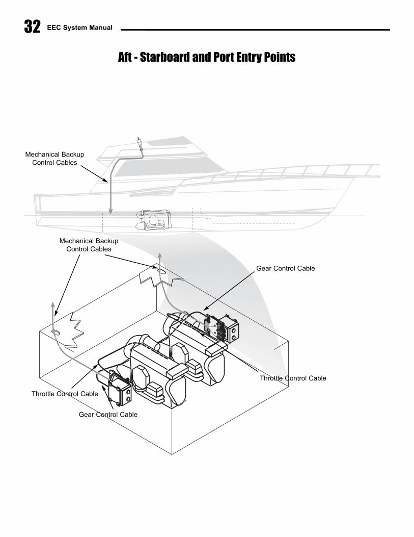
EEC System Manual32
Aft - Starboard and Port Entry Points
Mechanical BackupControl Cables
Mechanical BackupControl Cables
Throttle Control Cable
Gear Control Cable
Throttle Control Cable
Gear Control Cable
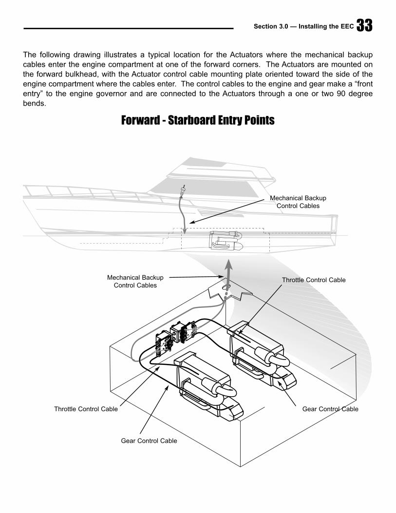
Section 3.0 — Installing the EEC
The following drawing illustrates a typical location for the Actuators where the mechanical backupcables enter the engine compartment at one of the forward corners. The Actuators are mounted onthe forward bulkhead, with the Actuator control cable mounting plate oriented toward the side of theengine compartment where the cables enter. The control cables to the engine and gear make a “frontentry” to the engine governor and are connected to the Actuators through a one or two 90 degreebends.
33
Forward - Starboard Entry Points
Mechanical BackupControl Cables
Mechanical BackupControl Cables
Throttle Control Cable
Gear Control Cable
Throttle Control Cable
Gear Control Cable
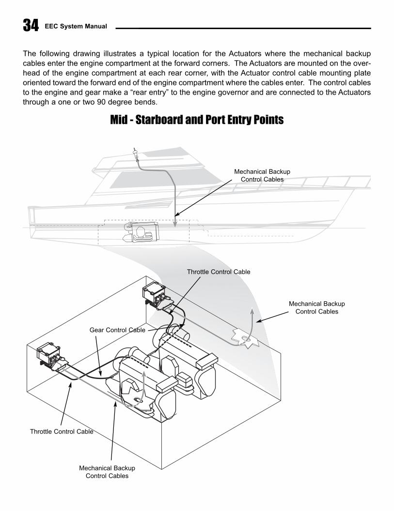
EEC System Manual
The following drawing illustrates a typical location for the Actuators where the mechanical backupcables enter the engine compartment at the forward corners. The Actuators are mounted on the over-head of the engine compartment at each rear corner, with the Actuator control cable mounting plateoriented toward the forward end of the engine compartment where the cables enter. The control cablesto the engine and gear make a “rear entry” to the engine governor and are connected to the Actuatorsthrough a one or two 90 degree bends.
34
Mid - Starboard and Port Entry Points
Mechanical BackupControl Cables
Mechanical BackupControl Cables
Mechanical BackupControl Cables
Throttle Control Cable
Throttle Control Cable
Gear Control Cable
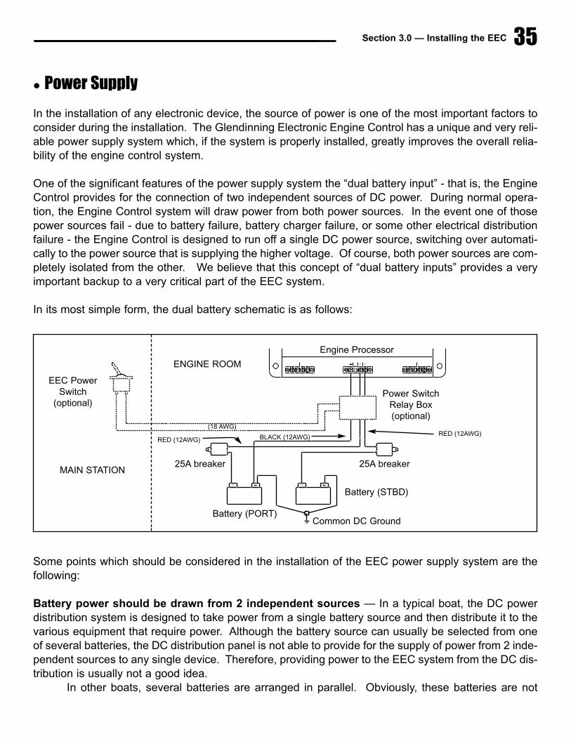
Section 3.0 — Installing the EEC 35
� Power Supply
In the installation of any electronic device, the source of power is one of the most important factors toconsider during the installation. The Glendinning Electronic Engine Control has a unique and very reli-able power supply system which, if the system is properly installed, greatly improves the overall relia-bility of the engine control system.
One of the significant features of the power supply system the “dual battery input” - that is, the EngineControl provides for the connection of two independent sources of DC power. During normal opera-tion, the Engine Control system will draw power from both power sources. In the event one of thosepower sources fail - due to battery failure, battery charger failure, or some other electrical distributionfailure - the Engine Control is designed to run off a single DC power source, switching over automati-cally to the power source that is supplying the higher voltage. Of course, both power sources are com-pletely isolated from the other. We believe that this concept of “dual battery inputs” provides a veryimportant backup to a very critical part of the EEC system.
In its most simple form, the dual battery schematic is as follows:
Some points which should be considered in the installation of the EEC power supply system are thefollowing:
Battery power should be drawn from 2 independent sources — In a typical boat, the DC powerdistribution system is designed to take power from a single battery source and then distribute it to thevarious equipment that require power. Although the battery source can usually be selected from oneof several batteries, the DC distribution panel is not able to provide for the supply of power from 2 inde-pendent sources to any single device. Therefore, providing power to the EEC system from the DC dis-tribution is usually not a good idea.
In other boats, several batteries are arranged in parallel. Obviously, these batteries are not
---- + +
+ +
EEC Power Switch
(optional)
MAIN STATION
ENGINE ROOM
(18 AWG)
25A breaker 25A breaker
RED (12AWG)RED (12AWG) BLACK (12AWG)
Power Switch Relay Box (optional)
Engine Processor
Battery (PORT)
Battery (STBD)
Common DC Ground

EEC System Manual36
independent - that is, the voltage observed at one battery terminal will be the same at the other bat-tery terminal. It is important that each battery source be completely independent of the other.
Draw power from the battery as close to the battery positive terminal as possible — It cannot beoveremphasized that providing a secure, uninterrupted source of power to the EEC system is vitallyimportant to the reliable operation of the control system. For this reason, it is best that the EEC powerbe drawn as close as possible to the battery positive terminal, without having various componentswhich may interrupt the flow of current to the control system
Circuit protection — Per the ABYC guidelines, some type of current protection - circuit breaker orfuse - must be installed within 7 inches (17 cm) of the connection to the source of power. It is veryimportant to understand that circuit protection is installed for the protection of the wire, not the EECsystem. The EEC system has its own internal current protection and does not need any external fuse.However, the wire which connects the EEC to the boat power must be protected in case of chafing orother damage. In order to not limit power to the EEC system during normal operation, a minimum 25Amp fuse or circuit breaker must be installed. (If a 30 Amp fuse or circuit breaker is used, then it isnecessary that 10 AWG wire - or larger - is used to connect the EEC system to its power source).
Battery ground — The dual battery system requires that the battery positive terminals be at roughlythe same voltage. In order for the battery positive terminals to be at the same voltage, it is necessarythat the negative terminals of the batteries be connected at some common point. This is normal marineelectrical practice and is specified in the ABYC voluntary guidelines. Prior to the final electrical hookupof the EEC system, the installer should verify that the battery ground terminals are connected at somecommon point.
3.2 Cable ConnectionsPrior to installation of the Electronic Engine Control (EEC) system, it is vital to determine the actualdirection of travel of the control cables that connect to the engine governor and transmission controllevers. Check the following items and write them in the space provided - this information will be need-ed later for EEC system calibration and for the connection of the mechanical backup cables.
In order to follow the two recommendations above - draw power close to battery positive terminal, and pro-vide circuit protection for the interconnecting wiring - it is normal that the current protection - fuse or circuitbreaker - will be physically located in the engine compartment. However, it is inconvenient to require theboat owner to have to go to the engine compartment to start up the Engine Control system each time that
he / she wishes to use the boat. For this reason, Glendinning Marine Products has an optional “Power Switch RelayUnit” (PSRU) which allows the boat owner to remotely turn on or turn off the engine control system from the helm sta-tion. When the PSRU is used, the EEC circuit protection is typically left in the “ON” position. The PSRU only requiresthat a small (2 conductor, 18 gauge) wire be run from the engine compartment to the helm station. For more details,see Section 2.5-E of the manual.
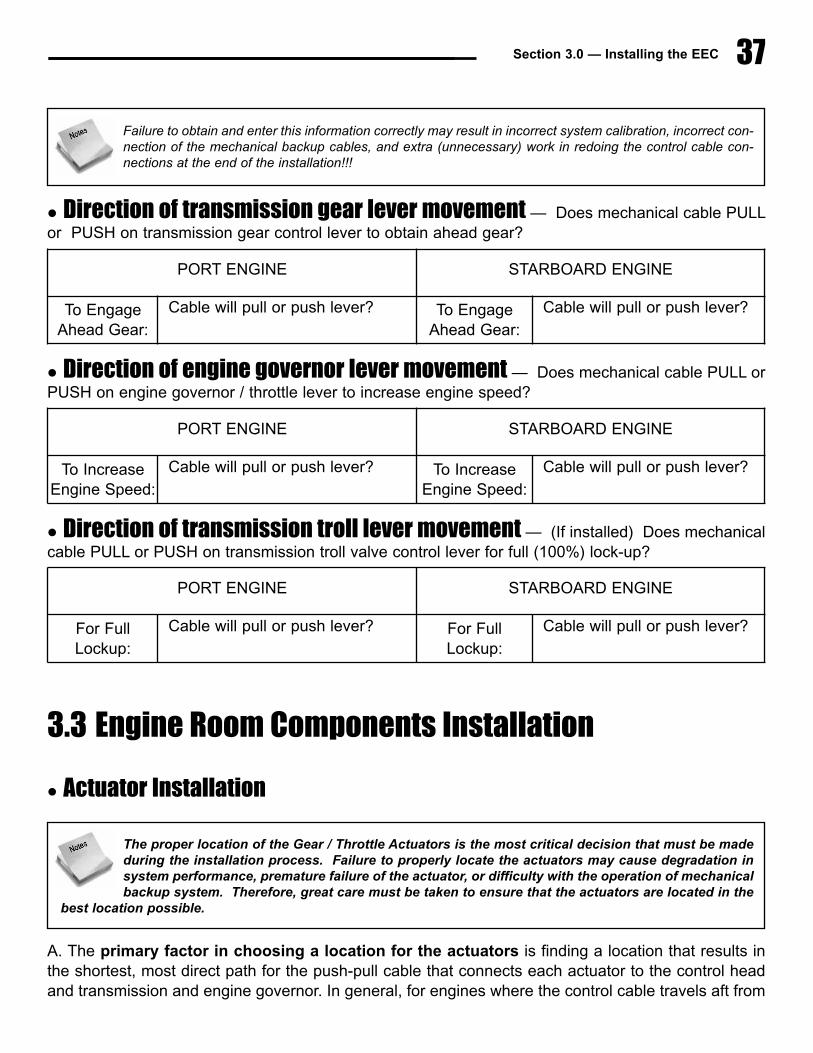
Section 3.0 — Installing the EEC 37
� Direction of transmission gear lever movement — Does mechanical cable PULLor PUSH on transmission gear control lever to obtain ahead gear?
� Direction of engine governor lever movement — Does mechanical cable PULL orPUSH on engine governor / throttle lever to increase engine speed?
� Direction of transmission troll lever movement — (If installed) Does mechanicalcable PULL or PUSH on transmission troll valve control lever for full (100%) lock-up?
3.3 Engine Room Components Installation
� Actuator Installation
A. The primary factor in choosing a location for the actuators is finding a location that results inthe shortest, most direct path for the push-pull cable that connects each actuator to the control headand transmission and engine governor. In general, for engines where the control cable travels aft from
Failure to obtain and enter this information correctly may result in incorrect system calibration, incorrect con-nection of the mechanical backup cables, and extra (unnecessary) work in redoing the control cable con-nections at the end of the installation!!!
PORT ENGINE STARBOARD ENGINE
To Engage Ahead Gear:
Cable will pull or push lever? To Engage Ahead Gear:
Cable will pull or push lever?
PORT ENGINE STARBOARD ENGINE
To IncreaseEngine Speed:
Cable will pull or push lever? To IncreaseEngine Speed:
Cable will pull or push lever?
PORT ENGINE STARBOARD ENGINE
For FullLockup:
Cable will pull or push lever? For FullLockup:
Cable will pull or push lever?
The proper location of the Gear / Throttle Actuators is the most critical decision that must be madeduring the installation process. Failure to properly locate the actuators may cause degradation insystem performance, premature failure of the actuator, or difficulty with the operation of mechanicalbackup system. Therefore, great care must be taken to ensure that the actuators are located in the
best location possible.

EEC System Manual38
the engine governor / throttle lever, the actuator will be mounted in the aft section of the engine room.Conversely, for engines where the control cable heads forward from the engine governor lever, theactuator will be mounted toward the forward end of the engine room. In general, the length of the con-trol cable from each actuator to the transmission and engine governor should not be greater than 10feet and 180 total degrees of bend. (Longer lengths may be used after review and approval of thephysical layout of the product installation by Glendinning Marine Products).
One reason why a short cable to the engine governor is critical has to do with engine synchronization.In order to accurately synchronize one engine to the other, it is necessary to position the governor withan accuracy of less than five thousandths (0.005") of an inch. Any unnecessary bend in the controlcable to the governor lever, or using a cable that is longer than necessary, will result in lost motionbetween the actuator and engine, causing a reduction in synchronization accuracy. This greater lengthwill also increase the difficulty in controlling the engine governor using the mechanical backup system.
B. A second important factor which should be considered in correctly positioning the actuators is therouting of the mechanical backup cables. The shortest and most direct routing of the mechanical back-up cables is important for smooth and easy operation of the mechanical backup system.
C. Other factors which should be considered are:
� The actuators can be mounted in any orientation — on the bulkhead, overhead, ordeck. The actuators should NOT be mounted on the engine.
� Control cable length — The push-pull cables between Actuator and Engine Throttleor Gear control lever should be no longer than 10 feet (unless installation layout isapproved by Glendinning Marine Products).
� The actuators should be protected from direct exposure to water or excessiveheat. The Glendinning EEC actuator has been carefully designed to withstand exposureto saltwater normally encountered in an engine room and resist the effects of marine cor-rosion. However, installing the actuator in a location that subjects it to excessive saltwa-ter exposure will cause premature wear and increase the possibility of system failure.Care should be taken to not locate the actuator near engine room vents, stern tube pack-ing glands or other sources of saltwater spray. Shielding the actuator from sources ofexcessive heat, such as the engine exhaust manifolds, should also be taken intoaccount.
� Maintainability — The actuator should be located in a position that is accessible forcontrol cable adjustments.
Push-Pull control cables must be run straight for 9 - 12” from the mounting clamp pointbefore making any bends.
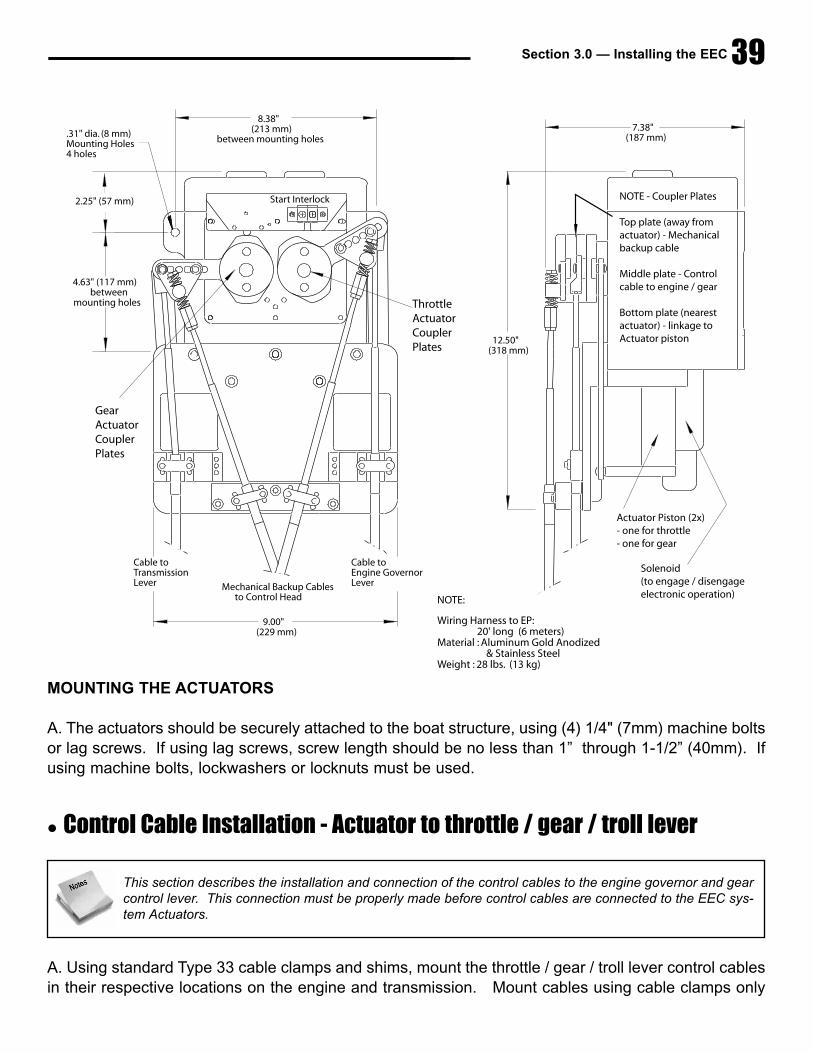
Section 3.0 — Installing the EEC 39
MOUNTING THE ACTUATORS
A. The actuators should be securely attached to the boat structure, using (4) 1/4" (7mm) machine boltsor lag screws. If using lag screws, screw length should be no less than 1” through 1-1/2” (40mm). Ifusing machine bolts, lockwashers or locknuts must be used.
� Control Cable Installation - Actuator to throttle / gear / troll lever
A. Using standard Type 33 cable clamps and shims, mount the throttle / gear / troll lever control cablesin their respective locations on the engine and transmission. Mount cables using cable clamps only
7.38"(187 mm)
8.38"(213 mm)
between mounting holes
2.25" (57 mm)
4.63" (117 mm) between
mounting holes
.31" dia. (8 mm) Mounting Holes4 holes
Mechanical Backup Cables to Control Head
Cable toTransmission Lever
Cable toEngine GovernorLever
9.00"(229 mm)
12.50"(318 mm)
NOTE:
Wiring Harness to EP: 20' long (6 meters)Material : Aluminum Gold Anodized & Stainless SteelWeight : 28 lbs. (13 kg)
Start Interlock NOTE - Coupler Plates
Top plate (away fromactuator) - Mechanicalbackup cable
Middle plate - Controlcable to engine / gear
Bottom plate (nearestactuator) - linkage toActuator piston
Actuator Piston (2x)- one for throttle- one for gear
Solenoid(to engage / disengageelectronic operation)
GearActuatorCouplerPlates
ThrottleActuatorCouplerPlates
This section describes the installation and connection of the control cables to the engine governor and gearcontrol lever. This connection must be properly made before control cables are connected to the EEC sys-tem Actuators.

EEC System Manual40
— DO NOT CONNECT THE CABLE ENDS TO THE CONTROL LEVERS AT THIS TIME.NOTE: we recommend premium grade, Type 33 control cables as the best cable choice.
B. Install terminal eyes on the end of each control cable, ensuring that the tip of thecable protrudes from the threaded portion of the metal terminal eye or that you haveat least 1/2” (13 mm) of thread engagement. Do not tighten the terminal eye lock-nuts yet.
C. Compare the travel of each control cable to its associated lever at the transmis-sion and engine. Ensure that each control cable has "over-travel" or that the cableis able to travel farther than the lever that it will be attached to. Check this for bothends of travel. If the control cable will not "over-travel" in both directions, adjust-ments will have to be made:
� If 1/4” or less adjustment is required, the terminal eye on the end of thecable may be screwed on or off the cable end. Terminal eye thread engagement onthe control cable end must never be less than 1/4”.
� If more than 1/4” inch adjustment is necessary to achieve correct over-travel, the cableclamp position on the engine or transmission will have to be moved.
Once correct control cable over-travel is verified, connect the terminal eye of each control cable to theengine governor / throttle and transmission lever and install the pivot pin cotter pins or clips. Tightenthe control cable terminal eye jam nuts lightly, do not overtighten.
D. After the control cable terminal eyes are attached to the control levers on the engine governor andtransmission, measure the amount of travel for each control cable. (This is the distance that the cablewill travel when the engine or transmission control lever is moved from one mechanical stop to theother. Record the information below - this information is needed in order to determine the correctcable connection on the Actuator coupler plates.
In some cases, sufficient over-travel will not be able to be obtained even with adjustment of the cable clampholder. This is caused by the connection point on the engine or transmission lever (normally called the pivotpin) being too far away from the shaft that the lever is connected to. In these cases, the pivot pin will haveto be moved closer to the shaft (the “fulcrum point”) in order to shorten the pivot pin travel. This will give you
the correct over-travel required. The recommended length of travel of the control lever pivot pin should be approxi-mately 2 1/2” to 2-3/4”.
PORT ENGINE STARBOARD ENGINE
CONTROL CABLE LENGTH OF TRAVEL CONTROL CABLE LENGTH OF TRAVEL
Throttle Throttle
Gear Gear
Troll Valve Troll Valve
AT
LEAST 1/2"
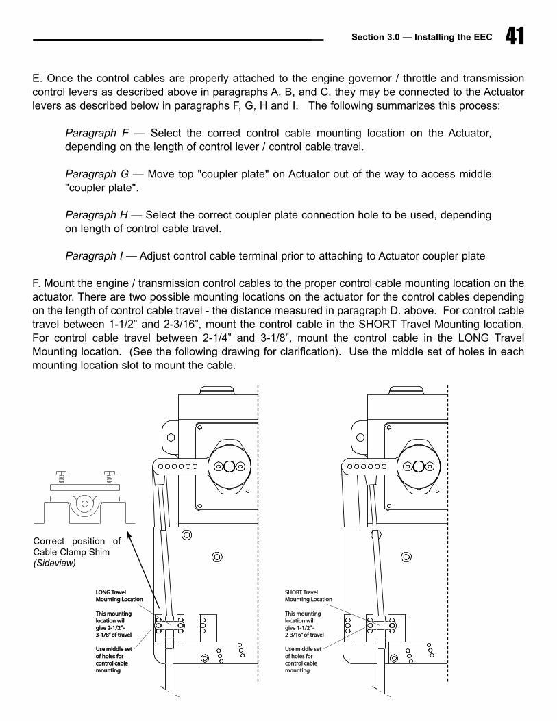
Section 3.0 — Installing the EEC 41
E. Once the control cables are properly attached to the engine governor / throttle and transmissioncontrol levers as described above in paragraphs A, B, and C, they may be connected to the Actuatorlevers as described below in paragraphs F, G, H and I. The following summarizes this process:
Paragraph F — Select the correct control cable mounting location on the Actuator,depending on the length of control lever / control cable travel.
Paragraph G — Move top "coupler plate" on Actuator out of the way to access middle"coupler plate".
Paragraph H — Select the correct coupler plate connection hole to be used, dependingon length of control cable travel.
Paragraph I — Adjust control cable terminal prior to attaching to Actuator coupler plate
F. Mount the engine / transmission control cables to the proper control cable mounting location on theactuator. There are two possible mounting locations on the actuator for the control cables dependingon the length of control cable travel - the distance measured in paragraph D. above. For control cabletravel between 1-1/2” and 2-3/16”, mount the control cable in the SHORT Travel Mounting location.For control cable travel between 2-1/4” and 3-1/8”, mount the control cable in the LONG TravelMounting location. (See the following drawing for clarification). Use the middle set of holes in eachmounting location slot to mount the cable.
LONG TravelLONG TravelMounting LocationMounting Location
This mountingThis mountinglocation willlocation will give 2-1/2” - give 2-1/2” - 3-1/8” of travel3-1/8” of travel
Use middle setUse middle setof holes forof holes forcontrol cablecontrol cablemountingmounting
SHORT TravelSHORT TravelMounting LocationMounting Location
This mountingThis mountinglocation willlocation will give 1-1/2” - give 1-1/2” - 2-3/16” of travel2-3/16” of travel
Use middle setUse middle setof holes forof holes forcontrol cablecontrol cablemountingmounting
Correct position ofCable Clamp Shim(Sideview)
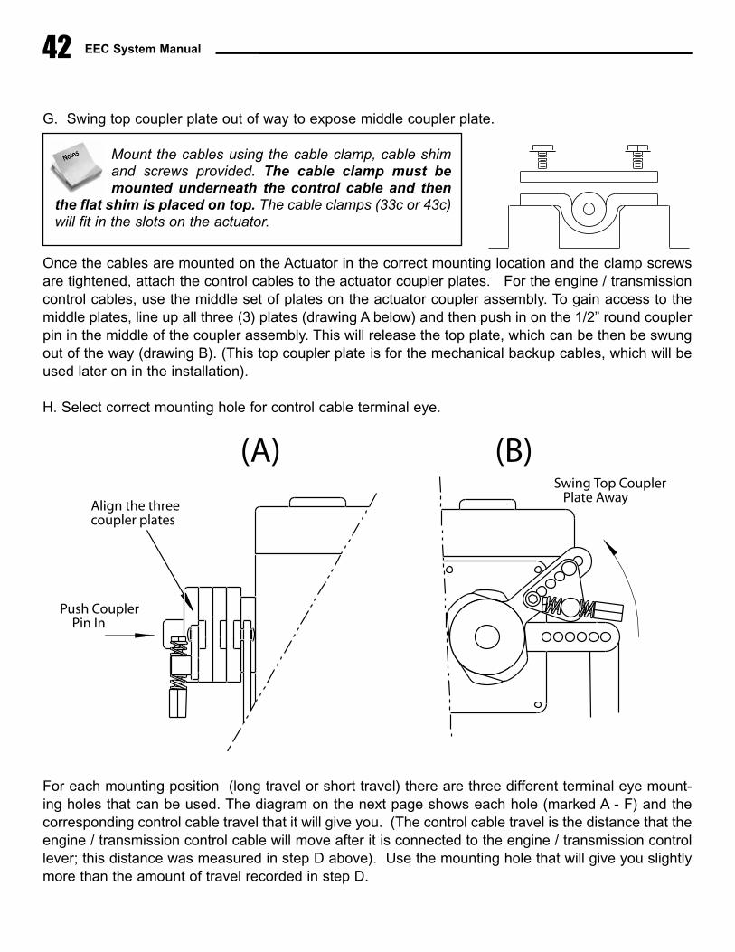
EEC System Manual
G. Swing top coupler plate out of way to expose middle coupler plate.
Once the cables are mounted on the Actuator in the correct mounting location and the clamp screwsare tightened, attach the control cables to the actuator coupler plates. For the engine / transmissioncontrol cables, use the middle set of plates on the actuator coupler assembly. To gain access to themiddle plates, line up all three (3) plates (drawing A below) and then push in on the 1/2” round couplerpin in the middle of the coupler assembly. This will release the top plate, which can be then be swungout of the way (drawing B). (This top coupler plate is for the mechanical backup cables, which will beused later on in the installation).
H. Select correct mounting hole for control cable terminal eye.
For each mounting position (long travel or short travel) there are three different terminal eye mount-ing holes that can be used. The diagram on the next page shows each hole (marked A - F) and thecorresponding control cable travel that it will give you. (The control cable travel is the distance that theengine / transmission control cable will move after it is connected to the engine / transmission controllever; this distance was measured in step D above). Use the mounting hole that will give you slightlymore than the amount of travel recorded in step D.
42
Mount the cables using the cable clamp, cable shimand screws provided. The cable clamp must bemounted underneath the control cable and then
the flat shim is placed on top. The cable clamps (33c or 43c)will fit in the slots on the actuator.
Push Coupler Pin In
Swing Top Coupler Plate Away
(A) (B)
Align the threecoupler plates
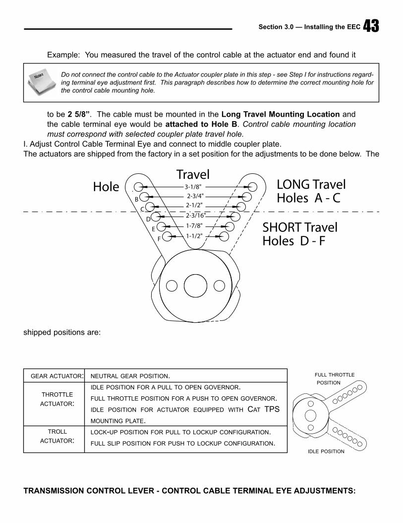
Section 3.0 — Installing the EEC 43
Example: You measured the travel of the control cable at the actuator end and found it
to be 2 5/8”. The cable must be mounted in the Long Travel Mounting Location andthe cable terminal eye would be attached to Hole B. Control cable mounting locationmust correspond with selected coupler plate travel hole.
I. Adjust Control Cable Terminal Eye and connect to middle coupler plate.The actuators are shipped from the factory in a set position for the adjustments to be done below. The
shipped positions are:
TRANSMISSION CONTROL LEVER - CONTROL CABLE TERMINAL EYE ADJUSTMENTS:
1-1/2"
1-7/8"
2-3/16"
2-1/2"
2-3/4"
3-1/8"A
B
C
D
E
F
HoleTravel
LONG TravelHoles A - C
SHORT TravelHoles D - F
Do not connect the control cable to the Actuator coupler plate in this step - see Step I for instructions regard-ing terminal eye adjustment first. This paragraph describes how to determine the correct mounting hole forthe control cable mounting hole.
GEAR ACTUATOR:
THROTTLE
ACTUATOR:
TROLL
ACTUATOR:
NEUTRAL GEAR POSITION.
IDLE POSITION FOR A PULL TO OPEN GOVERNOR.
FULL THROTTLE POSITION FOR A PUSH TO OPEN GOVERNOR.
IDLE POSITION FOR ACTUATOR EQUIPPED WITH CAT TPS
MOUNTING PLATE.
LOCK-UP POSITION FOR PULL TO LOCKUP CONFIGURATION.
FULL SLIP POSITION FOR PUSH TO LOCKUP CONFIGURATION.IDLE POSITION
FULL THROTTLE
POSITION
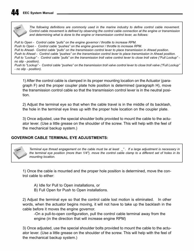
EEC System Manual44
1) After the control cable is clamped in its proper mounting location on the Actuator (para-graph F) and the proper coupler plate hole position is determined (paragraph H), movethe transmission control cable so that the transmission control lever is in the neutral posi-tion.
2) Adjust the terminal eye so that when the cable travel is in the middle of its backlash,the hole in the terminal eye lines up with the proper hole location on the coupler plate.
3) Once adjusted, use the special shoulder bolts provided to mount the cable to the actu-ator lever. (Use a little grease on the shoulder of the screw. This will help with the feel ofthe mechanical backup system.)
GOVERNOR CABLE TERMINAL EYE ADJUSTMENTS:
1) Once the cable is mounted and the proper hole position is determined, move the con-trol cable to either:
A) Idle for Pull to Open installations, or B) Full Open for Push to Open installations.
2) Adjust the terminal eye so that the control cable lost motion is eliminated. In otherwords, when the actuator begins moving, it will not have to take up the backlash in thecable before it moves the engine governor.
-On a pull-to-open configuration, pull the control cable terminal away from the engine (in the direction that will increase engine RPM)
3) Once adjusted, use the special shoulder bolts provided to mount the cable to the actu-ator lever. (Use a little grease on the shoulder of the screw. This will help with the feel ofthe mechanical backup system.)
The following definitions are commonly used in the marine industry to define control cable movement.Control cable movement is defined by observing the control cable connection at the engine or transmissionand determining what is done to the engine or transmission control lever, as follows:
Pull to Open - Control cable “pulls” on the engine governor / throttle to increase RPM.Push to Open - Control cable “pushes” on the engine governor / throttle to increase RPM.Pull to Ahead- Control cable “pulls” on the transmission control lever to place transmission in Ahead position.Push to Ahead - Control cable “pushes” on the transmission control lever to place transmission in Ahead position.Pull to “Lockup” - Control cable “pulls” on the transmission troll valve control lever to close troll valve (“Full Lockup” -no slip - position).Push to “Lockup” - Control cable “pushes” on the transmission troll valve control lever to close troll valve (“Full Lockup”- no slip - position).
Terminal eye thread engagement on the cable must be at least _” . If a large adjustment is necessary inthe terminal eye position (more than 1/4"), move the control cable clamp to a different set of holes in itsmounting location.

Section 3.0 — Installing the EEC 45
TROLL VALVE CABLE TERMINAL EYE ADJUSTMENTS:
1) Once the cable is mounted and the proper hole position is determined, move the con-trol cable to either:
C) “Lock up” for Pull to Lockup installations, or D) “Full slip” for Push to Lockup installations.
2) Adjust the terminal eye so that the control cable lost motion is eliminated. In otherwords, when the actuator begins moving, it will not have to take up the backlash in thecable before it moves the engine governor.
-On a pull-to-open configuration, pull the control cable terminal away from the transmission (in the direction that will move the troll valve toward the “lockup position)
3) Once adjusted, use the special shoulder bolts provided to mount the cable to the actu-ator lever. (Use a little grease on the shoulder of the screw. This will help with the feel ofthe mechanical backup system.)
I. After completion of all the control cable mounting and connections, tighten all control cable jam nuts,
mounting screws, and shoulder screws. Also, split all cotter pins on engine and transmission controllevers.
J. Do not connect mechanical backup cables to Actuator at this time. The best time to make this con-nection at the completion of system calibration (See Section 4.0)
Terminal eye thread engagement on the cable must be at least 1/4”. If a large adjustment is necessary inthe terminal eye position (more than 1/4"), move the control cable clamp to a different set of holes in itsmounting location
Terminal eye thread engagement on the cable must be at least 1/4”. If a large adjustment is necessary inthe terminal eye position (more than 1/4"), move the control cable clamp to a different set of holes in itsmounting location

EEC System Manual46
� Mounting the Engine Processor
A. Mounting Location — The engine processor can bemounted anywhere in the engine room, or outside the engineroom, as long as the 20' connection cable to each actuatorwill be able to reach the Engine Processor. (The 20' actua-tor connection cable cannot be extended). The engineprocessor should be reasonably accessible so that changesin DIP switch settings and inspection of the internal indicatorlights (LED's) may be performed. As with the actuator loca-tion, the engine processor should not be installed in adverselocations subject to saltwater exposure or excessive heat.
B. The engine processor should be mounted using 1/4"(7mm) machine bolts or lag screws. If using lag screws,screw length should be no less than 1” (25mm). If using machine bolts, lockwashers or locknuts mustbe used.
� Tachometer Senders / Mechanical Drive Adapters
The purpose of the tachometer sender is to provide RPM informa-tion to the EEC system. This information is used by the Systemduring engine synchronization. Installation of the tachometersenders is relatively straightforward. The following points shouldbe considered:
A. Only tachometer senders that are supplied by GMP are to beused with the EEC system.
B. On engines equipped with mechanical tachometer outlets, suchas Detroit Diesel, Caterpillar 3208, MAN, etc. the tach sendersmay be directly connected to the tachometer outlet on the engine. The tach senders that are suppliedby GMP are “in-line” senders; that is, they may be installed between the engine tachometer connec-tion and any other tachometer senders or tachometer drive cables that are attached to that tachome-ter connection.
C. On engines that are not equipped with a tach sender outlet, such as Volvo Diesel or any gasolineengine, a mechanical tachometer adapter will have to be used. See the back of the Installation Manual
The Engine Processor is essentially a digital computer, similar to those used in offices or at home. Althoughthe system has been carefully designed to operate in conditions that are common in recreational yachts.Reliability of the system will be enhanced if the engine processor can be mounted in an area external to theengine room, where operating temperatures will be somewhat cooler.
This end connectsto engine’s tach outlet
Section 3.0 — Installing the EEC 47
(Section 6.2) for a list of applicable drive adapters and drive adapter installation instructions.
D. The tach senders must be driven at a speed that corresponds to 1/2 engine speed. This is normalon most engines that have mechanical tachometer outlets or that use a mechanical drive adapter. Onsome engines, it may be possible to drive the tach sender at 1:1 or even twice engine speed. If thisis done, the Engine Processor will be damaged due to excessive voltage output from the tach sender.To check for excessive tach sender speed, set your meter on frequency or hertz, verify that at full openthe frequency is no larger than 5000 hz. (If you cannot check frequency , check the voltage from thetach sender while the engine is running at full speed. No more than 18 VAC should be present at thetachometer sender terminals.)
3.4 Engine Room Electrical ConnectionsAfter all of the EEC system mechanical components are correctly installed, the following electrical con-nections should be made.
� Actuator Harness
1) Each actuator is provided with a 20' harness, which electrically connects the Actuator to the EngineProcessor (EP). Route each harness, from the port and starboard Actuators, to enter the EngineProcessor at the front bottom. Route the harness alongside other cable or piping runs, avoidingsources of excessive heat. Securely fasten the harness using tie-wraps or cable clamps - DO NOTCOIL EXCESS HARNESS LENGTH.
2) Remove the tape from the connectors and wire terminals.
3) Attach the wire terminals to their respective terminal strips. Observe that wires are correctly con-nected to each screw connection following the color coding on the Engine Processor label. Securelytighten all of the barrier strip screws.
4) Plug in each actuator plug to its appropriate connection point. Once the connector is fully engaged,rotate the connector nut clockwise until a “detent” is felt. This will lock the connector in place.
5) Secure the actuator harness in the proper strain relief slot. The port actuator power and feedback
Make sure that the actuator power and feed back wires are installed in the correct location for the port andstarboard Actuator.
DO NOT FORCE CONNECTOR INTO RECEPTACLE - BE CERTAIN THAT THE CONNECTOR IS PROP-ERLY ALIGNED PRIOR TO PLUGGING IT IN! If the connector is properly aligned with its receptacle, onlya small amount of physical force will be necessary to insert connector into Engine Processor. Failure toproperly align the connector may damage it and cause the EEC system to fail.

EEC System Manual
wires go into the 1/2” slot on the left hand side of the EP and likewise the starboard actuator powerand feedback wires go into the _” slot on the right hand side of the EP. The middle 3/8” slots are forthe SP/EP connection cables. Install tie wraps around each wire and use the tie strap holder provided.NOTE: A LARGER WIRING DIAGRAM IS ENCLOSED IN THE BACK OF THIS MANUAL (PG. 102).
� Engine Processor (EP) Power Supply & Bonding Wire
1. Run #12 gage wire from two independent battery sources, normally the port and starboard enginestart batteries, to the EP. On the positive side of these two runs, install a 25amp circuit breaker neareach battery or power source. (Follow ABYC standards which requires a circuit protection device with-
48
STB���ACTUATORPower�Connection
STBACTUATORFEEDBACK
PORT�ACTUATORPower�Connection
FEEDBACK
PORTACTUATOR
STATION���CONNECTIONS
MAINS�1 S�2
S�3 S�4
S�5 S�6
Remote
Remote
Remote
Remote
Remote
Serial�#
Date
Voltage
GREEN
ORANGE
WHITEBLACKREDBLUE
GREENWHITEBLACK
REDBLUE
ORANGE
12/24v�D.C.�POWER�INPUT--++
Tachometer�Sender�InputsPORT STB
�STATION�PROCESSOR�
��STATION�PROCESSOR�
BATTERY(PORT)
BATTERY���(STB)
+
ENGINE��PROCESSOR
ACTUATOR���(PORT)
MAIN CONTROL STATION SECONDARY CONTROL STATIONS
Total�of�5�RemoteStations�Possible
BLACK�(12�AWG)*
RED�(12�AWG)*
Common DCground�point
CONTROL��HANDLECABLE��(6'�long)
ACTUATORCABLE�HARNESS
SP�/�EP CABLE(5'�-�100'�long���-�specify�length)
NOTES:
(use�18/2�awg��shielded�wire)�
�Supplied�with�Control�Head
���(20 '�long�supplied�with�Actuator)
BREAKER
NOTE4
25A
�DIP��SWITCHACCESS��COVER
Power�SwitchRelay�Box
Part�#�11700(optional)
EECPower�Switch���(optional)
+
Engine Processor 12/24v DC Troll Capable WIRING DIAGRAM Part # 11200-02T
BREAKER
25A
RED�(12�AWG)*
1.�All�connection�cables�supplied�by�GMP�are�pre-terminated�with�connectors.��Installer�will�supply�and�terminate:�Battery�Power�Wire,�Start-Interlock�Wire,�Tachometer�Wire, Power�Switch�Relay�Box�Wire�(optional)2.�Engine�processor,�Station�Processor,�Control�heads�and�optional�Power�Switch�Box�are�capable�of�operating�at�10v��-��30v�DC.�(Both�batteries�must�be�same�voltage.)�NOTE:�Actuators�must�be�ordered for�12v�or�24v�
�DC�operation.3.�Bonding�is�done�only�at�the�Engine�Processor.��All�other�components�are�already bonded�to�the�Engine�processor �(In�compliance�with:ABYC�#E-146&CFR�Code�111.05)4.�Use�12�awg.�wire.��When�D.�C.�power�input�wires�are�more�than�15�feet��in�length�up-grade�to�10�(awg)�wire.��(See�manual for�more�detail)5.�Station�Processor�is�NOT�needed�if�using�EEC-2001�style�Control�Head�or�Sidemount�Controls.
RUN
+
+RUN
STA
RT
STA
RT
(EXISTING�STARTER�SWITCHES)
(Other) (Other)
-�break�existing�wires�which�route�from�starter�switches���to�starter�relays�and�run�to�terminal�strip�on�each�Actautor.��Then�run��wires�to�starter�relays.
START�INTERLOCK�WIRINGSTARTER(PORT)
�STARTSOLENOID
(EXISTING�STARTER�RELAYS)
Tach�Sender(PORT)
Part�#�93111
BAT.�+
BLACKREDBLUEORANGE
FEEDBACK
���TROLLACTUATOR
ACTUATOR��(TROLL)����(optional)
���TROLLACTUATOR
PowerConnection
ACTUATOR�(STB)
Tach�Sender(STBD)
Part�#�93111
NOTE3
STARTER��(PORT)
�STARTSOLENOID
BAT.�+
Mechanical�/�Electronic��Control�Head
Electronic�only�Control�Head
WHITE
GREEN
NOTE5
The Glendinning EEC system is equipped with a sophisticated power management system that allows it toreceive power from 2 independent batteries (normally the port and starboard engine start batteries). In nor-mal operation, the EEC will receive power from both battery sources, taking power from each battery pro-portionate to the voltage level available. In the event of loss of power voltage from one battery source, such
as during engine start, the EEC system will continue to function normally by receiving power from the other battery withnormal voltage.
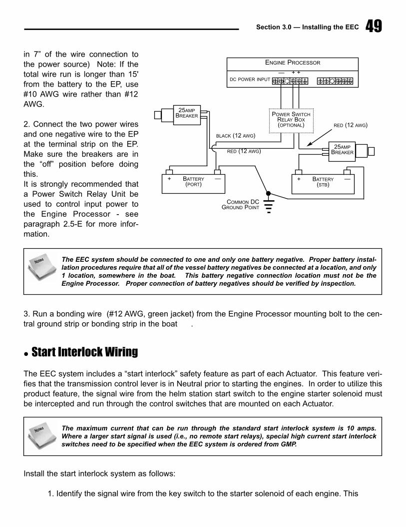
Section 3.0 — Installing the EEC 49
in 7” of the wire connection tothe power source) Note: If thetotal wire run is longer than 15'from the battery to the EP, use#10 AWG wire rather than #12AWG.
2. Connect the two power wiresand one negative wire to the EPat the terminal strip on the EP.Make sure the breakers are inthe “off” position before doingthis. It is strongly recommended thata Power Switch Relay Unit beused to control input power tothe Engine Processor - seeparagraph 2.5-E for more infor-mation.
3. Run a bonding wire (#12 AWG, green jacket) from the Engine Processor mounting bolt to the cen-tral ground strip or bonding strip in the boat .
� Start Interlock Wiring
The EEC system includes a “start interlock” safety feature as part of each Actuator. This feature veri-fies that the transmission control lever is in Neutral prior to starting the engines. In order to utilize thisproduct feature, the signal wire from the helm station start switch to the engine starter solenoid mustbe intercepted and run through the control switches that are mounted on each Actuator.
Install the start interlock system as follows:
1. Identify the signal wire from the key switch to the starter solenoid of each engine. This
The EEC system should be connected to one and only one battery negative. Proper battery instal-lation procedures require that all of the vessel battery negatives be connected at a location, and only1 location, somewhere in the boat. This battery negative connection location must not be theEngine Processor. Proper connection of battery negatives should be verified by inspection.
The maximum current that can be run through the standard start interlock system is 10 amps.Where a larger start signal is used (i.e., no remote start relays), special high current start interlockswitches need to be specified when the EEC system is ordered from GMP.
ENGINE PROCESSOR
DC POWER INPUT
RED (12 AWG)
RED (12 AWG)
BLACK (12 AWG)
— + +
POWER SWITCHRELAY BOX(OPTIONAL)
25AMPBREAKER
— + BATTERY(STB)
— + BATTERY(PORT)
25AMPBREAKER
COMMON DC GROUND POINT
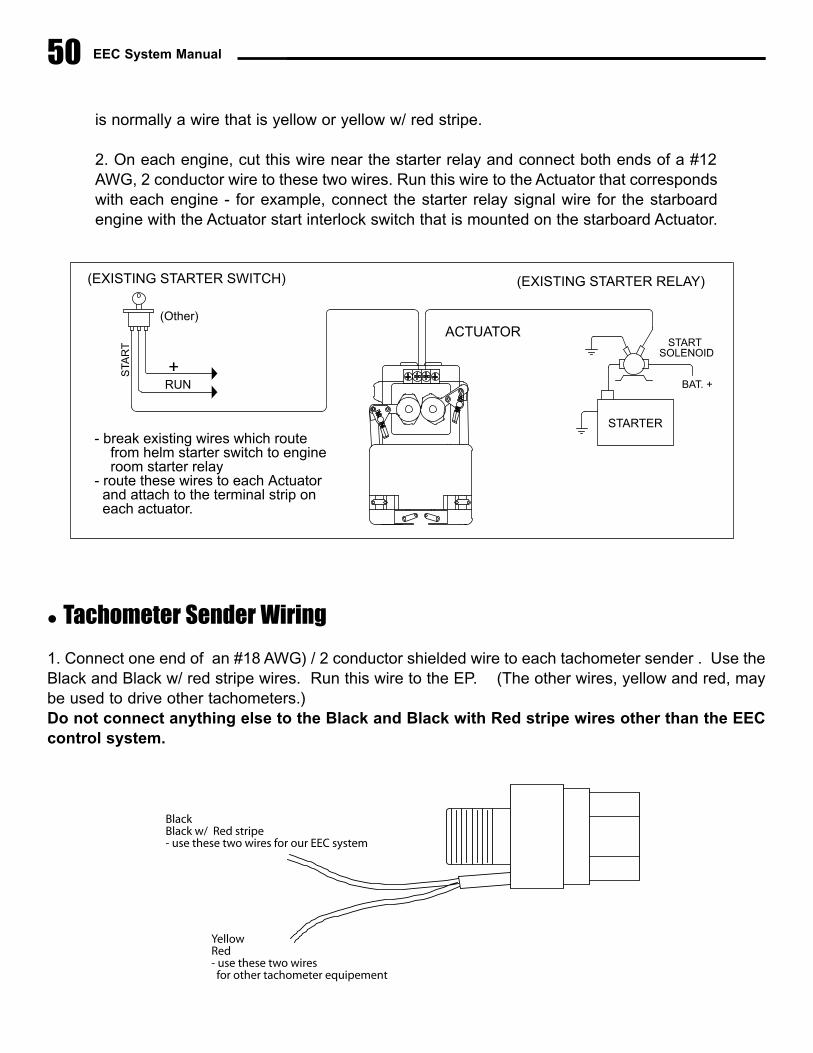
EEC System Manual50
is normally a wire that is yellow or yellow w/ red stripe.
2. On each engine, cut this wire near the starter relay and connect both ends of a #12AWG, 2 conductor wire to these two wires. Run this wire to the Actuator that correspondswith each engine - for example, connect the starter relay signal wire for the starboardengine with the Actuator start interlock switch that is mounted on the starboard Actuator.
� Tachometer Sender Wiring
1. Connect one end of an #18 AWG) / 2 conductor shielded wire to each tachometer sender . Use theBlack and Black w/ red stripe wires. Run this wire to the EP. (The other wires, yellow and red, maybe used to drive other tachometers.)Do not connect anything else to the Black and Black with Red stripe wires other than the EECcontrol system.
ACTUATOR
RUN
+
STA
RT
(EXISTING�STARTER�SWITCH)
(Other)
-�break�existing�wires�which�route�from�helm�starter�switch�to�engine�room�starter�relay
-�route�these�wires�to�each�Actuator��and�attach�to�the�terminal�strip�on��each�actuator.
STARTER
�STARTSOLENOID
(EXISTING�STARTER�RELAY)
BAT.�+
BlackBlack w/ Red stripe- use these two wires for our EEC system
YellowRed- use these two wires for other tachometer equipement
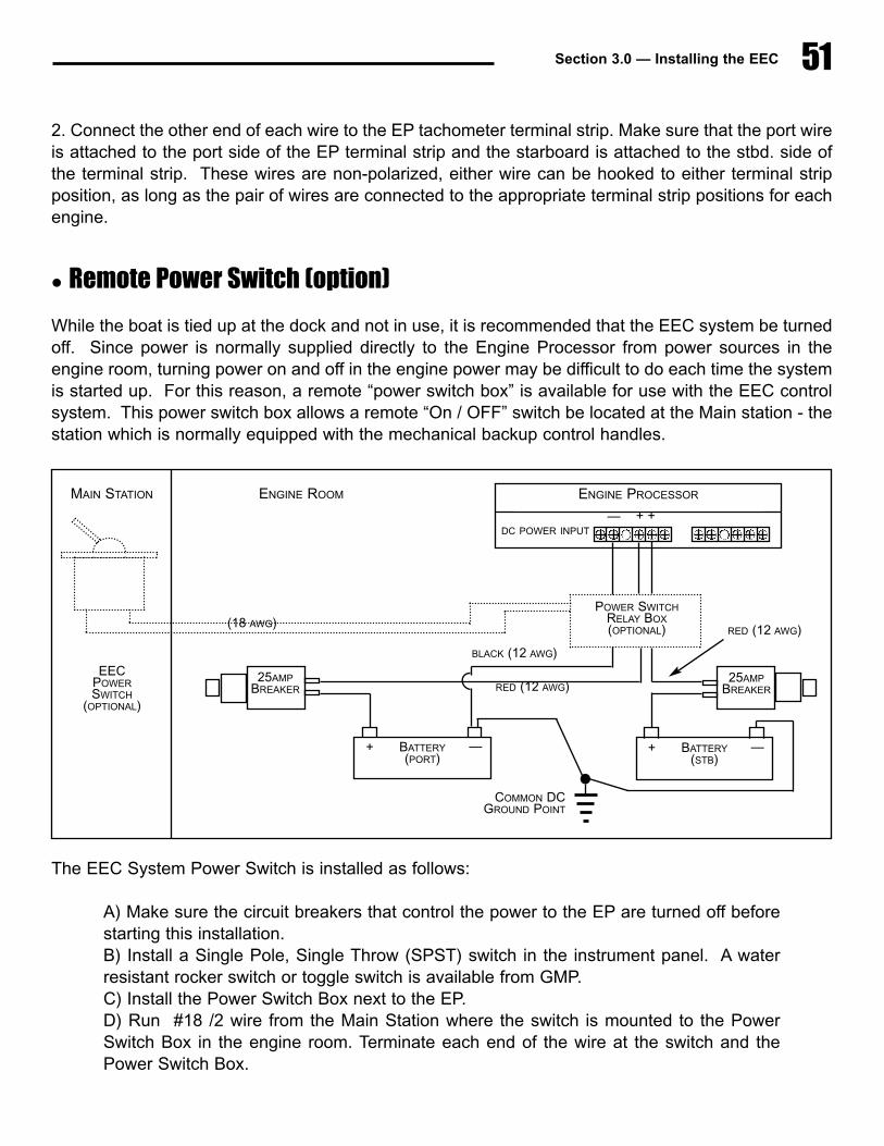
Section 3.0 — Installing the EEC 51
2. Connect the other end of each wire to the EP tachometer terminal strip. Make sure that the port wireis attached to the port side of the EP terminal strip and the starboard is attached to the stbd. side ofthe terminal strip. These wires are non-polarized, either wire can be hooked to either terminal stripposition, as long as the pair of wires are connected to the appropriate terminal strip positions for eachengine.
� Remote Power Switch (option)
While the boat is tied up at the dock and not in use, it is recommended that the EEC system be turnedoff. Since power is normally supplied directly to the Engine Processor from power sources in theengine room, turning power on and off in the engine power may be difficult to do each time the systemis started up. For this reason, a remote “power switch box” is available for use with the EEC controlsystem. This power switch box allows a remote “On / OFF” switch be located at the Main station - thestation which is normally equipped with the mechanical backup control handles.
The EEC System Power Switch is installed as follows:
A) Make sure the circuit breakers that control the power to the EP are turned off beforestarting this installation.B) Install a Single Pole, Single Throw (SPST) switch in the instrument panel. A waterresistant rocker switch or toggle switch is available from GMP.C) Install the Power Switch Box next to the EP. D) Run #18 /2 wire from the Main Station where the switch is mounted to the PowerSwitch Box in the engine room. Terminate each end of the wire at the switch and thePower Switch Box.
ENGINE PROCESSORENGINE ROOMMAIN STATION
DC POWER INPUT
RED (12 AWG)
RED (12 AWG)
(18 AWG)
BLACK (12 AWG)
— + +
POWER SWITCHRELAY BOX(OPTIONAL)
25AMPBREAKER
— + BATTERY(STB)
— + BATTERY(PORT)
25AMPBREAKER
EECPOWERSWITCH
(OPTIONAL)
COMMON DC GROUND POINT

EEC System Manual52
E) Attach the battery input power (2 positive wires / 1 negative wire) to the input side ofthe Power switch Box.F) Connect the output terminals of the Power switch Box - (2) positive and (1) negativeconnection - to the power input terminals of the Engine Processor.
3.5 Topside Component Installation� General Overview
A. The most important factor in selecting control head locations will obviously be the ability to controlthe vessel from the control station. In addition, the following factors should also be kept in mind:
1) Allowance for the full movement of the control head handles should be considered.Due to interference from other equipment mounted on the helm station control panel, itis possible that the normal movement of the control head is prevented at either end oftravel. THIS MUST NOT BE ALLOWED!
2) Although the control heads are sealed to prevent moisture from getting inside them,they are not designed to be submerged or allowed to remain in standing water for pro-longed periods. The area around the control head should have proper drainage.
B. In addition to the factors identified above for control head location, other factors should be consid-ered in selecting a location for the mechanical backup control head:
1) A mechanical backup interface assembly is mounted to the bottom of the mechanicalbackup control head. A minimum amount of space as shown below is required for thisinterface assembly.
2) The control cables that are connected to the mechanical backup interface will extenddownward from the assembly and should be routed with a minimum bend radius of 9inches.
3) The mechanical backup station should be located such that it is possible to maneuverand dock the boat from this station.
� Remote Station Control Head
The Remote Station Control Heads are the electric only heads. Follow the procedure below wheninstalling each control handle.
The following instructions describe the installation of the standard "Top Mount" Control Head. SeeSection 6.1 of this Installation Manual for information about the "Side Mount" control head.
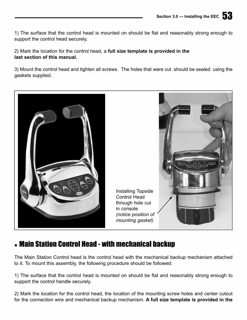
Section 3.0 — Installing the EEC 53
1) The surface that the control head is mounted on should be flat and reasonably strong enough tosupport the control head securely.
2) Mark the location for the control head, a full size template is provided in the last section of this manual.
3) Mount the control head and tighten all screws. The holes that were cut should be sealed using thegaskets supplied.
� Main Station Control Head - with mechanical backup
The Main Station Control head is the control head with the mechanical backup mechanism attachedto it. To mount this assembly, the following procedure should be followed:
1) The surface that the control head is mounted on should be flat and reasonably strong enough tosupport the control handle securely.
2) Mark the location for the control head, the location of the mounting screw holes and center cutoutfor the connection wire and mechanical backup mechanism. A full size template is provided in the
Installing TopsideControl Headthrough hole cutin console(notice position ofmounting gasket)
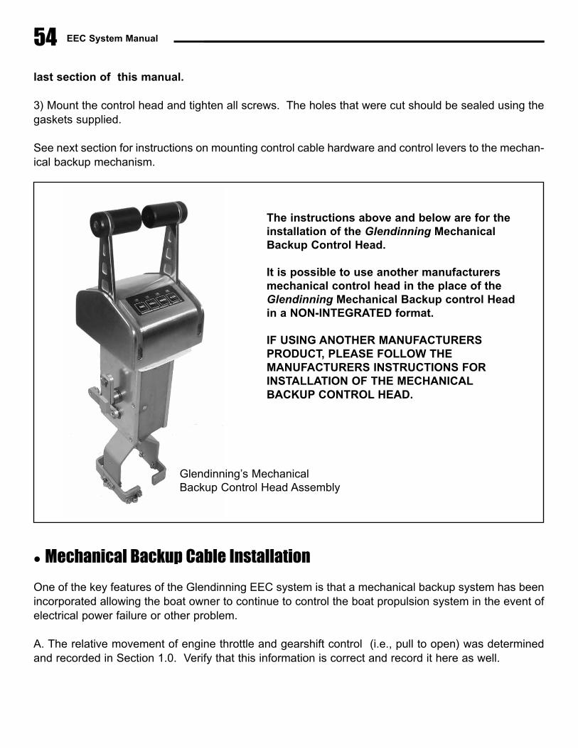
EEC System Manual54
last section of this manual.
3) Mount the control head and tighten all screws. The holes that were cut should be sealed using thegaskets supplied.
See next section for instructions on mounting control cable hardware and control levers to the mechan-ical backup mechanism.
� Mechanical Backup Cable Installation
One of the key features of the Glendinning EEC system is that a mechanical backup system has beenincorporated allowing the boat owner to continue to control the boat propulsion system in the event ofelectrical power failure or other problem.
A. The relative movement of engine throttle and gearshift control (i.e., pull to open) was determinedand recorded in Section 1.0. Verify that this information is correct and record it here as well.
The instructions above and below are for theinstallation of the Glendinning MechanicalBackup Control Head.
It is possible to use another manufacturersmechanical control head in the place of theGlendinning Mechanical Backup control Headin a NON-INTEGRATED format.
IF USING ANOTHER MANUFACTURERSPRODUCT, PLEASE FOLLOW THE MANUFACTURERS INSTRUCTIONS FORINSTALLATION OF THE MECHANICAL BACKUP CONTROL HEAD.
Glendinning’s Mechanical Backup Control Head Assembly
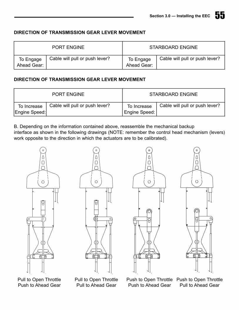
Section 3.0 — Installing the EEC 55
DIRECTION OF TRANSMISSION GEAR LEVER MOVEMENT
DIRECTION OF TRANSMISSION GEAR LEVER MOVEMENT
B. Depending on the information contained above, reassemble the mechanical backup interface as shown in the following drawings (NOTE: remember the control head mechanism (levers)work opposite to the direction in which the actuators are to be calibrated).
PORT ENGINE STARBOARD ENGINE
To Engage Ahead Gear:
Cable will pull or push lever? To Engage Ahead Gear:
Cable will pull or push lever?
PORT ENGINE STARBOARD ENGINE
To IncreaseEngine Speed:
Cable will pull or push lever? To IncreaseEngine Speed:
Cable will pull or push lever?
Pull to Open ThrottlePush to Ahead Gear
Push to Open ThrottlePush to Ahead Gear
Push to Open ThrottlePull to Ahead Gear
Pull to Open ThrottlePull to Ahead Gear

EEC System Manual56
C. Mount the throttle and gear control cables to the mechanical backup interface as shown above. Usethe middle set of holes provided at the bottom of the mechanical backup assembly for mounting thecontrol cable clamps. Verify that the slot on the end fitting of the control cable is mated correctly to thecontrol cable clamp.
D. Screw the terminal eyes on the end of each control cable, ensuring that the terminal eye has 1/2”of thread engagement. Attach the terminal eyes to the mechanical backup interface control leversusing the shoulder screws provided. Use grease on the shoulder of the screws to make the mechani-cal backup easier to move.
E. Route the control cables to each actuator in the engine room. Take note on port and starboard andwhich side of the actuator is the gear side and which side is the throttle side.
F. Mount the control cable to the actuator as shown in the drawing on page 41. Use the middle set ofholes provided.
G. Screw the cable end spring mechanism onto the end of the control cable, obtaining at least 1/4” ofthread engagement (7 turns).
H. Adjust the gear control backup cable as follows:
1) Verify the following: - transmission control lever is in the Neutral detent. - mechanical backup control head is in the Neutral detent.
2) Compare the relative position of the top coupler plate with the position of the middleand bottom plate. They should all line up at neutral. If not adjust the hex nut.
3) If hex nut does not have at least 1/4” of thread engagement then remount cable in theother set of mounting holes.
I. Attach the throttle control backup cable as follows:
1) Verify the following: - governor or throttle is at idle for pull to open and at full open for push to open. - mechanical backup control head is in the Neutral detent.
Be sure to connect the mechanical backup linkage exactly as directed in the preceeding drawings,using the electrical connection cable as a reference. Although it may seem that these connectionsare “backwards” from normal convention (i.e., on the left hand drawing throttle is set for “pull toopen” although it would appear to be “push to open”), this arrangement is necessary due to paral-
lel connection of cables at Actuator coupler plates.
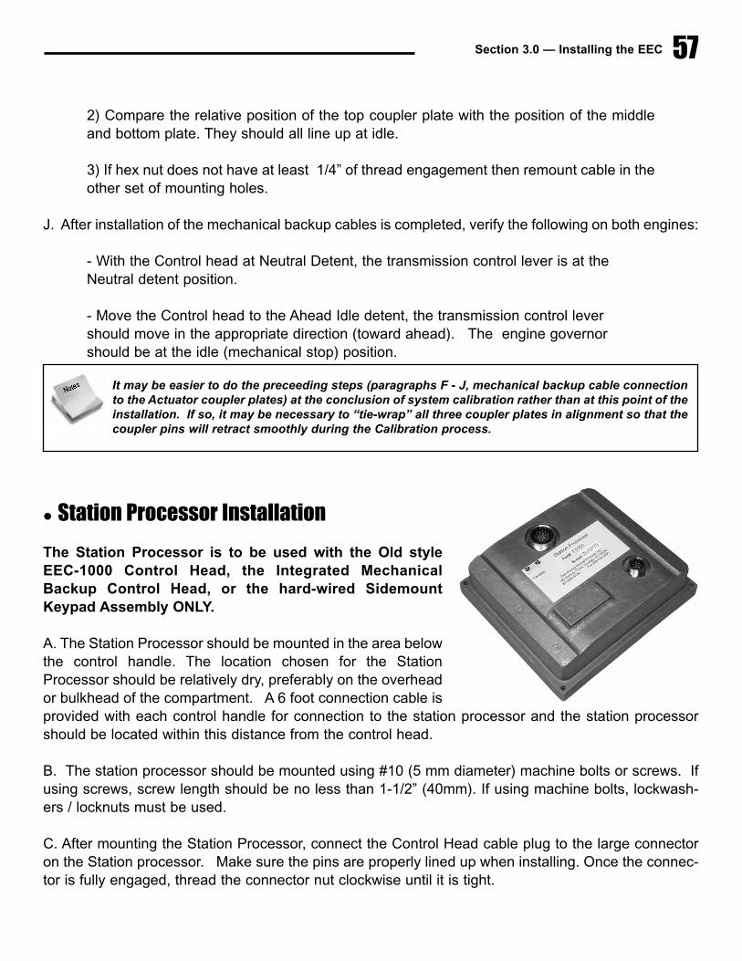
Section 3.0 — Installing the EEC 57
2) Compare the relative position of the top coupler plate with the position of the middleand bottom plate. They should all line up at idle.
3) If hex nut does not have at least 1/4” of thread engagement then remount cable in theother set of mounting holes.
J. After installation of the mechanical backup cables is completed, verify the following on both engines:
- With the Control head at Neutral Detent, the transmission control lever is at the Neutral detent position.
- Move the Control head to the Ahead Idle detent, the transmission control lever should move in the appropriate direction (toward ahead). The engine governor should be at the idle (mechanical stop) position.
� Station Processor Installation
The Station Processor is to be used with the Old styleEEC-1000 Control Head, the Integrated MechanicalBackup Control Head, or the hard-wired SidemountKeypad Assembly ONLY.
A. The Station Processor should be mounted in the area belowthe control handle. The location chosen for the StationProcessor should be relatively dry, preferably on the overheador bulkhead of the compartment. A 6 foot connection cable isprovided with each control handle for connection to the station processor and the station processorshould be located within this distance from the control head.
B. The station processor should be mounted using #10 (5 mm diameter) machine bolts or screws. Ifusing screws, screw length should be no less than 1-1/2” (40mm). If using machine bolts, lockwash-ers / locknuts must be used.
C. After mounting the Station Processor, connect the Control Head cable plug to the large connectoron the Station processor. Make sure the pins are properly lined up when installing. Once the connec-tor is fully engaged, thread the connector nut clockwise until it is tight.
It may be easier to do the preceeding steps (paragraphs F - J, mechanical backup cable connectionto the Actuator coupler plates) at the conclusion of system calibration rather than at this point of theinstallation. If so, it may be necessary to “tie-wrap” all three coupler plates in alignment so that thecoupler pins will retract smoothly during the Calibration process.
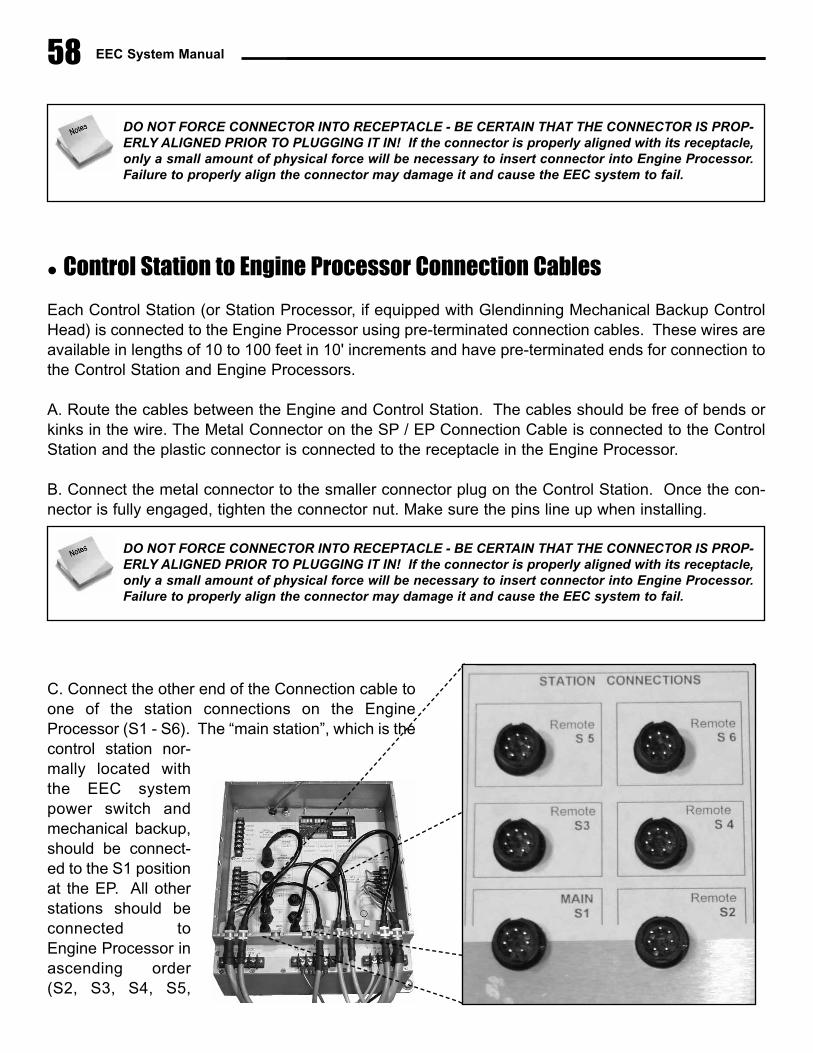
EEC System Manual
� Control Station to Engine Processor Connection Cables
Each Control Station (or Station Processor, if equipped with Glendinning Mechanical Backup ControlHead) is connected to the Engine Processor using pre-terminated connection cables. These wires areavailable in lengths of 10 to 100 feet in 10' increments and have pre-terminated ends for connection tothe Control Station and Engine Processors.
A. Route the cables between the Engine and Control Station. The cables should be free of bends orkinks in the wire. The Metal Connector on the SP / EP Connection Cable is connected to the ControlStation and the plastic connector is connected to the receptacle in the Engine Processor.
B. Connect the metal connector to the smaller connector plug on the Control Station. Once the con-nector is fully engaged, tighten the connector nut. Make sure the pins line up when installing.
C. Connect the other end of the Connection cable toone of the station connections on the EngineProcessor (S1 - S6). The “main station”, which is thecontrol station nor-mally located withthe EEC systempower switch andmechanical backup,should be connect-ed to the S1 positionat the EP. All otherstations should beconnected toEngine Processor inascending order(S2, S3, S4, S5,
58
DO NOT FORCE CONNECTOR INTO RECEPTACLE - BE CERTAIN THAT THE CONNECTOR IS PROP-ERLY ALIGNED PRIOR TO PLUGGING IT IN! If the connector is properly aligned with its receptacle,only a small amount of physical force will be necessary to insert connector into Engine Processor.Failure to properly align the connector may damage it and cause the EEC system to fail.
DO NOT FORCE CONNECTOR INTO RECEPTACLE - BE CERTAIN THAT THE CONNECTOR IS PROP-ERLY ALIGNED PRIOR TO PLUGGING IT IN! If the connector is properly aligned with its receptacle,only a small amount of physical force will be necessary to insert connector into Engine Processor.Failure to properly align the connector may damage it and cause the EEC system to fail.
S6). (Do not skip stations! - the Engine Processor will not “look” for a station connected to a higherstation connection point once it detects an empty connection receptacle). Once the cable connectoris fully engaged in its plug, rotate the connector nut clockwise until a “detent” is felt. This will lock theconnector in place. Make sure to line up the pins before inserting into the connector.
D. Mount the SP connection cables in smaller slots on the EP. Use the installed tie wrap holders toprovide proper strain relief to the connection cables. Fill up the extra slots with the plugs provided.
Section 3.0 — Installing the EEC 59
DO NOT FORCE CONNECTOR INTO RECEPTACLE - BE CERTAIN THAT THE CONNECTOR IS PROP-ERLY ALIGNED PRIOR TO PLUGGING IT IN! If the connector is properly aligned with its receptacle,only a small amount of physical force will be necessary to insert connector into Engine Processor.Failure to properly align the connector may damage it and cause the EEC system to fail.

60 EEC System Manual
61Section 4.0 — Maintenance
4.0 Maintenance
4.1 Routine MaintenanceThe EEC system has been designed to require as little maintenance as possible. In general, routinemaintenance consists of inspecting the system components for mechanical tightness and for indica-tions of external corrosion. This inspection should be done 2-3 times per season, perhaps at the begin-ning, middle, and end of each boating season.
System Component Description
Actuator a) Inspect external surfaces for corrosion, including actuator output shafts. Use “Corrosion Block” or equivalent to keep all Actuator surfaces free of corrosion.b) Verify that all control cable connections are tight. This includes:
—control cable clamps, which hold control cables onto Actuator—terminal eye jam nuts - small nuts on control cable rod end which lock terminal eye in place—“shoulder bolts” - bolts which attach control cables to Actuator coupler plates
Engine Processor a) Inspect external surfaces for corrosionb) Inspect wire connections for corrosion
Station Processor a) Inspect external surfaces for corrosion and free from moisture(if equipped) b) Verify that connectors are tight.
Control Head a) Inspect for visible moisture in control panel windows.
4.2 System Calibration CheckWhen the EEC system is initially installed in a boat, the system is calibrated to the limits of travel forengine governor and transmission control levers. As long as nothing is disturbed with the controlcables in the engine room, no re-calibration is necessary. However, during any routine work on the
If any welding is performed on the boat at any time, it is essential that the power input terminals andbonding system connection to the Engine Control System (EEC) must be disconnected from theEngine Processor. This is necessary to protect the system from any stray currents which may becreated during the process of welding. Failure to do this may cause damage to the EEC compo-
nents. This failure will not be covered by warranty!!!

62 EEC System Manual
engine governor or transmission, it is possible that these settings may be disturbed. If there is anypossibility that these control levers have been disturbed, the system calibration should be checked.
Recheck the system calibration using the following procedure:
1) Turn ON the EEC system (normal startup procedure - see Section 3.2).
2) Disconnect the control cable at the affected control lever - engine governor or transmission.(DO NOT disconnect the control cables at the EEC system actuators).
3) To check the transmission control cable calibration:
a) Place the Control Head in the Neutral detent position, and move the associated trans-mission control lever to it's Neutral detent. Verify that the control cable terminal eye isaligned with the control lever pivot pin.
b) Perform the same check with the Control head and transmission in the Ahead andAstern gear positions.
4) To check the engine governor control cable calibration:
a) With the Control Head in the Ahead idle detent position, and with the associatedengine governor lever at the idle mechanical stop, verify that the control cable terminaleye is aligned with the governor lever pivot pin.
b) Perform the same check with the Control head and engine governor in the FullThrottle positions.
If the terminal eyes DO NOT line up with the control lever pivot pins, the system must be re-calibrat-ed. (See Section 6.0 - System Calibration)
4.3 Actuator Control Cable ReplacementTo replace the control cables which connect the EEC Actuator to the engine / transmission controllevers, do the following:
1) Prior to removal of the existing control cable(s), verify that terminal eye locknuts are secure-ly fastened.
Failure to have gear actuator properly calibrated may lead to transmission failure. Always verify thatgear calibration is correct if any work is done on engine or transmission.

63Section 4.0 — Maintenance
2) Disconnect the control terminal eyes from the actuator coupler plate and governor / transmis-sion control levers. Remove the existing control cable from the actuator and control lever.
3) Loosen and unscrew the terminal eyes off the old control cable, counting the number of turns.Install the terminal eyes on the new control cable, screwing them on the same number of turns.
4) Mount the new control cable in the engine / transmission cable mounts. Mount the other endof the new control cable in the actuator mounting blocks. Ensure that the control cable slots fittightly on the cable clamps at both mounting positions.
5) Connect the terminal eyes to actuator coupler plate. Tighten the terminal eye locknuts.Secure the terminal eyes on the coupler plate pivots with cotter pins.
6) Verify that the terminal eyes have been correctly installed by verifying the system calibration(Paragraph 4.2). If the new control cable terminal eyes do not line up with engine / transmis-sion control levers, adjust the terminal eye position (screw on / off).
7) When the control cable terminal eyes are lined up, tighten the terminal eye locknut, andsecure the terminal eye on the engine / transmission control lever.

64 EEC System Manual

65Section 5.0 — System Calibration
5.0 System Calibration� Introduction
The purpose of EEC system calibration is to adjust the EEC system actuator movement (length of trav-el) so that it matches the movement of the engine governor lever, transmission gear selector lever, and/ or trolling valve control lever.
The EEC system must be calibrated after the system is installed, prior to initial operation. In addi-tion, the EEC system must be re-calibrated whenever any change is made in the control levers of theengine governor, reduction gear, or trolling valve. Re-calibration will be also be required if any changesare made to the push-pull control cables that connect each actuator to the engine governor and / orgear box.
� Calibration Procedure Overview
Calibration of the Electronic Engine Control system consists of manually controlling each actuatorthrough the complete range of travel of the associated engine or gear control lever . At each endpointof travel — engine throttle idle position, engine throttle full speed position, ahead gear position, asterngear position, etc. — the EEC system will “memorize” the location of this position and will use this posi-tion as a reference during operation. For example, during normal operation, when the vessel opera-tor moves the control head lever to the "idle, neutral" position, the EEC system will move the enginethrottle and gear control levers to the idle engine speed position and neutral gear position that wereset during the calibration procedure. Obviously, if this position is not correctly set during calibration,the EEC system will not be able to move the control levers to the correct position.
Manual calibration consists of 6 steps:
5.1 System preparation 5.4 Handle calibration5.2 Entering Calibration Mode 5.5 Exiting Calibration Mode5.3 Actuator positioning 5.6 Calibration verification
5.1 System PreparationPrior to beginning manual calibration, the EEC system must be prepared as follows:
1) BEFORE calibration, connect all push-pull control cables to the EEC actuators. AFTER calibrationyou may connect the other ends of the push-pull cables to the engine, transmission, and trolling valves.
Failure to recalibrate the EEC system after changes are made to engine and / or reduction gear con-trol levers, or the interconnecting push-pull cables, could cause failure of one or more system com-ponents.

66 EEC System Manual
Once calibration is completed, any changes that are made to the control cables or the engine / trans-mission control levers will make re-calibration of the EEC system necessary.
2) Verify that the Main station control handles are in the neutral position. The Main Station is the con-trol station that is connected to the "S1" connection in the Engine Processor. Normally, the Main sta-tion is also equipped with the mechanical backup cables.
3) Turn OFF all power to the EEC system.
4) Open the Engine Processor (EP) access plate to expose the DIP Switches and LED indicator lightassembly (see illustration below).
There are 2 separate calibration steps:
1) System Configuration — This sets the number of control stations, the direction of actuator travelfor throttle, gear and troll (if equipped).
2) Actuator Endpoint Positioning — This sets the position of the actuator endpoints.
� System Configuration
To set System Configurations you will be following the 4 steps outlined below for each System
Although the mechanical backup control cables may be hooked up (the cables which connect theEEC actuators to the mechanical backup control head), it may be easier to go through the calibra-tion process with these cables disconnected at the actuator. These control cables can be safelyhooked up after the calibration process is completed. This only applies to initial calibrations, before
the mechanical backup cables have been adjusted. During subsequent calibrations, the mechanical backupcables may be left connected to the actuator.
Engine Processor
“LO” EpromSerial Number
“HI” EpromSerial Number
These two lights are constantly litwhen EEC system is in operation.
Top
Bottom
LED Display8 7 6 5 4 3 2 1
SwitchBank 1
SwitchBank 2
Switch inON position
Switch inOFF position
To set the switch position, push down on the side of theswitch that is marked with your desired setting.Example, Push down on the OFF side if you want theswitch to be in the OFF position (see diagram above).
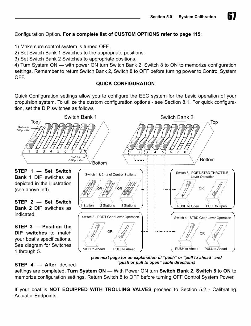
67Section 5.0 — System Calibration
Configuration Option. For a complete list of CUSTOM OPTIONS refer to page 115:
1) Make sure control system is turned OFF.2) Set Switch Bank 1 Switches to the appropriate positions.3) Set Switch Bank 2 Switches to appropriate positions.4) Turn System ON — with power ON turn Switch Bank 2, Switch 8 to ON to memorize configurationsettings. Remember to return Switch Bank 2, Switch 8 to OFF before turning power to Control SystemOFF.
QUICK CONFIGURATION
Quick Configuration settings allow you to configure the EEC system for the basic operation of yourpropulsion system. To utilize the custom configuration options - see Section 8.1. For quick configura-tion, set the DIP switches as follows
STEP 4 — After desiredsettings are completed, Turn System ON — With Power ON turn Switch Bank 2, Switch 8 to ON tomemorize configuration settings. Return Switch 8 to OFF before turning OFF Control System Power.
If your boat is NOT EQUIPPED WITH TROLLING VALVES proceed to Section 5.2 - CalibratingActuator Endpoints.
Switch�Bank�2Top
Bottom
6 7 8
1 2
1�Station
1 2
2�Stations
1 2
3�Stations
Switch�1�&�2�-�#�of�Control�Stations
OR OR
PUSH�to�Ahead
Switch�3�-�PORT�Gear�Lever�Operation
3
PULL�to�Ahead
OR
3
PUSH�to�Ahead
Switch�4�-�STBD�Gear�Lever�Operation
4
PULL�to�Ahead
OR
4
PUSH�to�Open
Switch�5�-�PORT/STBD�THROTTLE�Lever�Operation
5
PULL�to�Open
OR
5
1 2 3 4 5
Switch�Bank�1
1 2 3 4 5 6 7 8
Top
Bottom
Switch�inON�position
Switch�inOFF�position
STEP 1 — Set SwitchBank 1 DIP swtiches asdepicted in the illustration(see above left).
STEP 2 — Set SwitchBank 2 DIP switches asindicated.
STEP 3 — Position theDIP switches to matchyour boat’s specifications.See diagram for Switches1 through 5.
(see next page for an explanation of “push” or “pull to ahead” and “push or pull to open” cable directions)
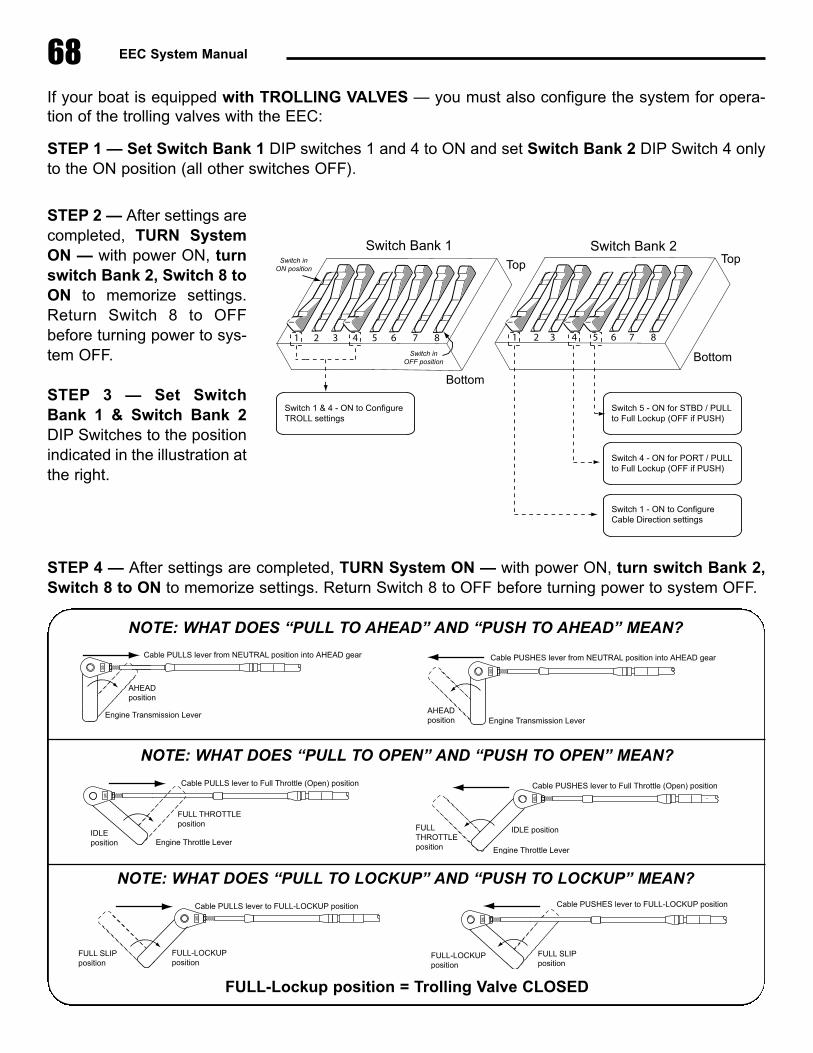
68 EEC System Manual
If your boat is equipped with TROLLING VALVES — you must also configure the system for opera-tion of the trolling valves with the EEC:
STEP 1 — Set Switch Bank 1 DIP switches 1 and 4 to ON and set Switch Bank 2 DIP Switch 4 onlyto the ON position (all other switches OFF).
STEP 4 — After settings are completed, TURN System ON — with power ON, turn switch Bank 2,Switch 8 to ON to memorize settings. Return Switch 8 to OFF before turning power to system OFF.
Switch�Bank�2Top
Bottom
6 7 8
Switch�1�&�4�-�ON�to�Configure�TROLL�settings
Switch�Bank�1
2 3 5 6 7 8
Top
Bottom
Switch�inON�position
Switch�inOFF�position
1 4
Switch�5�-�ON�for�STBD�/�PULL�to�Full�Lockup�(OFF�if�PUSH)
Switch�4�-�ON�for�PORT�/�PULLto�Full�Lockup�(OFF�if�PUSH)
Switch�1�-�ON�to�Configure�Cable�Direction�settings
2 31 4 5
FULL-LOCKUPposition
Cable�PULLS�lever�to�FULL-LOCKUP�position
FULL�SLIPposition
Cable�PUSHES�lever�to�FULL-LOCKUP�position
FULL�SLIP�position
FULL-LOCKUPposition
NOTE: WHAT DOES “PULL TO LOCKUP” AND “PUSH TO LOCKUP” MEAN?
Engine�Transmission�Lever
Cable�PULLS�lever�from�NEUTRAL�position�into�AHEAD�gear
AHEAD�position
Engine�Transmission�Lever
Cable�PUSHES�lever�from�NEUTRAL�position�into�AHEAD�gear
AHEAD�position
NOTE: WHAT DOES “PULL TO AHEAD” AND “PUSH TO AHEAD” MEAN?
Engine�Throttle�Lever
Cable�PULLS�lever�to�Full�Throttle�(Open)�position
IDLE�position
FULL�THROTTLEposition
Engine�Throttle�Lever
Cable�PUSHES�lever�to�Full�Throttle�(Open)�position
IDLE�positionFULLTHROTTLE�position
NOTE: WHAT DOES “PULL TO OPEN” AND “PUSH TO OPEN” MEAN?
FULL-Lockup position = Trolling Valve CLOSED
STEP 2 — After settings arecompleted, TURN SystemON — with power ON, turnswitch Bank 2, Switch 8 toON to memorize settings.Return Switch 8 to OFFbefore turning power to sys-tem OFF.
STEP 3 — Set SwitchBank 1 & Switch Bank 2DIP Switches to the positionindicated in the illustration atthe right.
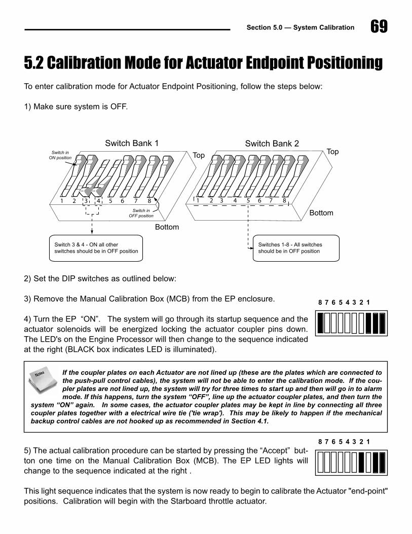
5.2 Calibration Mode for Actuator Endpoint PositioningTo enter calibration mode for Actuator Endpoint Positioning, follow the steps below:
1) Make sure system is OFF.
2) Set the DIP switches as outlined below:
3) Remove the Manual Calibration Box (MCB) from the EP enclosure.
4) Turn the EP “ON”. The system will go through its startup sequence and theactuator solenoids will be energized locking the actuator coupler pins down.The LED's on the Engine Processor will then change to the sequence indicatedat the right (BLACK box indicates LED is illuminated).
5) The actual calibration procedure can be started by pressing the “Accept” but-ton one time on the Manual Calibration Box (MCB). The EP LED lights willchange to the sequence indicated at the right .
This light sequence indicates that the system is now ready to begin to calibrate the Actuator "end-point"positions. Calibration will begin with the Starboard throttle actuator.
69Section 5.0 — System Calibration
8 7 6 5 4 3 2 1
8 7 6 5 4 3 2 1
If the coupler plates on each Actuator are not lined up (these are the plates which are connected tothe push-pull control cables), the system will not be able to enter the calibration mode. If the cou-pler plates are not lined up, the system will try for three times to start up and then will go in to alarmmode. If this happens, turn the system “OFF”, line up the actuator coupler plates, and then turn the
system “ON” again. In some cases, the actuator coupler plates may be kept in line by connecting all threecoupler plates together with a electrical wire tie ('tie wrap'). This may be likely to happen if the mechanicalbackup control cables are not hooked up as recommended in Section 4.1.
Switch�Bank�2Top
Bottom
6 7 8
Switch�3�&�4�-�ON�all�other�switches�should�be�in�OFF�position
Switch�Bank�1
2 3 5 6 7 8
Top
Bottom
Switch�inON�position
Switch�inOFF�position
1 4
Switches�1-8�-�All�switches�should�be�in�OFF�position
2 31 4 5
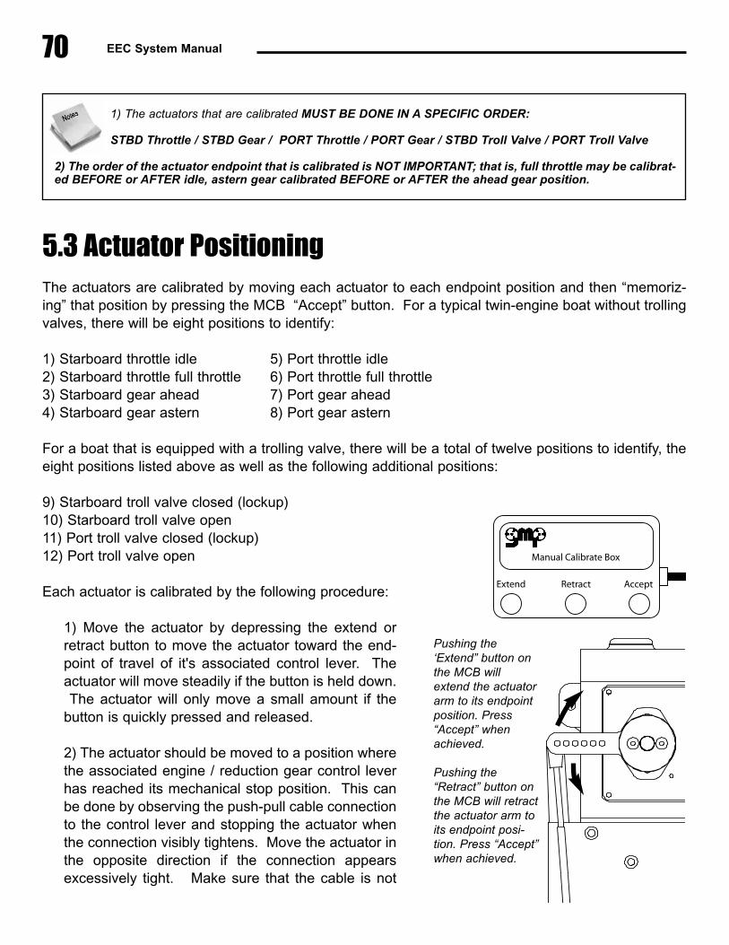
70 EEC System Manual
5.3 Actuator PositioningThe actuators are calibrated by moving each actuator to each endpoint position and then “memoriz-ing” that position by pressing the MCB “Accept” button. For a typical twin-engine boat without trollingvalves, there will be eight positions to identify:
1) Starboard throttle idle 5) Port throttle idle2) Starboard throttle full throttle 6) Port throttle full throttle3) Starboard gear ahead 7) Port gear ahead4) Starboard gear astern 8) Port gear astern
For a boat that is equipped with a trolling valve, there will be a total of twelve positions to identify, theeight positions listed above as well as the following additional positions:
9) Starboard troll valve closed (lockup)10) Starboard troll valve open11) Port troll valve closed (lockup)12) Port troll valve open
Each actuator is calibrated by the following procedure:
1) Move the actuator by depressing the extend orretract button to move the actuator toward the end-point of travel of it's associated control lever. Theactuator will move steadily if the button is held down.The actuator will only move a small amount if the
button is quickly pressed and released.
2) The actuator should be moved to a position wherethe associated engine / reduction gear control leverhas reached its mechanical stop position. This canbe done by observing the push-pull cable connectionto the control lever and stopping the actuator whenthe connection visibly tightens. Move the actuator inthe opposite direction if the connection appearsexcessively tight. Make sure that the cable is not
1) The actuators that are calibrated MUST BE DONE IN A SPECIFIC ORDER:
STBD Throttle / STBD Gear / PORT Throttle / PORT Gear / STBD Troll Valve / PORT Troll Valve
2) The order of the actuator endpoint that is calibrated is NOT IMPORTANT; that is, full throttle may be calibrat-ed BEFORE or AFTER idle, astern gear calibrated BEFORE or AFTER the ahead gear position.
LONG TravelMounting Location
This mountinglocation will give 2-1/2” - 3-1/8” of travel
Use middle setof holes forcontrol cablemounting
SHORT TravelMounting Location
This mountinglocation will give 1-1/2” - 2-3/16” of travel
Use middle setof holes forcontrol cablemounting
Extend Retract Accept
Manual Calibrate Box
Pushing the‘Extend” button onthe MCB willextend the actuatorarm to its endpointposition. Press“Accept” whenachieved.
Pushing the“Retract” button onthe MCB will retractthe actuator arm toits endpoint posi-tion. Press “Accept”when achieved.

71Section 5.0 — System Calibration
binding. It is important to find the proper balance between the control cable position being "tooloose" and not reaching its endpoint position (and therefore the engine not achieving idle speedor full throttle), and the cable being set up "too tight" and constantly operating in a compressedor stretched condition when moving to its endpoint of travel. Continue adjusting the actuatorposition until a good position has been achieved.
3) When the control lever endpoint is properly achieved, the position can be “memorized” bypressing the MCB “Accept” button (1 time).
4) Move the actuator in the opposite direction to calibrate the other endpoint of the controllever. Again, observe the push-pull cable connection and move the actuator to the pointwhere the lever is hard against its mechanical stop, but not binding.
5) When the control lever endpoint is properly achieved, the position should be “memorized”by pressing the MCB “Accept” button.
6) After both endpoints have been calibrated, press the “Accept” button one additional time tocalibrate the next actuator calibration position - see the order of calibration specified on theopposite page.
7) Once both endpoints of the final actuator have been "memorized" - either the port gear actu-ator or the port troll valve actuator - the "Accept" button must be pressed one additional time.This will confirm that all Actuators have been successfully calibrated, all of the endpoint posi-tions (engine idle, engine full throttle, etc.) have been stored in memory, and you are now readyto move to Handle Calibration.
LED Light Sequence
As an aid to the technician, the LEDs located in the EP access port will light up indicating the specif-ic Actuator that is currently being calibrated, and whether both endpoints have been calibrated. TheLEDs will light up according to the following sequence:
After system startup / prior to beginning calibrationLED 1 and 8 are ON (rightmost (2) LEDs are always ON when EEC system is operational).
(see more LED light sequences on next page)
It is important to note that the Actuators will move to the "mid-stroke" position when calibration iscomplete. If the Actuators do not move, it is possible that an error has been made during the cali-bration process:- The "Accept" button was not pressed one additional time, as described in Paragraph 7 above.
- Troll Valve Operation is set, but no Troll Valve actuators are installed.
8 7 6 5 4 3 2 1
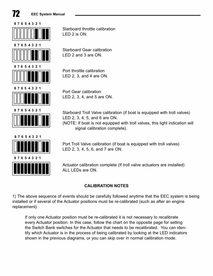
72 EEC System Manual
Starboard throttle calibrationLED 2 is ON.
Starboard Gear calibration LED 2 and 3 are ON.
Port throttle calibration LED 2, 3, and 4 are ON.
Port Gear calibrationLED 2, 3, 4, and 5 are ON.
Starboard Troll Valve calibration (if boat is equipped with troll valves)LED 2, 3, 4, 5, and 6 are ON.(NOTE: If boat is not equipped with troll valves, this light indication will
signal calibration complete).
Port Troll Valve calibration (if boat is equipped with troll valves)LED 2, 3, 4, 5, 6, and 7 are ON.
Actuator calibration complete (If troll valve actuators are installed)ALL LEDs are ON.
CALIBRATION NOTES
1) The above sequence of events should be carefully followed anytime that the EEC system is beinginstalled or if several of the Actuator positions must be re-calibrated (such as after an enginereplacement).
If only one Actuator position must be re-calibrated it is not necessary to recalibrateevery Actuator position. In this case, follow the chart on the opposite page for settingthe Switch Bank switches for the Actuator that needs to be recalibrated. You can iden-tify which Actuator is in the process of being calibrated by looking at the LED indicatorsshown in the previous diagrams, or you can skip over in normal calibration mode.
8 7 6 5 4 3 2 1
8 7 6 5 4 3 2 1
8 7 6 5 4 3 2 1
8 7 6 5 4 3 2 1
8 7 6 5 4 3 2 1
8 7 6 5 4 3 2 1
8 7 6 5 4 3 2 1
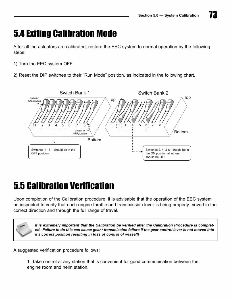
73Section 5.0 — System Calibration
5.4 Exiting Calibration ModeAfter all the actuators are calibrated, restore the EEC system to normal operation by the followingsteps:
1) Turn the EEC system OFF.
2) Reset the DIP switches to their “Run Mode” position, as indicated in the following chart.
5.5 Calibration VerificationUpon completion of the Calibration procedure, it is advisable that the operation of the EEC systembe inspected to verify that each engine throttle and transmission lever is being properly moved in thecorrect direction and through the full range of travel.
A suggested verification procedure follows:
1. Take control at any station that is convenient for good communication between theengine room and helm station.
Switch�Bank�2Top
Bottom
6 7 8
Switches�1�-�8��-�should�be�in�theOFF�position
Switch�Bank�1
2 3 5 6 7 8
Top
Bottom
Switch�inON�position
Switch�inOFF�position
1 4
Switches�2,�4,�&�6�-�should�be�in�the�ON�position�all�others�should�be�OFF
2 31 4 5
It is extremely important that the Calibration be verified after the Calibration Procedure is complet-ed. Failure to do this can cause gear / transmission failure if the gear control lever is not moved intoit's correct position resulting in loss of control of vessel!!
74 EEC System Manual
2. With the station control levers (port and starboard) in the neutral position, verify thefollowing for both engines and transmissions:
Engine governor - Idle position (mechanical stop)Gear control lever - Neutral positionTrolling valve - Lockup position (troll valve closed) (if installed)
3. Move the station control levers (port and starboard) to the ahead detent position.Verify that both gear control levers have moved to the ahead position and that thecontrol cable is not binding.
4. Move the station control lever (port and starboard) to the astern detent position.Verify that both transmission levers have moved to the astern position and that thecontrol cable is not binding.
5. Move the station control lever (port and starboard) to the full astern position.Verify that both engine governors are at the full throttle (mechanical stop) position andthat the control cable is not binding.
6. Move the station control lever (port and starboard) to the neutral position. Verifythat both engine governors are at the idle (mechanical stop) position and that thecontrol cable is not binding.
7. (Troll valve equipped boats only) - Move the station control lever (port and starboard)to the neutral position. Press and release the troll switch on the control. Troll switchlight will illuminate indicating that troll mode is energized. Verify that both troll actuatorshave moved to troll valve open position and that the control cable is not binding.
8. (Troll valve equipped boats only) - Move the station control lever (port and starboard)to the full throttle position. Verify that both troll actuators have moved toward lockupposition, but have not moved into the detented lock-up position and that the controlcable is not binding.
9. (Troll valve equipped boats only) - Move the station control lever (port and starboard)to the neutral position. Press and release the troll switch on the control. Troll switchlight will go out indicating that troll mode is off and that normal gear / throttle operationis available.. Verify that both troll actuators have returned to the lockup position and
The following points should be kept in mind when verifying actuator position and operation:Direction of travel - The location of engine idle and full throttle, gear ahead and astern, and troll valvelockup / slip should be considered to ensure that the EEC actuator is moving the engine and gearcontrols in the appropriate direction.
Actuator endpoint - The actuator should move its associated control lever to the mechanical stop without plac-ing undue strain on the control cable or control lever.Control lever detent position - When position the gear lever or trolling valve lever, it may be helpful to discon-nect the push-pull cable from the lever and move the control lever independently from the EEC system.

Section 5.0 — System Calibration 75
that the control cable is not binding.
After performing the Calibration Verification check, if you find that one actuator position needs to bechanged, go back to the beginning of the Calibration section and follow the instructions. You can skipover actuator positions just by pressing the “Accept” button. When skipping, watch the LED's. Thiswill let you know which actuator position you are at.
This completes the calibration procedure. The electronic engine control system is now fully opera-tional and ready for use.

76 EEC System Manual

77Section 6.0 — System Test & Checkout
6.0 System Test & Checkout� General Overview
System Inspection / Checkout consists of 2 steps:
a) Component Installation Checks - verify that the components are correctly mountedand installed.b) Operational Tests.
6.1 Component Installation Checks1. Engine Processor (Internal)
1.1 Before closing DIP Switch Access cover, verify that DIPswitches are correctly setfor:
—Correct synchronizer gain setting (Bank 1, Switches 5-8)—Selected gear delay (Bank 2, Switches 1-3)—Selected throttle delay (Bank 2, Switches 5 - 6)—EP is in Run mode (Bank 2, Switch 4 and Switch 8 = OFF)
After switch settings are verified to be correct, close DIP Switch Access cover andtighten (4) wing nuts.
1.2 Inside wire connection “cavity”, verify that all actuator power wires are properlyconnected to correct barrier strip terminal - verify jacket insulation color - and aretight. Verify that actuator feedback plugs are fully inserted and plug nuts aresecurely tightened (fully clockwise). Feel for click, do not overtighten.
1.3 Verify that all connection wires bushings are fitted into correct groove in EngineProcessor. All wires should be secured with tie-wraps.
1.4 Close Engine Processor cover.
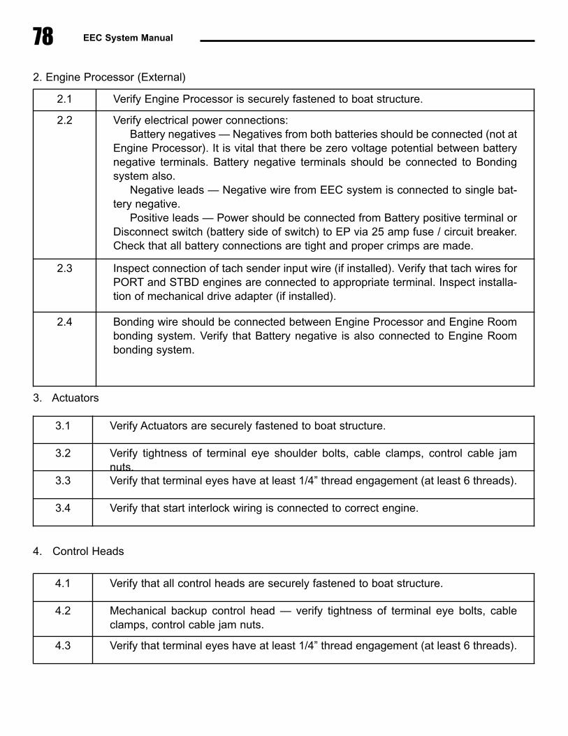
78 EEC System Manual
2. Engine Processor (External)
3. Actuators
4. Control Heads
2.1 Verify Engine Processor is securely fastened to boat structure.
2.2 Verify electrical power connections:Battery negatives — Negatives from both batteries should be connected (not at
Engine Processor). It is vital that there be zero voltage potential between batterynegative terminals. Battery negative terminals should be connected to Bondingsystem also.
Negative leads — Negative wire from EEC system is connected to single bat-tery negative.
Positive leads — Power should be connected from Battery positive terminal orDisconnect switch (battery side of switch) to EP via 25 amp fuse / circuit breaker.Check that all battery connections are tight and proper crimps are made.
2.3 Inspect connection of tach sender input wire (if installed). Verify that tach wires forPORT and STBD engines are connected to appropriate terminal. Inspect installa-tion of mechanical drive adapter (if installed).
2.4 Bonding wire should be connected between Engine Processor and Engine Roombonding system. Verify that Battery negative is also connected to Engine Roombonding system.
3.1 Verify Actuators are securely fastened to boat structure.
3.2 Verify tightness of terminal eye shoulder bolts, cable clamps, control cable jamnuts.
3.3 Verify that terminal eyes have at least 1/4” thread engagement (at least 6 threads).
3.4 Verify that start interlock wiring is connected to correct engine.
4.1 Verify that all control heads are securely fastened to boat structure.
4.2 Mechanical backup control head — verify tightness of terminal eye bolts, cableclamps, control cable jam nuts.
4.3 Verify that terminal eyes have at least 1/4” thread engagement (at least 6 threads).

79Section 6.0 — System Test & Checkout
5. Station Processor
6.2 Operational Checks
6.3 System Inspection / CheckoutThe Electronic Engine Control is a relatively complex system that has components located throughoutthe boat. Although efforts have been made to make the system reasonably easy to install, it is vitalthat the control system be thoroughly checked out prior to initial operation in order to verify that the
5.1 Verify that SP / EP cable and Control Head cable metal plug nuts are securelytightened (fully clockwise).
1 Prior to startup, verify that system has been calibrated (system must be calibratedprior to running).
2 If system has been calibrated, do the following:—Verify EEC power switch at main helm station is OFF.—Turn ON engine room circuit breakers to EEC system.—Power up EEC system as per normal procedure.
3 Perform calibration verification:a) Move both control head handles into ahead idle detent. Verify that both gear levers (at gearbox) move to end of travel, but are not binding against end stops. Verify that engine throttle levers are at idle position.b) Move both control head handles to full throttle. Verify that both enginethrottle levers move to end of travel, but are not binding against end stops.c) Move both control head handles to astern idle detent. Verify that both gear levers (at gearbox) move to end of travel, but are not binding against end stops. Verify that engine throttle levers are at idle position.d) Move both control head handles to neutral detent. Verify that both gear levers are in the neutral detent position.
4 Verify the following at each control station:—Normal run mode (full ahead — full astern — full ahead)—Warm up mode—Slow mode
5 Move STBD Control handle out of neutral position. Attempt to start engine:—Engine should not start; if it does, start interlock has not been hooked up correctily.—Move STBD control handle back to neutral position.—Perform same for PORT engine.

80 EEC System Manual
system has been correctly installed and to make final adjustments to the system components. Dueto the system complexity, it is very important that system checkout be done carefully and methodical-ly. The following procedure and checklist is provided as a guide for this inspection.
� Overview
In general, the system inspection and startup procedure involves the following five (5) steps:
1. Component Installation Verification — This is done before calibration of the EEC system, verify-ing that each EEC system component has been installed correctly.
2. Calibration (Section 5.0) — Prior to initial operation of the EEC system, it is necessary to calibratethe length of travel for each actuator to match the actual conditions. See Section 5.0 for instructionson EEC system calibration.
3. Mechanical backup final hookup (Section 3.3, paragraph H - J) — It is recommended that thefinal hookup of the mechanical backup cables to each actuator not be completed until after the systemhas been electronically calibrated. See Installation Manual Section 3.3, paragraph H - J for instruc-tions on how to connect and adjust the mechanical backup cables at the gear and throttle actuators.(Per the Installation Manual Section 3.3, paragraph B, the mechanical backup cables should be con-nected below the mechanical backup control head.)
4. Sea Trial preparation checks — Prior to the initial operation of the EEC system underway, somefinal checks and adjustments should be made to ensure that the system is ready for operation.
5. Sea Trial Operational checks — During sea trials, the engine control system should be methodi-cally tested, using the procedure
By carefully doing the above tests and adjustments in the exact order described above, the installermay be sure that the Engine Control system is operating properly and according to specifications.
� Component Installation Verification (pre-calibration)
Verify the correct installation of all EEC components prior to system calibration
A. Control Heads
(CHART CONTINUES ON NEXT PAGE)
A.1 Verify that all control heads are securely fastened to boat structure.

B. Station Processor
C. Actuators
81Section 6.0 — System Test & Checkout
A.2 Mechanical backup control head only — verify tightness of all mechanical calbeattachments:
—Control levers (connected to mechanical backup control head)—Terminal eye shoulder bolts (attach control cable terminal eyes to control levers) —Control cable jam nuts (located below cable end terminal eyes)—Cable clamps (these hold body of control cable to mounting block)—Verify that terminal eyes have less than 1/2” of threads visible below jam nut.
A.3 Mechanical control head only — ensure that all mechanical backup cables are free tomove through complete range of cable movement (from full throttle ahead to full throt-tle astern).
C.1 Verify that Actuators are securely fastened to boat structure.
C.2 Verify that control cable to engine throttle and gear control lever are correctly locatedin the appropriate mounting location based on cable travel — see section 3.0, para-graph F on page 41.
C.3 Verify tightness of all mechanical cable attachments:—Terminal eye shoulder bolts (attach control cable terminal eyes to control levers)—Control cable jam nuts (located below terminal eyes).—Cable clamps (these hold body of control cable to mounting block).—Verify that terminal eyes have less than 1/2” of threads visible below jam nut.
NOTE: It is recommended that the mechanical backup cables not be connected to theactuator coupler plates at this point. They will be completed after the EEC system iscalibrated.
B.1 Verify that the station processor is securely fastened to boat structure.
B.2 Verify that cable plugs have O-rings seals in place. Connect SP / EP cable and con-trol head cable metal plug nuts to station processor and securely tighten (fully clock-wise).
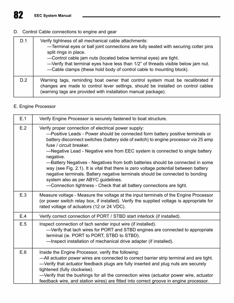
82 EEC System Manual
D. Control Cable connections to engine and gear
E. Engine Processor
D.1 Verify tightness of all mechanical cable attachments:—Terminal eyes or ball joint connections are fully seated with securing cotter pins split rings in place.—Control cable jam nuts (located below terminal eyes) are tight.—Verify that terminal eyes have less than 1/2” of threads visible below jam nut.—Cable clamps (these hold body of control cable to mounting block).
D.2 Warning tags, reminding boat owner that control system must be recalibrated ifchanges are made to control lever settings, should be installed on control cables(warning tags are provided with installation manual package).
E.1 Verify Engine Processor is securely fastened to boat structure.
E.2 Verify proper connection of electrical power supply:—Positive Leads - Power should be connected form battery positive terminals or battery disconnect switches (battery side of switch) to engine processor via 25 amp fuse / circuit breaker.—Negative Lead - Negative wire from EEC system is connected to single battery negative.—Battery Negatives - Negatives from both batteries should be connected in someway (see Fig. 2.1). It is vital that there is zero voltage potential between battery negative terminals. Battery negative terminals should be connected to bondingsystem also as per ABYC guidelines.—Connection tightness - Check that all battery connections are tight.
E.3 Measure voltage - Measure the voltage at the input terminals of the Engine Processor(or power switch relay box, if installed). Verify the supplied voltage is appropriate forrated voltage of actuators (12 or 24 VDC).
E.4 Verify correct connection of PORT / STBD start interlock (if installed).
E.5 Inspect connection of tach sender input wire (if installed).—Verify that tach wires for PORT and STBD engines are connected to appropriateterminal (ie. PORT to PORT, STBD to STBD).—Inspect installation of mechanical drive adapter (if installed).
E.6 Inside the Engine Processor, verify the following:—All actuator power wires are connected to correct barrier strip terminal and are tight.—Verify that actuator feedback plugs are fully inserted and plug nuts are securely tightened (fully clockwise).—Verify that the bushings for all the connection wires (actuator power wire, actuatorfeedback wire, and station wires) are fitted into correct groove in engine processor.

83Section 6.0 — System Test & Checkout
� Sea Trial Preparation Checks
A. Engine Processor
B. Mechanical backup operational test
E.7 Bonding wire should be connected between engine processor and engine room bond-ing system. Verify that battery negative is also connected to engine room bonding sys-tem.
Prior to sea trials, the system should be properly calibrated as per Section 5.0 and the mechanicalbackup control cables connected and adjusted as per Section 3.3
A.1 Verify that DIP switches are correctly set:—Correct number of control stations (Bank 2, Switches 1-3), see Section 5.1, page65 for details.—Correct synchronizer gain setting (Bank 2, Switches 5-8), see Section 6.0 fordetails.—EP is in Run Mode (Bank 2, Switch 4 and Switch 8 = OFF).After settings are checked and found to be correct, close DIP Switch Access coverand tighten (4) wing nuts.
A.2 Coil manual calibration control box into EP cavity. Close Engine Processor cover.
B.1 With engine OFF, test operate engine control system in manual mode. Ensure that,while in mechanical control, engine control handle can be moved from Neutral toAhead gear / full throttle to Astern gear / full throttle to Neutral.
B.2 Test transfer of control from electronic to manual using the following procedure:a) Turn ON EEC system and operate electronically.b) Take control at the station equipped for mechanical backup, and advance controlhandle to the Ahead gear / full throttle position.c) Turn OFF the EEC system. Verify that mechanical operation is regained.d) Repeat steps (a) through (c), for the Reverse gear / full throttle position.e) If the boat is equipped with a second electronic control station (remote station), turnON the EEC system and take control at the remote station and advance the enginecontrol to the Ahead gear / full throttle position.f) Turn OFF the EEC system. At the station equipped with mechanical backup, movethe control handles to the ahead gear / full throttle position. Verify that mechanicaloperation is regained at the mechanical backup control station.g) Repeat steps (e) through (f), for the Reverse gear / full throttle position.
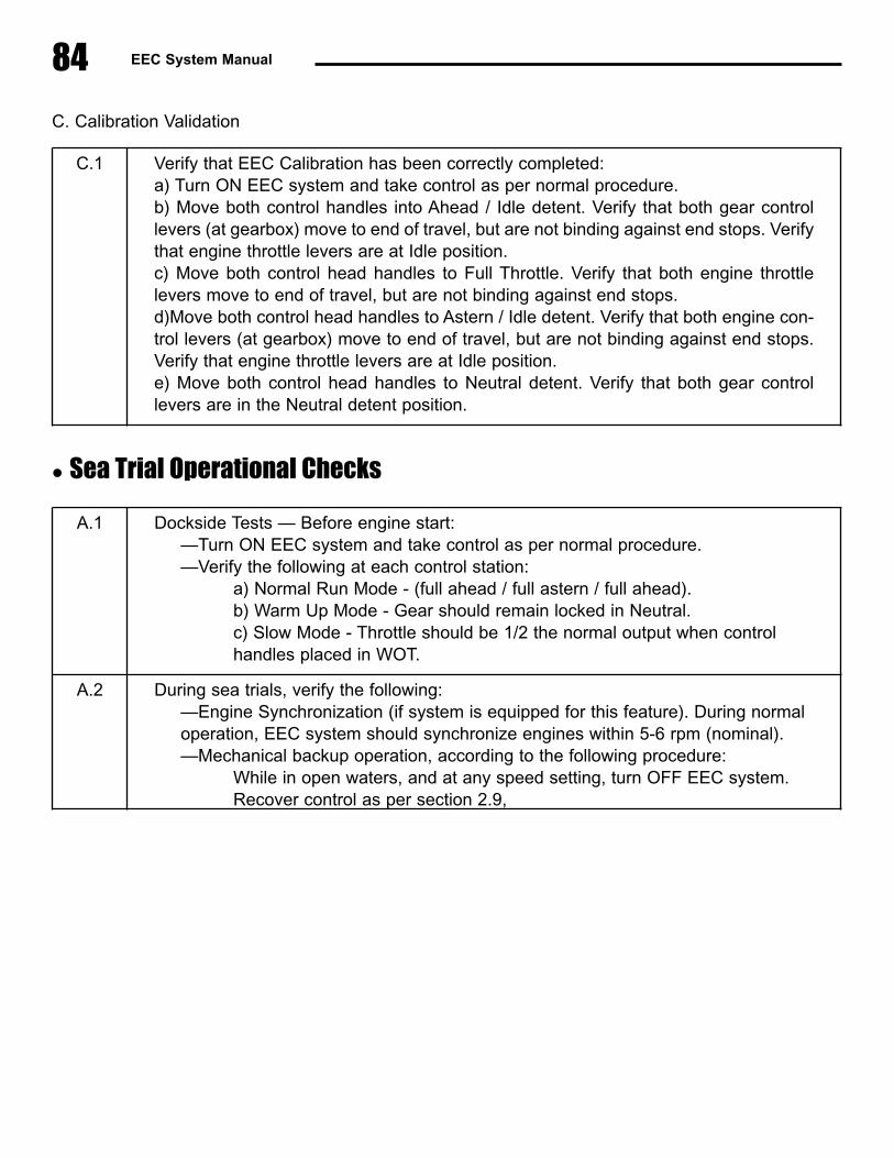
84 EEC System Manual
C. Calibration Validation
� Sea Trial Operational Checks
C.1 Verify that EEC Calibration has been correctly completed:a) Turn ON EEC system and take control as per normal procedure.b) Move both control handles into Ahead / Idle detent. Verify that both gear controllevers (at gearbox) move to end of travel, but are not binding against end stops. Verifythat engine throttle levers are at Idle position.c) Move both control head handles to Full Throttle. Verify that both engine throttlelevers move to end of travel, but are not binding against end stops.d)Move both control head handles to Astern / Idle detent. Verify that both engine con-trol levers (at gearbox) move to end of travel, but are not binding against end stops.Verify that engine throttle levers are at Idle position.e) Move both control head handles to Neutral detent. Verify that both gear controllevers are in the Neutral detent position.
A.1 Dockside Tests — Before engine start:—Turn ON EEC system and take control as per normal procedure.—Verify the following at each control station:
a) Normal Run Mode - (full ahead / full astern / full ahead).b) Warm Up Mode - Gear should remain locked in Neutral.c) Slow Mode - Throttle should be 1/2 the normal output when control handles placed in WOT.
A.2 During sea trials, verify the following:—Engine Synchronization (if system is equipped for this feature). During normal operation, EEC system should synchronize engines within 5-6 rpm (nominal).—Mechanical backup operation, according to the following procedure:
While in open waters, and at any speed setting, turn OFF EEC system. Recover control as per section 2.9,

85Section 7.0 — Troubleshooting
7.0 TroubleshootingIf difficulty is encountered during system operation, the following steps should be followed to determinethe cause and / or fix the problem:
1. If the vessel is underway, immediately regain mechanical backup control. All troubleshooting stepsshould be postponed until positive control over the vessel's engine and gear is regained.
2. If the difficulty occurs during system startup, follow the “EEC System Startup Sequence” flowchartdepicted on the next page. Almost always, system startup problems are caused by Control Heads notbeing positioned in the Neutral position prior to startup, or by adjustment problems caused by mechan-ical backup misalignment / misadjustment.
3. Perform the steps listed under “Troubleshooting Mode (Recover Alarm Codes) described in Section7.1. Obtain the following information:
— Number of alarm code that was most recently stored in memory— Alarm code LED sequence for each alarm in memory.
4. With the alarm code information gathered in Step #3 above, and with the Engine Processor serialnumber (located on the front cover of the Engine Processor), contact the product service personnel atGlendinning Marine Products, as follows:
Office phone: 800-500-2380Office fax: 843-399-5005Hours: 8:00 a.m. - 5:30 p.m. Monday - Friday (On many days, there are people at the factory either earlier or later than these hours)
Beeper: 843-477-6630When you hear the “three beeps”, please key in the phone number where you would like to be con-tacted at. We will try to call you back as soon as possible. Please understand that this is a specialbeeper which is dedicated to responding to urgent calls regarding the EEC product ONLY and is notto be used for calls relating to our other products.

EEC System Manual86
� EEC System Startup Sequence
Prior to EEC system startup, verify that MainControl Station is in Neutral position.
If the Main Control Station is not also themechanical backup station, verify that the
mechanical backup controls are also in theNeutral position.
Are Actuator solenoids engaged?
(Actuator solenoid engagement is indicated bycoupler plate center pin being fully retracted)
PORT Actuator solenoid will attempt to retractcoupler pins first; STBD Actuator solenoids will
be energized only if PORT Actuator couplerpin engagement is successful.
System will go into ALARM mode (indicatedby all 4 lights blinking in unison). Mechanical
backup mis-alignment is excessive.
1) Turn OFF EEC system.2) Adjust mechanical backup control head
position.3) Restart EEC system.
TAKE light will flash slowly.
Actuator solenoids will attempt to engage.
Does Actuator movement allow coupler platecenter pins to fully retract?
TAKE lightwill flash slowly accompanied
by a slow beep
Control Head — TAKE & WARM light ON.
System is ready for operation.
Actuators will move small amounts to aligncoupler plates.
Turn EEC system ON.
Is the Main Station Control Head in neutral position?
Move Main Station Control Headhandles to neutral position.
YES
YES
YES
NO
NO
NO
During the startup process, the EEC performs various diagnostic tests. In addition, the EEC systemmust changeover from mechanical backup operation (the failsafe mode that the system is in whenpowered OFF) to electronic operation.
Normally, mechanical backup canbe aligned with the electroniccontrol by adjusting the mechani-cal backup control head prior tosystem startup. If difficulty isencountered during startup, verifyalignment of coupler plates onactuators in engine compartment.
Prior to startup, gear and throttlecoupler plates on both gear /throttle actuators must be aligned(3 coupler plates / function).
GearActuatorCouplerPlates
ThrottleActuatorCouplerPlates
CouplerPlatePins

7.1 Troubleshoot Mode (Recover Alarm History)
As described above under Section 2.9, whenever the EEC system goes into the “Alarm Mode”, a codeis stored in the system memory which indicates the diagnostic alarm that was encountered. This errorcode may be retrieved from the system at any time, even if the system has been turned off or even ifthe system has experienced multiple, or cascading, failures.
The general procedure that is used to recover the Alarm error codes is as follows: 1) Identify the number of the last alarm code stored in memory2) Read each alarm code that is stored3) Clear the alarm code memory.
The following procedure is used to retrieve the Alarm Mode error codes:
IDENTIFY NUMBER OF STORED ALARM CODES
1. Turn “OFF” the EEC system. Open EP access panel to expose the LEDs and DIPswitches.
2. Verify or record the positions (ON/OFF) of each of the EP DIP switches with the “DIPswitch position table" that is kept in the front pocket of this manual. If they are notalready recorded, write them in the chart below:
NOTE: Bank #2, Switches 1 - 6 arethe only switch positions that need tobe recorded. Do not change the posi-tion of any other switches.
87Section 7.0 — Troubleshooting
This section is contained here for general information only. Troubleshoot Mode should only beaccomplished when directed by Glendinning Marine Products or by a technician who has beentrained by Glendinning Marine Products. Please contact Glendinning Marine Products for addition-al information.
DIP SWITCH
Bank 1
Bank 2
#1 #2 #3 #4
Engine Processor
“LO” EpromSerial Number
“HI” EpromSerial Number
These two lights are constantly litwhen EEC system is in operation.
Top
Bottom
LED Display8 7 6 5 4 3 2 1
SwitchBank 1
SwitchBank 2
Switch inON position
Switch inOFF position
#8#5 #6 #7

88 EEC System Manual
3. Position the DIP Switches as indicated below:
4. Turn ON the EEC system (use same switch at main helm station that is used to turn on the EECsystem during normal operation).
5. The alarm count will be displayed on the EP LED.
SWITCH BANK #1
Switch #4 — ON all others OFF
SWITCH BANK #2
ALL Switches — OFF
8 7 6 5 4 3 2 1
Alarm Count = 1
8 7 6 5 4 3 2 1
Alarm Count = 5
8 7 6 5 4 3 2 1
Alarm Count = 9
8 7 6 5 4 3 2 1
Alarm Count = 13
8 7 6 5 4 3 2 1
Alarm Count = 2
8 7 6 5 4 3 2 1
Alarm Count = 6
8 7 6 5 4 3 2 1
Alarm Count = 10
8 7 6 5 4 3 2 1
Alarm Count = 14
8 7 6 5 4 3 2 1
Alarm Count = 3
8 7 6 5 4 3 2 1
Alarm Count = 7
8 7 6 5 4 3 2 1
Alarm Count = 11
8 7 6 5 4 3 2 1
Alarm Count = 15
8 7 6 5 4 3 2 1
Alarm Count = 4
8 7 6 5 4 3 2 1
Alarm Count = 8
8 7 6 5 4 3 2 1
Alarm Count = 12
8 7 6 5 4 3 2 1
Alarm Count = 16
If no lights are visible, there are no alarm codes stored in memory. Proceed to Step 9 .
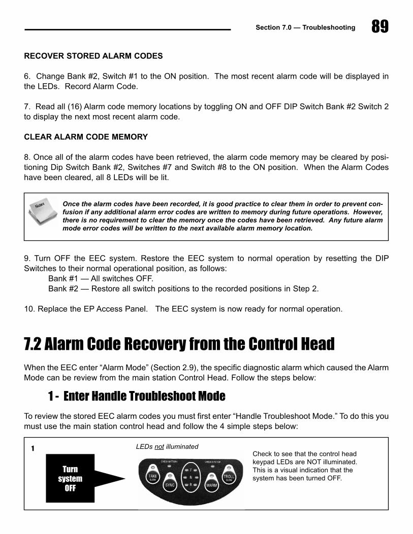
89Section 7.0 — Troubleshooting
RECOVER STORED ALARM CODES
6. Change Bank #2, Switch #1 to the ON position. The most recent alarm code will be displayed inthe LEDs. Record Alarm Code.
7. Read all (16) Alarm code memory locations by toggling ON and OFF DIP Switch Bank #2 Switch 2to display the next most recent alarm code.
CLEAR ALARM CODE MEMORY
8. Once all of the alarm codes have been retrieved, the alarm code memory may be cleared by posi-tioning Dip Switch Bank #2, Switches #7 and Switch #8 to the ON position. When the Alarm Codeshave been cleared, all 8 LEDs will be lit.
9. Turn OFF the EEC system. Restore the EEC system to normal operation by resetting the DIPSwitches to their normal operational position, as follows:
Bank #1 — All switches OFF. Bank #2 — Restore all switch positions to the recorded positions in Step 2.
10. Replace the EP Access Panel. The EEC system is now ready for normal operation.
7.2 Alarm Code Recovery from the Control HeadWhen the EEC enter “Alarm Mode” (Section 2.9), the specific diagnostic alarm which caused the AlarmMode can be review from the main station Control Head. Follow the steps below:
1 - Enter Handle Troubleshoot Mode
To review the stored EEC alarm codes you must first enter “Handle Troubleshoot Mode.” To do this youmust use the main station control head and follow the 4 simple steps below:
Once the alarm codes have been recorded, it is good practice to clear them in order to prevent con-fusion if any additional alarm error codes are written to memory during future operations. However,there is no requirement to clear the memory once the codes have been retrieved. Any future alarmmode error codes will be written to the next available alarm memory location.
Turn system
OFF
LEDs not illuminatedCheck to see that the control headkeypad LEDs are NOT illuminated.This is a visual indication that thesystem has been turned OFF.
1
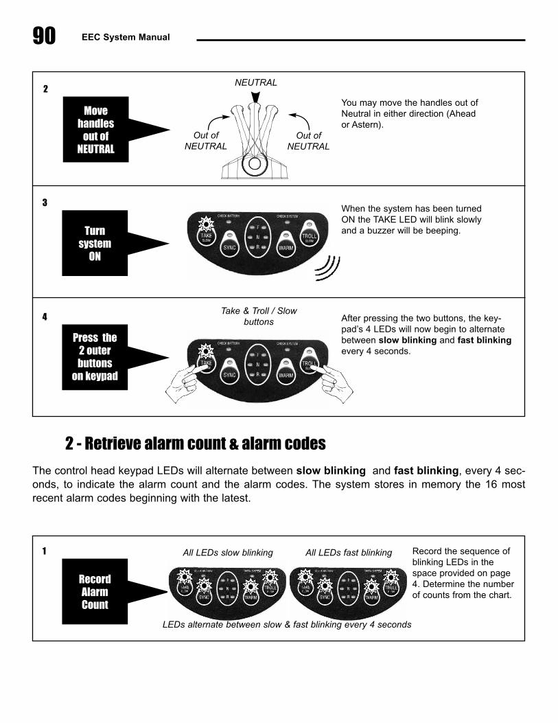
90 EEC System Manual
2 - Retrieve alarm count & alarm codes
The control head keypad LEDs will alternate between slow blinking and fast blinking, every 4 sec-onds, to indicate the alarm count and the alarm codes. The system stores in memory the 16 mostrecent alarm codes beginning with the latest.
Take & Troll / Slow buttons
NEUTRAL
You may move the handles out ofNeutral in either direction (Aheador Astern).
When the system has been turnedON the TAKE LED will blink slowlyand a buzzer will be beeping.
After pressing the two buttons, the key-pad’s 4 LEDs will now begin to alternatebetween slow blinking and fast blinkingevery 4 seconds.
Turn system
ON
3
Press the2 outerbuttons
on keypad
4
Movehandles
out ofNEUTRAL
2
RecordAlarmCount
All LEDs slow blinking Record the sequence ofblinking LEDs in thespace provided on page4. Determine the numberof counts from the chart.
1 All LEDs fast blinking
LEDs alternate between slow & fast blinking every 4 seconds
Out ofNEUTRAL
Out ofNEUTRAL
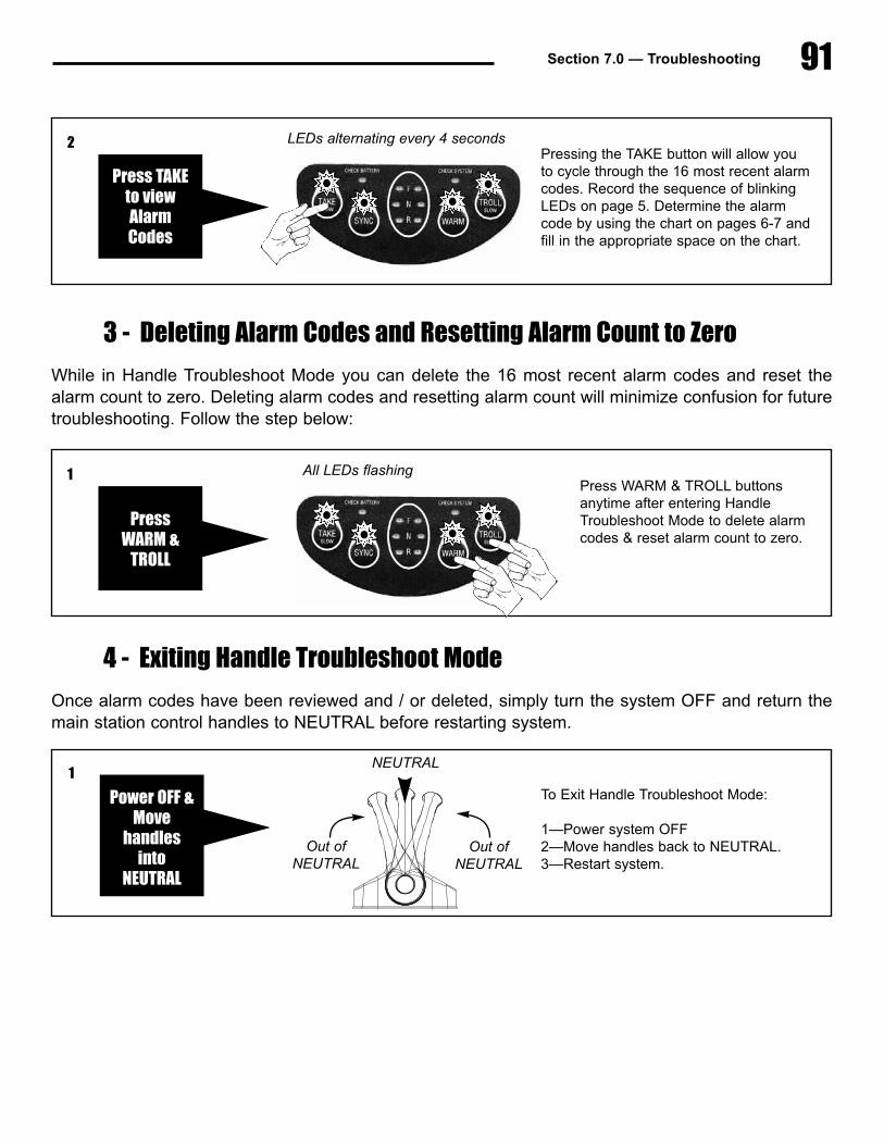
91Section 7.0 — Troubleshooting
3 - Deleting Alarm Codes and Resetting Alarm Count to Zero
While in Handle Troubleshoot Mode you can delete the 16 most recent alarm codes and reset thealarm count to zero. Deleting alarm codes and resetting alarm count will minimize confusion for futuretroubleshooting. Follow the step below:
4 - Exiting Handle Troubleshoot Mode
Once alarm codes have been reviewed and / or deleted, simply turn the system OFF and return themain station control handles to NEUTRAL before restarting system.
Press TAKEto viewAlarmCodes
LEDs alternating every 4 secondsPressing the TAKE button will allow youto cycle through the 16 most recent alarmcodes. Record the sequence of blinkingLEDs on page 5. Determine the alarmcode by using the chart on pages 6-7 andfill in the appropriate space on the chart.
2
PressWARM &
TROLL
All LEDs flashing
NEUTRAL
Out ofNEUTRAL
Out ofNEUTRAL
To Exit Handle Troubleshoot Mode:
1—Power system OFF2—Move handles back to NEUTRAL.3—Restart system.
Press WARM & TROLL buttonsanytime after entering HandleTroubleshoot Mode to delete alarmcodes & reset alarm count to zero.
1
Power OFF &Move
handlesinto
NEUTRAL
1
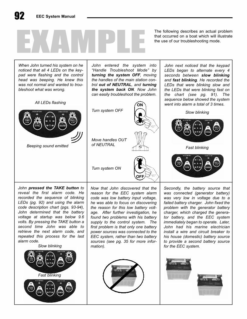
92 EEC System Manual
All LEDs flashing
When John turned his system on henoticed that all 4 LEDs on the key-pad were flashing and the controlhead was beeping. He knew thiswas not normal and wanted to trou-bleshoot what was wrong.
John next noticed that the keypadLEDs began to alternate every 4seconds between slow blinkingand fast blinking. He recorded theLEDs that were blinking slow andthe LEDs that were blinking fast onthe chart (see pg. 91). Thesequence below showed the systemwent into alarm a total of 3 times.
John pressed the TAKE button toreveal the first alarm code. Herecorded the sequence of blinkingLEDs (pg. 92) and using the alarmcode description chart (pgs. 93-94),John determined that the batteryvoltage at startup was below 9.6volts. By pressing the TAKE button asecond time John was able toretrieve the next alarm code, andrepeated this process for the lastalarm code.
Now that John discovered that thereason for the EEC system alarmcode was low battery input voltage,he was able to focus on discoveringthe reason for this low battery volt-age. After further investigation, hefound two problems with his batterysupply to the control system. Thefirst problem is that only one batterypower sources was connected to theEEC system, rather than two batterysources (see pg. 35 for more infor-mation).
Secondly, the battery source thatwas connected (generator battery)was very low in voltage due to afailed battery charger. John fixed theproblem with the generator batterycharger, which charged the genera-tor battery, and the EEC systemimmediately began to operate. Later,John had his marine electricianinstall a wire and circuit breaker tohis house (domestic) battery sourceto provide a second battery sourcefor the EEC system.
John entered the system into“Handle Troubleshoot Mode” byturning the system OFF, movingthe handles of the main station con-trol out of NEUTRAL, and turningthe system back ON. Now Johncan easily troubleshoot the problem.
Beeping sound emitted
Turn system OFF
Turn system ON
Move handles OUTof NEUTRAL
ON
OFF
ON
OFF
Slow blinking
Fast blinking
Slow blinking
Fast blinking
EXAMPLEThe following describes an actual problemthat occurred on a boat which will illustratethe use of our troubleshooting mode.

93Section 7.0 — Troubleshooting
Alarm Count Chart
TAKE
1
2
3
4
5
6
7
8
9
10
11
12
13
14
15
16
17
18
19
20
21
22
23
24
25
26
27
28
29
30
31
32
CO
UN
T LEDs SLOW BLINKING LEDs FAST BLINKING
SYNC WARM TROLL TAKE SYNC WARM TROLL TAKE
33
34
35
36
37
38
39
40
41
42
43
44
45
46
47
48
49
50
51
52
53
54
55
56
57
58
59
60
61
62
63
64
CO
UN
T LEDs SLOW BLINKING LEDs FAST BLINKING
SYNC WARM TROLL TAKE SYNC WARM TROLL
TAKE
LEDs SLOW BLINKING LEDs FAST BLINKINGSYNC WARM TROLL TAKE SYNC WARM TROLL = alarm count

94 EEC System Manual
Record alarm codes
Pressing the TAKE button will advance from the alarm count to alarm codes 1 - 16. Record each alarmcode by placing an “X” in the appropriate space on the chart (below). After recording each alarm codepress TAKE to cycle through each code.
Once all alarm codes have been recorded, look up the alarm code in the table (on the following pages)and record the alarm code description in the space provided next to each alarm code above.
1
2
3
4
5
6
7
8
9
10
11
12
13
14
15
16
TAKE#
LEDs SLOW BLINKING LEDs FAST BLINKING
SYNC WARM TROLL TAKE SYNC WARM TROLL
ALARM CODEDESCRIPTION

95Section 7.0 — Troubleshooting
Alarm Codes Description chart
Check alarm code values that you recorded on the opposite page with the list of alarm code descrip-tions below. Enter the description in the appropriate column on the chart.
TAKE
LEDs SLOW BLINKING LEDs FAST BLINKING
SYNC
No handle connected to CP at startup.
Master handle moved out of neutral during engagement of the solenoids.
Reference supply too low (<4.655V for 3 seconds).
Reference supply too high (>5.355V for 3 seconds).
Nine volt power supply too low (<8.33V for 3 seconds).
Nine volt power supply too high (<12.139V for 3 seconds).
Relay power supply too low (<9.5V engage/startup or <6.0V run).
Relay power supply too high (>12.6V for 3 seconds).
Battery below 9.6V (12V) or 20.7V (24V) for 3 seconds.
Battery above 15.6V (12V) or 30.0V (24V) for 3 seconds.
Battery below 9.6V at startup.
Battery above 15.6V but below 20.7V at startup.
Battery above 30.0V at startup.
Port throttle actuator high current, above 10 amps, for 4.8 seconds.
Stbd throttle actuator high current, above 10 amps, for 4.8 seconds.
Port gear actuator high current, above 10 amps, for 4.8 seconds.
Stbd gear actuator high current, above 10 amps, for 4.8 seconds.
Port troll actuator high current, above 10 amps, for 4.8 seconds.
Stbd troll actuator high current, above 10 amps, for 4.8 seconds.
Port throttle actuator high current, above 8 amps, for 10 seconds.
Stbd throttle actuator high current, above 8 amps, for 10 seconds.
Port gear actuator high current, above 8 amps, for 10 seconds.
Stbd gear actuator high current, above 8 amps, for 10 seconds.
Port troll actuator high current, above 8 amps, for 10 seconds.
Stbd troll actuator high current, above 8 amps, for 10 seconds.
Port th actuator problem. Error between command and feedback too large.
Port gr actuator problem. Error between command and feedback too large.
Port tv actuator problem. Error between command and feedback too large.
Stbd th actuator problem. Error between command and feedback too large.
Stbd gr actuator problem. Error between command and feedback too large.
Stbd tv actuator problem. Error between command and feedback too large.
WARM TROLL TAKE SYNC WARM TROLL
ALARM CODEDESCRIPTION
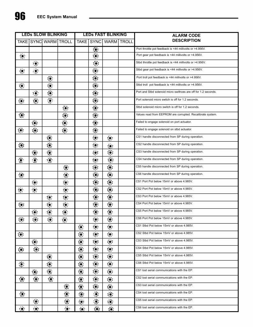
96 EEC System Manual
TAKE
LEDs SLOW BLINKING LEDs FAST BLINKING
SYNC
Port throttle pot feedback is <44 millivolts or >4.956V.
Port gear pot feedback is <44 millivolts or >4.956V.
Stbd throttle pot feedback is <44 millivolts or >4.956V.
Stbd gear pot feedback is <44 millivolts or >4.956V.
Port troll pot feedback is <44 millivolts or >4.956V.
Stbd troll pot feedback is <44 millivolts or >4.956V.
Port and Stbd solenoid micro swithces are off for 1.2 seconds.
Port solenoid micro swtich is off for 1.2 seconds.
Stbd solenoid micro switch is off for 1.2 seconds.
Values read from EEPROM are corrupted. Recalibrate system.
Failed to engage solenoid on port actuator.
Failed to engage solenoid on stbd actuator.
CS1 handle disconnected from SP during operation.
CS2 handle disconnected from SP during operation.
CS3 handle disconnected from SP during operation.
CS4 handle disconnected from SP during operation.
CS5 handle disconnected from SP during operation.
CS6 handle disconnected from SP during operation.
CS1 Port Pot below 15mV or above 4.985V.
CS2 Port Pot below 15mV or above 4.985V.
CS3 Port Pot below 15mV or above 4.985V.
CS4 Port Pot below 15mV or above 4.985V.
CS5 Port Pot below 15mV or above 4.985V.
CS6 Port Pot below 15mV or above 4.985V.
CS1 Stbd Pot below 15mV or above 4.985V.
CS2 Stbd Pot below 15mV or above 4.985V.
CS3 Stbd Pot below 15mV or above 4.985V.
CS4 Stbd Pot below 15mV or above 4.985V.
CS5 Stbd Pot below 15mV or above 4.985V.
CS6 Stbd Pot below 15mV or above 4.985V.
CS1 lost serial communications with the EP.
CS2 lost serial communications with the EP.
CS3 lost serial communications with the EP.
CS4 lost serial communications with the EP.
CS5 lost serial communications with the EP.
CS6 lost serial communications with the EP.
WARM TROLL TAKE SYNC WARM TROLL
ALARM CODEDESCRIPTION

Section 7.0 — Troubleshooting 97
7.3 Troubleshooting Chart1) The following problems may be encountered during system startup:
PROBLEM / SYMPTON POSSIBLE FAILURE RECOMMENDATION
After turning ON powerswitch or circuit breakers,EEC system will not turn
ON.
No input power to Engine Processor A) Verify that at least one source of 12 or 24VDC is available at EP power supply input barrierstrip.B) Verify that EP circuit breakers are ON.
After turning ON powerswitch “TAKE” light slowlyblinks but system will not
start up.
Main station Control head handlesare not in Neutral detent position.
Leave power switch ON. Move handles toNeutral detent position. EEC system will auto-matically begin intinialization and startup proce-dures.
5-6 seconds after turningon Power switch, all four
lights blink simultaneously,along with Control Head
buzzer sounding & CheckSystem light is blinking.
EEC system was unable to engageelectronic control (All lights blinking
simultaneously indicates that systemhas entered “Alarm Mode” — Light
code 3, 7, “No EEC”).
Mechanical backup control cables are incorrectlyadjusted.
Low battery voltage — System hasenough voltage to start up EngineProcessor, but not enough voltage
for solenoid “pull up” current.
A) Check voltage at EP input terminals duringstartup process. If battery voltage is low, chargebatteries.B) Verify alignment of coupler plates on Actuatorprior to system startup. Try pushing in couplerpins during system startup.
“Neutral detent” potentiometer inControl Head defective.
A) Cycle control handles several times (Fullahead—Full Reverse—Full Ahead) and thenrepeat startup process.B) For boats equipped with 2 or more stations,change SP connections at EP to place a differ-ent station in S#1 position. Repeat startupprocess.C) Replace control head.
Power switch relay box defective A) Verify 12 or 24 VDC across input terminals ofPower switch relay box. If no voltage isobserved, power supply from vessel batteries isproblem.B) If voltage is present at input terminals, turnon power switch at helm station. Verify that 12or 24 VDC is present at power switch relay boxoutput terminal strip. If no voltage is observed,then power switch relay box is probably defec-tive.
EEC internal failure Open Dip switch access cover. While assistantturns ON power switch, observe EP LEDs andrecord pattern of lights which turn on. Call GMPfor technical help.
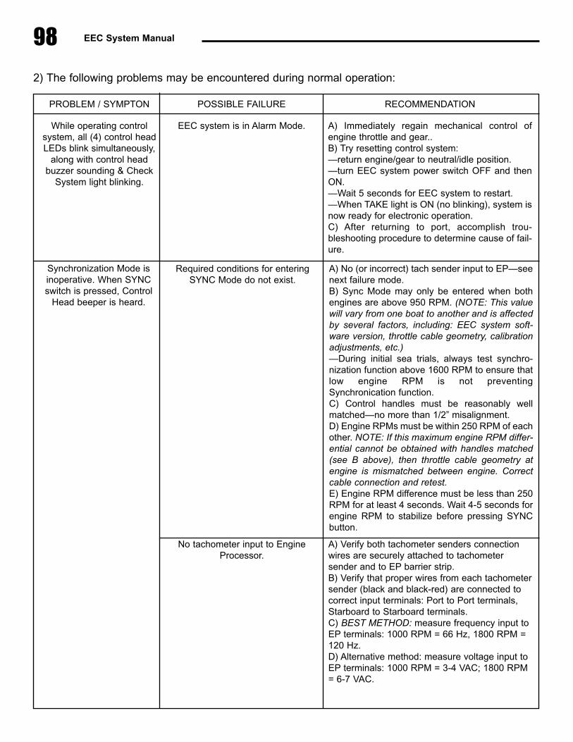
98 EEC System Manual
2) The following problems may be encountered during normal operation:
PROBLEM / SYMPTON POSSIBLE FAILURE RECOMMENDATION
While operating controlsystem, all (4) control headLEDs blink simultaneously,
along with control headbuzzer sounding & Check
System light blinking.
EEC system is in Alarm Mode. A) Immediately regain mechanical control ofengine throttle and gear..B) Try resetting control system:—return engine/gear to neutral/idle position.—turn EEC system power switch OFF and thenON.—Wait 5 seconds for EEC system to restart.—When TAKE light is ON (no blinking), system isnow ready for electronic operation.C) After returning to port, accomplish trou-bleshooting procedure to determine cause of fail-ure.
Synchronization Mode isinoperative. When SYNCswitch is pressed, Control
Head beeper is heard.
No tachometer input to EngineProcessor.
A) Verify both tachometer senders connectionwires are securely attached to tachometersender and to EP barrier strip.B) Verify that proper wires from each tachometersender (black and black-red) are connected tocorrect input terminals: Port to Port terminals,Starboard to Starboard terminals.C) BEST METHOD: measure frequency input toEP terminals: 1000 RPM = 66 Hz, 1800 RPM =120 Hz.D) Alternative method: measure voltage input toEP terminals: 1000 RPM = 3-4 VAC; 1800 RPM= 6-7 VAC.
Required conditions for enteringSYNC Mode do not exist.
A) No (or incorrect) tach sender input to EP—seenext failure mode.B) Sync Mode may only be entered when bothengines are above 950 RPM. (NOTE: This valuewill vary from one boat to another and is affectedby several factors, including: EEC system soft-ware version, throttle cable geometry, calibrationadjustments, etc.)—During initial sea trials, always test synchro-nization function above 1600 RPM to ensure thatlow engine RPM is not preventingSynchronication function.C) Control handles must be reasonably wellmatched—no more than 1/2” misalignment.D) Engine RPMs must be within 250 RPM of eachother. NOTE: If this maximum engine RPM differ-ential cannot be obtained with handles matched(see B above), then throttle cable geometry atengine is mismatched between engine. Correctcable connection and retest.E) Engine RPM difference must be less than 250RPM for at least 4 seconds. Wait 4-5 seconds forengine RPM to stabilize before pressing SYNCbutton.

Section 7.0 — Troubleshooting 99
PROBLEM / SYMPTON POSSIBLE FAILURE RECOMMENDATION
In Troll Mode, with full han-dle deflection, no propeller
shaft movement.
Troll actuator endpoint positions notcorrectly calibrated.
Recalibrate troll actuator endpoint positions.
In Troll Mode, propellershaft does not move until40% or more control han-
dle movement.
Too much deadband on transmissiontroll lever
Recalibrate troll actuator endpoint positions.
Call GMP
While in electronic mode,control handles are movedbut engine / gear does not
respond.
Electronic engine control has failed. A) Immediately regain mechanical control ofengine throttle and gear.B) Check control head indicator lights to see ifthey are blinking—if so, EEC system is in AlarmMode.

100 EEC System Manual

Section 8.0 — Appendix / Reference
8.0 Appendix / ReferenceA. Wiring Diagram . . . . . . . . . . . . . . . . . . . . . . . . . . . . . . . . . . . . . . . . . . . . . . . . . . . . . . . . . . . . . . 102B. Engine Processor Dimensions . . . . . . . . . . . . . . . . . . . . . . . . . . . . . . . . . . . . . . . . . . . . . . . . . . . 103C. Actuator Dimensions . . . . . . . . . . . . . . . . . . . . . . . . . . . . . . . . . . . . . . . . . . . . . . . . . . . . . . . . . . 104D. Station Processor Dimensions. . . . . . . . . . . . . . . . . . . . . . . . . . . . . . . . . . . . . . . . . . . . . . . . . . . 105E. Control Head - Mechanical Backup Dimensions . . . . . . . . . . . . . . . . . . . . . . . . . . . . . . . . . . . . . 106F. Control Head - Remote (Electric only) Dimensions . . . . . . . . . . . . . . . . . . . . . . . . . . . . . . . . . . . 107G. New Style Top Mount Control Head . . . . . . . . . . . . . . . . . . . . . . . . . . . . . . . . . . . . . . . . . . . . . . 108H. Sidemount Control Head Installation . . . . . . . . . . . . . . . . . . . . . . . . . . . . . . . . . . . . . . . . . . . . . . 109I. Control Head Template (New Style). . . . . . . . . . . . . . . . . . . . . . . . . . . . . . . . . . . . . . . . . . . . . . . . 111J. Sidemount Wiring Diagram . . . . . . . . . . . . . . . . . . . . . . . . . . . . . . . . . . . . . . . . . . . . . . . . . . . . . . 112K. Sidemount Keypad Assembly Template . . . . . . . . . . . . . . . . . . . . . . . . . . . . . . . . . . . . . . . . . . . . 113
8.1 Custom Configuration OptionsA. Control Station Custom Options. . . . . . . . . . . . . . . . . . . . . . . . . . . . . . . . . . . . . . . . . . . . . . . . . . 116B. Gear Custom Options. . . . . . . . . . . . . . . . . . . . . . . . . . . . . . . . . . . . . . . . . . . . . . . . . . . . . . . . . . 117C. Throttle Custom Options . . . . . . . . . . . . . . . . . . . . . . . . . . . . . . . . . . . . . . . . . . . . . . . . . . . . . . . 121D. Troll Custom Options . . . . . . . . . . . . . . . . . . . . . . . . . . . . . . . . . . . . . . . . . . . . . . . . . . . . . . . . . . 122E. Other Custom Options . . . . . . . . . . . . . . . . . . . . . . . . . . . . . . . . . . . . . . . . . . . . . . . . . . . . . . . . . 126
101
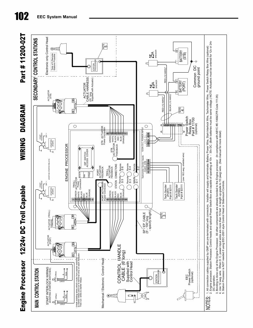
102 EEC System Manual
ST
B���
AC
TU
AT
OR
Pow
er�C
onne
ctio
n
ST
BA
CT
UA
TO
RF
EE
DB
AC
K
PO
RT
�AC
TU
AT
OR
Pow
er�C
onne
ctio
nF
EE
DB
AC
K
PO
RT
AC
TU
AT
OR
STAT
ION�
��CO
NNEC
TIO
NS
MA
INS
�1S
�2
S�3
S�4
S�5
S�6
Rem
ote
Rem
ote
Rem
ote
Rem
ote
Rem
oteSer
ial�#
Dat
e
Vol
tage
GR
EE
N
OR
AN
GE
WH
ITE
BLA
CK
RE
DB
LUE
GR
EE
NW
HIT
EB
LAC
KR
ED
BLU
EO
RA
NG
E
12/2
4v�D
.C.�P
OW
ER
�INP
UT
--+
+Ta
chom
eter
�Sen
der�
Inpu
tsP
OR
TS
TB
�STA
TIO
N�P
RO
CE
SS
OR
�
��STA
TIO
N�P
RO
CE
SS
OR
�
BATT
ERY
(PO
RT)
BATT
ERY
���(S
TB)
+
EN
GIN
E��P
RO
CE
SS
OR
AC
TU
AT
OR
���(P
OR
T)
MAIN
CON
TROL
STAT
ION
SECO
NDAR
Y C
ONTR
OL S
TATI
ONS
Tota
l�of�5
�Rem
ote
Sta
tions
�Pos
sibl
e
BLA
CK
�(12
�AW
G)*
RE
D�(
12�A
WG
)*
Com
mon
DC
grou
nd�p
oint
CO
NT
RO
L��H
AN
DLE
CA
BLE
��(6'
�long
)
AC
TU
AT
OR
CA
BLE
�HA
RN
ES
S
SP
�/�E
PC
AB
LE(5'�-
�100'�l
ong�
��-
�spe
cify
�leng
th)
NOTE
S:
(use
�18/
2�aw
g��s
hiel
ded�
wire
)�
�Sup
plie
d�w
ith�C
ontr
ol�H
ead
���(20'�l
ong�
supp
lied�
with
�Act
uato
r)
BR
EA
KE
R
NO
TE 4
25A
�DIP
��SW
ITC
HA
CC
ES
S��C
OV
ER
Pow
er�S
witc
hR
elay
�Box
Par
t�#�1
1700
(opt
iona
l)
EE
CP
ower
�Sw
itch
���(o
ptio
nal)
+
Eng
ine
Pro
cess
or
12/2
4v D
C T
roll
Cap
able
WIR
ING
D
IAG
RA
M
Part
# 1
1200
-02T
BR
EA
KE
R
25AR
ED
�(12
�AW
G)*
1.�A
ll�co
nnec
tion�
cabl
es�s
uppl
ied�by
�GM
P�a
re�p
re-t
erm
inat
ed�w
ith�c
onne
ctor
s.��I
nsta
ller�
will
�sup
ply�
and�
term
inat
e:�B
atte
ry�P
ower
�Wire,�S
tart
-Int
erlo
ck�W
ire,�T
acho
met
er�W
ire,
Pow
er�S
witc
h�R
elay
�Box
�Wire
�(op
tiona
l)2.
�Eng
ine�
proc
esso
r,�S
tatio
n�P
roce
ssor,�C
ontr
ol�h
eads
�and
�opt
iona
l�Pow
er�S
witc
h�B
ox�a
re�c
apab
le�of�o
pera
ting�
at�10v
��-��30v
�DC
.�(B
oth�ba
tterie
s�m
ust�b
e�sa
me�
volta
ge.)
�NO
TE:�A
ctua
tors
�mus
t�be�
orde
redfo
r�12
v�or
�24v
��D
C�o
pera
tion.
3.�B
ondi
ng�is
�don
e�on
ly�a
t�the
�Eng
ine�
Pro
cess
or.��
All�
othe
r�co
mpo
nent
s�ar
e�al
readybo
nded
�to�th
e�E
ngin
e�pr
oces
sor
�(In
�com
plia
nce�
with:A
BY
C�#
E-1
46&
CF
R�C
ode�
111.05
)4.
�Use
�12�
awg.
�wire
.��W
hen�
D.�C
.�pow
er�in
put�w
ires�
are�
mor
e�th
an�1
5�fe
et��i
n�le
ngth
�up-
grad
e�to
�10�
(aw
g)�w
ire.��
(See
�man
ualf
or�m
ore�
deta
il)5.
�Sta
tion�
Pro
cess
or�is
�NO
T�n
eede
d�if�
usin
g�E
EC
-200
1�styl
e�C
ontr
ol�H
ead�
or�S
idem
ount
�Con
trol
s.
RU
N+
+ RU
N
START
START(EX
IST
ING
�STA
RT
ER
�SW
ITC
HE
S)
(Oth
er)
(Oth
er)
-�br
eak�
exis
ting�
wire
s�w
hich
�rou
te�fr
om�s
tart
er�s
witc
hes�
��to�
star
ter�
relays
�and
�run
�to�te
rmin
al�s
trip
�on�
each
�Act
auto
r.��T
hen�
run�
�wire
s�to
�sta
rter
�rel
ays.
STA
RT
�INT
ER
LOC
K�W
IRIN
GS
TAR
TE
R(P
OR
T)
�STA
RT
SO
LEN
OID
(EX
IST
ING
�STA
RT
ER
�RE
LAY
S)
Tach
�Sen
der
(PO
RT
)P
art�#
�931
11
BA
T.�+
BLA
CK
RE
DB
LUE
OR
AN
GE
FE
ED
BA
CK
���T
RO
LLA
CT
UA
TO
R
AC
TU
AT
OR
��(T
RO
LL)
����(
optio
nal)
���T
RO
LLA
CT
UA
TO
RP
ower
Con
nect
ion
AC
TU
AT
OR
�(S
TB
)
Tach
�Sen
der
(ST
BD
)P
art�#
�931
11
NO
TE 3
STA
RT
ER
��(P
OR
T)
�STA
RT
SO
LEN
OID
BA
T.�+
Mec
hani
cal�/
�Ele
ctro
nic�
�Con
trol
�Hea
d
Ele
ctro
nic�
only
�Con
trol
�Hea
d
WH
ITE
GR
EE
N
NO
TE 5
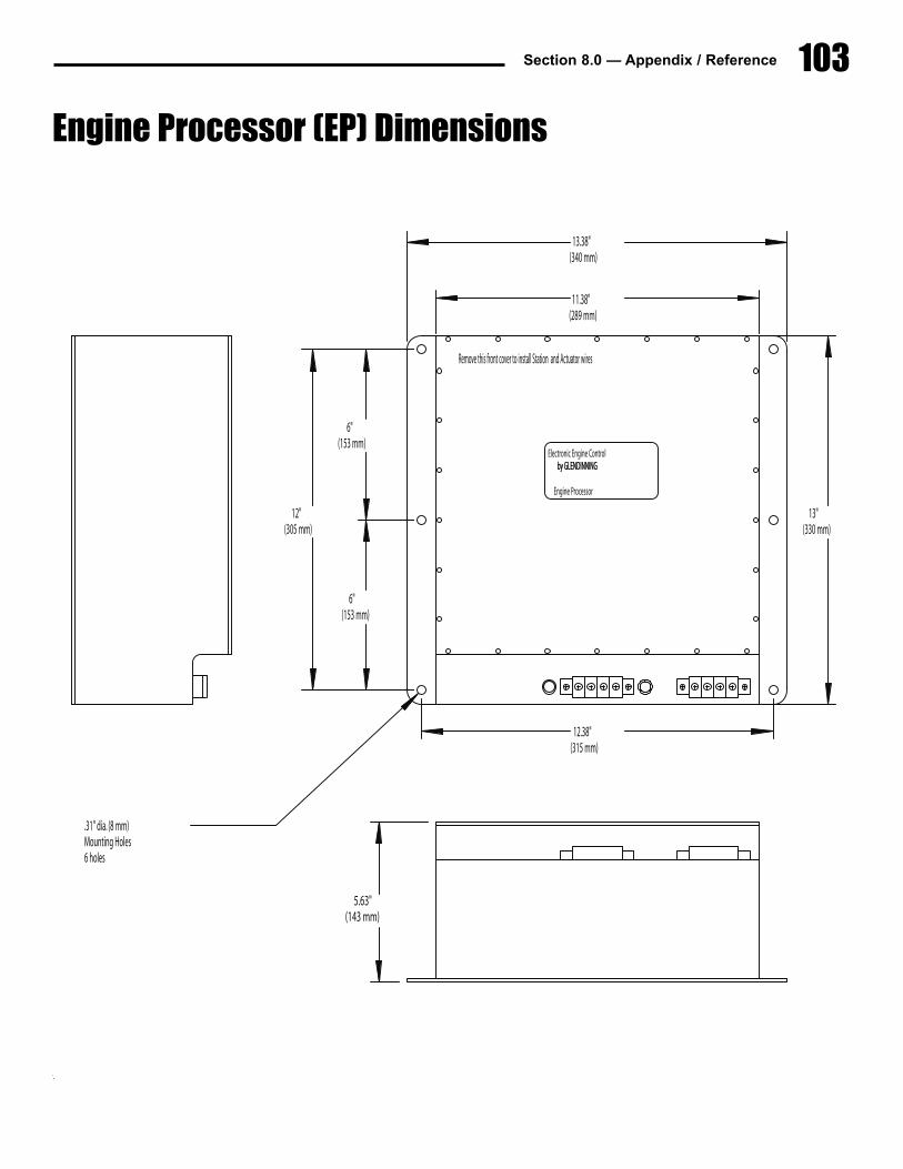
Section 8.0 — Appendix / Reference 103
Electronic Engine Control by GLENDINNING by GLENDINNING
Engine Processor
5.63"(143 mm)
E:
11.38"(289 mm)
13.38"(340 mm)
12.38"(315 mm)
Remove this front cover to install Station and Actuator wires
6"(153 mm)
6"(153 mm)
12"(305 mm)
R.P.M. InputsD.C. Inputs
13"(330 mm)
.31" dia. (8 mm)Mounting Holes6 holes
Engine Processor (EP) Dimensions
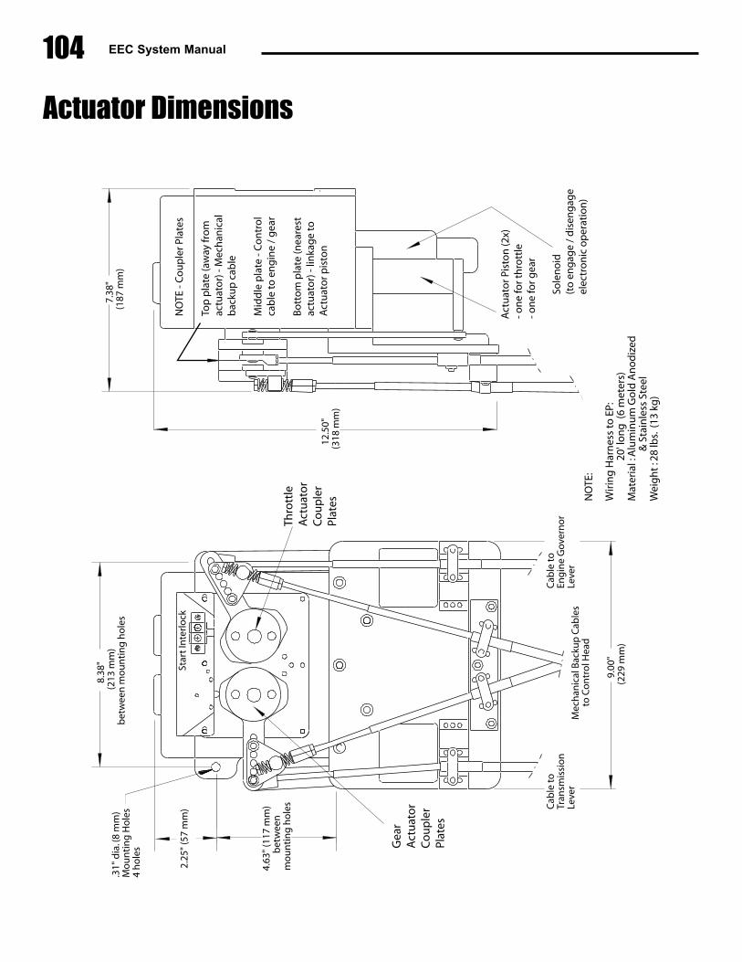
104 EEC System Manual
7.38
"(1
87 m
m)
8.38
"(2
13 m
m)
bet
wee
n m
ou
nti
ng
ho
les
2.25
" (5
7 m
m)
4.63
" (1
17 m
m)
bet
wee
nm
ou
nti
ng
ho
les
.31"
dia
. (8
mm
) M
ou
nti
ng
Ho
les
4 h
ole
s
Mec
han
ical
Bac
kup
Cab
les
to C
on
tro
l Hea
d
Cab
le to
Tran
smis
sio
n
Leve
r
Cab
le to
Eng
ine
Gov
ern
or
Leve
r
9.00
"(2
29 m
m)
12.5
0"(3
18 m
m)
NO
TE:
Wir
ing
Har
nes
s to
EP:
2
0' lo
ng
(6
met
ers)
Mat
eria
l : A
lum
inu
m G
old
An
od
ized
&
Sta
inle
ss S
teel
Wei
gh
t : 2
8 lb
s. (1
3 kg
)
Star
t In
terl
ock
NO
TE -
Co
up
ler P
late
s
Top
pla
te (a
way
fro
mac
tuat
or)
- M
ech
anic
alb
acku
p c
able
Mid
dle
pla
te -
Co
ntr
ol
cab
le to
en
gin
e /
gea
r
Bo
tto
m p
late
(nea
rest
actu
ato
r) -
linka
ge
toA
ctu
ato
r pis
ton
Act
uat
or P
isto
n (2
x)- o
ne
for t
hro
ttle
- on
e fo
r gea
r
Sole
no
id(t
o e
ng
age
/ d
isen
gag
eel
ectr
on
ic o
per
atio
n)
Gea
rA
ctu
ato
rC
ou
ple
rPl
ates
Thro
ttle
Act
uat
or
Co
up
ler
Plat
es
Actuator Dimensions
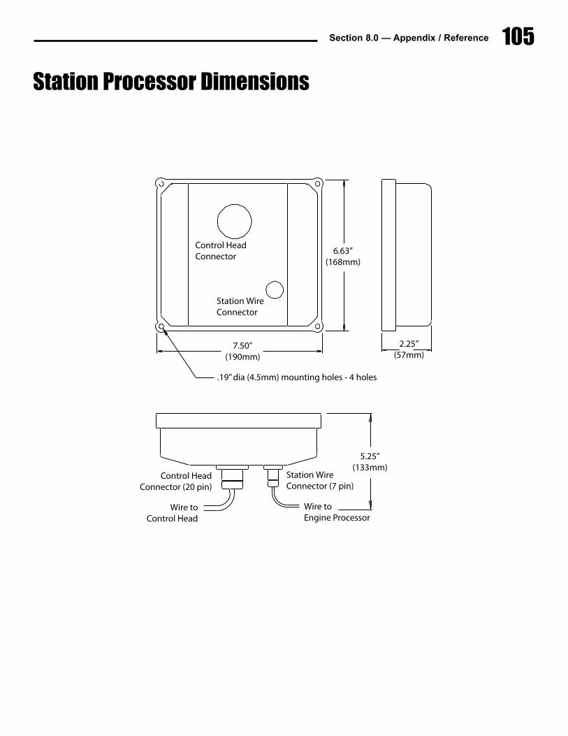
Section 8.0 — Appendix / Reference 105
Control HeadConnector
Station WireConnector
6.63”(168mm)
.19” dia (4.5mm) mounting holes - 4 holes
7.50”(190mm)
5.25”(133mm)
Wire toEngine Processor
Wire toControl Head
Control HeadConnector (20 pin)
Station WireConnector (7 pin)
2.25”(57mm)
Station Processor Dimensions
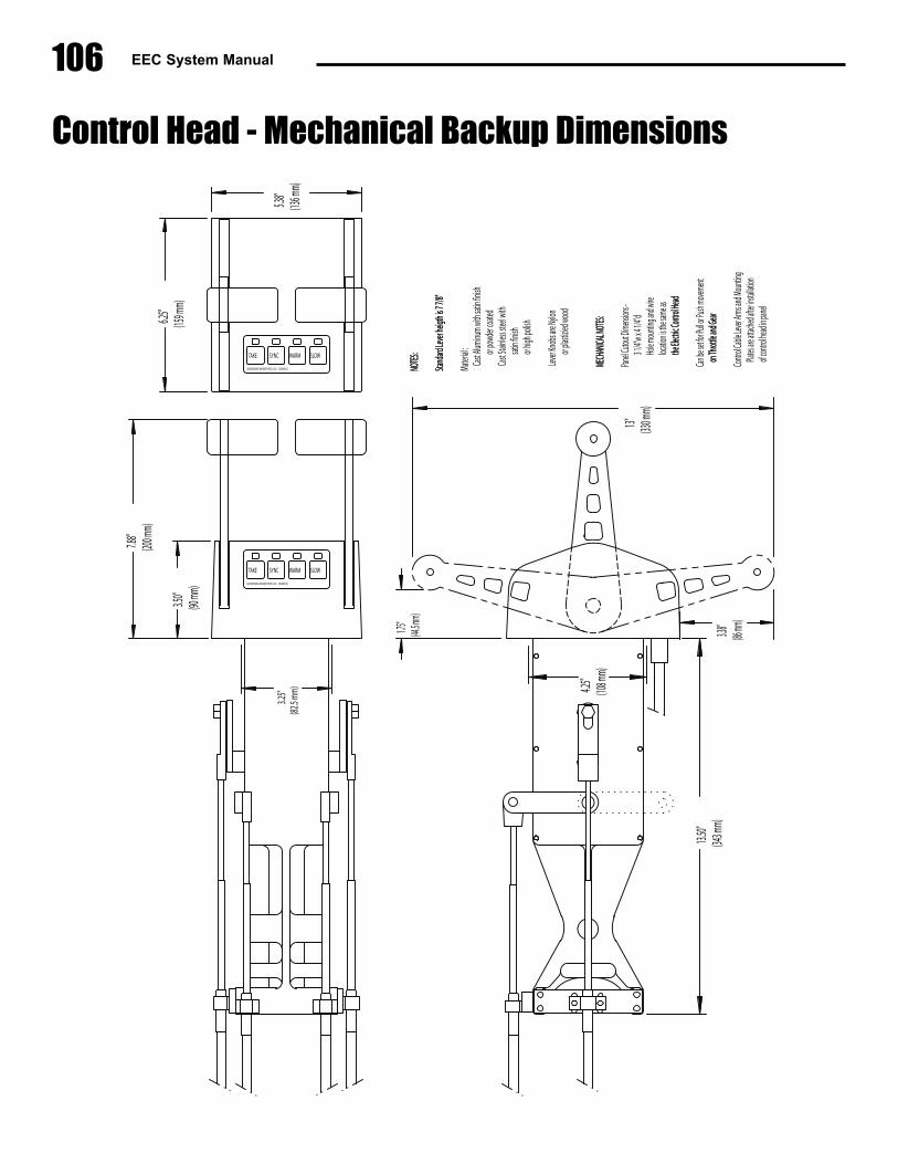
106 EEC System Manual
3.25
"(82
.5 mm
)
3.38"
(86 mm
)
NOTES
:NO
TES:
Stand
ard Le
ver he
igth is
7 7/8"
Stand
ard Le
ver he
igth is
7 7/8"
Mater
ial :
Cast A
luminu
m wit
h sati
n fini
sh or
powd
er coa
tedCa
st Stai
nless s
teel w
ith
satin
finish
or hig
h poli
sh
Lever
Knob
s are
Nylon
or
plast
izied w
ood
13.50
"(34
3 mm)
MECH
ANICA
L NOT
ES:ME
CHAN
ICAL N
OTES:
Panel C
utout
Dimens
ions -
3 1/4"
w x 4 1
/4"d
Hole m
ounti
ng an
d wire
locatio
n is th
e sam
e as
the Ele
ctric C
ontro
l Head
the Ele
ctric C
ontro
l Head
Can be
set fo
r Pull o
r Push
movem
ent
on Th
rottle
and Ge
aron
Throt
tle and
Gear
Contr
ol Cabl
e Leve
r Arm
s and
Moun
ting
Plates
are att
ached
after i
nstalla
tion
of con
trol he
ad in p
anel
4.25"
(108 m
m)
5.38"
(136 m
m)
6.25"
(159 m
m)
7.88"
(200 m
m)
1.75"
(44.5 m
m)
GLENDINNING MARINE PRODS., INC. CONWAY,SC
TAKE SYNC WARM SLOW
GLENDINNING MARINE PRODS., INC. CONWAY,SC
TAKE SYNC WARM SLOW
13" (330 m
m)
3.50"
(90 mm
)
Control Head - Mechanical Backup Dimensions
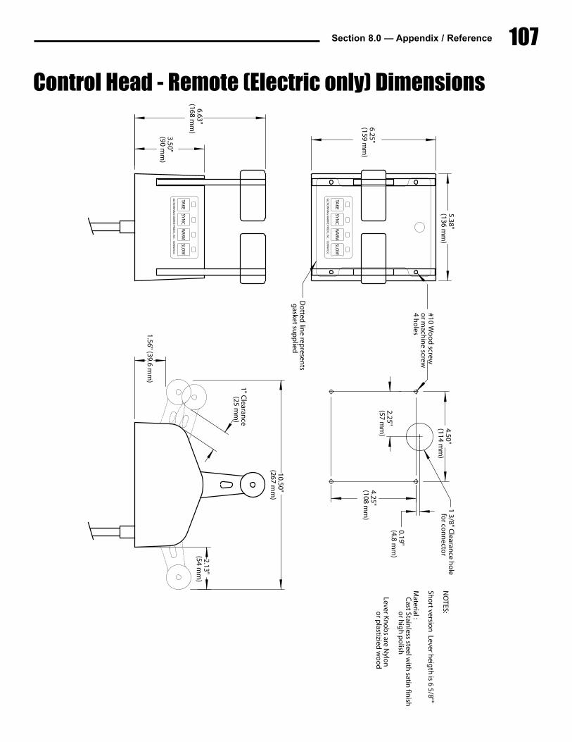
Section 8.0 — Appendix / Reference 107
5.38"(136 m
m)
6.25"(159 m
m)
GLEN
DIN
NIN
G M
ARIN
E PROD
S., INC
. CO
NW
AY,SC
TAK
ESY
NC
WARM
SLOW
GLEN
DIN
NIN
G M
ARIN
E PROD
S., INC
. CO
NW
AY,SC
TAK
ESY
NC
WARM
SLOW
NO
TES:
Sho
rt version
Lever heig
th is 6 5/8""
Material :C
ast Stainless steel w
ith satin
finish
or h
igh
po
lish
Lever Kn
ob
s are Nylo
n
or p
lastizied w
oo
d
Do
tted lin
e represen
ts g
asket sup
plied
#10 Wo
od
screwo
r mach
ine screw
4 ho
les
1 3/8" Clearan
ce ho
le fo
r con
necto
r
2.25"(57 m
m)
4.50"(114 m
m)
4.25"(108 m
m)
0.19"(4.8 m
m)
3.50"(90 m
m)
1" Clearan
ce(25 m
m)
6.63"(168 m
m)
10.50"(267 m
m)
1.56" (39.6 mm
)
2.13"(54 m
m)
Control Head - Remote (Electric only) Dimensions
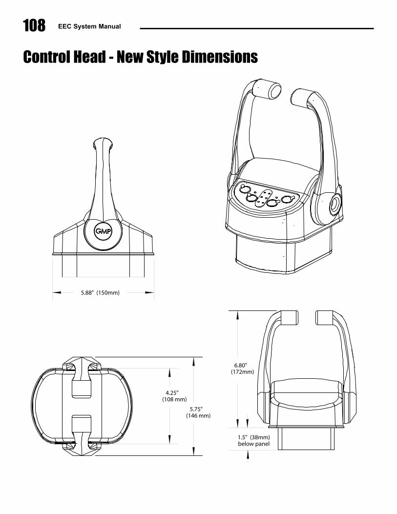
108 EEC System Manual
5.75" (146 mm)
4.25" (108 mm)
6.80"(172mm)
1.5" (38mm) below panel
5.88" (150mm)
Control Head - New Style Dimensions
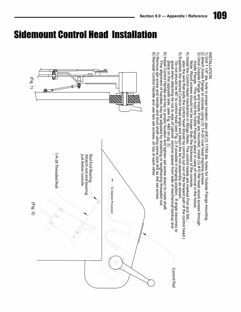
Section 8.0 — Appendix / Reference 109IN
STA
LLAT
ION
1)�Drill�1�1/4"�dia.�hole�in�proper�location;�also�drill�(3)�17/64�dia.�holes�for�O
utside�Flange�m
ounting2)�A
ttach�Inside�Flange�to�console�using�(3)�1/4-20�oval�head�m
achine�screws
3)�Once�O
utside�Flange�and�Inside�F
lange�are�mounted,�install�(3)�#10�flat�head�w
ood�screws�through
��Inside�Flange.��T
his�will�hold�the�Inside�F
lange�in�place�in�case�of�removal�in�the�future.
��Note:�W
ood�screws�should�not�be�longer�than�the�thickness�of�the�console.
4)�Install�the�Control�H
ead�mechanism
�in�flange�(Note:�T
he�control�heads�are�marked�P
ort�and�Stb.;
��also�the�wire�that�exits�the�control�head�should�be�com
ing�out�out�of�the�forward�part�of�the�control�head.)
5)�Establish�the�desired�C
ontrol�Head�angle�and�attach�the�tie�rod�assem
bly�as�shown.
��Tie�rod�should�be�90°�to�control�head�(see�F
ig.�2)�if�possible�in�hanging�position.��If�angle�becomes�to�
��great�when�attaching�tie�rod�to�side�of�cabinet,�rem
ove�spacer�from�side�of�m
echanical�backup�and��place�on�the�opposite�side.�(see�F
ig.�4&5�on�pg.�2)
6)�Install�Control�H
andle�and�key�in�proper�location�and�tighten�set�screw�dow
n�to�mark�shaft.
��Fine�alignm
ent�of�handles�may�be�adjusted�by�shotening�or�lengthening�threaded�rod.
7)�Rem
ove�set�screw�and�handle�and�divot�shaft�using�sam
e�size�drill�as�the�set�screw.
8)�Reinstall�C
ontrol�Handle�and�use�tw
o�set�screws,�on�top�of�each�other.�
To Statio
n Pro
cessor
Co
ntro
l Pad
(Fig.�2)
1/4-28 Thread
edR
od
Ro
d En
d B
earing
Attatch
rod
end
bearin
gju
st belo
w co
nso
le
(Fig.�1)
Sidemount Control Head Installation

110 EEC System Manual
6 1/
4"(1
25m
m)
13 3
/8"
(340
mm
)
4 1/
4"(1
08m
m)
17"
(432
mm
)
(152
mm
)
1 1/
2" M
ax(3
8mm
)
Spac
er
Spac
er
(Fig
.�3)
(Fig
.�4)
(Fig
.�5)
Bac
kup
cab
le to
Act
uat
or f
or
tran
smis
sio
n
Bac
kup
cab
le to
Act
uat
or f
or
eng
ine
gov
ern
or
Bac
kup
cab
le to
Act
uat
or f
or
eng
ine
gov
ern
or
Bac
kup
cab
le to
Act
uat
or f
or
tran
smis
sio
n
5 1/2' wire toControl Pad
Sidemount Control Head Installation
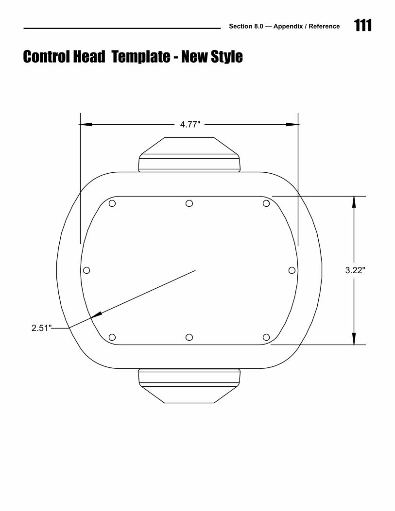
111Section 8.0 — Appendix / Reference
CoMCu
4.77"
3.22"
2.51"
Control Head Template - New Style
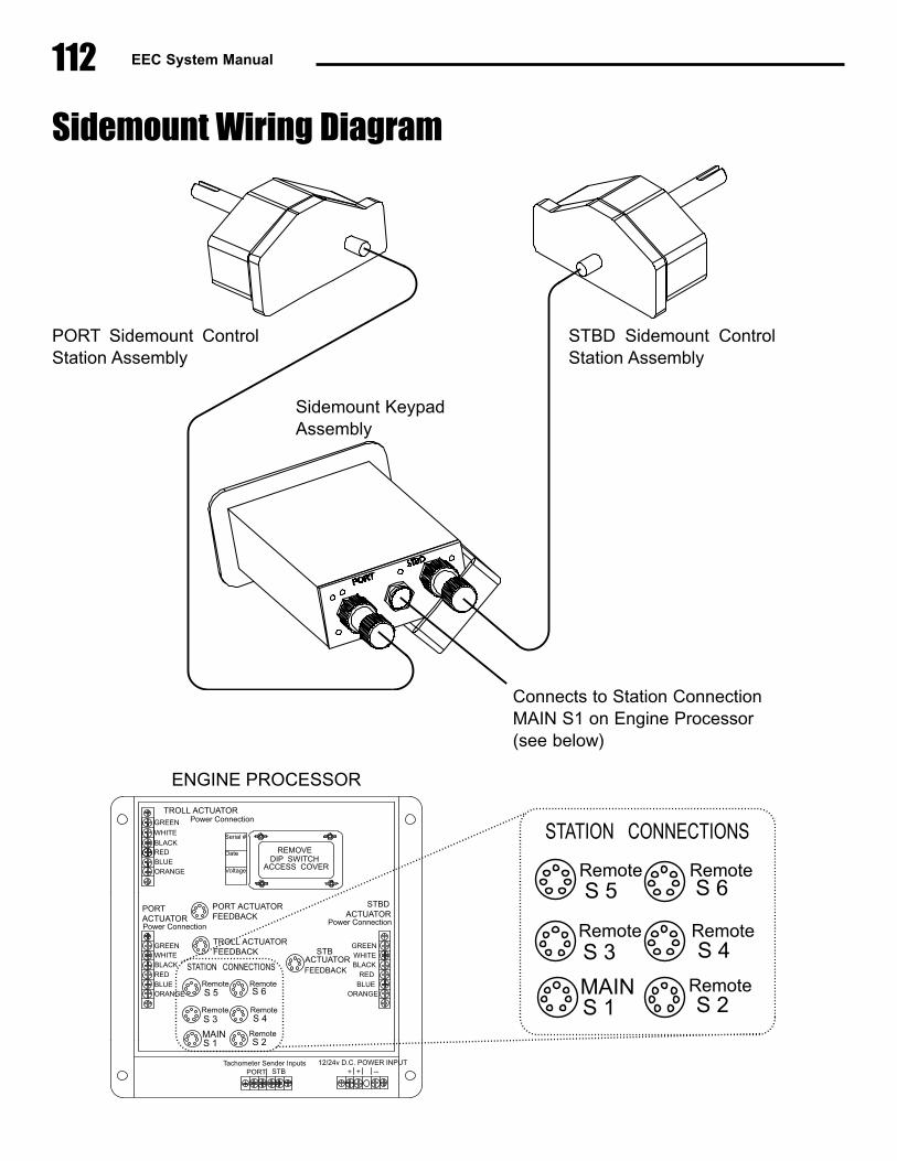
112 EEC System Manual
Sidemount Wiring Diagram
PORT Sidemount ControlStation Assembly
STBD Sidemount ControlStation Assembly
Sidemount KeypadAssembly
Connects to Station Connection MAIN S1 on Engine Processor (see below)
STBD�ACTUATOR
Power�Connection
�����STBACTUATORFEEDBACK
PORTACTUATORPower�Connection
PORT�ACTUATORFEEDBACK
STATION���CONNECTIONS
MAINS�1 S�2
S�3 S�4
S�5 S�6
Remote
Remote
Remote
Remote
Remote
Serial�#
Date
Voltage
GREEN
ORANGE
WHITEBLACKREDBLUE
GREENWHITEBLACK
REDBLUE
ORANGE
12/24v�D.C.�POWER�INPUT--++
Tachometer�Sender�InputsPORT STB
���DIP��SWITCHACCESS��COVER
BLACKREDBLUEORANGE
TROLL�ACTUATORFEEDBACK
TROLL�ACTUATOR����Power�Connection
WHITE
GREEN
���REMOVE
STATION���CONNECTIONS
MAINS�1 S�2
S�3 S�4
S�5 S�6
Remote
Remote
Remote
Remote
Remote
ENGINE�PROCESSOR
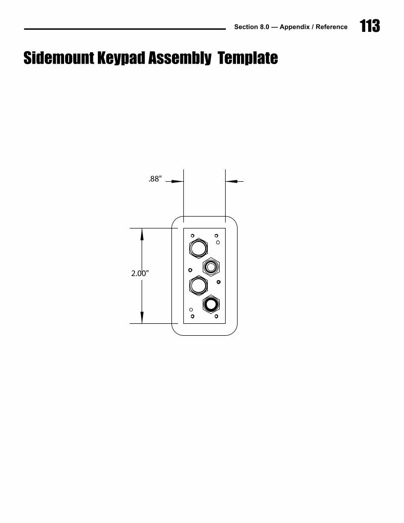
113Section 8.0 — Appendix / Reference
2.00"
.88"
Sidemount Keypad Assembly Template

114 EEC System Manual
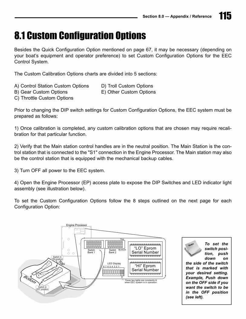
115Section 8.0 — Appendix / Reference
8.1 Custom Configuration OptionsBesides the Quick Configuration Option mentioned on page 67, it may be necessary (depending onyour boat’s equipment and operator preference) to set Custom Configuration Options for the EECControl System.
The Custom Calibration Options charts are divided into 5 sections:
A) Control Station Custom Options D) Troll Custom OptionsB) Gear Custom Options E) Other Custom OptionsC) Throttle Custom Options
Prior to changing the DIP switch settings for Custom Configuration Options, the EEC system must beprepared as follows:
1) Once calibration is completed, any custom calibration options that are chosen may require recali-bration for that particular function.
2) Verify that the Main station control handles are in the neutral position. The Main Station is the con-trol station that is connected to the "S1" connection in the Engine Processor. The Main station may alsobe the control station that is equipped with the mechanical backup cables.
3) Turn OFF all power to the EEC system.
4) Open the Engine Processor (EP) access plate to expose the DIP Switches and LED indicator lightassembly (see illustration below).
To set the Custom Configuration Options follow the 8 steps outlined on the next page for eachConfiguration Option:
Engine Processor
“LO” EpromSerial Number
“HI” EpromSerial Number
These two lights are constantly litwhen EEC system is in operation.
Top
Bottom
LED Display8 7 6 5 4 3 2 1
SwitchBank 1
SwitchBank 2
Switch inON position
Switch inOFF position
To set theswitch posi-tion, pushdown on
the side of the switchthat is marked withyour desired setting.Example, Push downon the OFF side if youwant the switch to bein the OFF position(see left).
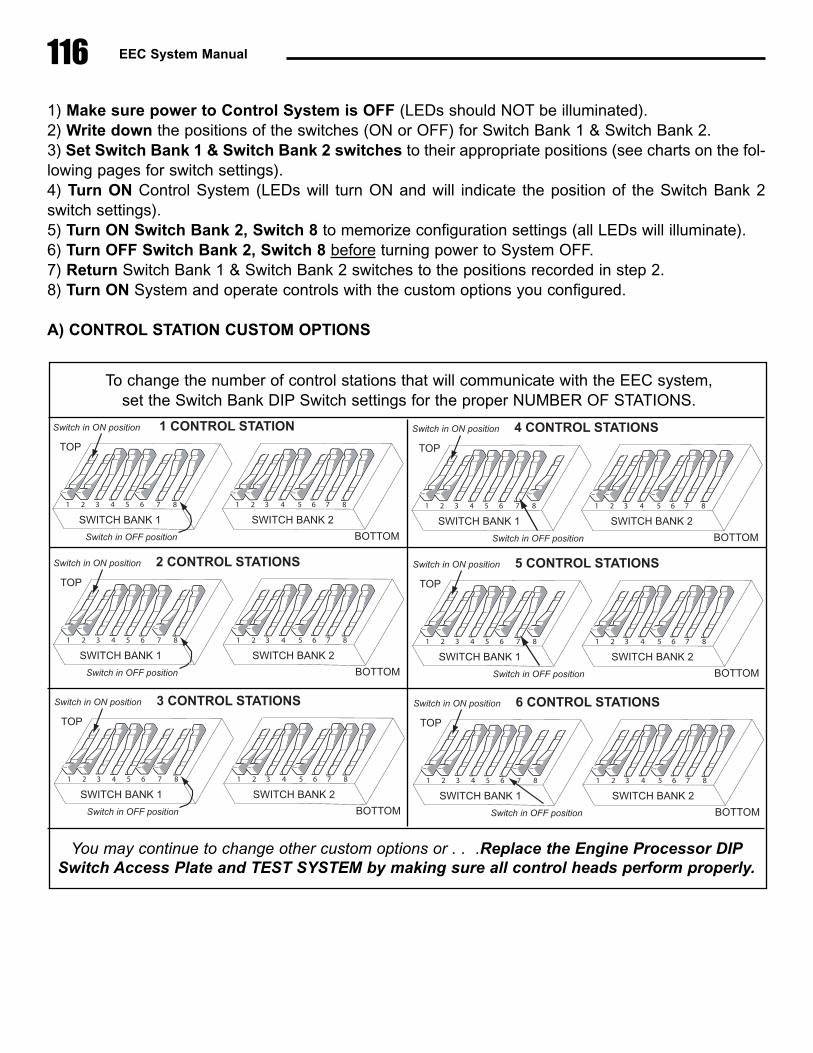
116 EEC System Manual
1) Make sure power to Control System is OFF (LEDs should NOT be illuminated).2) Write down the positions of the switches (ON or OFF) for Switch Bank 1 & Switch Bank 2.3) Set Switch Bank 1 & Switch Bank 2 switches to their appropriate positions (see charts on the fol-lowing pages for switch settings).4) Turn ON Control System (LEDs will turn ON and will indicate the position of the Switch Bank 2switch settings).5) Turn ON Switch Bank 2, Switch 8 to memorize configuration settings (all LEDs will illuminate).6) Turn OFF Switch Bank 2, Switch 8 before turning power to System OFF.7) Return Switch Bank 1 & Switch Bank 2 switches to the positions recorded in step 2.8) Turn ON System and operate controls with the custom options you configured.
A) CONTROL STATION CUSTOM OPTIONS
To change the number of control stations that will communicate with the EEC system, set the Switch Bank DIP Switch settings for the proper NUMBER OF STATIONS.
6 7 831 5422 3 5 6 7 81 4
SWITCH�BANK�1 SWITCH�BANK�2
1�CONTROL�STATION
TOP
BOTTO
Switch�in�ON�position
S i h i OFF i i
You may continue to change other custom options or . . .Replace the Engine Processor DIPSwitch Access Plate and TEST SYSTEM by making sure all control heads perform properly.
6 7 831 5422 3 5 6 7 81 4
SWITCH�BANK�1 SWITCH�BANK�2
1�CONTROL�STATION
TOP
BOTTOM
Switch�in�ON�position
Switch�in�OFF�position
6 7 831 5422 3 5 6 7 81 4
SWITCH�BANK�1 SWITCH�BANK�2
4�CONTROL�STATIONS
TOP
BOTTOM
Switch�in�ON�position
Switch�in�OFF�position
6 7 831 5422 3 5 6 7 81 4
SWITCH�BANK�1 SWITCH�BANK�2
2�CONTROL�STATIONS
TOP
BOTTOM
Switch�in�ON�position
Switch�in�OFF�position
6 7 831 5422 3 5 6 7 81 4
SWITCH�BANK�1 SWITCH�BANK�2
5�CONTROL�STATIONS
TOP
BOTTOM
Switch�in�ON�position
Switch�in�OFF�position
6 7 831 5422 3 5 6 7 81 4
SWITCH�BANK�1 SWITCH�BANK�2
3�CONTROL�STATIONS
TOP
BOTTOM
Switch�in�ON�position
Switch�in�OFF�position
6 7 831 5422 3 5 6 7 81 4
SWITCH�BANK�1 SWITCH�BANK�2
6�CONTROL�STATIONS
TOP
BOTTOM
Switch�in�ON�position
Switch�in�OFF�position
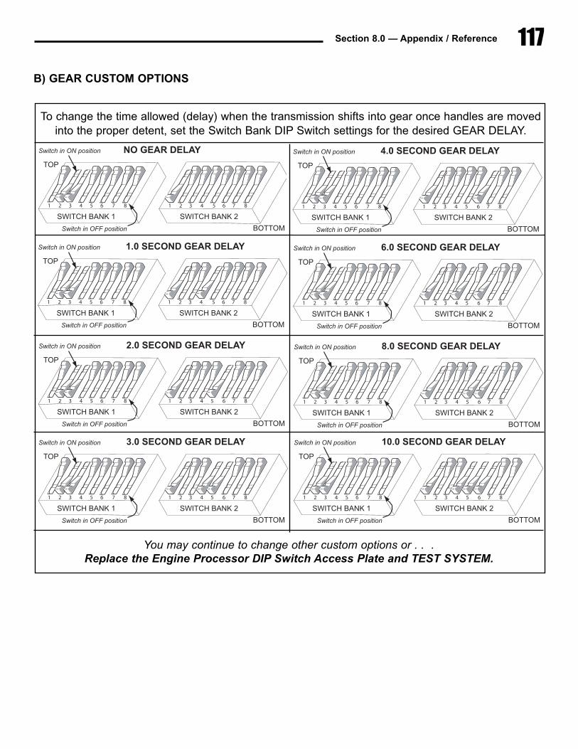
117Section 8.0 — Appendix / Reference
B) GEAR CUSTOM OPTIONS
To change the time allowed (delay) when the transmission shifts into gear once handles are movedinto the proper detent, set the Switch Bank DIP Switch settings for the desired GEAR DELAY.
6 7 831 5422 3 5 6 7 81 4
SWITCH�BANK�1 SWITCH�BANK�2
1�CONTROL�STATION
TOP
BOTTO
Switch�in�ON�position
S i h i OFF i i
You may continue to change other custom options or . . .Replace the Engine Processor DIP Switch Access Plate and TEST SYSTEM.
6 7 831 5422 3 5 6 7 81 4
SWITCH�BANK�1 SWITCH�BANK�2
NO�GEAR�DELAY
TOP
BOTTOM
Switch�in�ON�position
Switch�in�OFF�position
6 7 83 41 522 3 5 6 7 81 4
SWITCH�BANK�1 SWITCH�BANK�2
4.0�SECOND�GEAR�DELAY
TOP
BOTTOM
Switch�in�ON�position
Switch�in�OFF�position
6 7 83 41 522 3 5 6 7 81 4
SWITCH�BANK�1 SWITCH�BANK�2
1.0�SECOND�GEAR�DELAY
TOP
BOTTOM
Switch�in�ON�position
Switch�in�OFF�position
6 7 83 41 522 3 5 6 7 81 4
SWITCH�BANK�1 SWITCH�BANK�2
6.0�SECOND�GEAR�DELAY
TOP
BOTTOM
Switch�in�ON�position
Switch�in�OFF�position
6 7 83 41 522 3 5 6 7 81 4
SWITCH�BANK�1 SWITCH�BANK�2
2.0�SECOND�GEAR�DELAY
TOP
BOTTOM
Switch�in�ON�position
Switch�in�OFF�position
6 7 83 41 522 3 5 6 7 81 4
SWITCH�BANK�1 SWITCH�BANK�2
8.0�SECOND�GEAR�DELAY
TOP
BOTTOM
Switch�in�ON�position
Switch�in�OFF�position
6 7 83 41 522 3 5 6 7 81 4
SWITCH�BANK�1 SWITCH�BANK�2
3.0�SECOND�GEAR�DELAY
TOP
BOTTOM
Switch�in�ON�position
Switch�in�OFF�position
6 7 83 41 522 3 5 6 7 81 4
SWITCH�BANK�1 SWITCH�BANK�2
10.0�SECOND�GEAR�DELAY
TOP
BOTTOM
Switch�in�ON�position
Switch�in�OFF�position
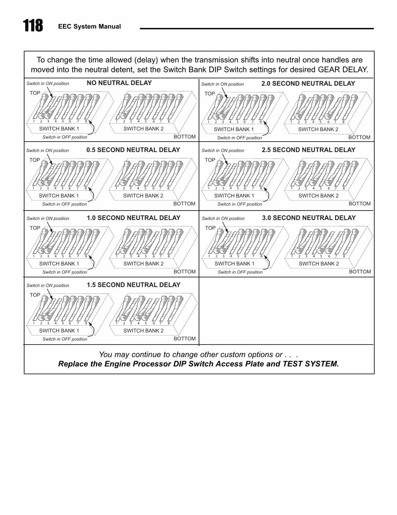
118 EEC System Manual
To change the time allowed (delay) when the transmission shifts into neutral once handles aremoved into the neutral detent, set the Switch Bank DIP Switch settings for desired GEAR DELAY.
6 7 831 5422 3 5 6 7 81 4
SWITCH�BANK�1 SWITCH�BANK�2
1�CONTROL�STATION
TOP
BOTTO
Switch�in�ON�position
S i h i OFF i i
You may continue to change other custom options or . . .Replace the Engine Processor DIP Switch Access Plate and TEST SYSTEM.
6 7 83 41 522 3 5 6 7 81 4
SWITCH�BANK�1 SWITCH�BANK�2
NO�NEUTRAL�DELAY
TOP
BOTTOM
Switch�in�ON�position
Switch�in�OFF�position
6 7 83 41 522 3 5 6 7 81 4
SWITCH�BANK�1 SWITCH�BANK�2
2.0�SECOND�NEUTRAL�DELAY
TOP
BOTTOM
Switch�in�ON�position
Switch�in�OFF�position
6 7 83 41 522 3 5 6 7 81 4
SWITCH�BANK�1 SWITCH�BANK�2
0.5�SECOND�NEUTRAL�DELAY
TOP
BOTTOM
Switch�in�ON�position
Switch�in�OFF�position
6 7 83 41 522 3 5 6 7 81 4
SWITCH�BANK�1 SWITCH�BANK�2
2.5�SECOND�NEUTRAL�DELAY
TOP
BOTTOM
Switch�in�ON�position
Switch�in�OFF�position
6 7 83 41 522 3 5 6 7 81 4
SWITCH�BANK�1 SWITCH�BANK�2
1.0�SECOND�NEUTRAL�DELAY
TOP
BOTTOM
Switch�in�ON�position
Switch�in�OFF�position
6 7 83 41 522 3 5 6 7 81 4
SWITCH�BANK�1 SWITCH�BANK�2
3.0�SECOND�NEUTRAL�DELAY
TOP
BOTTOM
Switch�in�ON�position
Switch�in�OFF�position
6 7 83 41 522 3 5 6 7 81 4
SWITCH�BANK�1 SWITCH�BANK�2
1.5�SECOND�NEUTRAL�DELAY
TOP
BOTTOM
Switch�in�ON�position
Switch�in�OFF�position
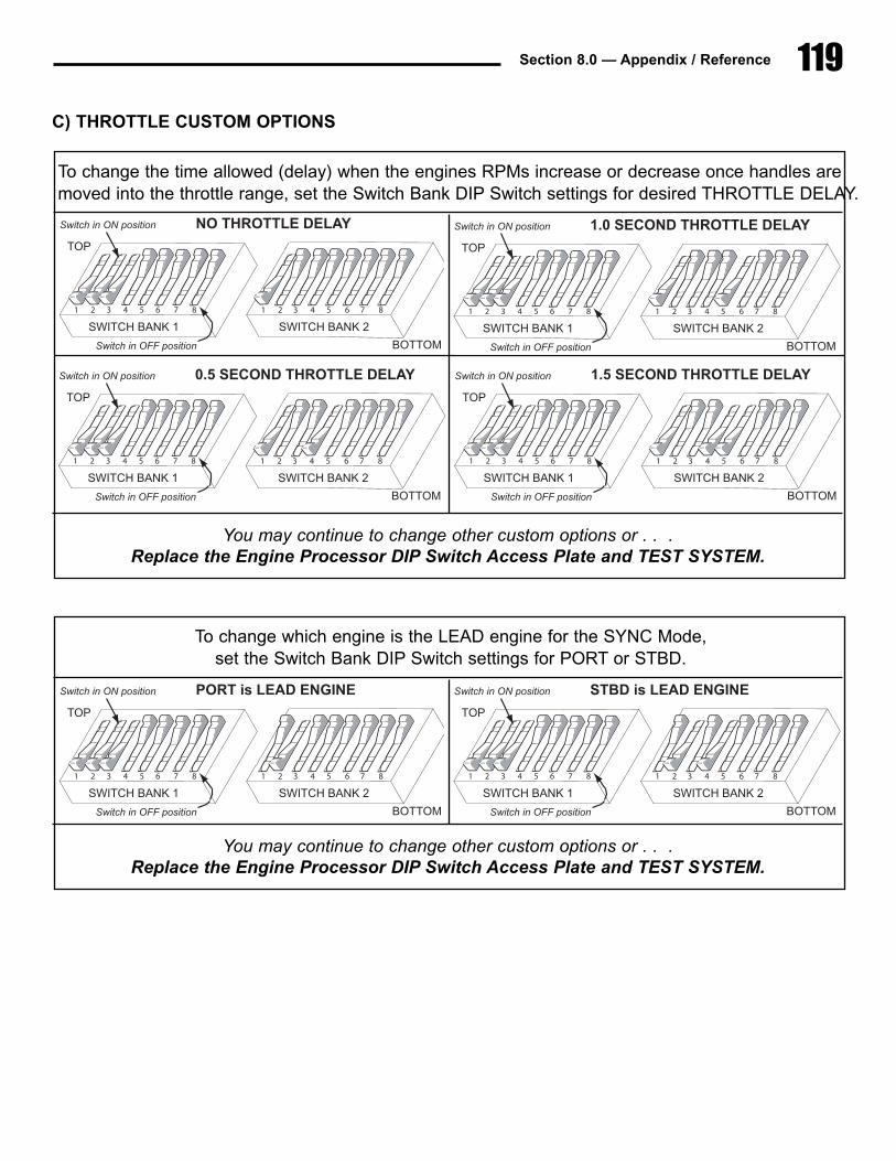
119Section 8.0 — Appendix / Reference
C) THROTTLE CUSTOM OPTIONS
To change the time allowed (delay) when the engines RPMs increase or decrease once handles aremoved into the throttle range, set the Switch Bank DIP Switch settings for desired THROTTLE DELAY.
6 7 831 5422 3 5 6 7 81 4
SWITCH�BANK�1 SWITCH�BANK�2
1�CONTROL�STATION
TOP
BOTTO
Switch�in�ON�position
S i h i OFF i i
You may continue to change other custom options or . . .Replace the Engine Processor DIP Switch Access Plate and TEST SYSTEM.
6 7 83 41 522 3 5 6 7 81 4
SWITCH�BANK�1 SWITCH�BANK�2
NO�THROTTLE�DELAY
TOP
BOTTOM
Switch�in�ON�position
Switch�in�OFF�position
6 7 83 41 522 3 5 6 7 81 4
SWITCH�BANK�1 SWITCH�BANK�2
1.0�SECOND�THROTTLE�DELAY
TOP
BOTTOM
Switch�in�ON�position
Switch�in�OFF�position
6 7 83 41 522 3 5 6 7 81 4
SWITCH�BANK�1 SWITCH�BANK�2
0.5�SECOND�THROTTLE�DELAY
TOP
BOTTOM
Switch�in�ON�position
Switch�in�OFF�position
6 7 83 41 522 3 5 6 7 81 4
SWITCH�BANK�1 SWITCH�BANK�2
1.5�SECOND�THROTTLE�DELAY
TOP
BOTTOM
Switch�in�ON�position
Switch�in�OFF�position
To change which engine is the LEAD engine for the SYNC Mode, set the Switch Bank DIP Switch settings for PORT or STBD.
6 7 831 5422 3 5 6 7 81 4
SWITCH�BANK�1 SWITCH�BANK�2
1�CONTROL�STATION
TOP
BOTTO
Switch�in�ON�position
S i h i OFF i i
You may continue to change other custom options or . . .Replace the Engine Processor DIP Switch Access Plate and TEST SYSTEM.
6 7 83 41 522 3 5 6 7 81 4
SWITCH�BANK�1 SWITCH�BANK�2
PORT�is�LEAD�ENGINE
TOP
BOTTOM
Switch�in�ON�position
Switch�in�OFF�position
6 7 83 41 522 3 5 6 7 81 4
SWITCH�BANK�1 SWITCH�BANK�2
STBD�is�LEAD�ENGINE
TOP
BOTTOM
Switch�in�ON�position
Switch�in�OFF�position
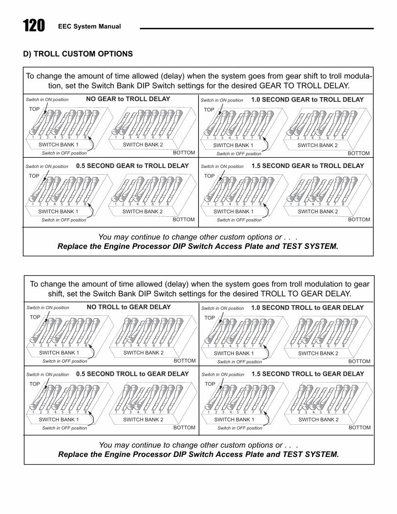
120 EEC System Manual
D) TROLL CUSTOM OPTIONS
To change the amount of time allowed (delay) when the system goes from gear shift to troll modula-tion, set the Switch Bank DIP Switch settings for the desired GEAR TO TROLL DELAY.
6 7 831 5422 3 5 6 7 81 4
SWITCH�BANK�1 SWITCH�BANK�2
1�CONTROL�STATION
TOP
BOTTO
Switch�in�ON�position
S i h i OFF i i
You may continue to change other custom options or . . .Replace the Engine Processor DIP Switch Access Plate and TEST SYSTEM.
6 7 83 41 522 3 5 6 7 81 4
SWITCH�BANK�1 SWITCH�BANK�2
NO�GEAR�to�TROLL�DELAY
TOP
BOTTOM
Switch�in�ON�position
Switch�in�OFF�position
6 7 83 41 522 3 5 6 7 81 4
SWITCH�BANK�1 SWITCH�BANK�2
1.0�SECOND�GEAR�to�TROLL�DELAY
TOP
BOTTOM
Switch�in�ON�position
Switch�in�OFF�position
6 7 83 41 522 3 5 6 7 81 4
SWITCH�BANK�1 SWITCH�BANK�2
0.5�SECOND�GEAR�to�TROLL�DELAY
TOP
BOTTOM
Switch�in�ON�position
Switch�in�OFF�position
6 7 83 41 522 3 5 6 7 81 4
SWITCH�BANK�1 SWITCH�BANK�2
1.5�SECOND�GEAR�to�TROLL�DELAY
TOP
BOTTOM
Switch�in�ON�position
Switch�in�OFF�position
To change the amount of time allowed (delay) when the system goes from troll modulation to gearshift, set the Switch Bank DIP Switch settings for the desired TROLL TO GEAR DELAY.
6 7 831 5422 3 5 6 7 81 4
SWITCH�BANK�1 SWITCH�BANK�2
1�CONTROL�STATION
TOP
BOTTO
Switch�in�ON�position
S i h i OFF i i
You may continue to change other custom options or . . .Replace the Engine Processor DIP Switch Access Plate and TEST SYSTEM.
6 7 83 41 522 3 5 6 7 81 4
SWITCH�BANK�1 SWITCH�BANK�2
NO�TROLL�to�GEAR�DELAY
TOP
BOTTOM
Switch�in�ON�position
Switch�in�OFF�position
6 7 83 41 522 3 5 6 7 81 4
SWITCH�BANK�1 SWITCH�BANK�2
1.0�SECOND�TROLL�to�GEAR�DELAY
TOP
BOTTOM
Switch�in�ON�position
Switch�in�OFF�position
6 7 83 41 522 3 5 6 7 81 4
SWITCH�BANK�1 SWITCH�BANK�2
0.5�SECOND�TROLL�to�GEAR�DELAY
TOP
BOTTOM
Switch�in�ON�position
Switch�in�OFF�position
6 7 83 41 522 3 5 6 7 81 4
SWITCH�BANK�1 SWITCH�BANK�2
1.5�SECOND�TROLL�to�GEAR�DELAY
TOP
BOTTOM
Switch�in�ON�position
Switch�in�OFF�position
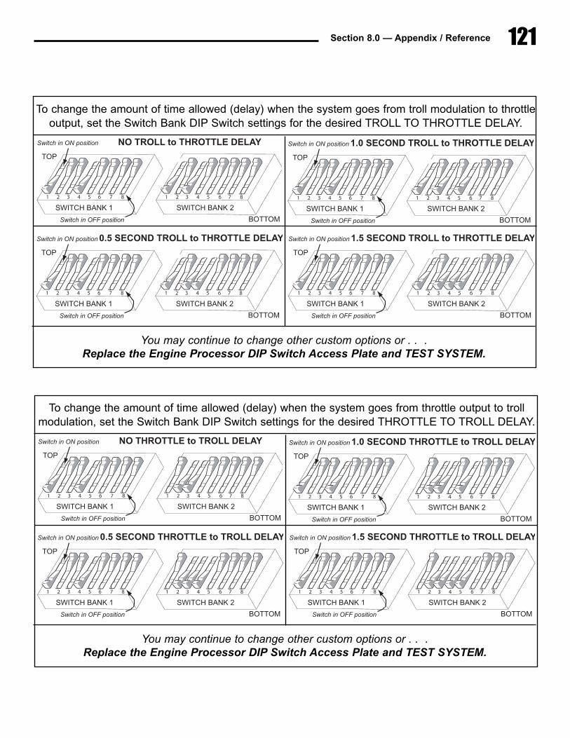
121Section 8.0 — Appendix / Reference
To change the amount of time allowed (delay) when the system goes from troll modulation to throttleoutput, set the Switch Bank DIP Switch settings for the desired TROLL TO THROTTLE DELAY.
6 7 831 5422 3 5 6 7 81 4
SWITCH�BANK�1 SWITCH�BANK�2
1�CONTROL�STATION
TOP
BOTTO
Switch�in�ON�position
S i h i OFF i i
You may continue to change other custom options or . . .Replace the Engine Processor DIP Switch Access Plate and TEST SYSTEM.
6 7 83 41 522 3 5 6 7 81 4
SWITCH�BANK�1 SWITCH�BANK�2
NO�TROLL�to�THROTTLE�DELAY
TOP
BOTTOM
Switch�in�ON�position
Switch�in�OFF�position
6 7 83 41 522 3 5 6 7 81 4
SWITCH�BANK�1 SWITCH�BANK�2
1.0�SECOND�TROLL�to�THROTTLE�DELAY
TOP
BOTTOM
Switch�in�ON�position
Switch�in�OFF�position
6 7 83 41 522 3 5 6 7 81 4
SWITCH�BANK�1 SWITCH�BANK�2
0.5�SECOND�TROLL�to�THROTTLE�DELAY
TOP
BOTTOM
Switch�in�ON�position
Switch�in�OFF�position
6 7 83 41 522 3 5 6 7 81 4
SWITCH�BANK�1 SWITCH�BANK�2
1.5�SECOND�TROLL�to�THROTTLE�DELAY
TOP
BOTTOM
Switch�in�ON�position
Switch�in�OFF�position
To change the amount of time allowed (delay) when the system goes from throttle output to trollmodulation, set the Switch Bank DIP Switch settings for the desired THROTTLE TO TROLL DELAY.
6 7 831 5422 3 5 6 7 81 4
SWITCH�BANK�1 SWITCH�BANK�2
1�CONTROL�STATION
TOP
BOTTO
Switch�in�ON�position
S i h i OFF i i
You may continue to change other custom options or . . .Replace the Engine Processor DIP Switch Access Plate and TEST SYSTEM.
6 7 83 41 522 3 5 6 7 81 4
SWITCH�BANK�1 SWITCH�BANK�2
NO�THROTTLE�to�TROLL�DELAY
TOP
BOTTOM
Switch�in�ON�position
Switch�in�OFF�position
6 7 83 41 522 3 5 6 7 81 4
SWITCH�BANK�1 SWITCH�BANK�2
1.0�SECOND�THROTTLE�to�TROLL�DELAY
TOP
BOTTOM
Switch�in�ON�position
Switch�in�OFF�position
6 7 83 41 522 3 5 6 7 81 4
SWITCH�BANK�1 SWITCH�BANK�2
0.5�SECOND�THROTTLE�to�TROLL�DELAY
TOP
BOTTOM
Switch�in�ON�position
Switch�in�OFF�position
6 7 83 41 522 3 5 6 7 81 4
SWITCH�BANK�1 SWITCH�BANK�2
1.5�SECOND�THROTTLE�to�TROLL�DELAY
TOP
BOTTOM
Switch�in�ON�position
Switch�in�OFF�position
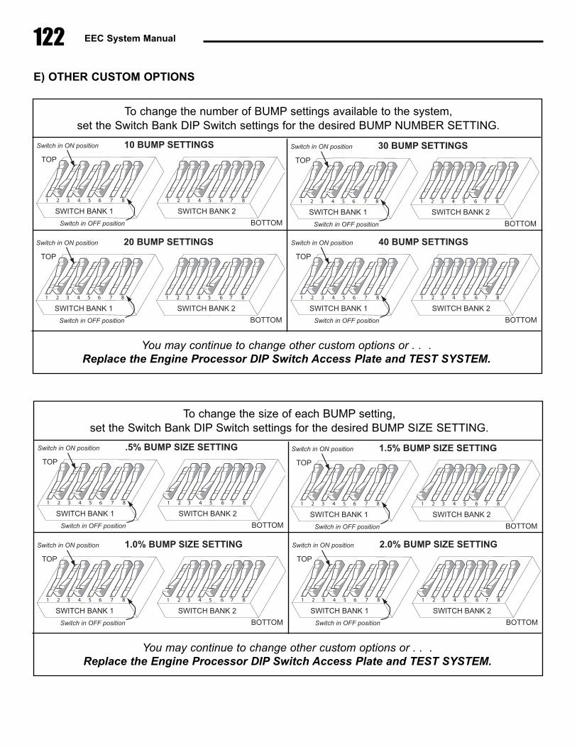
122 EEC System Manual
E) OTHER CUSTOM OPTIONS
To change the number of BUMP settings available to the system, set the Switch Bank DIP Switch settings for the desired BUMP NUMBER SETTING.
6 7 831 5422 3 5 6 7 81 4
SWITCH�BANK�1 SWITCH�BANK�2
1�CONTROL�STATION
TOP
BOTTO
Switch�in�ON�position
S i h i OFF i i
You may continue to change other custom options or . . .Replace the Engine Processor DIP Switch Access Plate and TEST SYSTEM.
6 7 83 41 522 3 5 6 7 81 4
SWITCH�BANK�1 SWITCH�BANK�2
10�BUMP�SETTINGS
TOP
BOTTOM
Switch�in�ON�position
Switch�in�OFF�position
6 7 83 41 522 3 5 6 7 81 4
SWITCH�BANK�1 SWITCH�BANK�2
30�BUMP�SETTINGS
TOP
BOTTOM
Switch�in�ON�position
Switch�in�OFF�position
6 7 83 41 522 3 5 6 7 81 4
SWITCH�BANK�1 SWITCH�BANK�2
20�BUMP�SETTINGS
TOP
BOTTOM
Switch�in�ON�position
Switch�in�OFF�position
6 7 83 41 522 3 5 6 7 81 4
SWITCH�BANK�1 SWITCH�BANK�2
40�BUMP�SETTINGS
TOP
BOTTOM
Switch�in�ON�position
Switch�in�OFF�position
To change the size of each BUMP setting, set the Switch Bank DIP Switch settings for the desired BUMP SIZE SETTING.
6 7 831 5422 3 5 6 7 81 4
SWITCH�BANK�1 SWITCH�BANK�2
1�CONTROL�STATION
TOP
BOTTO
Switch�in�ON�position
S i h i OFF i i
You may continue to change other custom options or . . .Replace the Engine Processor DIP Switch Access Plate and TEST SYSTEM.
6 7 83 41 522 3 5 6 7 81 4
SWITCH�BANK�1 SWITCH�BANK�2
.5%�BUMP�SIZE�SETTING
TOP
BOTTOM
Switch�in�ON�position
Switch�in�OFF�position
6 7 83 41 522 3 5 6 7 81 4
SWITCH�BANK�1 SWITCH�BANK�2
1.5%�BUMP�SIZE�SETTING
TOP
BOTTOM
Switch�in�ON�position
Switch�in�OFF�position
6 7 83 41 522 3 5 6 7 81 4
SWITCH�BANK�1 SWITCH�BANK�2
1.0%�BUMP�SIZE�SETTING
TOP
BOTTOM
Switch�in�ON�position
Switch�in�OFF�position
6 7 83 41 522 3 5 6 7 81 4
SWITCH�BANK�1 SWITCH�BANK�2
2.0%�BUMP�SIZE�SETTING
TOP
BOTTOM
Switch�in�ON�position
Switch�in�OFF�position
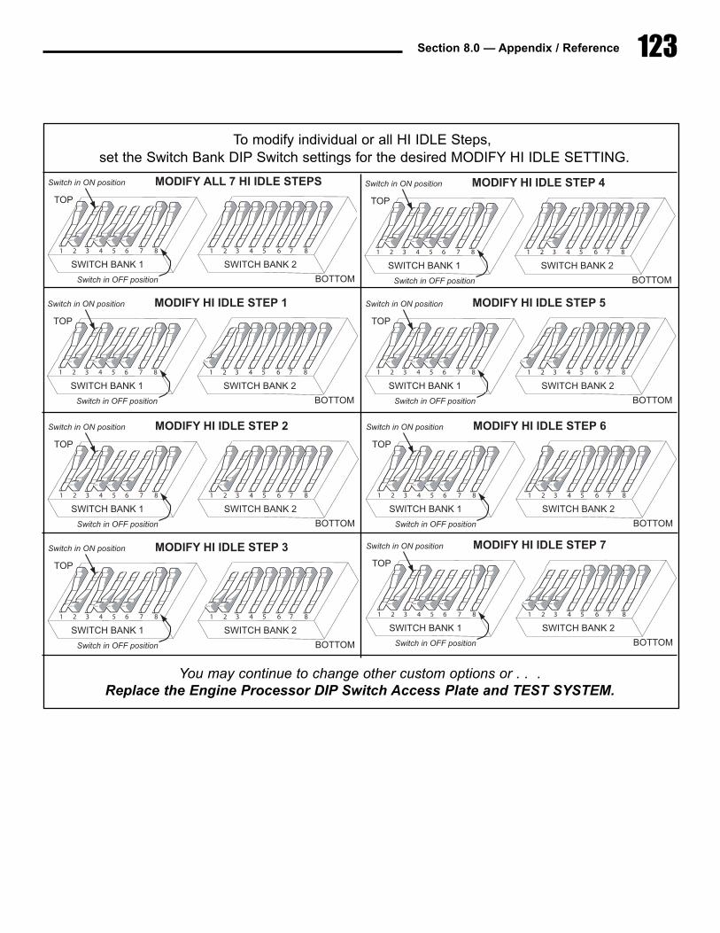
123Section 8.0 — Appendix / Reference
To modify individual or all HI IDLE Steps,set the Switch Bank DIP Switch settings for the desired MODIFY HI IDLE SETTING.
6 7 831 5422 3 5 6 7 81 4
SWITCH�BANK�1 SWITCH�BANK�2
1�CONTROL�STATION
TOP
BOTTO
Switch�in�ON�position
S i h i OFF i i
You may continue to change other custom options or . . .Replace the Engine Processor DIP Switch Access Plate and TEST SYSTEM.
6 7 83 41 522 3 5 6 7 81 4
SWITCH�BANK�1 SWITCH�BANK�2
MODIFY�ALL�7�HI�IDLE�STEPS
TOP
BOTTOM
Switch�in�ON�position
Switch�in�OFF�position
6 7 83 41 522 3 5 6 7 81 4
SWITCH�BANK�1 SWITCH�BANK�2
MODIFY�HI�IDLE�STEP�4
TOP
BOTTOM
Switch�in�ON�position
Switch�in�OFF�position
6 7 83 41 522 3 5 6 7 81 4
SWITCH�BANK�1 SWITCH�BANK�2
MODIFY�HI�IDLE�STEP�1
TOP
BOTTOM
Switch�in�ON�position
Switch�in�OFF�position
6 7 83 41 522 3 5 6 7 81 4
SWITCH�BANK�1 SWITCH�BANK�2
MODIFY�HI�IDLE�STEP�5
TOP
BOTTOM
Switch�in�ON�position
Switch�in�OFF�position
6 7 83 41 522 3 5 6 7 81 4
SWITCH�BANK�1 SWITCH�BANK�2
MODIFY�HI�IDLE�STEP�2
TOP
BOTTOM
Switch�in�ON�position
Switch�in�OFF�position
6 7 83 41 522 3 5 6 7 81 4
SWITCH�BANK�1 SWITCH�BANK�2
MODIFY�HI�IDLE�STEP�6
TOP
BOTTOM
Switch�in�ON�position
Switch�in�OFF�position
6 7 83 41 522 3 5 6 7 81 4
SWITCH�BANK�1 SWITCH�BANK�2
MODIFY�HI�IDLE�STEP�3
TOP
BOTTOM
Switch�in�ON�position
Switch�in�OFF�position
6 7 83 41 522 3 5 6 7 81 4
SWITCH�BANK�1 SWITCH�BANK�2
MODIFY�HI�IDLE�STEP�7
TOP
BOTTOM
Switch�in�ON�position
Switch�in�OFF�position

124 EEC System Manual
To modify the size of each HI IDLE Step,set the Switch Bank DIP Switch settings for the desired SIZE OF HI IDLE SETTING.
6 7 831 5422 3 5 6 7 81 4
SWITCH�BANK�1 SWITCH�BANK�2
1�CONTROL�STATION
TOP
BOTTO
Switch�in�ON�position
S i h i OFF i i
CHART CONTINUED ON NEXT PAGE . . .
6 7 83 41 522 3 5 6 7 81 4
SWITCH�BANK�1 SWITCH�BANK�2
0%�of�THROTTLE�RANGE
TOP
BOTTOM
Switch�in�ON�position
Switch�in�OFF�position
6 7 83 41 522 3 5 6 7 81 4
SWITCH�BANK�1 SWITCH�BANK�2
5%�of�THROTTLE�RANGE
TOP
BOTTOM
Switch�in�ON�position
Switch�in�OFF�position
6 7 83 41 522 3 5 6 7 81 4
SWITCH�BANK�1 SWITCH�BANK�2
0.5%�of�THROTTLE�RANGE
TOP
BOTTOM
Switch�in�ON�position
Switch�in�OFF�position
6 7 83 41 522 3 5 6 7 81 4
SWITCH�BANK�1 SWITCH�BANK�2
6%�of�THROTTLE�RANGE
TOP
BOTTOM
Switch�in�ON�position
Switch�in�OFF�position
6 7 83 41 522 3 5 6 7 81 4
SWITCH�BANK�1 SWITCH�BANK�2
1%�of�THROTTLE�RANGE
TOP
BOTTOM
Switch�in�ON�position
Switch�in�OFF�position
6 7 83 41 522 3 5 6 7 81 4
SWITCH�BANK�1 SWITCH�BANK�2
8%�of�THROTTLE�RANGE
TOP
BOTTOM
Switch�in�ON�position
Switch�in�OFF�position
6 7 83 41 522 3 5 6 7 81 4
SWITCH�BANK�1 SWITCH�BANK�2
2%�of�THROTTLE�RANGE
TOP
BOTTOM
Switch�in�ON�position
Switch�in�OFF�position
6 7 83 41 522 3 5 6 7 81 4
SWITCH�BANK�1 SWITCH�BANK�2
10%�of�THROTTLE�RANGE
TOP
BOTTOM
Switch�in�ON�position
Switch�in�OFF�position
6 7 83 41 522 3 5 6 7 81 4
SWITCH�BANK�1 SWITCH�BANK�2
3%�of�THROTTLE�RANGE
TOP
BOTTOM
Switch�in�ON�position
Switch�in�OFF�position
6 7 83 41 522 3 5 6 7 81 4
SWITCH�BANK�1 SWITCH�BANK�2
15%�of�THROTTLE�RANGE
TOP
BOTTOM
Switch�in�ON�position
Switch�in�OFF�position
6 7 83 41 522 3 5 6 7 81 4
SWITCH�BANK�1 SWITCH�BANK�2
4%�of�THROTTLE�RANGE
TOP
BOTTOM
Switch�in�ON�position
Switch�in�OFF�position
6 7 83 41 522 3 5 6 7 81 4
SWITCH�BANK�1 SWITCH�BANK�2
20%�of�THROTTLE�RANGE
TOP
BOTTOM
Switch�in�ON�position
Switch�in�OFF�position
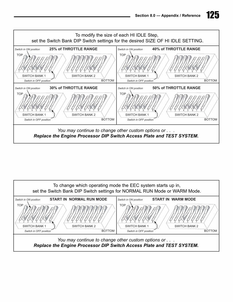
125Section 8.0 — Appendix / Reference
To modify the size of each HI IDLE Step,set the Switch Bank DIP Switch settings for the desired SIZE OF HI IDLE SETTING.
6 7 831 5422 3 5 6 7 81 4
SWITCH�BANK�1 SWITCH�BANK�2
1�CONTROL�STATION
TOP
BOTTO
Switch�in�ON�position
S i h i OFF i i
You may continue to change other custom options or . . .Replace the Engine Processor DIP Switch Access Plate and TEST SYSTEM.
6 7 83 41 522 3 5 6 7 81 4
SWITCH�BANK�1 SWITCH�BANK�2
25%�of�THROTTLE�RANGE
TOP
BOTTOM
Switch�in�ON�position
Switch�in�OFF�position
6 7 83 41 522 3 5 6 7 81 4
SWITCH�BANK�1 SWITCH�BANK�2
40%�of�THROTTLE�RANGE
TOP
BOTTOM
Switch�in�ON�position
Switch�in�OFF�position
6 7 83 41 522 3 5 6 7 81 4
SWITCH�BANK�1 SWITCH�BANK�2
30%�of�THROTTLE�RANGE
TOP
BOTTOM
Switch�in�ON�position
Switch�in�OFF�position
6 7 83 41 522 3 5 6 7 81 4
SWITCH�BANK�1 SWITCH�BANK�2
50%�of�THROTTLE�RANGE
TOP
BOTTOM
Switch�in�ON�position
Switch�in�OFF�position
To change which operating mode the EEC system starts up in, set the Switch Bank DIP Switch settings for NORMAL RUN Mode or WARM Mode.
6 7 831 5422 3 5 6 7 81 4
SWITCH�BANK�1 SWITCH�BANK�2
1�CONTROL�STATION
TOP
BOTTO
Switch�in�ON�position
S i h i OFF i i
You may continue to change other custom options or . . .Replace the Engine Processor DIP Switch Access Plate and TEST SYSTEM.
6 7 83 41 522 3 5 6 7 81 4
SWITCH�BANK�1 SWITCH�BANK�2
START�IN��NORMAL�RUN�MODE
TOP
BOTTOM
Switch�in�ON�position
Switch�in�OFF�position
6 7 83 41 522 3 5 6 7 81 4
SWITCH�BANK�1 SWITCH�BANK�2
START�IN��WARM�MODE
TOP
BOTTOM
Switch�in�ON�position
Switch�in�OFF�position
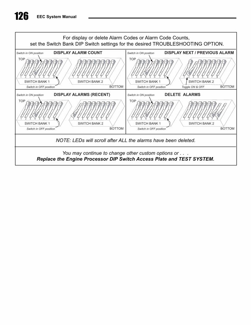
126 EEC System Manual
For display or delete Alarm Codes or Alarm Code Counts,set the Switch Bank DIP Switch settings for the desired TROUBLESHOOTING OPTION.
6 7 831 5422 3 5 6 7 81 4
SWITCH�BANK�1 SWITCH�BANK�2
1�CONTROL�STATION
TOP
BOTTO
Switch�in�ON�position
S i h i OFF i i
You may continue to change other custom options or . . .Replace the Engine Processor DIP Switch Access Plate and TEST SYSTEM.
NOTE: LEDs will scroll after ALL the alarms have been deleted.
6 7 83 41 522 3 5 6 7 81 4
SWITCH�BANK�1 SWITCH�BANK�2
DISPLAY�ALARM�COUNT
TOP
BOTTOM
Switch�in�ON�position
Switch�in�OFF�position
6 7 83 41 522 3 5 6 7 81 4
SWITCH�BANK�1 SWITCH�BANK�2
DISPLAY�NEXT�/�PREVIOUS�ALARM
TOP
BOTTOM
Switch�in�ON�position
Switch�in�OFF�position Toggle�ON�&�OFF
6 7 83 41 522 3 5 6 7 81 4
SWITCH�BANK�1 SWITCH�BANK�2
DISPLAY�ALARMS�(RECENT)
TOP
BOTTOM
Switch�in�ON�position
Switch�in�OFF�position
6 7 83 41 522 3 5 6 7 81 4
SWITCH�BANK�1 SWITCH�BANK�2
DELETE��ALARMS
TOP
BOTTOM
Switch�in�ON�position
Switch�in�OFF�position

127Section 8.0 — Appendix / Reference