Install - Cover and Contents v1 3 - Home - Glendinning Products€¦ · · 2016-02-04B. Engine...
56
GLENDINNING ELECTRONIC ENGINE CONTROLS INSTALLATION MANUAL Ver. 1.3 (includes update for software version 5) GLENDINNING MARINE PRODUCTS, INC. 740 Century Circle Conway, SC 29526 843-399-6146 FAX 843-399-5005 website: www.glendinningprods.com
Transcript of Install - Cover and Contents v1 3 - Home - Glendinning Products€¦ · · 2016-02-04B. Engine...

GLENDINNING ELECTRONIC ENGINE CONTROLS
INSTALLATION MANUAL
Ver. 1.3
(includes update for software version 5)
GLENDINNING MARINE PRODUCTS, INC. 740 Century Circle Conway, SC 29526 843-399-6146 FAX 843-399-5005
website: www.glendinningprods.com

TABLE OF CONTENTS Print Date: 9/3/2003 File: Install - Cover and Contents (v1_3).doc
GLENDINNING MARINE PRODUCTS, INC. Electronic Engine Control System Installation Manual - Revision 1.3
Page Number Table of Contents
Introduction – Pre-installation Planning
1
1.0 Cable Connections
8
2.0 Engine Room Component Installation 2.1 Actuator Installation - Throttle / Gear / Troll Valve 2.2 Control Cable Installation–Throttle / Gear / Troll Valve 2.3 Engine Processor Installation 2.4 Tachometer Sender Installation (mechanical) 2.5 Engine Room wiring connections
A. Actuator Harness B. Engine Processor (EP) Power Supply / Bonding Wire C. Start Interlock D. Tachometer Sender Installation (electrical) E. Remote Power switch (Option)
9
3.0 Topside Component Installation 3.1 Remote Station Control head
3.2 Main Station Control Head (w/ mechanical backup interface) 3.3 Mechanical Backup Control Cable Installation 3.4 Station Processor Installation 3.5 Station Processor to Engine Processor Connection Cables
23
4.0 System Calibration 4.1 System Preparation (for Calibration) 4.2 Entering Calibration Mode 4.3 Actuator Positioning 4.4 Handle Validation 4.5 Exiting Calibration Mode 4.6 Calibration verification
33
5.0 System Inspection (Checklist) / Operational Test
46

TABLE OF CONTENTS File: Install - Cover and Contents (v1_3).doc Print Date: 9/3/2003
6.0 Appendices / References
6.1 Component Dimensions A. Actuator – regular B. Actuator – with CAT TPS mounted (2 pages) C. Control Head (with mechanical backup) D. Control Head (electronic only) E. Side Mount Control Head (3 pages) F. Engine Processor / Station Processor
6.2 Mechanical Drive Adapters A. #120 Mechanical Drive Adapter
B. # 130 Mechanical Drive Adapter C. 454 Mechanical Drive Adapter
6.3 Wiring Diagram 6.4 Cutout Templates for Control Heads

PRE-INSTALLATION PLANNING Page 1 File:Install - Pre-installation Planning.doc Print Date: 9/3/2003
ELECTRONIC ENGINE CONTROL SYSTEM Pre-Installation Planning
Before beginning the installation of the Glendinning Electronic Engine Control (EEC), proper consideration and pre-planning should be given to several very important parts of the EEC system. Proper planning of the installation will help to help to insure that the EEC system will operate correctly and within specification. Failing to properly plan will decrease the reliability of the EEC system and possibly disable some of the product's inherent safety features. The two most critical parts of the EEC system installation are the following:
Component Location – In order for the integrated mechanical backup system to work properly, and to maximize the overall reliability of the EEC system, the proper location of the Actuators, Engine Processor, and Mechanical backup control head is extremely important.
EEC system power supply – The EEC system includes a reliability feature called “dual battery inputs”. One of the most critical factors in determining the reliability of any electrical equipment is providing a solid source of electrical power. In order to increase the probability that the Electronic Engine Control will be able to receive a solid source of electrical power, the EEC system has been designed to power inputs from two (2) independent batteries. Failing to properly provide power from (2) independent battery sources will disable this important safety feature.
COMPONENT LOCATIONS The most important pre-installation decisions which must be made are the proper locations for several of the EEC components, specifically the Actuators, Mechanical Backup Control Head, and Engine Processor. Properly installed, the EEC system will work according to specifications. Improperly installed, overall reliability of the EEC system will be reduced and some system features, such as mechanical backup operation, will be degraded. Actuator Location
It cannot be emphasized strongly enough: the location of the EEC system actuators is the most important factor in the satisfactory operation of the integrated mechanical backup system. (If no mechanical backup system is used, or if the system is "non-integrated", actuator location is less important.) This is because the location of the Actuators has a direct impact on the routing of the control cables. In general, and almost without exception, there is a direct connection between good routing of the control cables and the operation of the mechanical backup system - good control cable routing will result in good mechanical backup operation, bad control cable routing will result in bad mechanical backup operation. Some factors which contribute to good Actuator location are the following:
- Straight cable runs with the minimum number of bends – The most efficient cable configuration is a straight cable run with no bends. Although this will yield maximum cable efficiency, it is not practical in a typical installation. Therefore, to maximize cable efficiency, the Actuator locations should be chosen which will reduce or eliminate the total number of bends in the control cables. (This includes the control cables which connect the Actuator to the engine / gear as well as the mechanical backup cables).
- Cable bends should have a large radius – The claims of the control cable manufacturers notwithstanding, control cables are far more efficient with larger diameter bends rather than

Page 2 PRE-INSTALLATION PLANNING File:Install - Pre-installation Planning.doc Print Date: 9/3/2003
smaller diameter. Where possible, large, sweeping turns should be used rather than smaller, tighter turns.
As an aid in determining the best location for the EEC system actuators, several drawings have been prepared which depict some typical installations. Please review these drawings, which are located at the end of this section, to see if any of these layouts would be applicable to your specific installation.
NOTE As part of its service to its customers, Glendinning Marine Products, Inc. offers, at no charge to the customer, a plan review service for EEC system installations. In order to take advantage of this free service, fax or mail a sketch of the proposed installation to our EEC Application Manager. Although this sketch can be very simple, it should show the general arrangement of the engine and gearbox, points of attachment for the control cables, location for mechanical backup cable entry into the engine room, and proposed location of EEC system components.
Regarding Control Cables To ensure good operation of the Engine Control mechanical backup system it is important that good quality
control cables be used. Although the EEC system components – Actuators and Mechanical backup control head – are designed to accommodate any standard Type 33C control cable, there are many grades and qualities of control cables available on the market. Like the position of the Actuators described above, the quality of the control cables will have a direct impact on the function of the mechanical backup after the installation is completed. In general, the use of standard quality “Morse Red Jaket” cables (or Teleflex equivalent) is not recommended. Some installers have had acceptable result using “Morse Supreme” cables (or Teleflex equivalent). Our recommendation, based on decades of experience with control cables, is to use Type 95 control cables manufactured by NW Controls (Harleysville, PA). Our testing has found these cables to have consistently the highest efficiency, smoothest operation, and greatest flexibility of any control cable on the market. NW Control cables are available from Glendinning Marine Products, Lewis Marine Supply, or other marine distributors.
On aftermarket installations, it is generally not recommended to reuse the existing control cables for the mechanical backup system. Mechanical Backup Control Head
Determining a good location for the mechanical backup control head is important, although the location of this component is frequently pre-determined by the boat owner or yacht designer. Two issues must be considered in the installation of the mechanical backup cables:
- Clearance for mechanical backup levers – Several levers are mounted below and on the side of the mechanical backup control head. In some cases, there is insufficient clearance below the control head to allow for unimpeded movement of these levers or for their installation or servicing.
- Control cable routing – The issues discussed above regarding control cable routing to the actuators also apply here. Large sweeping bends should be used rather than tight turns.
Engine Processor
The following considerations should be kept in mind when identifying a good location for the Engine Processor:
- Environmental conditions – The Engine Processor should be mounted in an area that is relatively dry and cool. Although the Engine Processor electronic components are reasonably well-sealed from moisture, the product enclosure is not designed for constant direct contact with water. Since the longevity of electronic components is reduced in high temperature environments, it is best to find an area of the engine compartment that is not

PRE-INSTALLATION PLANNING Page 3 File:Install - Pre-installation Planning.doc Print Date: 9/3/2003
exposed to temperature extremes. Although the Engine Processor has been designed for installation in the engine compartment, the design of the product does allow it to be installed external to the engine compartment, as long as the wire length from the Actuators is 20’ or less. The Engine Processor should be installed where there is some air movement or ventilation
- Accessible – During system calibration or troubleshooting, it will be necessary for the installer or repair technician to have access to the internal connections of the Engine Processor. In view of this, the Engine Processor should be mounted in a relatively accessible area.
- The Engine Processor can be mounted in any orientation – on the overhead or deck, or on the bulkhead.
Example installation diagrams The following drawing illustrates a typical location for the Actuators where the mechanical backup cables enter the engine compartment at the aft rear corners. The Actuators are mounted on the outboard hull shell, with the Actuator control cable mounting plate oriented toward the aft end of the boat. The control cables to the engine and gear make a “rear entry” and are connected to the Actuators through a single 180 degree bend.
Mechanical BackupControl Cables
Gear ControlCable
Gear ControlCable
Mechanical BackupControl Cables
Throttle ControlCable
Throttle ControlCable
Aft-Starboard and Port Entry Points

Page 4 PRE-INSTALLATION PLANNING File:Install - Pre-installation Planning.doc Print Date: 9/3/2003
The following drawing illustrates a typical location for the Actuators where the mechanical backup cables enter the engine compartment at one of the forward corners. The Actuators are mounted on the forward bulkhead, with the Actuator control cable mounting plate oriented toward the side of the engine compartment where the cables enter. The control cables to the engine and gear make a “front entry” to the engine governor and are connected to the Actuators through a one or two 90 degree bends.
Forward-Starboard Entry Point
Gear ControlCable
Throttle ControlCable
Gear ControlCable
Throttle ControlCable
Mechanical BackupControl Cables

PRE-INSTALLATION PLANNING Page 5 File:Install - Pre-installation Planning.doc Print Date: 9/3/2003
The following drawing illustrates a typical location for the Actuators where the mechanical backup cables enter the engine compartment at the forward corners. The Actuators are mounted on the overhead of the engine compartment at each rear corner, with the Actuator control cable mounting plate oriented toward the forward end of the engine compartment where the cables enter. The control cables to the engine and gear make a “rear entry” to the engine governor and are connected to the Actuators through a one or two 90 degree bends.
Gear ControlCable
Throttle ControlCable
Mid-Starboard and Port Entry Points
Mechanical BackupControl Cables
Mechanical BackupControl Cables
Gear ControlCable
Throttle ControlCable
Mechanical BackupControl Cables

Page 6 PRE-INSTALLATION PLANNING File:Install - Pre-installation Planning.doc Print Date: 9/3/2003
POWER SUPPLY In the installation of any electronic device, the source of power is one of the most important factors to consider during the installation. The Glendinning Electronic Engine Control has a unique and very reliable power supply system which, if the system is properly installed, greatly improves the overall reliability of the engine control system. One of the significant features of the power supply system the “dual battery input” – that is, the Engine Control provides for the connection of two independent sources of DC power. During normal operation, the Engine Control system will draw power from both power sources. In the event one of those power sources fail – due to battery failure, battery charger failure, or some other electrical distribution failure - the Engine Control is designed to run off a single DC power source, switching over automatically to the power source that is supplying the higher voltage. Of course, both power sources are completely isolated from the other. We believe that this concept of “dual battery inputs” provides a very important backup to a very critical part of the EEC system. In its most simple form, the dual battery schematic is as follows:
Some points which should be considered in the installation of the EEC power supply system are the following: Battery power should be drawn from 2 independent sources – In a typical boat, the DC power distribution system is designed to take power from a single battery source and then distribute it to the various equipment that require power. Although the battery source can usually be selected from one of several batteries, the DC distribution panel in not able to provide for the supply of power from 2 independent sources to any single device. Therefore, providing power to the EEC system from the DC distribution is usually not a good idea.
D.C. POWER INPUT
BATTERY(PORT)
BATTERY (STB)
+
BLACK (12 AWG)*RED (12 AWG)*
RED (12 AWG)*
Common DCground point
BREAKER BREAKER25A25A
Power Switch Relay Box
(optional)
EECPower Switch (optional)
(18 AWG)
+
Engine ProcessorEngine RoomMain Station

PRE-INSTALLATION PLANNING Page 7 File:Install - Pre-installation Planning.doc Print Date: 9/3/2003
In other boats, several batteries are arranged in parallel. Obviously, these batteries are not independent – that is, the voltage observed at one battery terminal will be the same at the other battery terminal. It is important that each battery source be completely independent of the other. Draw power from the battery as close to the battery positive terminal as possible – It cannot be overemphasized that providing a secure, uninterrupted source of power to the EEC system is vitally important to the reliable operation of the control system. For this reason, it is best that the EEC power be drawn as close as possible to the battery positive terminal, without have various components which may interrupt the flow of current to the control system Circuit protection – Per the ABYC guidelines, some type of current protection – circuit breaker or fuse - must be installed within 7 inches (17 cm) of the connection to the source of power. It is very important to understand that circuit protection is installed for the protection of the wire, not the EEC system. The EEC system has its own internal current protection and does not need any external fuse. However, the wire which connects the EEC to the boat power must be protected in case of chafing or other damage. In order to not limit power to the EEC system during normal operation, a minimum 25 Amp fuse or circuit breaker must be installed. (If a 30 Amp fuse or circuit breaker are used, then it is necessary that 10 AWG wire - or larger - is used to connect the EEC system to its power source).
NOTE In order to follow the two recommendations above – draw power close to battery positive terminal, and provide circuit protection for the interconnecting wiring – it is normal that the current protection – fuse or circuit breaker - will be physically located in the engine compartment. However, it is inconvenient to require the boat owner to have to go to the engine compartment to start up the Engine Control system each time that he / she wishes to use the boat. For this reason, Glendinning Marine Products has an optional “Power Switch Relay Unit” (PSRU) which allows the boat owner to remotely turn on or turn off the engine control system from the helm station. When the PSRU is used, the EEC circuit protection is typically left in the “ON” position. The PSRU only requires that a small (2 conductor, 18 gauge) wire be run from the engine compartment to the helm station. For more details, see Section 2.5-E of the manual.
Battery ground – The dual battery system requires that the battery positive terminals be at roughly the same voltage. In order for the battery positive terminals to be at the same voltage, it is necessary that the negative terminals of the batteries be connected at some common point. This is normal marine electrical practice and is specified in the ABYC voluntary guidelines. Prior to the final electrical hookup of the EEC system, the installer should verify that the battery ground terminals are connected at some common point.

Page 8 CABLE CONNECTIONS (ENGINE / TRANSMISSION) File: Install - Section 1.doc Print Date: 9/3/2003
1.0 Cable Travel Direction (Engine / Transmission) Prior to installation of the Electronic Engine Control (EEC) system, it is vital to determine the actual direction of travel of the control cables that connect to the engine governor and transmission control levers. Check the following items and write them in the space provided - this information will be needed later for EEC system calibration and for the connection of the mechanical backup cables.
NOTE Failure to obtain and enter this information correctly may result in incorrect system calibration, incorrect connection of the mechanical backup cables, and extra (unnecessary) work in redoing the control cable connections at the end of the installation. 1.1 Direction of transmission gear lever movement. Does mechanical cable PULL or PUSH on transmission gear control lever to obtain ahead gear? PORT ENGINE STARBOARD ENGINE To Engage Ahead Gear:
Cable will pull or push lever? To Engage Ahead Gear:
Cable will pull or push lever?
1.2 Direction of engine governor lever movement. Does mechanical cable PULL or PUSH on engine governor / throttle lever to increase engine speed? PORT ENGINE STARBOARD ENGINE To increase engine speed:
Cable will pull or push lever? To increase engine speed:
Cable will pull or push lever?
1.3 Direction of transmission troll lever movement. (If installed) Does mechanical cable PULL or PUSH on transmission troll valve control lever for full (100%) lock-up? PORT ENGINE STARBOARD ENGINE For Full Lock-Up:
Cable will pull or push lever? For Full Lock-Up
Cable will pull or push lever?

INSTALLATION - Engine Compartment Components Page 9 File: Install - Section 2.doc Print Date: 09/03/03
2.0 Installation of the engine room components 2.1 Actuator Installation
A. The primary factor in choosing a location for the actuators is finding a location that results in the shortest, most direct path for the push-pull cable that connects each actuator to the transmission and engine governor. In general, for engines where the control cable travels aft from the engine governor / throttle lever, the throttle actuator will be mounted in the aft section of the engine room. Conversely, for engines where the control cable heads forward from the engine governor lever, the actuator will be mounted toward the forward end of the engine room. In general, the length of the control cable from each actuator to the transmission and engine governor should not be greater than 10 feet and 180 total degrees of bend. (Longer lengths may be used after review and approval of the physical layout of the product installation by Glendinning Marine Products).
B. A second important factor which should be considered in correctly positioning the actuators is the routing of the mechanical backup cables. The shortest and most direct routing of the mechanical backup cables is important for smooth and easy operation of the mechanical backup system. C. Other factors which should be considered are: • The actuators can be mounted in any orientation - on the bulkhead, overhead, or
deck. The actuators should NOT be mounted on the engine. • Control cable length. The push-pull cables between Actuator and Engine Throttle or
Gear control lever should be no longer than 10 feet (unless installation layout is approved by Glendinning Marine Products).
NOTE The proper location of the Gear / Throttle Actuators is the most critical decision that must be made during the installation process. Failure to properly locate the actuators may cause degradation in system performance, premature failure of the actuator, or difficulty with the operation of mechanical backup system. Therefore, great care must be taken to ensure that the actuators are located in the best location possible.
One reason why a short cable to the engine governor is critical has to do with engine synchronization. In order to accurately synchronize one engine to the other, it is necessary to position the governor with an accuracy of less than five thousandths (0.005") of an inch. Any unnecessary bend in the control cable to the governor lever, or using a cable that is longer than necessary, will result in lost motion between the actuator and engine, causing a reduction in synchronization accuracy. This greater length will also increase the difficulty in controlling the engine governor using the mechanical backup system.
NOTE: Push-Pull control cables must be run straight for 9 – 12” from the mounting clamp point before making any bends.

Page 10 INSTALLATION – Engine Compartment Components Print Date: 09/03/03 File: Install - Section 2.doc
• The actuators should be protected from direct exposure to water or excessive heat. The Glendinning EEC actuator has been carefully designed to withstand exposure to saltwater normally encountered in an engine room and resist the effects of marine corrosion. However, installing the actuator in a location that subjects it to excessive saltwater exposure will cause premature wear and increase the possibility of system failure. Care should be taken to not locate the actuator near engine room vents, stern tube packing glands or other sources of saltwater spray. Shielding the actuator from sources of excessive heat, such as the engine exhaust manifolds, should also be taken into account.
• Maintainability - The actuator should be located in a position that is accessible for control cable adjustments.
Mounting the actuators
7.38"(187 mm)
Gear / Throttle Actuator
Start Interlock Switch
Gear ActuatorCoupler Plates
Throttle ActuatorCoupler Plates
Top plate (away from Actuator) - Mechanical backup cable
Middle plate Control cable to engine / gear
Bottom plate (nearest Actuator) Linkage to Actuator piston
Actuator Piston (2x) - one for throttle - one for gear
Solenoid (to engage / disengage electronic operation)
NOTE - Coupler Plates
8.38"(213 mm)
between mounting holes
2.25" (57 mm)
4.63" (117 mm) between
mounting holes
.31" dia. (8 mm) Mounting Holes4 holes
Mechanical Backup Cables to Control Head
Cable toTransmission Lever
Cable toEngine GovernorLever
9.00"(229 mm)
12.50"(318 mm)
NOTE:Wiring Harness to EP: 20' long (6 meters)Material : Aluminum Gold Anodized & Stainless SteelWeight : 28 lbs. (13 kg) (one mounted near each engine)

INSTALLATION - Engine Compartment Components Page 11 File: Install - Section 2.doc Print Date: 09/03/03
A. The actuators should be securely attached to the boat structure, using (4) 1/4" (7mm) machine bolts or lag screws. If using lag screws, screw length should be no less than 1 1 ½” (40mm). If using machine bolts, lockwashers or locknuts must be used. 2.2 Control Cable Installation – Actuator to throttle / gear / troll lever
A. Using standard Type 33C cable clamps and shims, mount the throttle / gear / troll lever control cables in their respective locations on the engine and transmission. Mount cables using cable clamps only - do not connect the cable ends to the control levers at this time. NOTE: Although 43c cables can be installed with our system, we recommend premium grade, Type 33C control cables as the best cable choice. B. Install terminal eyes on the end of each control cable, ensuring that the tip of the cable protrudes from the threaded portion of the metal terminal eye or that you have at least ½” (13 mm) of thread engagement. Do not tighten the terminal eye locknuts yet. C. Compare the travel of each control cable to its associated lever at the transmission and engine. Ensure that each control cable has "over-travel" or that the cable is able to travel farther than the lever that it will be attached to. Check this for both ends of travel. If the control cable will not "over-travel" in both directions, adjustments will have to be made: • If 1/4” or less adjustment is required, the terminal
eye on the end of the cable may be screwed on or off the cable end. Terminal eye thread engagement on the control cable end must never be less than 1/4”.
• If more than 1/4” inch adjustment is necessary to achieve correct over-travel, the cable clamp position on the engine or transmission will have to be moved.
Once correct control cable over-travel is verified, connect the terminal eye of each control cable to the engine governor / throttle and transmission lever and install the pivot pin cotter pins or clips. Tighten the control cable terminal eye jam nuts.
NOTE This section describes the installation and connection of the control cables to the engine governor and gear control lever. This connection must be properly made before control cables are connected to the EEC system Actuators.
NOTE In some cases, sufficient over-travel will not be able to be obtained even with adjustment of the cable clamp holder. This is caused by the connection point on the engine or transmission lever (normally called the pivot pin) being too far away from the shaft that the lever is connected to. In these cases, the pivot pin will have to be moved closer to the shaft (the “fulcrum point”) in order to shorten the pivot pin travel. This will give you the correct over-travel required. The recommended length of travel of the control lever pivot pin should be approximately 2 1/2” to 2-3/4”.

Page 12 INSTALLATION – Engine Compartment Components Print Date: 09/03/03 File: Install - Section 2.doc
D. After the control cable terminal eyes are attached to the control levers on the engine governor and transmission, measure the amount of travel for each control cable. Do this measurement at the actuator end of the control cable. (This is the distance that the cable will travel when the engine or transmission control lever is moved from one mechanical stop to the other. Record the information below – this information is needed in order to determine the correct cable connection on the Actuator coupler plates. PORT ENGINE STARBOARD ENGINE
Control cable Length of travel Control Cable Length of travel Throttle Throttle Gear Gear
Troll valve Troll valve
E. Once the control cables are properly attached to the engine governor / throttle and transmission control levers as described above in paragraphs A, B, and C, they may be connected to the Actuator levers as described below in paragraphs F, G, H and I. The following summarizes this process:
Paragraph F - Select the correct control cable mounting location on the Actuator, depending on the length of control lever / control cable travel.
Paragraph G - Move top "coupler plate" on Actuator out of the way to access middle "coupler plate".
Paragraph H - Select the correct coupler plate connection hole to be used, depending on length of control cable travel.
Paragraph I - Adjust control cable terminal prior to attaching to Actuator coupler plate F. Mount the engine / transmission control cables to the proper control cable mounting location on the actuator. There are two possible mounting locations on the actuator for the control cables depending on the length of control cable travel – the distance measured in paragraph D. above. For control cable travel between 1-1/2” and 2-3/16”, mount the control cable in the SHORT Travel Mounting location. For control cable travel between 2-1/4” and 3-1/8”, mount the control cable in the LONG Travel Mounting location. (See the following drawing for clarification). Use the middle set of holes in each mounting location slot to mount the cable.

INSTALLATION - Engine Compartment Components Page 13 File: Install - Section 2.doc Print Date: 09/03/03
G. Swing top coupler plate out of way to expose middle coupler plate. Once the cables are mounted on the Actuator in the correct mounting location and the clamp screws are tightened, attach the control cables to the actuator coupler plates. For the engine / transmission control cables, use the middle set of plates on the actuator coupler assembly. To gain access to the middle plates, line up all three (3) plates (drawing A below) and then push in on the ½” round coupler pin in the middle of the coupler assembly. This will release the top plate, which can be then be swung out of the way (drawing B). (This top coupler plate is for the mechanical backup cables, which will be used later on in the installation).
LONG TravelMounting Location
This mounting location will give 2 1/2" - 3 1/8" of travel
SHORT TravelMounting Location
This mounting location will give 1 1/2" - 2 3/16" of travel
Use middle setof holes forcontrol cable mounting
Use middle setof holes forcontrol cable mounting
LONG TravelMounting Location
SHORT TravelMounting Location
NOTE Mount the cables using the cable clamp, cable shim and screws provided. The cable clamp must be mounted underneath the control cable and then the flat shim in placed on top. The cable clamps (33c or 43c) will fit in the slots on the actuator.

Page 14 INSTALLATION – Engine Compartment Components Print Date: 09/03/03 File: Install - Section 2.doc
H. Select correct mounting hole for control cable terminal eye.
NOTE Do not connect the control cable to the Actuator coupler plate in this step – see Step I for instructions regarding terminal eye adjustment first. This paragraph describes how to determine the correct mounting hole for the control cable mounting hole.
For each mounting position (long travel or short travel) there are three different
terminal eye mounting holes that can be used. The diagram on the next page shows each hole (marked A – F) and the corresponding control cable travel that it will give you. (The control cable travel is the distance that the engine / transmission control cable will move after it is connected to the engine / transmission control lever; this distance was measured in step D above). Use the mounting hole that will give you slightly more than the amount of travel recorded in step D.
Example: You measured the travel of the control cable at the actuator end and found it to be 2 5/8”. The cable must be mounted in the Long Travel Mounting Location and the cable terminal eye would be attached to Hole B. Control cable mounting location must correspond with selected coupler plate travel hole.
Push Coupler Pin In
Swing Top Couple Plate Away
(A) (B)Align the threecoupler plates

INSTALLATION - Engine Compartment Components Page 15 File: Install - Section 2.doc Print Date: 09/03/03
I. Adjust Control Cable Terminal Eye and connect to middle coupler plate. The actuators are shipped from the factory in a set position for the adjustments to be done below. The shipped positions are:
Gear Actuator: Neutral gear position Throttle Actuator: Idle position for a “Pull to Open” govenor
Full throttle position for a “Push To Open” governor. Idle position for Actuator equipped with Cat TPS mounting plate Troll Actuator: "Lock-up" position for “Pull to Lockup” configuration "Full Slip" position for “Push to Lockup” configuration
NOTE The following definitions are commonly used in the marine industry to define control cable movement. Control cable movement is defined by observing the control cable connection at the engine or transmission and determining what is done to the engine or transmission control lever, as follows: Pull to Open – Control cable “pulls” on the engine governor / throttle to increase RPM. Push to Open – Control cable “pushes” on the engine governor / throttle to increase RPM. Pull to Ahead– Control cable “pulls” on the transmission control lever to place transmission in Ahead position. Push to Ahead – Control cable “pushes” on the transmission control lever to place transmission in Ahead position. Pull to “Lockup” – Control cable “pulls” on the transmission troll valve control lever to close troll
valve (“Full Lockup” – no slip - position). Push to “Lockup” – Control cable “pushes” on the transmission troll valve control lever to close troll
valve (“Full Lockup” – no slip - position).
1 1/2"
1 7/8"
2 3/16"
2 1/2"2 3/4"
3 1/8"AB
C
DE
F
HoleTravel
LONG TravelHoles A - C
SHORT TravelHoles D - F

Page 16 INSTALLATION – Engine Compartment Components Print Date: 09/03/03 File: Install - Section 2.doc
Transmission Control Lever - control cable terminal eye adjustments
1) After the control cable is clamped in its proper mounting location on the Actuator (paragraph F) and the proper coupler plate hole position is determined (paragraph H), move the transmission control cable so that the transmission control lever is in the neutral position.
2) Adjust the terminal eye so that when the cable travel is in the middle of its
backlash, the hole in the terminal eye lines up with the proper hole location on the coupler plate.
3) Once adjusted, use the special shoulder bolts provided to mount the cable to the actuator lever. (Use a little grease on the shoulder of the screw. This will help with the feel of the mechanical backup system.) Note: Terminal eye thread engagement on the cable must be at least ¼” . If a large adjustment is necessary in the terminal eye position (more than 1/4"), move the control cable clamp to a different set of holes in its mounting location.
Governor Cable Terminal Eye adjustments
1) Once the cable is mounted and the proper hole position is determined, move the control cable to either
A) Idle for Pull to Open installations, or B) Full Open for Push to Open installations.
2) Adjust the terminal eye so that the control cable lost motion is eliminated. In other words, when the actuator begins moving, it will not have to take up the backlash in the cable before it moves the engine governor.
- On a pull-to-open configuration, pull the control cable terminal away from the engine (in the direction that will increase engine RPM)
3) Once adjusted, use the special shoulder bolts provided to mount the cable to the actuator lever. (Use a little grease on the shoulder of the screw. This will help with the feel of the mechanical backup system.) Note: Terminal eye thread engagement on the cable must be at least ¼” . If a large adjustment is necessary in the terminal eye position (more than 1/4"), move the control cable clamp to a different set of holes in its mounting location
Troll Valve Cable Terminal Eye adjustments 1) Once the cable is mounted and the proper hole position is determined, move the control cable to either
C) “Lock up” for Pull to Lockup installations, or D) “Full slip” for Push to Lockup installations.
2) Adjust the terminal eye so that the control cable lost motion is eliminated. In other words, when the actuator begins moving, it will not have to take up the backlash in the cable before it moves the engine governor.

INSTALLATION - Engine Compartment Components Page 17 File: Install - Section 2.doc Print Date: 09/03/03
- On a pull-to-open configuration, pull the control cable terminal away from the transmission (in the direction that will move the troll valve toward the “lockup position)
3) Once adjusted, use the special shoulder bolts provided to mount the cable to the actuator lever. (Use a little grease on the shoulder of the screw. This will help with the feel of the mechanical backup system.) Note: Terminal eye thread engagement on the cable must be at least ¼” . If a large adjustment is necessary in the terminal eye position (more than 1/4"), move the control cable clamp to a different set of holes in its mounting location
I. After completion of all the control cable mounting and connections, tighten all control cable jam nuts, mounting screws, and shoulder screws. Also, split all cotter pins on engine and transmission control levers. J. Do not connect mechanical backup cables to Actuator at this time. The best time to make this connection at the completion of system calibration (See Section 5.0) 2.3 Mounting the Engine Processor A. Mounting Location - The engine processor can be mounted anywhere in the engine room, or outside the engine room, as long as the 20’ connection cable to each actuator will be able to reach the Engine Processor. (The 20’ actuator connection cable cannot be extended). The engine processor should be reasonably accessible so that changes in DIP switch settings and inspection of the internal indicator lights (LED’s) may be performed. As with the actuator location, the engine processor should not be installed in adverse locations subject to saltwater exposure or excessive heat. B. The engine processor should be mounted using 1/4" (7mm) machine bolts or lag screws. If using lag screws, screw length should be no less than 1” (25mm). If using machine bolts, lockwashers or locknuts must be used. 2.4 Tachometer senders / Mechanical Drive adapters The purpose of the tachometer sender is to provide RPM information to the EEC system. This information is used by the System during engine synchronization. Installation of the tachometer senders is relatively straightforward. The following points should be considered:
A) Only tachometer senders that are supplied by GMP are to be used with the EEC system.
NOTE The Engine Processor is essentially a digital computer, similar to those used in offices or at home. Although the system has been carefully designed to operate in conditions that are common in recreational yachts. Reliability of the system will be enhanced if the engine processor can be mounted in an area external to the engine room, where operating temperatures will be somewhat cooler.

Page 18 INSTALLATION – Engine Compartment Components Print Date: 09/03/03 File: Install - Section 2.doc
B) On engines equipped with mechanical tachometer outlets, such as Detroit Diesel, Caterpillar 3208, MAN, etc. the tach senders may be directly connected to the tachometer outlet on the engine. The tach senders that are supplied by GMP are “in-line” senders; that is, they may be installed between the engine tachometer connection and any other tachometer senders or tachometer drive cables that are attached to that tachometer connection. C) On engines that are not equipped with a tach sender outlet, such as Volvo Diesel or any gasoline engine, a mechanical tachometer adapter will have to be used. See the back of the Installation Manual (Section 6.2) for a list of applicable drive adapters and drive adapter installation instructions. D) The tach senders must be driven at a speed that corresponds to 1/2 engine speed. This is normal on most engines that have mechanical tachometer outlets or that use a mechanical drive adapter. On some engines, it may be possible to drive the tach sender at 1:1 or even twice engine speed. If this is done, the Engine Processor will be damaged due to excessive voltage output from the tach sender. To check for excessive tach sender speed, set your meter on frequency or hertz, verify that at full open the frequency is no larger than 5000 hz. (If you cannot check frequency , check the voltage from the tach sender while the engine is running at full speed. No more than 18 VAC should be present at the tachometer sender terminals.)
2.5 Engine Room electrical connections After all of the EEC system mechanical components are correctly installed, the following electrical connections should be made. 2.5-A Actuator Harness 1) Each actuator is provided with a 20' harness, which electrically connects the Actuator to the Engine Processor (EP). Route each harness, from the port and starboard Actuators, to enter the Engine Processor at the front bottom. Route the harness alongside other cable or piping runs, avoiding sources of excessive heat. Securely fasten the harness using tie-wraps or cable clamps 2) Remove the tape from the connectors and wire terminals. 3) Attach the wire terminals to their respective terminal strips. Observe that wires are correctly connected to each screw connection following the color coding on the Engine Processor label. Securely tighten all of the barrier strip screws.
NOTE Make sure that the actuator power and feed back wires are installed in the correct location for the port and starboard Actuator.

INSTALLATION - Engine Compartment Components Page 19 File: Install - Section 2.doc Print Date: 09/03/03
4) Plug in each actuator plug to its appropriate connection point. Once the connector is fully engaged, rotate the connector nut clockwise until a “detent” is felt. This will lock the connector in place.
NOTE DO NOT FORCE CONNECTOR INTO RECEPTACLE - BE CERTAIN THAT THE CONNECTOR IS PROPERLY ALIGNED PRIOR TO PLUGGING IT IN! If the connector is properly aligned with its receptacle, only a small amount of physical force will be necessary to insert connector into Engine Processor. Failure to properly align the connector may damage it and cause the EEC system to fail. 5) Secure the actuator harness in the proper strain relief slot. The port actuator power and feedback wires go into the 1/2” slot on the left hand side of the EP and likewise the starboard actuator power and feedback wires go into the ½” slot on the right hand side of the EP. The middle 3/8” slots are for the SP/EP connection cables. Install tie wraps around each wire and use the tie strap holder provided. NOTE: A LARGER WIRING DIAGRAM IS ENCLOSED IN THE BACK OF THIS MANUAL
2.5-B Engine Processor (EP) Power Supply & Bonding Wire
NOTE The Glendinning EEC system is equipped with a sophisticated power management system that allows it to receive power from 2 independent batteries (normally the port and starboard engine start batteries). In normal operation, the EEC will receive power from both battery sources, taking power from each battery proportionate to the voltage level available. In the event of loss of power voltage from one battery source, such as during engine start, the EEC system will continue to function normally by receiving power from the other battery with normal voltage.
STB ACTUATORPower Connection
STBACTUATORFEEDBACK
PORT ACTUATORPower Connection
FEEDBACK
PORTACTUATOR
STATION CONNECTIONS
MAINS 1 S 2
S 3 S 4
S 5 S 6
Remote
Remote
Remote
Remote
Remote
Serial #
Date
Voltage
GREEN
ORANGE
WHITEBLACKREDBLUE
GREENWHITEBLACK
REDBLUE
ORANGE
START INTERLOCK
PORT STB12/24v D.C. POWER INPUT
--++Tachometer Sender Inputs
PORT STB
STATION PROCESSOR
STATION PROCESSOR
BATTERY(PORT)
BATTERY (STB)
+
ENGINE PROCESSOR
ACTUATOR (PORT)
MAIN CONTROL STATION SECONDARY CONTROL STATIONS
Total of 5 RemoteStations Possible
PART #DATE:
740 Century Circle Conway, SC 29526GLENDINNING MARINE
BLACK (12 AWG)*
RED (12 AWG)*
Common DCground point
CONTROL HANDLE CABLE (6' long)
ACTUATORCABLE HARNESS
SP / EP CABLE(5' - 100' long - specify length)
NOTES:
10/3/98
Engine Processor 12/24v DC WIRING DIAGRAM
(use 18/2 awg shielded wire)
Supplied with Control Head
(20 ' long supplied with Actuator)
BREAKER
NOTE4
25A
DIP SWITCHACCESS COVER
Power Switch Relay Box Part # 11700
(optional)
EECPower Switch (optional)
+
11200-02TSerial #
Engine Processor 12/24v DC Troll Capable WIRING DIAGRAM Part # 11200-02T
BREAKER25A
RED (12 AWG)*
1. All connection cables supplied by GMP are pre-terminated with connectors. Installer will supply and terminate: Battery Power Wire, Start-Interlock Wire, Tachometer Wire, Power Switch Relay Box Wire (optional)
2. Engine processor, Station Processor, Control heads and optional Power Switch Box are capable of operating at 10v - 30v DC. NOTE: Actuators must be ordered for 12v or 24v DC operation. (Both batteries must be same voltage.) 3. Bonding is done only at the Engine Processor. All other components are already bonded to the Engine processor (In compliance with:ABYC #E-146&CFR Code 111.05)
4. Use 12 awg. wire. When D. C. power input wires are more than 15 feet in length up-grade to 10 (awg) wire. (See manual for more detail)
RUN
+
+RUN
ST
AR
T
ST
AR
T
(EXISTING STARTER SWITCHES)
(Other) (Other)
- break existing wires which route from starter switches to starter relays and run to terminal strip on each Actautor. Then run wires to starter relays.
START INTERLOCK WIRINGSTARTER (PORT)
STARTSOLENOID
(EXISTING STARTER RELAYS)
Tach Sender (PORT)Part # 93111
BAT. +
BLACKREDBLUEORANGE
FEEDBACK
TROLLACTUATOR
ACTUATOR (TROLL) (optional)
TROLLACTUATOR PowerConnection
ACTUATOR (STB)
(Do not use this start interlock connection use start interlock connection on Actuators)
Tach Sender (STBD)Part # 93111
NOTE3
STARTER (PORT)
STARTSOLENOID
BAT. +
Mechanical / Electronic Control Head
Electronic only Control Head
WHITEGREEN
Bonding System Reset Breaker - If this trips the EEC system will become inoperative. Please see manual and contact GMP Inc. for more information

Page 20 INSTALLATION – Engine Compartment Components Print Date: 09/03/03 File: Install - Section 2.doc
1. Run #12 gage wire from two independent battery sources, normally the port and
starboard engine start batteries, to the EP. On the positive side of these two runs, install a 25amp circuit breaker near each battery or power source. (Follow ABYC standards which requires a circuit protection device within 7” of the wire connection to the power source) Note: If the total wire run is longer than 15’ from the battery to the EP, use #10 AWG wire rather than #12 AWG.
2. Connect the two power wires and one negative wire to the EP at the terminal strip on
the EP. Make sure the breakers are in the “off” position before doing this. It is strongly recommended that a Power Switch Relay Unit be used to control input power to the Engine Processor – see paragraph 2.5-E for more information.
3. Run a bonding wire (#12 AWG, green jacket) from the Engine Processor mounting bolt to
the central ground strip or bonding strip in the boat . 2.5-C Start Interlock Wiring The EEC system includes a “start interlock” safety feature as part of each Actuator. This feature verifies that the transmission control lever is in Neutral prior to starting the engines. In order to utilize this product feature, the signal wire from the helm station start switch to the engine starter solenoid must be intercepted and run through the control switches that are mounted on each Actuator.
NOTE The maximum current that can be run through the standard start interlock system is 10 amps. Where a larger start signal is used (i.e., no remote start relays), special high current start interlock switches need to be specified when the EEC system is ordered from GMP.
NOTE The EEC system should be connected to one and only one battery negative. Proper battery installation procedures require that all of the vessel battery negatives be connected at a location, and only 1 location, somewhere in the boat. This battery negative connection location must not be the Engine Processor. Proper connection of battery negatives should be verified by inspection.

INSTALLATION - Engine Compartment Components Page 21 File: Install - Section 2.doc Print Date: 09/03/03
Install the start interlock system as follows: 1. Identify the signal wire from the key switch to the starter solenoid of each engine. This is
normally a wire that is yellow or yellow w/ red stripe. 2. On each engine, cut this wire near the starter relay and connect both ends of a #12 AWG,
2 conductor wire to these two wires. Run this wire to the Actuator that corresponds with each engine - for example, connect the starter relay signal wire for the starboard engine with the Actuator start interlock switch that is mounted on the starboard Actuator.
2.5-D Tachometer sender wiring 1. Connect one end of an #18 AWG) / 2 conductor shielded wire to each tachometer
sender . Use the Black and Black w/ red stripe wires. Run this wire to the EP. (The other wires, yellow and red, may be used to drive other tachometers.)
Do not connect anything else to the Black and Black with Red stripe wires other than the EEC control system.
2. Connect the other end of each wire to the EP tachometer terminal strip. Make sure that
the port wire is attached to the port side of the EP terminal strip and the starboard is
BlackBlack w/ Red stripe- use these two wires for our EEC system
YellowRed - use these two wires for other tachometer equipement
ACTUATOR
RUN
+
STA
RT
(EXISTING STARTER SWITCH)
(Other)
- break existing wires which route from helm starter switch to engine room starter relay- route these wires to each Actuator and attach to the terminal strip on each actuator.
STARTER
STARTSOLENOID
(EXISTING STARTER RELAY)
BAT. +

Page 22 INSTALLATION – Engine Compartment Components Print Date: 09/03/03 File: Install - Section 2.doc
attached to the stbd. side of the terminal strip. These wires are non-polarized, either wire can be hooked to either terminal strip position, as long as the pair of wires are connected to the appropriate terminal strip positions for each engine.
2.5-E Remote Power Switch (Option) While the boat is tied up at the dock and not in use, it is recommended that the EEC system be turned off. Since power is normally supplied directly to the Engine Processor from power sources in the engine room, turning power on and off in the engine power may be difficult to do each time the system is started up. For this reason, a remote “power switch box” is available for use with the EEC control system. This power switch box allows a remote “On / OFF” switch be located at the Main station – the station which is normally equipped with the mechanical backup control handles.
The EEC System Power Switch is installed as follows: A) Make sure the circuit breakers that control the power to the EP are turned off before
starting this installation. B) Install a Single Pole, Single Throw (SPST) switch in the instrument panel. A water
resistant rocker switch or toggle switch is available from GMP. C) Install the Power Switch Box next to the EP. D) Run #18 /2 wire from the Main Station where the switch is mounted to the Power
Switch Box in the engine room. Terminate each end of the wire at the switch and the Power Switch Box.
E) Attach the battery input power (2 positive wires / 1 negative wire) to the input side of the Power switch Box.
F) Connect the output terminals of the Power switch Box - (2) positive and (1) negative connection - to the power input terminals of the Engine Processor.
D.C. POWER INPUT
BATTERY(PORT)
BATTERY (STB)
+
BLACK (12 AWG)*RED (12 AWG)*
RED (12 AWG)*
Common DCground point
BREAKER BREAKER25A25A
Power Switch Relay Box
(optional)
EECPower Switch (optional)
(18 AWG)
+
Engine ProcessorEngine RoomMain Station

INSTALLATION – Topside Components Page 23 File Name: Install - Section 3(updated 3.10.00).doc Print Date: 09/03/03
3.0 Topside Component Installation General Overview A. The most important factor in selecting control head locations will obviously be the ability to control the vessel from the control station. In addition, the following factors should also be kept in mind:
1) Allowance for the full movement of the control head handles should be considered. Due to interference from other equipment mounted on the helm station control panel, it is possible that the normal movement of the control head is prevented at either end of travel. This must not be allowed! 2) The area around the control should have proper drainage to eliminate standing water. Although the control heads are sealed to prevent moisture from getting inside them, they are not designed to be submerged.
B. In addition to the factors identified above for control head location, other factors should be considered in selecting a location for the mechanical backup control head:
1) A mechanical backup interface assembly is mounted to the bottom of the mechanical backup control head. A minimum amount of space as shown below is required for this interface assembly. 2) The control cables that are connected to the mechanical backup interface will extend downward from the assembly and should be routed with a minimum bend radius of 9 inches. 3) The mechanical backup station should be located such that it is possible to maneuver and dock the boat from this station.
NOTE
The following instructions describe the installation of the standard "Top Mount" Control Head. See Section 6.1 of this Installation Manual for information about the "Side Mount" control head. 3.1 Remote Station Control Head The Remote Station Control Heads are the electric only heads. Follow the procedure below when installing each control handle.
1) The surface that the control head is mounted on should be flat and reasonably strong enough to support the control head securely. 2)Mark the location for the control head, the location of the mounting screw holes and the large center hole for the connection wire. A full size template is provided in the last section (Section 6.4) of this manual. 3) Mount the control head and tighten all screws. The holes that were cut should be sealed using the gaskets supplied or caulk.

Page 24 INSTALLATION – Topside Components Print Date: 09/03/03 File Name: Install - Section 3(updated 3.10.00).doc
3.2 Main Station Control Head – with mechanical backup The Main Station Control head is the control head with the mechanical backup mechanism attached to it. To mount this assembly, the following procedure should be followed:
1) The surface that the control head is mounted on should be flat and reasonably strong enough to support the control handle securely. 2) Mark the location for the control head, the location of the mounting screw holes and center cutout for the connection wire and mechanical backup mechanism. A full size template is provided in the last section (Section 6.4) of this manual. 3) Mount the control head and tighten all screws. The holes that were cut should be sealed using the gaskets supplied or caulk.
See next section 3.3 for instructions on mounting control cable hardware and control levers to the mechanical backup mechanism.
5.38"(136 mm)
6.25"(159 mm)
3.50"(90 mm)
7.88"(200 mm)
1.75"(44.5 mm)
GLENDINNING MARINE PRODS., INC. CONWAY,SC
TAKESYNCWARMSLOW
GLENDINNING MARINE PRODS., INC. CONWAY,SC
TAKESYNCWARMSLOW
NOTES:
Standard Lever heigth is 7.88" (200 mm)
Material : Cast Aluminum with satin finish or powder coated Cast Stainless steel with satin finish or high polish Lever Knobs are Nylon
13"(330 mm)
Dotted line represents gasket suppliedor where caulk should be applied
#10 Wood screwor machine screw4 holes
1.38" (35 mm) Clearance hole for wire
2.25"(57 mm)
4.50"(114 mm)
3.31"(84 mm)
4.25" (108 mm)
.19" (4.8 mm)
Control Head (Electric Only)

INSTALLATION – Topside Components Page 25 File Name: Install - Section 3(updated 3.10.00).doc Print Date: 09/03/03
13 3/8"(340mm)
MECHANICAL NOTES:
Panel Cutout Dimensions - 3 1/4"w x 4 1/4"d Hole mounting and wire location is the same as the Electric Control Head
Can be set for Pull or Push movement on Throttle and Gear
Control Cable Lever Arms and Mounting Plates are attached after installation of control head in panel
5 3/8"(136mm)
6 1/4"(159mm)
7 7/8"(200mm)
1 3/4"(44.5mm)
GLENDINNING MARINE PRODS., INC. CONWAY,SC
TAKESYNCWARMSLOW
GLENDINNING MARINE PRODS., INC. CONWAY,SC
TAKESYNCWARMSLOW
13"(330mm)
3 1/2"(90mm)
Back
up c
able
to A
ctua
tor
for e
ngin
e go
vern
or
Back
up c
able
to A
ctua
tor
for t
rans
mis
sion
3.38"(86mm)
NOTES:
Standard Lever heigth is 7 7/8" (2" shorter version is available)Material : Cast Stainless steel with satin finish or high polish Lever Knobs are Nylon
5 1/
2' w
ire t
o C
ontro
l Pad
Back
up c
able
to A
ctua
tor
for e
ngin
e go
vern
orBa
ckup
cab
le to
Act
uato
rfo
r tra
nsm
issi
on
Back
up c
able
to A
ctua
tor
for t
rans
mis
sion
3 1/4"(83mm)
4 1/4"(108mm)
Back
up c
able
to A
ctua
tor
for e
ngin
e go
vern
or
Throttle controlbackup cable
Gear controlbackup cable
NOTE:Gear control cable terminal eyes must be connected toinner surface of lever.

Page 26 INSTALLATION – Topside Components Print Date: 09/03/03 File Name: Install - Section 3(updated 3.10.00).doc
Mech
anica
l Bac
kup C
able
Moun
ting P
lates
Instal
lation
Not
es:
1.) R
ead s
ectio
ns 3.
0, 3.2
& 3.
3 in t
he in
stalla
tion m
anua
l.2.)
Usin
g Fig.
1 on
this
docu
ment
to in
stall c
able
moun
ting
p
lates
.
Not
e: co
ntro
l cab
les m
ay be
mou
nted
to ca
ble m
ount
ing
p
lates
befo
re as
semb
ling p
lates
to th
e Mec
hanic
al
B
ack-u
p. (S
ee Fi
g. 2)
(Fig.
1)(F
ig. 2)
1/4"
-20
x 1
1/4"
long
SS
hex
hea
d
2 pl
cs.
1/4"
l/w
S.S
.1/
4"-2
0 N
ut S
.S.
2 pl
cs.
Cab
le M
ount
ing
Pla
tes
2 pl
cs.
Mec
hani
cal B
acku
p
1/4-
28S
houl
der B
olt
4 pl
cs.
TAK
EG
LEN
DIN
NIN
G M
AR
INE
PR
OD
S.,
INC
. C
ON
WA
Y,S
C
SY
NC
WA
RMS
LOW
TAK
EG
LEN
DIN
NIN
G M
AR
INE
PR
OD
S.,
INC
. C
ON
WA
Y,S
C
SY
NCW
AR
MSLO
W

INSTALLATION – Topside Components Page 27 File Name: Install - Section 3(updated 3.10.00).doc Print Date: 09/03/03
31
SH
EE
T
OF
AD
RA
WIN
G
SIZ
E(D
O N
OT
SC
ALE
)
1143
2
1:5
EE
C C
ontr
ol H
ead
1143
2
Th
is d
ocu
me
nt
con
tain
s in
form
atio
n w
hic
h is
th
e p
rop
ert
y o
f G
len
din
nin
g M
arin
e P
rod
. In
c..
It is
no
t to
be
du
plic
ate
d,
use
d o
r d
iscl
ose
d in
wh
ole
or
in p
art
fo
r a
ny
rea
son
with
ou
t th
e
writt
en
pe
rmis
sio
n o
f G
len
din
nin
g M
arin
e P
rod
. In
c.
Re
v.D
wn B
y :
Chk'
d B
y :
Date
:D
ate
:JT
2/1
0/0
0
Revi
sions
Re
v.D
esc
rip
tion
EC
N. # D
ate
PG
2/1
0/0
0
Re
v.
GLEN
DINN
ING
MAR
INE
740 C
entu
ry C
ircle
Con
way,
SC 29
526
SC
ALE
:
PA
RT
#
PA
RT
#
INST
ALLA
TION
1) D
rill 1
1/4
" dia.
hole
in p
rope
r loc
ation
; also
drill
(3) 1
7/64
dia.
hole
s for
Out
side
Flan
ge m
ount
ing2)
Atta
ch In
side
Flan
ge to
cons
ole u
sing
(3) 1
/4-2
0 ov
al he
ad m
achin
e sc
rews
3) O
nce
Outsi
de F
lange
and
Insid
e Fl
ange
are
mou
nted
, insta
ll (3)
#10
flat h
ead
wood
scre
ws th
roug
h
I
nside
Flan
ge.
This
will h
old th
e In
side
Flan
ge in
plac
e in
case
of r
emov
al in
the
futu
re.
Not
e: W
ood
scre
ws sh
ould
not b
e lon
ger t
han
the
thick
ness
of t
he co
nsole
.4)
Insta
ll the
Con
trol H
ead
mec
hanis
m in
flang
e (N
ote:
The
cont
rol h
eads
are
mar
ked
Port
and
Stb.
;
a
lso th
e wi
re th
at e
xits t
he co
ntro
l hea
d sh
ould
be co
ming
out
out
of t
he fo
rwar
d pa
rt of
the
cont
rol h
ead.
)5)
Esta
blish
the
desir
ed C
ontro
l Hea
d an
gle a
nd a
ttach
the
tie ro
d as
sem
bly a
s sho
wn.
Tie
rod
shou
ld be
90°
to co
ntro
l hea
d (s
ee F
ig. 2
) if p
ossib
le in
hang
ing p
ositio
n. I
f ang
le be
com
es to
g
reat
whe
n at
tach
ing tie
rod
to si
de o
f cab
inet,
rem
ove
spac
er fr
om si
de o
f mec
hanic
al ba
ckup
and
plac
e on
the
oppo
site
side.
(see
Fig.
4&5
on
pg. 2
) 6)
Insta
ll Con
trol H
andle
and
key i
n pr
oper
loca
tion
and
tight
en se
t scr
ew d
own
to m
ark s
haft.
Fine
alig
nmen
t of h
andle
s may
be
adjus
ted
by sh
oten
ing o
r len
gthe
ning
thre
aded
rod.
7) R
emov
e se
t scr
ew a
nd h
andle
and
divo
t sha
ft us
ing sa
me
size
drill
as th
e se
t scr
ew.
8) R
einsta
ll Con
trol H
andle
and
use
two
set s
crew
s, on
top
of e
ach
othe
r.
Side
mou
nt S
eries
w/M
echa
nical
Back
up S
ep
To S
tatio
n P
roce
ssor
Con
trol P
ad
(Fig.
1)
(Fig.
2)
1/4-
28 T
hrea
ded
Rod
Rod
End
Bea
ring
Atta
tch
rod
end
bear
ing
just
bel
ow c
onso
le

Page 28 INSTALLATION – Topside Components Print Date: 09/03/03 File Name: Install - Section 3(updated 3.10.00).doc
32
SH
EE
T
OF
AD
RA
WIN
G
SIZ
E(D
O N
OT
SC
ALE
)
1143
2
S
heet
2 o
f 3
1:4
1143
2
Th
is d
ocu
me
nt
con
tain
s in
form
atio
n w
hic
h is
th
e p
rop
ert
y o
f G
len
din
nin
g M
arin
e P
rod
. In
c..
It is
no
t to
be
du
plic
ate
d,
use
d o
r d
iscl
ose
d in
wh
ole
or
in p
art
fo
r a
ny
rea
son
with
ou
t th
e
writt
en
pe
rmis
sio
n o
f G
len
din
nin
g M
arin
e P
rod
. In
c.
Rev.
Dw
n B
y :
Chk'
d B
y :
Date
:D
ate
:JT
2/1
0/0
0
Re
visi
on
sR
ev.
Desc
riptio
nE
CN
. # D
ate
x//00
Rev.
GLEN
DINN
ING
MAR
INE
740 C
entu
ry C
ircle
Con
way,
SC 29
526
SC
ALE
:
PA
RT
#
PA
RT
#
EE
C C
ontr
ol H
ead
Side
mou
nt S
eries
w/M
echa
nical
Back
up S
epe
6 1/
4"(1
25m
m)
13 3
/8"
(340
mm
)
4 1/
4"(1
08m
m)
17"
(432
mm
)
6" (152
mm
)
1 1/
2" M
ax(3
8mm
)
Spa
cer
Spa
cer
(Fig.
3)
(Fig.
4)
(Fig.
5)
Bac
kup
cabl
e to
Act
uato
r for
tra
nsm
issi
on
Bac
kup
cabl
e to
Act
uato
r for
en
gine
gov
erno
r
Bac
kup
cabl
e to
Act
uato
r for
en
gine
gov
erno
r
Bac
kup
cabl
e to
Act
uato
r for
tra
nsm
issi
on
5 1/2' wire to Control Pad
INSTALLATION – Topside Components Page 29 File Name: Install - Section 3(updated 3.10.00).doc Print Date: 09/03/03
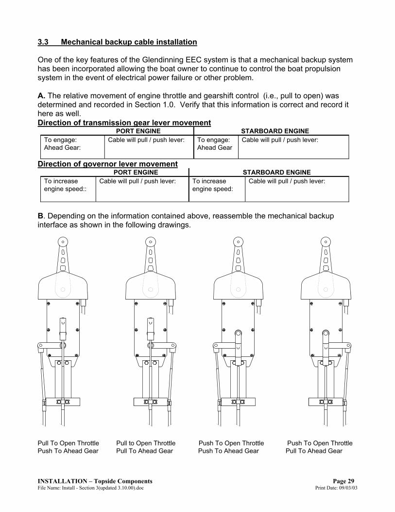
3.3 Mechanical backup cable installation One of the key features of the Glendinning EEC system is that a mechanical backup system has been incorporated allowing the boat owner to continue to control the boat propulsion system in the event of electrical power failure or other problem. A. The relative movement of engine throttle and gearshift control (i.e., pull to open) was determined and recorded in Section 1.0. Verify that this information is correct and record it here as well. Direction of transmission gear lever movement
PORT ENGINE STARBOARD ENGINE To engage: Cable will pull / push lever: To engage: Cable will pull / push lever: Ahead Gear: Ahead Gear
Direction of governor lever movement PORT ENGINE STARBOARD ENGINE To increase engine speed::
Cable will pull / push lever: To increase engine speed:
Cable will pull / push lever:
B. Depending on the information contained above, reassemble the mechanical backup interface as shown in the following drawings.
Pull To Open Throttle Pull to Open Throttle Push To Open Throttle Push To Open Throttle Push To Ahead Gear Pull To Ahead Gear Push To Ahead Gear Pull To Ahead Gear

Page 30 INSTALLATION – Topside Components Print Date: 09/03/03 File Name: Install - Section 3(updated 3.10.00).doc
NOTE Be sure to connect the mechanical backup linkage exactly as directed in the preceeding drawings, using the electrical connection cable as a reference. Although it may seem that these connections are “backwards” from normal convention (i.e., on the left hand drawing throttle is set for “pull to open” although it would appear to be “push to open”), this arrangement is necessary due to parallel connection of cables at Actuator coupler plates. C. Mount the throttle and gear control cables to the mechanical backup interface as shown above. Use the middle set of holes provided at the bottom of the mechanical backup assembly for mounting the control cable clamps. Verify that the slot on the end fitting of the control cable is mated correctly to the control cable clamp. D. Screw the terminal eyes on the end of each control cable, ensuring that the terminal eye has 1/2” of thread engagement. Attach the terminal eyes to the mechanical backup interface control levers using the shoulder screws provided. Use grease on the shoulder of the screws to make the mechanical backup easier to move. E. Route the control cables to each actuator in the engine room. Take note on port and starboard and which side of the actuator is the gear side and which side is the throttle side. F. Mount the control cable to the actuator as shown in the drawing on section 2.2 page 3. Use the middle set of holes provided. G. Screw the cable end spring mechanism onto the end of the control cable, obtaining at least 1/4” of thread engagement (7 turns). H. Adjust the gear control backup cable as follows:
1) Verify the following: - transmission control lever is in the Neutral detent. - mechanical backup control head is in the Neutral detent. 2) Compare the relative position of the top coupler plate with the position of the middle and bottom plate. They should all line up at neutral. If not adjust the hex nut. 3) If hex nut does not have at least ¼” of thread engagement then remount cable in the other set of mounting holes.
I. Attach the throttle control backup cable as follows:
1) Verify the following: - governor or throttle is at idle for pull to open and at full open for push to open. - mechanical backup control head is in the Neutral detent. 2) Compare the relative position of the top coupler plate with the position of the middle and bottom plate. They should all line up at idle or full open.
3) If hex nut does not have at least ¼” of thread engagement then remount cable in the other set of mounting holes.

INSTALLATION – Topside Components Page 31 File Name: Install - Section 3(updated 3.10.00).doc Print Date: 09/03/03
J. After installation of the mechanical backup cables is completed, verify the following on both engines: - With the Control head at Neutral Detent, the transmission control lever is at the Neutral detent position. - Move the Control head to the Ahead Idle detent, the transmission control lever should move in the appropriate direction (toward ahead). The engine governor should be at the idle (mechanical stop) position.
NOTE It may be easier to do the preceeding steps (paragraphs F – J, mechanical backup cable connection to the Actuator coupler plates) at the conclusion of system calibration rather than at this point of the installation. If so, it may be necessary to “tie-wrap” all three coupler plates in alignment so that the coupler pins will retract smoothly during the Calibration process. 3.4 Station Processor Installation A. The Station Processor should be mounted in the area below the control handle. The location chosen for the Station Processor should be relatively dry, preferably on the overhead or bulkhead of the compartment. A 6 foot connection cable is provided with each control handle for connection to the station processor and the station processor should be located within this distance from the control head. B. The station processor should be mounted using #10 (5 mm diameter) machine bolts or screws. If using screws, screw length should be no less than 1 ½” (40mm). If using machine bolts, lockwashers / locknuts must be used. C. After mounting the Station Processor, connect the Control Head cable plug to the large connector on the Station processor. Make sure the pins are properly lined up when installing. Once the connector is fully engaged, thread the connector nut clockwise until it is tight.
NOTE DO NOT FORCE CONNECTOR INTO RECEPTACLE - BE CERTAIN THAT THE CONNECTOR IS PROPERLY ALIGNED PRIOR TO PLUGGING IT IN! If the connector is properly aligned with its receptacle, only a small amount of physical force will be necessary to insert connector into Engine Processor. Failure to properly align the connector may damage it and cause the EEC system to fail. 3.5 Station Processor to Engine Processor Connection cables
Page 32 INSTALLATION – Topside Components Print Date: 09/03/03 File Name: Install - Section 3(updated 3.10.00).doc
Each Station Processor is connected to the Engine Processor using pre-terminated connection cables. These wires are available in lengths of 10 to 100 feet in 10’ increments and have pre-terminated ends for connection to the Station and Engine Processors. A. Route the cables between the Engine and Station Processor. The cables should be free of bends or kinks in the wire. The Metal Connector on the SP / EP Connection Cable is connected to the Station Processor and the plastic connector is connected to the receptacle in the Engine Processor. B. Connect the metal connector to the smaller connector plug on the Station Processor. Once the connector is fully engaged, tighten the connector nut. Make sure the pins line up when installing.
NOTE DO NOT FORCE CONNECTOR INTO RECEPTACLE - BE CERTAIN THAT THE CONNECTOR IS PROPERLY ALIGNED PRIOR TO PLUGGING IT IN! If the connector is properly aligned with its receptacle, only a small amount of physical force will be necessary to insert connector into Engine Processor. Failure to properly align the connector may damage it and cause the EEC system to fail. C. Connect the other end of the Connection cable to one of the station connections on the Engine Processor (S1 - S6). The “main station”, which is the control station normally equipped with the EEC system power switch and mechanical backup, should be connected to the S1 position at the EP. All other stations should be connected to Engine Processor in ascending order (S2, S3, S4, S5, S6). (Do not skip stations! – the Engine Processor will not “look” for a station connected to a higher station connection point once it detects an empty connection receptacle). Once the cable connector is fully engaged in its plug, rotate the connector nut clockwise until a “detent” is felt. This will lock the connector in place. Make sure to line up the pins before inserting into the connector.
NOTE DO NOT FORCE CONNECTOR INTO RECEPTACLE - BE CERTAIN THAT THE CONNECTOR IS PROPERLY ALIGNED PRIOR TO PLUGGING IT IN! If the connector is properly aligned with its receptacle, only a small amount of physical force will be necessary to insert connector into Engine Processor. Failure to properly align the connector may damage it and cause the EEC system to fail. D. Mount the SP connection cables in smaller slots on the EP. Use the installed tie wrap holders to provide proper strain relief to the connection cables. Fill up the extra slots with the plugs provided.

SYSTEM CALIBRATION Page 33 File Name: Install - Section 4 (calib).doc Print Date: 9/3/2003
4.0 SYSTEM CALIBRATION Introduction The purpose of EEC system calibration is to adjust the EEC system actuator movement (length of travel) so that it matches the movement of the engine governor lever, transmission gear selector lever, and / or trolling valve control lever. The EEC system must be calibrated after the system is installed, prior to initial operation. In addition, the EEC system must be re-calibrated whenever any change is made in the control levers of the engine governor, reduction gear, or trolling valve. Re-calibration will be also be required if any changes are made to the push-pull control cables that connect each actuator to the engine governor and / or gear box.
NOTE Failure to recalibrate the EEC system after changes are made to engine and / or reduction gear control levers, or the interconnecting push-pull cables, could cause failure of one or more system components.
Calibration Procedure Overview Calibration of the Electronic Engine Control system consists of manually controlling each actuator through the complete range of travel of the associated engine or gear control lever . At each endpoint of travel - engine throttle idle position, engine throttle full speed position, ahead gear position, astern gear position, etc. - the EEC system will “memorize” the location of this position and will use this position as a reference during operation. For example, during normal operation, when the vessel operator moves the control head lever to the "idle, neutral" position, the EEC system will move the engine throttle and gear control levers to the idle engine speed postion and neutral gear position that were set during the calibration procedure. Obviously, if this position is not correctly set during calibration, the EEC system will not be able to move the control levers to the correct position. Manual calibration consists of 6 steps: 4.1 System preparation 4.4 Handle calibration
4.2 Entering Calibration Mode 4.5 Exiting Calibration Mode
4.3 Actuator positioning 4.6 Calibration verification
4.1 System Preparation Prior to beginning manual calibration, the EEC system must be prepared as follows:
1) Before calibration, all connecting push-pull control cables between the EEC actuators and engine, transmission, and trolling valve must be completely installed. Once calibration is completed, any changes that are made to the
WARNING Failure to properly calibrate the system prior to initial operation may cause significant damage to the system.

Page 34 SYSTEM CALIBRATION Print Date: 9/3/2003 File Name: Install - Section 4 (calib).doc
control cables or the engine / transmission control levers will make re-calibration of the EEC system necessary.
NOTE Although the mechanical backup control cables may be hooked up (the cables which connect the EEC actuators to the mechanical backup control head), it may be easier to go through the calibration process with these cables disconnected at the actuator. These control cables can be safely hooked up after the calibration process is completed.
2) Verify that the Main station control handles are in the neutral position. The Main
Station is the control station that is connected to the "S1" connection in the Engine Processor. Normally, the Main station is also equipped with the mechanical backup cables.
3) Turn OFF all power to the EEC system. 4) Open the Engine Processor (EP) access plate to expose the DIP Switches and
LED indicator light assembly.
5) Set the switches as per the chart that follows.
Switch Bank 1 Switch Bank 2 Switch 1
PORT Gear Cable Direction ON – Pull to ahead OFF – Push to ahead
Switch 2
STBD Gear Cable Direction ON – Pull to ahead OFF – Push to ahead
Number of Stations 1 Station - Switch 1 – ON 2 Stations - Switch 1 – OFF Switch 2 – OFF Switch 2 – ON Switch 3 – OFF Switch 3 – OFF
3 Stations – Switch 1 – ON 4 Stations – Switch 1 – OFF Switch 2 – ON Switch 2 – OFF Switch 3 – OFF Switch 3 – ON
5 Stations – Switch 1 – ON 6 Stations – Switch 1 – OFF Switch 2 – OFF Switch 2 – ON Switch 3 – ON Switch 3 – ON
Switch 3
Throttle Act. Cable Direction (Both engines) ON – Pull to open OFF – Push to open
Switch 4
Port Troll Lockup Direction ON – Pull to Full Lockup OFF – Push to Full Lockup
Calibration ON – Calibration ON OFF – Calibration OFF (Run Mode)
Switch 5
STBD Troll Lockup Direction ON – Pull to Full Lockup OFF – Push to Full Lockup
Calibration type ON – Manual Calibration (Leave switch ON)
Switch 6
Automatic Synchronizer ON – Enabled OFF – Disabled
Switch 7
Troll valve Operation ON – Enabled OFF – Disabled
Switch 8
Troll valve Mode ON – Throttle at Top end OFF – Troll only (no throttle)
Troubleshoot Mode ON – Enable (leave switch OFF) OFF – Disable

SYSTEM CALIBRATION Page 35 File Name: Install - Section 4 (calib).doc Print Date: 9/3/2003
NOTE: To set the switch position, push down on the side of the switch that is marked with your desired setting. Example, Push down on the OFF side if you want the switch to be in the OFF position. The following provides more detail regarding the above switch settings: Switch Bank 1
Switch 1, 2 - This switch position is determined by the direction of the control cable connection at the transmission gear control lever. For example, "Pull to ahead" indicates that the control cable pulls on the control lever to place the transmission in the ahead direction. This switch position should correspond with the data obtained in Section 1.1 of the manual.
Switch 3 - This switch position is determined by the direction of the control cable connection at the engine governor / throttle. For example, "Pull to open" indicates that the control cable pulls on the governor to increase engine RPM ("open" the engine). This switch position should correspond with the data obtained in Section 1.2 of the manual.
Switch 4,5 - This switch position is determined by the direction of the control cable connection at the troll valve control lever (if installed). For example, "Pull to Full Lockup" indicates that the control cable pulls on the troll valve control lever to close the troll valve and place the transmission in the no slip position. This switch position should correspond with the data obtained in Section 1.3 of the manual. (If a troll valve is not installed, the position of these switches does not matter).
Switch 6 - This switch position enables the Automatic Synchronizer capability. This switch should normally be turned ON in order to enable the capability for Automatic Synchronization during system operation. For engines with electronic governors where this capability is handled by the engine system (i.e., Caterpillar 3176, 3406, 3412, etc), this switch should be in the OFF position during calibration.
Figure 5.2 Close up view of Switch setting positions in Engine
Engine Processor
“LO” EpromSerial Number
“HI” EpromSerial Number
These two lights are constantly litwhen EEC system is in operation.
Top
Bottom
LED Display8 7 6 5 4 3 2 1
SwitchBank 1
SwitchBank 2
Switch inON position
Switch inOFF position

Page 36 SYSTEM CALIBRATION Print Date: 9/3/2003 File Name: Install - Section 4 (calib).doc
L8 L7 L6 L5 L4 L3 L2 L1 ONON
Switch 7 - This switch position enables the capability for Trolling Valve operation. - Turn switch ON if troll valve actuators are installed. - Turn switch OFF if troll valve actuators are not installed.
Switch 8 - This switch position determines the type of Trolling Valve operation. - Turn switch ON if combined troll valve and throttle operation is desired. (In Troll
Mode, initial 65% of handle movement will control troll valve from full slip to lockup, final 35% of handle movement will control throttle from idle to approximately 40% RPM. )
- Turn switch OFF if combined troll valve and throttle operation is not desired. (In Troll Mode, handle will only control troll valve; engine throttle will remain at idle.)
NOTE: This switch position (Switch #8) is only applicable for Engine Control systems equipped with Version 5 software or later. Leave switch OFF while calibrating system for earlier software versions.
Switch Bank 2
Switch 1, 2, 3 - These switches should be set for the number of stations which will be connected to the Engine Processor.
Switch 4 - Turn this switch ON to enable the Calibration Mode. After Calibration is completed, turn switch OFF. (See Section 4.5)
Switch 8 - This switch enables "Troubleshoot" Mode, which is used to diagnose EEC system problems. This switch must be turned OFF during calibration.
NOTE: Switches 5, 6, and 7 in Switch Bank 2 should be placed in the OFF position during calibration
4.2 Entering Calibration Mode 1. Set DIP switches as described in the chart in the above section
The EEC system will be programmed to operate based on the positions of the DIP Switches as they are set at the start of calibration. It is very important that care be taken to position the DIP switches correctly prior to turning the system “ON” in calibration mode. As a minimum the following switch must be set to "ON" to enter the Calibration Mode: DIP Switch Bank 2, Switch 4
2. Remove the Manual Calibration Box (MCB) from the EP enclosure. 3. Turn the EP “ON”. The system will go through its startup sequence
and the actuator solenoids will be energized locking the actuator coupler pins down. The LED’s on the Engine Processor will then change to the sequence indicated at the right.

SYSTEM CALIBRATION Page 37 File Name: Install - Section 4 (calib).doc Print Date: 9/3/2003
L8 L7 L6 L5 L4 L3 L2 L1 ONON
NOTE If the coupler plates on each Actuator are not lined up (these are the plates which are connected to the push-pull control cables), the system will not be able to enter the calibration mode. If the coupler plates are not lined up, the system will try for three times to start up and then will go in to alarm mode. If this happens, turn the system “OFF”, line up the actuator coupler plates, and then turn the system “ON” again. In some cases, the actuator coupler plates may be kept in line by connecting all three coupler plates together with a electrical wire tie ('tie wrap'). This may be likely to happen if the mechanical backup control cables are not hooked up as recommended in Section 4.1. 4. The actual calibration procedure can be started by pressing the
“Accept” button one time on the Manual Calibration Box (MCB). The EP LED lights will change to the sequence indicated at the right .
This light sequence indicates that the system is now ready to begin to calibrate the Actuator "end-point" positions. Calibration will begin with the Starboard throttle actuator. 4.3 Actuator Positioning The actuators are calibrated by moving each actuator to each endpoint position and then “memorizing” that position by pressing the MCB “Accept” button. For a typical twin engine boat without trolling valves, there will be eight positions to identify: 1) Starboard throttle idle 5) Port throttle idle 2) Starboard throttle full throttle 6) Port throttle full throttle 3) Starboard gear ahead 7) Port gear ahead 4) Starboard gear astern 8) Port gear astern For a boat that is equipped with a trolling valve, there will be a total of twelve positions to identify, the eight positions listed above as well as the following additional positions:
9) Starboard troll valve closed (lockup) 10) Starboard troll valve open 11) Port troll valve closed (lockup) 12) Port troll valve open
Each actuator is calibrated by the following procedure: 1) Move the actuator by depressing the extend or retract button to move the actuator toward the endpoint of travel of it’s associated control lever. The actuator will move steadily if the button is held down. The actuator will only move a small amount if the button is quickly pressed and released.
NOTE 1. The actuators that are calibrated must be done in a specific order: • Starboard throttle • Starboard gear • Port throttle • Port gear • Starboard troll valve • Port troll valve 2. The order of the actuator endpoint that is calibrated is not important; that is, full throttle may be calibrated before or after idle, astern gear calibrated before or after the ahead gear position.

Page 38 SYSTEM CALIBRATION Print Date: 9/3/2003 File Name: Install - Section 4 (calib).doc
2) The actuator should be moved to a position where the associated engine / reduction gear control lever has reached its mechanical stop position. This can be done by observing the push-pull cable connection to the control lever and stopping the actuator when the connection visibly tightens. Move the actuator in the opposite direction if the connection appears excessively tight. Make sure that the cable is not binding. It is important to find the proper balance between the control cable position being "too loose" and not reaching its endpoint position (and therefore the engine not achieving idle speed or full throttle), and the cable being set up "too tight" and constantly operating in a compressed or stretched condition when moving to its endpoint of travel. Continue adjusting the actuator position until a good position has been achieved. 3) When the control lever endpoint is properly achieved, the position can be “memorized” by pressing the MCB “Accept” button (1 time). 4) Move the actuator in the opposite direction to calibrate the other endpoint of the control lever. Again, observe the push-pull cable connection and move the actuator to the point where the lever is hard against its mechanical stop, but not binding. 5) When the control lever endpoint is properly achieved, the position should be “memorized” by pressing the MCB “Accept” button. 6) After both endpoints have been calibrated, press the “Accept” button one additional time to calibrate the next actuator calibration position - see the order of calibration specified above. 7) Once both endpoints of the final actuator have been "memorized" - either the port gear actuator or the port troll valve actuator - the "Accept" button must be pressed one additional time. After the Accept button is pressed, the actuators will then move to the "idle / neutral" position (i.e., the gear actuators will move to neutral, the throttle actuators will move to idle) to confirm that the actuator positioning portion of calibration is complete. This will confirm that all Actuators have been successfully calibrated, all of the endpoint positions (engine idle, engine full throttle, etc.) have been stored in memory, and you are now ready to move the Handle Calibration.
NOTE It is important to note that the Actuators will move to the "idle / neutral" position when calibration is complete. If the Actuators do not move, it is possible that an error has been made during the calibration process: - The "Accept" button was not pressed one additional time, as described in Paragraph 7 above. - Troll Valve Operation is set (DIP Switch Bank #1, Switch 7 in ON), but no Troll Valve actuators are installed.

SYSTEM CALIBRATION Page 39 File Name: Install - Section 4 (calib).doc Print Date: 9/3/2003
L8 L7 L6 L5 L4 L3 L2 L1 ON
ON
LED Light Sequence As an aid to the technician, the LEDs located in the EP access port will light up indicating the specific Actuator that is currently being calibrated, and whether both endpoints have been calibrated. The LEDs will light up according to the following sequence:
After system startup / prior to beginning calibration Starboard throttle calibration Starboard Gear calibration Port throttle calibration Port Gear calibration Starboard Troll Valve calibration
(if boat is equipped with troll valves) NOTE: If boat is not equipped with troll valves, this light indication will signal calibration complete Port Troll Valve calibration
(if boat is equipped with troll valves)
LED L1 and L8 are ON (The rightmost (2) LEDs are always on when EEC system is operational).
LED L2 is ON
L8 L7 L6 L5 L4 L3 L2 L1 ONON
LED L2 and L3 is ON
L8 L7 L6 L5 L4 L3 L2 L1 ONON
L8 L7 L6 L5 L4 L3 L2 L1 ONON
LED L2, L3 and L4 is ON
L8 L7 L6 L5 L4 L3 L2 L1 ONON
LED L2, L3, L4, and L5 is ON
L8 L7 L6 L5 L4 L3 L2 L1 ONON
LED L2, L3, L4, L5 and L6 is ON
L8 L7 L6 L5 L4 L3 L2 L1 ONON
LED L2, L3, L4, L5, L6 and L7 is ON

Page 40 SYSTEM CALIBRATION Print Date: 9/3/2003 File Name: Install - Section 4 (calib).doc
Actuator calibration complete
(If troll valve actuators are installed)
Calibration Notes
1) The above sequence of events should be carefully followed anytime that the EEC system is being installed or if several of the Actuator positions must be re-calibrated (such as after an engine replacement). If only one Actuator position must be re-calibrated - for example, if the idle or full speed setting of one engine must be changed - it is not necessary to recalibrate every Actuator position. In this case, you can skip the calibration of Actuator positions that are already set and are satisfactory by simply pressing the "Accept" button instead of the "Extend" or "Retract" buttons. If the "Accept" button is the first button pressed, the Calibration process will skip that particular Actuator. You can identify which Actuator is in the process of being calibrated by looking at the LED indicators shown in the previous diagrams. 2) During the calibration process, two of the Control Station indicating lights will be illuminated (outer left and outer right). This is normal - see next section on Handle Validation. 4.4 Handle Validation The purpose of the Handle Validation procedure is to permit the installer and / or repair technician to verify that each control handle, control button, and indicating light correctly operation at the conclusion of the installation. The Handle Validation procedure does not actually calibrate the handles - this is done each time that the EEC system is turned on in normal operation. Handle Validation can be done upon the completion of Actuator Postioning (Paragraph 4.3). You can confirm that you are ready for Handle Validation if the Actuators have moved to the "neutral / idle" position as described previously in Paragraph 4.3, item 7.
NOTE Handle Validation does not have to be done each time you are calibrating the system. If you just calibrated the actuators a second time (i.e. the actuator settings were not correct and you had to re-calibrate) you can ignore the Handle Validation process and go to Exiting Calibration Mode (paragraph 4.5).
L8 L7 L6 L5 L4 L3 L2 L1 ONON
All LED's are ON

SYSTEM CALIBRATION Page 41 File Name: Install - Section 4 (calib).doc Print Date: 9/3/2003
To begin handle calibration, go to the Main Control station (the control station that is connected to the "S1" connection in the Engine Processor).
1) During the Actuator Position process, the outer left and outer right indicating lights are illuminated (these are normally described as the "TAKE" and "SLOW" lights). When the calibration process is complete, the inner left and inner right ("SYNC" and "WARM") lights will be on. (If the outer lights are still on, this would indicate that the Actuator Process has not yet been completed - see paragraph 4.3, item 7.
2) Move the port (left) control lever to "full ahead" position. The TAKE indicator light will go on.
3) Move the port (left) control lever to "full reverse" position. The SYNC indicator light will go on. (The TAKE indicator light will remain on.)
4) Move the port (left) control lever to the neutral position. 5) Move the starboard (right) control lever to "full ahead" position. The WARM
indicator light will be lit. (The TAKE and SYNC indicator lights will remain on.) 6) Move the starboard (right) control lever to "full reverse" position. The SLOW
indicator light will be lit. (The TAKE, SYNC, and WARM indicator lights will remain on.)
7) Move the starboard (right) control lever to the neutral position. 8) Turn Off each of the indicator lights by pressing each of the buttons starting
from left to right (TAKE, SYNC, WARM, SLOW) 9) Immediately after the SLOW light has been turned off, all (4) lights will blink
together 1 time to indicate that the Handle Validation procedure has been completed for this station.
The proper operation of all Main Station components - control lever sensors, indicating lights, and control buttons - has now been confirmed. Check each of the other control stations by following a similar procedure to that described above: 1) Each of the other Control Stations will have the outer left and outer right indicating lights illuminated. In order to perpare the station for Handle Validation, press the TAKE button one or two times - the inner left and right lights will be illuminated. 2) Move the control levers as described in steps (2) - (7) above. 3) Turn Off each of the indicator lights by pressing each of the buttons starting from left to right (TAKE, SYNC, WARM, SLOW) When the final station has been tested, all of the indicator lights will “blink“. This indicates that the handle calibration procedure has been satisfactorily completed. 4.5 Exiting Calibration Mode After all the actuators are calibrated, restore the EEC system to normal operation by the following steps: 1) Turn “OFF” the EEC system.
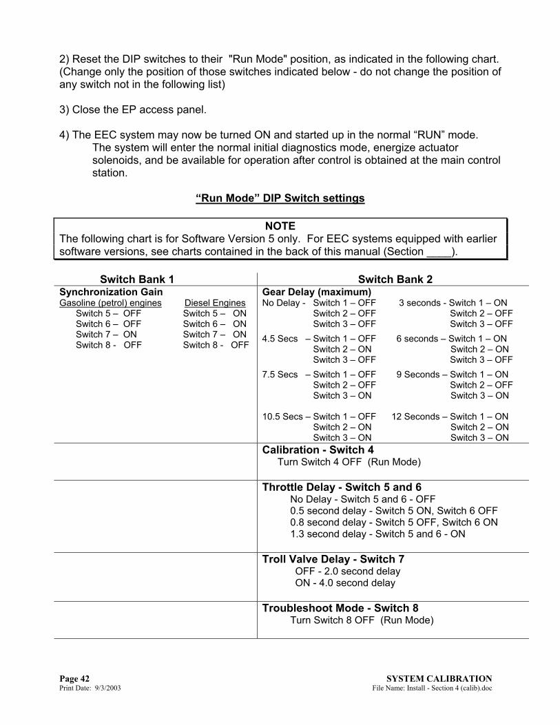
Page 42 SYSTEM CALIBRATION Print Date: 9/3/2003 File Name: Install - Section 4 (calib).doc
2) Reset the DIP switches to their "Run Mode" position, as indicated in the following chart. (Change only the position of those switches indicated below - do not change the position of any switch not in the following list) 3) Close the EP access panel. 4) The EEC system may now be turned ON and started up in the normal “RUN” mode.
The system will enter the normal initial diagnostics mode, energize actuator solenoids, and be available for operation after control is obtained at the main control station.
“Run Mode” DIP Switch settings
NOTE
The following chart is for Software Version 5 only. For EEC systems equipped with earlier software versions, see charts contained in the back of this manual (Section ____).
Switch Bank 1 Switch Bank 2 Synchronization Gain Gasoline (petrol) engines Diesel Engines Switch 5 – OFF Switch 5 – ON Switch 6 – OFF Switch 6 – ON Switch 7 – ON Switch 7 – ON Switch 8 - OFF Switch 8 - OFF
Gear Delay (maximum) No Delay - Switch 1 – OFF 3 seconds - Switch 1 – ON Switch 2 – OFF Switch 2 – OFF Switch 3 – OFF Switch 3 – OFF
4.5 Secs – Switch 1 – OFF 6 seconds – Switch 1 – ON Switch 2 – ON Switch 2 – ON Switch 3 – OFF Switch 3 – OFF
7.5 Secs – Switch 1 – OFF 9 Seconds – Switch 1 – ON Switch 2 – OFF Switch 2 – OFF Switch 3 – ON Switch 3 – ON 10.5 Secs – Switch 1 – OFF 12 Seconds – Switch 1 – ON Switch 2 – ON Switch 2 – ON Switch 3 – ON Switch 3 – ON
Calibration - Switch 4 Turn Switch 4 OFF (Run Mode)
Throttle Delay - Switch 5 and 6 No Delay - Switch 5 and 6 - OFF 0.5 second delay - Switch 5 ON, Switch 6 OFF 0.8 second delay - Switch 5 OFF, Switch 6 ON 1.3 second delay - Switch 5 and 6 - ON
Troll Valve Delay - Switch 7 OFF - 2.0 second delay ON - 4.0 second delay
Troubleshoot Mode - Switch 8 Turn Switch 8 OFF (Run Mode)

SYSTEM CALIBRATION Page 43 File Name: Install - Section 4 (calib).doc Print Date: 9/3/2003
Switch Bank 1 Switch 5,6,7,8 - Synchronization gain adjusts the rate at which the EEC system in
adjusts the speed of the port engine speed during automatic synchronization. Depending on a number of variables (type of engine, size of boat, shape of hull, etc.), this response rate will vary from boat to boat. The settings that are given are good settings to start with for sea trials. After testing, it may be necessary to adjust the Synchronization Gain for a faster or slower response.
NOTE: Switches 1,2,3, and 4 in Switch Bank 1 can be in any position (ON or OFF) during Run Mode. However, it is best if they are left in the same position as they are set during Calibration. (This will make re-calibration easier to do, if it is laster found necessary to do).
Switch Bank 2 Switch 1, 2, 3 - These switches adjust the maximum amount of Gear Delay, which is a
time delay introduced by the EEC system when going from Ahead or Reverse (with throttle) to Neutral. When Gear Delay is selected, and the Control Head handle is moved from the "in-gear" position (with engine throttle above approximately 1000 RPM) to the Neutral position, the Throttle Actuator will move the engine governor to idle and then the Engine Processor will wait for the selected period of time before moving the Gear from Ahead to Neutral. (See the Operations Manual for more information on this delay).
Switch 4 - Turn this switch OFF to enable the Run Mode. Switch 5 and 6 - These switches adjust the amount of Throttle Delay, which is a time
delay introduced by the EEC system when moving the Control Head from Neutral to Ahead or Reverse gear. When Throttle Delay is selected, and the Control Head handle is moved from the Neutral position to either Ahead or Reverse, the Gear Actuator will move the transmission control lever to it's appropriate "in-gear" position and then Engine Processor will wait for the selected period of time before allowing the Throttle Actuator to increase engine RPM. (See the Operations Manual for more information on this delay).
Switch 7 - Troll Valve Delay. When the "Throttle at Top end of Troll" mode is selected during Calibration (see Section 4.1, Switch Bank 1, Switch 8 = "ON"), a delay is always introduced when moving the Control Head from the throttle range back into the troll valve range, prior to the troll valve opening. This will ensure that the engine speed is below the maximum RPM permitted for troll valve operation when the troll valve is opened.
Switch 8 - This switch enables "Troubleshoot" Mode, which is used to diagnose EEC system problems. This switch must be turned OFF during Run Mode.
Page 44 SYSTEM CALIBRATION Print Date: 9/3/2003 File Name: Install - Section 4 (calib).doc
4.6 Calibration Verification Upon completion of the Calibration procedure, it is advisable that the operation of the EEC system be inspected to verify that each engine throttle and transmission lever is being properly moved in the correct direction and through the full range of travel.
A suggested verification procedure follows: 1. Take control at any station that is convenient for good communication between the engine room and helm station. 2. With the station control levers (port and starboard) in the neutral position, verify the following for both engines and transmissions: Engine governor - Idle position (mechanical stop) Gear control lever - Neutral position
Trolling valve - Lockup position (troll valve closed) (if installed) 3. Move the station control levers (port and starboard) to the ahead detent position. Verify that both gear control levers have moved to the ahead position and that the control cable is not binding. 4. Move the station control lever (port and starboard) to the astern detent position. Verify that both transmission levers have moved to the astern position and that the control cable is not binding. 5. Move the station control lever (port and starboard) to the full astern position. Verify that both engine governors are at the full throttle (mechanical stop) position and that the control cable is not binding 6. Move the station control lever (port and starboard) to the neutral position. Verify that both engine governors are at the idle (mechanical stop) position and that the control cable is not binding.
NOTE It is extremely important that the Calibration be verified after the Calibration Procedure is completed. Failure to do this can cause gear / transmission failure if the gear control lever is not moved into it's correct position.

SYSTEM CALIBRATION Page 45 File Name: Install - Section 4 (calib).doc Print Date: 9/3/2003
7. (Troll valve equipped boats only) - Move the station control lever (port and starboard) to the neutral position. Press and release the troll switch on the control. Troll switch light will illuminate indicating that troll mode is energized. Verify that both troll actuators have moved to troll valve open position and that the control cable is not binding. 8. (Troll valve equipped boats only) - Move the station control lever (port and starboard) to the full throttle position. Verify that both troll actuators have moved toward lockup position, but have not moved into the detented lock-up position and that the control cable is not binding. 9. (Troll valve equipped boats only) - Move the station control lever (port and starboard) to the neutral position. Press and release the troll switch on the control. Troll switch light will go out indicating that troll mode is off and that normal gear / throttle operation is available.. Verify that both troll actuators have returned to the lockup position and that the control cable is not binding. After performing the Calibration Verification check, if you find that one actuator position needs to be changed, go to back to the beginning of the Calibration section and follow the instructions. You can skip over actuator positions just by pressing the “Accept” button. When skipping, watch the LED’s. This will let you know which actuator position you are at. This completes the calibration procedure. The electronic engine control system is now fully operational and ready for use.
NOTE The following points should be kept in mind when verifying actuator position and operation: Direction of travel - The location of engine idle and full throttle, gear ahead and astern, and troll valve lockup / slip should be considered to ensure that the EEC actuator is moving the engine and gear controls in the appropriate direction. Actuator endpoint - The actuator should move its associated control lever to the mechanical stop without placing undue strain on the control cable or control lever. Control lever detent position - When position the gear lever or trolling valve lever, it may be helpful to disconnect the push-pull cable from the lever and move the control lever independently from the EEC system.

Page 46 SYSTEM CHECKLIST Print Date: 9/3/2003 File Name: Install - Section 5 (Checklist).doc
ELECTRONIC ENGINE CONTROL System Inspection / Checkout
General Overview System Inspection / Checkout consists of 2 steps:
a) Component Installation Checks – verify that the components appear to be correctly mounted and installed.
b) Operational Tests. Component Installation Checks 1. Engine Processor (Internal) 1.1 Before closing DIP Switch Access cover, verify that DIPswitches are correctly set for:
- Correct synchronizer gain setting (Bank 1, Switches 5-8) - Selected gear delay (Bank 2, Switches 1-3) - Selected throttle delay (Bank 2, Switches 5 – 6) - EP is in Run mode (Bank 2, Switch 4 and Switch 8 = OFF)
After switch settings are verified to be correct, close DIP Switch Access cover and tighten (4) wing nuts
1.2 Inside wire connection “cavity”, verify that all actuator power wires are properly connected to correct barrier strip terminal – verify jacket insulation color - and are tight. Verify that actuator feedback plugs are fully inserted and plug nuts are securely tightened (fully clockwise).
1.3 Verify that all connection wires bushings are fitted into correct groove in Engine Processor. All wires should be secured with tie-wraps.
1.4 Close Engine Processor cover.
2. Engine Processor (External) 2.1 Verify Engine Processor is securely fastened to boat structure
2.2
Verify electrical power connections: Battery negatives – Negatives from both batteries should be connected (not at Engine
Processor. It is vital that there be zero voltage potential between battery negative terminals. Battery negative terminals should be connected to Bonding system also.
Negative lead – Negative wire from EEC system is connected to single battery negative. Positive leads – Power should be connected from Battery positive terminal or Disconnect
switch (battery side of switch) to EP via 25 Amp fuse / circuit breaker. Check that all battery connections are tight.
2.4 Inspect connection of tach sender input wire (if installed). Verify that tach wires for Port and Stbd engines are connected to appropriate terminal. Inspect installation of mechanical drive adapter (if installed)
2.5 Bonding wire should be connected between Engine Processor and Engine Room bonding
system. Verify that Battery negative is also connected to Engine Room bonding system.

SYSTEM CHECKLIST Page 47 File Name: Install - Section 5 (Checklist).doc Print Date: 9/3/2003
3. Actuators 3.1 Verify Actuators are securely fastened to boat structure
3.2
Verify tightness of terminal eye bolts, cable clamps, control cable jam nuts
3.3 Verify that terminal eyes have at least 1/4” thread engagement (at least 6 threads)
3.4 Verify that start interlock wiring is connected to correct engine.
4. Control Heads 4.1 Verify that all control heads are securely fastened to boat structure
4.2
(Mechanical backup control head) Verify tightness of: terminal eye bolts, cable clamps, control cable jam nuts
4.3 Verify that terminal eyes have at least 1/4” thread engagement (at least 6 threads)
5. Station Processor 5.1 Verify that SP / EP cable and Control Head cable metal plug nuts are securely tightened
(fully clockwise).

Page 48 SYSTEM CHECKLIST Print Date: 9/3/2003 File Name: Install - Section 5 (Checklist).doc
Operational Checks 6.1 Prior to startup, verify that system has been calibrated. (System must be calibrated prior
to running)
6.2
If system has been calibrated, do the following: - Verify EEC power switch at main helm station is OFF - Turn ON Engine Room circuit breakers to EEC system. - Power up EEC system as per normal procedure.
6.3 Perform calibration verification: a) Move both Control Head handles into Ahead idle detent. Verify that both gear
levers (at gearbox) move to end of travel, but are not binding against end stops. Verify that engine throttle levers are at idle position.
b) Move both Control Head handles to Full Throttle. Verify that both engine throttle levers move to end of travel, but are not binding against end stops
c) Move both Control Head handles to Astern idle detent. Verify that both gear levers (at gearbox) move to end of travel, but are not binding against end stops. Verify that engine throttle levers are at idle position.
d) Move both Control head handles to Neutral detent. Verify that both gear levers are in the neutral detent position.
6.4 Verify the following at each control station
Normal run mode (Full Ahead – Full Astern – Full Ahead) Warm up mode Slow Mode
6.5 Move Starboard Control Handle out of neutral position. Attempt to start engine. - Engine should not start; if it does, start interlock has not been hooked up correctly. - Move starboard control handle back to neutral position
Perform same check for port engine.

ELECTRONIC ENGINE CONTROL System Inspection / Checkout
The Electronic Engine Control is a relatively complex system that has components located throughout the boat. Although efforts have been made to make the system reasonably easy to install, it is vital that the control system be thoroughly checked out prior to initial operation in order to verify that the system has been correctly installed and to make final adjustments to the system components. Due to the system complexity, it is very important that system checkout be done carefully and methodically. The following procedure and checklist is provided as a guide for this inspection. Overview In general, the system inspection and startup procedure involves the following four (4) steps:
1. Component Installation Verification This is done before calibration of the EEC system, verifying that each EEC system component has been installed correctly.
2. Calibration (Section 5.0) Prior to initial operation of the EEC system, it is necessary to calibrate the length of travel for each actuator to match the actual conditions. See Installation Manual, Section 5.0 for instructions on EEC system calibration.
3. Mechanical backup final hookup (Section 3.3, paragraph H - J) It is recommended that the final hookup of the mechanical backup cables to each actuator not be completed until after the system has been electronically calibrated. See Installation Manual Section 3.3, paragraph H – J for instructions on how to connect and adjust the mechanical backup cables at the gear and throttle actuators. (Per the Installation Manual Section 3.3, paragraph B, the mechanical backup cables should be connected below the mechanical backup control head.)
4. Sea Trial preparation checks Prior to the initial operation of the EEC system underway, some final checks and adjustments should be made to ensure that the system is ready for operation.
5. Sea Trial Operational checks
During sea trials, the engine control system should be methodically tested, using the procedure
By carefully doing the above tests and adjustments in the exact order described above, the installer may be sure that the Engine Control system is operating properly and according to specifications.

1. Component Installation Verification (pre-calibration) Verify the correct installation of all EEC components prior to system calibration A. Control Heads A.1 Verify that all control heads are securely fastened to boat structure
A.2
Mechanical backup control head only - Verify tightness of all mechanical cable attachments:
- Control levers (connected to mechanical backup control head) - Terminal eye shoulder bolts (attach control cable terminal eyes to control levers) - Control cable jam nuts (located below cable end terminal eyes) - Cable clamps (these hold body of control cable to mounting block) - Verify that terminal eyes have less than 1/2” of threads visible below jam nut
A.3 Mechanical control head only – Ensure that all mechanical backup cables are free to move through complete range of cable movement (from full throttle ahead to full throttle astern)
B. Station Processor B.1 Verify that all station processors are securely fastened to boat structure
B.2 Verify that cable plugs have O-ring seals in place. Connect SP / EP cable and Control
Head cable metal plug nuts to Station Processor and securely tighten (fully clockwise).
C. Actuators C.1 Verify that Actuators are securely fastened to boat structure
C.2 Verify that control cable to engine throttle and gear control lever are correctly located in the appropriate mounting location based on cable travel – See Installation Manual Section 2.2, paragraph F.
C.3
Verify tightness of all mechanical cable attachments: - Terminal eye shoulder bolts (attach control cable terminal eyes to control levers) - Control cable jam nuts (located below terminal eyes) - Cable clamps (these hold body of control cable to mounting block) - Verify that terminal eyes have less than 1/2” of threads visible below jam nut NOTE: It is recommended that the mechanical backup cables not be connected to the
actuator at this point. They will be completed after the EEC system is calibrated.

D. Control Cable connections to engine and gear D.1
Verify tightness of all mechanical cable attachments: - Terminal eyes or ball joint connections are fully seated with securing cotter pins / split
rings in place - Control cable jam nuts (located below terminal eyes) are tight - Verify that terminal eyes have less than 1/2” of threads visible below jam nut - Cable clamps (these hold body of control cable to mounting block)
D.2 Warning tags, reminding boat owner that control system must be recalibrated if changes are made to control lever settings, should be installed on control cables. (Warning tags are provided with installation manual package).
E. Engine Processor E.1 Verify Engine Processor is securely fastened to boat structure
E.2
Verify proper connection of electrical power supply: Positive leads – Power should be connected from Battery positive terminals or
Battery Disconnect switches (battery side of switch) to Engine Processor via 25 Amp fuse / circuit breaker.
Negative lead – Negative wire from EEC system is connected to single battery negative.
Battery negatives – Negatives from both batteries should be connected in some way (see Figure 2.1). It is vital that there is zero voltage potential between battery negative terminals. Battery negative terminals should be connected to Bonding system also as per ABYC guidelines
Connection tightness - Check that all battery connections are tight.
E.3 Measure voltage – Measure the voltage at the input terminals of the Engine Processor (or power switch relay box, if installed). Verify the supplied voltage is appropriate for rated voltage of actuators (12 or 24 VDC).
E.4 Verify correct connection of port / starboard start interlock (if installed).
E.5 Inspect connection of tach sender input wire (if installed).
- Verify that tach wires for Port and Stbd engines are connected to appropriate terminal (i.e., port to port, starboard to starboard).
- Inspect installation of mechanical drive adapter (if installed)
E.6 Inside the Engine Processor, verify the following: a) All actuator power wires are connected to correct barrier strip terminal and are tight. b) Verify that actuator feedback plugs are fully inserted and plug nuts are securely
tightened (fully clockwise). c) Verify that the bushings for all the connection wires (Actuator power wire, Actuator
feedback wire, and station wires) are fitted into the correct groove in the Engine Processor.

E.7 Bonding wire should be connected between Engine Processor and Engine Room bonding system. Verify that Battery negative is also connected to Engine Room bonding system.
4.0 Sea Trial preparation checks
NOTE: Prior to sea trials, the system should be properly calibrated as per Section 5.0 and the mechanical backup control cables connected and adjusted as per Section 3.3
A. Engine Processor A.1 Verify that DIP switches are correctly set:
- correct number of control stations (Bank 2, Switches 1-3) - see Installation Manual, section 5.1 for details
- correct synchronizer gain setting (Bank 2, Switches 5-8) – see Installation Manual, section 6.0 for details
- EP is in Run mode (Bank 2, Switch 4 and Switch 8 = OFF) After settings are checked and found to be correct, close DIP Switch Access cover and tighten (4) wing nuts.
A.2 Coil manual calibration control box into EP cavity. Close Engine Processor cover.
B. Mechanical backup operational test B.1 With engines off, test operate engine control system in manual mode. Ensure that, while
in mechanical control, engine control handle can be moved from neutral to ahead gear / full throttle to astern gear / full throttle to neutral.
B.2 Test transfer of control from electronic to manual using the following procedure: a) Turn on EEC system and operate electronically b) Take control at the station equipped for mechanical backup, and advance the control
handle to the ahead gear, full throttle position. c) Turn off the EEC system. Verify that mechanical operation is regained. d) Repeat steps (a) through (c), for the reverse gear, full throttle position. e) If the boat is equipped with a second electronic control station (remote station), turn
on the EEC system and take control at the remote station and advance the engine control to the ahead gear, full throttle position.
f) Turn off the EEC system. At the station equipped with mechanical backup, move the control handles to the ahead gear, full throttle position. Verify that mechanical operation is regained at the mechanical backup control station.
g) Repeat steps (e) through (f), for the reverse gear, full throttle position.

C. Calibration Validation C.1 Verify that EEC Calibration has been correctly completed:
a) Turn on EEC system and take control as per normal procedure. b) Move both Control Head handles into Ahead idle detent. Verify that both gear
control levers (at gearbox) move to end of travel, but are not binding against end stops. Verify that engine throttle levers are at idle position.
c) Move both Control Head handles to Full Throttle. Verify that both engine throttle levers move to end of travel, but are not binding against end stops
c) Move both Control Head handles to Astern idle detent. Verify that both gear control levers (at gearbox) move to end of travel, but are not binding against end stops. Verify that engine throttle levers are at idle position.
d) Move both Control head handles to Neutral detent. Verify that both gear control levers are in the neutral detent position.
5.0 Sea Trial Operational Checks 5.1 Dockside tests – before engine start:
a) Turn on EEC system and take control as per normal procedure. b) Verify the following at each control station Normal run mode (Full Ahead – Full Astern – Full Ahead) Warm up mode – Gear should remain locked at neutral Slow Mode – Throttle should
5.2 During sea trials, verify the following: a) Engine synchronization (if system is equipped for this feature). During normal
operation, EEC system should synchronize engines within 5-6 RPM (nominal)
b) Mechanical backup operation, according to the following procedure: - While in open waters, and at any speed setting, turn off EEC system. Recover
control as per Operations Manual, Section