![Electrical Discharge/Electrochemical Hybrid Machining ... · Electrochemical machining (ECM) is an alternative surface finishing process [8–10]. Unlike EDMed surfaces, there is](https://static.fdocuments.in/doc/165x107/5f0415997e708231d40c3e08/electrical-dischargeelectrochemical-hybrid-machining-electrochemical-machining.jpg)
Electrochemical Machining - Home Machine...
104
Electrochemical Machining Electrochemical Machining Chapter 1 GENERAL DESCRIPTION OF ELECTROCHEMICAL MACHINING Chapter 2 FUNDAMENTALS OF ELECTROCHEMICAL MACHINING 2.1 PRINCIPLE OF ELECTROCHEMICAL SHAPING 2.2 CURRENT DISTRIBUTION 2.3 THE "ideal" ECM PROCESS 2.4 TOOL-ELECTRODE DESIGN 2.5 THE "non-ideal" ECM PROCESS 2.6 MATHEMATICAL MODELING OF ECM SINKING PROCESS 2.7 PULSE ELECTROCHEMICAL MACHINING (PECM) 2.8 SURFACE ROUGHNESS AND LAYER INTEGRITY AFTER PECM Chapter 3 ECM EQUIPMENT Chapter 4 POWER SUPPLIES FOR ECM MACHINE TOOLS Chapter 5 CONTROL SYSTEMS OF ECM MACHINES Chapter 6 TECHNIQUES AND PROCEDURES Chapter 7 SAFETY IN ECM AND WASTE DISPOSAL References file:///C|/Documents%20and%20Settings/Nick%20Lucini/D.../Machining/ElectroChemical%20Machining/ECMoutline.htm (1 of 2)6/18/2004 2:26:36 PM
Transcript of Electrochemical Machining - Home Machine...

Electrochemical Machining
Electrochemical MachiningChapter 1 GENERAL DESCRIPTION OF ELECTROCHEMICAL MACHINING
Chapter 2 FUNDAMENTALS OF ELECTROCHEMICAL MACHINING
2.1 PRINCIPLE OF ELECTROCHEMICAL SHAPING
2.2 CURRENT DISTRIBUTION
2.3 THE "ideal" ECM PROCESS
2.4 TOOL-ELECTRODE DESIGN
2.5 THE "non-ideal" ECM PROCESS
2.6 MATHEMATICAL MODELING OF ECM SINKING PROCESS
2.7 PULSE ELECTROCHEMICAL MACHINING (PECM)
2.8 SURFACE ROUGHNESS AND LAYER INTEGRITY AFTER PECM
Chapter 3 ECM EQUIPMENT
Chapter 4 POWER SUPPLIES FOR ECM MACHINE TOOLS
Chapter 5 CONTROL SYSTEMS OF ECM MACHINES
Chapter 6 TECHNIQUES AND PROCEDURES
Chapter 7 SAFETY IN ECM AND WASTE DISPOSAL
References
file:///C|/Documents%20and%20Settings/Nick%20Lucini/D.../Machining/ElectroChemical%20Machining/ECMoutline.htm (1 of 2)6/18/2004 2:26:36 PM

1
1. GENERAL DESCRIPTION OF ELECTROCHEMICAL MACHINING (ECM)
Electrochemical machining (ECM) is based on a controlled anodic electrochemical dissolution process of the workpiece (anode) with the tool (cathode) in an electrolytic cell, during an electrolysis process (Figure 1.1).
Fig.1.1. Principal scheme of electrochemical machining (ECM)
Electrolysis is the name given to the chemical process which occurs, for example, when an electric current is passed between two electrodes dipped into a liquid solution. A typical example is that of two copper wires connected to a source of direct current and immersed in a solution of copper sulfate in water as shown in Figure 1. 2.
http://www.unl.edu/nmrc/ecm1/ecm1.htm (1 of 13)6/18/2004 2:27:04 PM

1
Figure 1.2. Electrochemical cell [1]
An ammeter, placed in the circuit, will register the flow of current. From this indication, the electric circuit can be determined to be complete. It is clear that copper sulfate solution obviously has the property that it can conduct electricity. Such a solution is termed as electrolyte. The wires are called electrodes, the one with positive polarity being the anode and the one with negative polarity the cathode. The system of electrodes and electrolyte is referred to as the electrolytic cell, while the chemical reactions which occur at the electrodes are called the anodic or cathodic reactions or processes. A typical application of electrolysis are the electroplating and electroforming processes in which metal coatings are deposited upon the surface of a cathode-workpiece. Current densities used are in the order of 10-2 to 10-1 A/cm2 and thickness of the coatings is sometimes more than 1 mm. An example of an anodic dissolution operation is electropolishing. Here the workpiece, which is to be polished, is made the anode in an electrolytic cell. Irregularities on its surface are dissolved preferentially so that, on their removal, the surface becomes smooth and polished. A typical current density in this operation would be 10-1 A/cm2, and polishing is usually achieved on the removal of irregularities as small as 10 nm. With both electroplating and electropolishing, the electrolyte is either in motion at low velocities or unstirred. Electrochemical Machining (ECM) is similar to electropolishing in that it also is an electrochemical
http://www.unl.edu/nmrc/ecm1/ecm1.htm (2 of 13)6/18/2004 2:27:04 PM

1
anodic dissolution process in which a direct current with high density and low voltage is passed between a workpiece and a preshaped tool (the cathode). At the anodic workpiece surface, metal is dissolved into metallic ions by the deplating reaction, and thus the tool shape is copied into the workpiece. The electrolyte is forced to flow through the interelectrode gap with high velocity, usually more than 5 m/s, to intensify the mass/charge transfer through the sub layer near anode and to remove the sludge (dissolution products e.g. hydroxide of metal), heat and gas bubbles generated in the gap. In typical manufacturing operations, the tool is fed toward the workpiece while maintaining a small gap. When a potential difference is applied across the electrodes, several possible reactions can occur at the anode and cathode.
Figure 1.3. Diagram of electrochemical reactions during ECM of iron in sodium chloride (NaCl) electrolyte
Figure 1.3. illustrate the dissolution reaction of iron in sodium chloride (NaCl) water solution as electrolyte. The result of electrolytic dissociation
and
are negatively charged anions: (OH)- and Cl- towards to anode, and positively charged cations: H+ and Na+ towards to cathode. At the anode:
http://www.unl.edu/nmrc/ecm1/ecm1.htm (3 of 13)6/18/2004 2:27:04 PM

1
At the cathode, the reaction is likely to be generation of hydrogen gas and the hydroxyl ions: The outcome of these electrochemical reactions is that the iron ions combine with other ions to precipitate out as iron hydroxide Fe (OH)2 (Figure 1.3.).
The ferrous hydroxide may react further with water and oxygen to form ferric hydroxide: although it is stressed that this reaction, too, does not form part of the electrolysis [1, 2]. The salt (for example, NaCl) is not consumed in the electrochemical processes, therefore, for keeping constant concentration of electrolyte, it may be necessary to add more water. With this metal-electrolyte combination, the electrolysis has involved the dissolution of iron from the anode, and the generation of hydrogen at the cathode. No other actions take place at the electrodes. Electrochemical Machining (ECM) is a relatively new and important method of removing metal by anodic dissolution and offers a number of advantages over other machining methods. Metal removal is effected by a suitably shaped tool electrode, and the parts thus produced have the specified shape, dimensions, and surface finish. ECM forming is carried out so that the shape of the tool electrode is transferred onto, or duplicated in, the workpiece. For high accuracy in shape duplication and high rates of metal removal, the process is effected at very high current densities of the order 10 – 100 A/cm2, at relative low voltage usually from 8 to 30 V, while maintaining a very narrow machining gap (of the order of 0.1 mm) by feeding the tool electrode in the direction of metal removal from the work surface, with feed rate from 0.1 to 20 mm/min. Dissolved material, gas, and heat are removed from the narrow machining gap by the flow of electrolyte pumped through the gap at a high velocity (5 – 50 m/s). Being a non-mechanical metal removal process, ECM is capable of machining any electrically-conductive material with high stock removal rates regardless of their mechanical properties. In particular, removal rate in ECM is independent of the hardness, toughness and other properties of the material being machined. The use of ECM is most warranted in the manufacture of complex-shaped parts from materials that lend themselves poorly to machining by other, above all mechanical, methods. There is no need to use a tool made of a harder material than the workpiece, and there is practically no tool wear. Since there is no contact between the tool and the work, ECM is the machining method of choice in the case of thin-walled, easily deformable components and also brittle materials likely to develop cracks in the surface layer. As mentioned above, in most modifications of ECM, the shape of the tool electrode is duplicated over the entire surface of the workpiece connected as the anode. Therefore, complex-shaped parts can be produced by simply moving the tool translationally. For this reason and also because ECM leaves no burrs, one ECM operation can replace several operations of mechanical machining. ECM removes the
http://www.unl.edu/nmrc/ecm1/ecm1.htm (4 of 13)6/18/2004 2:27:04 PM

1
defective layer of the material and eliminates the flaws inherited by the surface layer from a previous treatment and usually no generated residual stress in the workpiece. All this enhances the service qualities of the parts manufactured by ECM. Simultaneously, ECM suffers from several drawbacks. Above all, it is not at all easy to duplicate the shape of the tool electrode in the workpiece to a high degree of accuracy because there is some difficulty in confining the ECM process precisely within the areas that must be machined. At this writing, a fairly consistent theory has been formulated to explain the anodic dissolution of metals, alloys and composites, and mathematical techniques describing the ECM process and computer simulations have been advanced for the design of tool electrodes and process parameter control. Recent years have seen the emergence of ECM manufacturing centers and computer-aided system to design tool electrodes. Some metal is also dissolved from adjacent areas on the workpiece. ECM machines are often equally, if not more, expensive than conventional metal-cutting machines and need more floor area for their installation. The electrolytes used in ECM attack the equipment. Very important in ECM are environmental problems, which are connected with the utilization of generated waste. Various methods have been proposed to recover and re-use ECM sludge. The most common uses for ECM include the following : (1) Duplicating, drilling and sinking operations in the manufacture of dies, press and glass-making moulds, the manufacture of turbine and compressor blades for gas-turbine engine, the generation of passages, cavities, holes and slots in parts, and the like (Fig. 1.4.).
Figure 1.4. Electrochemical sinking operation
Electrochemical machining with CNC controlled motion of universal electrodes (Figure 1. 5)
http://www.unl.edu/nmrc/ecm1/ecm1.htm (5 of 13)6/18/2004 2:27:04 PM

1
Figure 1.5. Numerical controlled electrochemical contouring with using simple-universal tool-electrode
(2) Electrochemical shaping of rotating workpiece (Figure 1.6.) and ECM using rotating tool-electrode (Figure 1.7.)
Figure 1.6. ECM of rotating workpiece
http://www.unl.edu/nmrc/ecm1/ecm1.htm (6 of 13)6/18/2004 2:27:04 PM

1
Fig.1.7. ECM using rotating tool-electrode (Electrochemical Grinding ECG) [2]
Electrochemical deburring of gears, hydraulic and fuel-system parts, small electronic components, engine parts, etc. (Fig.1.8).
Figure 1.8.. Scheme of electrochemical deburring and radiusing
Electrochemical broaching as a method of making splines, gear sizing, reducing the wall thickness of shaped parts from high-temperature and titanium alloys, and preliminary generation of screw threads (Fig. 1.9.).
http://www.unl.edu/nmrc/ecm1/ecm1.htm (7 of 13)6/18/2004 2:27:04 PM

1
Figure 1.9. Schemes of ECM broaching
In the cases when the tool electrode need not be rotated, ECM offers an opportunity to drill, for example, a complex-shaped hole or several such holes in a single run and also holes with an offset from the centerline (Figure 1.10.)
Figure 1.10. Schemes of ECM drilling
A number of what we call compound methods have been developed in which ECM is ganged up with some other form of metal-working, for example, mechanical (as in abrasive ECM), erosion (electric discharge-electrochemical machining), ultrasonic, etc. Among other things, diamond EC grinding makes it possible to handle cemented-carbide plates, blade flanges and locks, outer and inner surfaces of parts
http://www.unl.edu/nmrc/ecm1/ecm1.htm (8 of 13)6/18/2004 2:27:04 PM

1
made of magnetic alloys, and to grind cutting tools.
A typical Electrochemical machining system (Figure 1.11.) has four major subsystems:
● The machine itself● The power supply● The electrolyte circulation system● The control system
Figure 1.11. Diagram of machine tool for ECM
http://www.unl.edu/nmrc/ecm1/ecm1.htm (9 of 13)6/18/2004 2:27:04 PM

1
Figure 1.12. ECM die sinking machine tool (courtesy AEG-Elotherm-Germany)
Some examples of machined parts using ECM shaping operations are presented in Figure 1.13
Figure 1.13. Examples of machined parts by ECM (Courtesy AEG-Elotherm-Germany)
Parts after using electrochemical deburring, radiusing and smoothing are shown in Figure 1.14.
http://www.unl.edu/nmrc/ecm1/ecm1.htm (10 of 13)6/18/2004 2:27:04 PM

1
Figure 1.14. Examples of machine parts after deburring(Courtesy AEG-Elotherm-Germany)
Basic operating parameters of ECM are:
● Working voltage between the tool electrode (cathode) and workpiece (anode)● Machining feed rate● Inlet and outlet pressure of electrolyte (or flow rate)● Inlet temperature of electrolyte
The value of current used in ECM is dependent on the above parameters and dimensions of the machining surface. For manufacturing results of ECM, the distribution of current density on the anode surface and the distribution of gap size between the electrodes are very important, which depend on above parameters and electrochemical properties of workpiece material and electrolyte. Typical values of parameters and conditions of ECM are presented in the Table 1[21]
Power supply
Type: Direct Current
Voltage: 5 to 30 V (continue or pulse)
Current: 50 to 40,000 A
Current Density: 10 to 500 A/cm2 [ 65 to 3200 A/in2]
http://www.unl.edu/nmrc/ecm1/ecm1.htm (11 of 13)6/18/2004 2:27:04 PM

1
Electrolyte
Type and Concentration
Most used: NaCl at 60 to 240 g/l [½ to 2 lb/gal]
Frequently used: NaNO3 at 120 to 480 g/l [1 to 4 lb/gal ]
Less Frequently used: Proprietary Mixture
Temperature : 20 to 50o C [68 to 122oF]
Flow rate: 1 l/min/100A [0.264 gal/min/100A]
Velocity : 1500 to 3000 m/min [5000 to 10,000 fpm]
Inlet Pressure: 0.15 to 3 MPa [22 to 436 psi]
Outlet Pressure: 0.1 to 0.3 MPa [15 to 43.6
Frontal Working Gap : 0.05 to 0.3mm [0.002 to 0.012 in]
Feed rate: 0.1 to 20mm/min [0.004 to 0.7 in/min
Electrode material: Brass,copper,bronze
http://www.unl.edu/nmrc/ecm1/ecm1.htm (12 of 13)6/18/2004 2:27:04 PM

1
Tolerance
2-dimensional shapes: 0.05-0.2 mm [0.002- 0.008 in]
3-dimensioanl shapes: 0.1mm [0.004 in]
Surface Roughness (Ra) 0.1 to 2.5 mm [4 to 100 microinches]
In short, the main manufacturing characteristics (attributes, indicators) of ECM are:
● The rate of material machining does not depend on the mechanical properties of the metal and approximately depend on workpiece material, is equal from 1200 to 2500 mm3 for each 1000A of power supply;
● The accuracy of ECM is depend on shape and dimensions of machining workpiece and approximately is from 0.05 mm to 0.3 mm at using continuous current, and from 0.02 mm to 0.05 mm at using pulse ECM;
● The surface roughness of machined surface is decreasing with increasing machining rate (for typical materials) and approximately is equal from Ra=0.1 mm to Ra= 2.5 mm;
● The electrochemical machining generates no residual stress into material of workpiece;● There is no tool wear;● The energy consumption of ECM is relative high and equal from 200 J/mm3 to 600 J/mm3, depend
on voltage and electrochemical properties of workpiece material;T● The application of ECM in industry is connected with finding solutions to environmental
problems. Given the attention being increasingly paid to environmental issues, ECM machine-tool builders should be prepared to design a green machine-tool system.
http://www.unl.edu/nmrc/ecm1/ecm1.htm (13 of 13)6/18/2004 2:27:04 PM

2
2. FUNDAMENTALS OF ELECTROCHEMICAL MACHINING 2. 1 PRINCIPLE OF ELECTROCHEMICAL SHAPING
A non-uniform distribution of material removal rate on machining surface results in changes of workpiece shape. In ECM this rate is equal to velocity of anodic dissolution Vn, which is normal to surface anode (Figure 2.1.)
Fig. 2.1. Scheme of electrochemical shaping process For deducing expression for velocity of dissolution Vn in reference system coordinates of the workpiece-anode,
let us consider a small element of anode surface with area ∆A, through which anode current ∆I is flowing as shown in Fig. 2.1. In the process part of the electric charge gets transferred from the anode by metal ions (cations) going to solution, which is important in dissolution, and part of the anions evolves at the anode (e.g. oxide, chloride ions etc.) and is a side effect.
The ratio of current ∆I+, which is responsible for metal dissolution to total current ∆I is named as current
efficiency of anodic dissolution:
(2.1)
http://www.unl.edu/nmrc/ecm21/21.htm (1 of 15)6/18/2004 2:27:23 PM

2
It is often convenient to express the current efficiency in terms of a percentage ratio. Current efficiency η depends greatly on the material of the workpiece, type of electrolyte as well as machining conditions, mainly on the current density, the temperature and the flow rate of electrolyte. For an efficiency of 100%, the total current is carried by ions of dissolved metal. For zero efficiency, the current passes without metal dissolution.
In many of references, the current efficiency is defined as the ratio of the observed mass change to the theoretical one predicted from Faraday’s laws, with assumption of 100% current efficiency of the anodic dissolution process.
In a case when material removal is purely by electrochemical processes, i.e. there is no mechanical material removal such as hydrodynamic erosion, electric erosion or micro cutting by abrasive, material removal rate can be obtained from Faraday’s I Law.
According to I law of Faraday, the mass of metal removed ∆m i.e. mass of metal ions) corresponding to current ∆I
+ during time ∆t (i.e. to electric charge ∆I+∆t) is given by:
(2.2) where k is the electrochemical equivalent of the workpiece material, which is equals mass of ions carrying unit electric charge of 1 coulomb (i.e. 1 Asec). On the basis of Faraday’s II Law, the electrochemical equivalent for reaction:
is given by
(2.3) where: A is atomic weight of the metal M, and F is Faraday’s constant (96500 C). Combination of atomic weight of reacting ions and valency z, expressed by the quantity A/z being the chemical equivalent.
For example, iron has an atomic weight of A=55.85. In its divalent form (z=2) this metal has an electrochemical equivalent k=29´10-5g/As; trivalent iron (z = 3) has
k=19´10-5 g/As.
http://www.unl.edu/nmrc/ecm21/21.htm (2 of 15)6/18/2004 2:27:23 PM

2
If an alloy consist of i elements such that each element accounts for a fraction ni of the total, and it is postulated
that each element dissolves independently from and simultaneously with the others, the electrochemical equivalent of alloy may be found by the equation:
(2.4)
Taking the DI+ from Eqn.2.1, and expressing dissolved mass Dm in terms of thickness of material layer Dh
removed from surface element ∆A, Eqn.2.2 is rewritten as:
(2.5) or,
where: ρm is density of material of the workpiece.
Taking the limit as all differential quantities approach zero, by the definition of a derivative, the required relation for velocity of dissolution can be obtained as follows:
or (2.6) where:
is current density on the anode.
The term Kv = ηk/ρ is known as the coefficient of electrochemical machinability, and is equal to the volume of
material dissolved from the anode per unit electrical charge. http://www.unl.edu/nmrc/ecm21/21.htm (3 of 15)6/18/2004 2:27:23 PM

2
The coefficient Kv can only be determined experimentally, by various methods. The values of Kv for different
material are given in Tables 2 and 3.Table.2.[21]
Metal Atomic weight Valence Density KV at current efficiency 100% (η=1)
g g/cm3 lb/in3 mm3/Amin 1000 in3/Amin
Aluminum 26.98 3 2.71 0.097994 2.06 0.126
Antimony 121.75 3
5
6.62 0.239379 3.77
2.30
0.23
0.14
Arsenic 74.92 3
5
5.73 0.207197 2.79
1.64
0.17
0.10
Beryllium 9.012 2 1.86 0.067258 1.5 0.092
Bismuth 208.98 3
5
9.8 0.354368 4.43
2.62
0.27
0.16
Cadmium 112.40 2 8.67 0.313507 4.1 0.25
Chromium 51.896 2
3
6
7.2 0.260352 2.25
1.51
0.75
0.137
0.092
0.046
Cobalt 58.93 2
3
8.92 0.322547 2.05
1.38
0.125
0.084
http://www.unl.edu/nmrc/ecm21/21.htm (4 of 15)6/18/2004 2:27:23 PM

2
Columbium 92.906 3
4
5
8.59 0.310614 2.16
1.69
1.34
0.132
0.103
0.08
Copper 63.546 1
2
8.97 0.324355 4.39
2.20
0.268
0.134
Germanium 72.59 4 5.32 0.192371 2.13 0.13
Gold 196.967 1
3
19.33 0.698973 6.40
2.13
0.39
0.13
Hafnium 178.49 4 13.1 0.473696 2.13 0.13
Indium 114.82 1
2
3
7.31 0.26433 9.84
4.92
3.28
0.6
0.3
0.2
Iridium 192.20 3
4
22.52 0.814323 1.80
1.31
0.11
0.08
Iron 55.847 2
3
7.86 0.284218 2.21
1.47
0.14
0.09
Lead 207.19 2
4
11.36 0.410778 5.74
2.79
0.35
0.17
http://www.unl.edu/nmrc/ecm21/21.htm (5 of 15)6/18/2004 2:27:23 PM

2
Magnesium 24.312 2 1.75 0.06328 4.43 0.27
Manganese 54.938 2
3
4
6
7
7.48 0.26928 2.26
1.48
1.15
0.77
0.65
0.14
0.09
0.07
0.05
0.04
Molybdenum 95.94 3
4
6
10.22 0.369555 1.95
1.47
0.98
0.12
0.09
0.06
Nickel 58.71 2
3
8.92 0.322547 2.11
1.36
0.13
0.08
Osmium 109.20 2
3
4
8
22.58 0.816493 2.62
1.64
1.31
0.66
0.16
0.10
0.08
0.04
Palladium 106.40 2
4
6
12.02 0.434643 2.79
1.31
0.98
0.17
0.08
0.06
http://www.unl.edu/nmrc/ecm21/21.htm (6 of 15)6/18/2004 2:27:23 PM

2
Platinum 195.09 2
4
21.47 0.776355 2.79
1.47
0.17
0.09
Rhenium 186.20 3
4
5
6
7
20.94 0.75719 2.79
1.31
1.15
0.98
0.82
0.17
0.08
0.07
0.06
0.05
Rhodium 102.9 3 12.38 0.447661 1.80 0.11
Silver 107.9 1 10.5 0.37968 6.39 0.39
Tantalum 181 5 16.62 0.600979 1.31 0.08
Thalium 204.37 1
3
11.86 0.428858 10.66
3.61
0.65
0.22
Thorium 232.038 4 11.66 0.421626 3.12 0.19
Tin 118.69 2
4
7.31 0.26433 5.05
2.52
0.31
0.15
Titanium 47.90 3
4
4.52 0.163443 2.19
1.65
0.13
0.10
Tungsten 183.85 6
8
19.31 0.69825 0.98
0.74
0.06
0.05
http://www.unl.edu/nmrc/ecm21/21.htm (7 of 15)6/18/2004 2:27:23 PM

2
Uranium 238.03 4
6
19.09 0.690294 1.92
1.29
0.12
0.08
Vanadium 50.95 3
5
6.09 0.220214 1.74
1.05
0.11
0.06
Zinc 65.37 2 7.15 0.258544 2.85 0.17
Zirconium 91.22 4 6.48 0.234317 2.13 0.13
Table 3 Electrochemical machinability coefficient for alloys assuming 100% current efficiency
Alloy KV at current efficiency 100% (h=1)
4340 Steel
mm3/Amin 1000 in3/Amin
2.18 0.133
17-4 PH 2.02 0.12324 A-286 1.92 0.117139 M252 1.8 0.109818 Rene41 1.77 0.107988 Udimet 500 1.8 0.109818 Udimet 700 1.77 0.107988 L605 1.75 0.106768
From Faraday’s law we can determine the material removal rate (MRR, QV) defined as material amount removed per
unit time: QV =dm/dt, therefore, we have
http://www.unl.edu/nmrc/ecm21/21.htm (8 of 15)6/18/2004 2:27:23 PM

2
(2.7) Material removal rate in ECM is depending on electrochemical properties of workpiece material (KV) and proportional
to total current.
For example, at using power supply with 1000 A and in machining of material with KV = 2 mm3/Amin, MRR is equal
QV = 2000 mm3/min.
Specific energy consumption of an ECM process is defined as needed energy for removal of unit volume of machining material i.e. e=dE/dv.
During time dt, consumed energy in ECM is equal dE=UIdt, and a volume of dissolved material is dv = KVIdt, therefore
(2.8) For example, at using typical voltage U=15 V, and for electrochemical machinability KV = 2 mm3/Amin, we have e =
450 J/mm3. If during this ECM process is removed 10´10´10 cm3, and unit cost of electrical energy is 5c per 1 kWh = 3.6´106 J, the price of consumed energy is equal to $ 0.05*450´106/(3.6´106) = $ 6.25. Current efficiency and Kv depend on electrolyte and current density. Figure 2.2. shows the function Kv = Kv(i) for
NaCl electrolyte and for NaNO3 electrolyte.
http://www.unl.edu/nmrc/ecm21/21.htm (9 of 15)6/18/2004 2:27:23 PM

2
Fig. 2. 2 Plot of KV vs. current density Fig.2. 3 Plot of Vn vs. current density
Corresponding to these conditions, changes of velocity of dissolution with change of current density are shown in Fig. 2.3. From the point of view of shape accuracy, it is better when KV increases with increasing current density, and KV decreases to zero at some
value of i*. This type of electrolyte localizes electrochemical dissolution to area of the workpiece which is close to the tool
electrode. For example, above electrolytes are a water solution of NaNO3, KNO3, NH4NO3, Na2SO4 etc.
Figures 2.4. and 2.5. illustrates the effect of temperature and flow velocity on the coefficient of electrochemical machinability KV.
http://www.unl.edu/nmrc/ecm21/21.htm (10 of 15)6/18/2004 2:27:23 PM

2
Fig.2.4. Temperature effect on KV Fig.2.5. Effect of flow velocity on KV
From Figures 2.2, 2.3, and 2.4 we can see that the application of NaCl electrolyte allows a higher metal removal rate, but from the point of view of accuracy, to apply NaNO3 electrolyte is better.
With known distribution of velocity of dissolution, Vn, on the anode as a function of time, the evolution of surface
shape can be described in different ways depending on assumed form of surface description.
We will first consider a case when the anode surface is described by the explicit function z = za(x, y, z) in Cartesian
coordinate reference system {x, y, z} fixed to the workpiece (often stationary), as shown in Fig. 2. 6.
http://www.unl.edu/nmrc/ecm21/21.htm (11 of 15)6/18/2004 2:27:23 PM

2
Fig. 2.6. Scheme of electrochemical shaping
The displacement of the anode in the direction of the z-axis takes place with velocity:
which equals:
where: xa, ya, z = za(xa, ya, t) are coordinates of points lying on anode and a is the angle between normal to the surface of
the anode na and axis z.
Because coordinates of the normal position vector have the components:
from here:
http://www.unl.edu/nmrc/ecm21/21.htm (12 of 15)6/18/2004 2:27:23 PM

2
(2.9) Substitution of the velocity distribution Vz into Eqn.2.9 produces the electrochemical shaping equation in Cartesian
coordinates:
(2.10) Let us consider a case when the anode surface is described by implicit form of equation:
Taking the substantial derivative of the function produces:
Introducing gradient of function F:
and noting that
are components of the dissolution velocity vector Vn we get:
(2.11)
http://www.unl.edu/nmrc/ecm21/21.htm (13 of 15)6/18/2004 2:27:23 PM

2
where: (Vn, ∇F) is the dot product of vectors Vn and ∇F.
According to Eqn.2.7, we have
(2.12) where:
is a unit vector to the surface.
Substitution of Eqn.2.12 into Eqn.2.11 and simplifying, the general equation of electrochemical shaping can be obtained:
(2.13) General equation (2.13) or its form (2.10) describes the evolution of workpiece shape for all methods of electrochemical machining.
Substituting current density distribution on cathode ic (wwhere ic ≤ 0) instead of ia and putting ηk/ρ for cathodic
deposition instead of Kv in Eqns.2.10 and 2.13, these equations also describe the electroforming process by deposition of
metals on cathode.
In order to obtain the solution of shaping equation 2.10 or 2.13, knowledge of initial condition and the current density distribution ia(xa, ya, t) at anode during the machining period are necessary.
The initial condition is:
or
where: zo or Fo is shape of the workpiece surface before machining.
http://www.unl.edu/nmrc/ecm21/21.htm (14 of 15)6/18/2004 2:27:23 PM

2
Fig. 2.33. Relationship between average roughness Ra and current density amplitude (a/. Gap size: 0.06 [mm], flushing gap: 0.4 mm, Tp = 0.5 [s], tp = 4 [ms], material: nickel-chromium steel, 1 - 15% NaCl, 2 - 10% NaCl, 3 - 15% NaNO3, 4 - 10% NaNO3; d/. Gap size: 0.3 [mm], tp = 100 [ms], frequency: 153 [Hz], electrolyte: 8% NaCl, inlet pressure: 0.2 [MPa], material: 1 - ZhS6K, 2 - Ni, 3 - XH7TYu) [20]
As shows Figure 2.33 for lower surface roughness the passive electrolyte NaNO3 with low
concentration can be recommended (see curve 4). Changes of surface roughness as result of dissolution of removed thickness Z are shown in Figure 2.34. Experiment carried out in PECM of nickel-chromium steel 30XHBA (0.3% C, 0.5 % Mn, 0.8% Cr, 3% Ni) in 15% NaCl electrolyte. The working voltage was 16 [V], with frequency 7.5 [Hz] and pulse duration of pocket pulses 0.5 [s]. The flushing gap size was 0.4 [mm], and working gap sizes were; curves (1) 0.06 [mm], (2) .12 [mm] and (3) 0.3 [mm]. The initial surface roughness was Ra = 2.4 – 3.6 [mm]. As shows Fig.2. 47, for reducing average roughness almost 10 times enough allowance of 0.2 mm, when is used gap size 0.06 [mm] and 0.6 [mm] at the gap size of 0.12 [mm]. For reducing initial roughness Ra = 70 [mm] to Ra = 0.2 [mm] is needed removing allowance of 0.5 – 0.8 [mm] [20].
Fig.2. 34. Plot Ra vs. removed thickness Z
Fig.2.35 Coefficient of anisotropy of geometrical structure of surface vs. gap size
Investigations carried out to study of uniformity of structure surface roughness, shows that application of PECM guaranteed more uniform surface structure in comparison with other
http://www.unl.edu/nmrc/ecm28/28.htm (5 of 6)6/18/2004 2:29:34 PM

2
2.2. Current distribution The electrical field and mass transport between both electrodes determine the current density distribution. The current, which flows through the electrolyte, is due to the motion of charged particles-ions. Mass transfer in electrochemical systems, which determine current, is thoroughly treated in many texts and monographs [3,4]. The goal of this section is to treat the determination of current density from the point of view of practice ECM and its conditions. Mass transfer in an electrolyte solution requires a description of the movement of mobile ionic species, material balances, current flow, electroneutrality, and fluid mechanics. The medium, which we shall consider, consists of undissociated solvent and n dissolved substances of ion species, whose concentrations (c1, c2, ..., cn) are by
orders of magnitude smaller than that of the solvent (co) since we assumed a dilute
solution. The flux Ni of each dissolved species i, defined as the number of moles of ions
moving in a certain direction per unit time across a unit surface, is due to migration, diffusion and convection. The vector of the flux Ni, can be generally expressed as a vector sum of three
terms [3,4]:
(2.14) The first term presented shows migration due to electric force acting upon ions. Here, ui is the electrochemical mobility of ions i, defined as the average
velocity of an ion when acted upon by a unit intensity of the electric field, and u is the electric potential in the solution. Diffusion takes place when the concentration of a species i changes is described by the second term. Species will move from regions of high concentration to regions of lower concentration. The diffusion flux is well described by Fick’s law:
http://www.unl.edu/nmrc/ecm22/22.htm (1 of 10)6/18/2004 2:27:49 PM

2
where: Di is the diffusion coefficient.
The last term presents a movement of particle together with the fluid, causing
convection. The velocity vector determines the fluid motion The electric current, which flows trough the electrolyte, is due to the motion of charged particles, ions in the considered case. Since we have an expression for the flux of each ion, the current density is obtained by adding each flux multiplied by the corresponding electric charge per mole ziF:
(2.15) By substituting Eqn.(2.14) into Eqn.(2.15) we can obtain:
(2.16) The last term is equal zero as a result of the condition of electro neutrality:
(2.17) This condition is valid for all solutions except in a thin double charge layer near electrodes and other boundaries. This double layer may be of the order of 1 to 10 nm in thickness. The phenomena related to the double layer of electrodes can usually be taken into account by the boundary conditions [3,4]. Hence, it is reasonable to adopt Eqn.2.11 in a description of the bulk of a solution. Introducing the quantity:
(2.18) which is called the electric conductivity (or formally the specific conductance of the
http://www.unl.edu/nmrc/ecm22/22.htm (2 of 10)6/18/2004 2:27:49 PM

2
electrolyte) the current density reduces to:
(2.19) This equation shows that the current density is due to the gradient of the electric
potential ϕ and to the gradients of the concentrations ci..
In the region where concentration gradient can be ignored, Ohm’s law in differential form describes current density:
(2.20) In the region where considerable changes of concentration gradient exist it is not possible to apply Ohm’s law.The concentrations tend asymptotically to the bulk values cb. To simplify the model,
the concentration profile is linearized and space is divided into two parts
● a thin layer, called the diffusion layer with a thickness δδ ;
● the region of the bulk of the solution where concentration is constant
The thickness of the diffusion layer strongly depends on the fluid flow
condition and only in rather simple cases δδ can be calculated as a function of
hydrodynamic parameters. An order of magnitude is one tenth of the laminar boundary layer thickness. In turbulent flow average of δ
δ is many times smaller
and the problem of thickness calculations is more complicated. Hydrodynamic aspects of mass transfer in electrochemical systems are treated in section. Because the diffusion layer is very small in comparison with gap size in ECM, one can totalize the phenomena occurring inside this layer and suppose that the diffusion layer belongs to the surface of electrodes. With respect to such assumption very often extrapolation of Ohm’s law is
http://www.unl.edu/nmrc/ecm22/22.htm (3 of 10)6/18/2004 2:27:49 PM
2
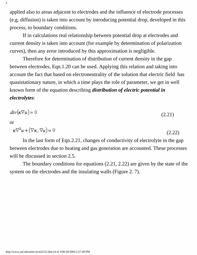
applied also to areas adjacent to electrodes and the influence of electrode processes (e.g. diffusion) is taken into account by introducing potential drop, developed in this process, to boundary conditions. If in calculations real relationship between potential drop at electrodes and current density is taken into account (for example by determination of polarization curves), then any error introduced by this approximation is negligible. Therefore for determination of distribution of current density in the gap between electrodes, Eqn.1.20 can be used. Applying this relation and taking into account the fact that based on electroneutrality of the solution that electric field has quasistationary nature, in which a time plays the role of parameter, we get in well known form of the equation describing distribution of electric potential in electrolytes:
(2.21) or
(2.22) In the last form of Eqn.2.21, changes of conductivity of electrolyte in the gap between electrodes due to heating and gas generation are accounted. These processes will be discussed in section 2.5. The boundary conditions for equations (2.21, 2.22) are given by the state of the system on the electrodes and the insulating walls (Figure 2. 7).
http://www.unl.edu/nmrc/ecm22/22.htm (4 of 10)6/18/2004 2:27:49 PM

2
Fig.2.7. Scheme for boundary conditions Now, let us assume that we have perfectly conducting electrodes which are connected with the external source of voltage U. Boundary conditions in these case are as follow:
on cathode i.e. tool-electrode;
on anode i.e. workpiece;
on insulating walls. The last condition expresses the fact that current does not flow by insulator. The anodic potential Ea and the cathodic potential Ec depend on current density, and
are determined by the sum of both the concentration and the activation overpotential for each electrode. Cathodic potential Ec is precisely described by Tafel’s equation:
http://www.unl.edu/nmrc/ecm22/22.htm (5 of 10)6/18/2004 2:27:49 PM

2
(2.23) for very wide range of current density, from 10-5 to 102 A/cm2. The value of the coefficient, a, depends on the material of tool electrode. The coefficient, b, is equal to 0.11-0.14 V for NaCl electrolyte, and 0.24V for NaClO3
electrolyte (ic, A/cm2) . Changes of Ec in comparison with voltage U are relatively
small, and we can assume in calculation, that Ec is constant. For example during
ECM in NaCl electrolyte, overpotential Ec is approximately equal 1.5V. In the case
of anode dissolution with high current density, Tafel’s equation is accurate only in some range of current density. Relation Ea = Ea(i), or i = i(Ea) in whole range in ECM of applied values of
current density is represented by more complicated curve. Figure 2.8 illustrates some examples of anodic polarization curves of nickel in 5M NaNO3 + 1M HNO3
solution at different electrolyte flow velocities [7].
http://www.unl.edu/nmrc/ecm22/22.htm (6 of 10)6/18/2004 2:27:49 PM

2
Figure 2.8. Anodic polarization curves for nickel at different electrolyte velocities [7]. The polarization curve Ea = Ea(i) as well as current efficiency of anodic dissolution
curve η = η(i) (or electrochemical machinability curve Kv(i)) are among the most
important characteristics of anodic dissolution. In some applications of ECM, the electric resistivity of electrodes cannot be neglected, for instance in large and thin workpieces. During flow of high current, the drop of voltage appears along the workpiece and there is a need to include this effect into the boundary condition. As can be seen from Eqn.2.20 and Eqn.2.22, electrical conductivity of the
medium between electrodes, κ, has influence on current density and electric potential field distribution. Experimental results as well as calculations show that changes of conductivity are one of the main reasons of machining inaccuracy. With respect to this, it is necessary to analyze variations in electrical conductivity in detail in real
http://www.unl.edu/nmrc/ecm22/22.htm (7 of 10)6/18/2004 2:27:49 PM

2
machining conditions.
It is necessary to differentiate variation of conductivity κ0 from inlet to
machining region from change of conductivity caused by physical processes in the gap. As it is known, the value of κ0 depends on concentration of
components in electrolyte solution, temperature at the inlet as well as degree of impurities resulting from the machining products in the electrolyte. Stabilizing this factor, by control of an electrolyte supply system, the values of conductivity could be maintained in the required tolerance of κ0.
Maintaining conductivity at inlet does not eliminate variation of conductivity κ in the interelectrode gap caused by phenomena accompanying the machining process. During current flow through the electrolyte, a considerable amount of heat is evolved, causing increase in temperature of electrolyte. Influence of temperature on the electrical conductivity is approximately given by:
(2.24)
where: αT is temperature coefficient of electrical conductivity at inlet temperature,
with values of 0.02 - 0.03 1/K for typical electrolyte used in ECM. Simultaneously due to heating, in most of the cases, gas bubbles are generated in the machining zone. The effective electric conductivity of gas-electrolyte dispersions may be substantially smaller than the conductivity of the bubble-free
electrolyte. Conductivity is directly correlated with the volume fraction β (void fraction) of the gas in dispersion. In the interelectrode gap β varies both across the gap and in the main electrolyte flow direction. The problem of the effective conductivity of a dispersion with uniformly distributed gas bubbles, interpreted as non-conducting spherical particles, has been
http://www.unl.edu/nmrc/ecm22/22.htm (8 of 10)6/18/2004 2:27:49 PM

2
treated for more than 100 years and continues to give a rise to renewed interest. There are numerous theoretical and some empirical equations for the effective
conductivity κ of a dispersion related to the conductivity of bubble-free electrolyte κe. Since a high content of bubbles in the gap is often encountered in
practice of ECM, the Bruggeman equation will be used:
(2.25) Taking into account the effect of both factors at the same time (relations given by Eqns.2.24 and 2.25), the effective conductivity of medium at given point of the gap can be obtained as:
(2.26)
where: Θ = T-T0 is increase temperature.
Taking Eqn.2.26 in the account in electric field equation (2.22) we can obtain:
(2.27) and from Eqns.2.20 and 2.26 current density is equal:
(2.28) Hence, we see new factors, in the form of distributions of temperature and void fraction, coming into the analysis. These distributions are not independent from each other and are not isolated from the different fields and physical conditions existing in the interelectrode gap. Fortunately, a further simplification describes sufficiently well many practical
http://www.unl.edu/nmrc/ecm22/22.htm (9 of 10)6/18/2004 2:27:49 PM

2
problems. Nevertheless, the solution of the above equations, with particular conditions and cases of ECM processes, is the subject of most of the research.
http://www.unl.edu/nmrc/ecm22/22.htm (10 of 10)6/18/2004 2:27:49 PM

2
2.3. The “ideal” ECM process.
The simplest approximate model, often called as a model “ideal” ECM process, is built on the following assumptions [2,5]:
● Ohm’s law holds over entire interelectrode gap up to surfaces of the electrodes.
● The electric conductivity of the medium in the gap remains constant in both time and space.
● At each electrode the potential remains the same over the entire surface area and through the machining time.
● Current efficiency for the anodic dissolution of the metal is the same at any point on the surface of the workpiece.
Basis on these four assumptions, the electrochemical shaping process is described generally as follows:
(2.29)
http://www.unl.edu/nmrc/ecm23/23.htm (1 of 14)6/18/2004 2:28:24 PM

2
Figure 2.9. Diagram for mathematical modeling of electrochemical shaping process When the anode surface is described by explicit function z = za(x, y, z) in the
Cartesian coordinate reference system {x, y, z} fixed to the workpiece (often stationary), as shown in Fig. 2. 6, the shaping process is described as follows:
(2.30)
Since under assumption (3), both the anode and cathode are equipotential surfaces, we can assume arbitrarily that the cathode potential equals zero. The cathodic
http://www.unl.edu/nmrc/ecm23/23.htm (2 of 14)6/18/2004 2:28:24 PM

2
overpotential Ec is included to the total overpotential ∆U = Ec-Ea. The formulated above mathematical model belongs to moving boundary problems (MBP). Many of the essential characteristics and features of ECM can be revealed by an analysis of the dynamic behavior of a number of the simplest systems. The conclusions drawn from such an analysis can be useful in practical considerations, as in the choice of machining parameters, electrode design, machining tolerances, and the limiting factors of the process. Major points discernible from the description (equations above) can be emphasized by solution of well-chosen one-dimensional problems. Although the solutions themselves have restricted applicability, the conclusions drawn from them can be useful. In particular those obtained for the one-dimensional MBP solution, bringing out the relationships, which control ECM, showing many important features of machining, which should be always considered in the more intricate cases.
2.3.1 Time dependence of interelectrode gap for plane parallel electrodes in one-dimensional case of ECM Let us consider a basic, simpler case of ECM, which is electrochemical machining done with a parallel, plane electrodes as shown in Fig. 2.10.
Fig.2.10. ECM with parallel, flat electrodes
http://www.unl.edu/nmrc/ecm23/23.htm (3 of 14)6/18/2004 2:28:24 PM

2
When two infinite parallel conducting planes, with a potential difference U applied across them, are a distance S apart, we see from symmetry that the intensity of electric field between them must be uniform and normal to the electrodes. In practice, the field will be uniform only far from the edges of the plate. Analysis of the distribution of the intensity field shows that the effects of the edge of electrode can be ignored where the distance from them is more than 2S. In this case, the gradient of potential is:
(2.31) and current density now becomes:
(2.32) where S = Za(t)-L(t) and L(t) describes the movement of the tool.
Substituting of Eqn.2.32 into Eqn.2.10 with respect, that:
We obtain differential equation, which describes the motion of the anode:
(2.33) with initial condition za = z0 at t = 0.
The solution of Eqn.2.33 depends on the functions U = U(t) and the motion of tool-electrode L= L(t).
2.3.2 Electrochemical machining with stationary tool-electrode The stationary tool-electrode is applied in many finishing operations and for deburring and radiusing of edges of machine parts.
http://www.unl.edu/nmrc/ecm23/23.htm (4 of 14)6/18/2004 2:28:24 PM

2
Taking L(t) = 0 to Eqn.2.33, after integrating with respect of initial condition, we can obtain:
(2.34) At constant working voltage U = U0 evolution gap in time, described by the well-
known expression [1,2,5]:
(2.35) where: D = kvκ(U0-∆U) can be called as a characteristic parameter of ECM with
stationary tool electrode. Eqn.2.35 has been applied in many approximate calculations of manufacturing operation, for example at surface leveling. This can be clarified by considering a following case.
Figure 2.11 Smoothing effect at ECM with stationary
Let us consider displacements of extreme points A and B on the anode-workpiece, which are shown in Fig.2.11. Assuming that dissolution of sections around of these occurs independently, we may apply Eqn.2.34 separately to them and obtain:
http://www.unl.edu/nmrc/ecm23/23.htm (5 of 14)6/18/2004 2:28:24 PM

2
or
(2.36) where: R is initial “roughness” of anode, ad R(t) is final “roughness” after time of machining t. The time tm required for removal of the allowance (allowed stock) of g, with a
stationary tool-electrode is given by:
(2.37) Expression (2.37) can be used for approximate determination of the machining time, as a function of ECM parameters, for manufacturing small cavities, grooves, rectangular patterns, etc. With gap increase, the current density decreases, according to expression as follows:
(2.38) where:
is initial current density. As a result of decreasing material removal rate, a decrease of current density results.
http://www.unl.edu/nmrc/ecm23/23.htm (6 of 14)6/18/2004 2:28:24 PM

2
If the power supply is working in constant current mode, the voltage increases with machining time, and material removal rate is approximately also constant.
2.3.3 Electrochemical machining with constant tool electrode feed rate The majority of ECM tool machines utilize constant feed of tool-electrode (Figure 2.12)
Figure 2.12. ECM with flat - parallel electrodes, and at constant feed rate of the tool electrode
For this case, the movement of the cathode with feed rate Vf is described by
and equ. (2.33) can be written
(2.39) With the initial condition za=z0 at t=0, consideration of the case with constant feed
involving voltage U=U0, this equation is made dimensionless by introducing the
http://www.unl.edu/nmrc/ecm23/23.htm (7 of 14)6/18/2004 2:28:24 PM

2
following non-dimensional coordinates:
and
where
(2.40) After rearrangement, Eqn. 2.39 in dimensionless form becomes:
(2.41)
at t=0, and . The solution of Eqn. (2.41) with repeat of initial condition is:
(2.42) Return of Eqn. 2.42 to dimensional coordinates we have:
(2.43) The changing in position of the anode during ECM with constant feed rate of tool electrode by Eqn 2.43 is shown in Figure 2.13.
http://www.unl.edu/nmrc/ecm23/23.htm (8 of 14)6/18/2004 2:28:24 PM

2
Figure 2.13. Changes in position of electrodes during ECM with constant feed rate of the tool electrode
Line 1 illustrates the position of the tool with time, and curves 2 and 3 show the changes of position anode boundary of two values of the initial gap with (2) Z0' and
(3) Z0'', with time. With the increase of Za, the term with the exponential function in
Eqn. 2.43 is decreasing and curves 2 and 3 go to an asymptote line.
(2.44) After some time process, dissolution practically stabilizes and the metal removal rates Vn becomes equal to the tool feed rate Vf. In other words, we can say that with
time, the gap size stabilizes on a steady state value, Sf, expressed by (2.40).
The steady state gap, Sf, is the key parameter of ECM with both a flat and a complex-
shaped tool fed with a constant rate. Directly, the change of gap between tool-electrode and anode workpiece can be described by introducing moving system coordinates, which are fixed with the tool. These coordinates are called tool system of coordinates (TSC) and are more convenient in many cases of analysis of ECM, in particular of tool design problems.
http://www.unl.edu/nmrc/ecm23/23.htm (9 of 14)6/18/2004 2:28:24 PM

2
Transformation of coordinates at motion of tool electrode parallel to axis Z is described by the following:
(2.45)
where ( ) are coordinates in moving system (TSC) and L(t) describes the
movement of the tool-electrode. Let us consider the above case , Eqn 2.39 in TSC transforms into the form:
(2.46) at t=0, S=S0.
Where we arbitrarily set for convenience, notice the gap size S. In non-dimemsional coordinates, Eqn 2.46 begins:
(2.47)
at t=0, .
where and .
Integration of Eqn. (2.47) with initial conditions we have:
(2.48) or in dimensional form:
http://www.unl.edu/nmrc/ecm23/23.htm (10 of 14)6/18/2004 2:28:24 PM

2
(2.49) This solution was first derived by Tipton in his classical analysis [6]. Change in gap in nondimensional coordinates at different values of initial gap size is shown in Figure 2.14.
Figure 2.14. Changes in gap size in non-dimensional coordinates Based on the plots in Figure 2.13, 2.14 and 2.17, the process of ECM with constant feed rate, or generally with constant of characteristics value Sf with time, may thus
be divided into:
● A transit state● A steady state
In the transit state, the current density, velocity of dissolution and gap size between electrodes are changing with time. Its values are reaching to some constant value as follows:
http://www.unl.edu/nmrc/ecm23/23.htm (11 of 14)6/18/2004 2:28:24 PM

2
In the steady state all parameters such as the current density, velocity of dissolution and gap size are constant with time. The time tm required to remove the machining allowance from a workpiece by a
moving tool (see Fig 2.16) can be determined from equation as fallows:
(2.50) Figure 2.15 and 2.16 illustrates the changes in value of gap size S, surface roughness average height Ra with time, obtained from computer simulation of an
electrochemical smoothing process.
Fig.2.15. Computer simulation of electrochemical smoothing process
http://www.unl.edu/nmrc/ecm23/23.htm (12 of 14)6/18/2004 2:28:24 PM
2
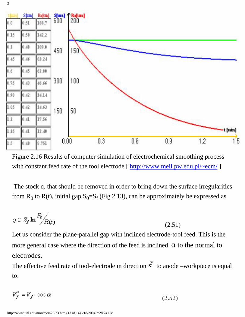
Figure 2.16 Results of computer simulation of electrochemical smoothing process with constant feed rate of the tool electrode [ http://www.meil.pw.edu.pl/~ecm/ ] The stock q, that should be removed in order to bring down the surface irregularities from R0 to R(t), initial gap S0=Sf (Fig 2.13), can be approximately be expressed as
(2.51) Let us consider the plane-parallel gap with inclined electrode-tool feed. This is the
more general case where the direction of the feed is inclined α to the normal to electrodes. The effective feed rate of tool-electrode in direction to anode –workpiece is equal to:
(2.52)
http://www.unl.edu/nmrc/ecm23/23.htm (13 of 14)6/18/2004 2:28:24 PM

2
Substitution of Eqn. 2.52 into Eqn. (2.39, 2.40, and 2.43) we can obtain description of dynamic gap for this case of machining. For example, steady state gap (i. e.
equilibrium gap), which is measured in normal direction , becomes
(2.53) The equilibrium gap Sn is increased with an increasing angle of inclination.
Obtained first by Tipton, “the cosines law” for gap size in steady state of ECM [6], described above by Equ. 2.53, is used extensively in tool-electrode design as a first approximation (see section 2.5). 2.3.4 Computer simulation of electrochemical shaping
Based on mathematical model of EC shaping process described by Eqns.2.30, for given shape of tool electrode and conditions of machining, computer simulation of evolution of workpiece profile can be carry out by using included software. Software includes simulation of:
● The changes gap size during ECM using stationary electrodes ● Smoothing process by observation of changes of high R of step on the
workpiece, during ECM using stationary electrodes● Evolution shape of workpiece in time during ECM with constant feed rate of
tool electrode
http://www.unl.edu/nmrc/ecm23/23.htm (14 of 14)6/18/2004 2:28:24 PM

2
2.4 Tool-electrode design
So far we have been dealing with ECM in an unsteady state when the part configuration varies with time and tends to some form asymptotically as can be observed by using computer simulation software. For example, in Figure 2.17 is shown asymptotical shape of workpiece i.e. in steady state ECM with using the circular tool electrode.
Fig. 2.17. Profile of workpiece in steady state ECM using circular tool electrode [http://www.meil.pw.edu.pl/
~ecm/]
Once the gap geometry is stabilized, ECM is said to have achieved a steady state – part configuration is no longer changing for all practical purpose because the work material at all points on the workpiece surface (A1, A2, A3, A4) is moving along feed tool direction at the same velocity equal to tool feed rate Vf (see Fig
2.18).
http://www.unl.edu/nmrc/ecm24/24.htm (1 of 5)6/18/2004 2:28:44 PM

2
Fig. 2.18. Distribution of dissolution velocity in steady state ECM process [2] Now the metal-removal rate (velocity of dissolution) Vn and the current density ia on the workpiece are given
by
(2.54)
(2.55)
where α is angle between normal to anode na and feed tool direction (Vf).
The equations (2.54) and (2.55) describe conditions of steady state ECM and are used for determination of anode-profile given the shape of tool electrode or shape of tool electrode at tool design, when is required given shape of workpiece. Electrochemical machining accuracy is greatly enhanced in a steady state. Therefore, if conditions permit, ECM should be carried out so that the required form of the part tends asymptotically to the surface generated under steady-state conditions. This will greatly reduce the number of factors affecting ECM accuracy (among other things, the shape of the part is no longer affected by irregularities in the blank, machining time, initial position of the electrodes, and the like). In determining the geometry of the tool to be used under steady-state conditions, the variables that should be specified in advance are the required shape of the surface to be machined, tool feed rate, applied voltage, the
electrochemical machinability KV of the work metal, the electric conductivity κ of the electrolyte, and value
of anodic and cathodic polarization Ea, and Ec, respectively.
The design procedure for the tool shape can be simplified by resorting to a method based on the linearization of the potential distribution across the gap width. With this method, one assumes that in the vicinity of a given point the electric field is locally one-dimensional, that is, it is about the same as one existing in a plane-parallel gap. The actual line of current (the dashed line in Fig 2.19a) is replaced with a straight-line segment,
http://www.unl.edu/nmrc/ecm24/24.htm (2 of 5)6/18/2004 2:28:44 PM

2
AC′ or AC′′, which is perpendicular to the surface of the workpiece or to the surface of the tool (the solid line in Fig. 2.19a). This approximately is legitimate for workpieces with a small radius of curvature, R, such that , and if the angle α does not exceed 75°. This leads us to an equation widely used in practice. With it, the form of the tool can be found graphically or analytically (see Eqn. 2.53):
The graphical construction of the tool profile, using straight-line segment AC′ as an, is shown in Fig. 2.19b.
a) b) Fig.2.19. (a, b) Diagram for tool electrode design procedure
The value of Sf can be chosen according to the maximum current that can be supplied by the power unit.
Under steady-state conditions the total current is given by
where,
An is the surface area of a projection of the part onto a plane perpendicular to the tool feed rate vector. Since
current I cannot be greater than the maximum current supplied by the power unit, we have
(2.56)
http://www.unl.edu/nmrc/ecm24/24.htm (3 of 5)6/18/2004 2:28:44 PM

2
The conductivity κ is assumed to have the values obtaining at the average temperature of electrolyte during machining process. Application of “cosines law” for determination of profile of tool electrode for ECM of airfoils is shown in Fig 2.20.
Fig. 2.20. Diagram for tool design for ECM of the airfoil (blade) The coordinates of tool electrode profile can be calculated as follows: (2.57) where y=F0(x) is required shape of workpiece.
Typical materials used for the tool electrode are presented in Table 4 Table 4. Materials for the tool electrode [21].
http://www.unl.edu/nmrc/ecm24/24.htm (4 of 5)6/18/2004 2:28:44 PM

2
http://www.unl.edu/nmrc/ecm24/24.htm (5 of 5)6/18/2004 2:28:44 PM

2
2.5 The “Non-Ideal” ECM Process
In practice, ECM is never ideal. In consequence, the metal-removal rate is distributed over the surface of the workpiece in a different way (the current in a real ECM process is not inversely proportional to the gap size), and the part takes on a form different from that found by design. This difference can be analyzed from variations in Sn in the direction of electrolyte flow.
This difference in the gap size Sn can be estimated from variation in the equilibrium gap along the
electrolyte flow direction. As the electrical conductivity k increments by Dk, the coefficient of
electrochemical machinability Kv by DKv, total overpotential DU by DE (that is, by the respective internal disturbances in the gap and on the electrode surface), we can find that the relative change in the equilibrium gap at angle a is approximately given by
(2.58)
If we additionally consider external disturbances (variations in applied voltage V and tool feed rate vf), the
respective terms should be added to the right-hand side of Eqn. (2.58).
Equation (2.58) may be used for an approximate analysis of ECM accuracy and tool shape adjustment. The internal disturbances are functions of coordinates and – in an unsteady state of time.The electrical conductivity if the medium filling the gap is given by Eqn.2.26.As is seen, in order to determine Dk/k0, we need to know the distribution of temperature and gas content of
gap.
Fig. 2.21 Effect of the hydrogen and heat generation on the distribution of the equilibrium gap size Let us see, in qualitative terms, how electrolyte temperature and gas control affect the distribution of local metal-removal rates in a plane-parallel gap (Fig. 2.21). The hydrogen evolving at the tool produces a two-
http://www.unl.edu/nmrc/ecm25/25.htm (1 of 4)6/18/2004 2:28:53 PM

2
phase layer (consisting of electrolyte and hydrogen bubbles) at the electrode gaining in depth in the electrolyte flow. Given certain conditions, this layer may fill the entire gap. In computations, it is customary to invoke the concept of average gas content, b, at a given gap section. If, however, one uses hg, it is usual to
deem that e remains constant along the y-axis and to assume that b= 0.5.
The ECM of large-sized workpieces involves large gaps, in which the gas bubbles generated at the tool may extend as far out as the surface of the part and merge together, thus increasing the value of b. In the long run, this may disturb the stability of electrolyte flow in the gap and produce pulsation. If these events are allowed to develop too far, the ECM process may cease altogether.
The passage of current through the electrolyte generates an appreciable quantity of heat, Q. It can conveniently be expressed by internal heat generation rate per unit volume: (2.59) Changes in the properties of the medium filling the gap entail changes in the pattern of heat generation (Fig. 2.21 b): the medium near the cathode loses some of its electrical conductivity and this brings on an abrupt rise in heat generation; where the electrolyte remains free from impurities, the reverse is true. Typically, there appear peaks of temperature at the electrodes owing to a slow-down of electrolyte flow. Indeed, because of the increase in heat generation the tool may have a temperature much higher than that of the work-piece. The temperature of the electrolyte falls off to become equal to that of the electrodes owing to heat withdrawal through the latter.
Changes in temperature, gas control and, as a consequence, electrical conductivity have as their result a change in the steady-state gap, Sf , and an impairment in the form of the machined part. Notably, the
machining of a flat workpiece with a flat tool may produce a curved surface on the finished part (see Fig 2.21a). The gap will exceed Sf when heat build-up is predominant, and it will be smaller than Sf when gas
content has a greater effect. The size of the actual equilibrium gap, Sf (x), or the change in the steady-state
gap, DS, can be determined, using the distribution of mean temperature T, and of mean gas content, , found for the mean velocity of electrolyte, w.
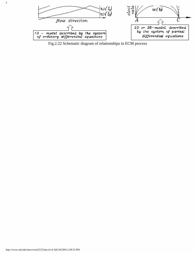
Figure 2.22 qualitatively illustrates basic physical fields and machining conditions and their interrelationships having important bearing on the ECM process and summarizes the basic components of process characteristics connected with shaping by electrochemical machining at contoured electrodes. Inspection of the Figure 2.22 shows complex nature of shaping process and mathematical difficulties in solving field problems. Application of computer simulation techniques based on mathematical modeling is necessary for analysis of machining process and tool electrode design.
http://www.unl.edu/nmrc/ecm25/25.htm (2 of 4)6/18/2004 2:28:53 PM

2
http://www.unl.edu/nmrc/ecm25/25.htm (3 of 4)6/18/2004 2:28:53 PM
2
Fig.2.22 Schematic diagram of relationships in ECM process
http://www.unl.edu/nmrc/ecm25/25.htm (4 of 4)6/18/2004 2:28:53 PM

2
2.6 Mathematical Modeling of ECM sinking process The problem of determining the changes in shape of machining surface and physical conditions in the interelectrode gap for transit and steady state of the ECM with using contoured cylindrical tool-electrode is considered in this section (Fig.2.23.) [8]. The electrode flow is from left to right in a thin gap of local size S and of length L. The down surface is the tool-electrode which moves upward with feed rate Vf. At a point opposite the tool, the workpiece
surface is moving upward with local velocity Vn. In steady state ECM with using the curvilinear tool-
electrode the value Vn is equal Vf×cosa This distribution of the velocity of dissolution and the change of
physical conditions along the flow path evoke non-uniform distribution of the gap size S and a shape error of the workpiece-anode.
Fig. 2.23. Schematic diagram for mathematical model of ECM sinking
The mathematical model of ECM process, referring to the formulated problem consists of sequence of mutual conjugated partial models, which describe in the gap:
● distribution and change in time of the local gap size S,● distribution of the flow parameters ( the static pressure p and the velocity w),● distribution of the temperature T, ● distribution of the void fraction b (volumetric gas concentration) or the thickness layer with two
phase flow (electrolyte and gas) h.
http://www.unl.edu/nmrc/ecm26/26.htm (1 of 7)6/18/2004 2:29:14 PM

2
The physical model with the following assumptions serves as the basis for mathematical modeling [8]:
1. The three regions can be identified in the gap: 1- the region with pure electrolyte, 2- the bubble region near cathode with thickness h < S and which consist of mixture of electrolyte and gas (hydrogen), where the void fraction of hydrogen in the bubble region layer is constant and equal b*, 3 - the region of two phase flow with change of b,
2. The current density i is dependent on medium conductivity in the gap and on the voltage U according to Ohm’s law, which is extrapolated to the whole gap size. The electrochemical reaction will be accounted for by introducing total overpotentialE = Ea - Ec, where Ea and Ec are the potential of anode and cathode, respectively,
3. The surface tension effect on the gas bubbles is neglected, and so is the bubble formation time, 4. Since analytical models of Kv = Kv(i) and E = E(i) are not available, experimental results are used
with theoretical model, 5. The effect of bubble layers on pressure and the flow velocity of the electrolyte is accounted by
consideration of a homogeneous two-phase model flow, where the electrolyte in the gap is treated as a uniformly-mixed pseudo-continuous medium of gas and liquid with local average void fraction:
0<h<S (2.60)
6. The electrical conductivity of the two-phase medium can be determined by the Bruggeman equation (2.26):
where: q = T - To, To = inlet electrolyte temperature,
aT = the temperature coefficient of the electrolyte conductivity at To, and
ko = electrolyte conductivity at To and b = 0.
To simplify the calculations let us introduce a curvilinear coordinate system (x,,z), connected with the tool-electrode in which a coordinate x lies on the given electrode and is measured from the inlet of the
electrolyte and let axis z overlap its normal (Fig. 2.36).To formulate the mathematical model, a general case describing change in shape of the surface of the workpiece can be examined using a coordinate system attached to the workpiece, which is immovable during machining (Fig. 2.23). The surface of the workpiece at a given moment in time can be described by: z = Z(x, y, ). According to electrochemical shaping theory, the evolution of the shape of the
http://www.unl.edu/nmrc/ecm26/26.htm (2 of 7)6/18/2004 2:29:14 PM

2
workpiece F(x, y, t), can be described as follows (see Eqn.2.10):
(2.61)
At the beginning of machining: t = 0, z = z0(x, y), where: z0(x, y) describes an initial shape of the
workpiece surface. To find the current density iA on the surface of the workpiece, approximation using linearization of
electric potential distribution along the segments of distance d between a given point of anode and given point on the TE can be applied. The current density can be obtained by Ohm’s law with respect of change of conductivity across the gap:
(2.62)where:
(2.63) The equation of mass conservation for the hydrogen generation in the curvilinear coordinates can be obtained from mass balance as:
(2.64)where:
- specific gas density of hydrogen,
R = gas constant for 1 kg of hydrogen,
hH = current efficiency of the hydrogen generation,
KH = electrochemical equivalent of hydrogen,
- average velocity in the given cross section of the gap. The heat transfer in the gap with respect to Joule’s heat is described by:
http://www.unl.edu/nmrc/ecm26/26.htm (3 of 7)6/18/2004 2:29:14 PM

2
(2.65) where: a - thermal diffusivity, aT - turbulent thermal diffusivity by turbulence pulses (for laminar flow
aT = 0), r - specific medium density (in the region 1 r = re, and in the region 2 and 3
where re - density of electrolyte) and Cp - specific heat of electrolyte.
The boundary conditions are as follows: T(x=0) = To, T(x, 0) = TA, T(x, S) = TC, where: TA and TC are
temperatures of the anode and cathode, respectively. To complete the systems of Eqs. (2.61) - (2.65), the formulation the pressure and the flow rate must be included. The continuity equation can be expressed by:
(2.66)
where: - average velocity and gap size in inlet, respectively. The momentum balance equation for the moving control is:
(2.67) where: ta and tc are the shear stresses on the surfaces of anode and cathode, which are assumed to be
equal (ta = tc). In general, the shear stress is expressed as follows:
(2.68)
where , is Reynolds number (for laminar flow: C=96 and m=1; for turbulent: C=0.316, m=0.25). The boundary conditions for Eqn. (2.68) is described by:
http://www.unl.edu/nmrc/ecm26/26.htm (4 of 7)6/18/2004 2:29:14 PM

2
; ,
where: is the hydraulic loss pressure in inlet and outlet, respectively. The system of Equations (2.61) - (2.68) has been solved numerically using the Finite Difference Method and iterative procedure. In the first iteration one-dimensional approximation has been used for distribution of temperature and for determination of change of thickness the bubble layer h(1), next this distribution of h(1) was used in the second iteration and in the first approximation of two-dimensional (2-D) calculation of temperature distribution. Calculation of a given iterative cycle are finished, when the criteria of accuracy of calculation is satisfied and the simulation ECM process culminates in printout and plots of: gap distribution and distributions of p, w, T, b. The sample of results are shown in Figure 2.24,and 2.38.
Fig. 2.24. Distribution p ,w, b =B , S along the flow path
http://www.unl.edu/nmrc/ecm26/26.htm (5 of 7)6/18/2004 2:29:14 PM
2
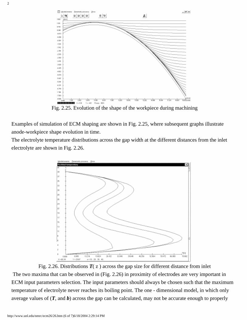
Fig. 2.25. Evolution of the shape of the workpiece during machining
Examples of simulation of ECM shaping are shown in Fig. 2.25, where subsequent graphs illustrate anode-workpiece shape evolution in time.The electrolyte temperature distributions across the gap width at the different distances from the inlet electrolyte are shown in Fig. 2.26.
Fig. 2.26. Distributions T( z ) across the gap size for different distance from inlet The two maxima that can be observed in (Fig. 2.26) in proximity of electrodes are very important in ECM input parameters selection. The input parameters should always be chosen such that the maximum temperature of electrolyte never reaches its boiling point. The one - dimensional model, in which only average values of (T, and b) across the gap can be calculated, may not be accurate enough to properly
http://www.unl.edu/nmrc/ecm26/26.htm (6 of 7)6/18/2004 2:29:14 PM

2
estimate the maximum temperature. Use of input parameters from simulation that underestimated electrolyte temperature for actual machining may lead to short-circuit between electrodes and, what follows, to damage of tool and workpiece.
The software developed in this study is a very efficient tool, supporting process design by computer simulation of ECM process. During analysis of results of computer simulation of ECM at different operating parameters, the critical condition can be determined from the point of view of the process limitations such as: boiling, choking flow (Mach number » 1) and cavitation.
http://www.unl.edu/nmrc/ecm26/26.htm (7 of 7)6/18/2004 2:29:14 PM

2
2.7 Pulse Electrochemical Machining (PECM) The approximate analyses of Eqn.2.58 and ECM practice led to the conclusion that machining inaccuracy is proportional to the gap size. The shape error is dependent on deviation of properties in the gap medium and physical conditions, such as electrical conductivity, temperature, void fraction, current efficiency (electrochemical machinability), flow velocity, pressure etc. Therefore, for improvement of shape accuracy and simplification of tool design, the gap size during ECM should be as small as possible. Additionally, more stabilization of the gap state is needed by reducing non-uniformity of electrical conductivity and other physical conditions, which are significant for the dissolution process. All these requirements for ECM performance, with continuous working voltage, is very limited. The minimum practical tool gap size, which may be employed, however is constrained by the onset of unwanted electrical discharges. These short electrical circuits reduce the surface quality of the workpiece, and led to electro-erosive wear of the tool-electrode, and usually machining cannot progress because of them. Investigations of electrical discharges in an electrolyte reveal that the probability of electrical breakdown in the gap is a function of the evolution of gaseous-vapor layers and passivation of the work surface. Intense heating, hydrogen generation sometimes choking phenomena and cavitation within the gap can lead to evaporation and subsequent gas evolution, and it is this gas which is believed to cause the onset of electrical discharge. The issue of heating of electrolyte is of primary importance for the determination of limit conditions of ECM process. The distribution of mean temperature in the inter-electrode gap along the flow was determined using one-dimensional mathematical model of ECM process. Further specification of temperature distribution was revealed [8]. Due to the heat exchange through electrodes as well as distribution of electrode, the temperature changes along the flow path as well as across the gap size.
http://www.unl.edu/nmrc/ecm27/27.htm (1 of 8)6/18/2004 2:29:24 PM

2
Fig.2.27. The steady distribution temperature in the gap with size S = 0.1 [mm] (U=9
[V], E=3 [V], flow rate 6 [m/s], electrolyte: 12% NaNO3
The electrolyte temperature distributions across the gap width, at the different distances from the inlet electrolyte in ECM process with small inter-electrode gap size S=0.1 [mm] is shown in Fig.2.27. The one or two maximum temperature that can be observed in proximity of electrodes are very important in ECM input parameters selection. The input parameters should always be chosen such that the maximum temperature of electrolyte never reaches its boiling point. A one - dimensional model, in which only average values of (T) and (b) across the gap can be calculated, may not be accurate enough to properly estimate the maximum temperature. For example, in the Fig.2.27, the maximum average increment of temperature is DTav=32 [0C], in this time, maximum temperature, as shown in Fig.
2.27 is DTmax=46.5 [0C].
Decrease of temperature below boiling point and decrease of void fraction by
http://www.unl.edu/nmrc/ecm27/27.htm (2 of 8)6/18/2004 2:29:24 PM

2
increase of flow velocity to a higher value is limited by the occurrence of cavitation in the gap, which leads to hydrodynamic defects of machined surface and unstable machining process. All these constrains of continuous ECM can be eliminated and the requirements with view of points of machining accuracy can be achieved by application of pulse working voltage in the electrochemical shaping and smoothing [2, 5. 9]. Additional positive effects can be added by the introduction of special complicated controlling movement of the tool electrode. In the result, the continuous ECM is replaced with a discrete process (PECM), which makes it possible to reduce the gap size below 0.1 [mm], and to set the gap size intermittently by controlling (monitoring) the position of the machining surface during the pause between pulses [9 - 13]. As has been noted, that replacement of continuos working voltage with pulsating voltage for ECM can facilitate the control of the process through a change in the distribution of overpotential and current efficiency (i.e. coefficient of electrochemical machinability) over the machining area. It may further be noted that the use of a pulsating voltage for ECM offers added opportunity for control of electrical conductivity distribution in the machining gap. Pulse ECM can substantially reduce DSn (see Eqn.2.58) if the applied voltage
pulses are short enough for the electrical conductivity of the medium in the gap to change slightly and to be fully restored to its original value between pulses in pulse off time. From an approximate analysis of how the electrical conductivity of the electrolyte is distributed in the gap after power turn-on, several conclusions of practical importance can be drawn with regard to the effect produced by the changes of the electrical conductivity of the medium on the distribution of local metal removal rate over the machining area. Practice and investigations shows that introducing PECM allows:
● Diminishing the inter-electrode to below 0.1 [mm], what is one of the fundamental condition of increasing ECM accuracy,
http://www.unl.edu/nmrc/ecm27/27.htm (3 of 8)6/18/2004 2:29:24 PM

2
● Reducing the inaccuracy of the machined profile caused by internal disturbance of physical and chemical properties of electrolyte (more exact: medium in the gap) in inter-electrode gap,
● Simplifying of tool design since the much more uniform distribution of the gap size,
● Eliminate the macro - defects on the machined surface connected with the hydrodynamic flow disturbances,
● Monitoring and control the gap sizes on line i.e. during the machining cycle.
All these problems have been investigated theoretically and experimentally. In the pulse ECM process, a pulse generator is used to supply the working voltage pulses across the two electrodes, typically in the form of pulse strings consisting of single pulses or grouped pulses (Fig. 2.28).
Fig.2.28. Principal scheme of PECM
The anodic electrochemical dissolution occurs during the short pulse on-times, each raging from 0.1 ms to 5 ms. Dissolution products (sludge, gas bubbles and heat) can be flushed away from the inter-electrode gap by the flowing electrolyte during the pulse off-times between two pulses or two groups of pulses. To
http://www.unl.edu/nmrc/ecm27/27.htm (4 of 8)6/18/2004 2:29:24 PM

2
intensify the electrolyte flushing, the tool is retracted from the workpiece to enlarge the gap during the pulse off-times. The gap checking and tool repositioning can also be conducted during these pulse pauses to establish a given gap size before the arrival of the next pulse, leading to a significant reduction in the indeterminacy of the gap and, hence, of the shaping accuracy. Existing work on PECM has shown considerable improvements in dimensional controllability, shaping accuracy, process stability, and simplification of tool design. With PECM, it is possible to reproduce complex shapes, such as dies, turbine blades, and precision electronic components, with accuracy within 0.02-0.10 [mm]. From theory and practice of PECM it follows that the pulse-off time should be long enough, firstly, for the gas and heat to be removed from the gap, secondly, for the metal to revert from activated to the passive state. As for the second point, to this end it was proposed to apply small pulses of the reverse polarity between the high-power working pulses. To eliminate the variations in the medium conductivity along the interelectrode gap in the direction of electrolyte flow, the larger the distance between the gap inlet and outlet, the longer should be the pulse-off time. In the machining of large-sized parts, the pulse-off time should be so long that the ECM productivity becomes too low. To overcome this drawback of pulsed ECM, special pulsed-cyclic regimes were elaborated, where the processes of metal removal and washing of inter-electrode gap are separated in time. The distance between the TE and WP varies according to a given relationship. A voltage pulse is applied in synchronism with the electrode movement. When the inter-electrode distance is small, the machining is performed with using usually the group pulses. The electrolyte flow rate in this small gap is usually low. When the distance is large, the gap is washed with intensive electrolyte flow. Under these conditions (a large gap), washing may be performed rapidly and the pulse-off time should not be too long. In this case, it becomes possible to perform ECM with very small gaps (several hundredths parts of a millimeter) enabling one to gain high accuracy of ECM. ,The term “Pulse Electrochemical Machining” includes several modifications of
http://www.unl.edu/nmrc/ecm27/27.htm (5 of 8)6/18/2004 2:29:24 PM

2
realization of discrete electrochemical shaping. Existing methods and schemes of PECM depend on a number of controlled factors, and they can be divide into the following group:
● according to kinematics of the tool electrode and the workpiece,● according to control systems,● according to shape of pulses and its distribution in time.
Fig.2.29. Schematic diagrams of working cycle of ECM and the curves of changing process parameters: (1)-feed rate of tool electrode v, (2)-flow velocity w,
(3)-current density j
Figure 2.29 presents the schematic diagrams of changes main parameters of continuous and discontinuous Electrochemical Machining processes. In continuous ECM illustrated by Fig.2.29 a, and Fig. 2.29 b, the working voltage and the inlet pressure is constant during relative long time of machining. The total
http://www.unl.edu/nmrc/ecm27/27.htm (6 of 8)6/18/2004 2:29:24 PM

2
machining process can be divided on sequences of steps with changed parameters. For example, the feed rate of tool electrode and voltage are set initially high, but are stepped down over the process cycle to obtain better conformance of the workpiece shape to that of the cathode and to avoid short circuit when active machining area is increasing with depth of cut. An improvement of accuracy and reducing of correction of tool electrode can be achieved only by vibration of the tool or the workpiece, what is shown in Fig.2.29 b The application of vibration movement with frequencies from tens Hz to tens kHz (for example, at constant working voltage), increases of a slope of the function current density vs. gap size. Finally it leads to increasing anodic localization and uniformity of the gap size distribution. Fig.2.29 c illustrates diagram of the Pulse Electrochemical Machining with vibrating tool electrode (or workpiece). In this variant of machining are used short voltage pulses in the period, when the gap size is smallest. Applications of vibrating PECM allowed the accuracy of 0.01 - 0.1 [mm]. Diagram of changes in the parameters in ECM with using sectional tool electrodes is shown in Fig.2.29 d. The individual sections are supplied by working voltage separately, depending on used control procedures. For example, in the moment tn
can be supplied this section, which is more closed to the workpiece surface. This variant of ECM is usually used for machining of large parts. Typical the pulse on time is from few seconds to tens of seconds. For decreasing changes of physical conditions in the gap due to forced flow of electrolyte, stationary electrolyte can be used during pulse on time, what is shown in Fig.2.29 e. In practice, the tool electrode is also stationary in this moment. For example, in ECM of crankshaft connectors, with using stopped forced flow during pulse working voltage, shape accuracy of 0.15 [mm] at gap size of 0.1-[mm] was obtained. Fig.2.29 f shows further development of ECM with pulsation flow electrolyte is used alternating pulses of flow velocity.
http://www.unl.edu/nmrc/ecm27/27.htm (7 of 8)6/18/2004 2:29:24 PM

2
In former Soviet Union countries, cyclic ECM with discontinuous (discrete) motion of tool electrode and working voltage (Fig.2.29 g) is used widely. In the period of pulse off time, reposition of tool electrode is used for increased flushing and monitoring of the gap size by a touching procedure. After touching and recognition of position of surface of workpiece, the gap size is set up before the next working pulse. Pulse off time is from a few seconds to tens of seconds, therefore, anodic dissolution is provided in almost the same conditions as continuous ECM. For this variant of ECM, the term cyclic ECM is usually used. Finally, Fig.2.29 h illustrates courses of parameters in PECM with complex motion of tool electrode, what is a further development of a previous scheme (Fig.2.29 g) by application of short pulses of working voltage or pockets of these pulses.
http://www.unl.edu/nmrc/ecm27/27.htm (8 of 8)6/18/2004 2:29:24 PM

2
2. 8 Surface Roughness and Layer Integrity after Pulse Electrochemical Machining
ECM and PECM are performed without physical contact between the tool and the workpiece in contrast to mechanical machining, and without strong heating in the machining zone in distinction to the methods like EDM. Therefore, no surface metal layer undergoes mechanical distortion, compressive stresses, cracks, and thermal distortion forms in ECM. Electrochemical machining methods are often used even for removing a defective layer, which has been formed, for example, in EDM, with the aim to improve the surface integrity. However, sometimes the intergranular attack occurs in various ECM methods. This may reduce the performance of machined parts. For example, Figure 2.30 illustrates appearance of intergranular attack at machining nickel - chromium heat resistance alloys (Figure 2.30 a). An “inverse” results are observed at machining of pure iron, when evolution of pitting lead to appearance of the some peaks on machined surface (Fig. 2.30 b). In both cases, the applications of Pulse ECM is effective way for improving of quality of the surface.
Fig. 2.30. Profiles of surface roughness after continuous ECM (1) and Pulse ECM (2) of special alloys Inconel (a), and iron (b) in 8% NaCl at current density, [A/cm2]: (1) 20, (2) 60 [13]
The workpiece surface roughness after PECM like in ECM with continuous current depends
http://www.unl.edu/nmrc/ecm28/28.htm (1 of 6)6/18/2004 2:29:34 PM
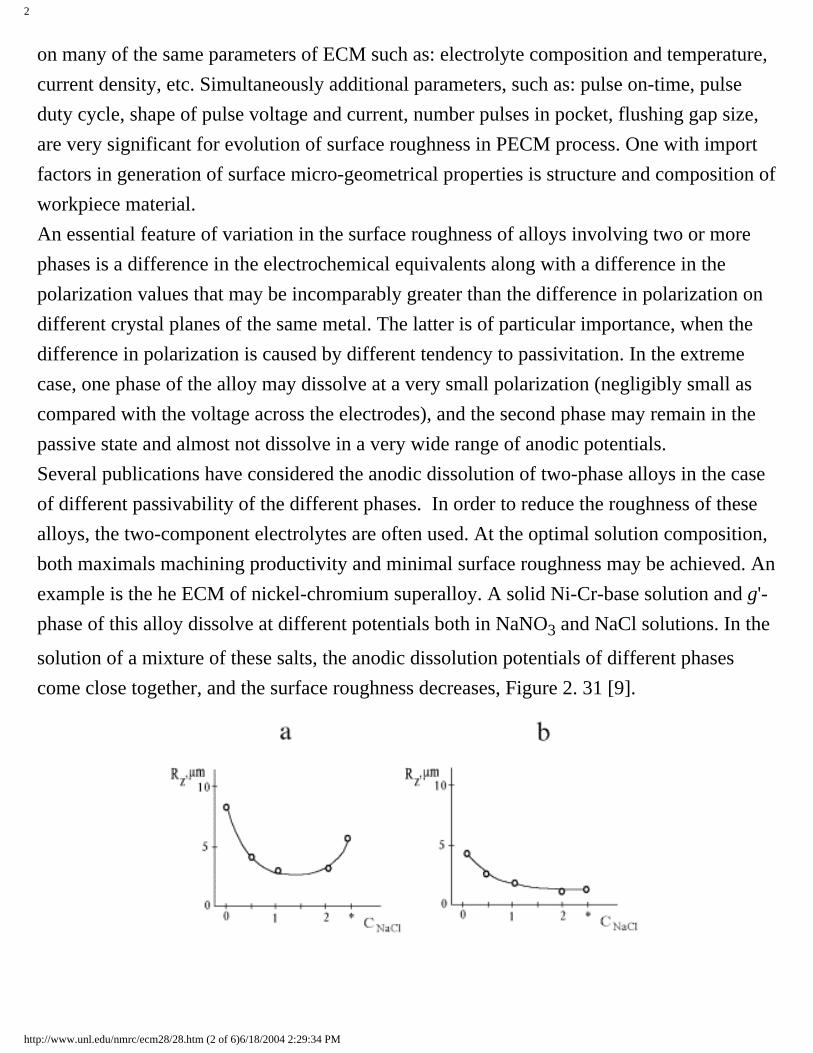
2
on many of the same parameters of ECM such as: electrolyte composition and temperature, current density, etc. Simultaneously additional parameters, such as: pulse on-time, pulse duty cycle, shape of pulse voltage and current, number pulses in pocket, flushing gap size, are very significant for evolution of surface roughness in PECM process. One with import factors in generation of surface micro-geometrical properties is structure and composition of workpiece material. An essential feature of variation in the surface roughness of alloys involving two or more phases is a difference in the electrochemical equivalents along with a difference in the polarization values that may be incomparably greater than the difference in polarization on different crystal planes of the same metal. The latter is of particular importance, when the difference in polarization is caused by different tendency to passivitation. In the extreme case, one phase of the alloy may dissolve at a very small polarization (negligibly small as compared with the voltage across the electrodes), and the second phase may remain in the passive state and almost not dissolve in a very wide range of anodic potentials. Several publications have considered the anodic dissolution of two-phase alloys in the case of different passivability of the different phases. In order to reduce the roughness of these alloys, the two-component electrolytes are often used. At the optimal solution composition, both maximals machining productivity and minimal surface roughness may be achieved. An example is the he ECM of nickel-chromium superalloy. A solid Ni-Cr-base solution and g'-phase of this alloy dissolve at different potentials both in NaNO3 and NaCl solutions. In the
solution of a mixture of these salts, the anodic dissolution potentials of different phases come close together, and the surface roughness decreases, Figure 2. 31 [9].
http://www.unl.edu/nmrc/ecm28/28.htm (2 of 6)6/18/2004 2:29:34 PM

2
Fig. 2.31. Effect of NaCl content (mole/l) cNaCl in the mixture with 2M NaNO3 on the
surface roughness of the nickel-chromium alloy after the ECM at (a) 10 and (b) 70 A/cm2 [19]. The main components of the alloy: the Ni base, 20% Cr, 2.5% Ti, 0.8% Al, 0.6% Si, 0.3% Mn. 2M NaCl solution free of NaNO3 is starred on the concentration axis.
A difference between the electrochemical dissolution rates of the materials of grains and grain boundaries is of great importance for ECM. The intergranular attack is one of the most dangerous consequences of ECM. The anodic dissolution of metals is a rather structure-sensitive method. (It is known that electrochemical dissolution is used widely in metallography for revealing the alloy structure and determining the phase composition.) We have already touched on the effect of alloy structure on the anodic dissolution rate. This factor is of importance also for the surface finish after ECM. For example, for a series of titanium-based alloys it has been shown that the preliminary heat treatment of alloys, leading to the fine-grained structure, assures low roughness after ECM. The operating conditions, which give large-grained structure, lead to the high roughness after ECM. A decrease in the grain size of carbon steel (0.42% C) by heat treatment leads to a decrease in the surface roughness of the workpiece. This is especially pronounced at not very high electrolyte flow rates. An increase in the flow rate leads to a decrease in the roughness and at ve> 15 m/s, the effect of grain size on the
roughness becomes insignificant. In PECM, flow velocity at using a small gap size is low and uniform in comparison with ECM, leading to the decreasing probability of the occurrence of hydrodynamic defects on the surface and to lower roughness.
http://www.unl.edu/nmrc/ecm28/28.htm (3 of 6)6/18/2004 2:29:34 PM

2
Fig.2.32. Relation between the average surface roughness Ra and pulse current density Da
(distance 35 [mm] from the inlet, 1-for continuous current, 2-for pulse current) [19]
The experiment shows that sensitivity of surface roughness on change current density in PECM of stainless steel, is less in comparison with the ECM process [19] (Figure 2.45 and 2.46). In other cases of materials of workpiece and conditions of PECM, the influence of the current density on average roughness Ra can be different, what is shown in Fig. 2.33.
http://www.unl.edu/nmrc/ecm28/28.htm (4 of 6)6/18/2004 2:29:34 PM
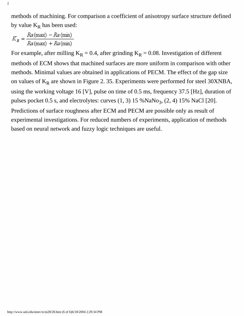
2
methods of machining. For comparison a coefficient of anisotropy surface structure defined by value KR has been used:
For example, after milling KR = 0.4, after grinding KR = 0.08. Investigation of different
methods of ECM shows that machined surfaces are more uniform in comparison with other methods. Minimal values are obtained in applications of PECM. The effect of the gap size on values of KR are shown in Figure 2. 35. Experiments were performed for steel 30XNBA,
using the working voltage 16 [V], pulse on time of 0.5 ms, frequency 37.5 [Hz], duration of pulses pocket 0.5 s, and electrolytes: curves (1, 3) 15 %NaNo3, (2, 4) 15% NaCl [20].
Predictions of surface roughness after ECM and PECM are possible only as result of experimental investigations. For reduced numbers of experiments, application of methods based on neural network and fuzzy logic techniques are useful.
http://www.unl.edu/nmrc/ecm28/28.htm (6 of 6)6/18/2004 2:29:34 PM

3
3. ECM EQUIPMENT [5] A state-of-the-art ECM system is the art of assemblage of facilities including a proper ECM machine, a power supply, a process parameter control system, and an electrolyte preparation, feed and purification system. The parts that are machined with ECM usually widely differ in shape and size, the amount of stock to be removed, and in lot size. This therefore affects the design of ECM machines. They may be universal, special-purpose, and single-operation. Universal ECM machines, as their name implies, are capable of performing a wide range of operations. They include duplicating and duplicating-hole drilling machines. When designing these machines, it is important to consider the size of the workpieces because this factor determines the forces that will act upon the machine elements during ECM. The tooling scheme should be chosen according to the rigidity of the base, the form of feed drive, and some other aspects. It is important that the operator should feel comfortable when he sets up or takes down a workpiece, clamps it in a fixture, etc. The above factors should be considered when making the decision to arrange the machine horizontally or vertically, to use a fixed or a movable (extendable) machine table, and where to locate the feed drives. The degree of automation to be provided in a machine usually depends on the contemplated lot size. Fully automated facilities are indicated for large-size manufacturing, as for deburring in the automotive industry. Units have been developed in which all operations, from blank feeding to applying a rust-preventive compound to finished parts, are automated. Such units can turn out as many as several hundred parts every hour. Most ECM machines operate in what may be called a semi-automatic mode. In them, the ECM cycle is properly automated, but blanks are set up, aligned and clamped, and finished parts are taken down by a human operator. He also starts the machine and its ancillaries. The facility is stopped automatically on reaching the specified dimension or depth of machining. How accurately an ECM machine and its subassemblies (the feed drive, the
http://www.unl.edu/nmrc/ecm3/3.htm (1 of 5)6/18/2004 2:29:41 PM

3
guideways, and the quill) are manufactured, the feed drive is stopped on reaching the specified depth of machining, and the workpiece is aligned relative to the tool electrode has a decisive bearing on ECM accuracy. The latter is also affected by the temperature and its distribution among the machine elements. Appreciable variations in the temperature of the machine assemblies, notably the movable ones, such as the feed drive, complicate the choice of dimensional tolerances for guideways and seals.
It is important where current is applied to the workpiece. When the work lead is placed closer to the machining area, there is a reduction in leakage currents, power losses, and electrolytic attack on the areas that are not to be machined. For this reason, the work lead should be terminated directly at the workpiece or the workholding device, and not at the machine table. Work leads are in permanent contact with a corrosive medium, and this affects the choice of a material for their manufacture. At a machining current of over 4.5 or 5 kA it is a good practice to use work leads made of flexible conductors enclosed in rubber hoses which carry cooling water. It should be remembered that work leads will usually be heated to anywhere between 40° and 60°C. They can be held in place by demountable joints (such as bolts) and permanent joints, either brazed or welded. The clamping pressure for demountable joints is a factor affecting the magnitude of contact resistance is different for different materials and ranges from 6 × 10⁵ N/m2 to 1.5 ×10⁷ N/m2. The electrolytes used for ECM widely differ in chemical composition, and this too affects the design of ECM machines. Since most electrolytes will attack metals, ECM machines should, in contrast to conventional machine-tools, be designed to stand up to this attack. Wherever and whenever possible, nonmetallic materials should preferably be used in ECM machines. Where, however, the prime consideration is strength or rigidity, use should be made of metals with nonmetallic coatings. As a way of reducing cost, it is a good plan to use reinforced concrete for machine bases. In such a case, the base is assembled from angle pieces, a knock-down formwork is set up around it, and concrete is poured in place. Metal pieces are
http://www.unl.edu/nmrc/ecm3/3.htm (2 of 5)6/18/2004 2:29:41 PM
3
then embedded in the concrete to serve as locating surfaces for the feed drives and the ECM chamber. After the concrete sets and hardens finally, these locating surfaces are given a finishing treatment. Reinforced concrete cuts down both the cost and time of fabrication of ECM machine bases. The key subassemblies of an ECM duplicating and hole drilling machine are a base, a C-frame or an upright carrying guideways and feed drives, and an ECM chamber. Large machines are of portal design and each has a base, uprights, and a cross-member carrying the quill. The base, uprights and cross-member can be cast or, though more seldom, welded. Welded units are used more seldom because they show warpage, even when they are annealed for stress relief, and this introduces inaccuracies into the operation of the subassemblies set up on the welded members. The ECM chamber is the heart of an ECM machine. It encloses a machine table with T-grooves, a work-holding device, the work, and the work leads. The quill carrying the tool electrode also enters the chamber. In ECM machines for turbine-blade manufacture, the chamber is formed by the blade being worked and the tool electrode. In planning, the overall dimensions of the ECM chamber in a duplicating and hole drilling machine are limited by the dimensions of the machine table (or the workpiece), and vertically by the maximum distance that must be left between the quill tip and the machine table for ease of servicing. Located at the bottom of the chamber are electrolyte drain ports connected to an intermediate or the main tank. For hydrogen removal, the chamber is connected to an exhaust ventilation system. The chamber wall facing the operator can be either lifted on vertical guide ways or swung open on hinges. In horizontal machines the chamber or the protective enclosure can be moved by a separate electric motor on guideways, thus giving access to the table and the quill so that the work-holding device, the work and the tool can be set up or taken down. Set-up motion can also be provided for the machine table, for which purpose various guides (such as dovetail guideways or a cross tool slider) may be used. Sometimes, an ECM machine is arranged so that in setting-up the table and the chamber move together. The top wall disengages from the rest of the chamber and moves upwards. This arrangement clears a large service area, and simplifies the design of the guideways and seals.
http://www.unl.edu/nmrc/ecm3/3.htm (3 of 5)6/18/2004 2:29:41 PM

3
The ECM chamber can be built to enclose an auxiliary (or back-pressure) chamber into which compressed air is admitted. The compressed air serves a two-fold purpose. Firstly, it stabilizes the run of the ECM operation. Secondly, it brings pressure to bear upon the quill, thereby reducing the load on the feed drive and the force acting on the drive and the base. Given the same standard machine size, one may then use a base and a feed drive of lower rigidity.
http://www.unl.edu/nmrc/ecm3/3.htm (4 of 5)6/18/2004 2:29:41 PM

3
Fig. 3.1 Block diagram of an ECM system: 1, voltage stabilizer; 2, gap control system; 3, tool feed rate controller; 4, displacement control system; 5, electrolyte parameter control system; 6, tool feed drive; 7, linear displacement sensor; 8, exhaust ventilation; 9, electrolyte transfer pump; 10, centrifuge; 11, electrolyte tank; 12, electrolyte supply pump; 13, machine table; 14, tool electrode; 15, rectifiers; 16, transformer; 17, voltage regulator. In block-diagram form, the arrangement of an ECM facility is shown in Fig. 3.1.
Here, block I is an ECM machine, block II is a power source with a fast-acting short-
circuit protection system, block III is an electrolyte preparation, feed and purification
unit, and block IV is process parameter control circuits.
http://www.unl.edu/nmrc/ecm3/3.htm (5 of 5)6/18/2004 2:29:41 PM

4
4. POWER SUPPLIES FOR ECM MACHINE TOOLS [5}
ECM machines are equipped with semiconductor rectifiers. The choice of a
particular circuit configuration depends on the nature of load, the rating of the
power transformer, and some other factors.
a) b) c) d) Figure 4.1 rectifier circuit configurations and current and voltage waveforms
The three-phase, center-tap connection (Fig 4.1a) is used in small-size power units
because the induced magnetization flux in the transformer core entails heavy
losses. The three-phase bridge connection (Fig 4.1b) is more advantageous from
the viewpoint of transformer service, and it is most commonly used in power units
for ECM machines. Because the design rating of the power transformer is
exceeded only slightly and the back-voltage across the thyristors is low, this circuit
configuration is good for medium voltages (upwards of 100 volts) and high
voltages.
The six-phase connection with an equalizing reactor (see 4.1c) has found use
in power supplies of medium and high power ratings. In this circuit configuration,
http://www.unl.edu/nmrc/ecm4/41.htm (1 of 3)6/18/2004 2:29:48 PM

4
the load current flows through two thyristors in parallel in two different arms at a
time, therefore the load current of the thyristors can be doubled. This circuit
configuration is convenient to build.
The six-phase ring connection (Fig. 4.1d) is advantageous in that it has no
equalizing reactor. On the other hand, the utilization of thyristors in this circuit
configuration is low and the power transformer uses elaborate secondary windings.
The rectified current in the power units of ECM machines is controlled by
thyristors installed on the L.V. side of the power transformer.
The power units may have either a flat (constant-voltage) or a dropping or rising
(constant-current) external volt-ampere characteristic. These power units have the
provisions for the following :
a. Local or remote continuous adjustment of the machining voltage with a
thyristor controller.
b. Fast turn-off or decrease of the load current in an emergency, ie. when
thyristor short-circuiter is brought in and the thyristor controller is
disabled.
c. Continuous increase of voltage (or current) at the start of a machining
operation and continuous decrease of voltage (or current) at the end of
machining operation.
In the most commonly used types of power units, the nominal rectified
current ranges from 315 A to 25 kA. The rectified voltage can be adjusted between
5 and 15 volts. The voltage and current regulation is +/- 1 % and +/- 5 %
respectively.
The operating voltage (current) is controlled by varying the firing angle of
the thyristors. This function is effected by the control unit. The operating voltage is
stabilized in response to a positive current feedback signal and a negative voltage
feedback signal. The operating current is stabilized in response to a negative
http://www.unl.edu/nmrc/ecm4/41.htm (2 of 3)6/18/2004 2:29:48 PM

4
current feedback signal.
The short-circuiter is usually built around fast-acting controlled
rectifiers (thyristors) and is connected in parallel with the power supply
output terminals and, in consequence, with the machining gap. The short-
circuit protection unit it is usually arranged to operate in a matter of 0.001 s.
In general terms, the requirements that a power unit for ECM should satisfy may
be summed up as follows
● The power unit should be versatile; that is, capable of operating on
pulsed and continuous D.C voltage, and displaying various volt –
ampere characteristics.
● The power unit should have a high power factor, high efficiency, small
size and weight, and low cost.
● The power unit should have a high speed of response to control signals and
effective protection against short-circuits in both pulsed and continuous
voltage.
http://www.unl.edu/nmrc/ecm4/41.htm (3 of 3)6/18/2004 2:29:48 PM

5
5. CONTROL SYSTEMS OF ECM MACHINES [5] Control of the ECM process refers to a predetermined adjustment of the processparameters in order to obtain the desired machining accuracy, machining rate, surface finish, and other performance indices.A distinction of control in the case of ECM is the fact that the controlled plant, that is, the proper machine, its power unit, electrolyte supply and purification facilities, and so on, is exposed to a wide range of disturbance factors. In practice, they reduce to gap control, electrolyte flow control, and process parameter control, above all temperature.Generally, the control system of an ECM machine includes a subsystem that controls the machine and electrolyte supply, the position of the tool electrode, and the gap width. The machine control subsystem starts and stops the various units and subassemblies of the machine. The electrolyte control subsystem provides for the maintenance of the electrolyte at entry to the gap within a specified range. This could be done by varying the flow rate of electrolyte through the heat exchanger, but the time constant of this form of control would be too large. The time constant is kept to a low value through the use of thermocouples and resistance thermometers as temperature sensors.The gap control system has as its objective to control the ECM process by directlyadjusting the tool feed drive. The gap width can be controlled continuously or in steps to a predetermined program.The gap maintenance system is based on the principle of self-regulation. It provides for precise stabilization of tool travel rate and basic process parameters.In some ECM units utilizing the principle of self-regulation, a provision is made for periodic gap correction. Basically, such a system operates as follows: the machining cycle is interrupted, the actual gap is measured, and its width is restored to its initial value. The gap is restored by causing the tool to touch the work and to recede from it while the machining current is turned off. The amount by which the tool electrode should recede from the work in order to re-establish the specified gap may be a function of time or distance. The duration of the machining cycle between 'touch-and-go' steps depends on how accurately the gap is maintained. With this arrangement, the gap can be monitored and restored while ECM is in progress.The ECM of large-size parts may use a fixed tool electrode, in which case the gapshould be restored by discontinuing the operation and restoring the gap at regular intervals.In some operations, use may be made of systems which maintain the gap as a function of current or voltage. They are especially good in machining parts whose surface area remains unchanged, as well as the current density. The signal picked off a current sensor is compared with a reference signal, and the difference is applied as an error or control signal to a d.c. amplifier. The amplified signal then goes to a power amplifier built around..a thyratron whose anode circuit contains the armature winding of a d.c. motor. The motor is. connected in the circuit so that the error signal, if there is any, causes the tool electrode to move towards the work or to come to a stop.When ECM uses a complex -shaped tool electrode, the distance traveled by electrolyte does not remain unchanged as the operation progresses. By the same token, the back-pressure in the gap will not remain the same at all times. As a result, the ECM process may be de-stabilized, and the gap may be either increased or decreased so that a short-circuit occurs. In these circumstances, the ECM process can be stabilized by automatic control of equilibrium at the gap through the compensation of back-pressure. An applicable system may include a touch sensor (1), an amplifier (2), and an actuator (3) coupled by a variable feedback loop ( 4) to the tool electrode assembly.As the stock is dissolved, the instant is reached when the dithering tool no longertouches the work. If this persists for several cycles ( as determined by the deadband of thetouch sensor), the actuator will reduce the amount of feedback until the tool driven by the
http://www.unl.edu/nmrc/ecm5/5.htm (1 of 2)6/18/2004 2:29:53 PM

5
pull of gravity touches the work again. At that instant, actuator will come to a stop.Machining is then done with a gap equal to twice the amplitude of tool vibration. Thecontrol system performs two functions: it moves the tool to the desired gap and balances out the back-pressure at the gap by applying a proportionate load to the tool. Electrochemical removal of stock goes on until the tool no longer touches the work.If, instead of the weight of the tool assembly, use is made of the force developed by the quill, there is no need for either a variable feedback loop or guideways. A signal from the touch sensor starts the machine drive, and this moves the tool to obtain the desired gap width. Since during the time associated with the dead-band of the touch sensor (0.1 to 1second) very little stock is removed electrochemically Gust a small fraction of twice the amplitude of tool vibration), the tool has to travel a very short distance in order to come in contact with the work, and this travel can be effected by an inertial drive.The signal indicating that the touch sensor has operated is the residual voltage existing between machining voltage pulses; it may be as high as two or three volts. Thus the sensor operates at a relatively high level-a fact which ensures noise immunity and reliability in operation.It is to be stressed that when choosing optimal process parameters, equipment layout, and control systems, all of the factors listed above should be considered together and the decision thus made should consider economic advisability , reliability, and repeatability in work shape, dimensions, and surface finish.
http://www.unl.edu/nmrc/ecm5/5.htm (2 of 2)6/18/2004 2:29:53 PM

6
6. TECHNIQUES AND PROCEDURES [5]
The success or failure of ECM in a particular application depends to a decisive degree on the proper choice of the
parts to be machined. In a cost-vs-benefit analysis it is important firstly to bear in mind that the same class of parts can
be produced by conventional processes (milling, turning, or grinding) and by ECM. Since, however, ECM involves
lower labor requirements in some cases, the final choice should be based on a comparison of how much labor would
have to be expended in each case.
What follows is a comparison of labor requirements in the sinking of forging dies by various processes.
Die sinking process Labour requirements, Milling on universal and duplicating machines 400
Rough milling on universal machines
(with 2-10 mm of stock left) followed
by electric-discharge finishing 35
Electric-discharge process (with no
rough milling), single-circuit scheme 50
Electric-discharge process, triple-ciruit
scheme 30
ECM (including setup, take-down and
centering time) 20
Whether or not it is economically justified to use a particular process depends on the scale of manufacture, part
complexity, cost of plant and tooling, and the number of attending personnel.
Secondly, ECM may be the sole practical proposition where conventional processes would be out of the question.
Here, one should consider the benefits to be elicited from the replacement of one material by another, the new
engineering opportunities arising from the use of materials previously regarded as unmachinable, etc. An example is
the electrochemical drilling of complex -shaped, small diameter deep holes in cooled gas-turbine blades. There is no
other way of making these holes, and no direct comparison of labour requirements can be made. But the cooling holes
are essential because they go a long way towards saving gas-turbine engine fuel.
The advantages promised by ECM should be considered at all stages, and especially while a part or an article is being
http://www.unl.edu/nmrc/ecm6/6.htm (1 of 5)6/18/2004 2:30:07 PM

6
designed. In a conventionally-designed turbine wheel, the blades are manufactured separately and then installed in
the tire hub
during assembly. Alternatively, a complete turbine wheel can be manufactured from a solid blank. Which approach is
more attractive economically has been investigated on ten standard sizes of gas turbine with the aid of a computer at
the Production Engineering Research Association, Britain. The input data were tool feed rate, electrolyte flow rate,
power consumption, tool wear, part lot size, cost of equipment and tooling. It has been found that the manufacturing
cost of an integral turbine wheel is 50 to 70% lower.
When comparing ECM and mechanical machining, it is important to remember that the cost of the process increases
in direct proportion to the amount of metal to be removed, as this would require more power .
When they get down to an ECM procedure for a particular part, the product and process engineers should draw up a
job specification, which should, for example, list the following.
1) Class of parts ( dies, molds, turbine blades, and so on).
2) Overall dimensions of a part (length x width xheight).
3) The number of tool electrodes to be used (one or several).
4) The number of passes.
5) Machining allowance (stock to be removed) and its variations.
6) Work material and its condition (hardened, annealed and so on).
7) Machining accuracy, the least encountered fillet radius at easements, surface finish, and permissibility of edge
radiusing, projections opposite slots or holes in the tool.
8) Parts lot or batch size and base model.
9) The need, or otherwise, for special-purpose tooling, fixturing and electrodes.
When developing an ECM procedure and selecting the equipment, note that any one of three process arrangements
may be used, depending on the capabilities of the machine:
1) Both the tool and tire workpiece are held stationary .
2) Both the tool and the workpiece are imparted feed motion.
3) The tool or the workpiece (or both) is rotated and imparted feed motion. In each of these cases, either a plain or
complex-shaped tool electrode may be used. Physically, the machining zone of an ECM machine may be a
hermetically sealed or an open chamber .
Depending on the tool design and type of machining, several methods of supplying electrolyte to the machining gap
may be used:
( 1) Electrolyte is supplied and allowed to flow out through the gap and along the workpiece.
(2) Electrolyte is supplied to the gap through the tool, and is allowed to flow out through the gap along the part, or the
http://www.unl.edu/nmrc/ecm6/6.htm (2 of 5)6/18/2004 2:30:07 PM

6
other way around.
(3) Electrolyte enters and leaves the gap through the tool.
4) The part and the tool is sprayed (or wetted) with freely flowing electrolyte.
The choice of a machining scheme, electrolyte supply method and machine type depends on the part geometry , the
depth of cut (as in milling and drilling), and the required accuracy and surface finish.
Prior to ECM, the workpiece should be cleaned to remove mill scale (by shot- blasting, water-and-sand blasting,
pickling, or mechanically), rinsed, passivated and given a mist-preventive treatment. It would be good practice to apply
ECM to a part right after it has been hardened as this would substantially reduce the overall labour requirements. Note
that more metal will be removed at the ends of a part owing to the edge effect, and this might impair machining
accuracy. The workpiece should have flats for attachment of current leads. Ample stock should be left in the areas not
to be machined and variations in the stock allowed for removal should be kept to a minimum in the areas to be
machined.
When working out an ECM procedure for a particular application, it is essential to have drawings for the blank and the
finished part, applicable standards and specifications, information about the capabilities of the process, equipment and
auxiliary facilities.
Electrolytes.
Functions of the electrolyte
The main functions of an electrolyte in ECM are to create of conditions for anodic dissolution of workpiece material, to
carry electric current, to remove the debris of the electrochemical reactions from the gap, to carry away the heat
generated by the machining process, and to maintain a constant temperature in the machining region.
Primary requirements of electrolyte:
1) The anions in the electrolyte solution should be able to let the anode dissolve unifonnly at a high speed. The anions
should not react with the anodic metal to generate a passive film on the anodic surface. In practice, electrolytes
containing anions of Cl, SO4 , NO3 , ClO3 and OH are often used.
2) The cations in the electrolyte solution should not deposit on the cathode surface, so that the cathode shape remains
unchanged. To satisfy this requirement, electrolytes with alkaline metallic cations, such as potassium and sodium, are
used.
3) The electrolyte should have a high electrical conductivity and low viscosity to
reduce the power loss due to electrolyte resistance and heat generation and to ensure good flow conditions in the
http://www.unl.edu/nmrc/ecm6/6.htm (3 of 5)6/18/2004 2:30:07 PM

6
extremely narrow interelectrode gap.
4) The electrolyte should be safe, nontoxic, and less erosive to machine. Neutral salts are preferred. Acid electrolytes
are used only for small hole drilling when the reaction products need to be dissolved into the electrolyte.
5) The electrolyte should be able to maintain its stable features, such as its ingredients and pH value, during the
machining period, and its conductivity and viscosity should have small variation due to temperature.
6) The electrolyte should be cheap and easily available.
Industrial ECM operations usually involve electrolytes that are a mixture of different electrolytes to meet multiple
requirements
The electrolytes are chosen based on
a) work piece material
b) the desired dimensional tolerance
c) the surface finish requirements
d) and the desired productivity.
Electrolytes used in ECM are classified into several categories 1) aqueous or non aqueous 2) organic or non organic based on solvent types acid, alkaline or neutral
3) passivating or activating
The most commonly used electrolytes in ECM are Sodium Chloride and Sodium Nitrate. The electrolyte plays an
important role in ECM dimension control. The most important feature of the electrolyte in this regard is the relationship
between the current efficiency and current density.
In this case, the sodium nitrate solution is preferable, because the local metal removal rate is high at the small gap
locations where both the current density and the current efficiency are high, whereas the local removal rate is low at
the large gap locations where both the current density and current efficiency are low. This results in the gap
distribution tending toward uniformity. Ideally, the cutoff current density should be as large as possible (so that the
overcut due to any stray current can be reduced), and the slope of the current efficiency curve should be as steep as
possible ( so that a small gap difference, and hence a small current difference, in different locations would lead to a
significant difference in the metal removal rates in those locations). The current efficiency in ECM depends on the
anodic material and the electrolyte. Recent work also shows that when pulsed voltage is applied instead of the
commonly used continuous voltage, proper use of pulse parameters ( eg. pulse on-times) can significantly improve the
current efficiency.
Recommended electrolytes for different materials are shown in Table 6.1. Table 6.1
http://www.unl.edu/nmrc/ecm6/6.htm (4 of 5)6/18/2004 2:30:07 PM

7
7. SAFETY IN ECM AND WASTE DISPOSAL [5]
As both studies and experience have shown, the ECM of metals is associated with the following risk factors:
The effect of the toxic gases and aerosols produced in the course of ECM. .
❍ Chemical attack by electrolytes. ❍ The risk of an electric shock. ❍ The danger of a burn in the case of a short circuit between the positive and negative leads. . ❍ Mechanical factors. ❍ The danger of a fire damp explosion. ❍ The effects of the electromagnetic field.
The gases and aerosols produced in the course of ECM, when inhaled, may cause severe injury to
the internal organs. They may also produce an overall poisoning and local irritations.
To avoid this, measures should be taken to protect operatives against unhealthy
exposures, as recommended in applicable Codes of Practice for Industrial Locations. More
specifically, ECM machines must be installed in a separate, isolated room. Hydrogen analyzers
should be installed at strategic points in the ECM department so that a timely warning could be
given that the hydrogen concentration has risen too high and there is a risk of a fire-damp
explosion. Regular checks should be run on the gas analyzers, ventilation, air ducts, and
interlocks. At least five air changes per hour should be maintained in the ECM department. Foul
air should be withdrawn right from the sources of objectionable emissions. About 98 % of the air
removed by local and general ventilation should be replenished by mechanical dilution.
To avoid explosions, the exhaust ventilation system should be built explosion-proof and
interlocked with the start-up of the ECM machines. All pieces of ECM equipment should be
reliably grounded. The power units should include an overload protection feature, which will
interrupt the machining circuit in the case of an overload. Interlocks should also be built into
machines so that power and electrolyte supply could be discontinued automatically in an
emergency.
http://www.unl.edu/nmrc/ecm7/7.htm (1 of 5)6/18/2004 2:30:14 PM

7
For protection of attending personnel against the effects of the magnetic field, the cuuent leads
should be enclosed in metal shields or resorts should be made to use coaxial cable instead of solid
buses.
As a further precaution against fire-damp explosions, the various pieces of ECM equipment
should be started in the following sequence: the fan for removal of hydrogen from the ECM
chamber; the pump supplying electrolyte to the gap; the power unit; the tool feed drive.
As a precaution against an electric shock, the operator of an ECM machine should work standing
on a wooden grate covered with a dielectric rubber mat.
Electrolyte should be prepared and purified in a separate room equipped with plenum exhaust
ventilation.
The maximum safe concentrations (MSG) of toxic gases, fumes, dust, and other aerosols that
may be present in industrial locations are listed in Table 7.1. Table 7.1
Substance MSC,mg/m3
-Acetic acid 5
-Acetone 200
-Alkaline aerosols (in terms ofNaOH) 0.5
-Aluminium, alumina, aluminium alloys 2 -Ammonia 20
-Carbohydrates (in terms of carbon) 300
-Carbon monoxide 30
-Chlorine 1
-Chlorine dioxide 0.1
-Chromium (VI) oxide, chromates, dichromates (in terms of Cr03) 0.01 -Dust of vanadium (III) or vanadium (V) oxide and its compounds 0.5
http://www.unl.edu/nmrc/ecm7/7.htm (2 of 5)6/18/2004 2:30:14 PM

7
-Hydrofluorides (in terms of HF) 1 -Hydrochloric acid (in terms of HCI) 5 -Hydrogen fluoride 0.5 -Iron oxide dust carrying less than 10% free Si02 and less than 6 %
manganese oxide 4
-Iron oxide mixed with fluorine and manganese compounds 4 -Kerosene 300 -Manganese (in terms of MD02) 0.3 -Molybdenum, soluble compounds in the
form of condensation Aerosols 2 -Naptha solvent 300 -Nickel, nickel oxide 0.5 -Nitrogen oxides (in terms of N205) 5 -Ozone 0.1
-Phosphorus hydride 0.1
- Sulphuric acid, sulphuric anhydride 10
- Titanium oxides 10
- Tungsten 5
- Zinc oxide 6
As it has been noted, ECM produces produces a rather large amount of sludge. As studies have
shown, the sludge which is a mixture of the oxides and hydroxides of the metals making up the
workpiece exceeds in weight the stock dissolved from the metal surface (by half as much in the
case of iron-base alloys and by a factor of 2 to 2.5 in the case of Cr-Ni alloys). Since ECM and
related processes are being used in mechanical engineering on an ever-larger scale, it is
advantageous to devise ways and means of using the sludge in other industries.
Importantly, sludge reuse and electrolyte neutralization may go a long way towards low waste
manufacturing and processing.
http://www.unl.edu/nmrc/ecm7/7.htm (3 of 5)6/18/2004 2:30:14 PM

7
Sludge may be utilized in several ways: in pyro- and hydrometallurgy for recovery of the
valuable components nickel, cobalt, tungsten, molybdenum, etc.; by direct use of sludge in the
manufacture of catalysts and building materials.
Most alloys subjected to ECM carry chromium which passes into solution during ECM as Cr(VI).
Electrolyte neutralization involves the Cr(VI) being converted to Cr(III). This can be done both
before and after centrifugal treatment. Japanese specialists have proposed to carry out this
operation in a unit built into the electrolyte supply system of an ECM machine. The operation
involves the addition of a FeSO 4 solution with a pH of 8 or 9 to the electrolyte:
Cr6+ + 3Fe2+ ------- Cr3+ + 3Fe3+
In nitrate electrolytes, the evolution of hydrogen may be accompanied by the reduction of the nitrates to nitrites. The nitrites are reacted with sulphamine acid to form sodium hydrosulphate:
NaNO2 + NH2SO3H --------------- N2 + NaHSO4 +H2O or
17NaNO2 +NH2SO3H +7H2SO4 --------- 18NO +3NaHSO4 + 14Na2S04 +7H2O
Whether all of the nitrates have been fixed can be determined from excess oxygen, and the
reduction of Cr(VI) can be determined by measuring the redox potential.
The sludge left over from the electrochemical machining of nickelbase alloys may be utilized in pyrometallurgy, notably as an alloying addition in the manufacture of nickel matte in oxygen converters and arc furnaces so as to obtain further alloys. In solution hydromettalurgy, the sludge is first leached so that its tungsten and molybdenum pass into solutionand the nickel and cobalt remaining in the soluble residue go for a pyrometallurgical treatment.
The sludge produced by the electrochemical machining of titanium alloys may be used after a suitable processing as a starting material for varnishes, paints, pigments, and artificial corundum. Studies have shown that a facing material of good quality can be manufactured when an amount of titanium oxide is added as titanium sludge to the glass D making mixture based on blast-furnace slag.
By far the most promising use for ECM sludge is in the preparation of catalysts and adsorbents
http://www.unl.edu/nmrc/ecm7/7.htm (4 of 5)6/18/2004 2:30:14 PM

7
such as are employed in the manufacture of ammonia, in the desulphurization of natural gas, and in the petro-chemical industry .It has been found that the sludge produced by the ECM ofhigh-temperature and titanium steels and alloys may be used as a starting material for catalysts instead of Al-Co-Mo catalysts. Practically, the only operation that precedes the compaction of catalysts into pellets is removal of residual electrolyte from the sludge by washing. On a dry basis, one part by weight of sludge gives nearly one part by weight of catalyst. The process used for the purpose is very simple, and its parameters may vary between broad limits without any detrimental effect on the quality of the finished product.
Considering that nickel, molybdenum, cobalt, tungsten and chromium remain to be scarce, it will pay to use the wastes of electrochemical machining as a key starting material for the chemical processing industry .
http://www.unl.edu/nmrc/ecm7/7.htm (5 of 5)6/18/2004 2:30:14 PM

References
References:
1. McGeogh, J., A., Principles of Electrochemical Machining, Chapman and Hall, London, 1974
2. Davydov, A.,D., and Kozak, J.: High Rate Electrochemical Shaping. Nauka, Moscow, 1990. (in Russian)
3. Newman J., S.: Electrochemical Systems. Englewood Cliffs, N.J., Prentice-Hall [1972, c1973]
4. Rousar I.,Micka K., and Kimla A.:Electrochemical Engineering. Amsterdam ; New York : Elsevier ; New York, N.Y. :, Elsevier Science Pub. Co., 1986
5. Rumyantsev, E., and Davydov, A., Electrochemical Machining of Metals, Mir Publisher, Moscow, 1989,
6. Tipton, H., Proc. of the 5th Int. Conf. MTDR, 1969, pp.295 – 299. 7. Datta M., and Landolt D., Surface Brightening During High Rate Nickel
Dissolution in Nitrate Electrolytes, J.Electrochemical Society, vol.122, N0. 11, 1975
8. Kozak J.: Mathematical Models for Computer Simulation of Electrochemical Machining Processes. a).Proceed. 13 th Int. Conference on Computer Aided of Production Engineering, Warsaw 1997,pp.311-318, b). Journal of Materials Processing Technology, vol.76,Nos 1-3, 1998, pp.170-175.
9. Kozak, J., “Surface Shaping by Electrochemical Machining”, Transaction of Warsaw University of Technology (WUT), Warszawa, , 1976 (in Polish)
10. Kozak, J., Rajurkar, K., P., and Wei, B., “Modelling and Analysis of Pulse Electrochemical Machining (PECM)”, Transaction of ASME- Journal of Engineering for Industry, vol.116, Nr.3, 1994
11. Kozak, J., and Lubkowski, K., “The Basic Investigation of Characteristic in the Pulse ECM”, Proceed. 20th M.T.D.R. Int.Conf. Birmingham, 1979, pp.625-630
http://www.unl.edu/nmrc/ecmreferences.htm (1 of 3)6/18/2004 2:30:17 PM

References
12. Kozak J., Lubkowski K., and Peronczyk J., “Accuracy Problems of the Pulse ECM”, Proceed. 22nd MTDR Int.Conf., Manchester, 1981, pp.353-360.
13. Kozak, J., and Davydov, A., D., Soviet Electrochemistry, vol. 19, No.7, 1983, pp.769 – 775.
14. Kozak, J., Rajurkar, K., P., and Wei, B., Proceed. of the Symposium on Materials issues in Machining and the Physics of Machining Processes, Winter Ann. Meeting of the ASME, Anaheim, 1992, pp.131 – 146
15. Rajurkar K.,P., Wei, B., and Kozak, J., Annals of the CIRP Vol. 44/1, 1995, pp.177 - 180.
16. Rajurkar, K.,P., Kozak, J., and Wei, B., Annals of the CIRP Vol. 42/1, pp.231-234, 1993.
17. Pietrov Yu., N., et al., Fundamentals of Improvement of Accuracy of Electrochemical Shaping. Stiinnca, Kishenev, 1977 ( in Russian)
18. Dikusar A., I., et al., Elektronnaya obrabotka materialov (Electron Treatment of Metals), No. 2, 1978 (in Russian)
19. Saushkin B., P., Elektronnaya obrabotka materialov (Electron Treatment of Metals), No. 2, 1975 (in Russian)
20. Siedykin F.,V., Technology and Economics Problems of ECM. Mashinostroenije, Moscow, 1980 (in Russian)
21. Metals Handbook Ninth Edition Vol.16 ASM Int., 1989.
Notices:
Author of Chapter 1 and Chapter 2 :
J. Kozak
Assistance:
D. W. Siems
http://www.unl.edu/nmrc/ecmreferences.htm (2 of 3)6/18/2004 2:30:17 PM

References
N. A. Chandarana
S. Malicki
P. Salgaocar
http://www.unl.edu/nmrc/ecmreferences.htm (3 of 3)6/18/2004 2:30:17 PM