
Electro-Pneumatic Proportional Valve Series...
6
2(A) 2(A) 2(A) 1(P) 3(R) 1(P) 1(P) 3(R) Electro-Pneumatic Proportional Valve Series VEF/VEP Without sub-plate Without sub-plate Without sub-plate Symbol Flow type (VEF2) Flow type (VEF3) Pressure type (VEP3) Note) Does not conform to ISO1179-1. 03 <Flow type> 3 4 1 1 1 VEF 1 2 3 13 9 5 12 8 4.5 2.5 1 30 45 1 3 3 2 2 2 4 1 4 Nil 02 03 1/4 3/8 1/4 3/8 Nil 02 03 02 03 04 03 04 06 1/4 3/8 1/2 3/8 1/2 3/4 1 2 3 4 0.05 s or less Specifications Proportional Solenoid Specifications Model Flow type Pressure type Item Air 3% F.S. 0.5% F.S. 3% F.S. or less Not required (Use turbine oil Class 1, ISO VG32, if lubricated.) 3% F.S. 1.0 MPa 0 to 50°C (With no condensation) VEF2121 VEF3121 VEF2141 VEF3141 VEF2131 VEP3121 VEP3141 0.03 s or less 0.03 s or less 0.05 s or less , 0.9 Note) The non-lubricated specification is not applicable to these models. 0.9 1.0 1.4 1.4 4 1 8 3 , 4 1 8 3 , 4 1 , 8 3 2 1 8 3 , 2 1 4 3 , 8 3 , 2 1 4 3 03 04 06 25 3/8 1/2 3/4 03 <Pressure type> 4 1 1 VEP31 1 2 1 4 2 Nil 02 03 1/4 3/8 03 04 06 3/8 1/2 3/4 Standard characteristics Set pressure range (MPa) 0.05 to 0.65MPa 0.1 to 0.9MPa 0.005 to 0.15MPa Symbol 1 , VEF3121 (Flow type) VEP3141 (Pressure type) VEF2131 (Flow type) VEP3121 (Pressure type) VEF3141 (Flow type) Nil F N T Rc G NPT NPTF Nil F N T Rc G Note) NPT NPTF How to Order Electro-pneumatic proportional valve: Flow type (VEF) Controls the flow rate steplessly according to current. (It is a 2/3 port valve that has an electrical throttle valve function.) A model that is suitable for operating conditions, such as the number of ports or maximum effective area, can be selected. Electro-pneumatic proportional valve: Pressure type (VEP) Controls the pressure steplessly according to current. Also, because the effective fully opened area of the exhaust side is identical due to its construction, this valve provides a large exhaust capacity and can be used as a relief valve. (It is a 3 port valve that has an electrical pressure reducing valve function.) Port size Rc Fluid Maximum operating pressure Hysteresis Sensitivity Linearity Lubrication Weight (kg) Ambient and fluid temperature Response time Repeatability Max. current Rated power consumption Coil insulation type Max. temperature Electrical entry Proportional solenoid recognition symbol Applicable power amplifier Coil resistance VEA25 1 A 1 (Applicable power amplifier: VEA25 ) 13 Ω (Ambient temperature 20°C) Class H or equivalent (180°C) DIN terminal 13 W (Ambient temperature 20°C, with maximum current) 140°C (Ambient temperature 50°C, with maximum current) Body size Body size Standard characteristics Standard characteristics Port size Port size Applicable power amplifier Symbol 1 Applicable power amplifier Thread type Thread type Port Port Symbol Body size Symbol Body size Symbol Standard characteristics Max. effective area (mm 2 ) Port size Symbol Port size Symbol Symbol Symbol 886
Transcript of Electro-Pneumatic Proportional Valve Series...
2(A)
2(A)2(A)1(P) 3(R)
1(P)
1(P)3(R)
Electro-Pneumatic Proportional Valve
Series VEF/VEP
Without sub-plate
Without sub-plate
Without sub-plate
Symbol Flowtype(VEF2)
Flowtype(VEF3)
Pressuretype(VEP3)
Note) Does not conform to ISO1179-1.
03<Flow type>
3 4 1 11VEF
123
1395
128
4.52.5
1 30
451
3
3
2
2
2
4
14
Nil
0203
1/4
3/8
1/4
3/8
Nil
0203
020304030406
1/43/81/23/81/23/4
1234
0.05 s or less
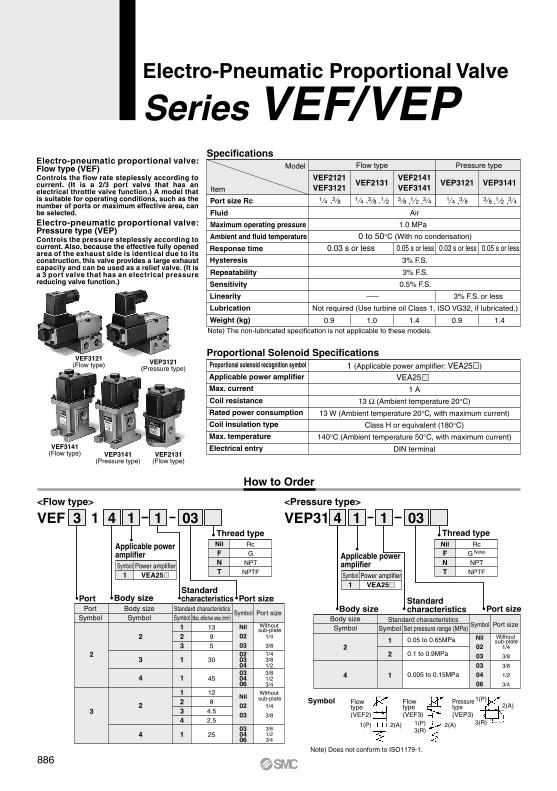
Specifications
Proportional Solenoid Specifications
Model Flow type Pressure type
Item
Air
3% F.S.
0.5% F.S.
3% F.S. or less
Not required (Use turbine oil Class 1, ISO VG32, if lubricated.)
3% F.S.
1.0 MPa
0 to 50°C (With no condensation)
VEF2121VEF3121
VEF2141VEF3141
VEF2131 VEP3121 VEP3141
0.03 s or less 0.03 s or less 0.05 s or less
,
0.9Note) The non-lubricated specification is not applicable to these models.
0.91.0 1.41.4
41 83 , 41 83, 41 , 83 21 83 , 21 43 , 83 , 21 43
030406
253/81/23/4
03<Pressure type>
4 1 1VEP31
1
2
14
2Nil
0203
1/4
3/8
030406
3/8
1/2
3/4
Standard characteristicsSet pressure range (MPa)
0.05 to 0.65MPa
0.1 to 0.9MPa
0.005 to 0.15MPa
Symbol1
,
VEF3121(Flow type)
VEP3141(Pressure type)
VEF2131(Flow type)
VEP3121(Pressure type)
VEF3141(Flow type)
NilFNT
RcG
NPTNPTF
NilFNT
RcG Note)
NPTNPTF
How to Order
Electro-pneumatic proportional valve: Flow type (VEF)Controls the flow rate steplessly according to current. (It is a 2/3 port valve that has an electrical throttle valve function.) A model that is suitable for operating conditions, such as the number of ports or maximum effective area, can be selected. Electro-pneumatic proportional valve: Pressure type (VEP)Controls the pressure steplessly according to current. Also, because the effective fully opened area of the exhaust side is identical due to its construction, this valve provides a large exhaust capacity and can be used as a relief valve. (It is a 3 port valve that has an electrical pressure reducing valve function.)
Port size Rc
Fluid
Maximum operating pressure
Hysteresis
Sensitivity
Linearity
Lubrication
Weight (kg)
Ambient and fluid temperature
Response time
Repeatability
Max. current
Rated power consumption
Coil insulation type
Max. temperature
Electrical entry
Proportional solenoid recognition symbol
Applicable power amplifier
Coil resistance
VEA25 1 A
1 (Applicable power amplifier: VEA25 )
13 Ω (Ambient temperature 20°C)
Class H or equivalent (180°C)
DIN terminal
13 W (Ambient temperature 20°C, with maximum current)
140°C (Ambient temperature 50°C, with maximum current)
Body sizeBody size Standard
characteristics
Standard characteristics
Port sizePort size
Applicable power amplifierSymbol
1
Applicable power amplifier
Thread typeThread type
PortPort
SymbolBody sizeSymbol Body size
Symbol
Standard characteristicsMax. effective area (mm2)
Port sizeSymbol
Port sizeSymbolSymbol
Symbol
886
Poweramplifier Control circuit
Electro-pneumaticproportional valve
(Pressure control valve)
Regulator valve (VEX1)
Pressurizingcylinder
Electrode
Check valve
Power amplifierwith feedback circuit
Control circuit
Pressure sensor
Cooler Regulator valve VEX1
Low pressure die-casting
Release valve
VEXP3141Electro-pneumatic proportional valve
Number ofrotationsFeedback
Tachometer
Air motor
Power amplifier(Feedback circuit built-in type)
Controlcircuit
Electro-pneumaticproportional valve(Flow type, 2 port)
VE 0 must be used in conjunction with the power amplifier VEA1 .The previous VE 0 cannot be used in combination with the current VEA25 , and the current VE 1 cannot be used in combin-ation with the previous VEA1 .
VEA10,VEPF
Be sure to read before handling.Refer to front matter 43 for Safety Instructions and pages 365 to 369 for Precautions on every series.
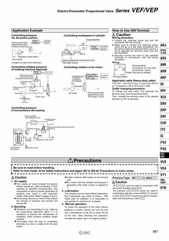
Controlling welding pressure of welding machine electrode
Controlling rotation of air motor
Controlling pressure of low pressure die-casting
Controlcircuit
PoweramplifierElectro-pneumatic
proportional valve(Pressure control vlave)
Regulator valve (VEX1)Die cushion
(Imagine air type shock absorber)
How to Use DIN Terminal
Wiring procedure
WiringTerminal blockConnection 3 is not usedfor terminal 1 and 2.
Note) Coil has no polarity.
Caution1. Loosen the retaining screw and pull the
connector from the pin plug. 2. Make sure to remove the retaining screw,
insert the tip of a flat head screwdriver into the groove below the terminal block and pry it up to separate the terminal cover from the terminal block.
3. Securely connect the wires to the specified terminals in accordance with the wiring procedure.
Applicable cable (Heavy-duty cable)0.75 mm2, 1.25 mm2/2 core, 3 core (O.D. ø6.8 to ø11.5) based on JIS C 3312 and C 3322Outlet changing procedureTo change the wire outlet, first separate the terminal cover from the terminal block.Then, reinstall the terminal cover in the desired direction (in 90° increments).
Pin plug shape
Precautions
Caution1. Air supply
Poor quality air could increase the spool’s sliding resistance, while preventing it from attaining its specified characteristics. Use compressor oil with a minimal generation of oxidants and install a mist separator (SMC’s AM series). Refer to pages 2 and 3.
Avoid using ultra-dry air since it may reduce the amount of lubricant and shorten the service life.
2. Mounting Vibrations are transmitted to the valve by
the proportional solenoid’s dither. If it is necessary to prevent the transmission of vibrations, insert vibration isolating rubber material. Thoroughly flush the pipe to completely eliminate any dust or scales from the pipe inside.
Install a silencer (AN series) on the exhaust port.Be careful with the molded coil because it generates heat while current is applied to it.
3. LubricationThis product can be used without lubrication. But if lubricated, use turbin oil Class 1, ISO VG32 (with no additive). It is impossible to use spindle oil, machine oil, or grease.
4. Manual operationTo check the operation of the valve without applying a current, remove the lock nut and use a screwdriver or the like to press the tip of the core. After checking the operation, reinstall the rubber cap in its original position.
Previous Type
Caution
PF
PF
PF
Application ExampleControlling pressure for die press cushion
Controlling multispeed of cylinder
Surge absorber
Electro-pneumatic proportional valveFlow type (3 port)
Poweramplifier
Controlcircuit
Series VEF/VEPElectro-Pneumatic Proportional Valve
887
ARJAR425to 935
ARX
AMR
ARM
ARP
IR
IRV
VEX
SRH
SRP
SRF
VCHR
ITV
IC
ITVX
PVQVEFVEP
VER
VEA
VY1VBAVBAT
AP100
VEFVEP
1 (P) 2 (A) 3 (R)
1 (P) 2 (A) 3 (R)
1 (P)2 (A)
1(P) 2
(A) c
ontrol
1(P)
2(A
) con
trol
3 port
Current
2 port
2(A)
3
(R) c
ontro
l
Flo
w r
ate
Closed
Fully open
Fully open
Note)
F1 solenoid F2 spring
Controlled opening
Sleeve
Spool
3 (R)
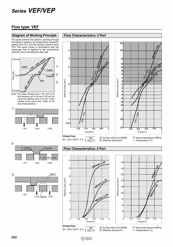
Q: Air flow rate [L/mi (ANR)] P: Valve-inlet pressure [MPa]S : Effective area [mm2] t : Temperature [°C]
293————273 + t
Q = 120 x S (P + 0.1)
Q: Air flow rate [L/mi (ANR)] P: Valve-inlet pressure [MPa]S : Effective area [mm2] t : Temperature [°C]
Choked flow
Choked flow
293————273 + t
Q = 120 x S (P + 0.1)
Series VEF/VEP
Flow type: VEF
Note) The areas between port 1 (P) and 2 (A) and between port 2 (A) and 3 (R) will not equal the effective area of 0 mm2 (valve closed) at the same time. (Refer to the flow characteristics.)
Diagram of Working Principle Flow Characteristics: 3 Port
Flow Characteristics: 2 Port
Effe
ctiv
e ar
ea (
mm
2 )
Effe
ctiv
e ar
ea (
mm
2 )E
ffect
ive
area
(m
m2 )
Effe
ctiv
e ar
ea (
mm
2 )
Current A Current A
Current A Current A
The spool controls the sleeve’s opening through the balance between the proportional solenoid’s pulling force (F1) and the spring’s reaction force (F2). The spool moves in accordance with the amperage that is applied to the proportional solenoid, thus controlling the flow rate.
888
Spool
Sleeve
F1 solenoid
Feedback passage
(Inlet pressure) (Outlet pressure)
Set point
Set point
Set point
Out
let p
ress
ure
(MP
a)O
utle
t pre
ssur
e (M
Pa)
Out
let p
ress
ure
(MP
a)
Out
let p
ress
ure
(MP
a)O
utle
t pre
ssur
e (M
Pa)
Out
let p
ress
ure
(MP
a)O
utle
t pre
ssur
e (M
Pa)
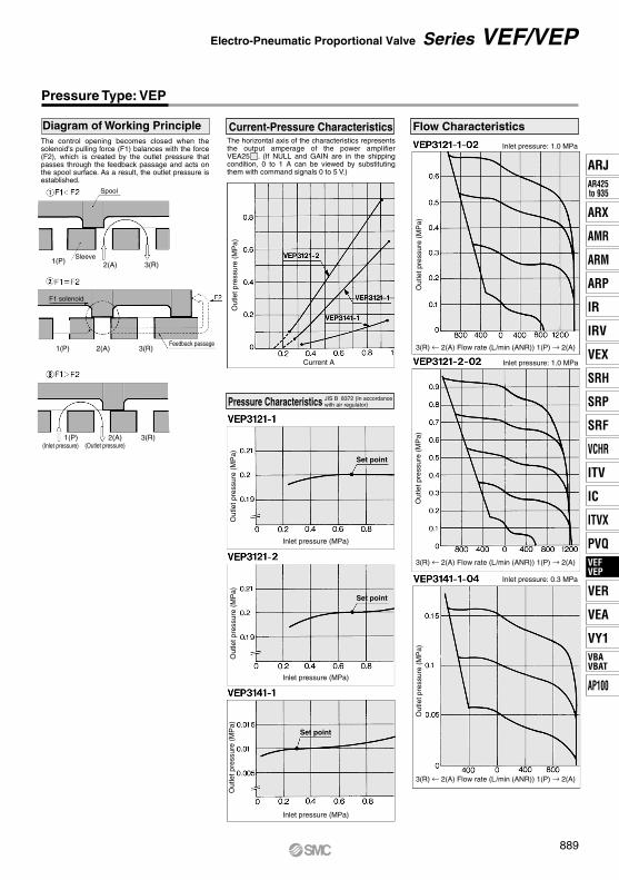
Inlet pressure: 1.0 MPa
Inlet pressure: 1.0 MPa
Inlet pressure: 0.3 MPa
Pressure Type: VEP
1(P) 2(A) 3(R)
1(P) 2(A) 3(R)
1(P) 2(A) 3(R)
Flow Characteristics
3(R) ← 2(A) Flow rate (L/min (ANR)) 1(P) → 2(A)
3(R) ← 2(A) Flow rate (L/min (ANR)) 1(P) → 2(A)
3(R) ← 2(A) Flow rate (L/min (ANR)) 1(P) → 2(A)
Inlet pressure (MPa)
Inlet pressure (MPa)
Inlet pressure (MPa)
Current A
Pressure Characteristics JIS B 8372 (In accordance with air regulator)
Current-Pressure CharacteristicsThe horizontal axis of the characteristics represents the output amperage of the power amplifier VEA2555. (If NULL and GAIN are in the shipping condition, 0 to 1 A can be viewed by substituting them with command signals 0 to 5 V.)
Diagram of Working PrincipleThe control opening becomes closed when the solenoid's pulling force (F1) balances with the force (F2), which is created by the outlet pressure that passes through the feedback passage and acts on the spool surface. As a result, the outlet pressure is established.
Series VEF/VEPElectro-Pneumatic Proportional Valve
889
ARJAR425to 935
ARX
AMR
ARM
ARP
IR
IRV
VEX
SRH
SRP
SRF
VCHR
ITV
IC
ITVX
PVQVEFVEP
VER
VEA
VY1VBAVBAT
AP100
VEFVEP
Port1 (P)
Port3 (R)
Port 1 (P)
Port1 (P)
Port 3 (R)
Port 2 (A)
Port 2 (A)
Note) Does not conform to ISO1179-1.
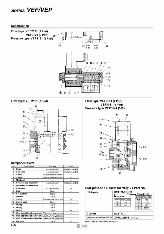
Construction
Sub-plate and Gasket for VE 121 Part No.wSub-plate
Thread typePort size
!1Gasket DXT172-7
!7Hex. socket head cap screw (With SW) XT012-25D-1 (M4 x 32)
NilFNT
Thread typeRc
G Note)
NPTNPTF
Symbol
12
Port size1/43/8
Symbol
No. Description NoteMaterial
Metallic paintedMetallic painted
———
Metallic painted——————————————
Aluminum alloyAluminum alloy
Special stainless steelSpecial stainless steel
—Aluminum alloy
—Aluminum alloy
ResinBrassNBR
Stainless steel/Piano wireBrassNBRNBRNBR
Chromium-molybdenumChromium-molybdenumChromium-molybdenum
NBR
BodySub-plateSpoolSleeveMold coilSolenoid cap assemblyMovable core assemblyEnd coverBushSet bushingGasketSpringSpring seatO-ringO-ringO-ringHex. socket head cap screwHex. socket head cap screwHex. socket head cap screwLock nut
1234567891011121314151617181920
Component Parts
Flow type: VEF2121 (2 Port) VEF3121 (3 Port)Pressure type: VEP3121 (3 Port)
Flow type: VEF2131 (2 Port) Flow type: VEF2141 (2 Port) VEF3141 (3 Port)Pressure type: VEP3141 (3 Port)
F2P3
Series VEF/VEP
890

A
RP
Port1 (P)Port
2(A) Port2 (A)
Port3 (R)
Port1 (P)
R
P
P
A
Port3 (R)
Port1 (P)
88
40Port 2 (A)
3 x ø5.5Mounting hole
45
2 port: Port 3 (R) plug
6456G1/2
Applicable cable O.D.ø6 to ø12
28
13
25
50
122 3 x1/4, 3/8
112.
2
99.7
21.5
45
129
95
65
64
35
G1/2Applicable cable O.D.ø6 to ø12
51
64
9
Plug
2 x1/4, 3/8, 1/2
50
50
88.7
101.
2
3 x ø7Mounting hole
45
53
82
2 port: Port 3 (R) plug
154.
5
120.
5
105.
9
93.4
66
52
4 x ø9Mounting hole
G1/2
Applicable cable O.D.ø6 to ø12
3 x3/8, 1/2, 3/4
3635
12
81
Dimensions
Series VEF/VEPElectro-Pneumatic Proportional Valve
Flow type: VEF2121, VEF3121Pressure type: VEP3121
Flow type: VEF2131 Flow type: VEF2141, VEF3141Pressure type: VEP3141
891
ARJAR425to 935
ARX
AMR
ARM
ARP
IR
IRV
VEX
SRH
SRP
SRF
VCHR
ITV
IC
ITVX
PVQVEFVEP
VER
VEA
VY1VBAVBAT
AP100
VEFVEP
A