
Optimal Design of Battery-Ultracapacitor Hybrid Source Light/Heavy Electrified Vehicle

1© 2015 The MathWorks, Inc.
Electrified Powertrain Vehicle
Simulation in Simulink
Wit Nursilo Ph.D.Application Engineer, MathWorks USA

2
Models Understanding==
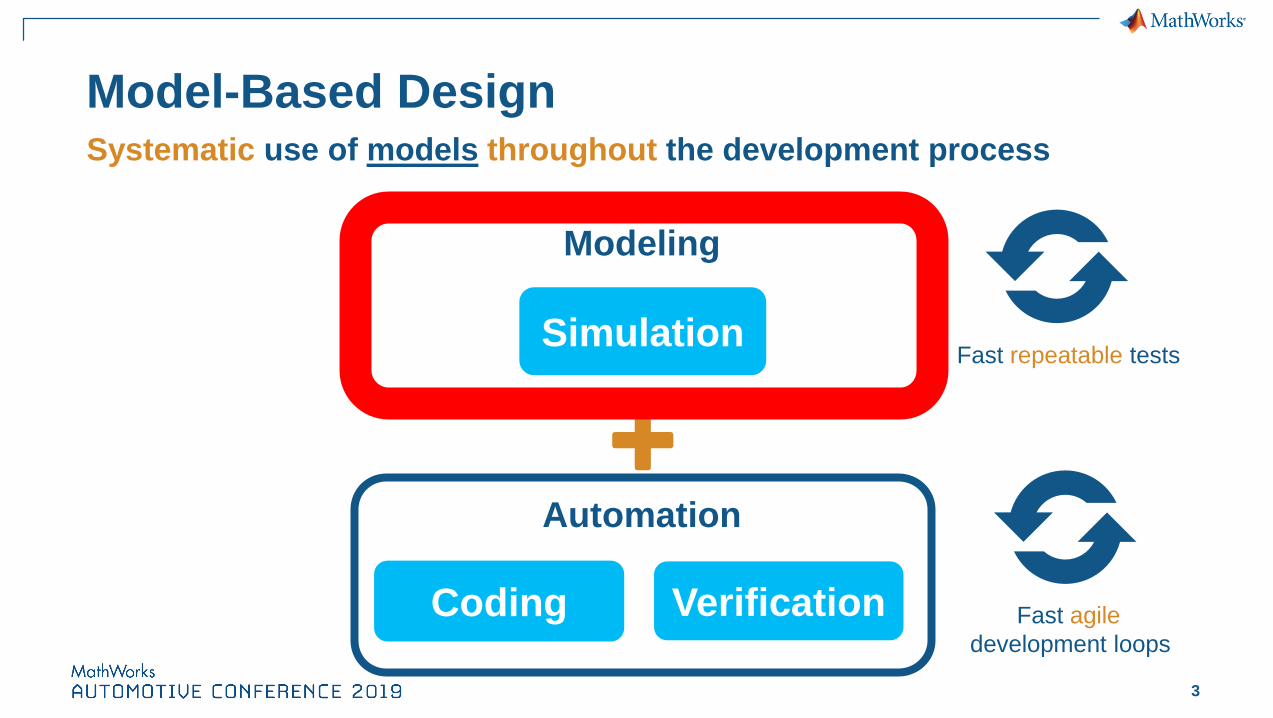
3
Simulation
Coding Verification
Modeling
Automation
Model-Based Design Systematic use of models throughout the development process
Fast repeatable tests
Fast agile
development loops

4
Electric Vehicle Example
▪ 3-Motors Architecture
– Rear : 2 x 40kW Motor
– Front: 60kW Motor
– 50kW-hr battery
▪ Torque Vectoring Capability
– Independent dual motors
▪ Use Model-Based Design to
– Assess performance
– Develop control algorithms
– Visualize and test
– Deploy to hardware
Rear Right Wheel & Brake
Rear Left Wheel & BrakeFront Left Wheel & Brake
Front Right Wheel & Brake
Motor
Motor
Motor
Battery
Differential

5
Model Use Cases Across the V-cycle
Subsystem Design
EV Design Exploration/Component Sizing
PIL Testing
Drivability Validation
Control Design
HIL Testing
6
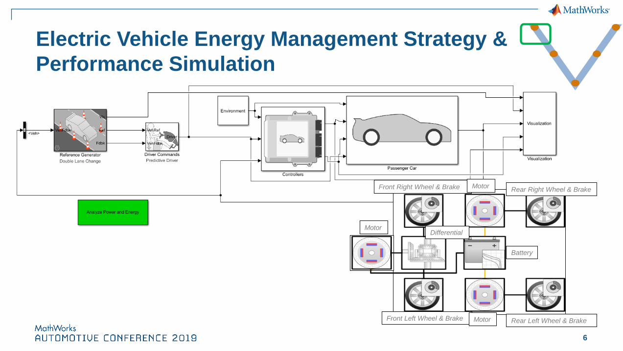
Electric Vehicle Energy Management Strategy &
Performance Simulation
Rear Right Wheel & Brake
Rear Left Wheel & BrakeFront Left Wheel & Brake
Front Right Wheel & Brake
Motor
Motor
Motor
Battery
Differential
7
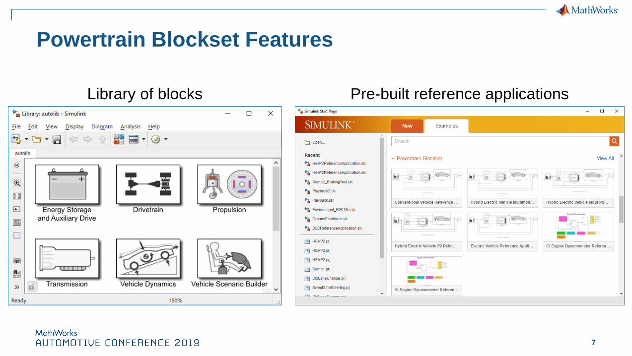
Powertrain Blockset Features
Library of blocks Pre-built reference applications

8
Rear Right Wheel & Brake
Rear Left Wheel & BrakeFront Left Wheel & Brake
Front Right Wheel & Brake
Motor
Motor
Motor
Battery
Differential
Tdemand = Tmot,f + Tmot,r
EV Energy Management Strategy (EMS)
▪ Instantaneous torque (or power)
command to actuators (electric
machines)
▪ Subject to constraints:
▪ Attempt to minimize energy
consumption, maintain drivability
𝜏𝑚𝑖𝑛 𝜔 ≤ 𝜏𝑎𝑐𝑡 ≤ 𝜏𝑚𝑎𝑥 𝜔𝑃𝑐ℎ𝑔 𝑆𝑂𝐶 ≤ 𝑃𝑏𝑎𝑡𝑡 ≤ 𝑃𝑑𝑖𝑠𝑐ℎ𝑔 𝑆𝑂𝐶
𝐼𝑐ℎ𝑔 𝑆𝑂𝐶 ≤ 𝐼𝑏𝑎𝑡𝑡 ≤ 𝐼𝑑𝑖𝑠𝑐ℎ𝑔 𝑆𝑂𝐶

9
EV Energy Management Strategy (EMS) Process
1. Create torque
split vector
2. Check constraints,
determine
infeasible conditions
3. Calculate and
minimize cost
function(Battery Power)
−𝑀𝑖𝑛 𝑅𝑒𝑎𝑟 𝑇𝑜𝑟𝑞𝑢𝑒⋮
+𝑀𝑎𝑥 𝑅𝑒𝑎𝑟 𝑇𝑜𝑟𝑞𝑢𝑒
min𝜏𝑟𝑒𝑎𝑟
𝑃𝑏 𝜏𝑟𝑒𝑎𝑟𝜏𝑚𝑖𝑛 𝜔 ≤ 𝜏𝑎𝑐𝑡 ≤ 𝜏𝑚𝑎𝑥 𝜔𝑃𝑐ℎ𝑔 𝑆𝑂𝐶 ≤ 𝑃𝑏𝑎𝑡𝑡 ≤ 𝑃𝑑𝑖𝑠𝑐ℎ𝑔 𝑆𝑂𝐶
𝐼𝑐ℎ𝑔 𝑆𝑂𝐶 ≤ 𝐼𝑏𝑎𝑡𝑡 ≤ 𝐼𝑑𝑖𝑠𝑐ℎ𝑔 𝑆𝑂𝐶
𝜏𝑑𝑒𝑚𝑎𝑛𝑑 = 𝜏𝑓𝑟𝑜𝑛𝑡 + 𝜏𝑟𝑒𝑎𝑟

10
EV Energy Management Strategy (EMS) ProcessInfeasible
Regions
11
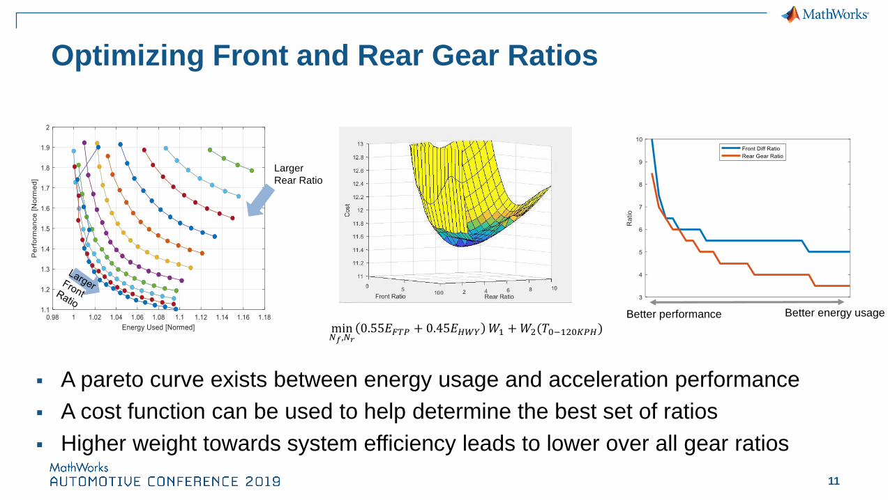
Optimizing Front and Rear Gear Ratios
Larger
Rear Ratio
Better energy usageBetter performance
min𝑁𝑓,𝑁𝑟
0.55𝐸𝐹𝑇𝑃 + 0.45𝐸𝐻𝑊𝑌 𝑊1 +𝑊2(𝑇0−120𝐾𝑃𝐻)
▪ A pareto curve exists between energy usage and acceleration performance
▪ A cost function can be used to help determine the best set of ratios
▪ Higher weight towards system efficiency leads to lower over all gear ratios

12
Electric Vehicle Torque Vectoring Simulation
▪ 6-DOF Vehicle
▪ 2-DOF Tire + Brake
▪ Suspension
▪ Steering
14-DOF

13
Vehicle Dynamics Blockset Features
Game engine
Pre-built Reference
Applications
Library of Blocks

16
Vehicle Dynamics Control – Torque Vectoring
Average Steer Angle
Tire Slip Angle =𝑎+𝑏 𝑟
ሶ𝑥TV Torque
Greater lateral acceleration with 8.7% less steering input
Longer linear tire slip angle region and 5.7% greater lateral acceleration
𝑎
𝑏
ሶ𝑥
𝑟

17
Vehicle Dynamics Control – Torque Vectoring
Steering = 45o Right
WOT
Red = TV On
Blue = TV Off
TV On
TV Off

18
Vehicle Model Simulation – Driver-in-the-Loop

19
Subsystem & Components Modeling-- Motor / Motor Control
Different Fidelity of Motor Modeling:
▪ Map Based
▪ Detail Model (Inverter controller + nonlinear
motor model)
▪ High Fidelity Model
• FEA simulations
• or dyno data used to obtain flux table

20
Subsystem & Components Modeling-- Battery / BMS
Exponential relaxation
Instantaneous response
VΩ
Vo
lta
ge
time
Open circuit potential
emf (V)R0 (Ω)
R1 (Ω)
C1 (F)
5ºC20ºC40ºC
R1
C1
R0
emf
SoCSoC
R0
R1
C1Em

21
Subsystem & Components Modeling-- Cooling System (Battery/Electrical)
▪ Multi-physics model:
Moist Air – 2-Phase Fluid – Thermal Liquid
▪ Thermal management algorithm design, power
consumption estimate & component sizing
p-h diagram
for design &
diagnostics
Auxiliary Power

23
Control Feature Testing and Validation-- One-Pedal Control
Regen Braking
Coasting Acceleration
0% APP
100% APP
35MPH→30MPH
▪ One Pedal algorithm allows for braking behavior with only pedal actuation
▪ Zone calibration effects drivability behavior and “Fun To Drive” characteristics

24
Processor –in-the-Loop (PIL) SimulationNXP + MathWorks Collaboration Demo

25
Processor –in-the-Loop (PIL) Simulation
NXP + MathWorks Collaboration Demo

26
Hardware-in-the-Loop (HIL) Simulation
CAN CableSpeedgoat Rapid Control
Prototyping System Embedded Controller HardwareTarget Computer Hardware
Speedgoat Hardware
in-the-loop System

27
Summary
Subsystem Design
EV Design Exploration/Component Sizing
PIL Testing
Drivability Validation
Control Design
HIL Testing

28
Key Takeaways
Use Simulink based virtual vehicle capabilities to:
– Quantify tradeoffs between vehicle
performance characteristics
– Develop and verify control features
– Verify detail components behavior
and their affects in vehicle system
– PIL/HIL tests


