Electrical Performance, Reliability Analysis, and ...Electrical Performance, Reliability Analysis,...
25
ORNL is managed by UT-Battelle for the US Department of Energy Electrical Performance, Reliability Analysis, and Characterization Tim Burress Email: [email protected] Phone: 865-946-1216 This presentation does not contain any proprietary, confidential, or otherwise restricted information 2017 U.S. DOE Vehicle Technologies Office Annual Merit Review Oak Ridge National Laboratory National Transportation Research Center June 6, 2017 Project ID: EDT087
Transcript of Electrical Performance, Reliability Analysis, and ...Electrical Performance, Reliability Analysis,...

ORNL is managed by UT-Battelle for the US Department of Energy
Electrical Performance, Reliability Analysis, and Characterization
Tim BurressEmail: [email protected]: 865-946-1216
This presentation does not contain any proprietary, confidential, or otherwise restricted information
2017 U.S. DOE Vehicle Technologies Office Annual Merit Review
Oak Ridge National LaboratoryNational Transportation Research Center
June 6, 2017 Project ID: EDT087
2 2017 VTO AMR Peer Evaluation Meeting
Overview
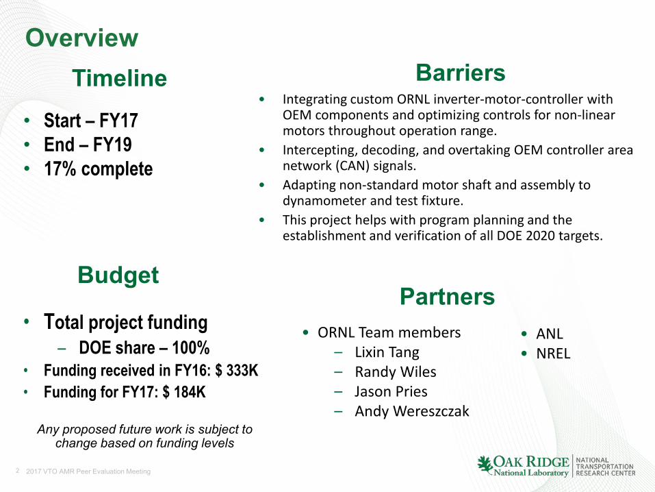
• Start – FY17• End – FY19• 17% complete
• Integrating custom ORNL inverter-motor-controller with OEM components and optimizing controls for non-linear motors throughout operation range.
• Intercepting, decoding, and overtaking OEM controller area network (CAN) signals.
• Adapting non-standard motor shaft and assembly to dynamometer and test fixture.
• This project helps with program planning and the establishment and verification of all DOE 2020 targets.
• Total project funding– DOE share – 100%
• Funding received in FY16: $ 333K• Funding for FY17: $ 184K
Timeline
Budget
Barriers
Partners
Any proposed future work is subject to change based on funding levels
• ANL• NREL
• ORNL Team members– Lixin Tang– Randy Wiles– Jason Pries– Andy Wereszczak
3 2017 VTO AMR Peer Evaluation Meeting
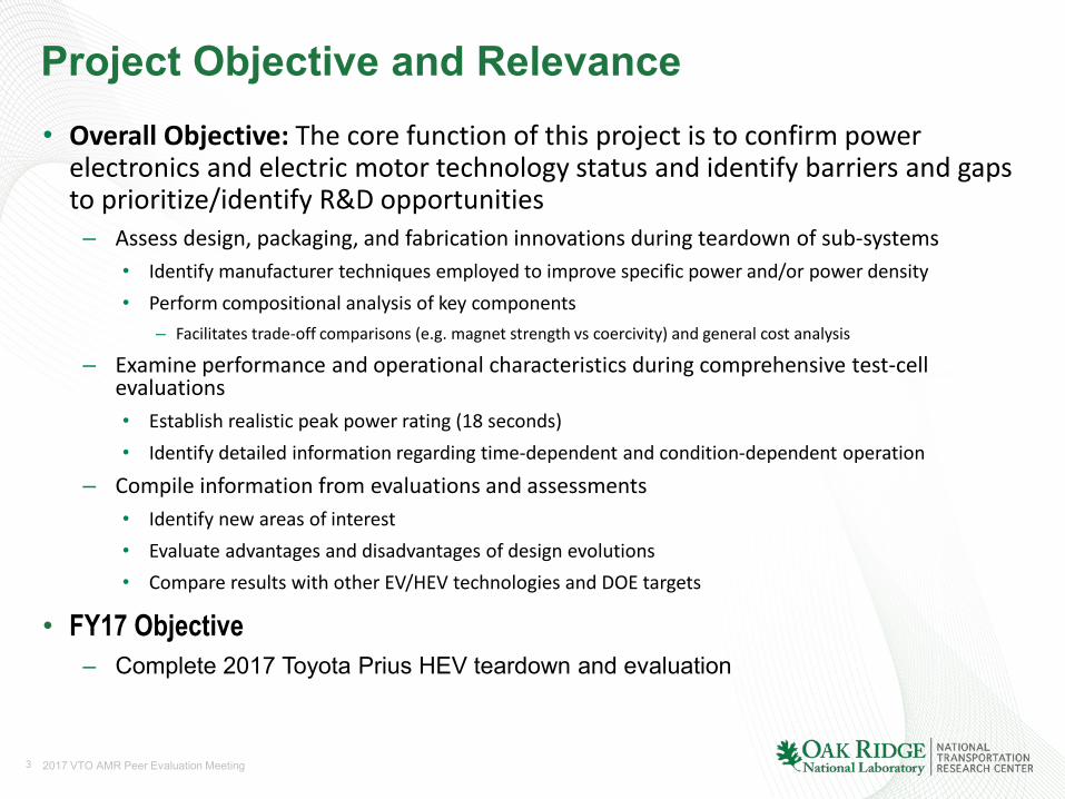
Project Objective and Relevance• Overall Objective: The core function of this project is to confirm power
electronics and electric motor technology status and identify barriers and gaps to prioritize/identify R&D opportunities
– Assess design, packaging, and fabrication innovations during teardown of sub-systems• Identify manufacturer techniques employed to improve specific power and/or power density• Perform compositional analysis of key components
– Facilitates trade-off comparisons (e.g. magnet strength vs coercivity) and general cost analysis
– Examine performance and operational characteristics during comprehensive test-cell evaluations• Establish realistic peak power rating (18 seconds)• Identify detailed information regarding time-dependent and condition-dependent operation
– Compile information from evaluations and assessments• Identify new areas of interest• Evaluate advantages and disadvantages of design evolutions• Compare results with other EV/HEV technologies and DOE targets
• FY17 Objective – Complete 2017 Toyota Prius HEV teardown and evaluation
4 2017 VTO AMR Peer Evaluation Meeting
Milestones
Any proposed future work is subject to change based on funding levels
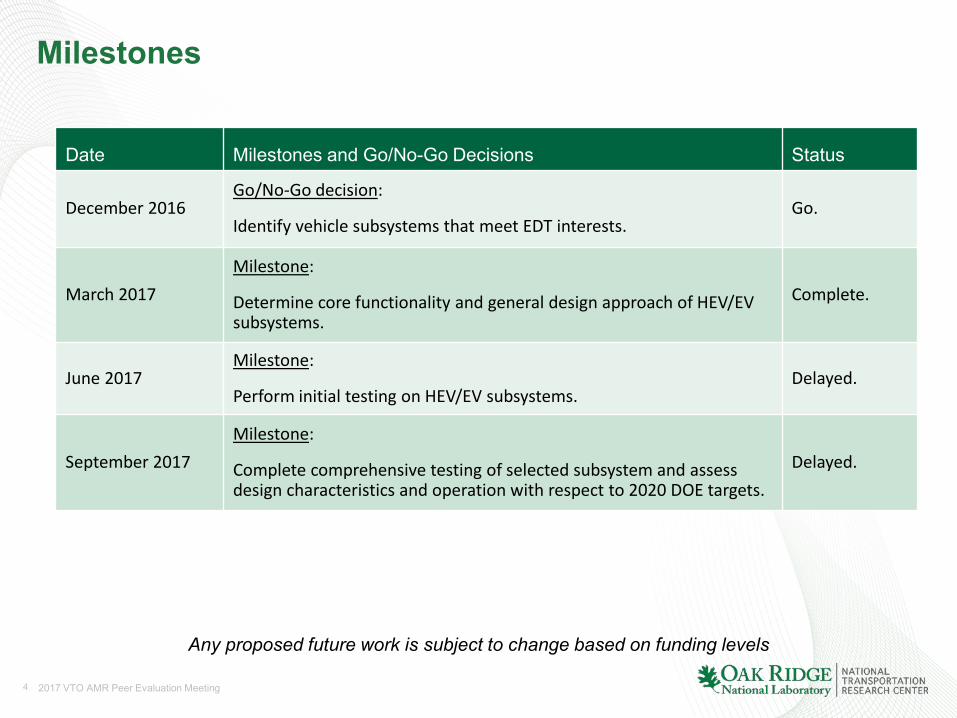
Date Milestones and Go/No-Go Decisions Status
December 2016Go/No-Go decision:
Identify vehicle subsystems that meet EDT interests.Go.
March 2017Milestone:
Determine core functionality and general design approach of HEV/EV subsystems.
Complete.
June 2017Milestone:
Perform initial testing on HEV/EV subsystems.Delayed.
September 2017Milestone:
Complete comprehensive testing of selected subsystem and assess design characteristics and operation with respect to 2020 DOE targets.
Delayed.
5 2017 VTO AMR Peer Evaluation Meeting
Approach/Strategy
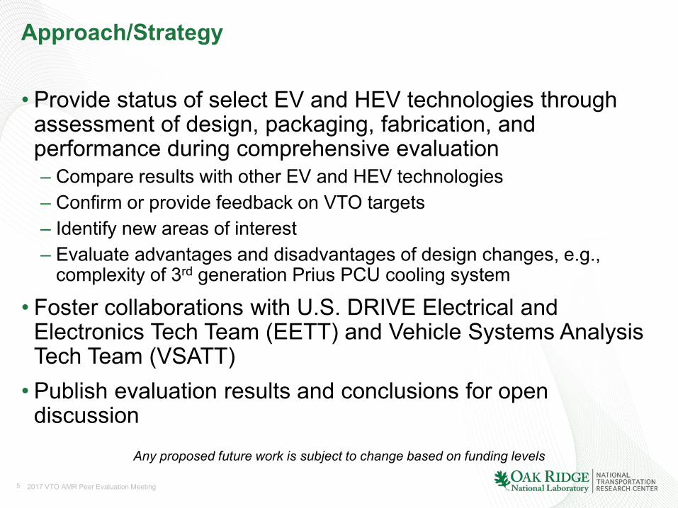
• Provide status of select EV and HEV technologies through assessment of design, packaging, fabrication, and performance during comprehensive evaluation– Compare results with other EV and HEV technologies– Confirm or provide feedback on VTO targets– Identify new areas of interest– Evaluate advantages and disadvantages of design changes, e.g.,
complexity of 3rd generation Prius PCU cooling system
• Foster collaborations with U.S. DRIVE Electrical and Electronics Tech Team (EETT) and Vehicle Systems Analysis Tech Team (VSATT)• Publish evaluation results and conclusions for open
discussion
Any proposed future work is subject to change based on funding levels
6 2017 VTO AMR Peer Evaluation Meeting
Approach/Strategy
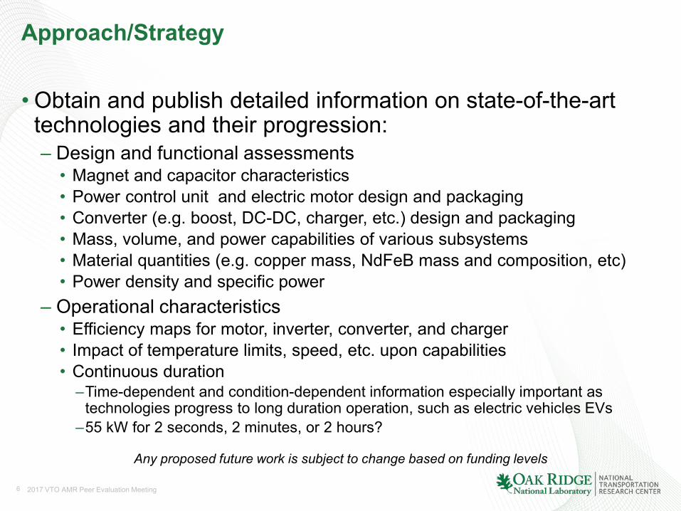
•Obtain and publish detailed information on state-of-the-art technologies and their progression:– Design and functional assessments• Magnet and capacitor characteristics• Power control unit and electric motor design and packaging• Converter (e.g. boost, DC-DC, charger, etc.) design and packaging• Mass, volume, and power capabilities of various subsystems • Material quantities (e.g. copper mass, NdFeB mass and composition, etc)• Power density and specific power
– Operational characteristics• Efficiency maps for motor, inverter, converter, and charger• Impact of temperature limits, speed, etc. upon capabilities• Continuous duration
–Time-dependent and condition-dependent information especially important as technologies progress to long duration operation, such as electric vehicles EVs
–55 kW for 2 seconds, 2 minutes, or 2 hours?
Any proposed future work is subject to change based on funding levels
7 2017 VTO AMR Peer Evaluation Meeting
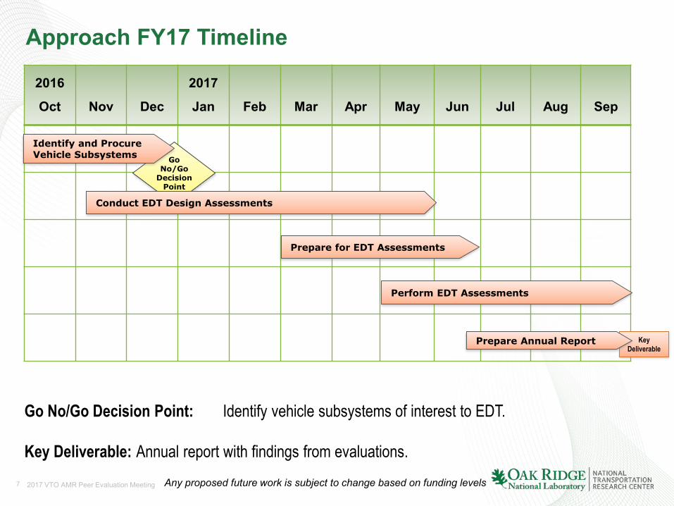
Approach FY17 Timeline
2016
Oct Nov Dec
2017
Jan Feb Mar Apr May Jun Jul Aug Sep
Go No/Go Decision Point: Identify vehicle subsystems of interest to EDT.
Key Deliverable: Annual report with findings from evaluations.
Key Deliverable
Any proposed future work is subject to change based on funding levels
Go No/Go
Decision Point
Identify and Procure Vehicle Subsystems
Conduct EDT Design Assessments
Prepare for EDT Assessments
Perform EDT Assessments
Prepare Annual Report

8 2017 VTO AMR Peer Evaluation Meeting
Technical Accomplishments – Previous FYs
• Compared progressing technologies - 2004 Prius, 2006 Accord, 2007 Camry, 2008 LS 600h, 2010 Prius, 2011 Sonata, 2012 Sonata generator, 2012 LEAF, 2013 LEAF charger, 2013 Camry PCU, 2014 Accord, 2016 BMW i3, and 2017 Prius.
Note: All power density and specific power levels in table are not apples-to-apples. (e.g. LEAF and Sonata have continuous capability near their published rated power)
2022 DOE Targets (55 kW)
2017 Prius (53 kW)
2016 BMW i3 (125 kW)
2014 Honda Accord
(124 kW)
2012 Leaf (80 kW)
2012 Sonata
HSG 23 (8.5 kW)
2011 Sonata (30 kW)
2010 Prius
(60 kW)
2008 LS600h Lexus
(110 kW)
2007 Camry
(70 kW)
2013 Camry
(105 kW)
2004 Prius
(50 kW)
Peak pow er density, kW/L 5.7 5.7 9.1 8.5 4.2 7.42 (2.7) 3.0 4.8 6.6 5.9 3.3
Peak specif ic pow er, kW/kg 1.6 1.7 3.0 2.9 1.4 1.9 (0.7) 1.1 1.6 2.5 1.7 1.1
Peak pow er density, kW/L 13.4 11.5 (21.7) 18.5 12.1 (18.5) 5.7 5.6 (2.0) 7.3 5.9 (11.1) 10.6 (17.2) 7.4 (11.7) 12.7 (19.0) 4.5 (7.4)
Peak specif ic pow er, kW/kg 14.1 8.6 (19.0) 14.1 9.1 (21.7) 4.9 5.4 (2.0) 6.9 6.9 (16.7) 7.7 (14.9) 5.0 (9.3) 11.5 (17.2) 3.8 (6.2)
Component & Parameter
Inverter
Motor
Excludes generator inverter (parenthetical values exclude boost converter mass/volume for Toyota Vehicles)
9 2017 VTO AMR Peer Evaluation Meeting
C
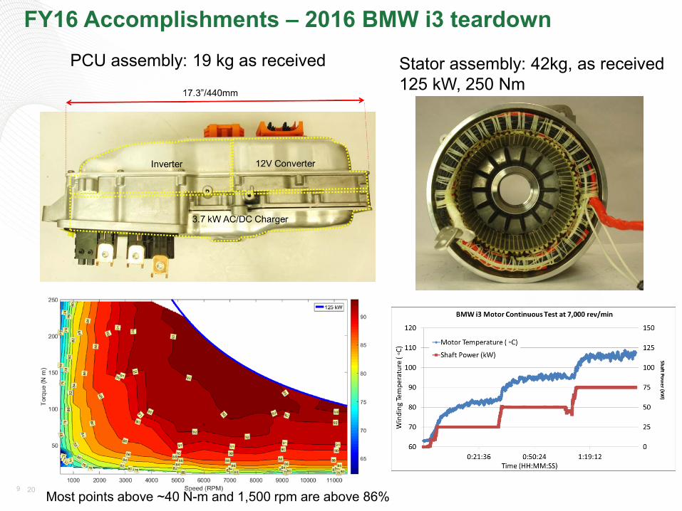
FY16 Accomplishments – 2016 BMW i3 teardown
Stator assembly: 42kg, as received125 kW, 250 Nm
PCU assembly: 19 kg as received
Most points above ~40 N-m and 1,500 rpm are above 86%
10 2017 VTO AMR Peer Evaluation Meeting
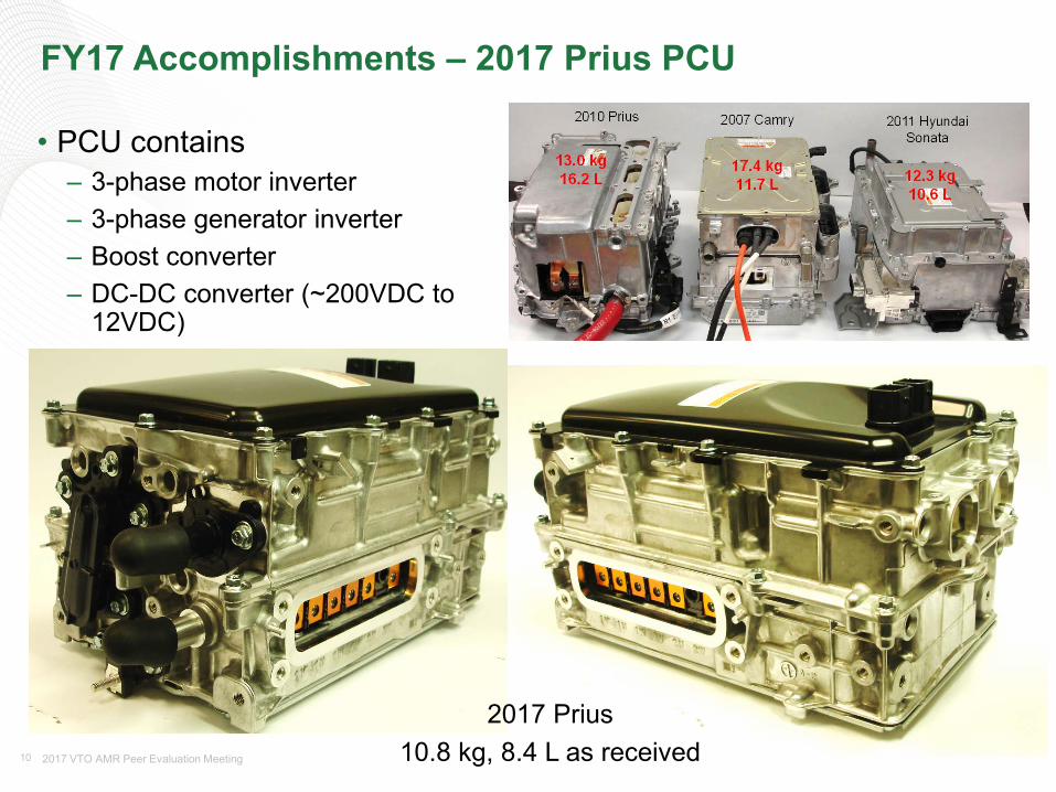
FY17 Accomplishments – 2017 Prius PCU
• PCU contains– 3-phase motor inverter– 3-phase generator inverter– Boost converter– DC-DC converter (~200VDC to
12VDC)
10.8 kg, 8.4 L as received2017 Prius

11 2017 VTO AMR Peer Evaluation Meeting
FY17 Accomplishments - 2017 Prius PCU
Middle CompartmentBottom compartment (12V converter)
Boost inductor (1.4 kg)
6 IGBT modules
471 μFhigh voltage
capacitor
Two cooling loops
Top Compartment
12 2017 VTO AMR Peer Evaluation Meeting
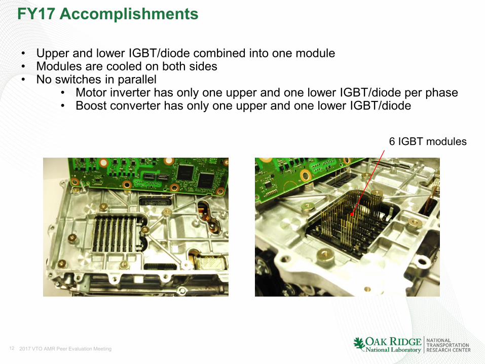
FY17 Accomplishments
• Upper and lower IGBT/diode combined into one module• Modules are cooled on both sides• No switches in parallel
• Motor inverter has only one upper and one lower IGBT/diode per phase• Boost converter has only one upper and one lower IGBT/diode
6 IGBT modules
13 2017 VTO AMR Peer Evaluation Meeting
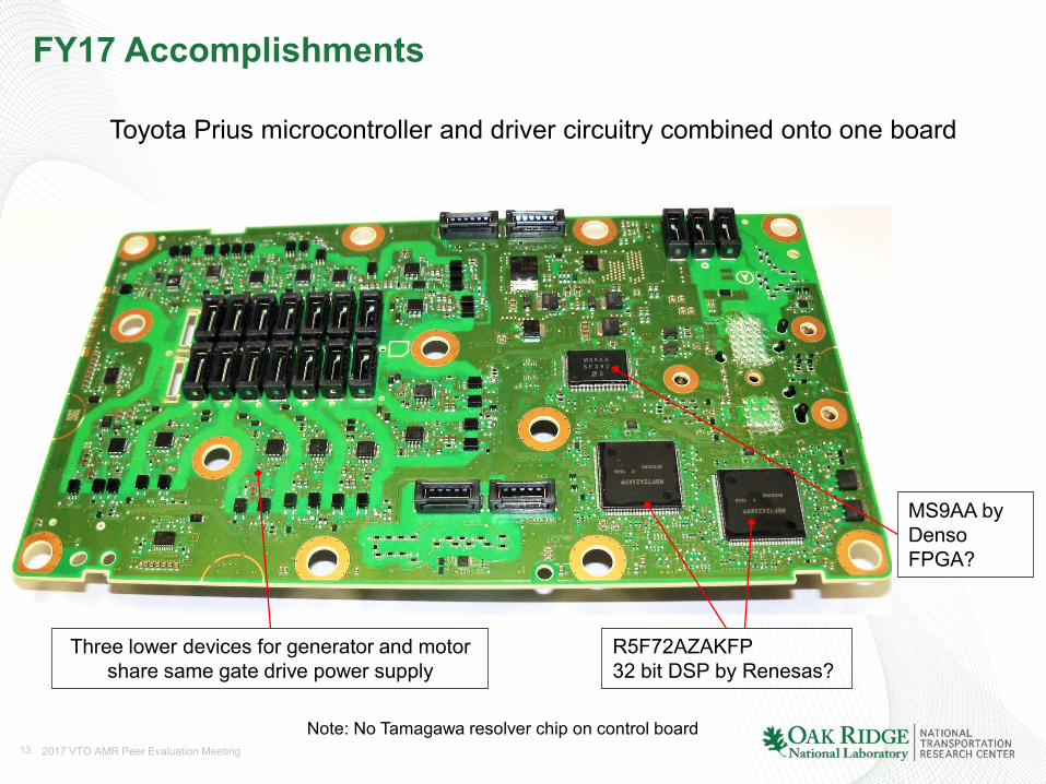
FY17 Accomplishments
R5F72AZAKFP32 bit DSP by Renesas?
MS9AA by DensoFPGA?
Note: No Tamagawa resolver chip on control board
Three lower devices for generator and motor share same gate drive power supply
Toyota Prius microcontroller and driver circuitry combined onto one board
14 2017 VTO AMR Peer Evaluation Meeting
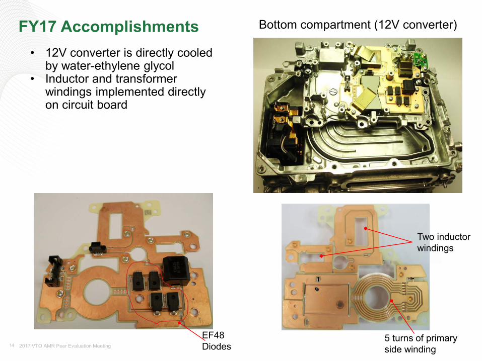
FY17 Accomplishments
EF48 Diodes
5 turns of primary side winding
Two inductor windings
Bottom compartment (12V converter)
• 12V converter is directly cooledby water-ethylene glycol
• Inductor and transformerwindings implemented directlyon circuit board
15 2017 VTO AMR Peer Evaluation Meeting
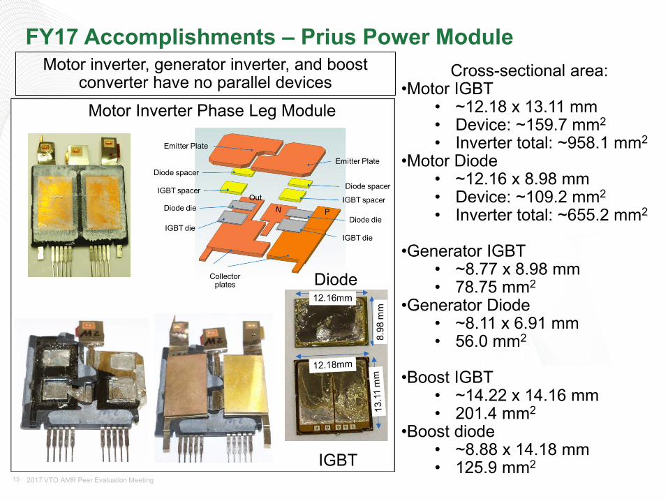
FY17 Accomplishments – Prius Power ModuleCross-sectional area:
•Motor IGBT• ~12.18 x 13.11 mm• Device: ~159.7 mm2
• Inverter total: ~958.1 mm2
•Motor Diode• ~12.16 x 8.98 mm• Device: ~109.2 mm2
• Inverter total: ~655.2 mm2
•Generator IGBT• ~8.77 x 8.98 mm• 78.75 mm2
•Generator Diode• ~8.11 x 6.91 mm• 56.0 mm2
•Boost IGBT• ~14.22 x 14.16 mm• 201.4 mm2
•Boost diode• ~8.88 x 14.18 mm• 125.9 mm2
Diode
IGBT
Motor inverter, generator inverter, and boost converter have no parallel devices
Motor Inverter Phase Leg Module
16 2017 VTO AMR Peer Evaluation Meeting
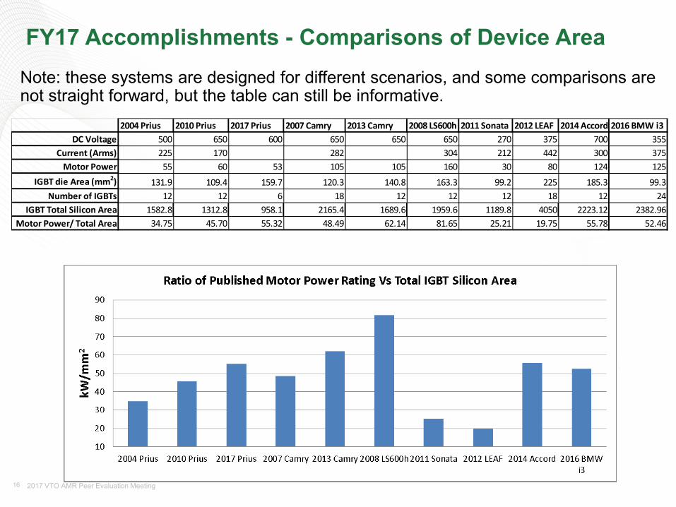
FY17 Accomplishments - Comparisons of Device Area Note: these systems are designed for different scenarios, and some comparisons are not straight forward, but the table can still be informative.
2004 Prius 2010 Prius 2017 Prius 2007 Camry 2013 Camry 2008 LS600h 2011 Sonata 2012 LEAF 2014 Accord 2016 BMW i3DC Voltage 500 650 600 650 650 650 270 375 700 355
Current (Arms) 225 170 282 304 212 442 300 375Motor Power 55 60 53 105 105 160 30 80 124 125
IGBT die Area (mm2) 131.9 109.4 159.7 120.3 140.8 163.3 99.2 225 185.3 99.3Number of IGBTs 12 12 6 18 12 12 12 18 12 24
IGBT Total Silicon Area 1582.8 1312.8 958.1 2165.4 1689.6 1959.6 1189.8 4050 2223.12 2382.96Motor Power/ Total Area 34.75 45.70 55.32 48.49 62.14 81.65 25.21 19.75 55.78 52.46
17 2017 VTO AMR Peer Evaluation Meeting
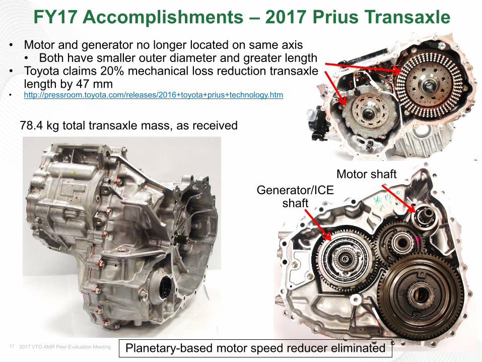
FY17 Accomplishments – 2017 Prius Transaxle• Motor and generator no longer located on same axis
• Both have smaller outer diameter and greater length• Toyota claims 20% mechanical loss reduction transaxle
length by 47 mm • http://pressroom.toyota.com/releases/2016+toyota+prius+technology.htm
78.4 kg total transaxle mass, as received
Motor shaftGenerator/ICE
shaft
Planetary-based motor speed reducer eliminated
18 2017 VTO AMR Peer Evaluation Meeting
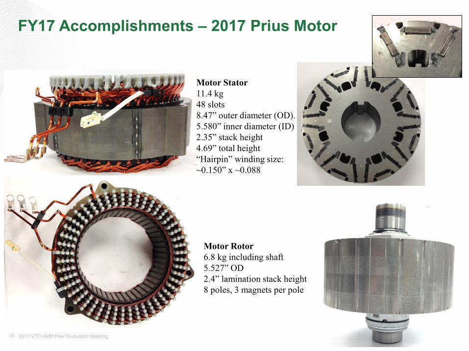
FY17 Accomplishments – 2017 Prius Motor
Motor Rotor6.8 kg including shaft5.527” OD2.4” lamination stack height8 poles, 3 magnets per pole
Motor Stator11.4 kg48 slots8.47” outer diameter (OD).5.580” inner diameter (ID)2.35” stack height 4.69” total height“Hairpin” winding size:~0.150” x ~0.088
19 2017 VTO AMR Peer Evaluation Meeting
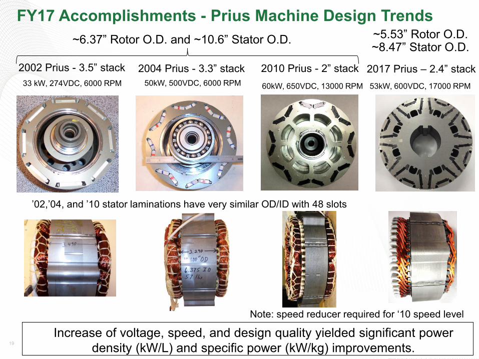
FY17 Accomplishments - Prius Machine Design Trends
Increase of voltage, speed, and design quality yielded significant power density (kW/L) and specific power (kW/kg) improvements.
2002 Prius - 3.5” stack 2004 Prius - 3.3” stack 2010 Prius - 2” stack50kW, 500VDC, 6000 RPM 60kW, 650VDC, 13000 RPM33 kW, 274VDC, 6000 RPM
’02,’04, and ’10 stator laminations have very similar OD/ID with 48 slots
Note: speed reducer required for ‘10 speed level
~6.37” Rotor O.D. and ~10.6” Stator O.D.
53kW, 600VDC, 17000 RPM
2017 Prius – 2.4” stack
~5.53” Rotor O.D. ~8.47” Stator O.D.
20 2017 VTO AMR Peer Evaluation Meeting
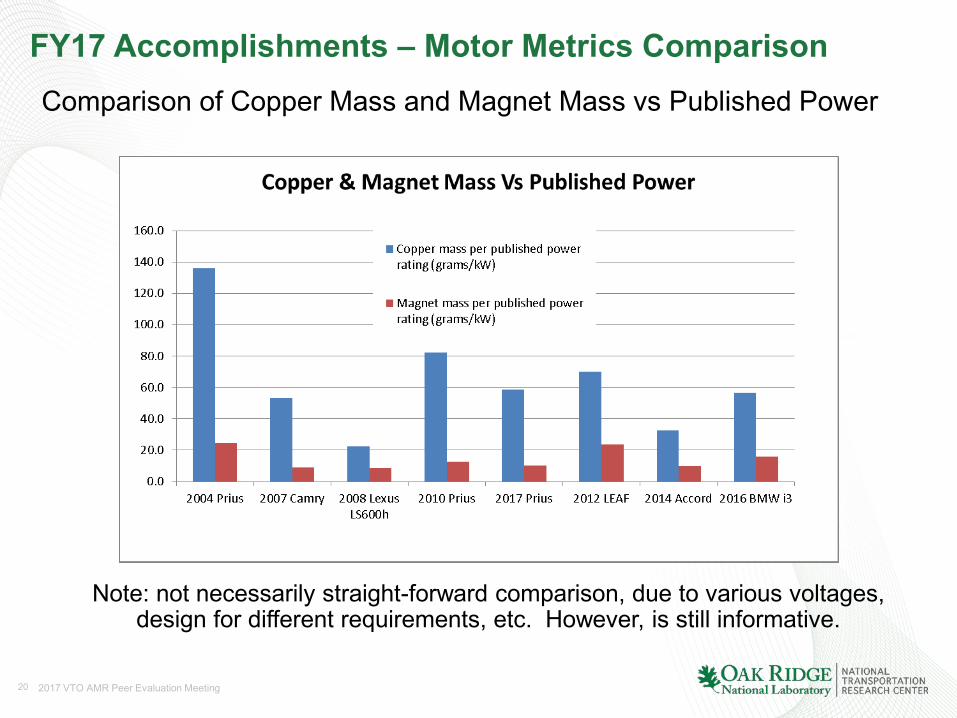
FY17 Accomplishments – Motor Metrics ComparisonComparison of Copper Mass and Magnet Mass vs Published Power
Note: not necessarily straight-forward comparison, due to various voltages, design for different requirements, etc. However, is still informative.
21 2017 VTO AMR Peer Evaluation Meeting
Responses to Previous Year Reviewers’ Comments• New start, no previous comments.
22 2017 VTO AMR Peer Evaluation Meeting
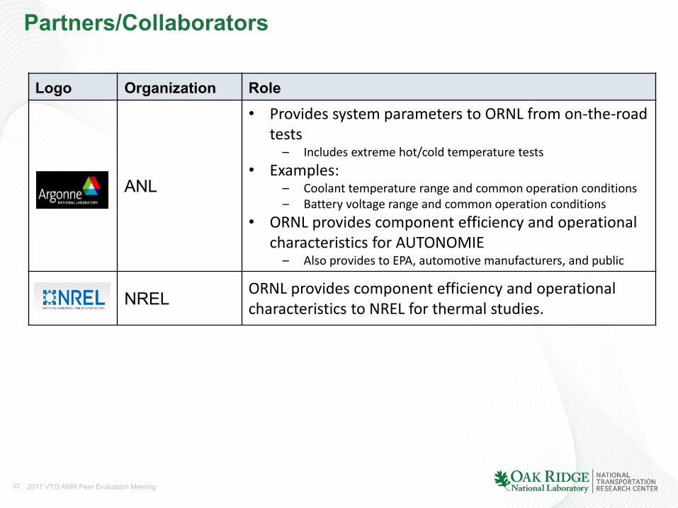
Partners/Collaborators
Logo Organization Role
ANL
• Provides system parameters to ORNL from on-the-road tests
– Includes extreme hot/cold temperature tests• Examples:
– Coolant temperature range and common operation conditions– Battery voltage range and common operation conditions
• ORNL provides component efficiency and operational characteristics for AUTONOMIE
– Also provides to EPA, automotive manufacturers, and public
NREL ORNL provides component efficiency and operational characteristics to NREL for thermal studies.
23 2017 VTO AMR Peer Evaluation Meeting
Remaining Challenges and Barriers for FY17
• Obtaining on the road EDT systems.• In your accomplishment slides, you may have shown how you’ve addressed some
of the problems with the SOA. In this slide highlight the key remaining challenges and barriers to meeting the project objectives.
• The remaining challenges and barriers should provide justification and support for the future plans in the following slide.
Any proposed future work is subject to change based on funding levels
24 2017 VTO AMR Peer Evaluation Meeting
Proposed Future Work
• Remainder of FY17– Finalize comprehensive evaluations of 2017 Prius.– Complete destructive analysis of 2017 Prius.– Complete teardown assessments of 2017 Prius.– Design interfaces for and instrument 2017 Prius for testing.
• FY18– Select commercially available EV/HEV systems relevant to DOE’s VTO mission.– Perform standard evaluations of selected system.
Any proposed future work is subject to change based on funding levels
25 2017 VTO AMR Peer Evaluation Meeting
Summary
• Relevance: The core function of this project is to confirm power electronics and electric motor technology status and identify barriers and gaps to prioritize/identify R&D opportunities.
• Approach: The approach is to select leading EV/HEV technologies, disassemble them for design/packaging assessments, and test them over entire operation region.
• Collaborations: Interactions are ongoing with other national laboratories, industry, and other government agencies.
• Technical Accomplishments: Tested and reported on more than eight EV/HEV systems including recent efforts on the 2016 BMW i3 and 2017 Prius inverter and motor.
• Future work: Complete Accord HEV dynamometer testing and continue evaluating 2017 Prius.
Any proposed future work is subject to change based on funding levels