Electrical - New & Used Bus Dealer | Coach, Shuttle & School … · 2006-11-30 · Figure...
113
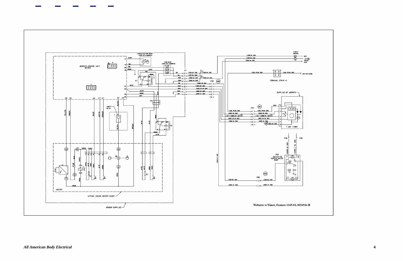
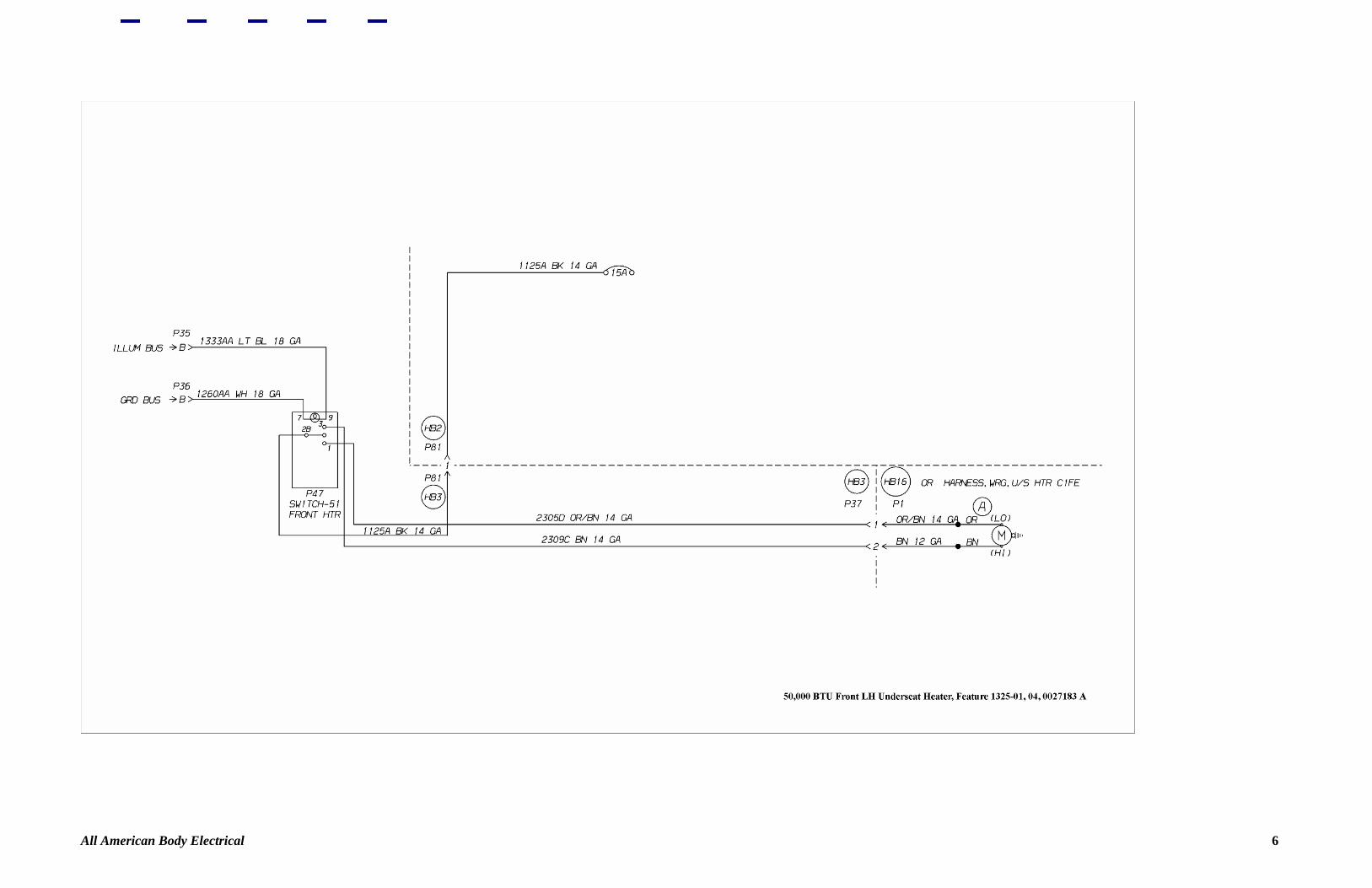
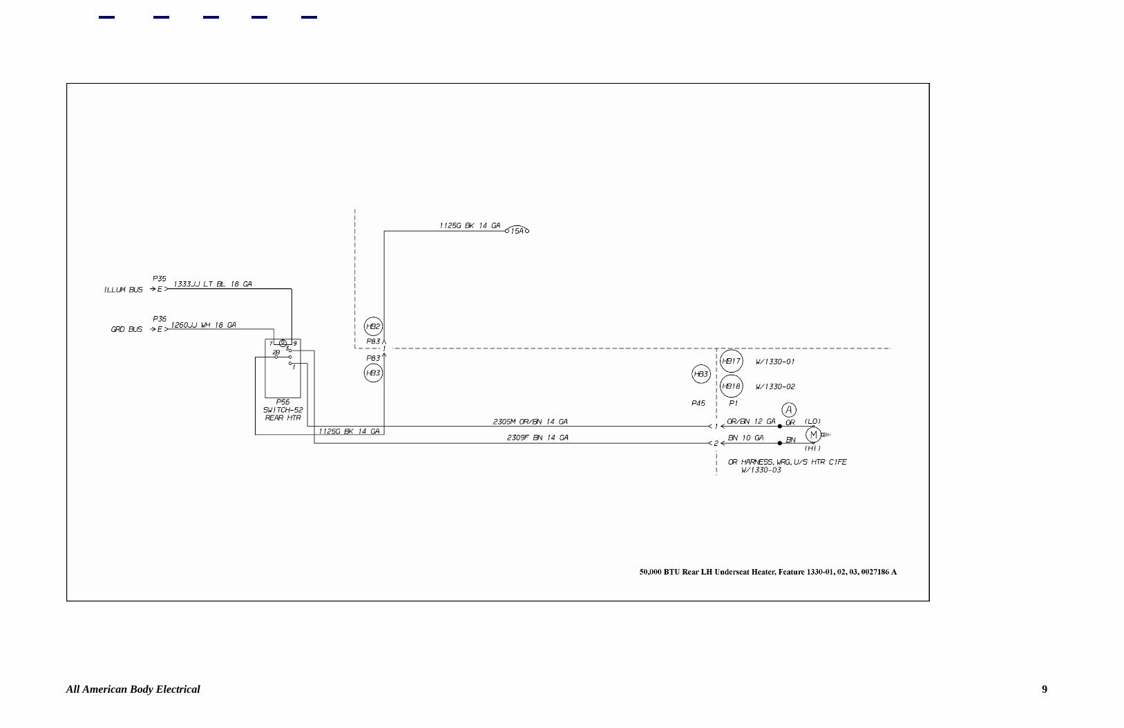
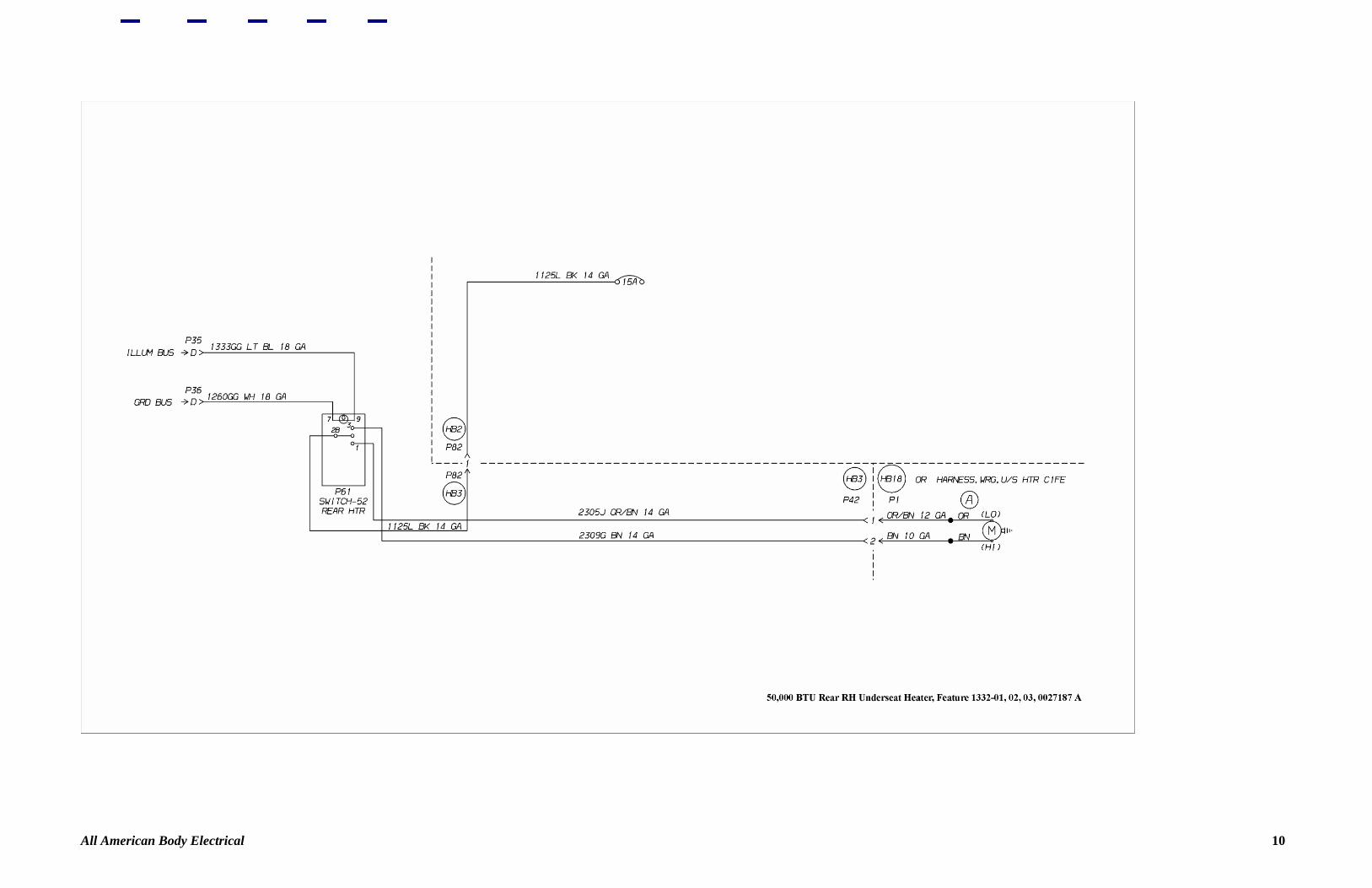
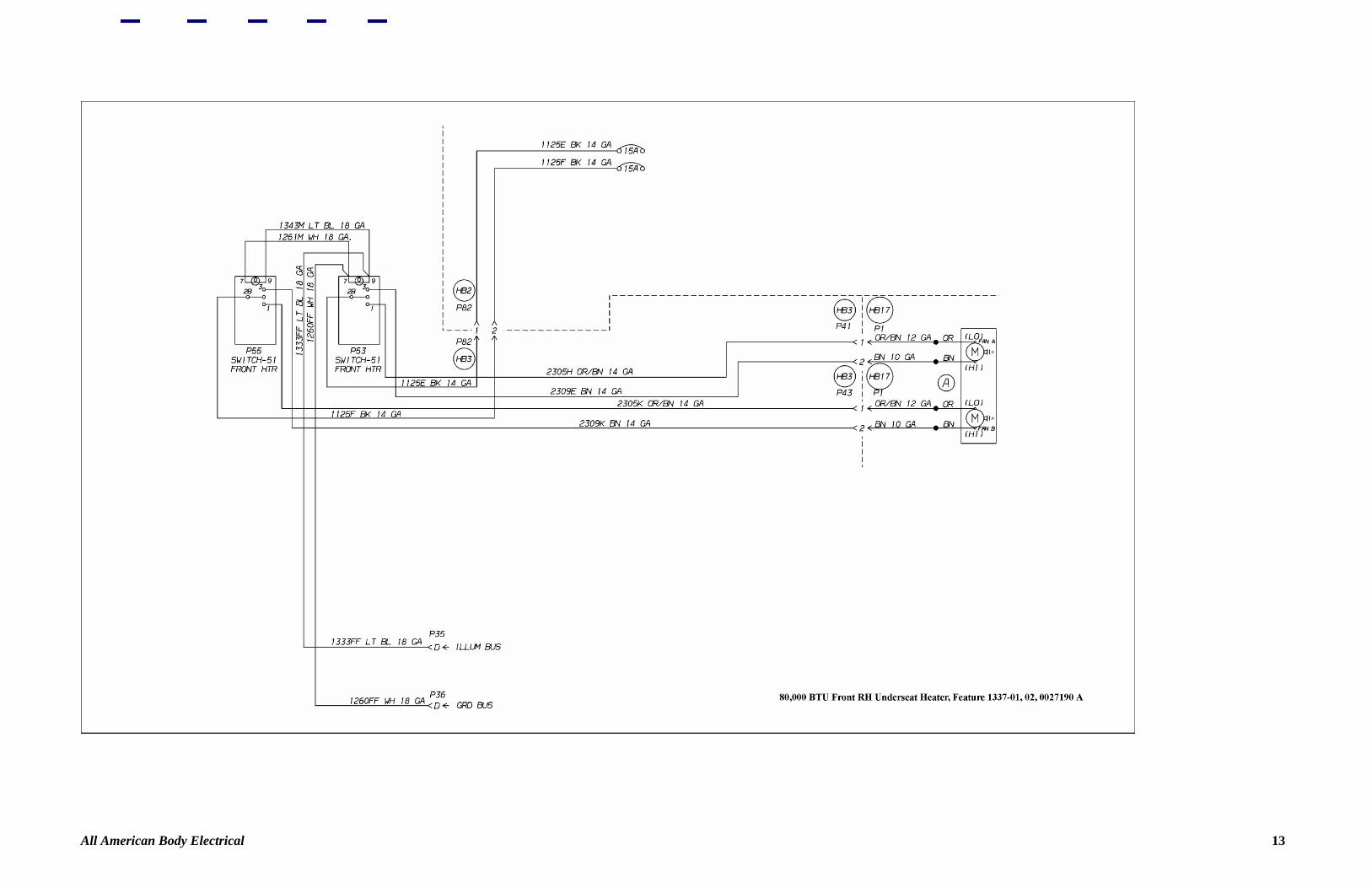
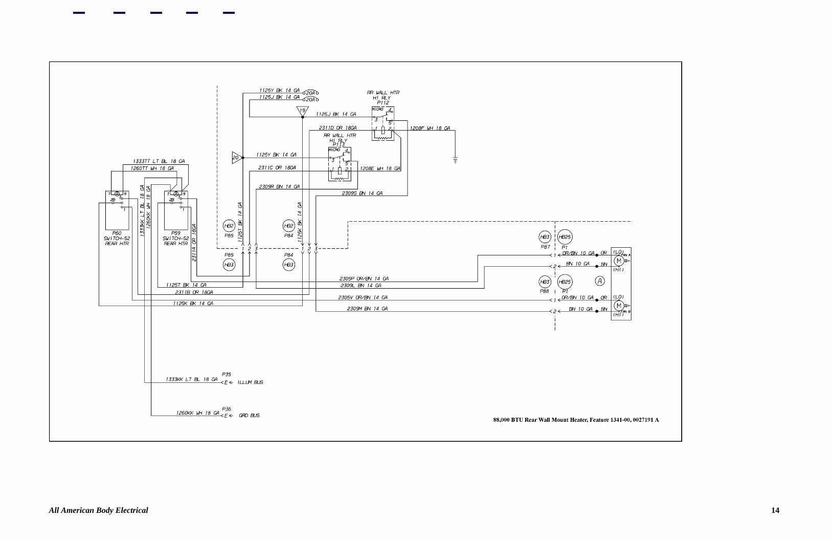
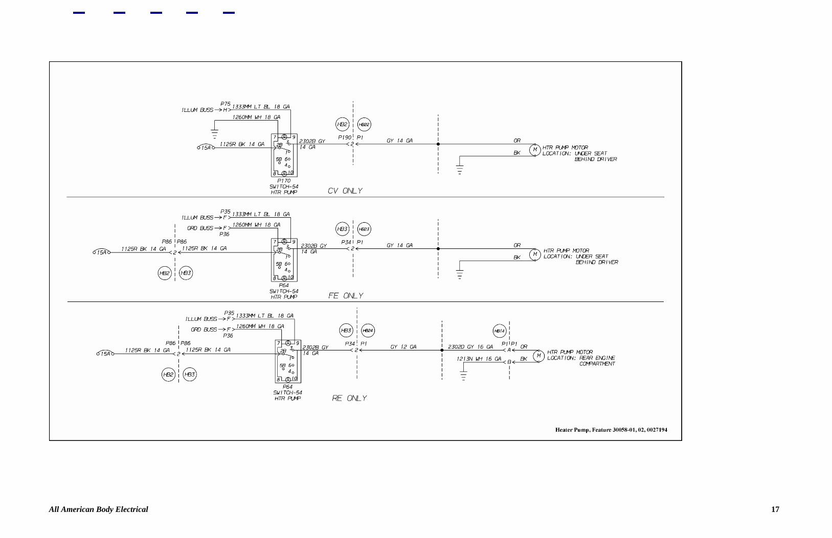
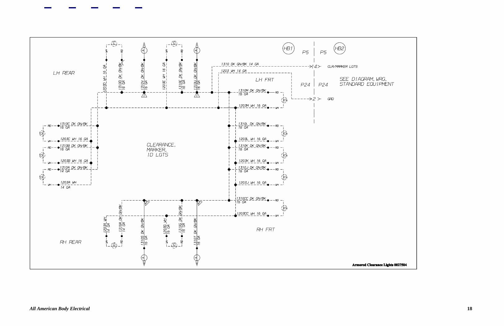
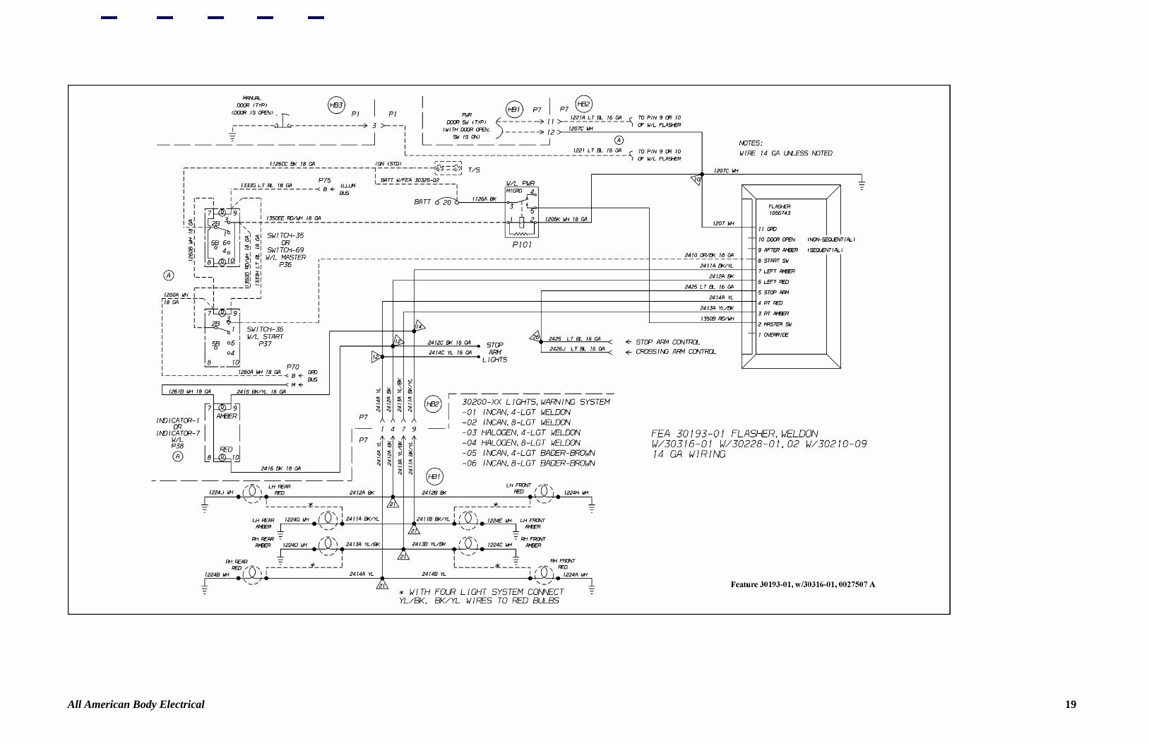
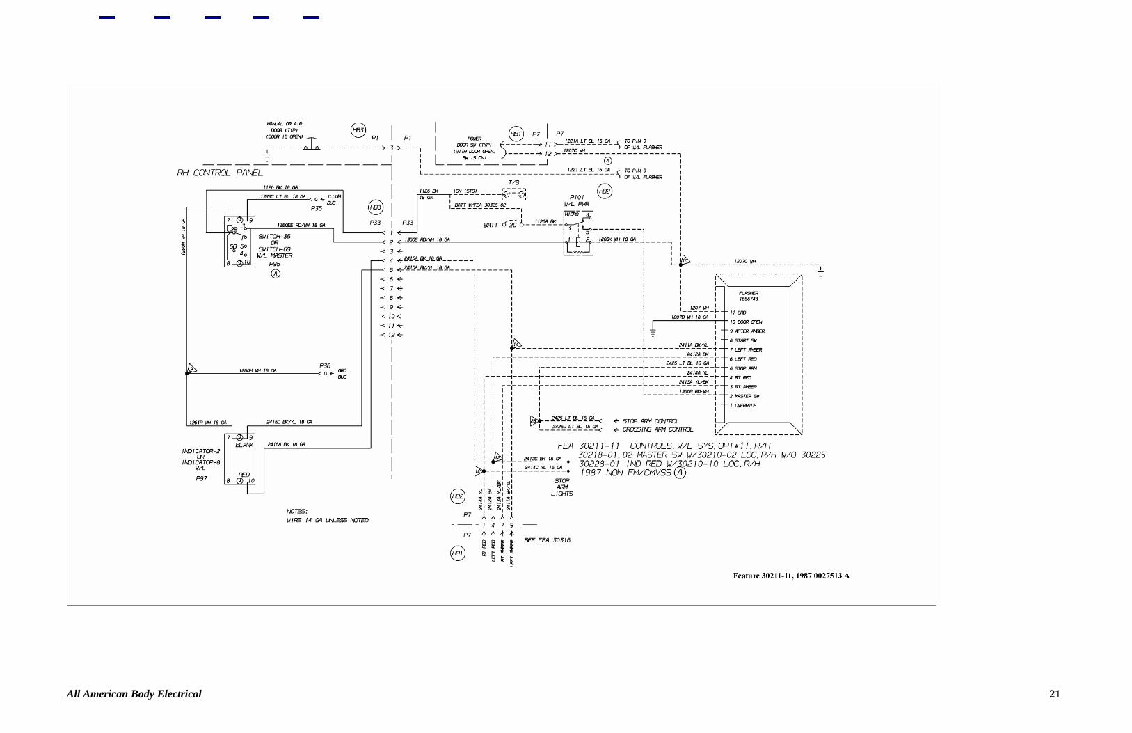
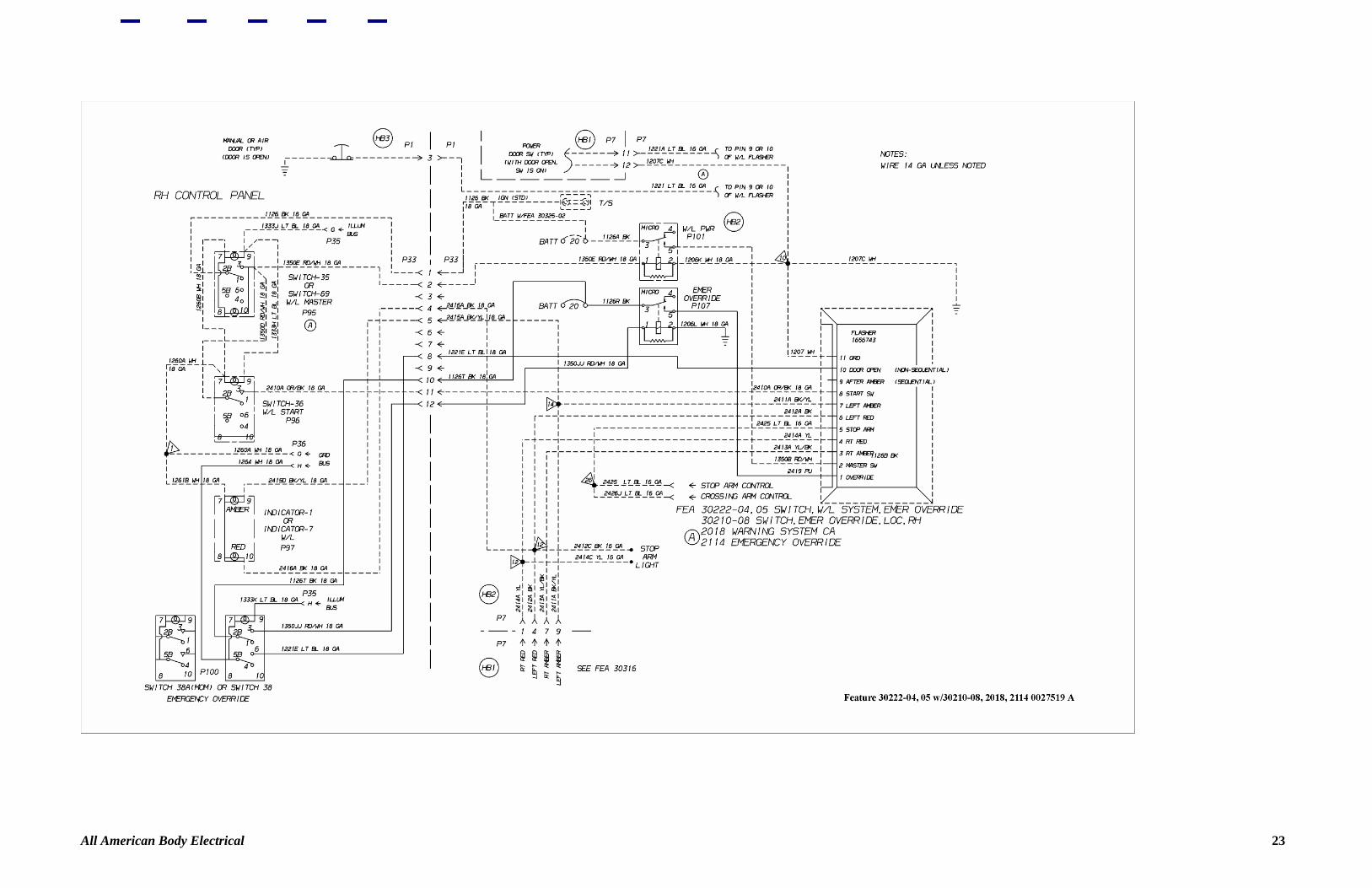
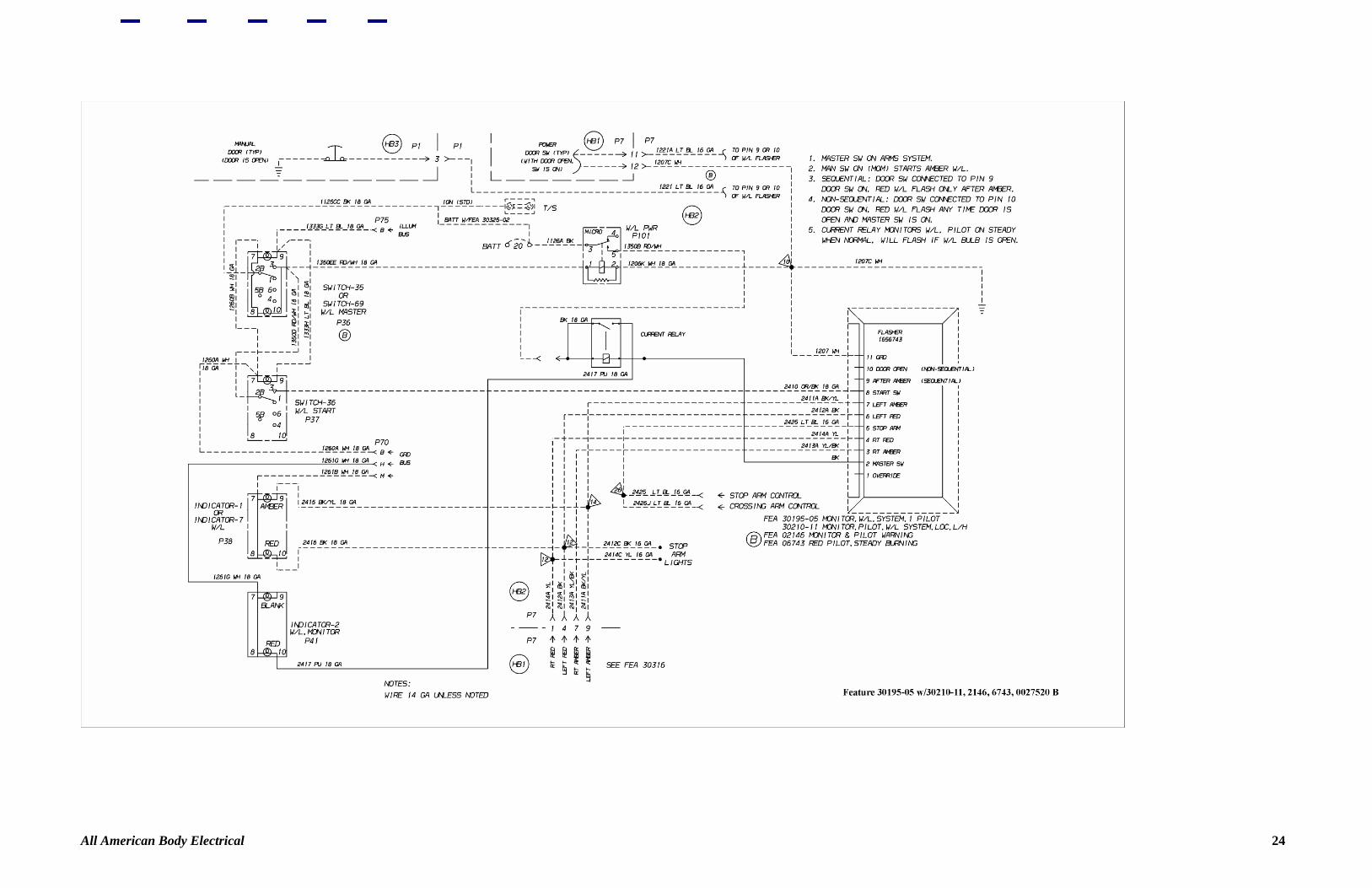
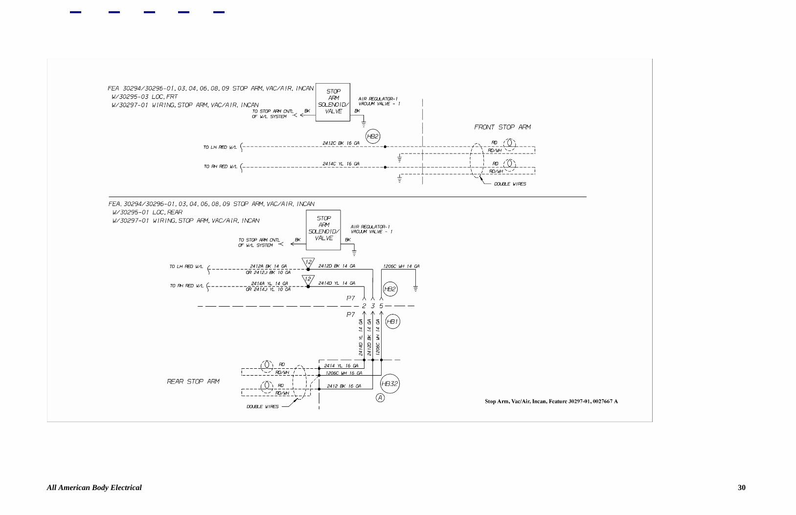
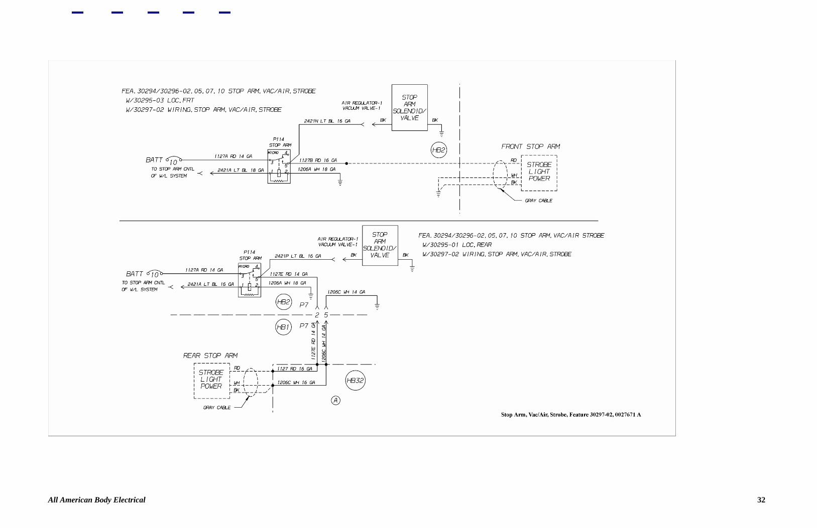
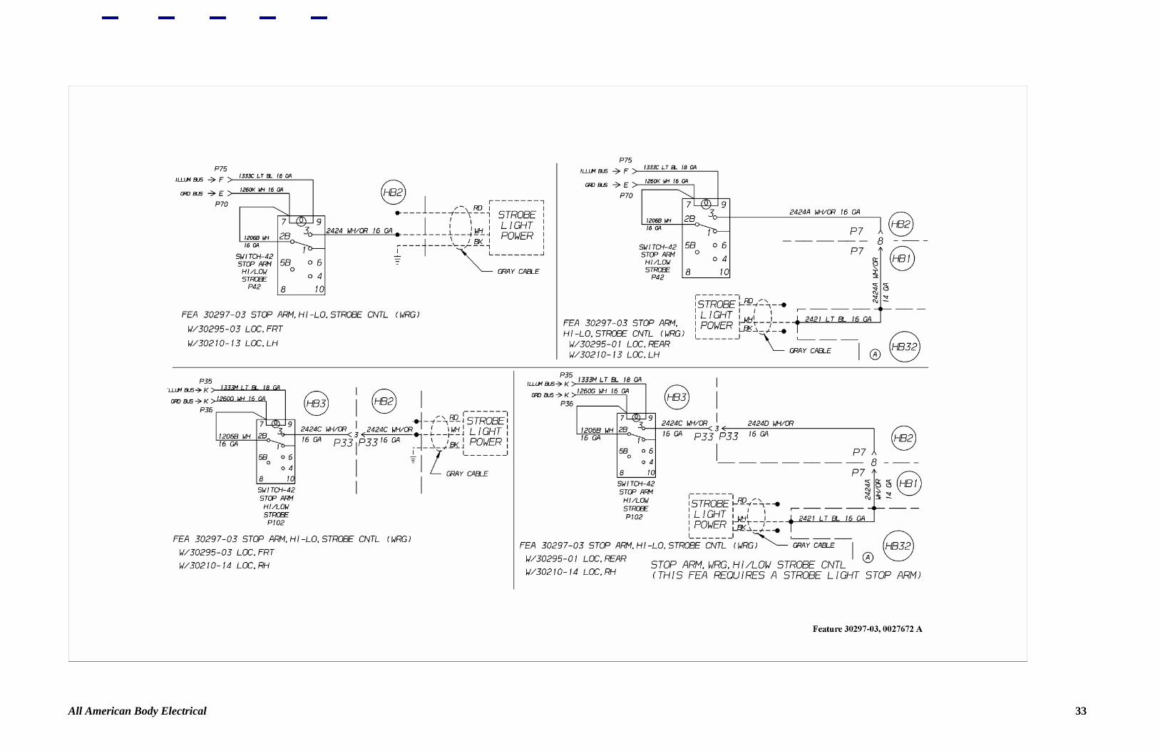
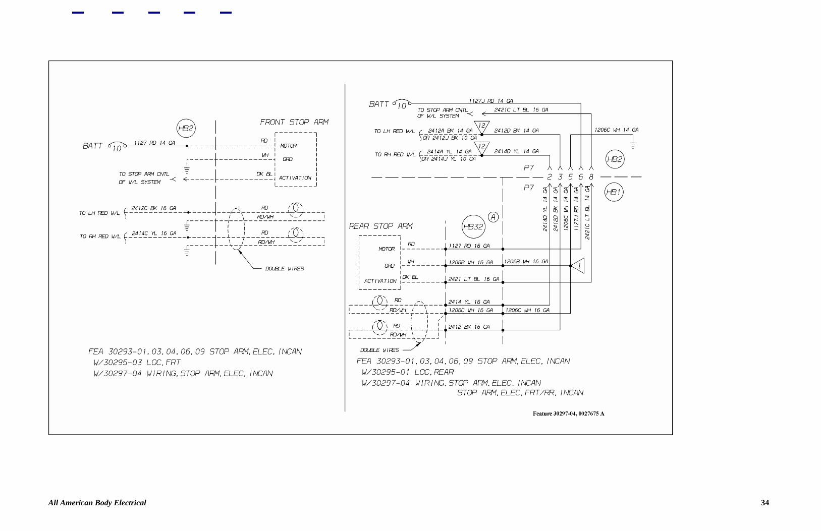
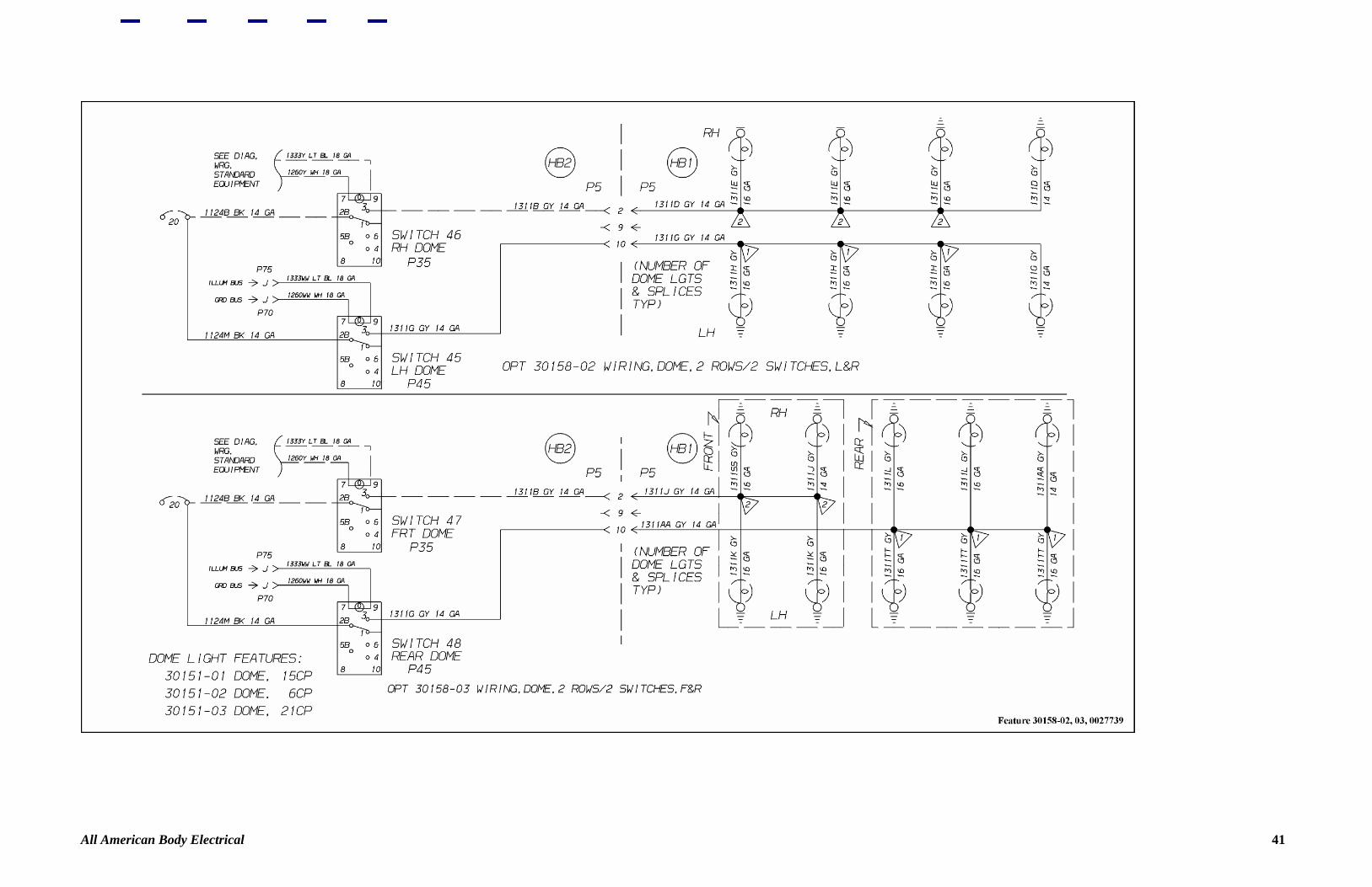
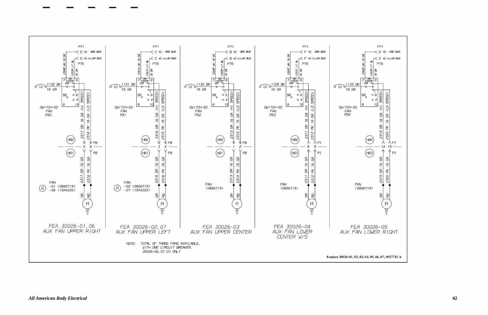
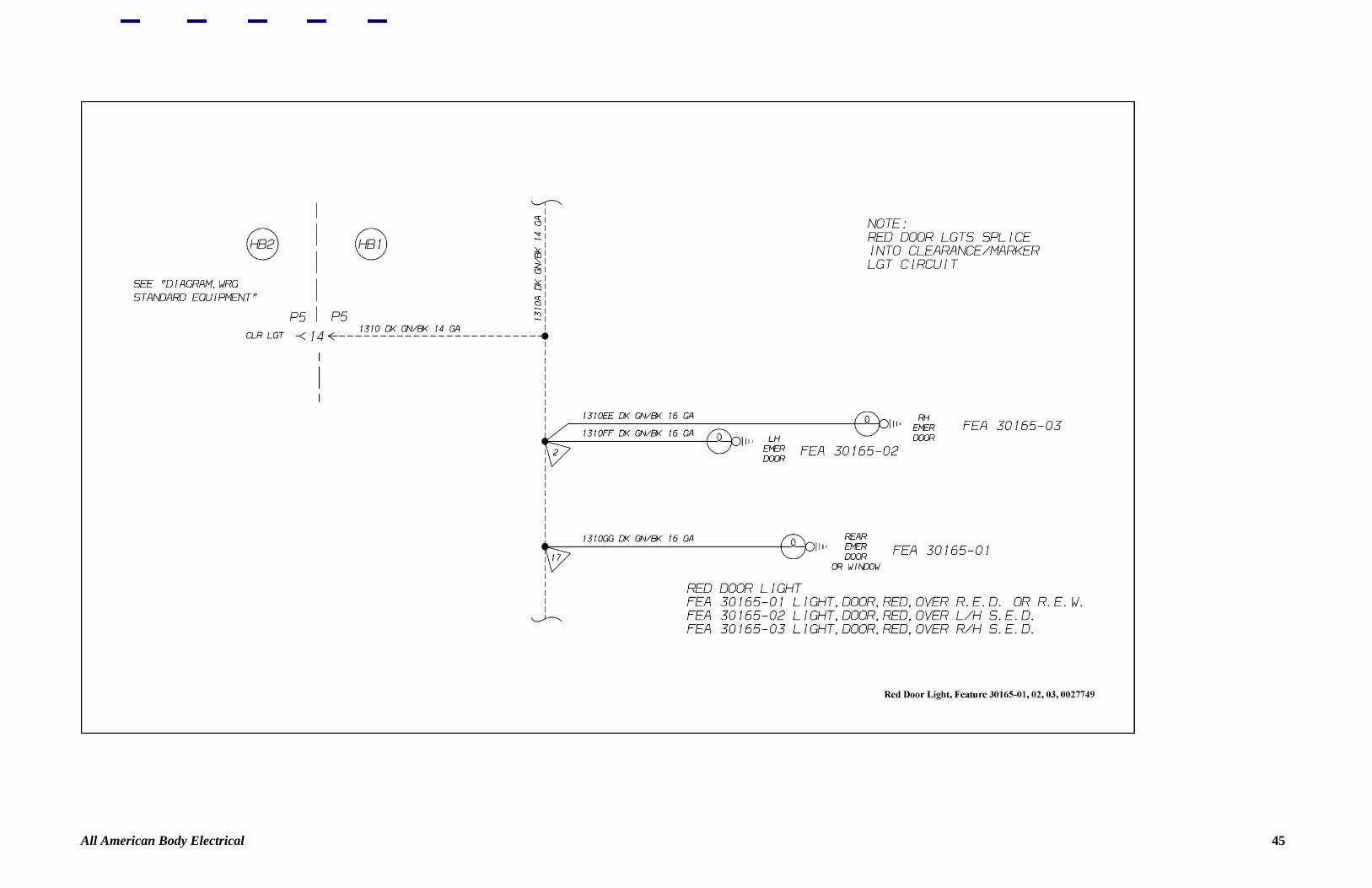
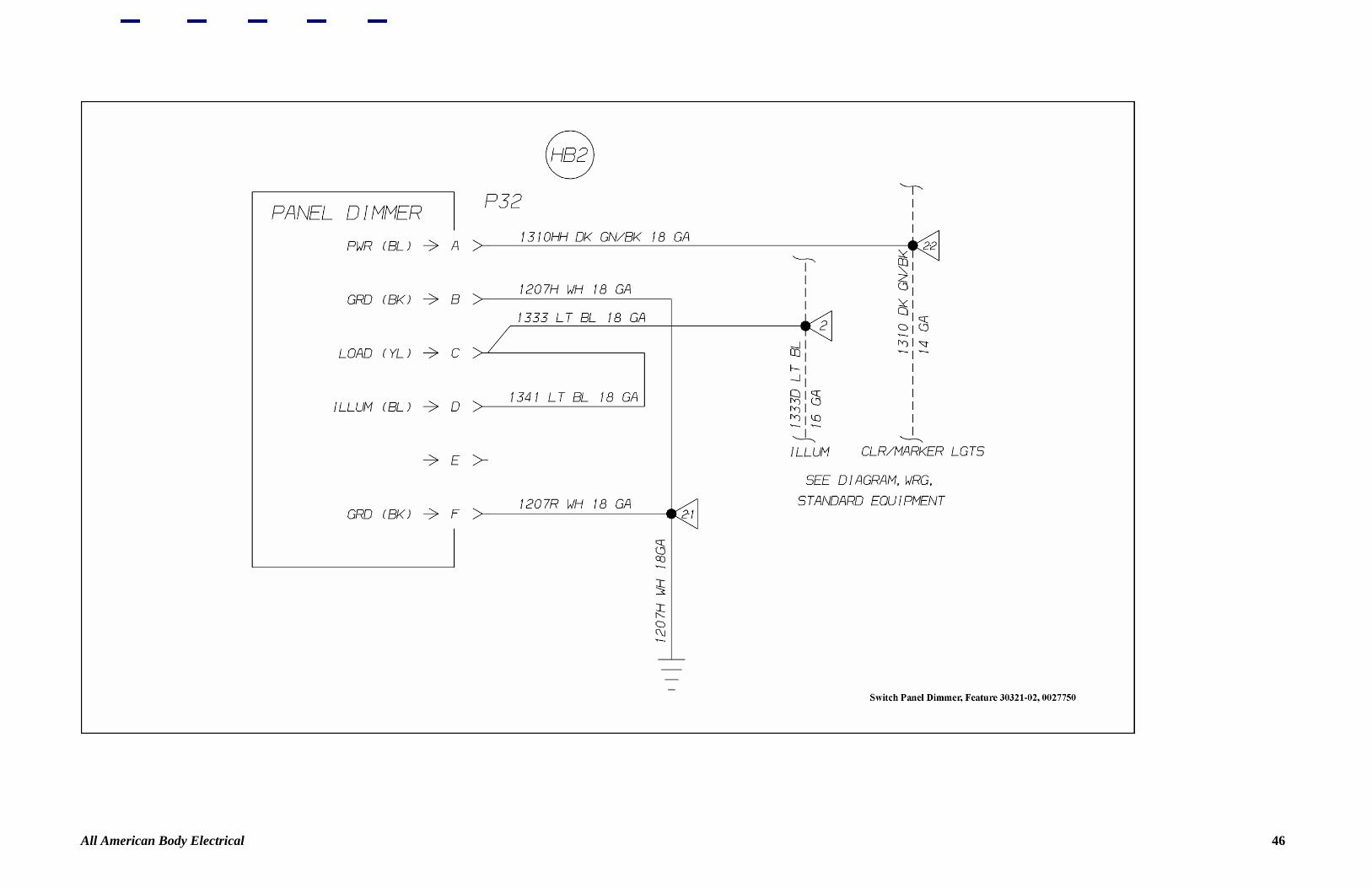
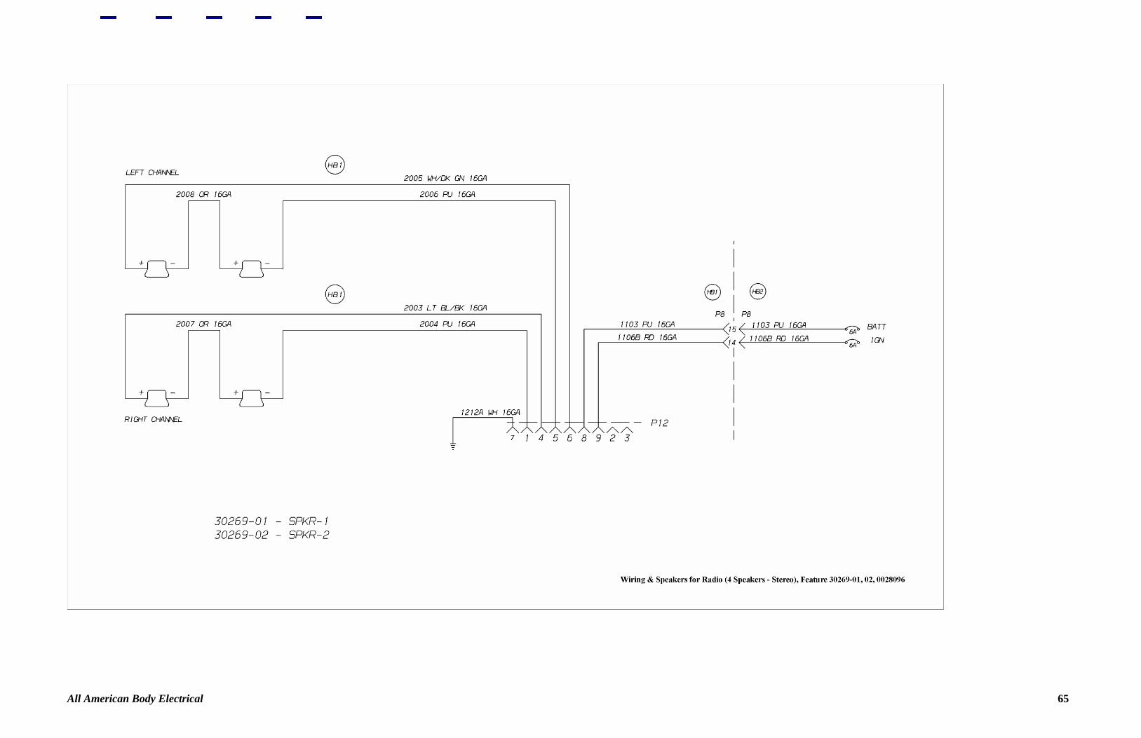
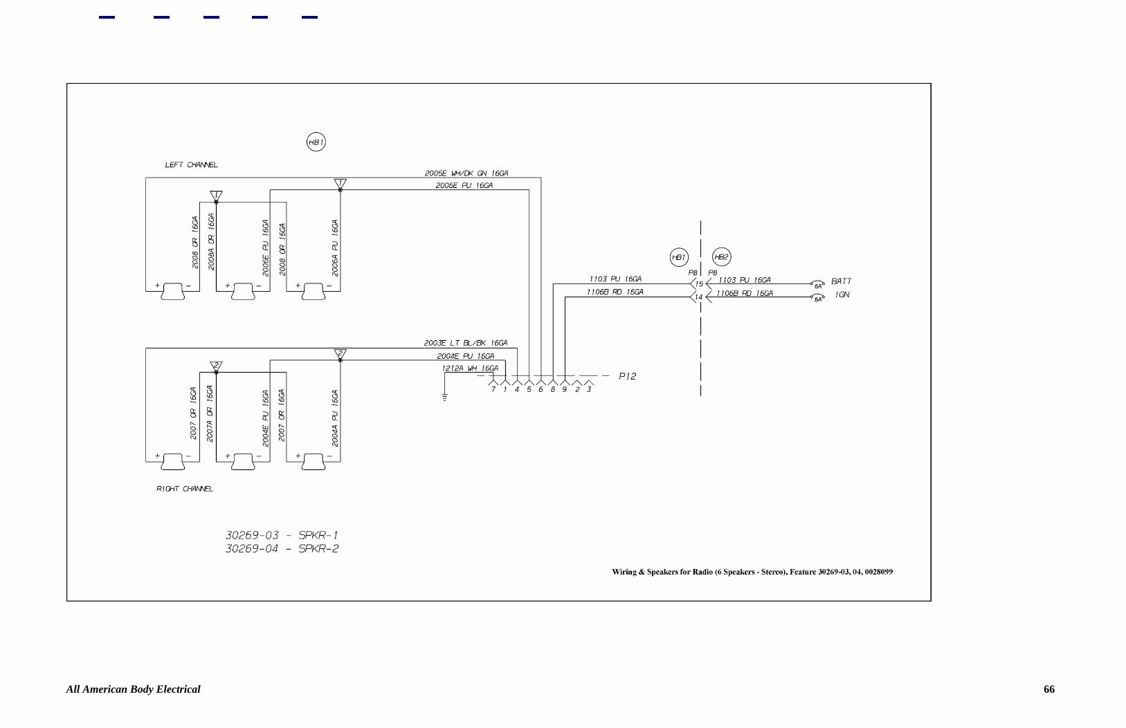
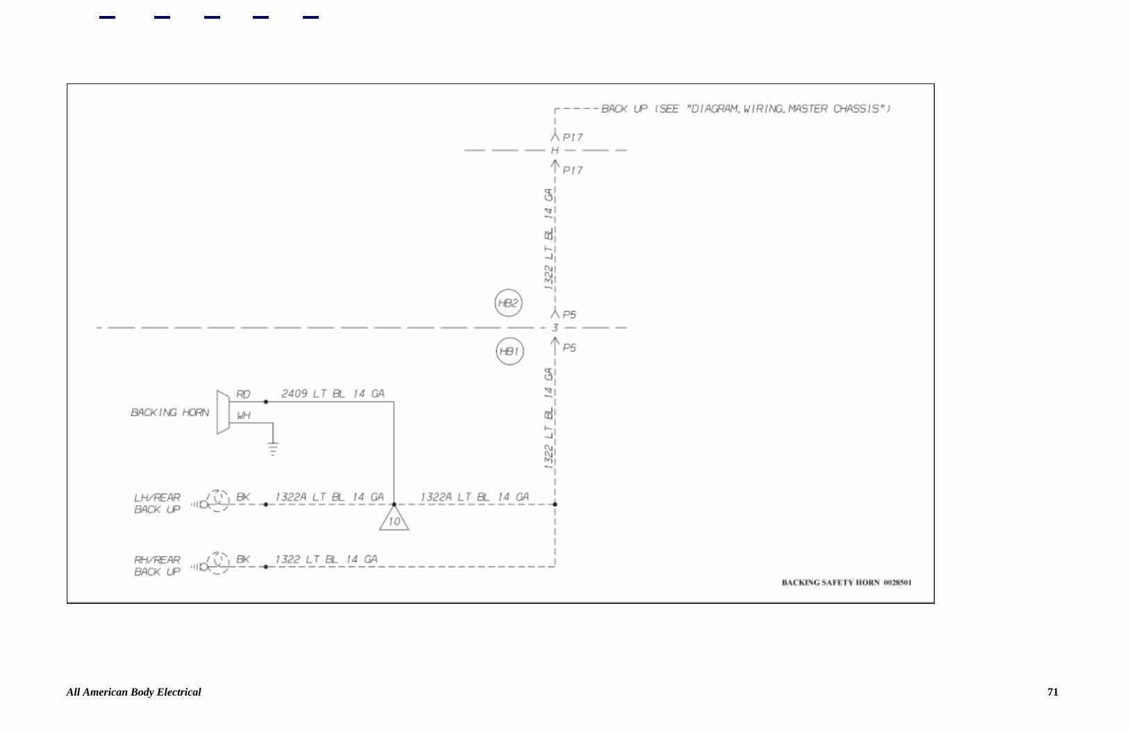
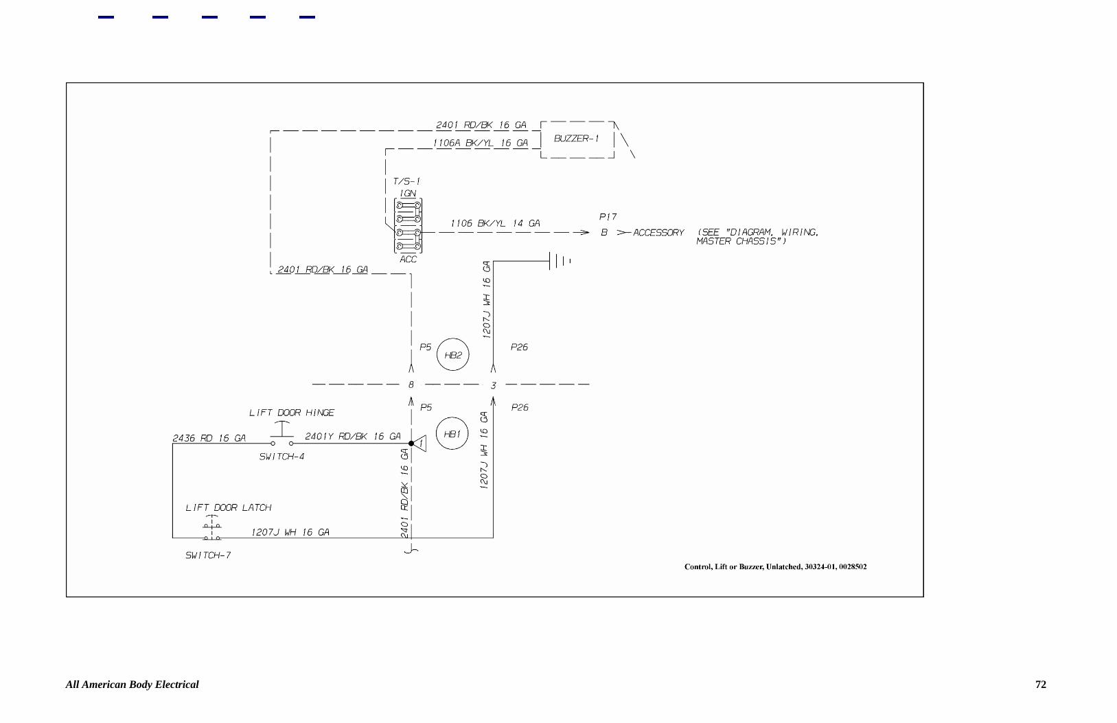
Body Electrical Note The Electrical portion of the Blue Bird All American Service Manual is divided into two sections. One section is for the chassis electrical and the other section is for the body electrical. List of Figures Figure 1—Instructions, Symbols, Wiring, Body 3 Figure 2—Webasto with Timer 4 Figure 3—Heater and Defroster, Kysor 5 Figure 4—50K BTU Front LH Underseat Heater 6 Figure 5—50K BTU Front LH Underseat Heater 7 Figure 6—50K BTU Front RH Underseat Heater 8 Figure 7—50K BTU Underseat Heater 9 Figure 8—50K BTU Rear RH Underseat Heater 10 Figure 9—80K BTU Front LH Underseat Heater 11 Figure 10—80K BTU Front LH Underseat Heaters 12 Figure 11—80K BTU Front RH Underseat Heater 13 Figure 12—80K BTU Rear Wall Mount Heater 14 Figure 13—80K BTU LH Rear Underseat Heater 15 Figure 14—80K BTU RH Underseat Heater 16 Figure 15—Heater Pump 17 Figure 16—Armored Clearance Light 18 Figure 17—Feature 30193-01 19 Figure 18—Feature 30193-01 20 Figure 19—Feature 30211-11 21 Figure 20—Feature 30211-09 22 Figure 21—Feature 30222-04, 05 23 Figure 22—Feature 30195-05 24 Figure 23—Feature 30211-05 25 Figure 24—Driver's Underseat 26 Figure 25—Feature 30227-01 27 Figure 26—Vandal Lock Left Side 28 Figure 27—Vandal Lock Right Side 29 Figure 28—Stop Arm, Vac Air 30 Figure 29—Power, Body Controls 31 Figure 30—Stop Arm, Vac Air 02 32 Figure 31—Feature 30297-03 33 Figure 32—Feature 30297-04 34 Figure 33—Stop Arm, Electric 35 Figure 34—Feature 30211-14 36 Figure 35—Right Hand Drive 37 Figure 36—School Bus Signs 38 Figure 37—Lights, Dome, Driver 39 Figure 38—Feature 30158-01 40 Figure 39—Feature 30158-02 41 Figure 40—Feature 30026-01-07 42 Figure 41—Feature 30157-01-05 43 Figure 42—Dome Lights Activated By Emergency Exits 44 Figure 43—Red Door Light 45 Figure 44—Switch Panel Dimmer 46 Figure 45—Daytime Running Lights Low Intensity 47 Figure 46—Daytime Running Lights 48 Figure 47—Dual Windshield Wiper Switches 49 Figure 48—Single Intermittent Windshield Wiper Switches 50 Figure 49—Dual Intermittent Windshield Wiper Switches 51 Figure 50—Passenger Signal Chime 52 Figure 51—Dome Lights Activated By Emergency Exits 53 Figure 52—Dome Lights Activated By Emergency Exits 54 Figure 53—Exhaust Fan 55 Figure 54—Feature 30029-01-03 56 Figure 55—Rear Center Luggage Compartment Wiring 57 Figure 56—Feature 6164, 6165, 6184 58 Figure 57—Feature 30173, 30174 59 Figure 58—Brake Interlock 60 Figure 59—Feature 30148 61 Figure 60—Interlock, Lift 62 Figure 61—Locking Emergency Equipment 63 Figure 62—Radio, Feature 30260 64 Figure 63—Wiring/Speakers, Radio 65 Figure 64—Wiring/Speakers, Radio 66 Figure 65—Speakers for Radio 67 Figure 66—Feature 30269 68 Figure 67—Door Switch, Ground to Warning Systems 69 Figure 68—Backing Safety Horn 70 Figure 69—Backing Safety Horn 71 Figure 70—Control, Lift or Buzzer 73 Figure 71—Lift Door Buzzer Control 73 Figure 72—Switch, Lift Door, Lights 74 Figure 73—Lift Pendant Control 75 Figure 74—P/O Window 76 Figure 75—Emergency Exit Pilot Light 77 All American Body Electrical 1
-
Upload
truongthuan -
Category
Documents
-
view
213 -
download
0
Transcript of Electrical - New & Used Bus Dealer | Coach, Shuttle & School … · 2006-11-30 · Figure...
Body Electrical
Note The Electrical portion of the Blue Bird All American Service Manual is divided into two sections. One section is for the chassis electrical and the other section is for the body electrical. List of Figures Figure 1—Instructions, Symbols, Wiring, Body 3 Figure 2—Webasto with Timer 4 Figure 3—Heater and Defroster, Kysor 5 Figure 4—50K BTU Front LH Underseat Heater 6 Figure 5—50K BTU Front LH Underseat Heater 7 Figure 6—50K BTU Front RH Underseat Heater 8 Figure 7—50K BTU Underseat Heater 9 Figure 8—50K BTU Rear RH Underseat Heater 10 Figure 9—80K BTU Front LH Underseat Heater 11 Figure 10—80K BTU Front LH Underseat Heaters 12 Figure 11—80K BTU Front RH Underseat Heater 13 Figure 12—80K BTU Rear Wall Mount Heater 14 Figure 13—80K BTU LH Rear Underseat Heater 15 Figure 14—80K BTU RH Underseat Heater 16
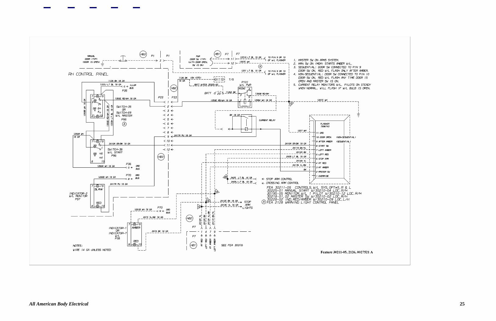
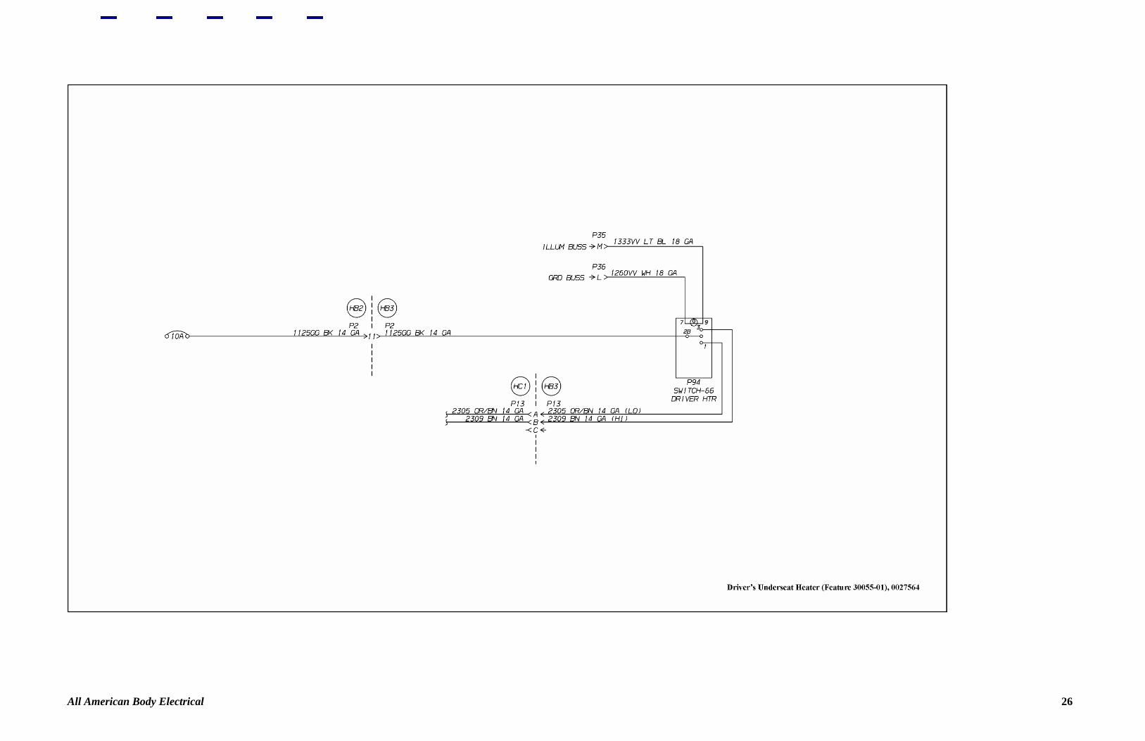
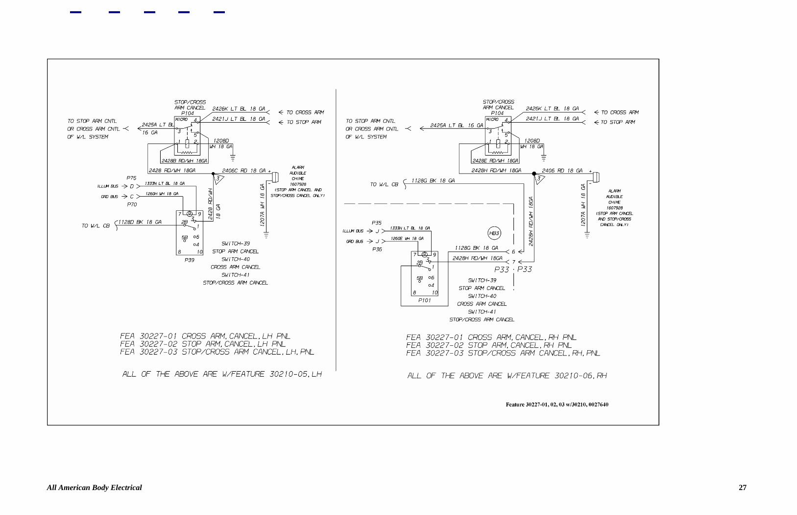
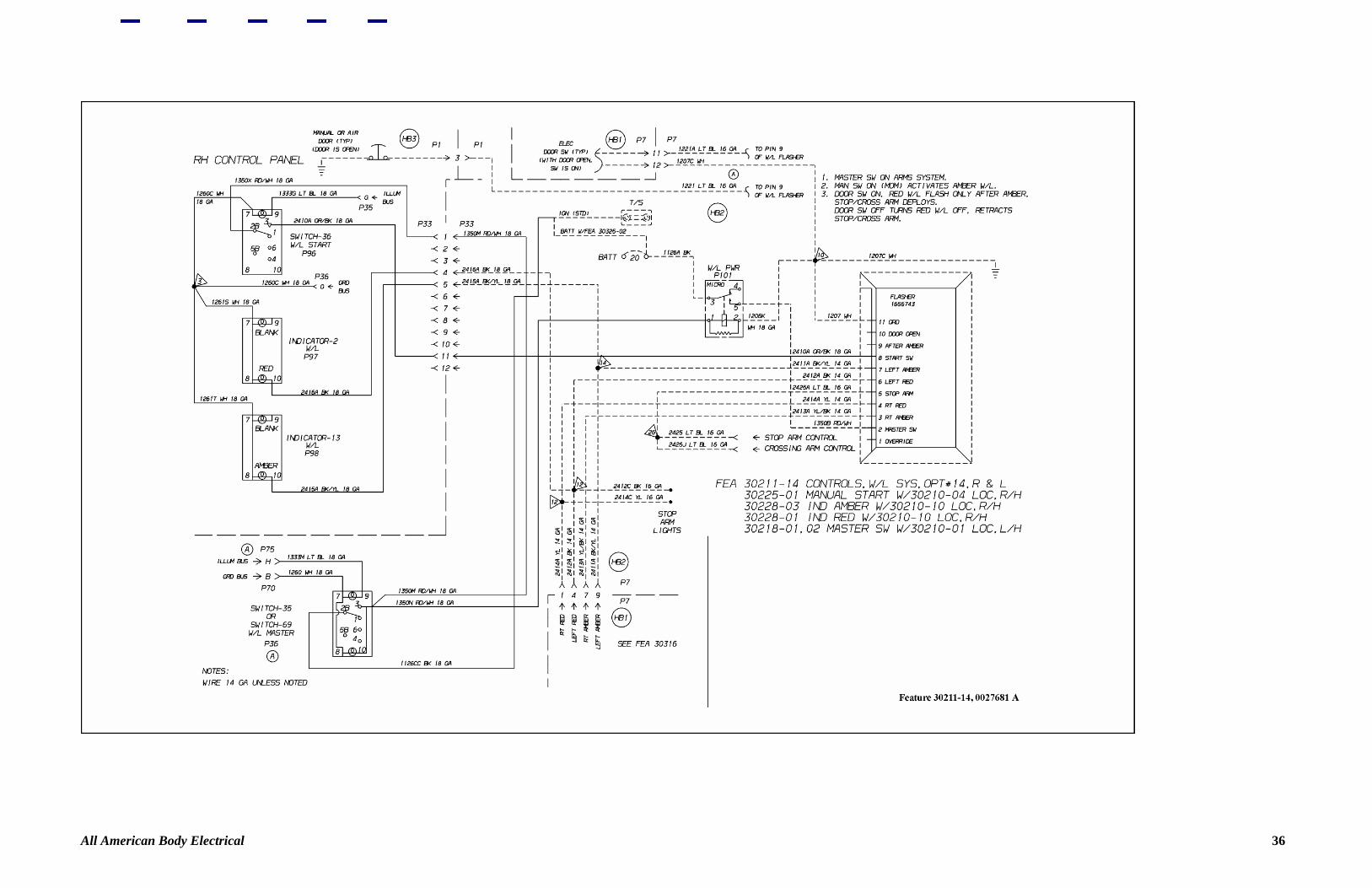
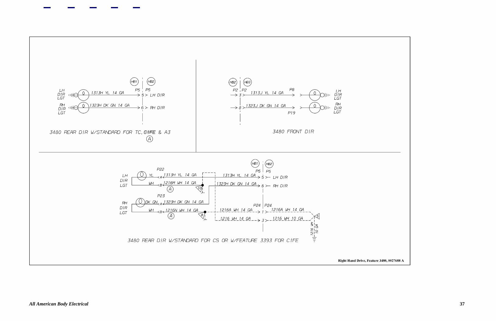
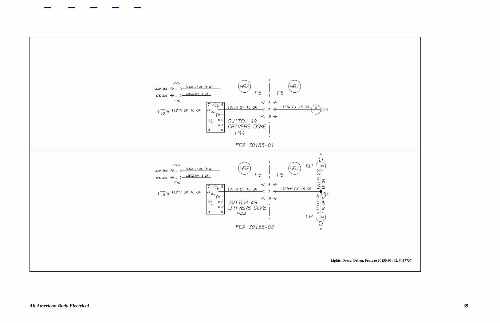
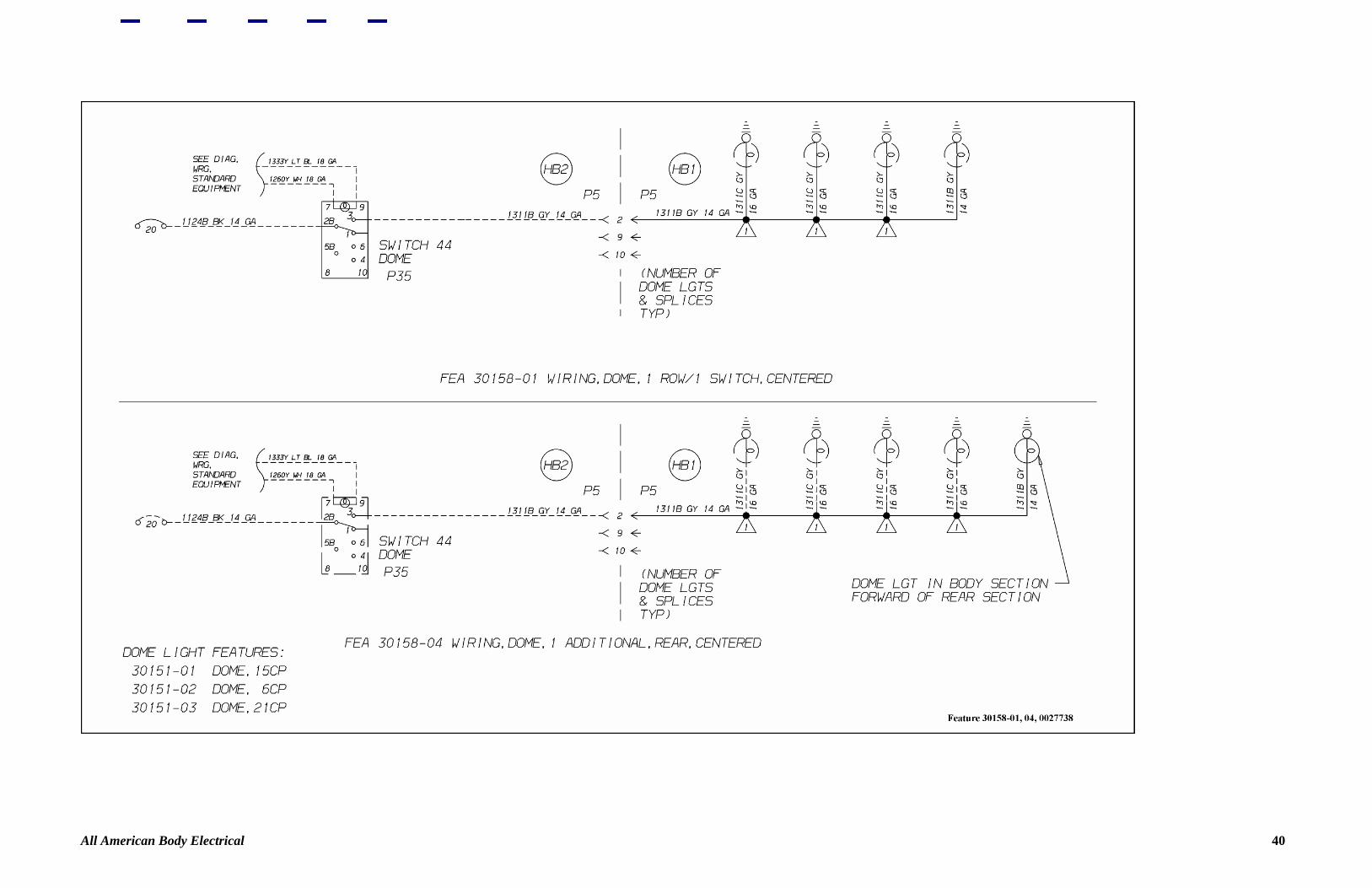
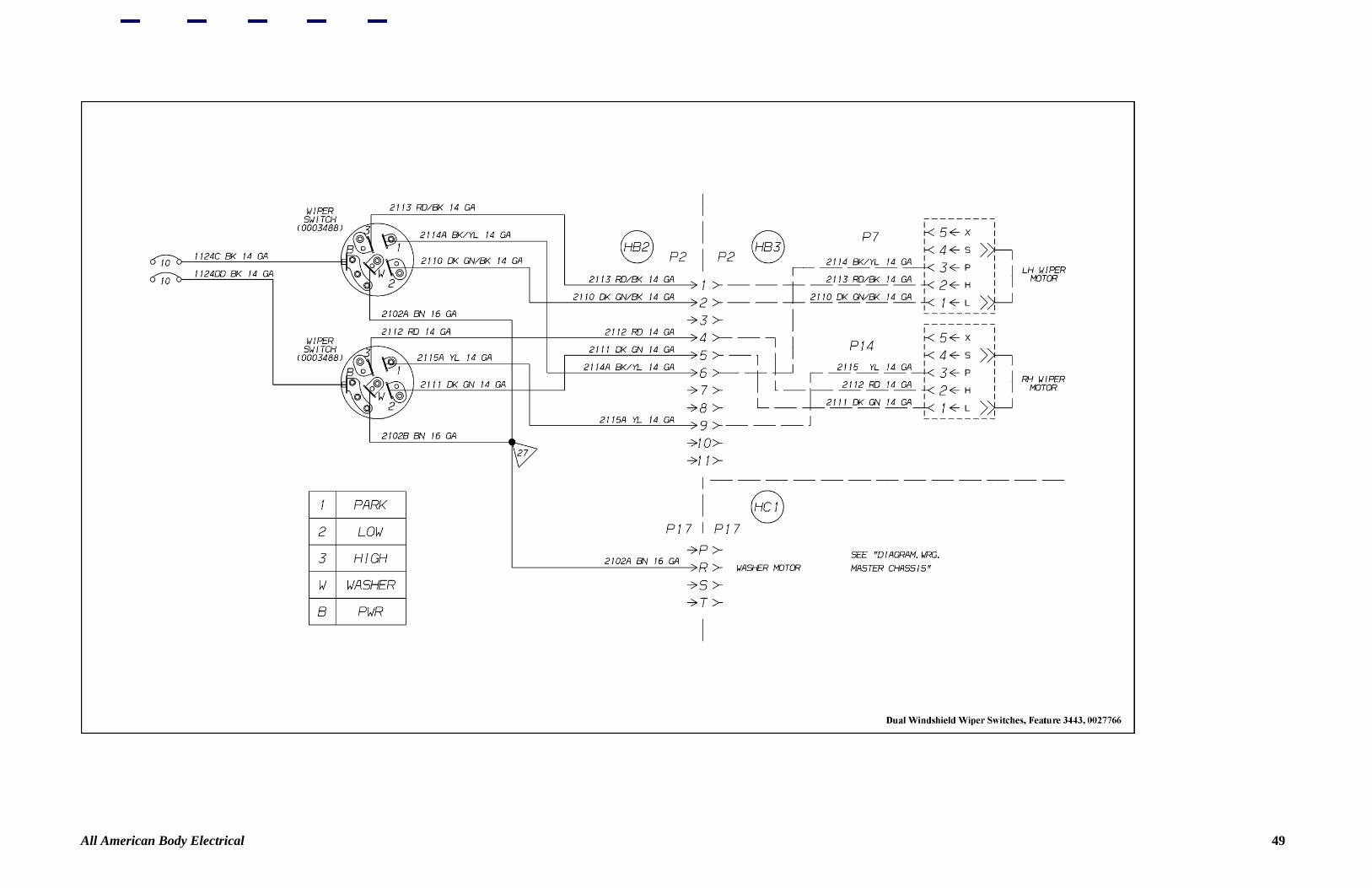
Figure 15—Heater Pump 17 Figure 16—Armored Clearance Light 18 Figure 17—Feature 30193-01 19 Figure 18—Feature 30193-01 20 Figure 19—Feature 30211-11 21 Figure 20—Feature 30211-09 22 Figure 21—Feature 30222-04, 05 23 Figure 22—Feature 30195-05 24 Figure 23—Feature 30211-05 25 Figure 24—Driver's Underseat 26 Figure 25—Feature 30227-01 27 Figure 26—Vandal Lock Left Side 28 Figure 27—Vandal Lock Right Side 29 Figure 28—Stop Arm, Vac Air 30 Figure 29—Power, Body Controls 31 Figure 30—Stop Arm, Vac Air 02 32 Figure 31—Feature 30297-03 33 Figure 32—Feature 30297-04 34 Figure 33—Stop Arm, Electric 35 Figure 34—Feature 30211-14 36 Figure 35—Right Hand Drive 37 Figure 36—School Bus Signs 38 Figure 37—Lights, Dome, Driver 39 Figure 38—Feature 30158-01 40 Figure 39—Feature 30158-02 41 Figure 40—Feature 30026-01-07 42 Figure 41—Feature 30157-01-05 43 Figure 42—Dome Lights Activated By Emergency Exits 44 Figure 43—Red Door Light 45 Figure 44—Switch Panel Dimmer 46 Figure 45—Daytime Running Lights Low Intensity 47 Figure 46—Daytime Running Lights 48 Figure 47—Dual Windshield Wiper Switches 49
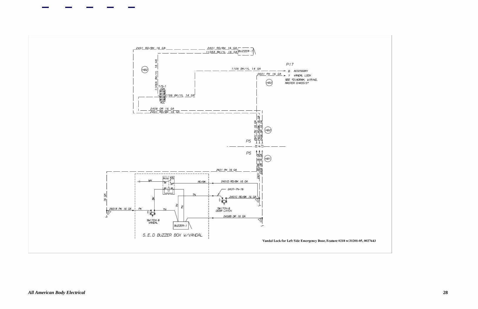
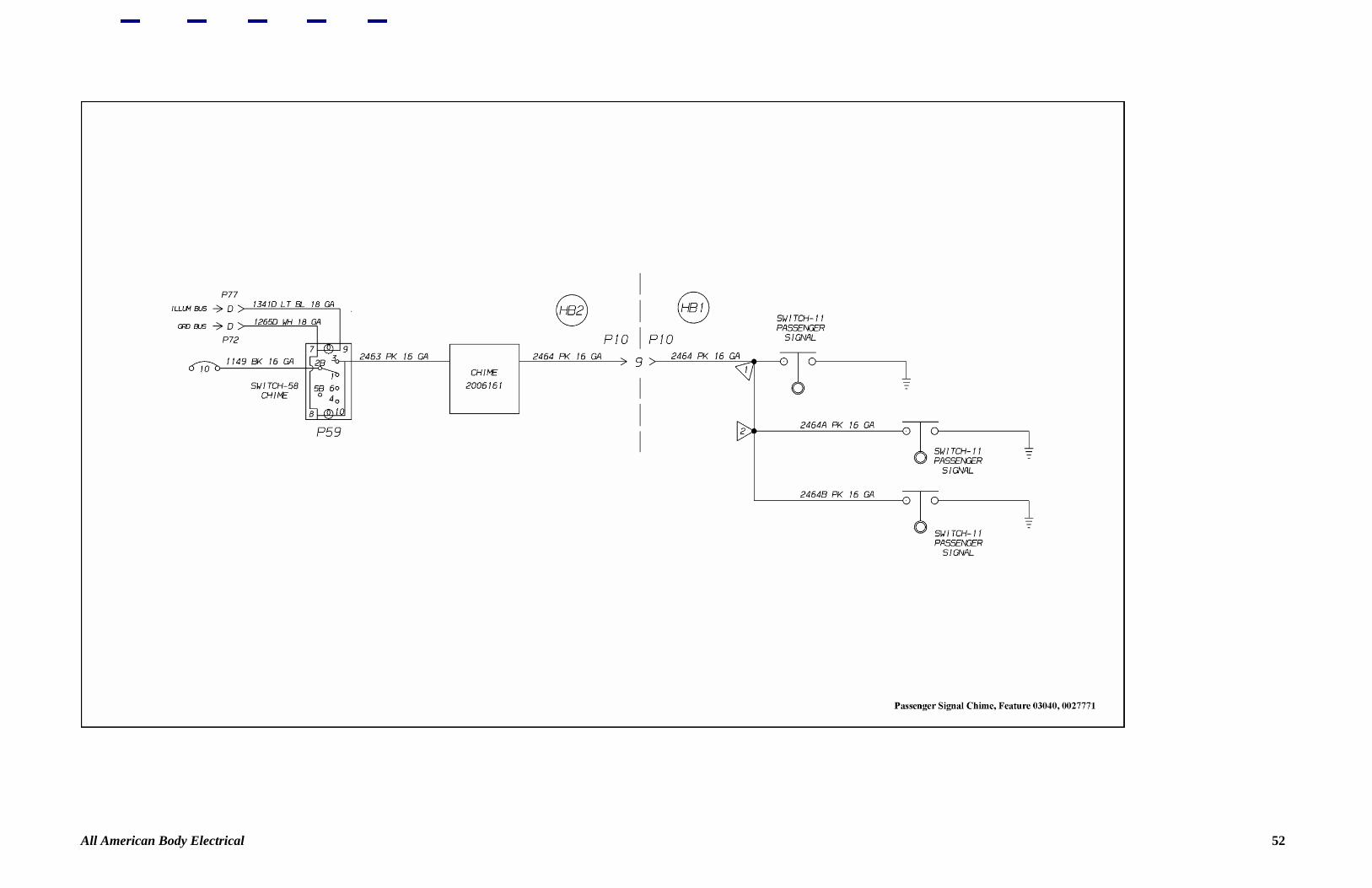
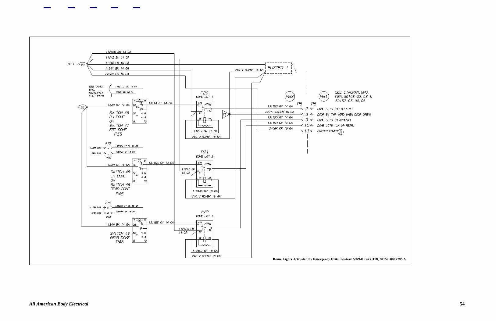
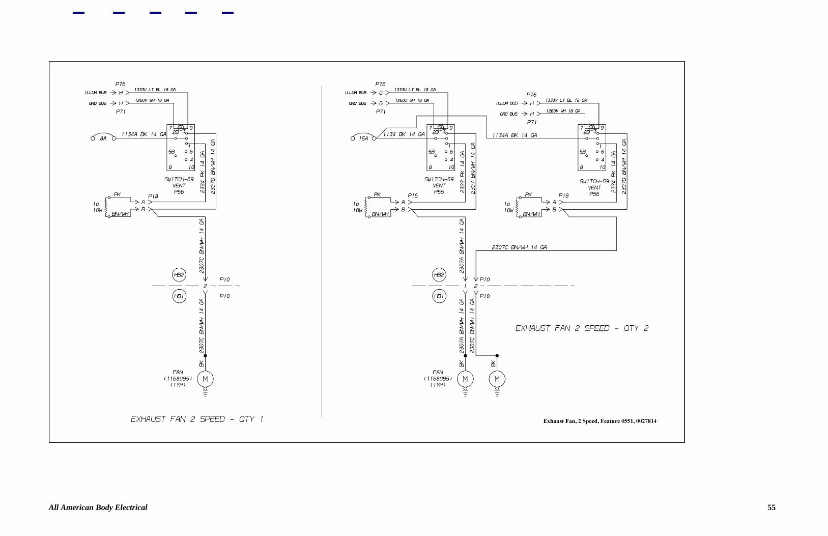
Figure 48—Single Intermittent Windshield Wiper Switches 50 Figure 49—Dual Intermittent Windshield Wiper Switches 51 Figure 50—Passenger Signal Chime 52 Figure 51—Dome Lights Activated By Emergency Exits 53 Figure 52—Dome Lights Activated By Emergency Exits 54 Figure 53—Exhaust Fan 55 Figure 54—Feature 30029-01-03 56 Figure 55—Rear Center Luggage Compartment Wiring 57 Figure 56—Feature 6164, 6165, 6184 58 Figure 57—Feature 30173, 30174 59 Figure 58—Brake Interlock 60 Figure 59—Feature 30148 61 Figure 60—Interlock, Lift 62 Figure 61—Locking Emergency Equipment 63 Figure 62—Radio, Feature 30260 64 Figure 63—Wiring/Speakers, Radio 65 Figure 64—Wiring/Speakers, Radio 66 Figure 65—Speakers for Radio 67 Figure 66—Feature 30269 68 Figure 67—Door Switch, Ground to Warning Systems 69 Figure 68—Backing Safety Horn 70 Figure 69—Backing Safety Horn 71 Figure 70—Control, Lift or Buzzer 73 Figure 71—Lift Door Buzzer Control 73 Figure 72—Switch, Lift Door, Lights 74 Figure 73—Lift Pendant Control 75 Figure 74—P/O Window 76 Figure 75—Emergency Exit Pilot Light 77
All American Body Electrical 1
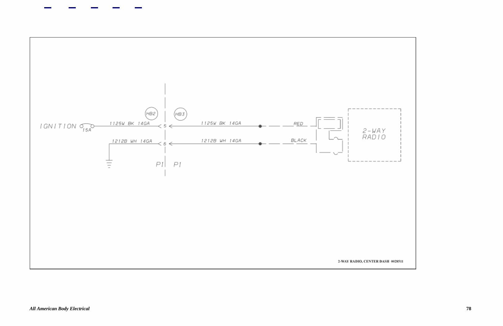
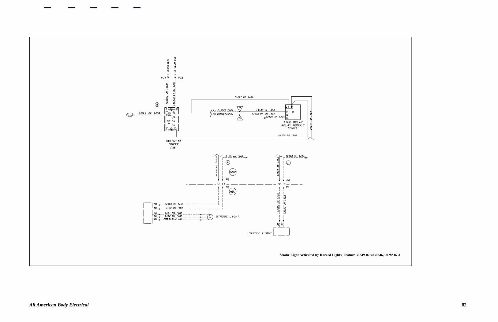
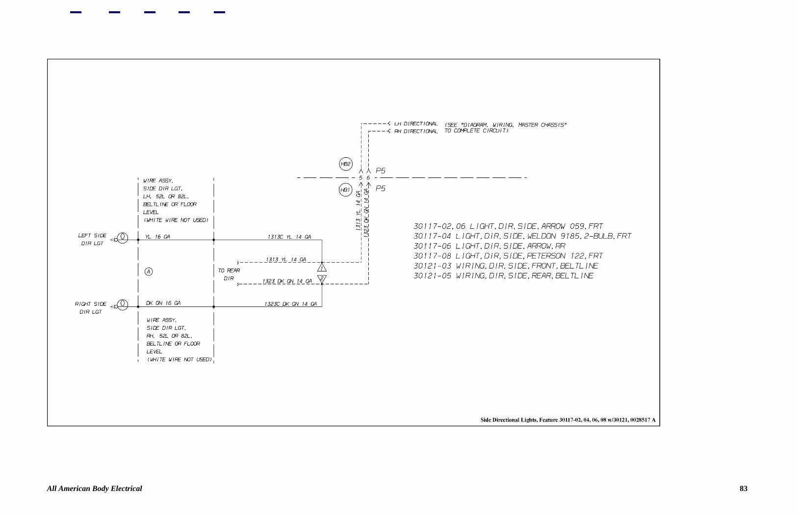
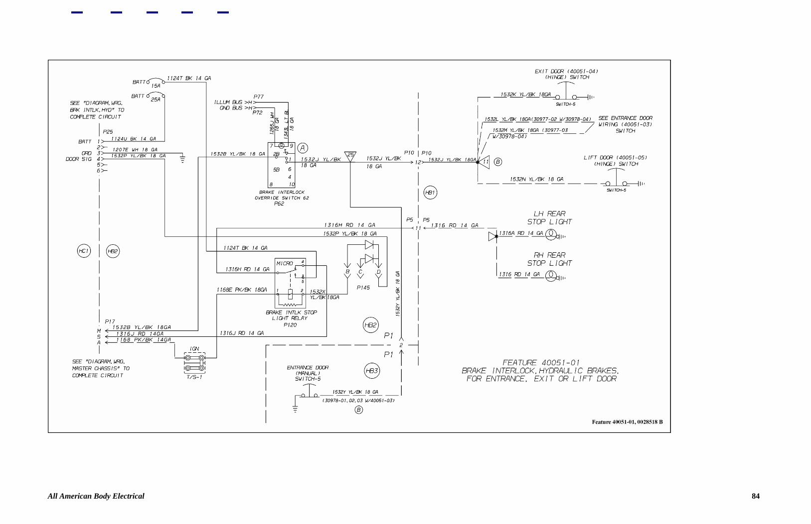
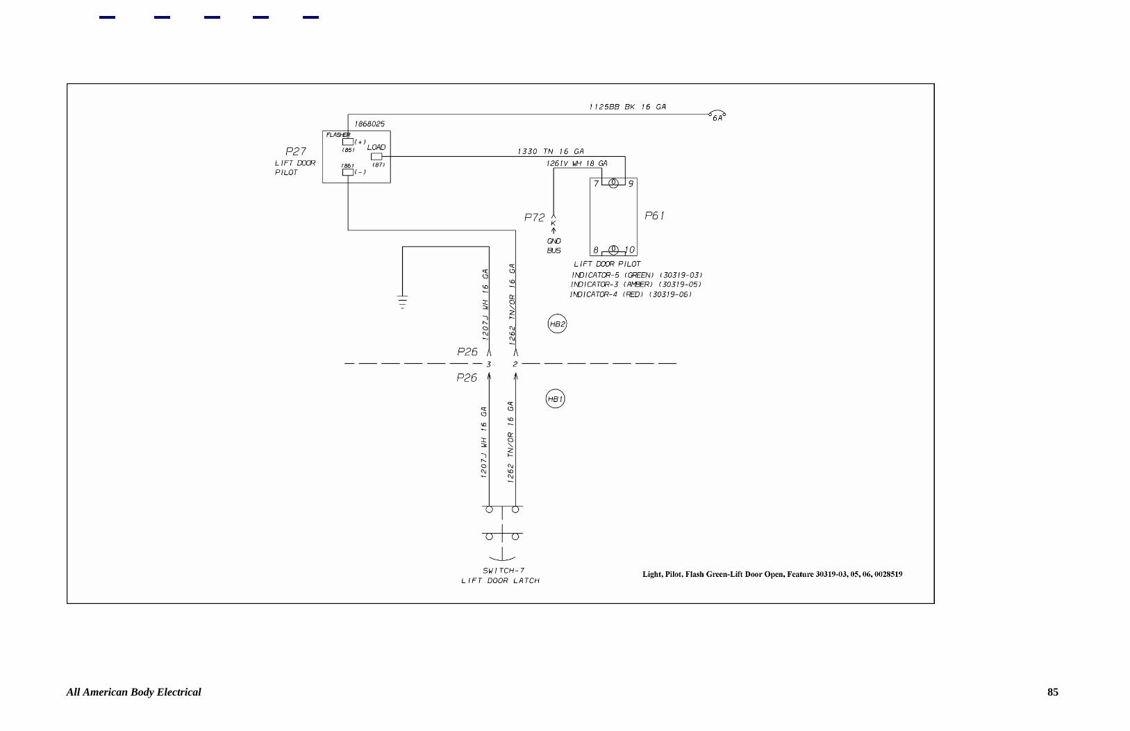
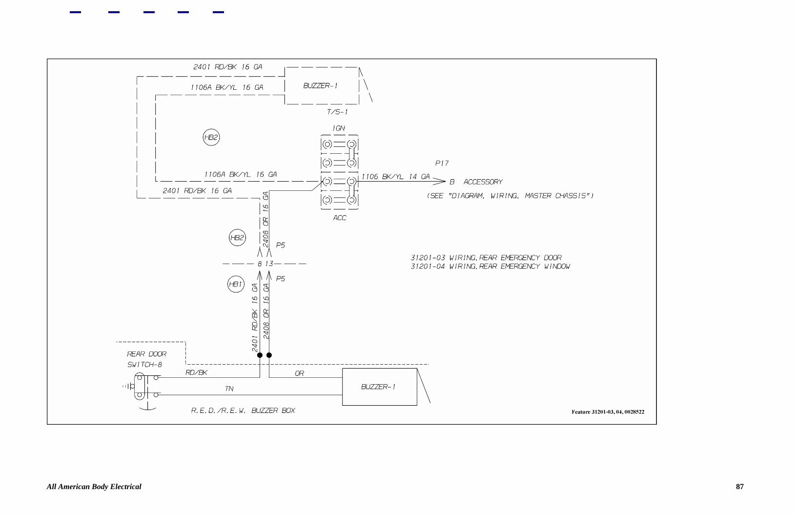
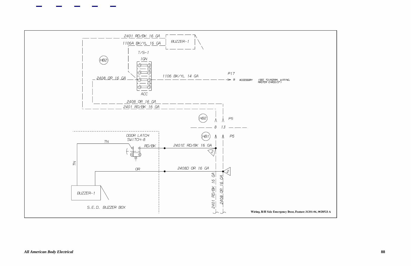
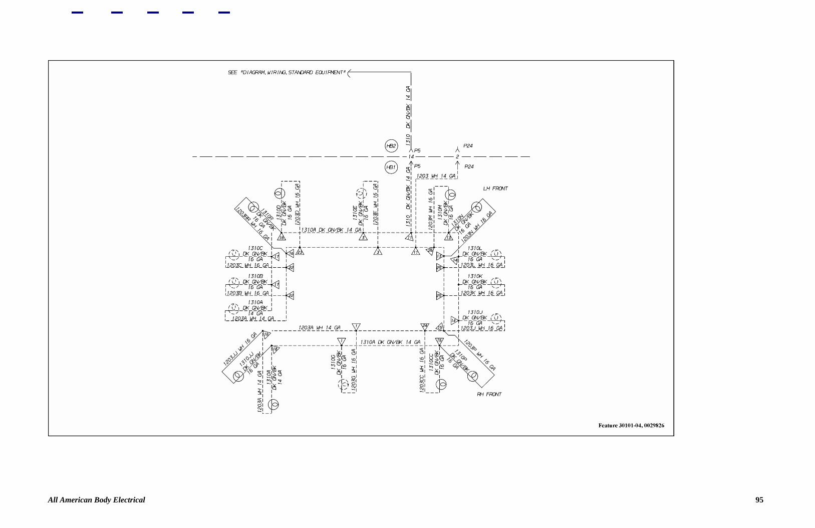
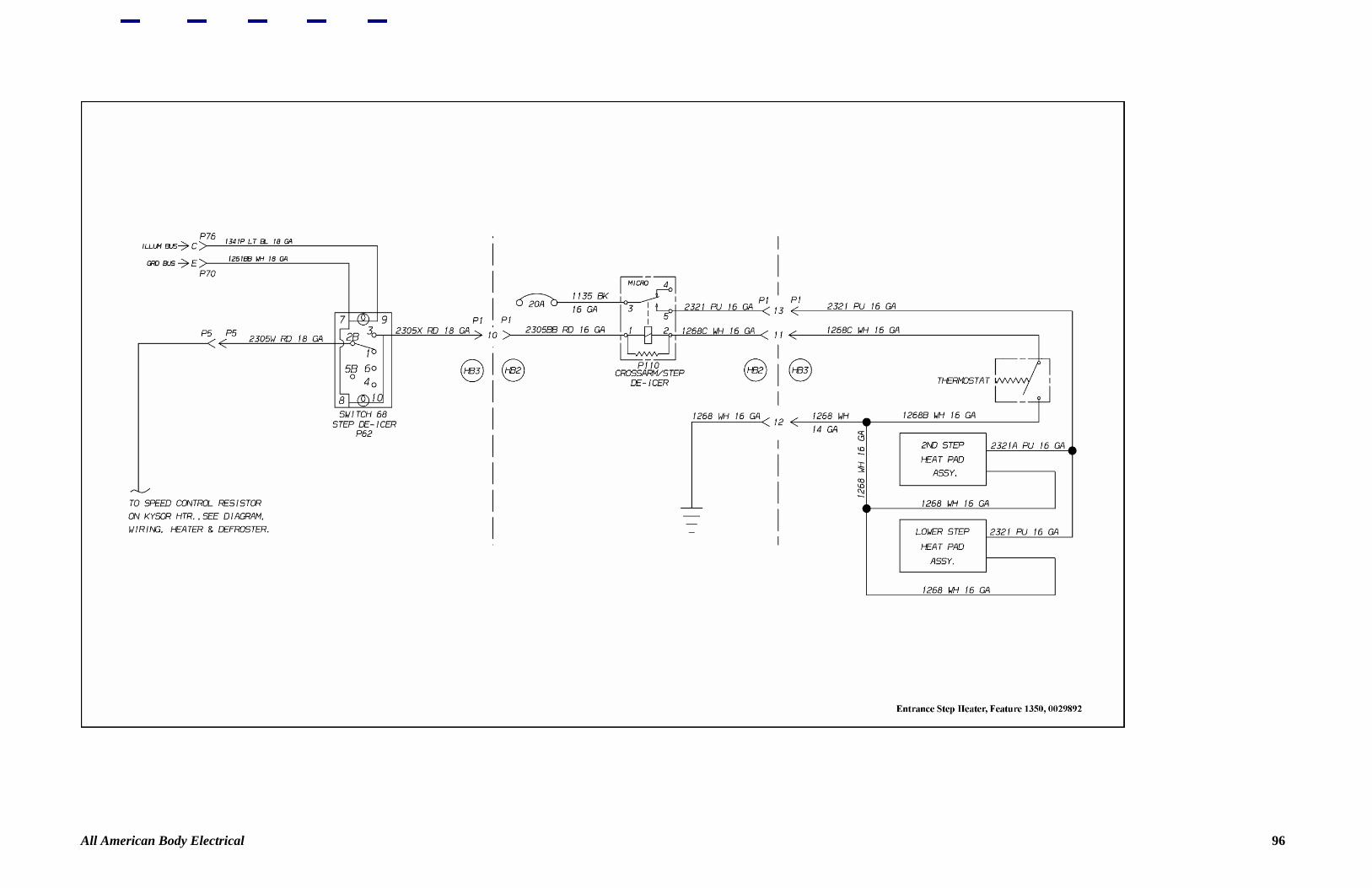
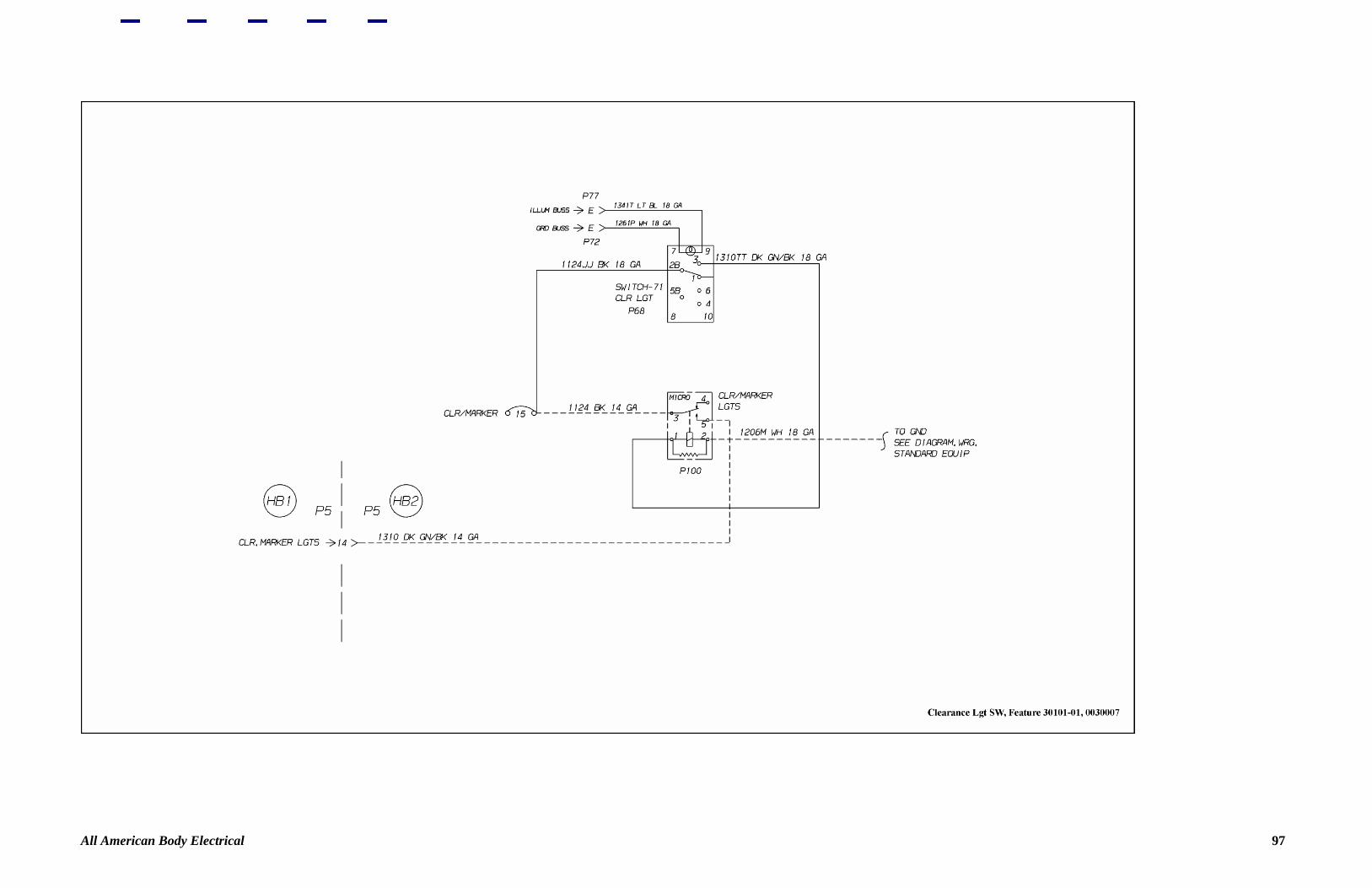
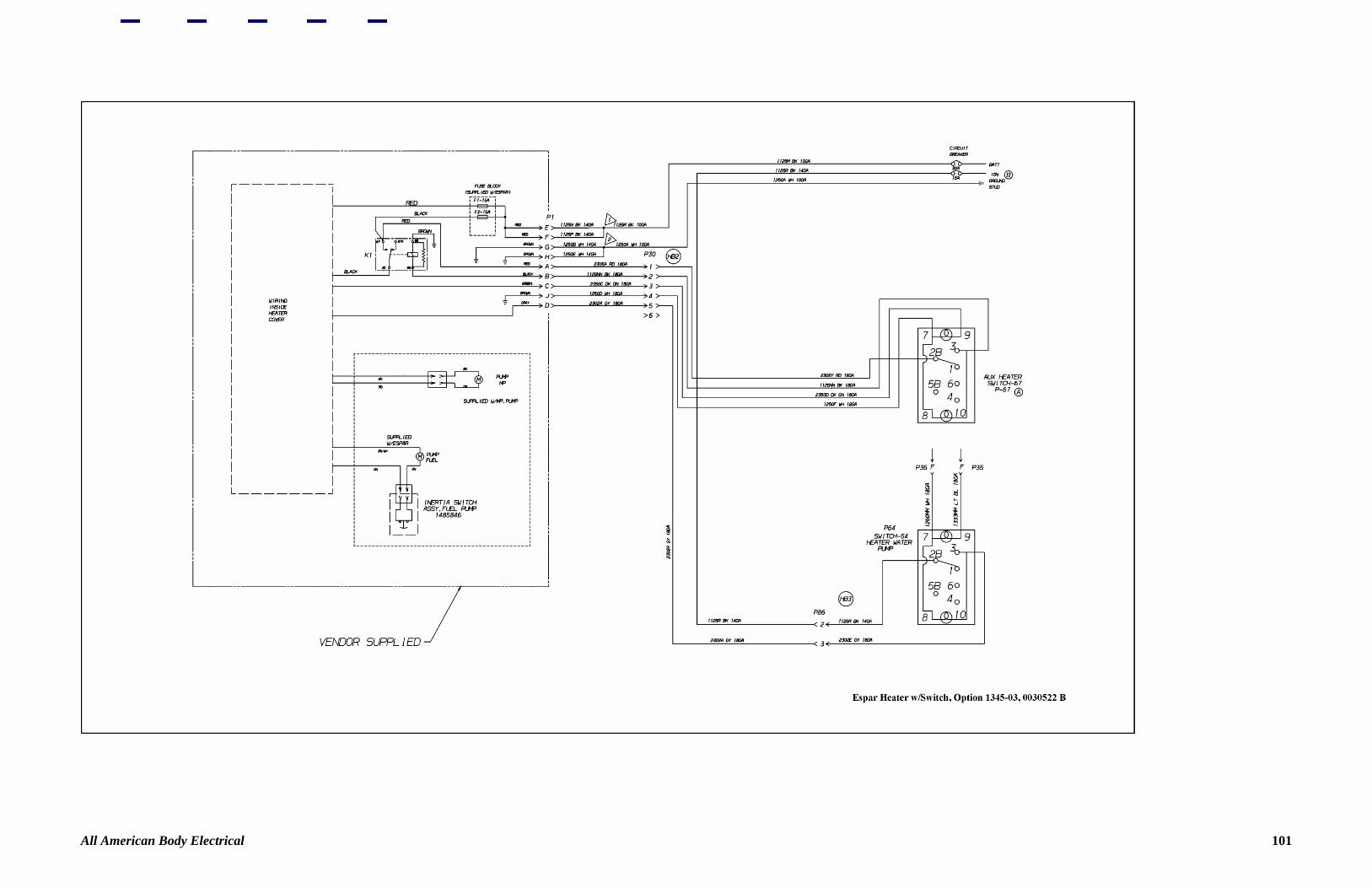
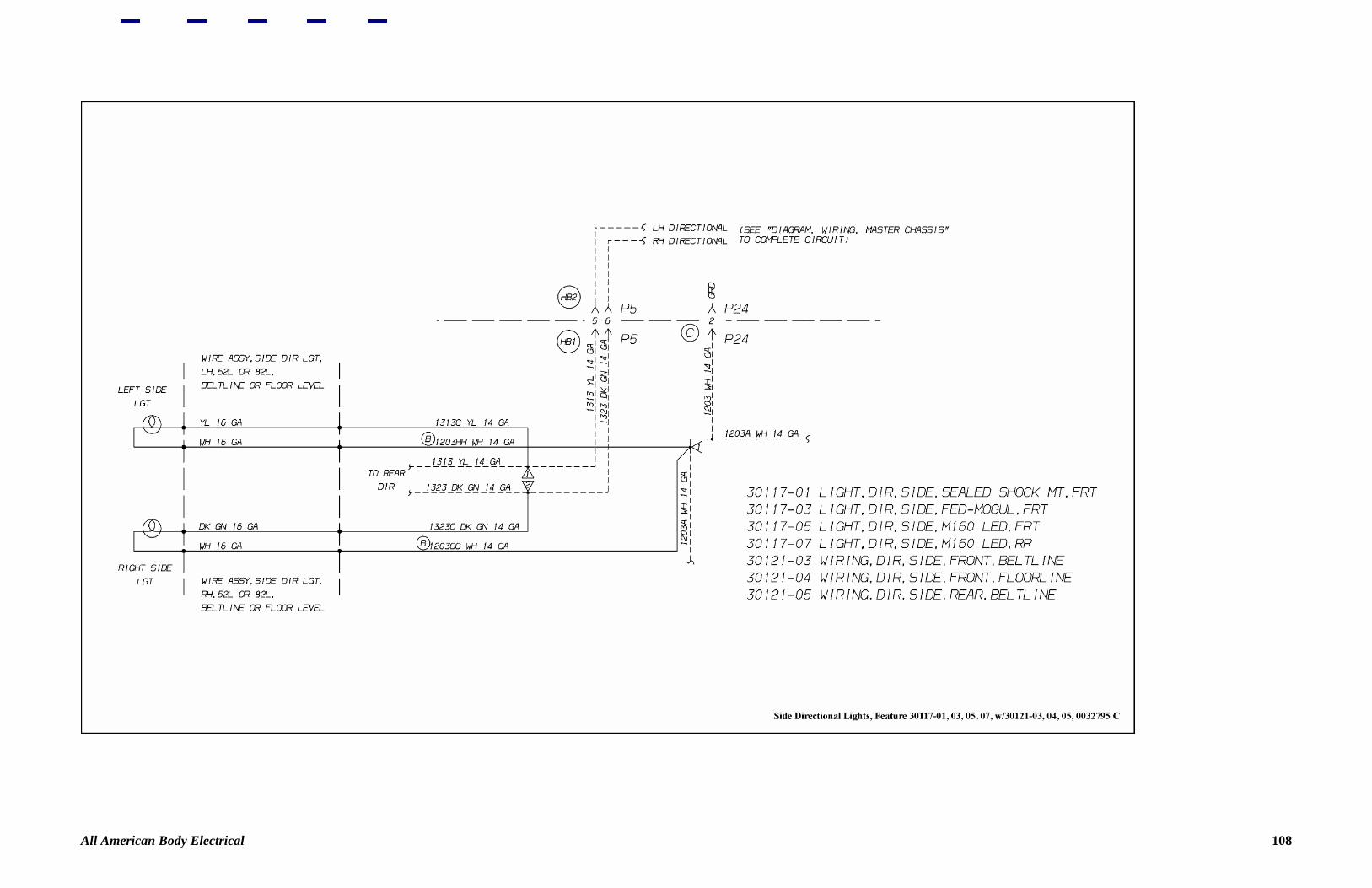
Figure 76—2-Way Radio, Center 78 Figure 77—Roof Mounted Strobe Light 79 Figure 78—Roof Mounted Strobe Light 80 Figure 79—Strobe Light Activated by Warning Light System 81 Figure 80—Strobe Light Activated by Hazard Light System 82 Figure 81—Side Directional Lights 83 Figure 82—Feature 40051-01 84 Figure 83—Light, Pilot, Flash Green 85 Figure 84—35" Exit Door 86 Figure 85—Feature 31201 87 Figure 86—Wiring, RH Side Emergency Door 88 Figure 87—LH Side Emergency Door 89 Figure 88—Back-up Lights Activated By RR Emergency Door 90 Figure 89—Back-up Lights Activated By RR Emergency Door 91 Figure 90—Vandal Lock for Rear Emergency Door 92 Figure 91—Vandal Lock for Left Side Emergency Door 93 Figure 92—Vandal Lock for Right Side Emergency Door 94 Figure 93—Feature 30101 95 Figure 94—Entrance Step Heater 96 Figure 95—Clearance Light 97 Figure 96—Foot Switch 98 Figure 97—Feature 30291 99 Figure 98—Option 1345-04 100 Figure 99—Espar Heater 101 Figure 100—Webasto with Switch 102 Figure 101—Feature 30193-01 103 Figure 102—Feature 30193-02 104 Figure 103—Pre-Wire for Video Monitor System 105 Figure 104—Armored Clearance Lights 106 Figure 105—Water Regulating Valve 107 Figure 106—Side Directional Lights 108
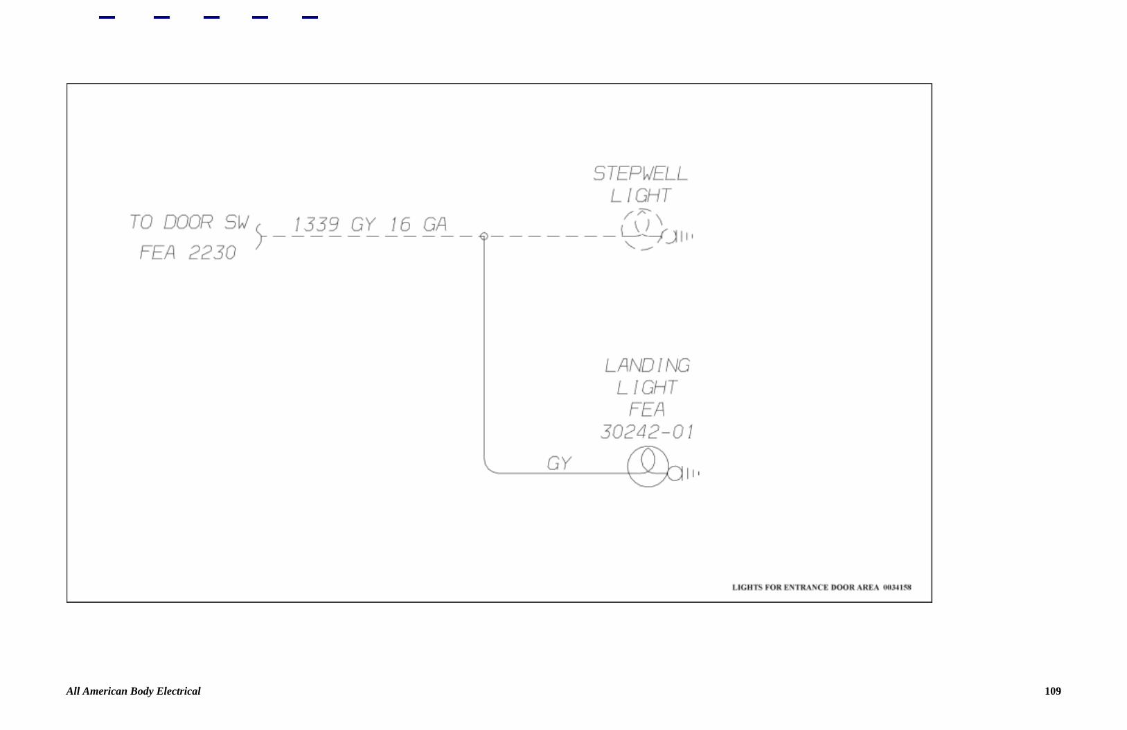
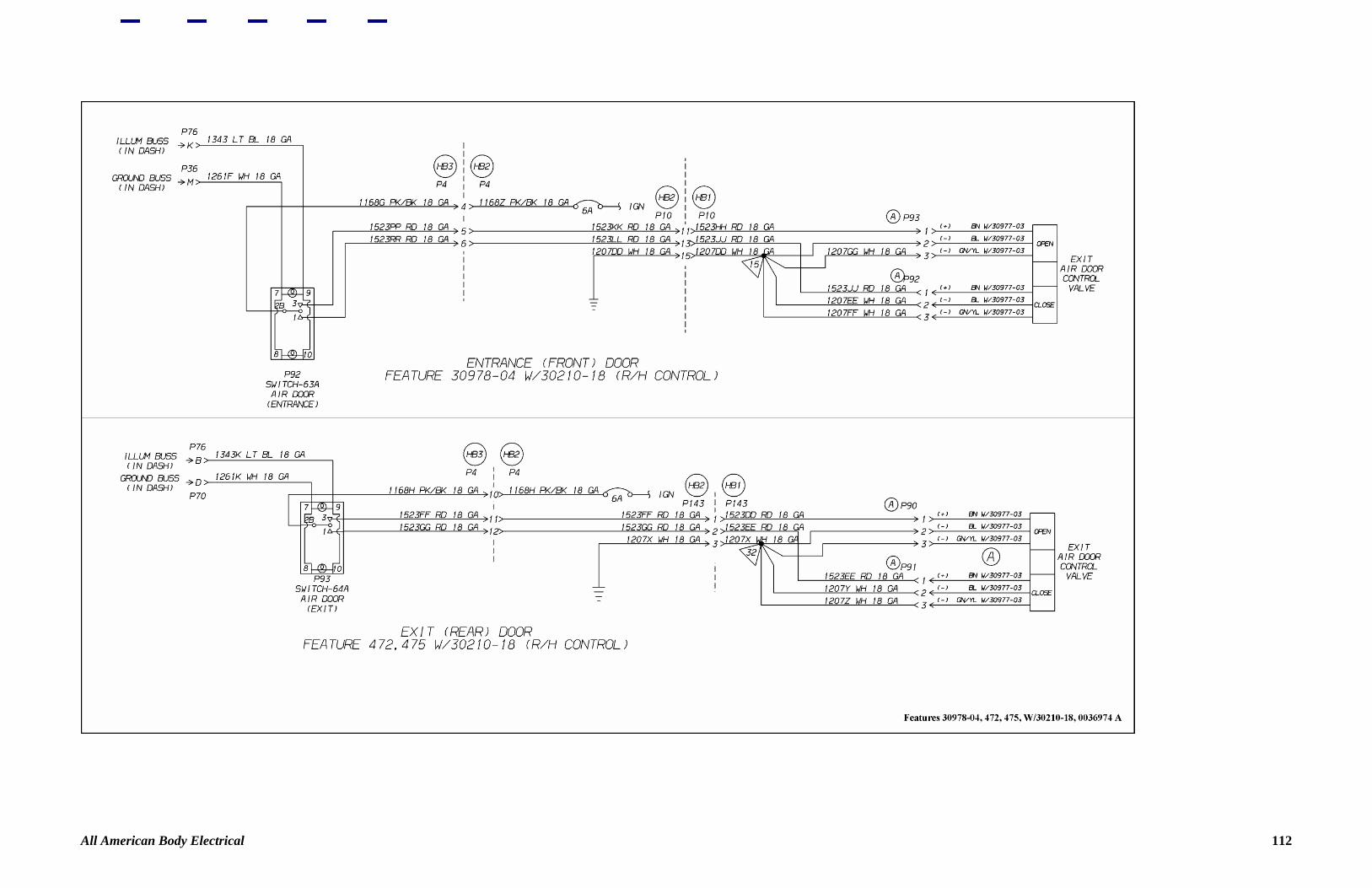
Figure 107—Lights for Entrance Door Area 109 Figure 108—Air Powered Door Control 110 Figure 109—Feature 30291 111 Figure 110—Feature 30978-04 112 Figure 111—Axle Assembly, RS-19-144 113
All American Body Electrical 2

All American Body Electrical 3
All American Body Electrical 4

All American Body Electrical 5
All American Body Electrical 6

All American Body Electrical 7

All American Body Electrical 8
All American Body Electrical 9
All American Body Electrical 10

All American Body Electrical 11

All American Body Electrical 12
All American Body Electrical 13
All American Body Electrical 14

All American Body Electrical 15

All American Body Electrical 16
All American Body Electrical 17
All American Body Electrical 18
All American Body Electrical 19

All American Body Electrical 20
All American Body Electrical 21

All American Body Electrical 22
All American Body Electrical 23
All American Body Electrical 24
All American Body Electrical 25
All American Body Electrical 26
All American Body Electrical 27
All American Body Electrical 28

All American Body Electrical 29
All American Body Electrical 30

All American Body Electrical 31
All American Body Electrical 32
All American Body Electrical 33
All American Body Electrical 34

All American Body Electrical 35
All American Body Electrical 36
All American Body Electrical 37

All American Body Electrical 38
All American Body Electrical 39
All American Body Electrical 40
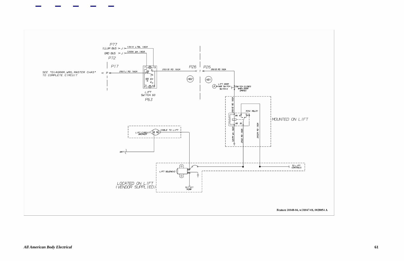
All American Body Electrical 41
All American Body Electrical 42

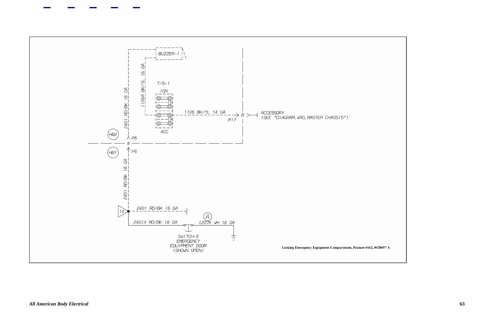
All American Body Electrical 43

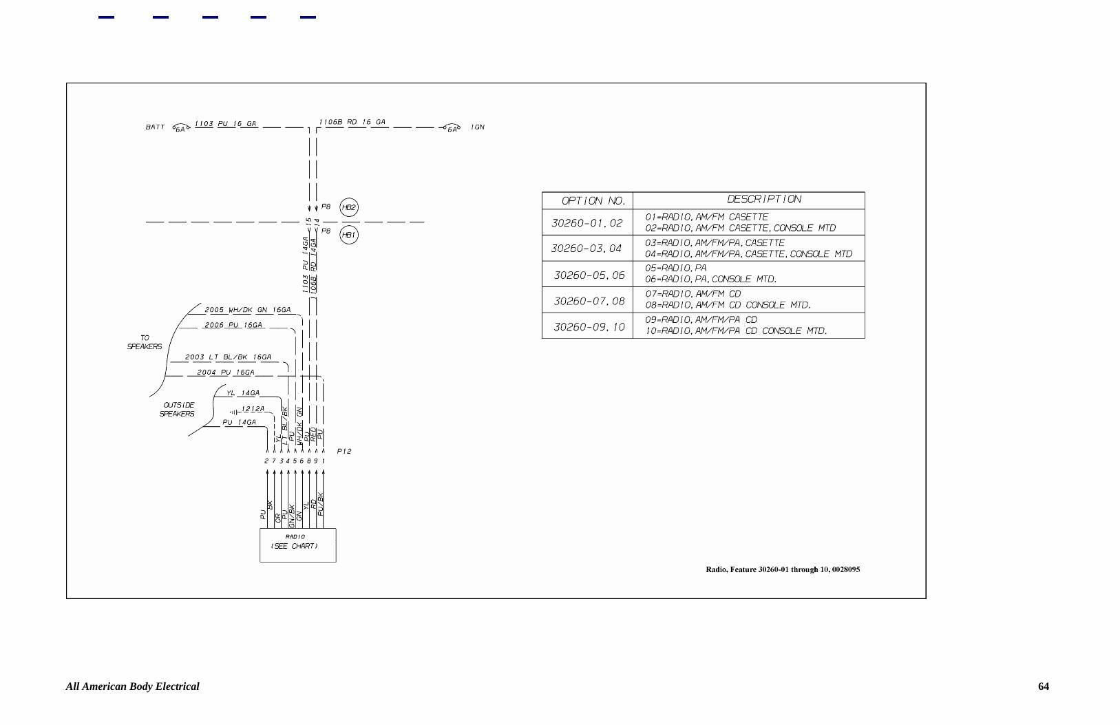
All American Body Electrical 44
All American Body Electrical 45
All American Body Electrical 46

All American Body Electrical 47
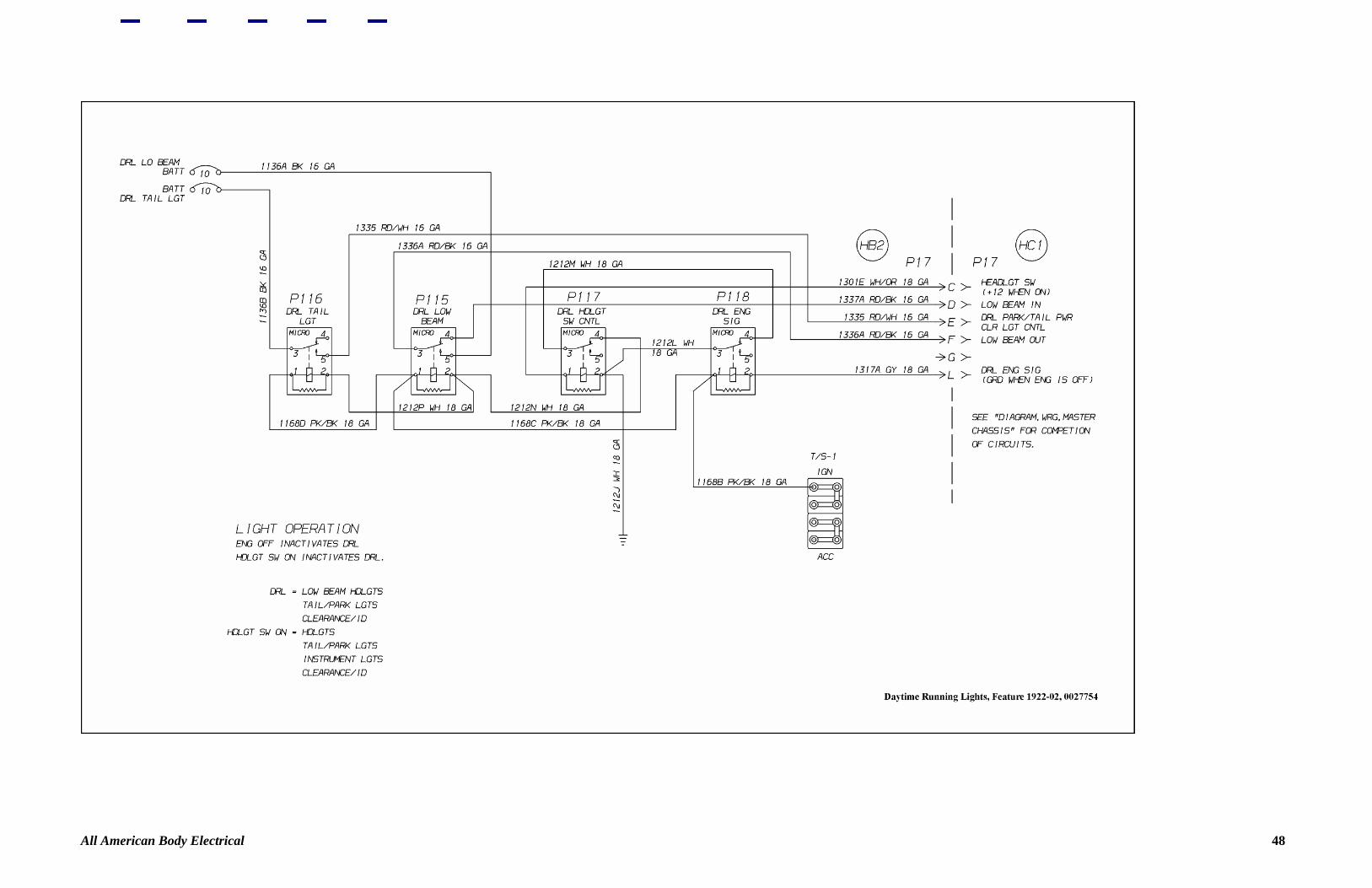
All American Body Electrical 48
All American Body Electrical 49

All American Body Electrical 50

All American Body Electrical 51
All American Body Electrical 52

All American Body Electrical 53
All American Body Electrical 54
All American Body Electrical 55
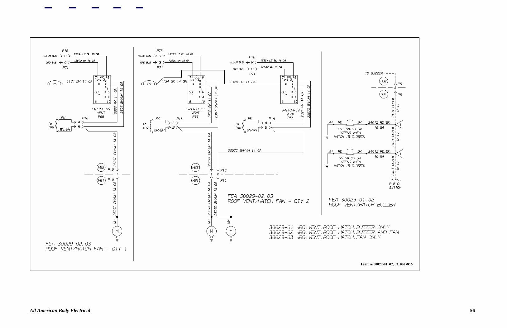
All American Body Electrical 56

All American Body Electrical 57
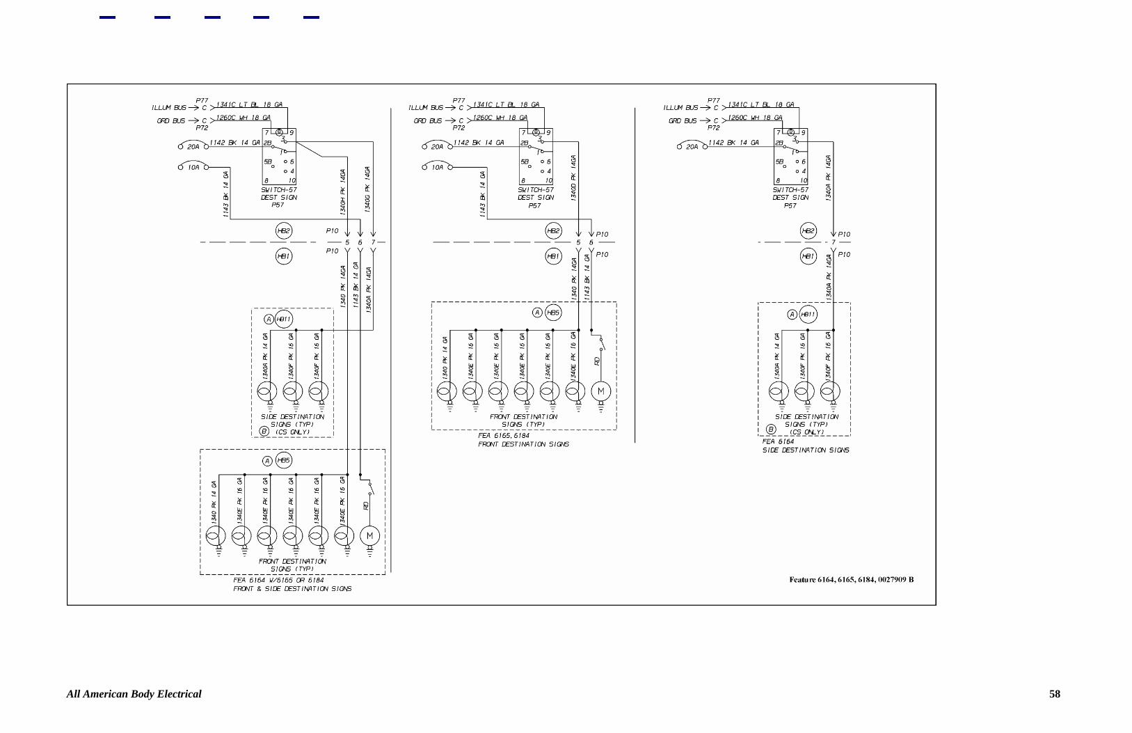
All American Body Electrical 58
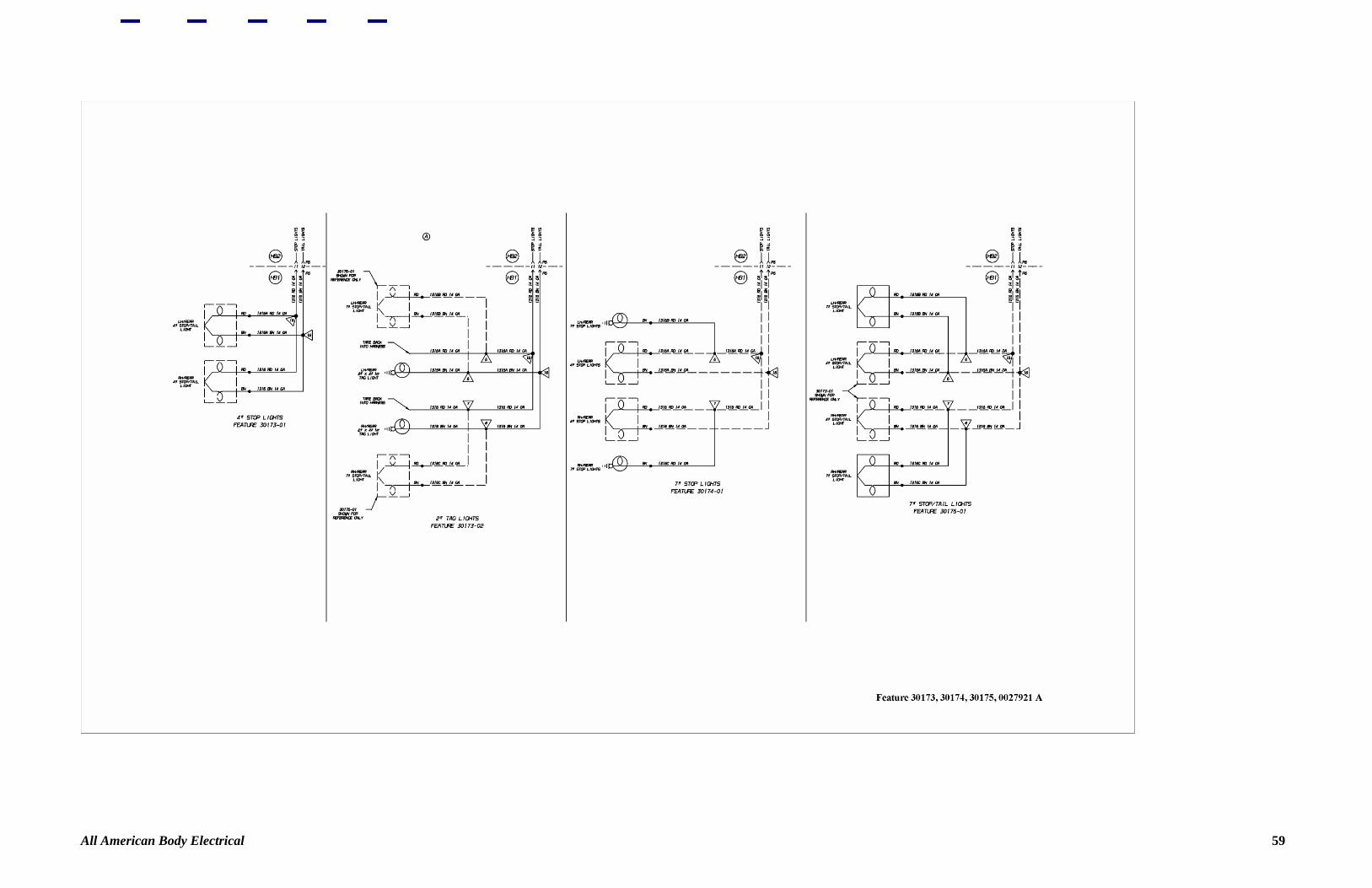
All American Body Electrical 59
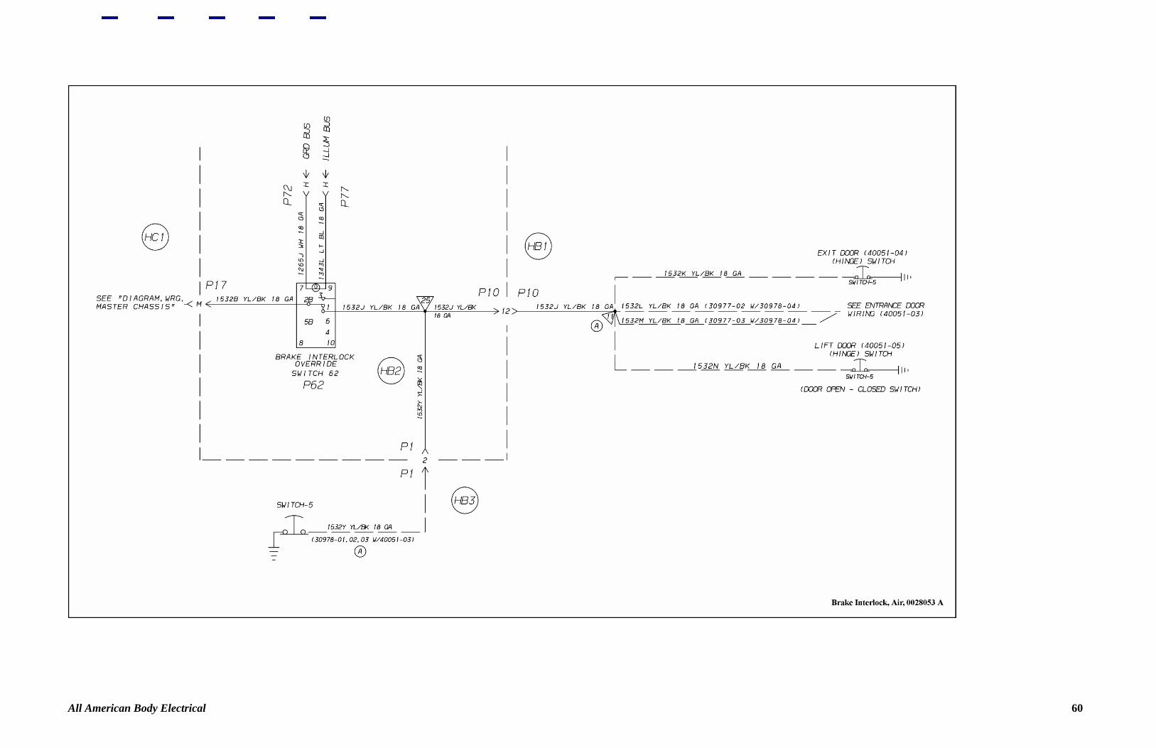
All American Body Electrical 60
All American Body Electrical 61

All American Body Electrical 62
All American Body Electrical 63
All American Body Electrical 64
All American Body Electrical 65
All American Body Electrical 66

All American Body Electrical 67

All American Body Electrical 68

All American Body Electrical 69

All American Body Electrical 70
All American Body Electrical 71
All American Body Electrical 72

All American Body Electrical 73
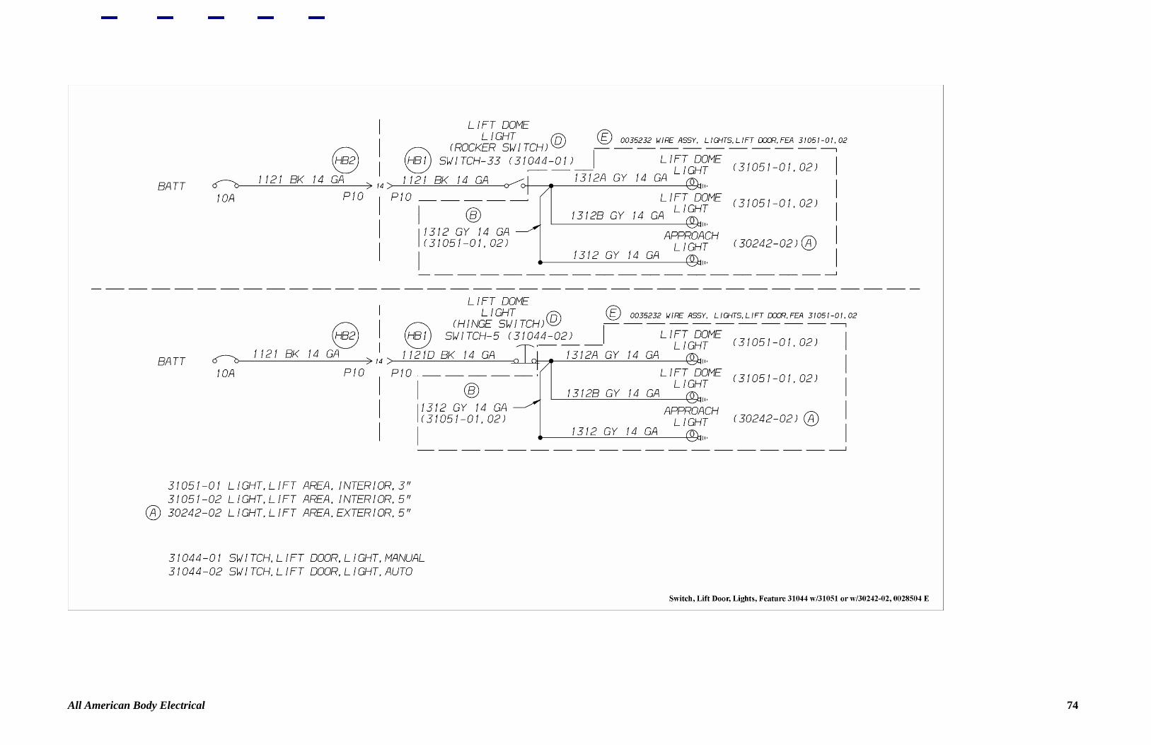
All American Body Electrical 74

All American Body Electrical 75

All American Body Electrical 76

All American Body Electrical 77
All American Body Electrical 78

All American Body Electrical 79

All American Body Electrical 80

All American Body Electrical 81
All American Body Electrical 82
All American Body Electrical 83
All American Body Electrical 84
All American Body Electrical 85

All American Body Electrical 86
All American Body Electrical 87
All American Body Electrical 88
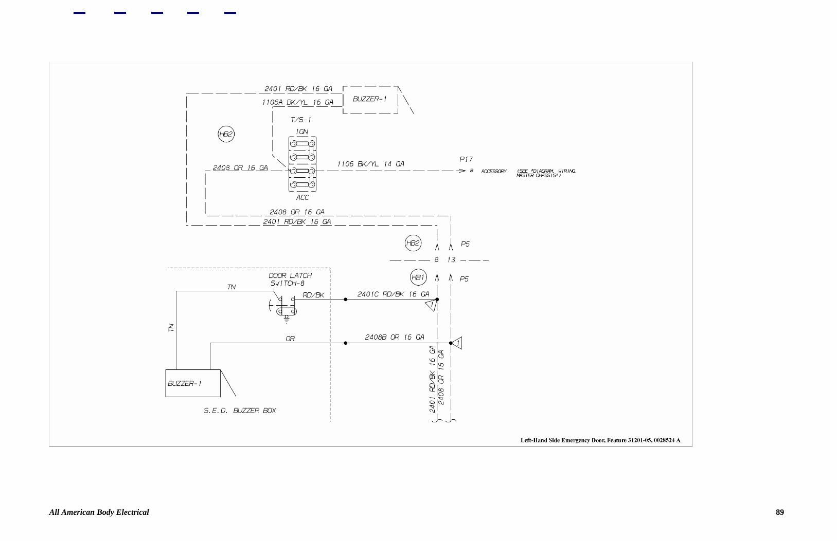
All American Body Electrical 89

All American Body Electrical 90
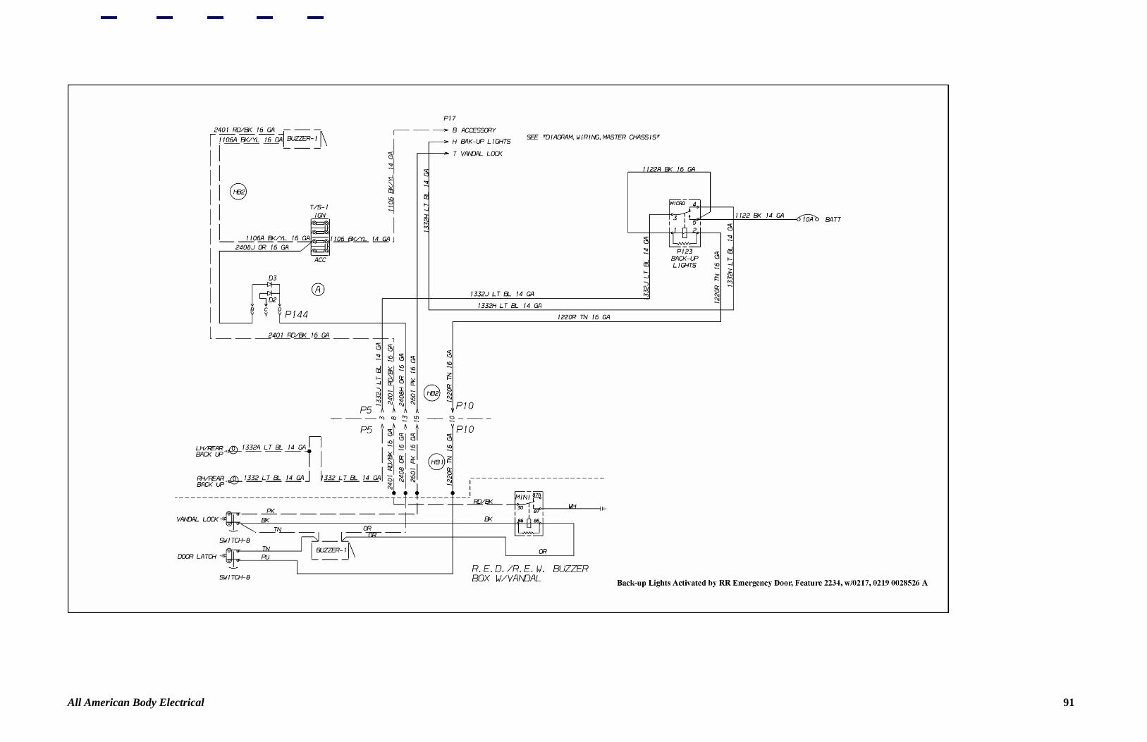
All American Body Electrical 91

All American Body Electrical 92
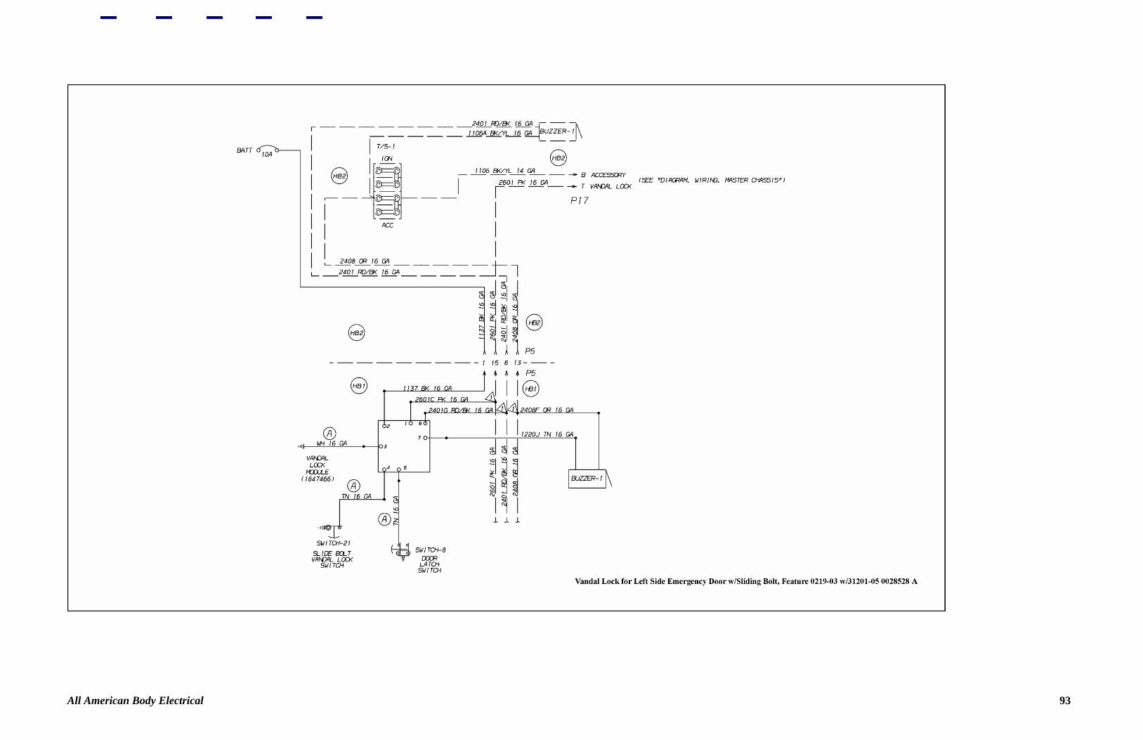
All American Body Electrical 93
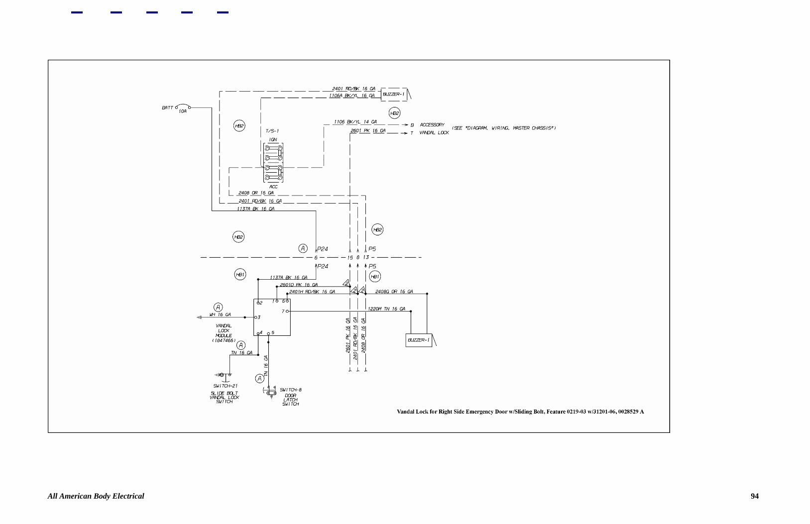
All American Body Electrical 94
All American Body Electrical 95
All American Body Electrical 96
All American Body Electrical 97

All American Body Electrical 98

All American Body Electrical 99

All American Body Electrical 100
All American Body Electrical 101

All American Body Electrical 102
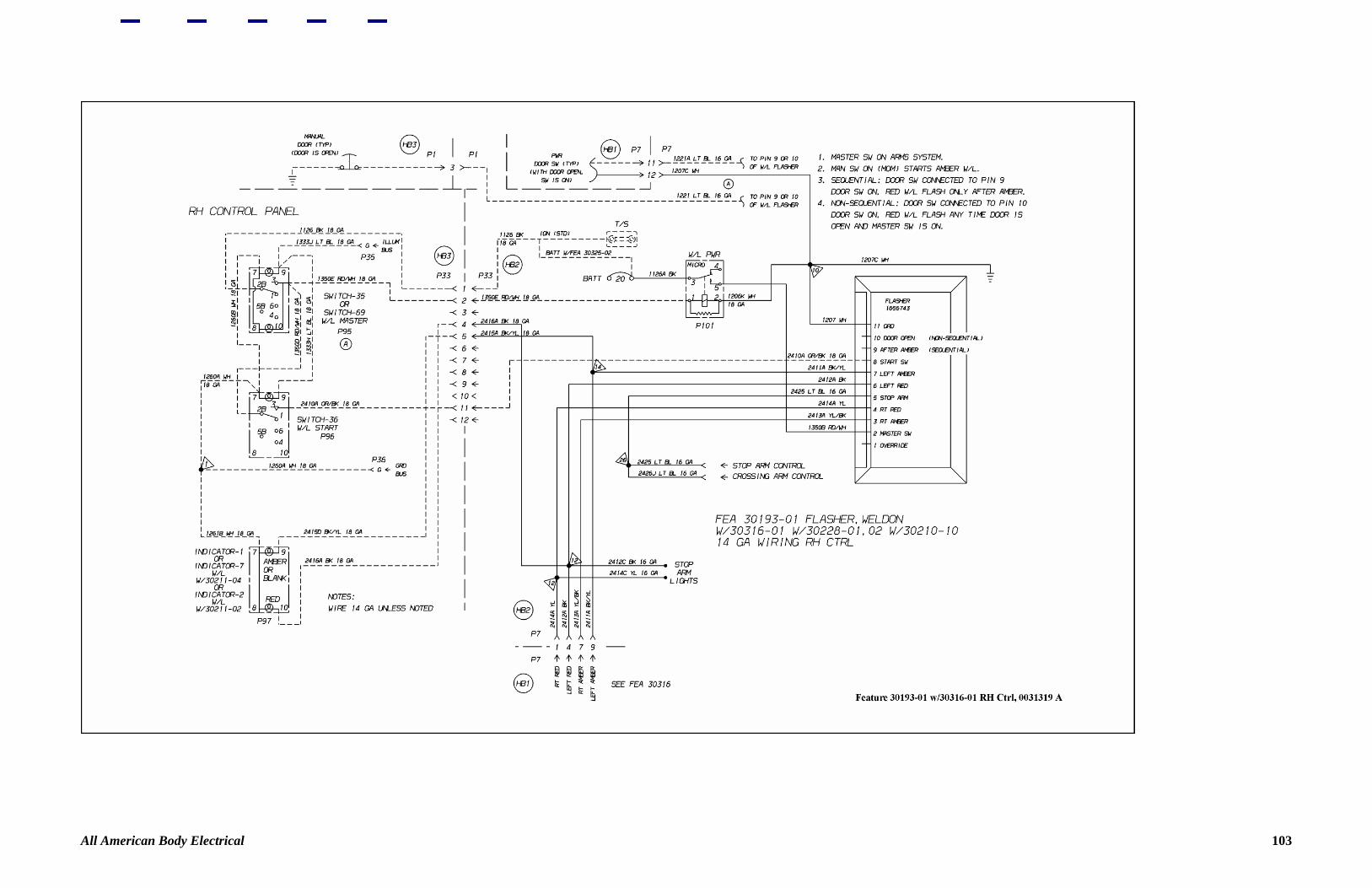
All American Body Electrical 103
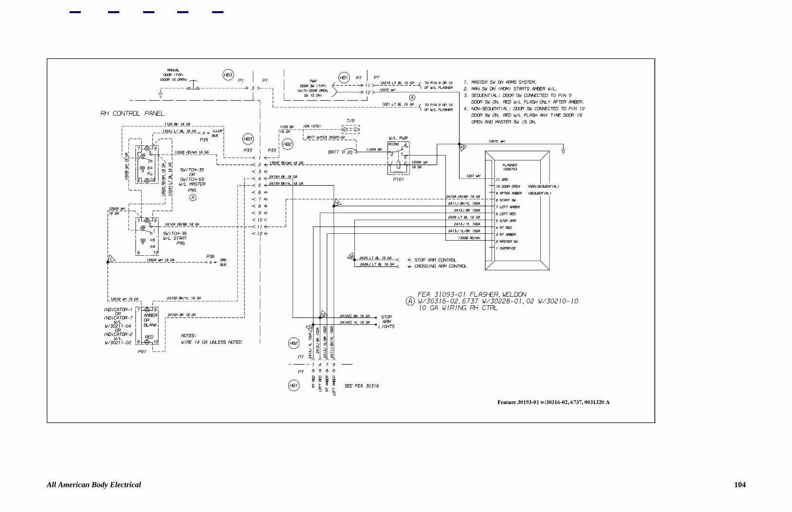
All American Body Electrical 104

All American Body Electrical 105
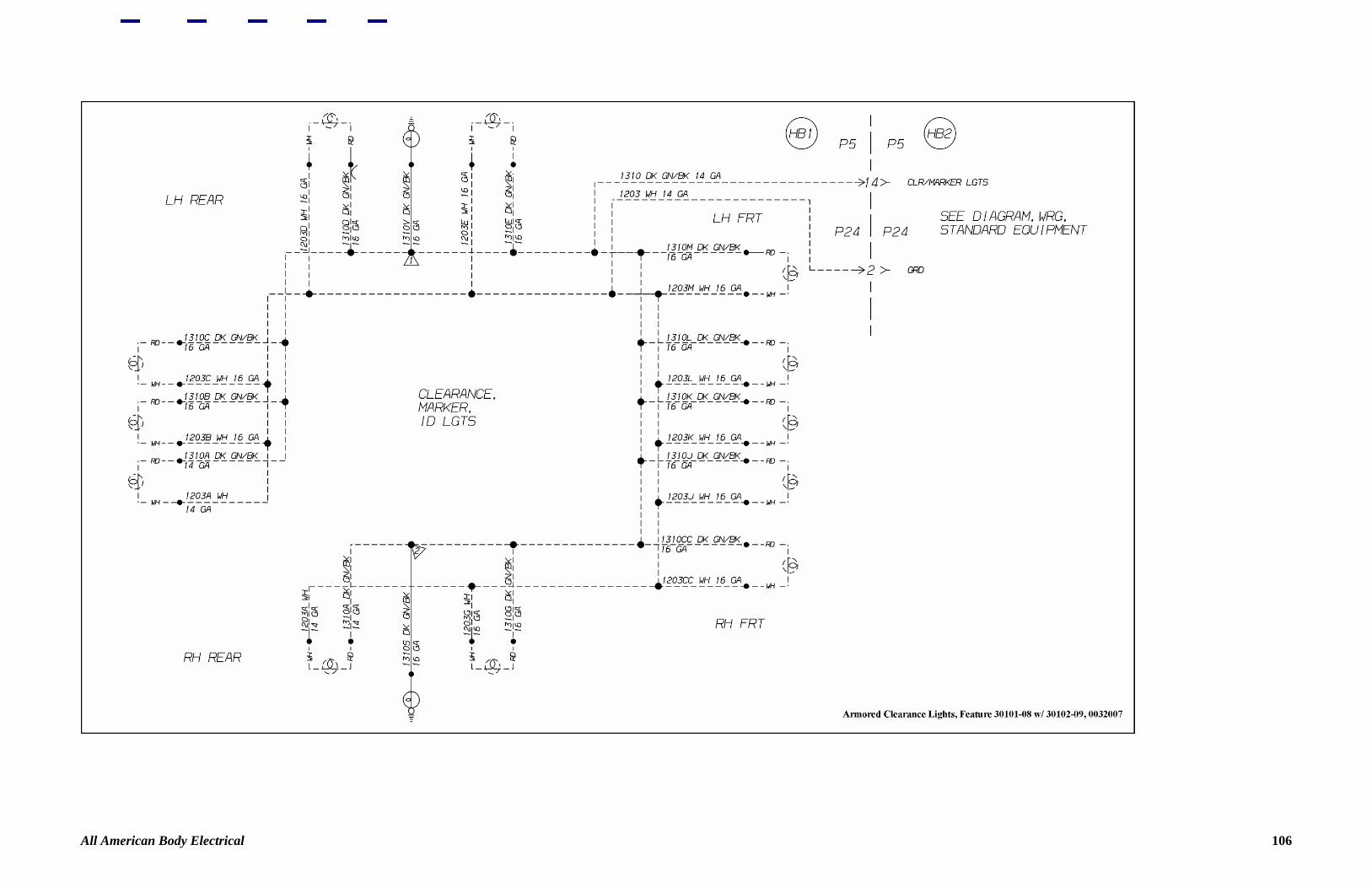
All American Body Electrical 106
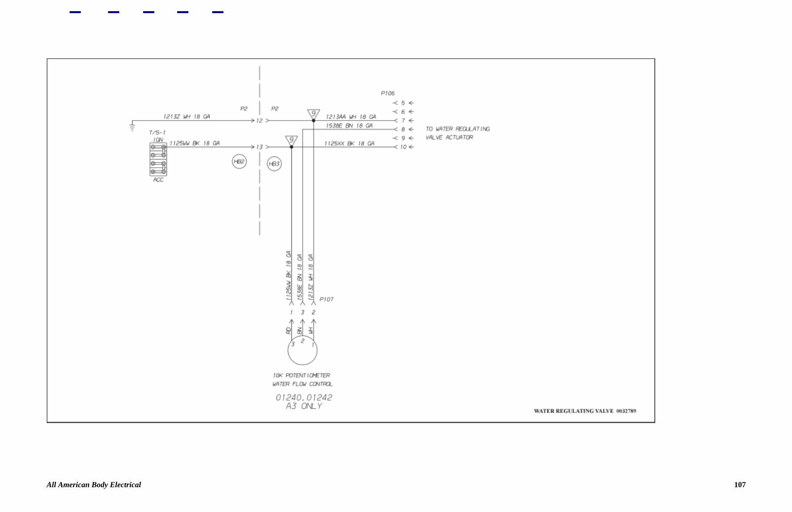
All American Body Electrical 107
All American Body Electrical 108
All American Body Electrical 109

All American Body Electrical 110

All American Body Electrical 111
All American Body Electrical 112

Back to Top
All American Body Electrical 113